WO2020255631A1 - プラズマエッチング方法 - Google Patents
プラズマエッチング方法 Download PDFInfo
- Publication number
- WO2020255631A1 WO2020255631A1 PCT/JP2020/020404 JP2020020404W WO2020255631A1 WO 2020255631 A1 WO2020255631 A1 WO 2020255631A1 JP 2020020404 W JP2020020404 W JP 2020020404W WO 2020255631 A1 WO2020255631 A1 WO 2020255631A1
- Authority
- WO
- WIPO (PCT)
- Prior art keywords
- etching
- plasma
- silicon nitride
- nitride film
- gas
- Prior art date
- Legal status (The legal status is an assumption and is not a legal conclusion. Google has not performed a legal analysis and makes no representation as to the accuracy of the status listed.)
- Ceased
Links
Images


Classifications
-
- H—ELECTRICITY
- H05—ELECTRIC TECHNIQUES NOT OTHERWISE PROVIDED FOR
- H05H—PLASMA TECHNIQUE; PRODUCTION OF ACCELERATED ELECTRICALLY-CHARGED PARTICLES OR OF NEUTRONS; PRODUCTION OR ACCELERATION OF NEUTRAL MOLECULAR OR ATOMIC BEAMS
- H05H1/00—Generating plasma; Handling plasma
- H05H1/24—Generating plasma
- H05H1/46—Generating plasma using applied electromagnetic fields, e.g. high frequency or microwave energy
-
- H—ELECTRICITY
- H01—ELECTRIC ELEMENTS
- H01J—ELECTRIC DISCHARGE TUBES OR DISCHARGE LAMPS
- H01J37/00—Discharge tubes with provision for introducing objects or material to be exposed to the discharge, e.g. for the purpose of examination or processing thereof
- H01J37/32—Gas-filled discharge tubes
- H01J37/32009—Arrangements for generation of plasma specially adapted for examination or treatment of objects, e.g. plasma sources
- H01J37/32082—Radio frequency generated discharge
-
- H—ELECTRICITY
- H10—SEMICONDUCTOR DEVICES; ELECTRIC SOLID-STATE DEVICES NOT OTHERWISE PROVIDED FOR
- H10P—GENERIC PROCESSES OR APPARATUS FOR THE MANUFACTURE OR TREATMENT OF DEVICES COVERED BY CLASS H10
- H10P50/00—Etching of wafers, substrates or parts of devices
- H10P50/20—Dry etching; Plasma etching; Reactive-ion etching
- H10P50/28—Dry etching; Plasma etching; Reactive-ion etching of insulating materials
- H10P50/282—Dry etching; Plasma etching; Reactive-ion etching of insulating materials of inorganic materials
- H10P50/283—Dry etching; Plasma etching; Reactive-ion etching of insulating materials of inorganic materials by chemical means
-
- H—ELECTRICITY
- H01—ELECTRIC ELEMENTS
- H01J—ELECTRIC DISCHARGE TUBES OR DISCHARGE LAMPS
- H01J37/00—Discharge tubes with provision for introducing objects or material to be exposed to the discharge, e.g. for the purpose of examination or processing thereof
- H01J37/32—Gas-filled discharge tubes
- H01J37/32009—Arrangements for generation of plasma specially adapted for examination or treatment of objects, e.g. plasma sources
- H01J37/32082—Radio frequency generated discharge
- H01J37/32174—Circuits specially adapted for controlling the RF discharge
-
- H—ELECTRICITY
- H01—ELECTRIC ELEMENTS
- H01J—ELECTRIC DISCHARGE TUBES OR DISCHARGE LAMPS
- H01J37/00—Discharge tubes with provision for introducing objects or material to be exposed to the discharge, e.g. for the purpose of examination or processing thereof
- H01J37/32—Gas-filled discharge tubes
- H01J37/32431—Constructional details of the reactor
- H01J37/32532—Electrodes
- H01J37/32568—Relative arrangement or disposition of electrodes; moving means
-
- H—ELECTRICITY
- H10—SEMICONDUCTOR DEVICES; ELECTRIC SOLID-STATE DEVICES NOT OTHERWISE PROVIDED FOR
- H10P—GENERIC PROCESSES OR APPARATUS FOR THE MANUFACTURE OR TREATMENT OF DEVICES COVERED BY CLASS H10
- H10P14/00—Formation of materials, e.g. in the shape of layers or pillars
- H10P14/60—Formation of materials, e.g. in the shape of layers or pillars of insulating materials
- H10P14/69—Inorganic materials
- H10P14/692—Inorganic materials composed of oxides, glassy oxides or oxide-based glasses
- H10P14/6921—Inorganic materials composed of oxides, glassy oxides or oxide-based glasses containing silicon
- H10P14/69215—Inorganic materials composed of oxides, glassy oxides or oxide-based glasses containing silicon the material being a silicon oxide, e.g. SiO2
-
- H—ELECTRICITY
- H10—SEMICONDUCTOR DEVICES; ELECTRIC SOLID-STATE DEVICES NOT OTHERWISE PROVIDED FOR
- H10P—GENERIC PROCESSES OR APPARATUS FOR THE MANUFACTURE OR TREATMENT OF DEVICES COVERED BY CLASS H10
- H10P14/00—Formation of materials, e.g. in the shape of layers or pillars
- H10P14/60—Formation of materials, e.g. in the shape of layers or pillars of insulating materials
- H10P14/69—Inorganic materials
- H10P14/694—Inorganic materials composed of nitrides
- H10P14/6943—Inorganic materials composed of nitrides containing silicon
- H10P14/69433—Inorganic materials composed of nitrides containing silicon the material being a silicon nitride not containing oxygen, e.g. SixNy or SixByNz
-
- H—ELECTRICITY
- H01—ELECTRIC ELEMENTS
- H01J—ELECTRIC DISCHARGE TUBES OR DISCHARGE LAMPS
- H01J2237/00—Discharge tubes exposing object to beam, e.g. for analysis treatment, etching, imaging
- H01J2237/32—Processing objects by plasma generation
- H01J2237/33—Processing objects by plasma generation characterised by the type of processing
- H01J2237/334—Etching
Definitions
- the present invention relates to a plasma etching method.
- the silicon nitride film may be etched by plasma etching using an etching gas.
- Patent Document 1 discloses a plasma etching method for etching a silicon nitride film by converting an etching gas containing a fluorinated gas such as sulfur hexafluoride (SF 6 ) into plasma.
- An object of the present invention is to provide a plasma etching method in which the etching rate of a silicon nitride film is high.
- a plasma etching method comprising an etching step of etching a silicon nitride film formed on a substrate by using plasma obtained by converting an etching gas containing iodine heptafluoride into plasma.
- a plasma etching method having a high etching rate of a silicon nitride film is provided.
- a silicon nitride film (for example, Si 3 N 4 film) formed on a substrate is used by using plasma obtained by converting an etching gas containing iodine hepta (IF 7 ) into plasma. ) Is provided with an etching process.
- plasma etching using an etching gas containing iodine heptafluoride, the silicon nitride film can be etched at a high etching rate.
- a silicon oxide film (for example, a SiO 2 film) can be etched together with the silicon nitride film. That is, if the substrate on which the silicon nitride film and the silicon oxide film are formed is etched by the plasma etching method of the present embodiment, the silicon nitride film and the silicon oxide film can be etched at the same time.
- the silicon nitride film can be etched at a higher etching rate than the silicon oxide film. That is, according to the plasma etching method of the present embodiment, the silicon nitride film can be selectively plasma-etched with respect to the silicon oxide film. For example, silicon nitride so that the ratio of the etching rate of the silicon nitride film to the etching rate of the silicon oxide film is 2 or more and 70 or less, and from the viewpoint of more stable control of etching, it is 3 or more and 30 or less. The film and the silicon oxide film can be etched.
- the silicon nitride film is selected during the etching process for forming shallow trench isolation (STI) using double patterning. Target removal can be performed efficiently. Further, if the etching selectivity of the silicon nitride film with respect to the silicon oxide film is improved (if the ratio of the etching rate of the silicon nitride film to the etching rate of the silicon oxide film is large), the plasma etching method is replaced with the wet etching method. It is also possible to do.
- STI shallow trench isolation
- Plasma etching by the plasma etching method of this embodiment can be performed using a plasma etching apparatus.
- the plasma source in the plasma etching apparatus is not particularly limited, but for example, high-frequency discharge plasma such as inductively coupled plasma (ICP: Inductively Coupled Plasma), capacitively coupled plasma (CCP: Capacitively Coupled Plasma), or electron cyclotron resonance plasma. (ECRP: Electron Cyclotron Resonance Plasma) and other microwave discharge plasmas can be mentioned.
- ICP Inductively coupled plasma
- CCP capacitively coupled plasma
- ECRP Electron Cyclotron Resonance Plasma
- the plasma etching apparatus of FIG. 1, which will be described in detail later, is a plasma etching apparatus using ICP as a plasma source.
- plasma etching is preferably performed under a process pressure of 0.2 Pa or more and 26.7 Pa or less, more preferably 1 Pa or more and 15 Pa or less, and 1 Pa or more and 10 Pa or less. It is more preferable to carry out the process under the process pressure of 3 Pa or more and 7 Pa or less.
- the higher the process pressure the more the dissociation of iodine heptafluoride is promoted, so that the selectivity for etching the silicon nitride film with respect to the silicon oxide film is improved. Further, the higher the process pressure, the higher the ignitability of the plasma.
- the etching gas may be formed only of iodine heptafluoride, but may be a mixed gas containing iodine heptafluoride and an inert gas.
- the type of the inert gas is not particularly limited, and examples thereof include helium, argon, neon, krypton, xenon, and nitrogen gas. One of these inert gases may be used alone, or two or more thereof may be used in combination.
- the mixing ratio of iodine heptafluoride and the inert gas may be adjusted in consideration of the ignitability of plasma and the like.
- the concentration of iodine heptafluoride in the etching gas can be more than 0% by volume and 100% by volume or less, and in order to make the ignitability of plasma more sufficient, it should be 5% by volume or more and 50% by volume or less. In order to sufficiently increase the etching selectivity of the silicon nitride film with respect to the silicon oxide film, it is more preferably 10% by volume or more and 30% by volume or less.
- the amount of etching gas used for example, the total flow rate of etching gas into the chamber where plasma etching is performed in the plasma etching apparatus may be adjusted according to the volume of the chamber, the exhaust capacity, the process pressure, and the like.
- a plasma etching apparatus for example, by applying a high frequency source power to an RF (radio frequency) coil to form an electric field and a magnetic field, the etching gas can be converted into plasma to generate plasma.
- the magnitude of the source power is not particularly limited, but it is preferably more than 0 W and 3000 W or less, more preferably 100 W or more and 1500 W or less, and further preferably 200 W or more and 1000 W or less.
- the magnitude of the source power may be set according to the desired etching rate.
- the etching rate of the silicon nitride film becomes sufficiently high, and the etching selectivity of the silicon nitride film with respect to the silicon oxide film becomes sufficiently high.
- the temperature of the substrate during plasma etching is not particularly limited, but is preferably ⁇ 20 ° C. or higher and 250 ° C. or lower, more preferably 0 ° C. or higher and 100 ° C. or lower, and 20 ° C. or higher and 70 ° C. or lower. It is more preferable to do so.
- the temperature of the substrate during plasma etching is within the above numerical range, deformation due to alteration, sublimation, etc. of the resist film formed on the substrate is suppressed, so that plasma etching can be performed with high patterning accuracy.
- Bias power may be applied to the lower electrode that supports the substrate during plasma etching. That is, the magnitude of the bias power applied to the lower electrode may be 0 W or may exceed 0 W.
- the bias power applied to the lower electrode is preferably 12000 W or less, more preferably 1500 W or less, and 300 W or less. Is even more preferable.
- the plasma etching apparatus of FIG. 1 is a plasma etching apparatus using ICP as a plasma source. First, the plasma etching apparatus of FIG. 1 will be described.
- the plasma etching apparatus of FIG. 1 includes a chamber 1 in which plasma etching is performed internally, a lower electrode 2 that supports a substrate 20 for plasma etching inside the chamber 1, and a bias power power supply that applies bias power to the lower electrode 2. (Not shown), an RF coil 15 that forms an electric field and a magnetic field for plasmalizing the etching gas inside the chamber 1, and a power source for source power that applies high-frequency source power to the RF coil 15 (not shown). ), A vacuum pump 13 that depressurizes the inside of the chamber 1, a pressure gauge 14 that measures the pressure inside the chamber 1, a sensor 16 that captures plasma emission generated by plasma generation, and a plasma emission captured by the sensor 16. A spectroscope 17 and a spectroscope 17 for monitoring the temporal change of plasma light emission are provided.
- a silicon nitride film and a silicon oxide film are formed on the surface of the substrate 20.
- the sensor 16 for example, a CCD (Charge-Coupled Device) image sensor can be used.
- a viewing window may be provided in the chamber 1 and the inside of the chamber 1 may be visually observed from the viewing window to confirm the temporal change of plasma emission.
- the chamber 1 is provided with an etching gas supply unit that supplies the etching gas inside the chamber 1.
- the etching gas supply unit includes a heptafluoride iodine gas supply unit 3 that supplies iodine heptafluoride gas, an inert gas supply unit 4 that supplies an inert gas, an iodine heptafluoride gas supply unit 3, and a chamber 1. It has an etching gas supply pipe 11 to be connected, and an inert gas supply pipe 12 to connect the inert gas supply unit 4 to an intermediate portion of the etching gas supply pipe 11.
- the iodine heptafluoride gas is supplied to the chamber 1 as the etching gas
- the iodine heptafluoride gas is sent from the iodine heptafluoride gas supply unit 3 to the etching gas supply pipe 11 to supply the etching gas.
- Iodine heptafluoride gas is supplied to the chamber 1 via the pipe 11.
- the iodine heptafluoride gas is sent from the iodine heptafluoride gas supply unit 3 to the etching gas supply pipe 11 and is not used.
- the inert gas from the active gas supply unit 4 to the etching gas supply pipe 11 via the inert gas supply pipe 12
- iodine heptafluoride gas and the inert gas are sent to the intermediate portion of the etching gas supply pipe 11. Is mixed to form a mixed gas, and this mixed gas is supplied to the chamber 1 via the etching gas supply pipe 11.
- the substrate 20 is placed on the lower electrode 2 arranged inside the chamber 1, and the pressure inside the chamber 1 is set to 1 Pa by the vacuum pump 13.
- the etching gas supply unit supplies the etching gas to the inside of the chamber 1.
- a high frequency (for example, 13.56 MHz) source power is applied to the RF coil 15, electrons are accelerated by forming an electric field and a magnetic field inside the chamber 1, and the accelerated electrons are the seven feet in the etching gas. It collides with the iodine molecule to generate new ions and electrons, resulting in an electric discharge and the formation of a plasma.
- the generation of plasma can be confirmed by using the sensor 16 and the spectroscope 17.
- the silicon nitride film and the silicon oxide film formed on the surface of the substrate 20 are etched.
- the amount of etching gas supplied to the chamber 1 and the concentration of iodine heptafluoride in the etching gas (mixed gas) are determined by the mass flow controllers installed in the etching gas supply pipe 11 and the inert gas supply pipe 12, respectively (FIG. (Not shown) can be adjusted by controlling the flow rates of iodine heptafluoride gas and inert gas, respectively.
- the process pressure is set to 1 Pa or more and 10 Pa or less, and the bias power is set to 1500 W or less.
- the ratio of the etching rate of the silicon nitride film to the etching rate of the silicon oxide film is 2 or more and 70 or less, or 3 or more and 30 or less from the viewpoint of more stable etching control.
- the silicon oxide film can be etched.
- Example 1 Plasma etching of the substrate was performed using an ICP etching apparatus RIE-200iP manufactured by SAMCO Co., Ltd., which has substantially the same configuration as the plasma etching apparatus of FIG.
- This substrate is a silicon nitride film (Si 3 N 4 film) and a silicon oxide film (SiO 2 film) formed on a silicon substrate by a chemical vapor deposition method.
- the volume inside the chamber is 46000 cm 3
- the etching gas is a mixed gas of iodine heptafluoride gas and argon.
- concentration of iodine heptafluoride in the etching gas was adjusted to 20% by volume by setting the flow rate of iodine heptafluoride gas to 10 sccm and the flow rate of argon to 40 sccm.
- sccm is a volumetric flow rate (cm 3 ) per minute standardized under the conditions of 0 ° C. and 1 atm.
- the process pressure inside the chamber is 1 Pa
- the source power is 500 W
- the bias power is 0 W
- the substrate temperature is 20 ° C
- the flow rate of iodine heptafluoride gas, the flow rate of argon, the process pressure, the source power, and the bias power was constantly monitored, and plasma etching was performed while confirming that there was no difference between the set value and the executed value. The results are shown in Table 1.
- Table 1 shows the time during which the silicon nitride film and the silicon oxide film are plasma-etched (etching time), the film thickness of the silicon nitride film and the silicon oxide film before and after etching, the silicon nitride film and the silicon oxide.
- etching time the time during which the silicon nitride film and the silicon oxide film are plasma-etched
- Table 1 shows the film thickness of the silicon nitride film and the silicon oxide film before and after etching, the silicon nitride film and the silicon oxide.
- the film thicknesses of the silicon nitride film and the silicon oxide film were measured using a reflectance spectroscopic film thickness meter F20 manufactured by Filmometrics.
- the etching rate of the silicon nitride film and the silicon oxide film was calculated by subtracting the film thickness after etching from the film thickness before etching and dividing it by the etching time.
- Example 2 Plasma etching was performed in the same manner as in Example 1 except that the process pressure was changed as shown in Table 1, and the etching rates of the silicon nitride film and the silicon oxide film, and the silicon nitride film with respect to the etching rate of the silicon oxide film. The ratio of the etching rates of The results are shown in Table 1.
- etching gas was a mixed gas of sulfur hexafluoride gas and argon (the concentration of sulfur hexafluoride in the etching gas is 20% by volume) and that the process pressure was changed as shown in Table 1.
- Plasma etching was performed in the same manner as in Example 1, and the etching rates of the silicon nitride film and the silicon oxide film and the ratio of the etching rate of the silicon nitride film to the etching rate of the silicon oxide film were calculated. The results are shown in Table 1.
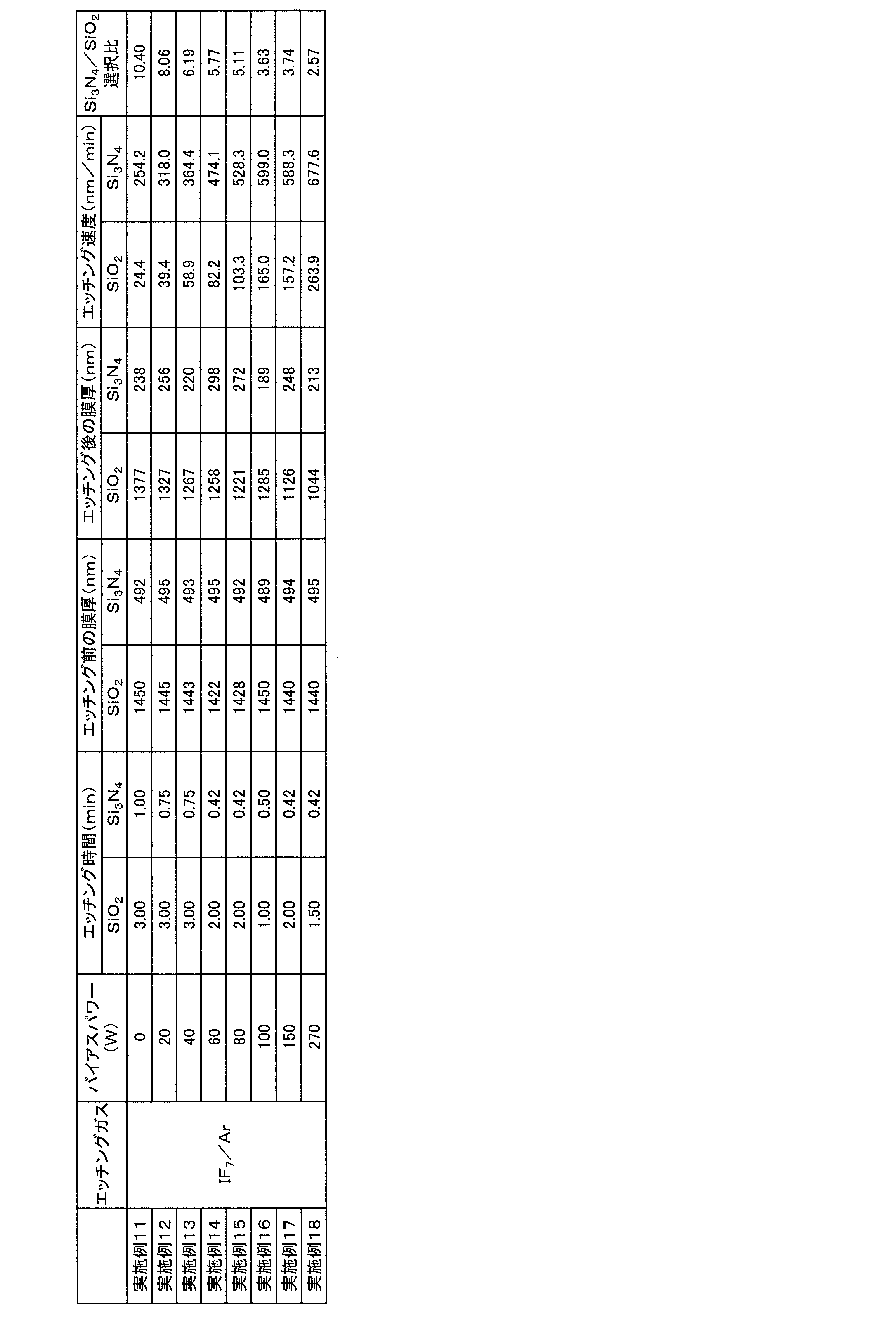
- Example 11 to 18 Plasma etching was performed in the same manner as in Example 1 except that the process pressure was set to 3 Pa and the bias power was changed as shown in Table 2, and the etching rates of the silicon nitride film and the silicon oxide film, and oxidation. The ratio of the etching rate of the silicon nitride film to the etching rate of the silicon film was calculated. The results are shown in Table 2.
- Example 21 to 24 Plasma etching was performed in the same manner as in Example 1 except that the process pressure was set to 5 Pa and the bias power was changed as shown in Table 3, and the etching rates of the silicon nitride film and the silicon oxide film, and oxidation The ratio of the etching rate of the silicon nitride film to the etching rate of the silicon film was calculated. The results are shown in Table 3.
- Table 3 shows the etching gas as a mixed gas of sulfur hexafluoride gas and argon (the concentration of sulfur hexafluoride in the etching gas is 20% by volume), the process pressure as 5 Pa, and the bias power.
- Plasma etching was performed in the same manner as in Example 1 except for the changes shown in the above, and the etching rates of the silicon nitride film and the silicon oxide film, and the ratio of the etching rate of the silicon nitride film to the etching rate of the silicon oxide film. was calculated. The results are shown in Table 3.
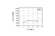
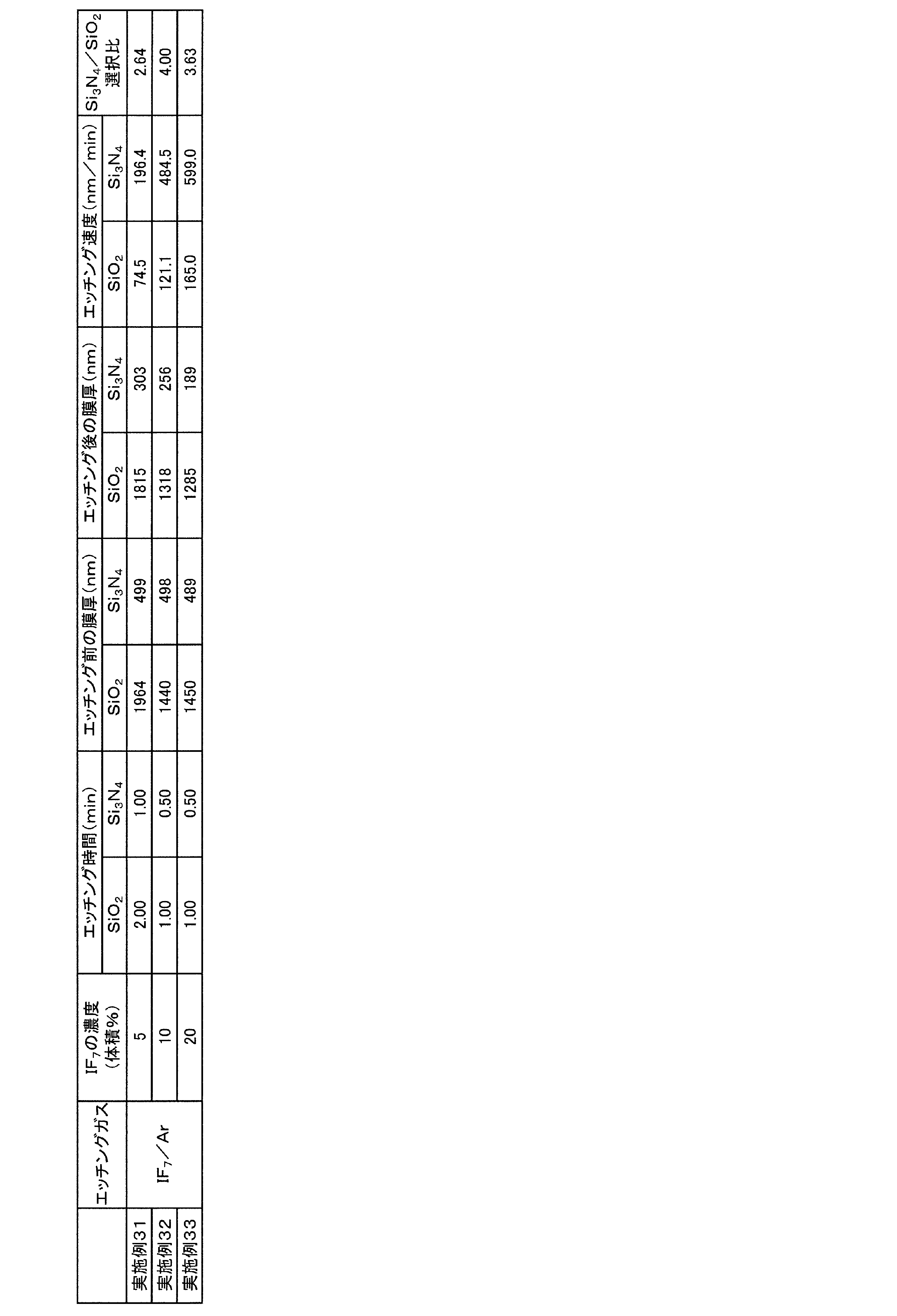
- Examples 31 to 33 Plasma etching was performed in the same manner as in Example 1 except that the process pressure was set to 3 Pa and the concentration of iodine heptafluoride in the etching gas was changed as shown in Table 4, and the silicon nitride film and the silicon oxide film were subjected to plasma etching. The ratio of the etching rate of the silicon nitride film to the etching rate of the silicon oxide film was calculated. The results are shown in Table 4.
- the concentration of iodine heptafluoride in the etching gas was adjusted by adjusting the flow rates of iodine heptafluoride gas and argon as follows. That is, by setting the flow rate of iodine heptafluoride gas to 2.5 sccm and the flow rate of argon to 47.5 sccm, the concentration of iodine heptafluoride in the etching gas is adjusted to 5% by volume, and the flow rate of iodine heptafluoride gas is adjusted to 5% by volume.
- the concentration of iodine heptafluoride in the etching gas is adjusted to 10% by volume, the flow rate of iodine heptafluoride gas is set to 10 sccm, and the flow rate of argon is set to 40 sccm.
- the concentration of iodine heptafluoride in the etching gas was adjusted to 20% by volume.
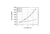
- Tables 1 to 4 are shown in the graphs of FIGS. 2 to 5, respectively. From the graphs of Table 1 and FIG. 2, at any process pressure, the etching gas containing iodine heptafluoride has more silicon nitride with respect to the etching rate of the silicon oxide film than the etching gas containing sulfur hexafluoride. It can be seen that the ratio of the etching rates of the films (Si 3 N 4 / SiO 2 selectivity) is large, and the silicon nitride film is selectively etched with respect to the silicon oxide film. It can be seen that the Si 3 N 4 / SiO 2 selectivity increases as the process pressure increases.
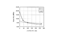
- the etching gas containing iodine heptafluoride has a higher ratio to the etching rate of the silicon oxide film than the etching gas containing sulfur hexafluoride. It can be seen that the ratio of the etching rates of the silicon nitride film is large, and the silicon nitride film is selectively etched with respect to the silicon oxide film. It can be seen that the Si 3 N 4 / SiO 2 selection ratio improves as the bias power decreases.
Landscapes
- Physics & Mathematics (AREA)
- Engineering & Computer Science (AREA)
- Plasma & Fusion (AREA)
- Chemical & Material Sciences (AREA)
- Analytical Chemistry (AREA)
- Electromagnetism (AREA)
- Spectroscopy & Molecular Physics (AREA)
- Drying Of Semiconductors (AREA)
Abstract
Description
本発明は、窒化シリコン膜のエッチング速度が大きいプラズマエッチング方法を提供することを課題とする。
[1] 七フッ化ヨウ素を含有するエッチングガスをプラズマ化して得られたプラズマを用いて、基板上に形成された窒化シリコン膜をエッチングするエッチング工程を備えるプラズマエッチング方法。
[3] 前記窒化シリコン膜のエッチング速度が前記酸化シリコン膜のエッチング速度よりも大きい[2]に記載のプラズマエッチング方法。
[5] 前記エッチングガスが七フッ化ヨウ素と不活性ガスとを含有する混合ガスである[1]~[4]のいずれか一項に記載のプラズマエッチング方法。
[7] 前記基板を支持する下部電極に0W以上1500W以下のバイアスパワーを印加しつつエッチングを行う[1]~[6]のいずれか一項に記載のプラズマエッチング方法。
エッチングガスの使用量、例えば、プラズマエッチング装置においてプラズマエッチングが行われるチャンバーへのエッチングガスの総流量は、チャンバーの体積、排気能力、及びプロセス圧力等に応じて調整するとよい。
エッチングガスのチャンバー1への供給量や、エッチングガス(混合ガス)中の七フッ化ヨウ素の濃度は、エッチングガス供給用配管11及び不活性ガス供給用配管12にそれぞれ設置されたマスフローコントローラー(図示せず)で七フッ化ヨウ素ガス及び不活性ガスの流量をそれぞれ制御することによって調整することができる。
(実施例1)
図1のプラズマエッチング装置と略同様の構成を有するサムコ株式会社製のICPエッチング装置RIE-200iPを用いて、基板のプラズマエッチングを行った。この基板は、シリコン基板上に窒化シリコン膜(Si3N4膜)及び酸化シリコン膜(SiO2膜)を化学蒸着法にて成膜したものである。

プロセス圧力を表1に示す通り変更した点以外は、実施例1と同様にしてプラズマエッチングを行い、窒化シリコン膜及び酸化シリコン膜の各エッチング速度、並びに、酸化シリコン膜のエッチング速度に対する窒化シリコン膜のエッチング速度の比を算出した。結果を表1に示す。
エッチングガスを六フッ化硫黄ガスとアルゴンの混合ガス(エッチングガス中の六フッ化硫黄の濃度は20体積%である)とした点と、プロセス圧力を表1に示す通り変更した点以外は、実施例1と同様にしてプラズマエッチングを行い、窒化シリコン膜及び酸化シリコン膜の各エッチング速度、並びに、酸化シリコン膜のエッチング速度に対する窒化シリコン膜のエッチング速度の比を算出した。結果を表1に示す。
プロセス圧力を3Paとした点と、バイアスパワーを表2に示す通り変更した点以外は、実施例1と同様にしてプラズマエッチングを行い、窒化シリコン膜及び酸化シリコン膜の各エッチング速度、並びに、酸化シリコン膜のエッチング速度に対する窒化シリコン膜のエッチング速度の比を算出した。結果を表2に示す。
プロセス圧力を5Paとした点と、バイアスパワーを表3に示す通り変更した点以外は、実施例1と同様にしてプラズマエッチングを行い、窒化シリコン膜及び酸化シリコン膜の各エッチング速度、並びに、酸化シリコン膜のエッチング速度に対する窒化シリコン膜のエッチング速度の比を算出した。結果を表3に示す。
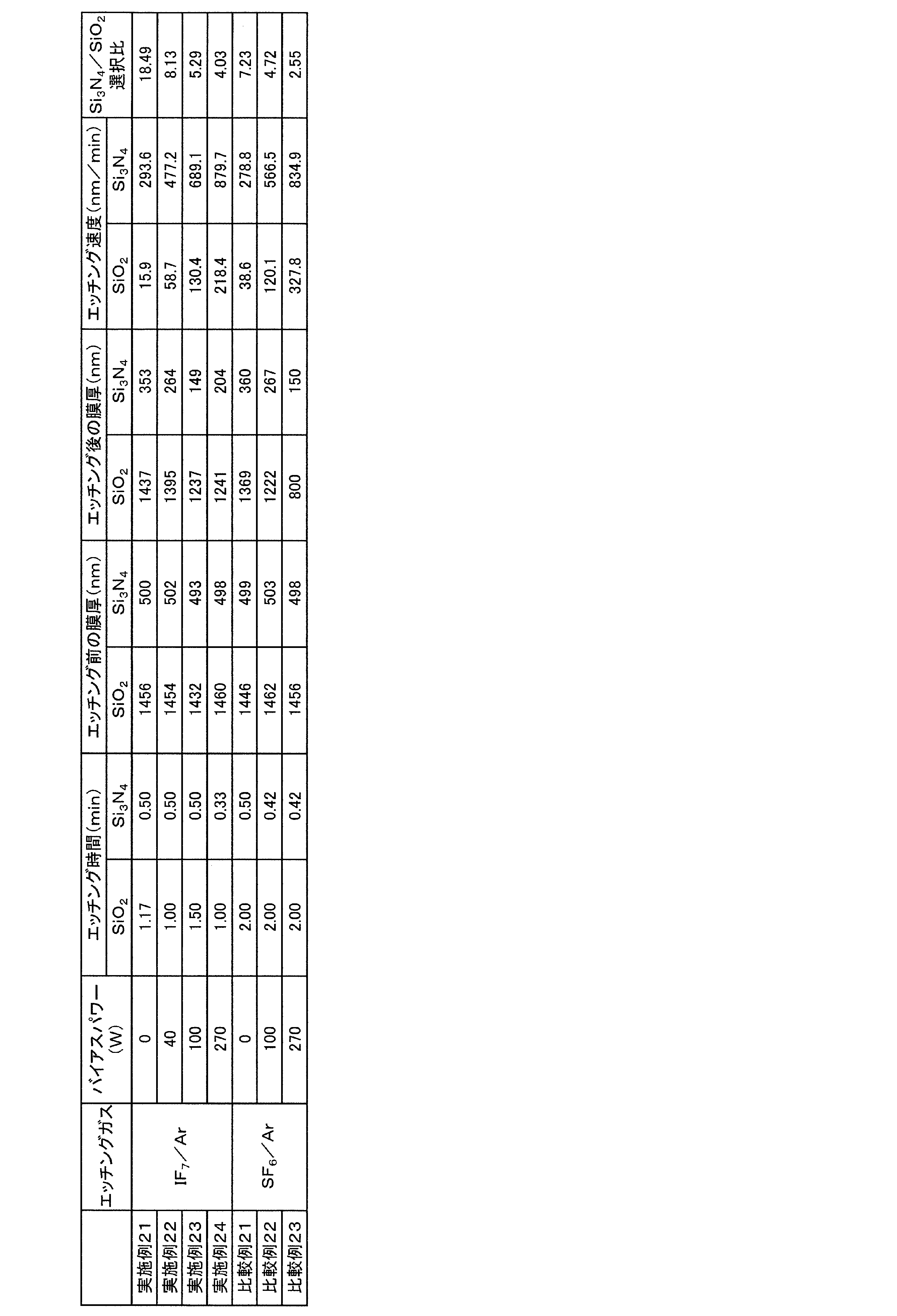
エッチングガスを六フッ化硫黄ガスとアルゴンの混合ガス(エッチングガス中の六フッ化硫黄の濃度は20体積%である)とした点と、プロセス圧力を5Paとした点と、バイアスパワーを表3に示す通り変更した点以外は、実施例1と同様にしてプラズマエッチングを行い、窒化シリコン膜及び酸化シリコン膜の各エッチング速度、並びに、酸化シリコン膜のエッチング速度に対する窒化シリコン膜のエッチング速度の比を算出した。結果を表3に示す。
プロセス圧力を3Paとした点と、エッチングガス中の七フッ化ヨウ素の濃度を表4に示す通り変更した点以外は、実施例1と同様にしてプラズマエッチングを行い、窒化シリコン膜及び酸化シリコン膜の各エッチング速度、並びに、酸化シリコン膜のエッチング速度に対する窒化シリコン膜のエッチング速度の比を算出した。結果を表4に示す。
さらに、表3及び図4のグラフから、いずれのバイアスパワーにおいても、七フッ化ヨウ素を含有するエッチングガスの方が、六フッ化硫黄を含有するエッチングガスよりも、酸化シリコン膜のエッチング速度に対する窒化シリコン膜のエッチング速度の比が大きく、酸化シリコン膜に対して窒化シリコン膜が選択的にエッチングされていることが分かる。そして、Si3N4/SiO2選択比は、バイアスパワーが低いほど向上することが分かる。
2・・・下部電極
3・・・七フッ化ヨウ素ガス供給部
4・・・不活性ガス供給部
11・・・エッチングガス供給用配管
12・・・不活性ガス供給用配管
13・・・真空ポンプ
14・・・圧力計
15・・・RFコイル
16・・・センサー
17・・・分光器
20・・・基板
Claims (7)
- 七フッ化ヨウ素を含有するエッチングガスをプラズマ化して得られたプラズマを用いて、基板上に形成された窒化シリコン膜をエッチングするエッチング工程を備えるプラズマエッチング方法。
- 前記基板上には前記窒化シリコン膜とともに酸化シリコン膜が形成されており、前記窒化シリコン膜とともに前記酸化シリコン膜をエッチングする請求項1に記載のプラズマエッチング方法。
- 前記窒化シリコン膜のエッチング速度が前記酸化シリコン膜のエッチング速度よりも大きい請求項2に記載のプラズマエッチング方法。
- 前記酸化シリコン膜のエッチング速度に対する前記窒化シリコン膜のエッチング速度の比が2以上70以下である請求項3に記載のプラズマエッチング方法。
- 前記エッチングガスが七フッ化ヨウ素と不活性ガスとを含有する混合ガスである請求項1~4のいずれか一項に記載のプラズマエッチング方法。
- 1Pa以上10Pa以下のプロセス圧力下でエッチングを行う請求項1~5のいずれか一項に記載のプラズマエッチング方法。
- 前記基板を支持する下部電極に0W以上1500W以下のバイアスパワーを印加しつつエッチングを行う請求項1~6のいずれか一項に記載のプラズマエッチング方法。
Priority Applications (8)
| Application Number | Priority Date | Filing Date | Title |
|---|---|---|---|
| EP20826514.0A EP3989682A4 (en) | 2019-06-18 | 2020-05-22 | PLASMA ETCH PROCESS |
| JP2021527495A JP7537430B2 (ja) | 2019-06-18 | 2020-05-22 | プラズマエッチング方法 |
| CN202080040563.7A CN113906829A (zh) | 2019-06-18 | 2020-05-22 | 等离子体蚀刻方法 |
| SG11202112469XA SG11202112469XA (en) | 2019-06-18 | 2020-05-22 | Plasma etching method |
| KR1020217035377A KR20210143313A (ko) | 2019-06-18 | 2020-05-22 | 플라즈마 에칭 방법 |
| US17/611,754 US20220254607A1 (en) | 2019-06-18 | 2020-05-22 | Plasma etching method |
| IL287744A IL287744B1 (en) | 2019-06-18 | 2021-10-31 | Plasma etching method |
| JP2024090814A JP2024113055A (ja) | 2019-06-18 | 2024-06-04 | プラズマエッチング方法 |
Applications Claiming Priority (2)
| Application Number | Priority Date | Filing Date | Title |
|---|---|---|---|
| JP2019113023 | 2019-06-18 | ||
| JP2019-113023 | 2019-06-18 |
Publications (1)
| Publication Number | Publication Date |
|---|---|
| WO2020255631A1 true WO2020255631A1 (ja) | 2020-12-24 |
Family
ID=74037084
Family Applications (1)
| Application Number | Title | Priority Date | Filing Date |
|---|---|---|---|
| PCT/JP2020/020404 Ceased WO2020255631A1 (ja) | 2019-06-18 | 2020-05-22 | プラズマエッチング方法 |
Country Status (9)
| Country | Link |
|---|---|
| US (1) | US20220254607A1 (ja) |
| EP (1) | EP3989682A4 (ja) |
| JP (2) | JP7537430B2 (ja) |
| KR (1) | KR20210143313A (ja) |
| CN (1) | CN113906829A (ja) |
| IL (1) | IL287744B1 (ja) |
| SG (1) | SG11202112469XA (ja) |
| TW (1) | TWI799711B (ja) |
| WO (1) | WO2020255631A1 (ja) |
Cited By (2)
| Publication number | Priority date | Publication date | Assignee | Title |
|---|---|---|---|---|
| JP2024536314A (ja) * | 2021-10-07 | 2024-10-04 | アプライド マテリアルズ インコーポレイテッド | マイクロ波プラズマを用いた窒化ケイ素の低温選択エッチング |
| WO2026070784A1 (ja) * | 2024-09-26 | 2026-04-02 | 株式会社レゾナック | プラズマエッチング方法 |
Families Citing this family (1)
| Publication number | Priority date | Publication date | Assignee | Title |
|---|---|---|---|---|
| JP2021053018A (ja) * | 2019-09-30 | 2021-04-08 | 株式会社三洋物産 | 遊技機 |
Citations (3)
| Publication number | Priority date | Publication date | Assignee | Title |
|---|---|---|---|---|
| JP2004039740A (ja) * | 2002-07-01 | 2004-02-05 | Research Institute Of Innovative Technology For The Earth | フッ素ガスによるクリーニング機構を備えたcvd装置およびcvd装置のフッ素ガスによるクリーニング方法 |
| WO2015016149A1 (ja) * | 2013-07-29 | 2015-02-05 | 株式会社日立国際電気 | 基板処理装置、半導体装置の製造方法および記録媒体 |
| WO2018225661A1 (ja) * | 2017-06-08 | 2018-12-13 | 昭和電工株式会社 | エッチング方法 |
Family Cites Families (6)
| Publication number | Priority date | Publication date | Assignee | Title |
|---|---|---|---|---|
| US157940A (en) | 1874-12-22 | Improvement in bale-ties | ||
| JPS6012779B2 (ja) * | 1976-04-28 | 1985-04-03 | 株式会社日立製作所 | 半導体装置の製造方法 |
| WO1999034428A1 (en) * | 1997-12-31 | 1999-07-08 | Alliedsignal Inc. | Method of etching and cleaning using interhalogen compounds |
| US20180286707A1 (en) * | 2017-03-30 | 2018-10-04 | Lam Research Corporation | Gas additives for sidewall passivation during high aspect ratio cryogenic etch |
| US10586710B2 (en) * | 2017-09-01 | 2020-03-10 | Tokyo Electron Limited | Etching method |
| JP2020068221A (ja) * | 2018-10-22 | 2020-04-30 | 東京エレクトロン株式会社 | エッチング方法及びプラズマ処理装置 |
-
2020
- 2020-05-22 CN CN202080040563.7A patent/CN113906829A/zh active Pending
- 2020-05-22 SG SG11202112469XA patent/SG11202112469XA/en unknown
- 2020-05-22 KR KR1020217035377A patent/KR20210143313A/ko not_active Ceased
- 2020-05-22 WO PCT/JP2020/020404 patent/WO2020255631A1/ja not_active Ceased
- 2020-05-22 JP JP2021527495A patent/JP7537430B2/ja active Active
- 2020-05-22 EP EP20826514.0A patent/EP3989682A4/en active Pending
- 2020-05-22 US US17/611,754 patent/US20220254607A1/en active Pending
- 2020-06-03 TW TW109118596A patent/TWI799711B/zh active
-
2021
- 2021-10-31 IL IL287744A patent/IL287744B1/en unknown
-
2024
- 2024-06-04 JP JP2024090814A patent/JP2024113055A/ja not_active Withdrawn
Patent Citations (3)
| Publication number | Priority date | Publication date | Assignee | Title |
|---|---|---|---|---|
| JP2004039740A (ja) * | 2002-07-01 | 2004-02-05 | Research Institute Of Innovative Technology For The Earth | フッ素ガスによるクリーニング機構を備えたcvd装置およびcvd装置のフッ素ガスによるクリーニング方法 |
| WO2015016149A1 (ja) * | 2013-07-29 | 2015-02-05 | 株式会社日立国際電気 | 基板処理装置、半導体装置の製造方法および記録媒体 |
| WO2018225661A1 (ja) * | 2017-06-08 | 2018-12-13 | 昭和電工株式会社 | エッチング方法 |
Non-Patent Citations (1)
| Title |
|---|
| See also references of EP3989682A4 * |
Cited By (4)
| Publication number | Priority date | Publication date | Assignee | Title |
|---|---|---|---|---|
| JP2024536314A (ja) * | 2021-10-07 | 2024-10-04 | アプライド マテリアルズ インコーポレイテッド | マイクロ波プラズマを用いた窒化ケイ素の低温選択エッチング |
| US12438005B2 (en) | 2021-10-07 | 2025-10-07 | Applied Materials, Inc. | Low temperature selective etching of silicon nitride using microwave plasma |
| JP7826465B2 (ja) | 2021-10-07 | 2026-03-09 | アプライド マテリアルズ インコーポレイテッド | マイクロ波プラズマを用いた窒化ケイ素の低温選択エッチング |
| WO2026070784A1 (ja) * | 2024-09-26 | 2026-04-02 | 株式会社レゾナック | プラズマエッチング方法 |
Also Published As
| Publication number | Publication date |
|---|---|
| US20220254607A1 (en) | 2022-08-11 |
| EP3989682A4 (en) | 2022-08-03 |
| IL287744B1 (en) | 2026-03-01 |
| IL287744A (en) | 2021-12-01 |
| JP2024113055A (ja) | 2024-08-21 |
| JPWO2020255631A1 (ja) | 2020-12-24 |
| JP7537430B2 (ja) | 2024-08-21 |
| TWI799711B (zh) | 2023-04-21 |
| TW202109665A (zh) | 2021-03-01 |
| KR20210143313A (ko) | 2021-11-26 |
| CN113906829A (zh) | 2022-01-07 |
| EP3989682A1 (en) | 2022-04-27 |
| SG11202112469XA (en) | 2021-12-30 |
Similar Documents
| Publication | Publication Date | Title |
|---|---|---|
| JP4579611B2 (ja) | ドライエッチング方法 | |
| US10424463B2 (en) | Oxide etch selectivity systems and methods | |
| US9478432B2 (en) | Silicon oxide selective removal | |
| JP2024113055A (ja) | プラズマエッチング方法 | |
| KR20130047663A (ko) | 플라즈마 에칭 방법 | |
| TW201842603A (zh) | 用於遠端電漿監控之光學放射頻譜儀(oes) | |
| JP2010177480A (ja) | プラズマ処理装置およびプラズマ処理方法 | |
| WO2020195559A1 (ja) | ドライエッチング方法及び半導体デバイスの製造方法 | |
| JP2018522417A (ja) | 調節可能な遠隔解離 | |
| US9093261B2 (en) | Method of manufacturing semiconductor device | |
| US6815369B2 (en) | Method for monitoring deposition reaction during processing the surface of a semiconductor substrate | |
| JP2001196355A (ja) | 半導体装置の製造方法 | |
| JP2002134472A (ja) | エッチング方法、エッチング装置および半導体装置の製造方法 | |
| US20250118556A1 (en) | Method for forming deposition film | |
| EP4207251B1 (en) | Plasma etching method and method for manufacturing semiconductor element | |
| JPWO2020129725A1 (ja) | ハロゲンフッ化物によるエッチング方法、半導体の製造方法 | |
| WO2026070784A1 (ja) | プラズマエッチング方法 | |
| CN115020220B (zh) | 硅氧化物膜层表面氟元素处理方法、刻蚀方法 | |
| JP2011211135A (ja) | プラズマ処理方法 | |
| WO2018230373A1 (ja) | プラズマ処理装置のシーズニング方法及びプラズマエッチング方法 | |
| JP2016213404A (ja) | プラズマエッチング方法 |
Legal Events
| Date | Code | Title | Description |
|---|---|---|---|
| 121 | Ep: the epo has been informed by wipo that ep was designated in this application |
Ref document number: 20826514 Country of ref document: EP Kind code of ref document: A1 |
|
| ENP | Entry into the national phase |
Ref document number: 2021527495 Country of ref document: JP Kind code of ref document: A |
|
| ENP | Entry into the national phase |
Ref document number: 20217035377 Country of ref document: KR Kind code of ref document: A |
|
| NENP | Non-entry into the national phase |
Ref country code: DE |
|
| ENP | Entry into the national phase |
Ref document number: 2020826514 Country of ref document: EP Effective date: 20220118 |
|
| WWR | Wipo information: refused in national office |
Ref document number: 1020217035377 Country of ref document: KR |
|
| WWC | Wipo information: continuation of processing after refusal or withdrawal |
Ref document number: 1020217035377 Country of ref document: KR |