WO2020255793A1 - 暗号鍵生成装置、暗号鍵生成方法 - Google Patents
暗号鍵生成装置、暗号鍵生成方法 Download PDFInfo
- Publication number
- WO2020255793A1 WO2020255793A1 PCT/JP2020/022668 JP2020022668W WO2020255793A1 WO 2020255793 A1 WO2020255793 A1 WO 2020255793A1 JP 2020022668 W JP2020022668 W JP 2020022668W WO 2020255793 A1 WO2020255793 A1 WO 2020255793A1
- Authority
- WO
- WIPO (PCT)
- Prior art keywords
- key
- encryption
- random number
- image data
- image
- Prior art date
- Legal status (The legal status is an assumption and is not a legal conclusion. Google has not performed a legal analysis and makes no representation as to the accuracy of the status listed.)
- Ceased
Links
Images













Classifications
-
- H—ELECTRICITY
- H04—ELECTRIC COMMUNICATION TECHNIQUE
- H04L—TRANSMISSION OF DIGITAL INFORMATION, e.g. TELEGRAPHIC COMMUNICATION
- H04L9/00—Cryptographic mechanisms or cryptographic arrangements for secret or secure communications; Network security protocols
- H04L9/08—Key distribution or management, e.g. generation, sharing or updating, of cryptographic keys or passwords
- H04L9/0816—Key establishment, i.e. cryptographic processes or cryptographic protocols whereby a shared secret becomes available to two or more parties, for subsequent use
- H04L9/0819—Key transport or distribution, i.e. key establishment techniques where one party creates or otherwise obtains a secret value, and securely transfers it to the other(s)
- H04L9/0825—Key transport or distribution, i.e. key establishment techniques where one party creates or otherwise obtains a secret value, and securely transfers it to the other(s) using asymmetric-key encryption or public key infrastructure [PKI], e.g. key signature or public key certificates
-
- G—PHYSICS
- G06—COMPUTING OR CALCULATING; COUNTING
- G06F—ELECTRIC DIGITAL DATA PROCESSING
- G06F7/00—Methods or arrangements for processing data by operating upon the order or content of the data handled
- G06F7/58—Random or pseudo-random number generators
- G06F7/588—Random number generators, i.e. based on natural stochastic processes
-
- G—PHYSICS
- G06—COMPUTING OR CALCULATING; COUNTING
- G06F—ELECTRIC DIGITAL DATA PROCESSING
- G06F21/00—Security arrangements for protecting computers, components thereof, programs or data against unauthorised activity
- G06F21/60—Protecting data
- G06F21/602—Providing cryptographic facilities or services
-
- G—PHYSICS
- G06—COMPUTING OR CALCULATING; COUNTING
- G06F—ELECTRIC DIGITAL DATA PROCESSING
- G06F21/00—Security arrangements for protecting computers, components thereof, programs or data against unauthorised activity
- G06F21/60—Protecting data
- G06F21/64—Protecting data integrity, e.g. using checksums, certificates or signatures
-
- G—PHYSICS
- G09—EDUCATION; CRYPTOGRAPHY; DISPLAY; ADVERTISING; SEALS
- G09C—CIPHERING OR DECIPHERING APPARATUS FOR CRYPTOGRAPHIC OR OTHER PURPOSES INVOLVING THE NEED FOR SECRECY
- G09C1/00—Apparatus or methods whereby a given sequence of signs, e.g. an intelligible text, is transformed into an unintelligible sequence of signs by transposing the signs or groups of signs or by replacing them by others according to a predetermined system
-
- H—ELECTRICITY
- H04—ELECTRIC COMMUNICATION TECHNIQUE
- H04L—TRANSMISSION OF DIGITAL INFORMATION, e.g. TELEGRAPHIC COMMUNICATION
- H04L9/00—Cryptographic mechanisms or cryptographic arrangements for secret or secure communications; Network security protocols
- H04L9/06—Cryptographic mechanisms or cryptographic arrangements for secret or secure communications; Network security protocols the encryption apparatus using shift registers or memories for block-wise or stream coding, e.g. DES systems or RC4; Hash functions; Pseudorandom sequence generators
- H04L9/0643—Hash functions, e.g. MD5, SHA, HMAC or f9 MAC
-
- H—ELECTRICITY
- H04—ELECTRIC COMMUNICATION TECHNIQUE
- H04L—TRANSMISSION OF DIGITAL INFORMATION, e.g. TELEGRAPHIC COMMUNICATION
- H04L9/00—Cryptographic mechanisms or cryptographic arrangements for secret or secure communications; Network security protocols
- H04L9/06—Cryptographic mechanisms or cryptographic arrangements for secret or secure communications; Network security protocols the encryption apparatus using shift registers or memories for block-wise or stream coding, e.g. DES systems or RC4; Hash functions; Pseudorandom sequence generators
- H04L9/065—Encryption by serially and continuously modifying data stream elements, e.g. stream cipher systems, RC4, SEAL or A5/3
- H04L9/0656—Pseudorandom key sequence combined element-for-element with data sequence, e.g. one-time-pad [OTP] or Vernam's cipher
- H04L9/0662—Pseudorandom key sequence combined element-for-element with data sequence, e.g. one-time-pad [OTP] or Vernam's cipher with particular pseudorandom sequence generator
-
- H—ELECTRICITY
- H04—ELECTRIC COMMUNICATION TECHNIQUE
- H04L—TRANSMISSION OF DIGITAL INFORMATION, e.g. TELEGRAPHIC COMMUNICATION
- H04L9/00—Cryptographic mechanisms or cryptographic arrangements for secret or secure communications; Network security protocols
- H04L9/08—Key distribution or management, e.g. generation, sharing or updating, of cryptographic keys or passwords
- H04L9/0861—Generation of secret information including derivation or calculation of cryptographic keys or passwords
- H04L9/0869—Generation of secret information including derivation or calculation of cryptographic keys or passwords involving random numbers or seeds
-
- H—ELECTRICITY
- H04—ELECTRIC COMMUNICATION TECHNIQUE
- H04L—TRANSMISSION OF DIGITAL INFORMATION, e.g. TELEGRAPHIC COMMUNICATION
- H04L9/00—Cryptographic mechanisms or cryptographic arrangements for secret or secure communications; Network security protocols
- H04L9/32—Cryptographic mechanisms or cryptographic arrangements for secret or secure communications; Network security protocols including means for verifying the identity or authority of a user of the system or for message authentication, e.g. authorization, entity authentication, data integrity or data verification, non-repudiation, key authentication or verification of credentials
- H04L9/3236—Cryptographic mechanisms or cryptographic arrangements for secret or secure communications; Network security protocols including means for verifying the identity or authority of a user of the system or for message authentication, e.g. authorization, entity authentication, data integrity or data verification, non-repudiation, key authentication or verification of credentials using cryptographic hash functions
- H04L9/3239—Cryptographic mechanisms or cryptographic arrangements for secret or secure communications; Network security protocols including means for verifying the identity or authority of a user of the system or for message authentication, e.g. authorization, entity authentication, data integrity or data verification, non-repudiation, key authentication or verification of credentials using cryptographic hash functions involving non-keyed hash functions, e.g. modification detection codes [MDCs], MD5, SHA or RIPEMD
-
- H—ELECTRICITY
- H04—ELECTRIC COMMUNICATION TECHNIQUE
- H04L—TRANSMISSION OF DIGITAL INFORMATION, e.g. TELEGRAPHIC COMMUNICATION
- H04L9/00—Cryptographic mechanisms or cryptographic arrangements for secret or secure communications; Network security protocols
- H04L9/32—Cryptographic mechanisms or cryptographic arrangements for secret or secure communications; Network security protocols including means for verifying the identity or authority of a user of the system or for message authentication, e.g. authorization, entity authentication, data integrity or data verification, non-repudiation, key authentication or verification of credentials
- H04L9/3247—Cryptographic mechanisms or cryptographic arrangements for secret or secure communications; Network security protocols including means for verifying the identity or authority of a user of the system or for message authentication, e.g. authorization, entity authentication, data integrity or data verification, non-repudiation, key authentication or verification of credentials involving digital signatures
-
- H—ELECTRICITY
- H04—ELECTRIC COMMUNICATION TECHNIQUE
- H04L—TRANSMISSION OF DIGITAL INFORMATION, e.g. TELEGRAPHIC COMMUNICATION
- H04L9/00—Cryptographic mechanisms or cryptographic arrangements for secret or secure communications; Network security protocols
- H04L9/50—Cryptographic mechanisms or cryptographic arrangements for secret or secure communications; Network security protocols using hash chains, e.g. blockchains or hash trees
-
- H—ELECTRICITY
- H04—ELECTRIC COMMUNICATION TECHNIQUE
- H04N—PICTORIAL COMMUNICATION, e.g. TELEVISION
- H04N23/00—Cameras or camera modules comprising electronic image sensors; Control thereof
- H04N23/80—Camera processing pipelines; Components thereof
-
- H—ELECTRICITY
- H04—ELECTRIC COMMUNICATION TECHNIQUE
- H04N—PICTORIAL COMMUNICATION, e.g. TELEVISION
- H04N5/00—Details of television systems
- H04N5/76—Television signal recording
- H04N5/91—Television signal processing therefor
Definitions
- This technology relates to a cryptographic key generator and a cryptographic key generation method, and particularly to a technical field related to cryptographic key generation for digital signatures.
- the electronic signature method is widely used to detect falsification of data.
- the sender of the data generates a private key and a public key used for encrypting the hash value.
- the sender transmits the target data for falsification detection, the hash value of the target data encrypted with the private key, and the public key to the recipient.
- the recipient calculates the hash value of the received target data, decrypts the hash value encrypted with the private key by the received public key, and determines whether or not the data has been tampered with based on whether or not the hash values match. can do.
- Patent Document 1 discloses a technique for detecting falsification of captured image data based on electronic signature information.
- the private key used for encrypting the hash value is generated based on the pseudo-random number generated by the software, and there is a risk that the private key is decrypted and duplicated. If the private key is duplicated, it becomes possible for the recipient to erroneously determine that the tampered data has not been tampered with. That is, increasing the risk of decrypting the private key for electronic signature leads to a decrease in tampering detection performance.
- This technology was made in view of the above circumstances, and aims to make it difficult to decipher the private key for electronic signatures and improve the tampering detection performance.
- the encryption key generator according to the present technology is based on a photoelectric random number which is a random number obtained by photoelectric conversion by an array sensor in which a plurality of pixels having visible light or invisible light light receiving elements are arranged one-dimensionally or two-dimensionally. It is equipped with a key generator that generates a private key for electronic signature. This makes it possible to make it more difficult to decipher the private key for digital signature than when using a pseudo-random number.
- the key generation unit is configured to generate a private key for electronic signature of image data.
- the key generation unit is configured to generate a private key for electronic signature of image data.
- the key generation unit is configured to generate a private key for electronic signature of image data obtained by imaging with the array sensor.
- the array sensor for obtaining image data is shared with the array sensor for obtaining photoelectric random numbers.
- an encryption unit that encrypts image data obtained by imaging with the array sensor and the image data encrypted by the encryption unit are used as an external device. It is conceivable that the configuration includes a transmission processing unit that performs transmission processing. This makes it possible to securely transmit the image data as the target data of the electronic signature.
- the encryption unit has a configuration in which the image data is encrypted by the encryption key generated based on the photoelectric random number. As a result, it is possible to make it more difficult to decrypt the encryption key than when using a pseudo-random number for encrypting the image data.
- the encryption unit encrypts the image data so that the decipherable image range differs depending on the level of the decryption key used for decrypting the image data, and transmits the image data.
- the processing unit is encrypted with a decryption key at the same level as the decryption key possessed by the external device in response to the external device making a transmission request for the image data encrypted by the encryption unit.
- the image data is decrypted, a hash value of the decoded image data is generated, and the hash value encrypted by the private key and the encrypted image data are transmitted to the external device. Can be considered.
- the hash value is generated when the transmission request is made. It is only necessary to perform the decryption key level of the receiving device in which the above is performed, and it is not necessary to generate the hash value of each level at once when recording the image data (captured image data).
- the key generation unit is configured to generate a secret key for an electronic signature in a blockchain system based on the photoelectric random number. This makes it possible to make it more difficult to decipher the private key for digital signature in the blockchain system than when using a pseudo-random number.
- the above-mentioned encryption key generation device may be configured to include a verifier selection unit that selects contract verification workers in a smart contract system based on the photoelectric random numbers. This makes it possible to make the random numbers used for selecting the contract verification worker more difficult to decipher than when using pseudo-random numbers.
- the encryption key generation device includes a representative selection unit that selects a representative from the users of the service by DAPPs based on the photoelectric random number. This makes it possible to make it more difficult to decipher the random numbers used for selecting representatives from the DApps service recipients than when using pseudo-random numbers.
- the key generation unit is configured to acquire the value of the electric signal for each pixel obtained by the photoelectric conversion as the photoelectric random number and generate the secret key. Is possible. This makes it possible to generate an electronically signed private key that is difficult to decipher.
- the key generation unit sets at least a part of the value of the electric signal for each pixel at a pixel position different from the pixel position from which the value of the electric signal is obtained. It is conceivable that the secret key is generated based on the photoelectric random number in the format assigned to. As a result, it is difficult to decipher the electronic signature private key as compared with the case of using a photoelectric random number in which the value of the electric signal for each pixel is directly assigned to the pixel position where the value of the electric signal is obtained.
- the encryption key generation device is configured to include an erasing processing unit that performs processing for erasing the image data that is the source of the photoelectric random number from the memory after the photoelectric random number is generated. Can be considered. As a result, it is possible to prevent the image that is the source of the photoelectric random number from leaking out and the photoelectric random number from being estimated.
- the encryption key generation device includes a regeneration processing unit that performs processing for regenerating the photoelectric random number in response to the detection of unauthorized access from the outside of the encryption key generation device. Is conceivable. As a result, when an unauthorized access from the outside is detected, the digital signature private key can be updated based on the regenerated photoelectric random number.
- the encryption key generation method is a random number obtained by an information processing apparatus based on photoelectric conversion by an array sensor in which a plurality of pixels having visible or invisible light receiving elements are arranged one-dimensionally or two-dimensionally. This is an encryption key generation method for generating a private key for an electronic signature based on a photoelectric random number.
- First Embodiment> [1-1. Configuration of digital signature system] [1-2. Configuration of imaging device] [1-3. Receiver configuration] [1-4. Random numbers used for encryption] [1-5. About the signal to be encrypted] [1-6. About tamper resistance] [1-7. Processing procedure for image encryption] [1-8. About key delivery for image decoding] [1-9. Falsification detection method as the first embodiment] ⁇ 2.
- Second Embodiment> [2-1. Image encryption method of the second embodiment] [2-2. Processing procedure for image encryption] [2-3. Falsification detection method as the second embodiment] [2-4. Recipient's public key verification process] [2-5. Confirmation process of the sender's digital signature public key] ⁇ 3.
- Third Embodiment> ⁇ 4. Modification example> ⁇ 5. Summary of embodiments> ⁇ 6. This technology>
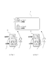
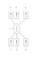
- FIG. 1 is a block diagram showing a schematic configuration example of the electronic signature system according to the first embodiment.
- the electronic signature system includes an imaging device 1, a network 2, and a plurality of receiving devices 3.
- the image pickup device 1 is an embodiment of an encryption key generation device according to the present technology, and obtains image data (captured image data) as digital data by performing image pickup with an image sensor.
- the target data of the electronic signature is the image image data captured by the image pickup device 1.
- Each receiving device 3 is a device that receives the target data of the electronic signature, that is, the image image data captured by the imaging device 1 in this example, and may perform data communication with the imaging device 1 via, for example, a network 2 as the Internet. It is configured to be possible.
- the imaging device 1 when transmitting the captured image data to the receiving device 3, the imaging device 1 generates a private key for electronic signature and a public key based on the private key, and also regarding the captured image data to be transmitted. The hash value of is calculated, and the hash value is encrypted with the private key. Then, the imaging device 1 transmits the encrypted hash value, the captured image data to be transmitted, and the public key to the receiving device 3. The receiving device 3 performs falsification detection processing on the received captured image data based on these data transmitted from the imaging device 1. The process for detecting falsification in this embodiment will be described later.
- the image pickup device 1 when the image pickup device 1 transmits the captured image data to the receiving device 3, the captured image data is encrypted in order to improve confidentiality.
- the image pickup apparatus 1 of the present embodiment executes various processes for encrypting the captured image data in this way.
- FIG. 2 is a block diagram showing an example of the internal configuration of the image pickup apparatus 1.
- the image pickup apparatus 1 includes an image pickup sensor unit 10, an image processor 21, a sensor unit 22, a control unit 23, a memory unit 24, and a communication unit 25.
- the image pickup sensor unit 10 receives light incident on each pixel through a camera optical system (not shown) provided in the image pickup device 1, and performs photoelectric conversion to obtain captured image data.
- the imaging sensor unit 10 has a configuration part as an image sensor device, a memory device such as a DRAM (Dynamic Random Access Memory), and an AI (artificial intelligence) functional processor as hardware. doing. Then, these three are integrated into a three-layer laminated structure, one layer is a so-called flat configuration, or two layers (for example, the memory device and the AI function processor are the same layer) laminated structure. It is said to be a device of.
- the image sensor unit 10 of this example is provided with an object detection function by image analysis, and is a device that can be called an intelligent array sensor.
- the imaging sensor unit 10 includes an array sensor 12, an amplitude control circuit 19, an ADC (Analog to Digital Converter) / pixel selector 13, a buffer 14, a logic unit 15, a memory 16, an interface unit 17, and a calculation unit 18. have.
- ADC Analog to Digital Converter
- the array sensor 12 is configured by arranging a plurality of pixels having visible or invisible light receiving elements in one or two dimensions. For example, a large number of pixels are arranged two-dimensionally in the row direction and the column direction, and a two-dimensional image signal is output by photoelectric conversion in the light receiving element of each pixel.
- the amplitude control circuit 19 controls the amplitude of the electrical signal (analog signal) photoelectrically converted by the array sensor 12.
- the amplitude control circuit 19 is configured so that the amplification factor can be changed based on an instruction from the calculation unit 18, but this point will be described later.
- An electric signal photoelectrically converted by the array sensor 12 is input to the ADC / pixel selector 13 via the amplitude control circuit 19.
- the ADC / pixel selector 13 digitizes an electrical signal as an input analog signal and outputs an image signal (image data) as digital data. Further, the ADC / pixel selector 13 has a pixel selection function for the pixels (light receiving elements) of the array sensor 12. As a result, it is possible to acquire the photoelectric conversion signal and output it as digital data only for the selected pixel in the array sensor 12. That is, the ADC / pixel selector 13 normally outputs the photoelectric conversion signal to digital data for all the effective pixels constituting the image of one frame, but outputs the photoelectric conversion signal to digital data only for the selected pixel. It is also possible to do it.
- Image data is acquired in frame units by the ADC / pixel selector 13, and the image data of each frame is temporarily stored in the buffer 14, read out at an appropriate timing, and used for processing by the logic unit 15.
- the logic unit 15 performs various necessary signal processing (image processing) on each input frame image signal. For example, it is assumed that the logic unit 15 adjusts the image quality by processing such as color correction, gamma correction, color gradation processing, gain processing, and contour enhancement processing. Further, it is assumed that the logic unit 15 performs processing for changing the data size, such as data compression processing, resolution conversion, and frame rate conversion. Parameters used for each process are set for each process performed by the logic unit 15. For example, there are setting values such as color and brightness correction coefficients, gain values, compression rates, and frame rates. The logic unit 15 performs necessary processing using the parameters set for each processing. In the present embodiment, the calculation unit 18 may set these parameters.
- the image data processed by the logic unit 15 is stored in a memory 16 configured by, for example, a DRAM or the like.
- the image data stored in the memory 16 is transmitted and output to the image processor 21 or the like by the interface unit 17 at a required timing.
- the image processor 21 performs image analysis and image recognition processing on the image data transmitted from the image pickup sensor unit 10, and executes necessary object detection and the like.
- the image processor 21 can also refer to the detection information of the sensor unit 22.
- the calculation unit 18 is configured as, for example, one AI processor.
- a keyframe selection unit 81 As an executable calculation function, a keyframe selection unit 81, an object area recognition unit 82, a class identification unit 83, a parameter selection unit 84, an encryption control unit 85, and an unauthorized access detection unit 86 are provided as shown in the figure. Note that these arithmetic functions may be configured by a plurality of processors.
- the key frame selection unit 81 performs a process of selecting a key frame from the frames of image data as a moving image according to a predetermined algorithm or instruction.
- the object area recognition unit 82 detects an area of an object that is a candidate for detection and an image of an object to be detected with respect to a frame of image data that is photoelectrically converted by the array sensor 12 and acquired by the ADC / pixel selector 13.
- the recognition process of the area (bounding box) surrounding the object in the (frame) is performed.
- An object detected from an image signal is an object that can be detected for the purpose of recognition from an image. What kind of object is targeted for detection differs depending on the detection purpose, processing capacity, application type, etc. of the image sensor unit 10 and the image processor 21, but all objects are the objects to be detected here. May be said.
- the object area recognition unit 82 in this example executes a process of calculating ROI (Region of Interest) which is area information indicating an area (area of interest) to be processed based on the bounding box.
- ROI Region of Interest
- the class identification unit 83 classifies the objects detected by the object area recognition unit 82.
- a class is information that represents a category of an object, such as "person,”"car,””airplane,””ship,””truck,””bird,””cat,””dog,””deer,””frog,” or “horse.”
- the objects to be detected are classified into classes.
- the parameter selection unit 84 stores the parameters for signal processing corresponding to each class, and selects one or a plurality of corresponding parameters by using the class of the detected object identified by the class identification unit 83, the bounding box, or the like. To do. Then, one or a plurality of parameters are set in the logic unit 15.
- the processing of various functions by the calculation unit 18 described above is a processing that is not normally performed in the image sensor, and in the present embodiment, object detection, class recognition, and control based on these are executed in the image sensor. ..
- object detection, class recognition, and control based on these are executed in the image sensor. ..
- the encryption control unit 85 controls the image signal obtained by imaging with the array sensor 12 so as to be encrypted. A specific example of the processing performed by the encryption control unit 85 for encrypting such an image signal will be described again.
- the unauthorized access detection unit 86 detects unauthorized access from the outside of the image pickup device 1. Specifically, the unauthorized access detection unit 86 in this example detects unauthorized access from the outside to the data stored in the memory 16. When the unauthorized access detection unit 86 detects an unauthorized access, the unauthorized access detection unit 86 records the log information (for example, information indicating the detection date and time and the type of the unauthorized access) in a predetermined area of the memory 16.
- the log information for example, information indicating the detection date and time and the type of the unauthorized access
- the control unit 23 includes, for example, a microcomputer equipped with a CPU (Central Processing Unit), a ROM (Read Only Memory), and a RAM (Random Access Memory), and the CPU is a program stored in the ROM, or a program. By executing various processes according to the program loaded in the RAM (Random Access Memory), the entire image pickup device 1 is controlled.
- the control unit 23 gives an instruction to the image pickup sensor unit 10 to control execution of various processes such as acquisition process of captured image data.
- the image processor 21 also controls the execution of various processes.
- the control unit 23 controls the writing and reading of various data to the memory unit 24.
- the memory unit 24 is a non-volatile storage device such as an HDD (Hard Disk Drive) or a flash memory device, and is a storage destination (recording destination) of various data such as captured image data obtained by the imaging sensor unit 10, for example. ). Further, the control unit 23 performs various data communications with the external device via the communication unit 25.
- the communication unit 25 is configured to be capable of performing data communication with an external device via the network 2 shown in FIG. In response to a request from the receiving device 3 shown in FIG. 1, the control unit 23 receives various data such as captured image data obtained by the imaging sensor unit 10 and stored in the memory unit 24 via the communication unit 25. It is possible to transmit to the device 3.
- control unit 23 executes various processes related to the electronic signature, and the processes will be described later.
- FIG. 3 is a block diagram showing an example of the internal configuration of the receiving device 3.
- the receiving device 3 includes a CPU 31, a ROM 32, a RAM 33, a bus 34, an input / output interface 35, an input unit 36, an output unit 37, a storage unit 38, and a communication unit 39.
- the CPU 31, ROM 32, and RAM 33 are connected to each other via the bus 34.
- An input / output interface 35 is also connected to the bus 34.
- the CPU 31 executes various processes according to the program stored in the ROM 32 or the program loaded from the storage unit 38 into the RAM 33.
- the RAM 33 also appropriately stores data and the like necessary for the CPU 31 to execute various processes.
- the input unit 36 comprehensively represents an operation input detection device such as a keyboard, a mouse, and a touch panel that detects operation input information from the user.
- the output unit 37 is composed of, for example, a display including an LCD (Liquid Crystal Display), an organic EL (Electroluminescence) panel, and a speaker.
- the storage unit 38 is composed of an HDD (Hard Disk Drive), a flash memory device, or the like.
- the communication unit 39 performs communication processing and inter-device communication via the network 2.
- the CPU 31 performs decryption of the captured image data in the encrypted state transmitted from the imaging device 1, falsification detection processing of the captured image data based on the electronic signature data, and the like. An example will be described later.
- the captured image data which is the target data of the electronic signature is encrypted, but in this example, a photoelectric random number is used for encryption of such the captured image data. .. That is, the encryption key used for encrypting the captured image data is generated based on the photoelectric random number.
- the photoelectric random number means a random number obtained based on the photoelectric conversion by the array sensor 12. Specifically, in this example, the value of the electric signal for each pixel obtained by the photoelectric conversion of the array sensor 12 is acquired as a photoelectric random number, and an encryption key is generated.
- FIG. 4 shows an example of a method of generating an encryption filter (encryption key) for image data based on a photoelectric random number.
- the left side in the figure illustrates the value of the electric signal for each pixel obtained by the photoelectric conversion of the array sensor 12.
- the photoelectric random number each pixel value (luminance value) of the image (still image) obtained by imaging with the array sensor 12 is used.
- a frame image captured to obtain a photoelectric random number in other words, a frame image that is the source of the photoelectric random number is referred to as a “seed frame”.
- the value of the electric signal for each pixel itself is not used as a photoelectric random number, but at least a part of the value of the electric signal for each pixel is used as the electric signal as illustrated on the right side of the figure.
- the pixel position is shuffled to generate a photoelectric random number.
- the photoelectric random number generated in this way is used as an encryption key (encryption filter) for the captured image data.
- the value of the electric signal for each pixel can be modulated by a predetermined algorithm and used. For example, a value obtained by multiplying the value of the electric signal for each pixel by a predetermined coefficient may be used as a photoelectric random number in a format assigned to the pixel.
- a method such as converting the value of the last few decimal places into an integer to obtain a photoelectric random number can be adopted.
- the random number used for encryption a pseudo-random number generated by software is often used.
- the pseudo-random number is generated by an algorithm for calculating a numerical value and cannot generate a true random number, there is a risk that the encryption key is decrypted and duplicated.
- the above-mentioned photoelectric random number can be a true random number, and it is possible to make it difficult to decrypt the encryption key by generating the encryption key based on the photoelectric random number.
- the read signal from the pixels of the array sensor 12 is encrypted so that the plaintext image signal is not stored in the memory.
- the amplitude control circuit 19 shown in FIG. 2 controls the amplitude of the read signal from the pixels of the array sensor 12 by the coefficient according to the encryption key (encryption filter) shown in FIG. By executing this, encryption of the read signal is realized.
- FIG. 5 is a diagram showing an image of encryption of the read signal by the amplitude control circuit 19.
- the read signal charge signal in this case
- the read signal for each pixel is amplitude-controlled at the analog signal stage in this way, and then A / D-converted by the ADC / pixel selector 13 to perform the buffer 14 and the logic unit 15. It is stored (recorded) in the memory 16 via.
- the encryption control unit 85 sets a coefficient corresponding to the encryption key in the above amplifier so that the read signal from each pixel in the array sensor 12 is encrypted.
- FIG. 5 is just an image diagram, and it is not essential that the amplifier is provided for each pixel in the amplitude control circuit 19.
- the amplifier included in the amplitude control circuit 19 may be one common to each pixel. In that case, the amplitude control for each pixel is performed by time division.
- FIG. 6 shows a configuration example of the image pickup apparatus 1 in the case where the read signal obtained by the digital signal is encrypted.
- the image pickup apparatus 1 in this case, in the image pickup sensor unit 10, instead of the amplitude control circuit 19, an amplitude control circuit 19A that controls the amplitude of the read signal converted into a digital signal by the ADC / pixel selector 13 is provided. ..
- the processing by the encryption control unit 85 is the same except that the setting target of the coefficient for each pixel according to the encryption key is changed from the amplitude control circuit 19 to the amplitude control circuit 19A. avoid.
- analog read signal is encrypted as described above, it is very difficult to illegally acquire the analog signal from the outside, so security can be improved.
- the analog read signal is encrypted
- the reproducibility of the image obtained by decrypting the encrypted image may decrease.
- the image reproducibility may be as long as the target can be detected and analyzed, and there is a practical problem. It is unlikely that it will occur.
- the accuracy of the encryption process can be improved and the reproducibility of the image can be improved.
- the encryption performed on the read signal as described above is a kind of encryption by the stream cipher method.
- the stream cipher method is an encryption method that encrypts plaintext in a predetermined data unit such as a bit unit or a byte unit.
- a predetermined data unit such as a bit unit or a byte unit.
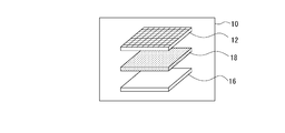
- each chip of the array sensor 12, the memory 16, and the calculation unit 18 is packaged as one package as illustrated in FIG. 7 in order to make the sensor unit 10 in terms of hardware tamper resistance.
- the chip as the memory 16 is laminated on the chip as the arithmetic unit 18, and the chip as the array sensor 12 is further laminated on the chip as the memory 16.
- the encryption unit that encrypts the read signal is formed in the chip as, for example, the array sensor 12.
- an encryption control unit 85 that generates an encryption key based on a photoelectric random number and causes the above-mentioned encryption unit to execute encryption based on the encryption key is included in a chip as a calculation unit 18.
- the electrical connection of each chip is made by Cu-Cu connection that connects Cu (copper) pads, and when the image sensor unit 10 is disassembled, these electrical connection parts are connected. Will be destroyed. In other words, as a result, tamper resistance is achieved in terms of hardware.
- FIG. 8 shows another example of the structure of the image pickup sensor unit 10, and the difference from FIG. 7 is that the vertical relationship between the calculation unit 18 and the memory 16 is interchanged.
- FIG. 9 shows yet another example of the structure of the image pickup sensor unit 10, and the difference from FIG. 7 is that a plurality of chips as the memory 16 are stacked (two layers in the example of the figure).
- the image sensor unit 10 may have a two-layer structure by forming the memory 16 on the same layer as the calculation unit 18, or the array sensor 12, the memory 16, and the calculation unit 18 may be on the same layer. It is also possible to have a one-layer structure formed in.
- the calculation unit 18 of this example starts the process shown in FIG. 10 at the time of activation and when an unauthorized access detection unit 86 detects an unauthorized access.
- acquisition of the photoelectric random number (S101) and generation of the encryption key (S105) are executed in response to the detection of unauthorized access. That is, the photoelectric random number is reacquired in response to the detection of unauthorized access, and the encryption key is regenerated based on the reacquired photoelectric random number.
- tamper resistance can be achieved in terms of software.
- the process shown in FIG. 10 can be started based on other conditions such as starting in response to an external instruction (for example, an instruction in response to an operation input) or starting at regular time intervals.
- the calculation unit 18 executes the still image imaging process in step S101.
- This still image imaging process is a process for capturing a still image that is the source of the generation of the encryption key, and the arithmetic unit 18 controls the array sensor 12 to capture an image for one frame (charge for each pixel). Read) is executed.
- the image data as a seed frame is saved in the memory 16.
- step S102 the calculation unit 18 executes the pixel value uniformity check process.
- This uniformity check process is a process of checking the uniformity of the brightness value for each pixel for the seed frame. Specifically, the calculation unit 18 is the number of pixels whose brightness value is zero or the saturation value (maximum value). To count.
- the pixel value uniformity check process can also be executed as a uniformity check process for the read signal value.
- step S103 the calculation unit 18 determines whether or not the uniformity is excessive. Specifically, it is determined whether or not the number of pixels counted in step S102 is equal to or greater than a predetermined threshold value (for example, a value corresponding to 30% to 50% of the number of effective pixels). When the number of pixels counted in step S102 is equal to or greater than the above threshold value and a determination result is obtained that the uniformity is excessive, the calculation unit 18 proceeds to step S104 to erase the seed frame, that is, in the memory 16. After executing the process of erasing the image data as the saved seed frame, the process returns to step S101.
- a predetermined threshold value for example, a value corresponding to 30% to 50% of the number of effective pixels.
- the seed frame can be re-imaged in response to the case where the randomness of the pixel value of the seed frame is low. That is, the photoelectric random number can be reacquired in response to the case where the randomness of the photoelectric random number is low. Therefore, it is possible to prevent encryption from being performed by an encryption key based on a random number having low randomness, and it is possible to improve security.
- step S103 when the determination result that the number of counted pixels is not equal to or more than the above threshold value and the uniformity is not excessive is obtained, the calculation unit 18 proceeds to step S105 to generate an encryption key.
- an encryption key representing a coefficient to be set for each amplifier in the amplitude control circuit 19 (or 19A) is generated based on the brightness value of each pixel in the seed frame.
- the encryption key is not generated based on the photoelectric random number in the form in which the luminance values for each pixel are directly assigned to the pixel positions where the luminance values are obtained.
- An encryption key is generated based on a photoelectric random number in a format in which at least a part of the brightness value for each pixel is assigned to a pixel position different from the pixel position from which the brightness value is obtained.
- step S106 the calculation unit 18 executes a process of erasing the seed frame, that is, a process of erasing the image data as the seed frame stored in the memory 16 by the imaging process of step S101.
- a process of erasing the seed frame that is, a process of erasing the image data as the seed frame stored in the memory 16 by the imaging process of step S101.
- the calculation unit 18 (encryption control unit 85) receives a photoelectric random number from, for example, the amplitude control circuit 19 (or 19A), and generates an encryption key in step S105 via the processes of steps S102 and S103.
- the erasing process of step S106 is unnecessary (of course, the erasing process of step S104 is also unnecessary).
- step S107 the calculation unit 18 erases the existing key if it exists.
- the encryption key is stored in the memory 16 by the process of step S108 performed in the past.
- the process of step S107 is a process of erasing the existing encryption key when the existing encryption key is stored in the memory 16 in this way. By performing such an erasing process of the existing key, it is possible to prevent the leakage of the encryption key used for encryption in the past, and prevent the signal encrypted in the past from being illegally decrypted. Can be planned.
- step S108 the arithmetic unit 18 executes the encryption key storage process. That is, the process of saving the encryption key generated in step S105 in the memory 16 is executed. In response to the execution of the saving process in step S108, the calculation unit 18 ends a series of processes shown in FIG.
- the image data (captured image data) obtained by imaging with the array sensor 12 is encrypted by using the encryption key saved in step S108.
- the arithmetic unit 18 (encryption control unit 85) transfers the coefficient for each pixel based on the stored encryption key to each amplifier in the amplitude control circuit 19 (or 19A) after the processing shown in FIG. 10 is completed. It is set so that the image signal obtained by the image pickup by the array sensor 12 is encrypted based on the stored encryption key.
- the array sensor 12 is supposed to capture a moving image, and encryption by the amplitude control circuit 19 (or 19A) is performed on each frame image constituting the moving image.
- the captured image data as a moving image encrypted as described above is stored in the memory unit 24 under the control of the control unit 23.
- the control unit 23 is capable of transmitting the captured image data stored in the memory unit 24 to the receiving device 3 via the communication unit 25 in this way.
- the image data is encrypted based on a photoelectric random number obtained in a frame period different from that of the image data to be encrypted.
- the difficulty of estimating the encryption key from the encrypted image is increased, and security can be improved.
- the receiving device 3 receives the captured image data encrypted with the encryption key (encryption filter) generated based on the photoelectric random number as described above from the imaging device 1, and decodes the received captured image data.
- the key used for decryption is the same key as the key used for encryption. That is, in this example, the common key cryptosystem is adopted. As is well known, in the common key cryptosystem, it is important to securely transfer the common key.
- the outline of the method is a method of passing a common key using public key cryptography.
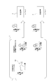
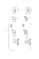
- the receiving device 3 creates a public key and a private key, and hands the public key to the imaging device 1 (FIG. 11A).
- the imaging device 1 that has acquired the public key uses the encryption key generated based on the photoelectric random number as the common key as described above, encrypts the common key with the public key, and transmits the encryption key to the receiving device 3 (FIG. 11B). Then, in the receiving device 3, the transmitted common key (decryption key) is decrypted using the private key created in FIG. 11A (FIG. 11C). As a result, in the receiving device 3, the encrypted image data received from the imaging device 1 can be decoded at high speed by using the common key decoded as described above.
- FIG. 11D schematically shows that image encryption is performed on the image pickup device 1 side using a common key
- FIG. 11E image data encrypted by the common key is used by the receiving device 3 on the common key. Decryption is schematically shown.
- the captured image data transmitted by the imaging device 1 to the receiving device 3 is the target data of the electronic signature.
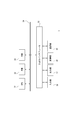
- the "sender side” in the figure corresponds to the imaging device 1
- the "receiver side” corresponds to the receiving device 3.
- the "electronic document” corresponds to the image data captured by the image pickup device 1 (in this example, it is encrypted based on a photoelectric random number).
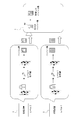
- the hash value of the electronic document is calculated, a private key as a signature generation key is generated, and the hash value is encrypted by the generated private key. Furthermore, the sender side generates a public key as a signature verification key based on the private key.
- the transmitted data includes a hash value encrypted by the private key as the electronic signature data. Further, the sender side includes the digital certificate data including the public key generated from the private key in the transmission data.
- the receiver side calculates the hash value of the electronic document received from the sender side. Further, on the receiver side, as a process indicating "signature verification" in the figure, the encrypted hash value in the digital signature data is decrypted by the public key included in the digital certificate. Then, the receiver side determines whether or not both hash values match. At this time, if the electronic document received on the receiver side has not been tampered with from the contents at the time of transmission, the two hash values will match. Therefore, it is possible to detect (determine) whether or not the electronic document has been tampered with by the above-mentioned match determination.
- the secret key as the signature generation key is generated based on the above-mentioned photoelectric random number, which makes it difficult to decipher the secret key.
- improve tampering detection performance when the tampering detection method using such an electronic signature is adopted, the secret key as the signature generation key is generated based on the above-mentioned photoelectric random number, which makes it difficult to decipher the secret key.
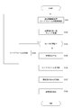
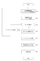
- the electronic signature encryption key generation process as the first embodiment will be described with reference to the flowchart of FIG.
- the process shown in FIG. 13 is executed by the control unit 23.
- the control unit 23 performs a process of acquiring a photoelectric random number in step ST1.
- the photoelectric random number it is conceivable to acquire a newly generated one in the imaging sensor unit 10.
- the photoelectric random number generated based on the electric signal value for each pixel is stored in the memory 16.
- the process of step ST1 can also be a process of acquiring the photoelectric random number stored in the memory 16 from the imaging sensor unit 10.
- the process of step ST1 when the process of acquiring the photoelectric random number newly generated in the image pickup sensor unit 10 is performed, in the process shown in FIG. 13, the unauthorized access detection unit 86 has detected the unauthorized access. Can be started according to. In this case, the electronic signature private key will also be updated based on the regenerated photoelectric random number when an unauthorized access from the outside is detected.
- the process shown in FIG. 13 can be started based on other conditions such as starting at regular time intervals.
- the control unit 23 when the imaging sensor unit 10 newly generates a photoelectric random number for secret key generation, the control unit 23 generates the image data (seed frame) that is the source of the photoelectric random number after the generation of the new photoelectric random number. ) Can be instructed to the imaging sensor unit 10.
- step ST2 the control unit 23 generates a secret key based on the photoelectric random number.
- a method of generating a secret key from a photoelectric random number for example, a method of RSA encryption (RSA: Rivest Shamir Adleman) can be mentioned, but the method is not limited to a specific method.
- step ST3 the control unit 23 generates a public key based on the private key. That is, the public key as the signature verification key is generated based on the private key as the signature generation key.
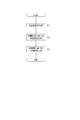
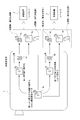
- the flowchart of FIG. 14 shows an example of a processing procedure to be executed in order to detect falsification of captured image data based on the private key and public key generated as described above.
- the control unit 23 executes the process shown as the image pickup device 1
- the CPU 31 executes the process shown as the receiving device 3.
- the CPU 31 makes a transmission request for encrypted image data to the imaging device 1 side in step S301.
- the control unit 23 waits for the above transmission request in step S201, and when there is a transmission request, proceeds to step S202 to calculate the hash value of the requested image data. That is, the hash value of the captured image data stored in the memory unit 24 and requested by the transmission request is calculated.
- the hash function used for the calculation of the hash value the same hash function used by the receiving device 3 side in the hash value calculation in step S304, which will be described later, is used.
- the hash function include, for example, SHA-1 and SHA-2, but the hash function is not limited to a specific hash function.
- step S203 the control unit 23 encrypts the hash value with the private key. That is, the hash value calculated in step S202 is encrypted by the secret key generated based on the photoelectric random number in the process of FIG. Further, in the following step S204, the control unit 23 transmits the requested encrypted image data, the encrypted hash value, and the public key to the requesting receiving device 3. That is, the captured image data in the encrypted state requested to be transmitted, the hash value encrypted in step S203, and the public key generated in the process of FIG. 13 are transmitted to the receiving device 3 of the transmission request source.
- the CPU 31 waits for the reception of the data transmitted in step S204 in step S302, and when the data is received, first decodes the encrypted image data in step S303. That is, the captured image data in a state encrypted by the encryption key (encryption filter) based on the photoelectric random number is decrypted by the same encryption key (decryption key) acquired in advance from the imaging device 1.
- the encryption key as the encryption filter is securely acquired by the receiving device 3 from the imaging device 1 in advance by the method illustrated in FIG.
- the CPU 31 calculates the hash value of the captured image data decoded in step S303 as a process of calculating the hash value.
- step S305 the CPU 31 decrypts the encryption hash value with the public key. That is, the encrypted hash value received from the image pickup device 1 side is decrypted by the public key also received from the image pickup device 1 side. Then, in step S306, the CPU 31 performs a match determination between the two hash values, that is, a match determination between the hash value calculated in step S304 and the hash value decoded in step S305. By this matching determination, it is determined whether or not the captured image data has been tampered with.
- Second Embodiment> [2-1. Image encryption method of the second embodiment] Subsequently, the second embodiment will be described. Also in the second embodiment, the configurations of the imaging device 1 and the receiving device 3 are the same as those described in the first embodiment, and therefore duplicate explanations are avoided. In the following description, parts that are similar to the parts that have already been explained are designated by the same reference numerals and the description thereof will be omitted.
- encryption is performed for the target area in the image data. Specifically, in the second embodiment, the entire image and the target area are encrypted based on different encryption keys, and the target area is encrypted based on different encryption keys in the specific part area and the other areas. By performing the conversion, the confidentiality level of the information is gradually changed depending on the decryption key held on the receiver side of the image.
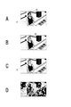
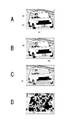
- FIG. 15 and 16 are diagrams for explaining an image of stepwise image encryption in the second embodiment.
- FIG. 15 shows an image of stepwise image encryption when the target class is a person.
- FIG. 15A shows an image before encryption.
- the target area AT is the entire area where the person is projected in the image.
- the specific area AS which is the area of the specific part, is the area of the face of the person.
- FIG. 15B shows an image in which only the specific area AS is encrypted
- FIG. 15C shows an image in which only the target area AT including the specific area AS is encrypted
- FIG. 15D shows an image in which the entire image is encrypted.
- FIG. 16 shows an image of stepwise encryption when the target class is a vehicle
- FIG. 16A shows an image before encryption
- the target area AT is the entire area where the vehicle is projected in the image
- the specific area AS is the area of the passenger of the vehicle and the license plate.
- FIG. 16B is an image in which only the specific area AS is encrypted
- FIG. 16C is an image in which only the target area AT including the specific area AS is encrypted
- FIG. 16D is an image in which the entire image is encrypted.
- the encryption keys include only the first encryption key corresponding to the encryption of the entire image, the second encryption key corresponding to the encryption of only the target area AT, and the specific area AS. At least three types of third encryption keys corresponding to the above encryption are generated.
- FIG. 17 is a diagram for explaining an example of a specific method of stepwise encryption.
- the target image is not individually encrypted based on the first, second, and third encryption keys, but the target image is encrypted based on a synthetic key that combines these multiple encryption keys. To make it.
- a third encryption key for encrypting the specific area AT, a second encryption key for encrypting the entire target area AT, and a first encryption key for encrypting the entire image are prepared.
- three types of photoelectric random numbers may be obtained (that is, three types of seed frames are imaged), but in this example, the time required for encryption key generation is shortened. Therefore, three types of encryption keys are generated from a common photoelectric random number.
- the three types of random numbers hereinafter, the first random number and the second random number, respectively
- the arrangement of the numerical values for each pixel in the common photoelectric random number is different are different.
- Random numbers expressed as third random numbers
- the third encryption key is generated as an encryption key obtained by extracting the numerical value of each pixel of the specific area AS from the numerical value of the third random number.
- the second encryption key is generated as an encryption key obtained by extracting the numerical value of each pixel of the target area AT from the numerical value of the second random number.
- the first encryption key is generated as an encryption key to which the first random number is applied as it is.
- FIG. 18 is an explanatory diagram of an example of a change in the confidentiality level.
- level 0 has no key
- level 1 holds only the first encryption key
- level 2 holds the composite key of the first and second encryption keys
- level 3 holds the first, second, and third encryption keys. It means holding the synthetic key of.
- the encrypted image cannot be decrypted on the receiver side of the image, and an image in which the entire area is encrypted can be obtained.
- the receiver side of the image can decrypt the area other than the target area AT by using the first encryption key, and therefore an image in which only the target area AT is encrypted can be obtained.
- the receiver side of the image can decrypt the area other than the specific area AS by using the synthetic key of the first and second encryption keys, and the image in which only the specific area AS in the target is encrypted can be obtained. can get.
- the receiver side of the image can decrypt the entire image using the composite key of the first, second, and third encryption keys, and in this case, an image without confidential information is obtained. Can be done.
- the image to be encrypted is a moving image
- the target object projected in the image may be displaced in the image with the passage of time. Therefore, when performing encryption for the target area AT as described above, it is necessary to track the target.
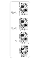
- FIG. 19 the target class is assumed to be "person". Further, in FIG. 19, for convenience of explanation, an example is given in which the specific area AC and the other areas are not distinguished in the target area AT, and only the target area AT and the other areas in the image are encrypted separately.
- the frame F1 shown in FIG. 19A shows a state in which a person in the target class has not yet framed in.
- a person in the target class has not yet framed in.
- an object as a "tree" that is not a target class is identified in the image.
- encryption for the entire image is performed regardless of the presence or absence of a target. That is, in this example, the image of each frame F is encrypted by the amplitude control circuit 19 (or 19A) based on the first encryption key corresponding to the entire image, and then stored in the memory 16.
- the white key marks shown in each sub-figure of FIG. 19 indicate that the entire image is encrypted as the output image.
- the calculation unit 18 For tracking the target, the calculation unit 18 detects the area of the object in the image and class-identifies it (processing of the object area recognition unit 82 and the class identification unit 83 described above). In order to perform these processes, the calculation unit 18 decodes the frame image encrypted and stored as described above. That is, the calculation unit 18 executes the process for target tracking while decrypting the frame image encrypted based on the first encryption key. The arithmetic unit 18 performs decoding at this time by an on-the-fly method. As a result, it is possible to reduce the possibility that the plaintext image signal is leaked when tracking the target, and it is possible to improve security.
- the frame F2 shown in FIG. 19B shows a state in which the target class “person” is framed in. In this state, the target class "person” is identified along with the already identified "tree".
- the calculation unit 18 calculates the bounding box 40 with accurate position coordinates surrounding the area of the object.
- FIG. 19C shows an example of a bounding box 40 for an image of a person who is a target class. That is, the bounding box 40 is calculated as a more accurate region of the object corresponding to the target class. Further, the calculation unit 18 (object area recognition unit 82) calculates the ROI 41 which is the region of interest based on the bounding box 40.
- FIG. 19D shows the ROI 41 and the bounding box 40.
- the ROI 41 is calculated by, for example, expanding the vertical and horizontal size (xxy) of the bounding box 40 (axxby).
- the enlargement scales a and b can be set separately in the vertical and horizontal directions, and the enlargement ratio may be fixed, but it is also conceivable to specify the enlargement scale from the outside of the image sensor unit 10 (for example, the image processor 21).
- this ROI41 is set as the target area AT, and encryption is performed using an encryption key different from the entire image.
- the frame F2 is a frame in which the target class is newly identified in the image, and can be paraphrased as a target class discovery frame.
- the ROI 41 cannot be encrypted based on the second encryption key for the target class discovery frame.
- the target class discovery frame has already been encrypted based only on the first encryption key and stored in the memory 16. If the target class discovery frame encrypted based only on the first encryption key is output as it is, the image area of ROI41 is disclosed to the holder of only the first encryption key without concealment. Will end up.
- the target class discovery frame is erased from the memory 16 so that an appropriate information concealment level according to the decryption key held by the image receiver is realized.
- FIG. 19E represents frame F3, which is the next frame after frame F2. From the frame F next to the target class discovery frame, encryption based on the second encryption key for ROI41 is performed.
- the ROI 41 here is the ROI 41 calculated at the time of the frame F2 which is the target class discovery frame.
- the ROI 41 is set to a larger range than the bounding box 40.
- a person as a target class fits in ROI41. That is, the person as the target class falls within the target range of encryption based on the second encryption key.
- the bounding box 40 and the ROI 41 for the target class are calculated so that the target class is tracked (see FIG. 19F).
- the ROI41 calculated in the previous frame F is encrypted based on the second encryption key (see FIG. 19G).
- FIG. 19H shows the frame Fn after the "person" as the target class is framed out. ROI41 is no longer calculated because the target class is out of frame. Therefore, the image of the frame Fn is encrypted based only on the first encryption key.
- ROI 41 is not limited to the rectangular area.
- ROI 41 may be calculated from the area of an object of that target class using, for example, semantic segmentation, ie object area detection at the pixel level.
- FIG. 20 shows ROI 41 based on semantic segmentation.
- a non-rectangular ROI 41 is set by expanding the pixel area as an object (for example, a person).
- the rectangular ROI 41 may not include a part or may be too large. If a non-rectangular ROI 41 is generated according to the object position at the pixel level, it is possible to appropriately set the concealed area related to the target without excess or deficiency.
- FIG. 21 shows a process corresponding to the process from imaging the seed frame to storing the random number that is the source of the encryption key.
- the same step numbers are assigned to the processes that are the same as the processes already described in FIG. 10, and the description thereof will be omitted.
- the process of FIG. 21 is started at the time of activation and when an unauthorized access is detected by the unauthorized access detection unit 86. Alternatively, it can be started based on other conditions such as starting at regular intervals. It should be noted that at least a part of the processes described with reference to FIGS. 21 and 22 can be realized as processing by hardware.
- step S151 when the calculation unit 18 in this case determines that the uniformity is excessive in step S103, the calculation unit 18 proceeds to step S151 to generate random numbers at each level.
- the specific region AS is not distinguished in the target region AT, two types of random numbers, the first random number and the second random number described above, are generated. Since the method of generating various random numbers based on the photoelectric random numbers of the seed frame has already been described, duplicate explanations will be avoided.
- the calculation unit 18 executes the seed frame erasing process in step S106 in response to executing the random number generation process in step S151. Then, in response to executing the erasing process in step S106, the calculation unit 18 executes a process of erasing any existing random numbers in step S152. That is, if there are random numbers (first random number and second random number) of each level stored in the memory 16 in the process of step S153 executed in the past, these random numbers are deleted. In step S153 following step S152, the calculation unit 18 performs a process of storing the random numbers of each level generated in step S151 in the memory 16, and ends a series of processes shown in FIG.
- FIG. 22 shows a process for encrypting the target image based on the generated encryption key.
- the calculation unit 18 waits for the start of imaging of the image to be encrypted in step S401, and when the imaging starts, the encryption process using the first encryption key is executed in step S402. That is, the amplitude control circuit 19 (or 19A) is instructed to specify the coefficient for each pixel based on the first encryption key to execute the encryption of the read signal of the array sensor 12.
- the first encryption key is an encryption key to which the first random number is applied as it is.
- step S403 the calculation unit 18 executes the object area recognition process, and further executes the class identification process in step S404.
- the object area recognition process in step S403 is the process of the object area recognition unit 82 described above, and detects a candidate object from the image of the current frame and recognizes the object area.
- the class identification process in step S404 is the process of the class identification unit 83 described above, and class identification is performed on the object detected by the object area recognition process described above.
- class identification is performed for each and classified into each class. For example, in the case of FIG. 19B above, class identification and classification are performed such that one object of the class "tree" and one object of the class "person".
- the calculation unit 18 executes the processes of steps S403 and S404 while decrypting the frame image encrypted in step S402 and step S413 described later by an on-the-fly method.
- step S405 the calculation unit 18 determines whether or not the target class exists. That is, it is determined whether or not the target class exists among the classes identified in step S404. If the target class does not exist, the calculation unit 18 waits for the next frame in step S406 (waits for the arrival of the next frame period), and then returns to step S402. That is, until the target class is detected, the encryption process for the entire image in step S402, the object area recognition process in step S403, and the class identification process in step S404 are repeatedly executed frame by frame.
- step S405 If it is determined in step S405 that the target class exists, the calculation unit 18 proceeds to step S407 to calculate the bounding box 40, and then in step S408, the ROI 41 is calculated. Further, in the following step S409, the arithmetic unit 18 generates a synthetic key in which the second encryption key to which the numerical value of the second random number is applied only to the ROI 41 and the first encryption key are combined.
- the calculation unit 18 determines in step S410 whether or not it is the target class discovery frame. If the current frame is a target class discovery frame, the calculation unit 18 executes a process of deleting the target class discovery frame in step S411. As a result, it is possible to prevent the target image portion of the target class discovery frame from being hidden even though the key holding level is level 1.
- step S410 if the current frame is not the target class discovery frame, the calculation unit 18 passes the erasing process of step S411 and waits for the next frame in step S412. Further, even when the erasing process of step S411 is executed, the calculation unit 18 also performs a process of waiting for the next frame in step S412.
- the calculation unit 18 executes the encryption process using the synthetic key generated in the previous frame in step S413. That is, the amplitude control circuit 19 (or 19A) is instructed to instruct the coefficient for each pixel based on the synthetic key to execute the encryption of the read signal of the array sensor 12.
- step S414 following step S413, the calculation unit 18 determines whether or not the imaging is completed, that is, whether or not the imaging of the image to be encrypted should be completed, for example, when an external imaging end instruction is given. judge. If the imaging is not completed, the calculation unit 18 returns to step S403. As a result, the processes described so far are repeated until the imaging is completed. That is, if the target class continues to exist, the ROI41 for the target class is calculated, the synthetic key is generated based on the calculated ROI41, and the encryption process is performed based on the synthetic key generated in the previous frame. If the target class no longer exists, the encryption process using the synthetic key is not performed, and the encryption process using the first encryption key is executed.
- the calculation unit 18 ends a series of processes shown in FIG.
- the ROI 41 is set as an area in which the bounding box 40 is expanded so that an object as a target can be included in the next frame, but the vertical and horizontal sizes (xxy) are expanded (ax ⁇ by). ),
- the scales a and b of the enlargement may be set according to the frame rate. For example, if the frame rate is low, the frame interval time becomes long and the amount of movement of an object such as a person becomes large. Therefore, it is conceivable to make the ROI 41 wider than when the frame rate is high.
- the bounding box 40 and the ROI 41 are calculated and calculated by the same method as the method described above for the specific part.
- a third encryption key is generated by applying the numerical value of the third random number to the ROI 41. Then, a synthetic key obtained by synthesizing the first, second, and third encryption keys may be generated and used for encrypting the image of the next frame.
- level 1 is a level at which an image in which only the entire target area AT is encrypted can be obtained
- level 2 is a specific level in the target area AT. Only the area AS is the level at which an encrypted image can be obtained.
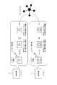
- FIG. 23 schematically shows a process performed by the imaging device 1 when transmitting an image to the receiving device 3.
- the captured image data to be transmitted is image data encrypted by a composite key of the first, second, and third encryption keys.
- the captured image data encrypted with the synthetic key will be referred to as “encrypted image data Gc”.
- the image pickup device 1 has a hash value of image data obtained by decrypting the encrypted image data Gc with the first encryption key as a hash value to be transmitted to the level 1 receiving device 3 (hereinafter referred to as “hash value H1”). ) Is calculated.
- the hash value H1 calculated in this way is encrypted with a private key as a signature generation key (generated based on a photoelectric random number as in the first embodiment), and A public key as a signature verification key generated based on the private key is transmitted together with the encrypted image data Gc.
- the image pickup device 1 has a hash value of the image data obtained by decoding the encrypted image data Gc with the synthetic keys of the first and second encryption keys as the hash value to be transmitted to the level 2 receiving device 3 (hereinafter referred to as the hash value). (Indicated as "hash value H2") is calculated. Then, for the level 2 receiving device 3, the hash value H2 calculated in this way is encrypted with the private key as the signature generation key, and the public key as the signature verification key is encrypted image data Gc. Send with.
- FIG. 24 schematically shows the processing on the receiving device 3 side.
- the encrypted image data Gc received from the imaging device 1 is decrypted by the first encryption key owned by the user, and the hash value (hereinafter, “hash value H1a”) of the decrypted image data is obtained. Is written as).
- the level 1 receiving device 3 decrypts the hash value H1 received from the imaging device 1 and encrypted by the private key with the public key. The value obtained by this decoding is referred to as a hash value H1b.
- the level 1 receiving device 3 determines a match between the hash value H1a and the hash value H1b.
- the encrypted image data Gc received from the imaging device 1 is decrypted by the synthetic key of the first and second encryption keys owned by the receiver 1, and the hash value of the decrypted image data (hereinafter referred to as “hash value”). (Indicated as “hash value H2a”) is calculated. Further, the level 2 receiving device 3 decrypts the hash value H2 received from the imaging device 1 encrypted by the private key with the public key. Assuming that the value obtained by this decoding is the hash value H2b, the level 2 receiving device 3 determines that the hash value H2a and the hash value H2b match.
- the hash value is generally generated at the time of recording the target data for tampering detection.
- hash values H1 and H2 in the above example
- the hash value of each level is generated at the time of transmitting the encrypted image data Gc in response to the transmission request from the receiving device 3.
- the hash value needs to be generated only for the key level of the receiving device 3 that made the transmission request when the transmission request is made, and the hash value of each level is generated once when the captured image data is recorded. There is no need to generate it. Therefore, it is possible to suppress the processing delay associated with the generation of the hash value.
- the control unit 23 waits for a transmission request from the receiving device 3 side in step S501. That is, it waits for the transmission request of the encrypted image data Gc.
- the control unit 23 acquires the level information of the receiving device 3. That is, the information representing the level of the decryption key held by the receiving device 3 that made the transmission request is acquired. In this example, it is assumed that the receiving device 3 transmits the information at the level to the imaging device 1 together with the transmission request.
- step S503 the control unit 23 decodes the encrypted image data Gc at a decoding level corresponding to the level of the receiving device 3. That is, the encrypted image data Gc stored in the memory unit 24 is decrypted by the decryption key corresponding to the level information acquired in step S402. Specifically, if it is level 1, it is decrypted by the first encryption key, if it is level 2, it is decrypted by the synthetic key of the first and second encryption keys, and so on. Decryption is performed with the decryption key according to the possession level of.
- step S504 following step S503, the control unit 23 calculates the hash value of the decrypted image data, and in step S505 that follows, encrypts the hash value with the private key. Further, in the following step S506, the control unit 23 transmits the encrypted image data Gc, the encrypted hash value, and the public key to the requesting receiving device 3, and ends the series of processes shown in FIG. 25.
- the public key transmitted in step S506 is a public key as a signature verification key generated based on the private key as the signature generation key generated based on the photoelectric random number.
- a common key is used at each level for the public key and its paired private key, but these public keys and private keys may use different keys for each level.
- the receiving device 3 at each level holds the private key and the public key, and transmits the public key held by each to the imaging device 1.
- the image pickup apparatus 1 generates a hash value Hd obtained by hashing the photoelectric random number.
- the imaging device 1 encrypts the photoelectric random number with the public key of the corresponding level for each level of the receiving device 3.
- the photoelectric random number encrypted by the level 1 public key is transmitted to the level 1 receiving device 3
- the photoelectric random number encrypted by the level 2 public key is transmitted to the level 2 receiving device 3. Send.
- the receiving device 3 side of each level decrypts the photoelectric random number encrypted with the public key by the private key of the level owned by itself. Then, the receiving device 3 at each level calculates a hash value from the decoded photoelectric random number and transmits it to the imaging device 1, respectively.
- the imaging device 1 determines that the hash value received from the receiving device 3 at each level matches the original hash value Hd calculated in FIG. 27. When the received hash value matches the hash value Hd, the imaging device 1 registers the receiving device 3 that has transmitted the hash value as an official receiver.
- the image pickup apparatus 1 encrypts the electronic signature public key for level 1 and the electronic signature public key for level 2 that it owns with the public keys of the respective levels.
- the public key of each level used for this encryption is a public key transmitted by the receiving device 3 of each level and held by the imaging device 1 as described with reference to FIG. 26 above.
- the imaging device 1 transmits a level 1 electronic signature public key encrypted with the level 1 public key to the level 1 receiving device 3, and uses the level 2 public key to the level 2 receiving device 3. Send the encrypted level 2 digital signature public key.
- the receiving device 3 at each level decrypts the encrypted electronic signature public key received from the imaging device 1 with the private key at its own level.
- the receiving device 3 at each level refers to the electronic signature public key associated with and managed by the imaging device 1 from a predetermined server device such as a certificate authority server on the network, and refers to the referred electronic device. Match determination is performed between the signature public key and the digital signature public key decrypted as described above. When the electronic signature public keys of both levels match, the receiving device 3 at each level registers the image pickup device 1 as an appropriate sender.
- the information of the owner of the electronic signature public key is managed on the network as public information and can be confirmed.
- the system for this confirmation is not particularly limited, and examples thereof include a PGP (Pretty Good Privacy) system and a PKI (Public Key Infrastructure) system.
- the third embodiment generates a private key for electronic signature in a blockchain system based on a photoelectric random number.
- the blockchain means a block containing a plurality of transaction data connected in chronological order.
- the blockchain system is a system that handles such a blockchain, and means a system that distributes and manages transaction data (transactions) using a P2P (Peer to Peer) network.
- P2P Peer to Peer
- FIG. 31 is a block diagram illustrating the hardware configuration of the blockchain system.
- each of a plurality of user terminals 50 is connected to, for example, a network 2 as the Internet, and each user terminal 50 can perform data communication with each other via the network 2. It is said that.
- FIG. 32 is a block diagram showing an example of the internal configuration of the user terminal 50.
- the user terminal 50 has the same configuration as the receiving device 3 shown in FIG. 3, and the camera unit 51 is connected to the input / output interface 35.
- the camera unit 51 has at least the array sensor 12 shown in FIG. 2, and is configured to be capable of generating the image data as the seed frame described above.
- the user terminal 50 connected to the network 2 generates a private key for digital signature.
- a public key is generated from this private key, and a blockchain address is generated based on the public key.
- the blockchain address is information corresponding to an account number when compared to a bank account, and the transaction of virtual currency in the blockchain system is performed by exchanging currency between the blockchain addresses.
- the public key generated from the private key in the blockchain system is encrypted by the private key and used for tampering detection of the transaction broadcast to the P2P network. That is, the private key or public key in this case is used to check whether or not the transaction has been performed properly.
- a secret key for electronic signature in the blockchain system is generated based on a photoelectric random number.
- the CPU 31 in the user terminal 50 causes the camera unit 51 to generate image data as a seed frame when generating a private key for electronic signature. Then, the electric signal value of each pixel of the image data is acquired as a photoelectric random number, and the secret key is generated based on the photoelectric random number. This makes it possible to make it more difficult to decipher the private key for digital signature in the blockchain system than when using a pseudo-random number.
- SC system smart contract system
- contract a transaction contract
- the SC system is pre-programmed so that the contract details are automatically executed when specific conditions are met, which enables trustless transactions.
- trustless transactions mean that digital transactions are conducted only between the parties without the need for mediation by a third party.
- FIG. 33 is a diagram conceptually showing the configuration of the SC system.
- various user terminals 50 exist on the blockchain system.
- the smart contract application in the figure represents a set of user terminals 50 that enjoy smart contract services and user terminals 50 that manage the operation of smart contracts.
- the verifier group in the figure represents a set of user terminals 50 as contract verification workers.
- the verification workers of the smart contract are divided into a plurality of groups (verifier groups), and the verification workers may synchronize data with each other in each group.
- the user terminal 50 as the elector in the smart contract application selects the verifier group based on the photoelectric random number.
- a leader of a verification worker (verifier leader in the figure) may be selected within the group, and in that case, the user terminal 50 as the selected person selects the leader based on a photoelectric random number.
- the selection of the verifier group as described above can be rephrased as the selection of a plurality of verification workers.
- the electric signal value of each pixel of the image data as the seed frame generated by the CPU 31 in the camera unit 51 is used as a photoelectric random number. It is acquired and performed based on the photoelectric random number.
- DAPPs is an application using blockchain technology.
- the CPU 31 acquires the electric signal value of each pixel of the image data as the seed frame generated by the camera unit 51 as a photoelectric random number.
- the representative is selected based on the photoelectric random number.
- the photoelectric random number one in which the pixel positions are shuffled as described with reference to FIG. 4 can be used. Further, also in the third embodiment, the image data that is the source of the photoelectric random number can be erased from the memory, and the photoelectric random number is regenerated in response to the detection of unauthorized access from the outside. You can also. In the third embodiment, for example, the CPU 31 is instructed to erase or regenerate the photoelectric random number.
- Modification example> The embodiment is not limited to the specific examples described so far, and various modified examples can be considered.
- the case where the target data of the electronic signature is the image data is illustrated, but the present technology detects tampering using the electronic signature for various data such as text data and voice data. Can be widely and preferably applied when performing the above.
- the generation of the secret key based on the photoelectric random number is performed outside the imaging sensor unit 10, but the generation of the secret key based on the photoelectric random number is performed inside the imaging sensor unit 10 (for example, calculation). It can also be generated in part 18).
- the following method as a modified example can be adopted.
- One is to apply the dark current noise and readout noise, which are reduced by ordinary image sensors, to the generation of high randomness.
- a method of increasing dark current noise due to thermal noise by reducing the exposure time (accumulation time) and increasing the amplification factor of the amplifier at the time of capturing a seed frame of random numbers can be mentioned.
- a method of using the captured image obtained as a result of reading with the circuit for reducing read noise eg, a circuit for noise reduction such as an adaptive gain type amplifier turned off can be mentioned as a seed frame.
- random numbers are obtained by referring to only the pixels of one of the color filters (filters in one wavelength band). It can also be used as a seed frame for generation. For example, in the case of a Bayer array, only the red pixels are referred to.
- the random number used for encrypting the target data is not limited to the photoelectric random number.
- pseudo-random numbers can be used.
- a true random number a method of detecting a natural phenomenon that is practically impossible to predict or reproduce, such as a change in heat or sound, with a corresponding sensor and generating a random number based on that value. Can be mentioned.
- the encryption key generation device (imaging device 1 or user terminal 50) of the embodiment is an array sensor (12) in which a plurality of pixels having visible light or non-visible light light receiving elements are arranged one-dimensionally or two-dimensionally. ) Is provided with a key generation unit (control unit 23 or CPU 31: see step ST2) that generates a secret key for electronic signature based on a photoelectric random number obtained based on the photoelectric conversion. This makes it possible to make it more difficult to decipher the private key for digital signature than when using a pseudo-random number. Therefore, the tampering detection performance can be improved.
- the key generation unit generates a private key for electronic signature of image data.
- the key generation unit generates a private key for electronic signature of image data.
- the key generation unit generates a secret key for electronic signature of the image data obtained by imaging with the array sensor.
- the array sensor for obtaining image data is shared with the array sensor for obtaining photoelectric random numbers. Therefore, it is not necessary to provide an array sensor for generating photoelectric random numbers separately from the array sensor that generates image data, and it is possible to reduce the number of parts and the cost.
- the encryption unit (amplitude control circuit 19 or 19A, the calculation unit 18) that encrypts the image data obtained by imaging with the array sensor and the encryption unit are used. It includes a transmission processing unit (control unit 23: see steps S204 and S506) that performs a process of transmitting encrypted image data to an external device. This makes it possible to securely transmit the image data as the target data of the electronic signature. Therefore, it is possible to improve security in terms of preventing leakage of image contents.
- the encryption unit encrypts the image data with the encryption key generated based on the photoelectric random number. As a result, it is possible to make it more difficult to decrypt the encryption key than when using a pseudo-random number for encrypting the image data. Therefore, the security can be further improved.
- the encryption unit encrypts the image data so that the decipherable image range differs depending on the level of the decryption key used for decrypting the image data
- the transmission processing unit uses the transmission processing unit.
- the image data encrypted with the decryption key of the same level as the decryption key of the external device is decrypted and decrypted.
- the hash value of the image data is generated, and the hash value encrypted by the private key and the encrypted image data are transmitted to an external device (see FIGS. 23 and 25).
- the hash value is generated when the transmission request is made. It is only necessary to perform the decryption key level of the receiving device in which the above is performed, and it is not necessary to generate the hash value of each level at once when recording the image data (captured image data). Therefore, it is possible to suppress the processing delay associated with the generation of the hash value.
- the key generation unit (CPU 31) generates a secret key for electronic signature in the blockchain system based on the photoelectric random number. This makes it possible to make it more difficult to decipher the private key for digital signature in the blockchain system than when using a pseudo-random number. Therefore, it is possible to improve the falsification detection performance of the target data of the electronic signature in the blockchain system.
- the encryption key generation device as an embodiment includes a verifier selection unit (CPU 31: see FIG. 33) that selects a contract verification worker in a smart contract system based on a photoelectric random number. This makes it possible to make the random numbers used for selecting the contract verification worker more difficult to decipher than when using pseudo-random numbers. Therefore, the fairness of the selection of contract verification workers can be enhanced.
- a verifier selection unit CPU 31: see FIG. 33
- the encryption key generation device as an embodiment includes a representative selection unit (CPU 31) that selects a representative from the users of the service by DAPPs based on the photoelectric random number. This makes it possible to make it more difficult to decipher the random numbers used for selecting representatives from the DApps service recipients than when using pseudo-random numbers. Therefore, the fairness of the selection of representatives from DApps service recipients can be enhanced.
- a representative selection unit CPU 31
- the key generation unit acquires the value of the electric signal for each pixel obtained by the photoelectric conversion as a photoelectric random number to generate a secret key. This makes it possible to generate an electronically signed private key that is difficult to decipher. Therefore, the tampering detection performance can be improved.
- the key generation unit allocates at least a part of the electric signal values for each pixel to a pixel position different from the pixel position from which the electric signal value is obtained.
- the private key is generated based on the photoelectric random number in the above format. As a result, it is difficult to decipher the electronic signature private key as compared with the case of using a photoelectric random number in which the value of the electric signal for each pixel is directly assigned to the pixel position where the value of the electric signal is obtained. Therefore, the tampering detection performance can be improved.
- the erasing processing unit (calculation unit 18 or control unit 23) that performs processing for erasing the image data that is the source of the photoelectric random number from the memory.
- the CPU 31 see steps S106, ST1, etc.).
- the regeneration processing unit (calculation unit 18) that performs processing for regenerating the photoelectric random number in response to the detection of unauthorized access from the outside of the encryption key generation device.
- the control unit 23 or the CPU 31 see FIG. 10, step ST1 and the like.
- the information processing apparatus uses a random number obtained based on photoelectric conversion by an array sensor in which a plurality of pixels having visible or invisible light receiving elements are arranged one-dimensionally or two-dimensionally.
- This is an encryption key generation method for generating a private key for a digital signature based on a certain photoelectric random number.
- the present technology can also adopt the following configurations.
- An encryption key generator equipped with a generator.
- the key generator The encryption key generation device according to (2) above, which generates a private key for an electronic signature of image data obtained by imaging with the array sensor.
- the encryption unit The encryption key generation device according to (4) above, which encrypts the image data with an encryption key generated based on the photoelectric random number.
- the encryption unit The image data is encrypted so that the decodable image range differs depending on the level of the decryption key used for decoding the image data.
- the transmission processing unit The image data encrypted by a decryption key at the same level as the decryption key possessed by the external device in response to a request for transmission of the image data encrypted by the encryption unit by the external device.
- the hash value of the decrypted image data is generated, and the hash value encrypted by the private key and the encrypted image data are transmitted to the external device (4) or (5). ).
- the encryption key generator. (7) The key generator The encryption key generation device according to (1) above, which generates a private key for an electronic signature in a blockchain system based on the photoelectric random number.
- the encryption key generation device according to (7) above comprising a verifier selection unit that selects a contract verification worker in a smart contract system based on the photoelectric random number.
- the encryption key generation device comprising a representative selection unit that selects a representative from the users of the service by DApps based on the photoelectric random number.
- the key generator The encryption key generation device according to any one of (1) to (9) above, wherein the value of the electric signal for each pixel obtained by the photoelectric conversion is acquired as the photoelectric random number to generate the secret key.
- the key generator The secret key is generated based on the photoelectric random number in a format in which at least a part of the electric signal value for each pixel is assigned to a pixel position different from the pixel position from which the electric signal value is obtained.
- the encryption key generator according to 10).
- the encryption key according to any one of (1) to (11) above, which includes an erasing processing unit that performs processing for erasing the image data that is the source of the photoelectric random number from the memory after the photoelectric random number is generated.
- Generator (13) The above-described (1) to (12), wherein the encryption key generator is provided with a regeneration processing unit that performs a process for regenerating the photoelectric random number in response to the detection of unauthorized access from the outside.
- Cryptographic key generator is provided with a regeneration processing unit that performs a process for regenerating the photoelectric random number in response to the detection of unauthorized access from the outside.
Landscapes
- Engineering & Computer Science (AREA)
- Computer Security & Cryptography (AREA)
- Signal Processing (AREA)
- Theoretical Computer Science (AREA)
- Computer Networks & Wireless Communication (AREA)
- General Physics & Mathematics (AREA)
- Physics & Mathematics (AREA)
- General Engineering & Computer Science (AREA)
- Computer Hardware Design (AREA)
- Software Systems (AREA)
- General Health & Medical Sciences (AREA)
- Bioethics (AREA)
- Health & Medical Sciences (AREA)
- Computational Mathematics (AREA)
- Multimedia (AREA)
- Mathematical Analysis (AREA)
- Mathematical Optimization (AREA)
- Pure & Applied Mathematics (AREA)
- Power Engineering (AREA)
- Studio Devices (AREA)
- Lock And Its Accessories (AREA)
- Mobile Radio Communication Systems (AREA)
Abstract
Description
これにより、電子署名用の秘密鍵について、疑似乱数を用いる場合よりも解読を困難化することが可能とされる。
これにより、電子署名の対象データが画像データとされる場合に対応して、電子署名用の秘密鍵について、疑似乱数を用いる場合よりも解読を困難化することが可能とされる。
これにより、画像データを得るためのアレイセンサが、光電乱数を得るためのアレイセンサと共通化される。
これにより、電子署名の対象データとしての画像データをセキュアに送信することが可能とされる。
これにより、画像データの暗号化についても、疑似乱数を用いる場合より暗号鍵の解読を困難化することが可能とされる。
これにより、画像データの受信装置に対して該受信装置が有する復号鍵のレベルに応じたハッシュ値を送信すべき場合において、ハッシュ値の生成は、送信要求が行われた際に、該送信要求を行った受信装置の復号鍵のレベルについてのみ行えば済み、画像データ(撮像画像データ)の記録時に各レベルのハッシュ値を一度に生成する必要がなくなる。
これにより、ブロックチェーンシステムにおける電子署名用の秘密鍵について、疑似乱数を用いる場合より解読を困難化することが可能とされる。
これにより、コントラクト検証作業者の選出に用いる乱数について、疑似乱数を用いる場合より解読を困難化することが可能とされる。
これにより、DAppsのサービス享受者からの代表者選出に用いる乱数について、疑似乱数を用いる場合より解読を困難化することが可能とされる。
これにより、解読が困難な電子署名秘密鍵を生成することが可能とされる。
これにより、画素ごとの電気信号の値をそれら電気信号の値が得られた画素位置にそのまま割り当てた光電乱数を用いる場合と比較して、電子署名秘密鍵の解読が困難とされる。
これにより、光電乱数の元となった画像が流出して光電乱数が推定されてしまうことの防止を図ることが可能とされる。
これにより、外部からの不正アクセスが検知された場合は、再生成した光電乱数に基づき電子署名秘密鍵を更新することが可能とされる。
<1.第一実施形態>
[1-1.電子署名システムの構成]
[1-2.撮像装置の構成]
[1-3.受信装置の構成]
[1-4.暗号化に用いる乱数について]
[1-5.暗号化対象とする信号について]
[1-6.耐タンパー化について]
[1-7.画像暗号化のための処理手順]
[1-8.画像復号化のための鍵の受け渡しについて]
[1-9.第一実施形態としての改竄検知手法]
<2.第二実施形態>
[2-1.第二実施形態の画像暗号化手法]
[2-2.画像暗号化のための処理手順]
[2-3.第二実施形態としての改竄検知手法]
[2-4.受信者側が有する公開鍵の確認プロセス]
[2-5.送信者側が有する電子署名公開鍵の確認プロセス]
<3.第三実施形態>
<4.変形例>
<5.実施形態のまとめ>
<6.本技術>
[1-1.電子署名システムの構成]
図1は、第一実施形態における電子署名システムの概略構成例を示したブロック図である。
図示のように電子署名システムは、撮像装置1、ネットワーク2、及び複数の受信装置3を備えている。
撮像装置1は、本技術に係る暗号鍵生成装置の一実施形態であり、イメージセンサによる撮像を行ってデジタルデータとしての画像データ(撮像画像データ)を得る。本実施形態では、電子署名の対象データは、この撮像装置1による撮像画像データとされる。
受信装置3は、撮像装置1から送信されるこれらのデータに基づいて、受信した撮像画像データについての改竄検知処理を行う。
なお、本実施形態における改竄検知のための処理については後に改めて説明する。
図2は、撮像装置1の内部構成例を示したブロック図である。
撮像装置1は、撮像用センサ部10、画像プロセッサ21、センサ部22、制御部23、メモリ部24、及び通信部25を備えている。
ここでの図示は省略するが、撮像用センサ部10は、ハードウェアとしては、イメージセンサデバイス、DRAM(Dynamic Random Access Memory)等のメモリデバイス、AI(artificial intelligence)機能プロセッサとしての構成部位を有している。そして、これら三つが3レイヤ積層構造とされたり、1レイヤでいわゆる平置き構成とされたり、或いは2レイヤ(例えばメモリデバイスとAI機能プロセッサが同一レイヤ)積層構造とされたりするなどして一体型のデバイスとされている。
本例の撮像用センサ部10は、画像解析による物体検出機能を備えるものとし、インテリジェントアレイセンサと呼ぶことのできる装置とされる。
また、ADC/ピクセルセレクタ13は、アレイセンサ12の画素(受光素子)に対するピクセル選択の機能を持つ。これにより、アレイセンサ12における選択した画素のみについて、光電変換信号を取得してデジタルデータ化して出力することが可能とされている。つまりADC/ピクセルセレクタ13は、通常は1フレームの画像を構成する有効な画素の全てについて光電変換信号のデジタルデータ化出力を行うが、選択した画素のみについての光電変換信号のデジタルデータ化出力を行うことも可能とされている。
例えばロジック部15では、色補正、ガンマ補正、色階調処理、ゲイン処理、輪郭強調処理等の処理により画質調整を行うことが想定される。またロジック部15ではデータ圧縮処理、解像度変換、フレームレート変換など、データサイズを変更する処理を行うことも想定される。
これらロジック部15で行われる各処理については、それぞれの処理に用いるパラメータが設定される。例えば色や輝度の補正係数、ゲイン値、圧縮率、フレームレートなどの設定値がある。ロジック部15では、それぞれの処理について設定されたパラメータを用いて必要な処理を行う。本実施形態では、これらのパラメータを演算部18が設定する場合がある。
メモリ16に記憶された画像データは、必要なタイミングでインタフェース部17により画像プロセッサ21等に送信出力される。
画像プロセッサ21は、センサ部22の検出情報を参照することもできる。
画像信号から検出される物体とは、画像からの認識を目的として検出対象となり得る物体のことをいう。撮像用センサ部10や画像プロセッサ21の検出の目的、処理能力、アプリケーション種別などに応じて、どのような物体が検出対象とされるかは異なるが、あらゆる物体が、ここでいう検出対象の物体とされる可能性がある。あくまで一部であるが例示すると、動物、移動体(自動車、自転車、航空機等)、自然物(野菜、植物等)、工業製品/部品、建造物、施設、山、海、川、星、太陽、雲など、あらゆる物体が該当する可能性がある。
また、本例における物体領域認識部82は、バウンディングボックスに基づいて、処理の対象とすべき領域(関心領域)を示す領域情報であるROI(Region of Interest)を算出する処理を実行する。
クラスとは、物体のカテゴリーを表す情報であり、例えば「人」「自動車」「飛行機」「船」「トラック」「鳥」「猫」「犬」「鹿」「蛙」「馬」などのように、検出すべき物体をクラス分けしたものである。
不正アクセス検知部86は、不正アクセスを検知した場合には、そのログ情報(例えば検知日時や不正アクセスの種別を表す情報等)をメモリ16の所定領域に記録する。
例えば、制御部23は、撮像用センサ部10に対する指示を行って撮像画像データの取得処理等の各種処理の実行制御を行う。同様に、画像プロセッサ21についても各種処理の実行制御を行う。
また、制御部23は、メモリ部24に対する各種データの書き込みや読み出しについての制御を行う。メモリ部24は、例えばHDD(Hard Disk Drive)やフラッシュメモリ装置等の不揮発性の記憶デバイスとされ、例えば撮像用センサ部10により得られた撮像画像データ等の各種のデータの保存先(記録先)として用いられる。
さらに、制御部23は、通信部25を介して外部装置との間で各種データ通信を行う。通信部25は、図1に示したネットワーク2を介した外部装置との間でのデータ通信を行うことが可能に構成されている。
制御部23は、図1に示した受信装置3からの求めに応じ、例えば撮像用センサ部10で得られメモリ部24に保存された撮像画像データ等の各種データを通信部25経由で該受信装置3に送信することが可能とされる。
図3は、受信装置3の内部構成例を示したブロック図である。
図示のように受信装置3は、CPU31、ROM32、RAM33、バス34、入出力インタフェース35、入力部36、出力部37、記憶部38、通信部39を備えている。
CPU31、ROM32、及びRAM33は、バス34を介して相互に接続されている。このバス34には、入出力インタフェース35も接続されている。CPU31は、ROM32に記憶されているプログラム、又は記憶部38からRAM33にロードされたプログラムに従って各種の処理を実行する。RAM33にはまた、CPU31が各種の処理を実行する上において必要なデータ等も適宜記憶される。
入力部36は、ユーザからの操作入力情報を検出する例えばキーボード、マウス、タッチパネル等の操作入力検出デバイスを包括的に表している。
出力部37は、例えばLCD(Liquid Crystal Display)、有機EL(Electroluminescence)パネル等よりなるディスプレイ、並びにスピーカ等により構成される。
記憶部38はHDD(Hard Disk Drive)やフラッシュメモリ装置等により構成される。
通信部39は、ネットワーク2を介しての通信処理や機器間通信を行う。
ここで、本実施形態の撮像装置1では、電子署名の対象データである撮像画像データについて暗号化を施すものとするが、本例では、このような撮像画像データの暗号化に光電乱数を用いる。すなわち、撮像画像データの暗号化に用いる暗号鍵を光電乱数に基づき生成するものである。
ここで、光電乱数とは、アレイセンサ12による光電変換に基づき得られる乱数を意味する。具体的に、本例では、アレイセンサ12の光電変換により得られる画素ごとの電気信号の値を光電乱数として取得し、暗号鍵を生成する。
先ず、図中左側は、アレイセンサ12の光電変換により得られる画素ごとの電気信号の値を例示している。本例において、光電乱数としては、アレイセンサ12での撮像により得られる画像(静止画)の各画素値(輝度値)を用いる。
ここで以下、光電乱数を得るために撮像されたフレーム画像、換言すれば、光電乱数の元となったフレーム画像のことを「シードフレーム」と表記する。
上記のように画素位置をシャッフルさせた形式による光電乱数とすることで、画素ごとの電気信号の値をそれら電気信号の値が得られた画素位置にそのまま割り当てた光電乱数を用いる場合と比較して、暗号鍵の解読が困難とされ、セキュリティを高めることができる。
なお、暗号鍵の生成にあたっては、上記のような画素位置のシャッフルを行うことは必須でなく、画素ごとの電気信号の値そのものを暗号鍵として用いることもできる。
これに対し、上記の光電乱数は真の乱数となり得るものであり、光電乱数に基づき暗号鍵を生成することで暗号鍵の解読を困難化することが可能となる。
従来、アレイセンサ12での撮像により得られる画像信号について暗号化を行う場合には、アレイセンサ12から読み出された画像信号を一旦平文の状態でメモリに保存し、該保存した画像信号に対し暗号化を施すことが通常とされている。
しかしながら、このような暗号化手法を採った場合には、マルウェアなどを使って暗号化のタイミングで意図的にエラーを起こし、メモリ内容をダンプファイルで出力させ、メモリに置かれた平文をコピーするというハッキングが可能となってしまう。
具体的に、本例では、図2に示した振幅制御回路19により、アレイセンサ12の画素からの読み出し信号に対し図4に示した暗号鍵(暗号化フィルタ)に応じた係数による振幅制御を実行させることで、読み出し信号に対する暗号化を実現する。
図示のようにアレイセンサ12における各画素からの読み出し信号(この場合は電荷信号)に対し、振幅制御回路19が備えるアンプによって暗号鍵に応じた係数を乗じる。 図2に示した撮像装置1では、このように画素ごとの読み出し信号がアナログ信号の段階で振幅制御された上で、ADC/ピクセルセレクタ13によりA/D変換され、バッファ14及びロジック部15を介してメモリ16に保存(記録)される。
この場合の撮像装置1では、撮像用センサ部10内において、振幅制御回路19に代えて、ADC/ピクセルセレクタ13によりデジタル信号に変換された読み出し信号について振幅制御を行う振幅制御回路19Aが設けられる。
しかしながら、例えば対象とする画像が人物等のターゲットの属性や行動の分析に用いられる場合には、画像の再現性としてはターゲットの検出や分析が可能な程度であればよく、実用上の問題は生じないと考えられる。
ストリーム暗号方式では、暗号化の対象信号についてデータの長さを揃える必要がなく、そのため、対象信号に対する暗号化の前処理が不要とされる。従って、ストリーム暗号方式の採用により、暗号化処理の高速化を図ることができる。
本例の撮像用センサ部10は、ハードウェア面での耐タンパー化を図るべく、図7に例示するようにアレイセンサ12、メモリ16、演算部18の各チップが1パッケージ化されている。図7の例では、演算部18としてのチップ上にメモリ16としてのチップが積層され、さらにメモリ16としてのチップ上にアレイセンサ12としてのチップが積層されている。
本例において、読み出し信号に対する暗号化を施す暗号化部は、例えばアレイセンサ12としてのチップ内に形成されている。
また、光電乱数に基づく暗号鍵を生成し、上記の暗号化部に該暗号鍵に基づく暗号化を実行させる暗号化制御部85は、演算部18としてのチップに含まれている。
図9は、撮像用センサ部10の構造のさらに別例を示しており、図7との差はメモリ16としてのチップが複数積層された点(図の例では2層)である。
なお、図示は省略したが、撮像用センサ部10としては、メモリ16を演算部18と同レイヤに形成して2レイヤの構造としたり、アレイセンサ12、メモリ16、及び演算部18を同レイヤに形成した1レイヤの構造とすることもできる。
続いて、上記により説明した第一実施形態としての画像暗号化を実現するために演算部18が実行する処理の手順について、図10のフローチャートを参照して説明する。
なお、以下で説明する処理のうち少なくとも一部についてはハードウェアによる処理として実現することもできる。
不正アクセスの検知に応じて図10に示す処理を開始することで、光電乱数の取得(S101)や暗号鍵の生成(S105)が不正アクセスの検知に応じて実行される。すなわち、不正アクセスの検知に応じて光電乱数が再取得され、再取得された光電乱数に基づき暗号鍵が再生成される。これにより、ソフトウェア面での耐タンパー化が図られる。
なお、図10に示す処理は、外部からの指示(例えば操作入力に応じた指示)に応じて開始する、或いは、一定時間おきに開始する等、他の条件に基づき開始することもできる。
ステップS101の静止画撮像処理が実行されることで、メモリ16にシードフレームとしての画像データが保存される。
なお、画素値の均一性チェック処理としては、読み出し信号の値を対象とした均一性のチェック処理として実行することもできる。
ステップS102でカウントした画素の数が上記閾値以上であり、均一性が過剰であるとの判定結果を得た場合、演算部18はステップS104に進んでシードフレームを消去する処理、すなわちメモリ16に保存されたシードフレームとしての画像データを消去する処理を実行した上で、ステップS101に戻る。
これにより、シードフレームの画素値のランダム性が低い場合に対応して、シードフレームを撮像し直すことができる。すなわち、光電乱数のランダム性が低い場合に対応して、光電乱数を取得し直すことができる。
従って、ランダム性の低い乱数に基づく暗号鍵により暗号化が行われてしまうことの防止を図ることが可能とされ、セキュリティの向上を図ることができる。
これにより、暗号鍵の解読が困難とされ、セキュリティの向上を図ることができる。
このシードフレームの消去処理を行うことで、光電乱数の元となった画像が流出して光電乱数が推定されてしまうことの防止を図ることができる。
このような既存鍵の消去処理を行うことで、過去に暗号化に用いた暗号鍵の流出防止を図ることが可能とされ、過去に暗号化した信号が不正に復号化されてしまうことの防止を図ることができる。
ステップS108の保存処理を実行したことに応じ、演算部18は図10に示す一連の処理を終える。
本例では、アレイセンサ12は動画像の撮像を行うものとされ、振幅制御回路19(又は19A)による暗号化は動画像を構成する各フレーム画像に対して行われる。
これにより、暗号化画像から暗号鍵が推定されることの困難性が高められ、セキュリティの向上を図ることができる。
なお、暗号化対象の画像データと同一フレーム期間に得た光電乱数に基づき画像データの暗号化を行うことも可能である。
受信装置3は、上記のように光電乱数に基づき生成した暗号鍵(暗号化フィルタ)で暗号化された撮像画像データを撮像装置1より受信し、受信した撮像画像データを復号化するが、この際、復号化に用いる鍵(復号鍵)は、暗号化に用いた鍵と同一鍵とされる。つまり本例では、共通鍵暗号方式を採用している。周知のように共通鍵暗号方式では、共通鍵の受け渡しをセキュアに行うことが重要とされる。
先ず、受信装置3は、公開鍵と秘密鍵を作成し、公開鍵を撮像装置1に受け渡す(図11A)。
そして、受信装置3においては、送信された共通鍵(復号鍵)を、図11Aにおいて作成した秘密鍵を用いて復号化する(図11C)。
これにより以降、受信装置3においては、撮像装置1から受信される暗号化された撮像画像データを、上記のように復号化した共通鍵を用いて高速に復号化することができる。図11Dでは、撮像装置1側において共通鍵を用いて画像暗号化が行われることを模式的に表し、図11Eでは、共通鍵により暗号化された画像データを、受信装置3が共通鍵を用いて復号化することを模式的に表している。
前述のように、本実施形態では、撮像装置1が受信装置3に対して送信する撮像画像データは、電子署名の対象データとされる。
ここで、確認のため、図12の模式図を参照し、電子署名を用いた電子文書の改竄検知手法について説明しておく。
実施形態との対応では、図中の「送信者側」が撮像装置1に相当し、「受信者側」が受信装置3に相当する。また、「電子文書」は、撮像装置1による撮像画像データ(本例では光電乱数に基づき暗号化されている)に相当する。
送信者側では、電子文書を受信者側に送信する際、送信データに、秘密鍵により暗号化したハッシュ値を電子署名データとして含ませる。また送信者側は、該送信データに秘密鍵から生成した公開鍵を含む電子証明書データを含ませる。
このとき、受信者側で受信した電子文書が、送信時の内容から改竄されていなければ、二つのハッシュ値は一致することになる。このため、上記のような一致判定により、電子文書の改竄有無を検知(判定)することができる。
本例において、図13に示す処理は、制御部23が実行する。
先ず、制御部23はステップST1で、光電乱数を取得する処理を行う。この光電乱数としては、撮像用センサ部10に新たに生成させたものを取得することが考えられる。
或いは、撮像用センサ部10が撮像画像データの暗号化のために既に生成していた光電乱数を取得することもできる。例えば、本例では、前述したステップS105の暗号鍵生成処理において、画素ごとの電気信号値に基づき生成した光電乱数がメモリ16に保存される。ステップST1の処理は、このようにメモリ16に保存された光電乱数を撮像用センサ部10から取得する処理とすることもできる。
ここで、ステップST1の処理として、撮像用センサ部10に新たに生成させた光電乱数を取得する処理を行う場合、図13に示す処理は、不正アクセス検知部86により不正アクセスが検知されたことに応じて開始することができる。この場合、電子署名秘密鍵についても、外部からの不正アクセスが検知された場合は、再生成した光電乱数に基づき更新されることになる。或いは、図13に示す処理は、一定時間おきに開始する等、他の条件に基づき開始することもできる。
また、秘密鍵生成のために撮像用センサ部10に新たに光電乱数を生成させる場合、制御部23は、該新たな光電乱数の生成後、該光電乱数の元となった画像データ(シードフレーム)の消去を撮像用センサ部10に指示することもできる。
図中、撮像装置1として示す処理は制御部23が、受信装置3として示す処理はCPU31が実行する。
さらに、続くステップS204で制御部23は、要求された暗号化画像データ、暗号化ハッシュ値、及び公開鍵を要求元の受信装置3に送信する。すなわち、送信要求された暗号化状態の撮像画像データ、ステップS203で暗号化したハッシュ値、及び図13の処理で生成した公開鍵を送信要求元の受信装置3に送信する。
ステップS303に続くステップS304でCPU31は、ハッシュ値を計算する処理として、ステップS303で復号化した撮像画像データについてのハッシュ値を計算する。
そして、CPU31はステップS306で、両ハッシュ値の一致判定、すなわちステップS304で計算したハッシュ値とステップS305で復号化したハッシュ値との一致判定を行う。この一致判定により、撮像画像データの改竄有無が判定される。
[2-1.第二実施形態の画像暗号化手法]
続いて、第二実施形態について説明する。
なお、第二実施形態においても、撮像装置1や受信装置3の構成については第一実施形態で説明したものと同様となるため重複説明は避ける。以下の説明において、既に説明済みとなった部分と同様となる部分については同一符号を付して説明を省略する。
図15は、ターゲットのクラスが人物である場合における段階的な画像暗号化のイメージを示している。
図15Aは暗号化前の画像を示している。この場合、ターゲット領域ATは、画像内で人物が映し出されている部分の全域とされる。またこの場合、特定部位の領域である特定領域ASは、人物の顔の領域とされる。
図15Bは、特定領域ASのみが暗号化された画像、図15Cは特定領域ASを含むターゲット領域ATのみが暗号化された画像、図15Dは画像全域が暗号化された画像を示している。
この場合、ターゲット領域ATは、画像内で車両が映し出されている部分の全域とされ、特定領域ASは、車両の搭乗者、及びナンバープレートの領域とされる。
図16Bは、特定領域ASのみが暗号化された画像、図16Cは特定領域ASを含むターゲット領域ATのみが暗号化された画像、図16Dは画像全域が暗号化された画像である。
本例では、対象の画像に対し第一、第二、第三暗号鍵に基づく暗号化をそれぞれ個別に施すことはせず、これら複数の暗号鍵を合成した合成鍵に基づき対象の画像に対する暗号化を行う。
そして、第三暗号鍵については、第三乱数の数値のうち、特定領域ASの各画素の数値を抽出した暗号鍵として生成する。
また、第二暗号鍵については、第二乱数の数値のうち、ターゲット領域ATの各画素の数値を抽出した暗号鍵として生成する。
第一暗号鍵については、第一乱数をそのまま適用した暗号鍵として生成する。
そして、該合成鍵に基づき、対象の画像の暗号化が行われるようにする。
図18は、秘匿レベルの変化例についての説明図である。
ここでは、鍵の保有に関するレベルとして、レベル0からレベル3までの4レベルを定義する。図示のようにレベル0は鍵なし、レベル1は第一暗号鍵のみ保有、レベル2は第一、第二暗号鍵の合成鍵を保有、レベル3は第一、第二、及び第三暗号鍵の合成鍵を保有、をそれぞれ意味する。
レベル1の場合、画像の受け手側では第一暗号鍵を用いてターゲット領域AT以外の領域を復号化することができ、従ってターゲット領域ATのみが暗号化された画像が得られる。
レベル3の場合、画像の受け手側では第一、第二、及び第三暗号鍵の合成鍵を用いて画像全域を復号化することができ、この場合には情報の秘匿のない画像を得ることができる。
なお、図19において、ターゲットのクラスは「人物」であるとする。また、図19では説明の便宜上、ターゲット領域ATにおいて特定領域ACとそれ以外の領域とを区別せず、画像内のターゲット領域ATとそれ以外の領域とについてのみ暗号化し分ける例を挙げる。
演算部18は、この際の復号化をオンザフライ方式により行う。これにより、ターゲットの追尾を行う際に平文状態の画像信号が流出してしまう可能性を低減することが可能とされ、セキュリティの向上を図ることができる。
このようにターゲットクラスとしての物体を識別した場合、演算部18(物体領域認識部82)は、当該物体のエリアを囲う正確な位置座標のバウンディングボックス40の算出を行う。
例えば図19Cにターゲットクラスである人物の画像についてのバウンディングボックス40の例を示している。すなわちバウンディングボックス40はターゲットクラスに該当する物体のより正確な領域として計算される。
さらに演算部18(物体領域認識部82)は、バウンディングボックス40を元に、関心領域であるROI41を算出する。
本例では、画素からの読み出し信号に対して暗号化を施す手法を採るため、ターゲットクラス発見フレームについては、ROI41に対し第二暗号鍵に基づく暗号化を施すことができない。ターゲットクラス発見フレームについては、既に第一暗号鍵のみに基づく暗号化が施されてメモリ16に保存されている。このように第一暗号鍵のみに基づく暗号化が施されたターゲットクラス発見フレームがそのまま出力されてしまうと、第一暗号鍵のみの保有者に対し、ROI41の画像領域が秘匿されずに開示されてしまうことになる。
ターゲットクラス発見フレームの次のフレームFより、ROI41を対象とした第二暗号鍵に基づく暗号化を施す。ここでのROI41は、ターゲットクラス発見フレームであるフレームF2の時点で算出されたROI41である。
ターゲットクラスとしての「人物」が移動している場合には、フレームF3では、フレームF2よりも人物が移動方向側に進むことになるが、ROI41がバウンディングボックス40よりも大きな範囲とされることで、フレームF3においてROI41内にターゲットクラスとしての人物が収まることになる。すなわち、ターゲットクラスとしての人物が第二暗号鍵に基づく暗号化の対象範囲内に収まる。
そして、フレームF4以降では、フレームF3と同様に、一つ前のフレームFで算出されたROI41を対象として、第二暗号鍵に基づく暗号化が施されるようにする(図19G参照)。
例えばセマンティックセグメンテーション、すなわち画素レベルでの物体エリア検出を用いて、そのターゲットクラスの物体のエリアからROI41を計算してもよい。
例えば突起物のあるトラック、自転車に乗っている人など、矩形のROI41では一部が含まれなかったり、或いは大きすぎる状態になってしまうことがある。画素レベルの物体位置に応じて非矩形のROI41を生成すれば、ターゲットに係る秘匿領域を過不足なく適切に設定することが可能となる。
上記により説明した第二実施形態としての画像暗号化を実現するために演算部18が実行する処理の手順について、図21及び図22のフローチャートを参照して説明する。
図21は、シードフレームの撮像から暗号鍵の元となる乱数の保存までに対応した処理を示している。なお、図21において、既に図10で説明した処理と同様となる処理については同一ステップ番号を付して説明を省略する。
図10の処理と同様、図21の処理は、起動時、及び不正アクセス検知部86により不正アクセスが検知されたことに応じて開始する。或いは、一定時間おきに開始する等、他の条件に基づき開始することもできる。
なお、図21及び図22で説明する処理のうち少なくとも一部についてはハードウェアによる処理として実現することもできる。
なお、シードフレームの光電乱数に基づき各種の乱数を生成する手法については既に説明したため重複説明は避ける。
そして、ステップS106の消去処理を実行したことに応じ、演算部18はステップS152で既存乱数があれば消去する処理を実行する。すなわち、過去に実行されたステップS153の処理でメモリ16に保存された各レベルの乱数(第一乱数と第二乱数)があれば、それらの乱数を消去する処理である。
ステップS152に続くステップS153で演算部18は、ステップS151で生成した各レベルの乱数をメモリ16に保存する処理を行い、図21に示す一連の処理を終える。
先ず、演算部18はステップS401で、暗号化対象とする画像の撮像開始を待機しており、撮像開始となったら、ステップS402で第一暗号鍵による暗号化処理を実行する。すなわち、振幅制御回路19(又は19A)に第一暗号鍵に基づく画素ごとの係数を指示してアレイセンサ12の読み出し信号に対する暗号化を実行させる。先の説明から理解されるように、本例では、第一暗号鍵は、第一乱数をそのまま適用した暗号鍵とされる。
なお、演算部18は、ステップS403及びS404の処理については、ステップS402や後述するステップS413で暗号化されたフレーム画像をオンザフライ方式で復号化しながら実行する。
ターゲットクラスが存在しなければ、演算部18はステップS406で次のフレームを待機(次のフレーム期間の到来を待機)した上で、ステップS402に戻る。すなわち、ターゲットクラスが検出されるまで、ステップS402による画像全域の暗号化処理、ステップS403の物体領域認識処理、及びステップS404のクラス識別処理がフレームごとに繰り返し実行される。
さらに、続くステップS409で演算部18は、ROI41のみに第二乱数の数値を適用した第二暗号鍵と、第一暗号鍵とを合成した合成鍵を生成する。
撮像終了でなければ、演算部18はステップS403に戻る。これにより、撮像終了となるまで、これまで説明した処理が繰り返される。すなわち、引き続きターゲットクラスが存在すれば、該ターゲットクラスについてのROI41の算出、及び算出したROI41に基づく合成鍵の生成、及び一つ前のフレームで生成した合成鍵に基づく暗号化処理が行われ、ターゲットクラスが存在しなくなった場合は、合成鍵による暗号化処理が行われず、第一暗号鍵による暗号化処理が実行される。
例えば、フレームレートが低いと、フレーム間隔の時間が長くなり人物などの物体の移動量も大きくなるため、フレームレートが高い場合よりもROI41を広くすることが考えられる。
続いて、上記のように受信装置3側が有する鍵のレベルごとに復号化可能な画像範囲が異なるように撮像画像データが暗号化される場合に対応して、電子署名を用いた改竄検知を行うための手法について説明する。
この際、ポイントとなるのは、受信装置3側では自身が保有する鍵のレベルに応じた画像範囲しか暗号化画像を復号化できない点であり、保有する鍵のレベルが異なる受信装置3間では、復号化した画像から計算されるハッシュ値がそれぞれ異なる値になる。このため、撮像装置1側では、鍵のレベルが何れのレベルであっても各受信装置3が適正に改竄検知処理を実行可能となるように、それぞれの鍵のレベルに応じたハッシュ値を計算する。
ここでは説明上の一例として、鍵の保有レベルがそれぞれレベル1とレベル2の受信装置3に暗号化画像データと電子署名データとを送信する例を挙げる。先の図18を参照して説明したように、鍵の保有レベルとして、レベル1は、ターゲット領域AT全域のみが暗号化された画像が得られるレベルであり、レベル2は、ターゲット領域ATにおける特定領域ASのみが暗号化された画像が得られるレベルである。
先ず、送信対象の撮像画像データは、本例では、第一、第二、及び第三暗号鍵の合成鍵により暗号化された画像データとされる。以下では説明上、該合成鍵で暗号化された撮像画像データを「暗号化画像データGc」と表記する。
撮像装置1は、レベル1の受信装置3に送信すべきハッシュ値として、この暗号化画像データGcを第一暗号鍵で復号化して得た画像データのハッシュ値(以下「ハッシュ値H1」と表記する)を計算する。レベル1の受信装置3に対しては、このように計算したハッシュ値H1を署名生成鍵としての秘密鍵(第一実施形態と同様、光電乱数に基づき生成される)により暗号化した値と、該秘密鍵に基づき生成した署名検証鍵としての公開鍵とを暗号化画像データGcと共に送信する。
レベル1の受信装置3では、撮像装置1から受信した暗号化画像データGcを、自身が保有する第一暗号鍵により復号化し、該復号化した画像データについてのハッシュ値(以下「ハッシュ値H1a」と表記する)を計算する。また、レベル1の受信装置3では、撮像装置1から受信した、秘密鍵により暗号化されたハッシュ値H1を公開鍵により復号化する。この復号化により得られた値をハッシュ値H1bと表記する。そして、レベル1の受信装置3は、ハッシュ値H1aとハッシュ値H1bの一致判定を行う。
従って、ハッシュ値の生成に伴う処理遅延の抑制を図ることができる。
なお本例において、図25に示す処理は、制御部23が実行する。
続くステップS502で制御部23は、受信装置3のレベル情報を取得する。すなわち、送信要求を行った受信装置3が保有する復号鍵のレベルを表す情報を取得する。本例では、該レベルの情報は、受信装置3が送信要求と共に撮像装置1に送信するものとする。
さらに、制御部23は続くステップS506で、暗号化画像データGc、暗号化したハッシュ値、及び公開鍵を要求元の受信装置3に対して送信し、図25に示す一連の処理を終える。
確認のため述べておくと、ステップS506で送信する公開鍵は、光電乱数に基づき生成した署名生成鍵としての秘密鍵に基づき生成した署名検証鍵としての公開鍵である。
上記では、該公開鍵とその対となる秘密鍵について、各レベルで共通の鍵を使用する例を挙げたが、これら公開鍵及び秘密鍵はレベルごとに異なる鍵を用いることもできる。
ここでは、受信装置3側の鍵のレベルに応じて復号化可能な画像範囲を異ならせる手法を採る場合において、受信装置3が有する公開鍵が適正な公開鍵であるかの確認プロセスの例を説明する。なお、ここで言う公開鍵は、電子署名用の公開鍵ではなく、共通鍵としての画像暗号鍵(暗号化フィルタ)を受信装置3側にセキュアに受け渡すために用いる公開鍵(図11の説明を参照)を指す。
なお、以下の図26から図30の説明においても、鍵の保有レベルがそれぞれレベル1とレベル2の受信装置3を例に挙げるが、他の保有レベルの受信装置3についても同様の処理を行えばよい。
その後、撮像装置1は、受信装置3のレベルごとに、光電乱数を対応するレベルの公開鍵で暗号化する。そして、レベル1の受信装置3に対しては、レベル1の公開鍵により暗号化した光電乱数を送信し、レベル2の受信装置3に対してはレベル2の公開鍵により暗号化した光電乱数を送信する。
撮像装置1は、受信したハッシュ値がハッシュ値Hdと一致する場合には、該ハッシュ値を送信した受信装置3を正式な受信者として登録する。
続いて、撮像装置1が有する電子署名公開鍵が適正な公開鍵であるかの確認プロセスの例を説明する。具体的に、ここで説明する確認プロセスは、撮像装置1が保有している電子署名公開鍵(署名検証鍵としての公開鍵)が適正な公開鍵であるか否かを各レベルの受信装置3側で確認するプロセスとなる。
撮像装置1は、レベル1の受信装置3に対しては、レベル1公開鍵で暗号化したレベル1向け電子署名公開鍵を送信し、レベル2の受信装置3に対してはレベル2公開鍵で暗号化したレベル2向け電子署名公開鍵を送信する。
この一方で、各レベルの受信装置3は、ネットワーク上の認証局サーバ等の所定のサーバ装置から、撮像装置1に対応づけられて管理されている電子署名公開鍵を参照し、該参照した電子署名公開鍵と、上記のように復号化した電子署名公開鍵との一致判定を行う。各レベルの受信装置3は、双方の電子署名公開鍵が一致する場合には、撮像装置1を想定している適正な送信者として登録する。
続いて、第三実施形態について説明する。
第三実施形態は、ブロックチェーンシステムにおける電子署名用の秘密鍵を光電乱数に基づき生成するものである。
ここで、ブロックチェーンは、複数の取引データを含むブロックを時系列に沿って繋げたものを意味する。ブロックチェーンシステムとは、このようなブロックチェーンを扱うシステムであって、P2P(Peer to Peer)ネットワークを利用して取引データ(トランザクション)を分散して管理し合うシステムを意味する。
図示のようにブロックチェーンシステムにおいては、複数のユーザ端末50のそれぞれが、例えばインターネットとしてのネットワーク2に接続され、それぞれのユーザ端末50は、ネットワーク2を介して相互にデータ通信を行うことが可能とされている。
図示のようにユーザ端末50は、図3に示した受信装置3と同様の構成を有した上で、入出力インタフェース35にカメラ部51が接続されている。カメラ部51は、少なくとも図2に示したアレイセンサ12を有し、前述したシードフレームとしての画像データを生成可能に構成されている。
ブロックチェーンシステムでは、この秘密鍵から公開鍵が生成され、該公開鍵に基づいてブロックチェーンアドレスが生成される。ブロックチェーンアドレスは、銀行口座に例えると口座番号に相当する情報であり、ブロックチェーンシステムにおける仮想通貨の取引は、ブロックチェーンアドレス間で通貨をやりとりすることにより行われる。
また、ブロックチェーンシステムにおいて秘密鍵から生成された公開鍵は、秘密鍵により暗号化されP2Pネットワークにブロードキャストされたトランザクションの改竄検知に用いられる。すなわちこの場合における秘密鍵や公開鍵は、取引が正当に行われたか否かをチェックするために使用される。
具体的に、ユーザ端末50におけるCPU31は、電子署名用の秘密鍵を生成するにあたり、カメラ部51にシードフレームとしての画像データを生成させる。そして、該画像データの各画素の電気信号値を光電乱数として取得し、該光電乱数に基づいて秘密鍵の生成を行う。
これにより、ブロックチェーンシステムにおける電子署名用の秘密鍵について、疑似乱数を用いる場合より解読を困難化することが可能とされる。
SCシステムでは、特定の条件を満たした場合に自動で契約内容が実行されるよう、予めプログラムされており、そのためトラストレスな取引が可能とされる。なお、トラストレスな取引とは、第三者の仲介を必要とせず、当事者間のみでデジタル取引を行うことを意味する。
図33は、SCシステムの構成を概念的に表した図である。
SCシステムにおいては、ブロックチェーンシステム上に各種のユーザ端末50が存在する。図中のスマートコントラクトアプリケーションは、スマートコントラクトのサービスを享受するユーザ端末50やスマートコントラクトの運用を管理するユーザ端末50の集合を表している。また、図中の検証者グループは、コントラクト検証作業者としてのユーザ端末50の集合を表している。
このような場合においては、複数の検証者グループのうちから所定数の検証者グループを選出するということが行われ得る。そのような場合、スマートコントラクトアプリケーションにおける選出者としてのユーザ端末50が、検証者グループの選出を光電乱数に基づいて行う。
また、グループ内で検証作業者のリーダー(図中、検証者リーダー)を選出する場合もあり、その場合には、上記選出者としてのユーザ端末50が、該リーダーの選出を光電乱数に基づいて行う。
なお、上記のような検証者グループの選出は、複数の検証作業者を選出するものと換言することができる。
ここで、DAppsは、ブロックチェーン技術を利用したアプリケーションである。
しかしながら、RNGにより生成される乱数が予測可能な場合には、特定のサービス享受者が不正に報酬を得ることが可能となってしまい、サービスの公正性を欠くものとなる。
この場合は、ブロックチェーンシステムにおける上記代表者の選出を行うユーザ端末50において、CPU31が、カメラ部51に生成させたシードフレームとしての画像データの各画素の電気信号値を光電乱数として取得し、該光電乱数に基づいて上記代表者の選出を行う。
また、第三実施形態においても、光電乱数の元となった画像データをメモリ上から消去することもでき、また、外部からの不正アクセスが検知されたことに応じて光電乱数を再生成することもできる。第三実施形態において、上記の消去や光電乱数の再生成の指示は例えばCPU31が行うようにする。
なお、実施形態としては、これまでに説明した具体例に限定されるものではなく多様な変形例が考えられる。
例えば、第一、第二実施形態では、電子署名の対象データが画像データとされる場合を例示したが、本技術は、例えばテキストデータや音声データ等、各種データについて電子署名を用いた改竄検知を行う場合に広く好適に適用することができる。
また、上記では光電乱数に基づく秘密鍵の生成を撮像用センサ部10の外部で行う例を挙げたが、光電乱数に基づく秘密鍵の生成は撮像用センサ部10内部にて行う(例えば、演算部18において生成する)こともできる。
一つは、通常のイメージセンサでは低減させている暗電流ノイズや読み出しノイズを高いランダム性の生成に応用するものである。具体的には、乱数のシードフレーム撮像時において、露光時間(蓄積時間)を減らす一方でアンプの増幅率を上げることで、熱雑音による暗電流ノイズを増やす手法を挙げることができる。或いは、読み出しノイズを減らす回路(例:適応ゲイン型の増幅器などのノイズ低減の為の回路)をオフにして読み出しを行った結果得られる撮像画像をシードフレームとして用いる手法も挙げることができる。
また、別手法として、ベイヤー配列などカラーフィルタ(波長フィルタ)が規則的に配列されたイメージセンサを用いる場合に、何れか一色のフィルタ(一つの波長帯のフィルタ)の画素のみを参照して乱数生成のシードフレームとして利用することも考えられる。例えば、ベイヤー配列であれば、赤色の画素のみを参照する等である。
これらの手法を採ることで、よりランダム性の高い乱数生成を行うことが可能となる。
また、電子署名の対象データを暗号化することは必須ではない。
上記のように実施形態の暗号鍵生成装置(撮像装置1又はユーザ端末50)は、可視光又は非可視光の受光素子を有する画素が一次元又は二次元に複数配列されたアレイセンサ(同12)による光電変換に基づき得られる乱数である光電乱数に基づき、電子署名用の秘密鍵を生成する鍵生成部(制御部23又はCPU31:ステップST2参照)を備えたものである。
これにより、電子署名用の秘密鍵について、疑似乱数を用いる場合よりも解読を困難化することが可能とされる。
従って、改竄検知性能の向上を図ることができる。
これにより、電子署名の対象データが画像データとされる場合に対応して、電子署名用の秘密鍵について、疑似乱数を用いる場合よりも解読を困難化することが可能とされる。
従って、画像データについての改竄検知性能向上を図ることができる。
これにより、画像データを得るためのアレイセンサが、光電乱数を得るためのアレイセンサと共通化される。
従って、画像データを生成するアレイセンサとは別途に光電乱数生成用のアレイセンサを設ける必要がなくなり、部品点数の削減、及びコスト削減を図ることができる。
これにより、電子署名の対象データとしての画像データをセキュアに送信することが可能とされる。
従って、画像内容の漏洩防止の面でのセキュリティ向上を図ることができる。
これにより、画像データの暗号化についても、疑似乱数を用いる場合より暗号鍵の解読を困難化することが可能とされる。
従って、セキュリティのさらなる向上を図ることができる。
これにより、画像データの受信装置に対して該受信装置が有する復号鍵のレベルに応じたハッシュ値を送信すべき場合において、ハッシュ値の生成は、送信要求が行われた際に、該送信要求を行った受信装置の復号鍵のレベルについてのみ行えば済み、画像データ(撮像画像データ)の記録時に各レベルのハッシュ値を一度に生成する必要がなくなる。
従って、ハッシュ値の生成に伴う処理遅延の抑制を図ることができる。
これにより、ブロックチェーンシステムにおける電子署名用の秘密鍵について、疑似乱数を用いる場合より解読を困難化することが可能とされる。
従って、ブロックチェーンシステムにおける電子署名の対象データについて、改竄検知性能の向上を図ることができる。
これにより、コントラクト検証作業者の選出に用いる乱数について、疑似乱数を用いる場合より解読を困難化することが可能とされる。
従って、コントラクト検証作業者の選出について、公正性を高めることができる。
これにより、DAppsのサービス享受者からの代表者選出に用いる乱数について、疑似乱数を用いる場合より解読を困難化することが可能とされる。
従って、DAppsのサービス享受者からの代表者選出について、公正性を高めることができる。
これにより、解読が困難な電子署名秘密鍵を生成することが可能とされる。
従って、改竄検知性能の向上を図ることができる。
これにより、画素ごとの電気信号の値をそれら電気信号の値が得られた画素位置にそのまま割り当てた光電乱数を用いる場合と比較して、電子署名秘密鍵の解読が困難とされる。
従って、改竄検知性能の向上を図ることができる。
これにより、光電乱数の元となった画像が流出して光電乱数が推定されてしまうことの防止を図ることが可能とされる。
従って、改竄検知性能の向上を図ることができる。
これにより、外部からの不正アクセスが検知された場合は、再生成した光電乱数に基づき電子署名秘密鍵を更新することが可能とされる。
従って、不正アクセスにより秘密鍵が外部流出したとしても、該流出した秘密鍵では改竄検知処理が適正に行われないように図ることができ、データ改竄の抑止効果向上を図ることができる。
このような暗号鍵生成方法によっても、上記した実施形態としての暗号鍵生成装置と同様の作用及び効果を得ることができる。
本技術は以下のような構成も採ることができる。
(1)
可視光又は非可視光の受光素子を有する画素が一次元又は二次元に複数配列されたアレイセンサによる光電変換に基づき得られる乱数である光電乱数に基づき、電子署名用の秘密鍵を生成する鍵生成部を備えた
暗号鍵生成装置。
(2)
前記鍵生成部は、
画像データについての電子署名用の秘密鍵を生成する
前記(1)に記載の暗号鍵生成装置。
(3)
前記鍵生成部は、
前記アレイセンサでの撮像により得られる画像データについての電子署名用の秘密鍵を生成する
前記(2)に記載の暗号鍵生成装置。
(4)
前記アレイセンサでの撮像により得られる画像データの暗号化を行う暗号化部と、
前記暗号化部により暗号化された前記画像データを外部装置に送信する処理を行う送信処理部を備えた
前記(3)に記載の暗号鍵生成装置。
(5)
前記暗号化部は、
前記光電乱数に基づき生成した暗号鍵により前記画像データの暗号化を行う
前記(4)に記載の暗号鍵生成装置。
(6)
前記暗号化部は、
前記画像データの復号に用いる復号鍵のレベルによって復号化可能な画像範囲が異なるように前記画像データを暗号化し、
前記送信処理部は、
前記外部装置が前記暗号化部により暗号化された前記画像データの送信要求を行ったことに応じて、該外部装置が有する前記復号鍵と同レベルの復号鍵により前記暗号化された前記画像データを復号化し、復号化した画像データのハッシュ値を生成し、前記秘密鍵により暗号化した該ハッシュ値と前記暗号化された前記画像データとを前記外部装置に送信する
前記(4)又は(5)に記載の暗号鍵生成装置。
(7)
前記鍵生成部は、
前記光電乱数に基づき、ブロックチェーンシステムにおける電子署名用の秘密鍵を生成する
前記(1)に記載の暗号鍵生成装置。
(8)
前記光電乱数に基づき、スマートコントラクトシステムにおけるコントラクト検証作業者の選出を行う検証者選出部を備える
前記(7)に記載の暗号鍵生成装置。
(9)
前記光電乱数に基づき、DAppsによるサービスの享受者からの代表者の選出を行う代表者選出部を備える
前記(7)又は(8)に記載の暗号鍵生成装置。
(10)
前記鍵生成部は、
前記光電変換により得られる前記画素ごとの電気信号の値を前記光電乱数として取得して前記秘密鍵を生成する
前記(1)から(9)の何れかに記載の暗号鍵生成装置。
(11)
前記鍵生成部は、
前記画素ごとの電気信号の値のうち少なくとも一部を、該電気信号の値が得られた画素位置とは異なる画素位置に割り当てた形式による前記光電乱数に基づき、前記秘密鍵を生成する
前記(10)に記載の暗号鍵生成装置。
(12)
前記光電乱数の生成後、前記光電乱数の元となった画像データをメモリ上から消去するための処理を行う消去処理部を備えた
前記(1)から(11)の何れかに記載の暗号鍵生成装置。
(13)
暗号鍵生成装置外部からの不正アクセスが検知されたことに応じて前記光電乱数を再生成するための処理を行う再生成処理部を備えた
前記(1)から(12)の何れかに記載の暗号鍵生成装置。
Claims (14)
- 可視光又は非可視光の受光素子を有する画素が一次元又は二次元に複数配列されたアレイセンサによる光電変換に基づき得られる乱数である光電乱数に基づき、電子署名用の秘密鍵を生成する鍵生成部を備えた
暗号鍵生成装置。 - 前記鍵生成部は、
画像データについての電子署名用の秘密鍵を生成する
請求項1に記載の暗号鍵生成装置。 - 前記鍵生成部は、
前記アレイセンサでの撮像により得られる画像データについての電子署名用の秘密鍵を生成する
請求項2に記載の暗号鍵生成装置。 - 前記アレイセンサでの撮像により得られる画像データの暗号化を行う暗号化部と、
前記暗号化部により暗号化された前記画像データを外部装置に送信する処理を行う送信処理部を備えた
請求項3に記載の暗号鍵生成装置。 - 前記暗号化部は、
前記光電乱数に基づき生成した暗号鍵により前記画像データの暗号化を行う
請求項4に記載の暗号鍵生成装置。 - 前記暗号化部は、
前記画像データの復号に用いる復号鍵のレベルによって復号化可能な画像範囲が異なるように前記画像データを暗号化し、
前記送信処理部は、
前記外部装置が前記暗号化部により暗号化された前記画像データの送信要求を行ったことに応じて、該外部装置が有する前記復号鍵と同レベルの復号鍵により前記暗号化された前記画像データを復号化し、復号化した画像データのハッシュ値を生成し、前記秘密鍵により暗号化した該ハッシュ値と前記暗号化された前記画像データとを前記外部装置に送信する
請求項4に記載の暗号鍵生成装置。 - 前記鍵生成部は、
前記光電乱数に基づき、ブロックチェーンシステムにおける電子署名用の秘密鍵を生成する
請求項1に記載の暗号鍵生成装置。 - 前記光電乱数に基づき、スマートコントラクトシステムにおけるコントラクト検証作業者の選出を行う検証者選出部を備える
請求項7に記載の暗号鍵生成装置。 - 前記光電乱数に基づき、DAppsによるサービスの享受者からの代表者の選出を行う代表者選出部を備える
請求項7に記載の暗号鍵生成装置。 - 前記鍵生成部は、
前記光電変換により得られる前記画素ごとの電気信号の値を前記光電乱数として取得して前記秘密鍵を生成する
請求項1に記載の暗号鍵生成装置。 - 前記鍵生成部は、
前記画素ごとの電気信号の値のうち少なくとも一部を、該電気信号の値が得られた画素位置とは異なる画素位置に割り当てた形式による前記光電乱数に基づき、前記秘密鍵を生成する
請求項10に記載の暗号鍵生成装置。 - 前記光電乱数の生成後、前記光電乱数の元となった画像データをメモリ上から消去するための処理を行う消去処理部を備えた
請求項1に記載の暗号鍵生成装置。 - 暗号鍵生成装置外部からの不正アクセスが検知されたことに応じて前記光電乱数を再生成するための処理を行う再生成処理部を備えた
請求項1に記載の暗号鍵生成装置。 - 情報処理装置が、可視光又は非可視光の受光素子を有する画素が一次元又は二次元に複数配列されたアレイセンサによる光電変換に基づき得られる乱数である光電乱数に基づき、電子署名用の秘密鍵を生成する
暗号鍵生成方法。
Priority Applications (5)
| Application Number | Priority Date | Filing Date | Title |
|---|---|---|---|
| US17/618,018 US12177342B2 (en) | 2019-06-19 | 2020-06-09 | Cipher key generation apparatus and cipher key generation method |
| EP20825529.9A EP3989206B1 (en) | 2019-06-19 | 2020-06-09 | Cryptography key generation device and cryptography key generation method |
| KR1020217040450A KR20220023992A (ko) | 2019-06-19 | 2020-06-09 | 암호키 생성 장치 및 암호키 생성 방법 |
| CN202080042538.2A CN113939820A (zh) | 2019-06-19 | 2020-06-09 | 密码密钥生成装置及密码密钥生成方法 |
| JP2021528109A JPWO2020255793A1 (ja) | 2019-06-19 | 2020-06-09 |
Applications Claiming Priority (2)
| Application Number | Priority Date | Filing Date | Title |
|---|---|---|---|
| JP2019113731 | 2019-06-19 | ||
| JP2019-113731 | 2019-06-19 |
Publications (1)
| Publication Number | Publication Date |
|---|---|
| WO2020255793A1 true WO2020255793A1 (ja) | 2020-12-24 |
Family
ID=74037227
Family Applications (2)
| Application Number | Title | Priority Date | Filing Date |
|---|---|---|---|
| PCT/JP2020/018533 Ceased WO2020255575A1 (ja) | 2019-06-19 | 2020-05-07 | 暗号鍵生成装置、暗号鍵生成方法 |
| PCT/JP2020/022668 Ceased WO2020255793A1 (ja) | 2019-06-19 | 2020-06-09 | 暗号鍵生成装置、暗号鍵生成方法 |
Family Applications Before (1)
| Application Number | Title | Priority Date | Filing Date |
|---|---|---|---|
| PCT/JP2020/018533 Ceased WO2020255575A1 (ja) | 2019-06-19 | 2020-05-07 | 暗号鍵生成装置、暗号鍵生成方法 |
Country Status (7)
| Country | Link |
|---|---|
| US (1) | US12177342B2 (ja) |
| EP (1) | EP3989206B1 (ja) |
| JP (1) | JPWO2020255793A1 (ja) |
| KR (1) | KR20220023992A (ja) |
| CN (1) | CN113939820A (ja) |
| TW (1) | TWI772820B (ja) |
| WO (2) | WO2020255575A1 (ja) |
Families Citing this family (11)
| Publication number | Priority date | Publication date | Assignee | Title |
|---|---|---|---|---|
| JP7440065B2 (ja) * | 2020-04-03 | 2024-02-28 | 国立大学法人京都大学 | ブロックチェーンネットワークシステム |
| US20220036164A1 (en) * | 2020-07-29 | 2022-02-03 | Micron Technology, Inc. | Neuromorphic memory and inference engine stacked with image sensor to reduce data traffic to host |
| US12246736B2 (en) | 2020-07-29 | 2025-03-11 | Micron Technology, Inc. | Image sensor for processing sensor data to reduce data traffic to host system |
| KR20230050464A (ko) * | 2020-08-19 | 2023-04-14 | 에스엔투엔, 엘엘씨 | 알려진 사용자 사이의 보안 통신 |
| CN114124370B (zh) * | 2021-10-14 | 2024-07-09 | 阿里云计算有限公司 | 密钥生成方法及装置 |
| EP4439357A4 (en) | 2021-11-22 | 2025-03-19 | Sony Semiconductor Solutions Corporation | INFORMATION PROCESSING DEVICE, INFORMATION PROCESSING METHOD, IMAGE RECORDING DEVICE AND CONTROL METHOD |
| TWI806577B (zh) * | 2022-04-28 | 2023-06-21 | 瑞昱半導體股份有限公司 | 數位簽章方法及數位簽章的驗證方法 |
| US20240370833A1 (en) * | 2023-05-03 | 2024-11-07 | Strategic Coach | Method and an apparatus for schedule element classification |
| CN116431846B (zh) * | 2023-06-14 | 2023-08-18 | 泰山学院 | 一种学生敏感信息存储系统及方法 |
| US20250356610A1 (en) * | 2024-05-20 | 2025-11-20 | Qualcomm Incorporated | Task-based camera frame authentication |
| US20260088987A1 (en) * | 2024-09-25 | 2026-03-26 | Taiwan Semiconductor Manufacturing Company Ltd. | Image encryption circuit and method for operating the same |
Citations (5)
| Publication number | Priority date | Publication date | Assignee | Title |
|---|---|---|---|---|
| JP2006080658A (ja) * | 2004-09-07 | 2006-03-23 | Mitsubishi Electric Information Systems Corp | コンテンツ多段暗号化システムおよびコンテンツ多段暗号化プログラム |
| JP2017157926A (ja) * | 2016-02-29 | 2017-09-07 | 富士ゼロックス株式会社 | 情報処理装置及びプログラム |
| JP2017184198A (ja) | 2016-03-31 | 2017-10-05 | ソニー株式会社 | イメージセンサ、撮像装置、イメージセンサ特定方法、画像偽造防止方法および画像改変制限方法 |
| JP2019020431A (ja) * | 2017-07-11 | 2019-02-07 | ソニーセミコンダクタソリューションズ株式会社 | 固体撮像装置及び情報処理装置 |
| US20190121955A1 (en) * | 2017-10-20 | 2019-04-25 | Secure-Ic Sas | Key generation from an imaging sensor |
Family Cites Families (13)
| Publication number | Priority date | Publication date | Assignee | Title |
|---|---|---|---|---|
| JP3644579B2 (ja) * | 1998-10-29 | 2005-04-27 | 富士通株式会社 | セキュリティ強化方法及び装置 |
| US20060036864A1 (en) | 1999-12-28 | 2006-02-16 | Parulski Kenneth A | Digital camera with image authentication |
| US7703126B2 (en) * | 2006-03-31 | 2010-04-20 | Intel Corporation | Hierarchical trust based posture reporting and policy enforcement |
| JP5176655B2 (ja) * | 2008-03-31 | 2013-04-03 | 富士通株式会社 | 画像復号化装置 |
| US8282016B2 (en) | 2008-10-02 | 2012-10-09 | Silverbrook Research Pty Ltd | Position-coding pattern having tag coordinates encoded by successive subsequences of cyclic position code |
| US8615651B1 (en) * | 2010-05-17 | 2013-12-24 | Google Inc. | Offline shared security key calculation |
| CN103634114B (zh) * | 2013-11-26 | 2017-04-05 | 数安时代科技股份有限公司 | 智能密码钥匙的验证方法及系统 |
| CN104360832B (zh) * | 2014-11-04 | 2018-01-26 | 北京释码大华科技有限公司 | 一种随机数生成设备和方法 |
| CN109196538A (zh) * | 2016-05-04 | 2019-01-11 | 西尔维奥·米卡利 | 分布式交易传播和验证系统 |
| JP6803620B2 (ja) * | 2016-09-05 | 2020-12-23 | 国立大学法人北海道大学 | 量子暗号鍵出力装置、量子暗号鍵通信システム及び量子暗号鍵出力方法 |
| US10418405B2 (en) | 2017-09-05 | 2019-09-17 | Sony Semiconductor Solutions Corporation | Sensor chip and electronic apparatus |
| EP3769467B1 (en) * | 2018-03-23 | 2024-02-28 | nChain Licensing AG | Computer-implemented system and method for exchange of data |
| US20210273795A1 (en) * | 2020-02-28 | 2021-09-02 | Seagate Technology Llc | Trusted imaging |
-
2020
- 2020-05-07 WO PCT/JP2020/018533 patent/WO2020255575A1/ja not_active Ceased
- 2020-06-09 EP EP20825529.9A patent/EP3989206B1/en active Active
- 2020-06-09 JP JP2021528109A patent/JPWO2020255793A1/ja active Pending
- 2020-06-09 KR KR1020217040450A patent/KR20220023992A/ko not_active Withdrawn
- 2020-06-09 WO PCT/JP2020/022668 patent/WO2020255793A1/ja not_active Ceased
- 2020-06-09 CN CN202080042538.2A patent/CN113939820A/zh not_active Withdrawn
- 2020-06-09 US US17/618,018 patent/US12177342B2/en active Active
- 2020-06-12 TW TW109119812A patent/TWI772820B/zh active
Patent Citations (5)
| Publication number | Priority date | Publication date | Assignee | Title |
|---|---|---|---|---|
| JP2006080658A (ja) * | 2004-09-07 | 2006-03-23 | Mitsubishi Electric Information Systems Corp | コンテンツ多段暗号化システムおよびコンテンツ多段暗号化プログラム |
| JP2017157926A (ja) * | 2016-02-29 | 2017-09-07 | 富士ゼロックス株式会社 | 情報処理装置及びプログラム |
| JP2017184198A (ja) | 2016-03-31 | 2017-10-05 | ソニー株式会社 | イメージセンサ、撮像装置、イメージセンサ特定方法、画像偽造防止方法および画像改変制限方法 |
| JP2019020431A (ja) * | 2017-07-11 | 2019-02-07 | ソニーセミコンダクタソリューションズ株式会社 | 固体撮像装置及び情報処理装置 |
| US20190121955A1 (en) * | 2017-10-20 | 2019-04-25 | Secure-Ic Sas | Key generation from an imaging sensor |
Non-Patent Citations (1)
| Title |
|---|
| See also references of EP3989206A4 |
Also Published As
| Publication number | Publication date |
|---|---|
| EP3989206B1 (en) | 2025-03-12 |
| KR20220023992A (ko) | 2022-03-03 |
| US20220271930A1 (en) | 2022-08-25 |
| EP3989206A4 (en) | 2022-08-10 |
| JPWO2020255793A1 (ja) | 2020-12-24 |
| WO2020255575A1 (ja) | 2020-12-24 |
| EP3989206A1 (en) | 2022-04-27 |
| TWI772820B (zh) | 2022-08-01 |
| CN113939820A (zh) | 2022-01-14 |
| TW202115561A (zh) | 2021-04-16 |
| US12177342B2 (en) | 2024-12-24 |
Similar Documents
| Publication | Publication Date | Title |
|---|---|---|
| TWI772820B (zh) | 密碼鍵產生裝置、密碼鍵產生方法 | |
| KR102858011B1 (ko) | 강력한 선택적 이미지, 비디오, 및 오디오 콘텐츠 인증 | |
| JP3154325B2 (ja) | 認証情報を画像に隠し込むシステム及び画像認証システム | |
| CN110380864B (zh) | 人脸数据采集、验证的方法、设备及系统 | |
| US10567708B2 (en) | Surveillance server, method of processing data of surveillance server, and surveillance system | |
| US10402594B2 (en) | Information processing apparatus and non-transitory computer readable medium | |
| TWI826638B (zh) | 感測器裝置、密碼化方法 | |
| US12511439B2 (en) | Digital forensic image verification system | |
| US11409890B2 (en) | Video recording apparatus and video recording verification system, and video recording method and video verification method | |
| KR20210121025A (ko) | 센서 장치, 암호화 방법 | |
| JP7491317B2 (ja) | 情報処理システム、情報処理方法、撮像装置 | |
| WO2021039953A1 (ja) | 情報処理装置、情報処理方法、及び、プログラム | |
| US12229849B2 (en) | Avatar identity protection using steganography | |
| CN117242744B (zh) | 在通信系统中证明创作设计的原创性的方法和设备 | |
| CN111193755A (zh) | 数据访问、数据加密方法及数据加密与访问系统 | |
| Cao et al. | A Privacy‐Preserving Outsourcing Data Storage Scheme with Fragile Digital Watermarking‐Based Data Auditing | |
| CN108712400A (zh) | 数据传输方法、装置、计算机可读存储介质和电子设备 | |
| TW202044798A (zh) | 密碼化裝置、密碼化方法 | |
| CN111177748A (zh) | 指纹存储加密方法、装置及系统 | |
| JP2013157777A (ja) | 情報処理システム及び情報処理方法 | |
| CN113052044A (zh) | 识别虹膜图像的方法、装置、计算设备和介质 | |
| CN117917086A (zh) | 检查设备的位置 | |
| US20230276146A1 (en) | Image processing circuitry and image processing method | |
| KR102564618B1 (ko) | 송신자 또는 수신자의 미디어 콘텐츠 파일을 이용한 암호 시스템 및 방법 | |
| CN121998810A (zh) | 图像处理方法、识别方法、装置及电子设备 |
Legal Events
| Date | Code | Title | Description |
|---|---|---|---|
| 121 | Ep: the epo has been informed by wipo that ep was designated in this application |
Ref document number: 20825529 Country of ref document: EP Kind code of ref document: A1 |
|
| ENP | Entry into the national phase |
Ref document number: 2021528109 Country of ref document: JP Kind code of ref document: A |
|
| NENP | Non-entry into the national phase |
Ref country code: DE |
|
| ENP | Entry into the national phase |
Ref document number: 2020825529 Country of ref document: EP Effective date: 20220119 |
|
| WWW | Wipo information: withdrawn in national office |
Ref document number: 1020217040450 Country of ref document: KR |