WO2020255907A1 - 空調システム - Google Patents
空調システム Download PDFInfo
- Publication number
- WO2020255907A1 WO2020255907A1 PCT/JP2020/023347 JP2020023347W WO2020255907A1 WO 2020255907 A1 WO2020255907 A1 WO 2020255907A1 JP 2020023347 W JP2020023347 W JP 2020023347W WO 2020255907 A1 WO2020255907 A1 WO 2020255907A1
- Authority
- WO
- WIPO (PCT)
- Prior art keywords
- air
- target space
- indoor unit
- air volume
- temperature
- Prior art date
- Legal status (The legal status is an assumption and is not a legal conclusion. Google has not performed a legal analysis and makes no representation as to the accuracy of the status listed.)
- Ceased
Links
Images


Classifications
-
- F—MECHANICAL ENGINEERING; LIGHTING; HEATING; WEAPONS; BLASTING
- F24—HEATING; RANGES; VENTILATING
- F24F—AIR-CONDITIONING; AIR-HUMIDIFICATION; VENTILATION; USE OF AIR CURRENTS FOR SCREENING
- F24F11/00—Control or safety arrangements
- F24F11/30—Control or safety arrangements for purposes related to the operation of the system, e.g. for safety or monitoring
- F24F11/46—Improving electric energy efficiency or saving
-
- F—MECHANICAL ENGINEERING; LIGHTING; HEATING; WEAPONS; BLASTING
- F24—HEATING; RANGES; VENTILATING
- F24F—AIR-CONDITIONING; AIR-HUMIDIFICATION; VENTILATION; USE OF AIR CURRENTS FOR SCREENING
- F24F1/00—Room units for air-conditioning, e.g. separate or self-contained units or units receiving primary air from a central station
- F24F1/0007—Indoor units, e.g. fan coil units
-
- F—MECHANICAL ENGINEERING; LIGHTING; HEATING; WEAPONS; BLASTING
- F24—HEATING; RANGES; VENTILATING
- F24F—AIR-CONDITIONING; AIR-HUMIDIFICATION; VENTILATION; USE OF AIR CURRENTS FOR SCREENING
- F24F1/00—Room units for air-conditioning, e.g. separate or self-contained units or units receiving primary air from a central station
- F24F1/0003—Room units for air-conditioning, e.g. separate or self-contained units or units receiving primary air from a central station characterised by a split arrangement, wherein parts of the air-conditioning system, e.g. evaporator and condenser, are in separately located units
-
- F—MECHANICAL ENGINEERING; LIGHTING; HEATING; WEAPONS; BLASTING
- F24—HEATING; RANGES; VENTILATING
- F24F—AIR-CONDITIONING; AIR-HUMIDIFICATION; VENTILATION; USE OF AIR CURRENTS FOR SCREENING
- F24F11/00—Control or safety arrangements
- F24F11/62—Control or safety arrangements characterised by the type of control or by internal processing, e.g. using fuzzy logic, adaptive control or estimation of values
- F24F11/63—Electronic processing
- F24F11/64—Electronic processing using pre-stored data
-
- F—MECHANICAL ENGINEERING; LIGHTING; HEATING; WEAPONS; BLASTING
- F24—HEATING; RANGES; VENTILATING
- F24F—AIR-CONDITIONING; AIR-HUMIDIFICATION; VENTILATION; USE OF AIR CURRENTS FOR SCREENING
- F24F11/00—Control or safety arrangements
- F24F11/70—Control systems characterised by their outputs; Constructional details thereof
- F24F11/72—Control systems characterised by their outputs; Constructional details thereof for controlling the supply of treated air, e.g. its pressure
- F24F11/74—Control systems characterised by their outputs; Constructional details thereof for controlling the supply of treated air, e.g. its pressure for controlling air flow rate or air velocity
-
- F—MECHANICAL ENGINEERING; LIGHTING; HEATING; WEAPONS; BLASTING
- F24—HEATING; RANGES; VENTILATING
- F24F—AIR-CONDITIONING; AIR-HUMIDIFICATION; VENTILATION; USE OF AIR CURRENTS FOR SCREENING
- F24F3/00—Air-conditioning systems in which conditioned primary air is supplied from one or more central stations to distributing units in the rooms or spaces where it may receive secondary treatment; Apparatus specially designed for such systems
- F24F3/044—Systems in which all treatment is given in the central station, i.e. all-air systems
- F24F3/0442—Systems in which all treatment is given in the central station, i.e. all-air systems with volume control at a constant temperature
-
- G—PHYSICS
- G05—CONTROLLING; REGULATING
- G05B—CONTROL OR REGULATING SYSTEMS IN GENERAL; FUNCTIONAL ELEMENTS OF SUCH SYSTEMS; MONITORING OR TESTING ARRANGEMENTS FOR SUCH SYSTEMS OR ELEMENTS
- G05B19/00—Program-control systems
- G05B19/02—Program-control systems electric
- G05B19/04—Program control other than numerical control, i.e. in sequence controllers or logic controllers
- G05B19/042—Program control other than numerical control, i.e. in sequence controllers or logic controllers using digital processors
-
- F—MECHANICAL ENGINEERING; LIGHTING; HEATING; WEAPONS; BLASTING
- F24—HEATING; RANGES; VENTILATING
- F24F—AIR-CONDITIONING; AIR-HUMIDIFICATION; VENTILATION; USE OF AIR CURRENTS FOR SCREENING
- F24F1/00—Room units for air-conditioning, e.g. separate or self-contained units or units receiving primary air from a central station
- F24F1/0007—Indoor units, e.g. fan coil units
- F24F1/0043—Indoor units, e.g. fan coil units characterised by mounting arrangements
- F24F1/0047—Indoor units, e.g. fan coil units characterised by mounting arrangements mounted in the ceiling or at the ceiling
-
- F—MECHANICAL ENGINEERING; LIGHTING; HEATING; WEAPONS; BLASTING
- F24—HEATING; RANGES; VENTILATING
- F24F—AIR-CONDITIONING; AIR-HUMIDIFICATION; VENTILATION; USE OF AIR CURRENTS FOR SCREENING
- F24F11/00—Control or safety arrangements
- F24F11/0001—Control or safety arrangements for ventilation
- F24F2011/0002—Control or safety arrangements for ventilation for admittance of outside air
-
- F—MECHANICAL ENGINEERING; LIGHTING; HEATING; WEAPONS; BLASTING
- F24—HEATING; RANGES; VENTILATING
- F24F—AIR-CONDITIONING; AIR-HUMIDIFICATION; VENTILATION; USE OF AIR CURRENTS FOR SCREENING
- F24F2110/00—Control inputs relating to air properties
- F24F2110/10—Temperature
-
- F—MECHANICAL ENGINEERING; LIGHTING; HEATING; WEAPONS; BLASTING
- F24—HEATING; RANGES; VENTILATING
- F24F—AIR-CONDITIONING; AIR-HUMIDIFICATION; VENTILATION; USE OF AIR CURRENTS FOR SCREENING
- F24F2110/00—Control inputs relating to air properties
- F24F2110/10—Temperature
- F24F2110/12—Temperature of the outside air
-
- G—PHYSICS
- G05—CONTROLLING; REGULATING
- G05B—CONTROL OR REGULATING SYSTEMS IN GENERAL; FUNCTIONAL ELEMENTS OF SUCH SYSTEMS; MONITORING OR TESTING ARRANGEMENTS FOR SUCH SYSTEMS OR ELEMENTS
- G05B2219/00—Program-control systems
- G05B2219/20—Pc systems
- G05B2219/26—Pc applications
- G05B2219/2614—HVAC, heating, ventillation, climate control
-
- Y—GENERAL TAGGING OF NEW TECHNOLOGICAL DEVELOPMENTS; GENERAL TAGGING OF CROSS-SECTIONAL TECHNOLOGIES SPANNING OVER SEVERAL SECTIONS OF THE IPC; TECHNICAL SUBJECTS COVERED BY FORMER USPC CROSS-REFERENCE ART COLLECTIONS [XRACs] AND DIGESTS
- Y02—TECHNOLOGIES OR APPLICATIONS FOR MITIGATION OR ADAPTATION AGAINST CLIMATE CHANGE
- Y02B—CLIMATE CHANGE MITIGATION TECHNOLOGIES RELATED TO BUILDINGS, e.g. HOUSING, HOUSE APPLIANCES OR RELATED END-USER APPLICATIONS
- Y02B30/00—Energy efficient heating, ventilation or air conditioning [HVAC]
- Y02B30/70—Efficient control or regulation technologies, e.g. for control of refrigerant flow, motor or heating
Definitions
- This disclosure relates to an air conditioning system.
- the purpose of this disclosure is to reduce the power consumption of the air conditioning system.
- the first aspect of the present disclosure is an outside air processing device (10) that adjusts the temperature of the taken-in outside air to supply air to a plurality of indoor spaces, and a plurality of target spaces that are a part or all of the plurality of indoor spaces.
- An air conditioning system (100) having at least one indoor unit (22) provided in (SP1, SP2) and an air conditioner (20) for adjusting the temperature of air in the target space (SP1, SP2). ) Is targeted.
- the air conditioning system (100) consumes the air volume of the outside air treatment device (10) for each of the target spaces (SP1, SP2) according to the operating state of each of the indoor units (22). It is equipped with a control unit (30) that adjusts the power consumption to be small.
- control unit (30) is set in each target space (10) of the outside air processing device (10) so that the power consumption of the air conditioning system (100) is reduced according to the operating state of each indoor unit (22). Adjust the air volume for SP1, SP2). The operation of the control unit (30) can reduce the power consumption of the air conditioning system (100).
- the ratio of the load of the indoor unit (22) to the rated capacity of the indoor unit (22) is defined as the load factor of the indoor unit (22), and each of them.
- the control unit (30) When increasing the total air volume of the outside air treatment device (10), the load factor is the increased air volume of the target space (SP1, SP2) provided with the indoor unit (22) having a relatively high load factor. It is characterized in that the air volume is equal to or greater than the increased air volume of the target space (SP1, SP2) provided with the relatively low indoor unit (22).
- control unit (30) is provided with a target space (SP1, SP2) provided with an indoor unit (22) having a relatively high load factor when increasing the total air volume of the outside air treatment device (10). ) Is given priority to increase the air volume.
- the load factor of the indoor unit (22) when the load factor of the indoor unit (22) is such that the air conditioner (20) cools the target space (SP1, SP2).
- the higher the required temperature of the heat medium, the higher the temperature, and the control unit (30) is the total of the outside air treatment device (10) when the air conditioner (20) cools the target space (SP1, SP2).
- the control unit (30) is the total of the outside air treatment device (10) when the air conditioner (20) cools the target space (SP1, SP2).
- the air conditioner (20) heats the target space (SP1, SP2) while increasing the air volume of the target space (SP1, SP2) provided with the indoor unit (22) or more, the outside air treatment is performed.
- the required temperature of the heat medium is relatively high.
- the increased air volume of the target space (SP1, SP2) provided with the indoor unit (22) is the required temperature of the heat medium.
- the indoor unit (22), which is relatively low in temperature, is provided with an increased air volume of the target space (SP1, SP2) or more.
- control unit (30) is provided with an indoor unit (22) in which the required temperature of the heat medium is relatively low when increasing the total air volume of the outside air treatment device (10) during the cooling operation. Priority is given to increasing the air volume for the target space (SP1, SP2). Further, the control unit (30) is a target space (SP1) provided with an indoor unit (22) in which the required temperature of the heat medium is relatively high when the total air volume of the outside air treatment device (10) is increased during the heating operation. , SP2) The air volume is increased preferentially. By the operation of these control units (30), the variation in the load factor of each indoor unit (22) is reduced, and the power consumption of the air conditioning system (100) is reduced.
- the load factor of the indoor unit (22) in operation is higher than the load factor of the indoor unit (22) in rest, and the control
- the unit (30) suspends the increased air volume of the target space (SP1, SP2) provided with the operating indoor unit (22).
- the indoor unit (22) is provided with an increased air volume of the target space (SP1, SP2) or more.
- control unit (30) increases the total air volume of the outside air treatment device (10), the air volume with respect to the target space (SP1, SP2) provided with the operating indoor unit (22). Is preferentially increased.
- the control unit (30) the variation in the load factor of each indoor unit (22) is reduced, and the power consumption of the air conditioning system (100) is reduced.
- a fifth aspect of the present disclosure is an increase amount when the air volume of the outside air treatment device (10) with respect to each of the target spaces (SP1 and SP2) increases in any one of the first to fourth aspects.
- the control unit (30) processes the outside air when the air conditioner (20) cools the target space (SP1, SP2).
- the increased air volume of the target space (SP1, SP2) provided with the indoor unit (22) having a relatively high set temperature or suction air temperature is adjusted to the set temperature or suction. While the air temperature is equal to or greater than the increased air volume of the target space (SP1, SP2) provided with the indoor unit (22), the air conditioner (20) is the target space (SP1, SP2).
- the target space (SP1, SP2) provided with the indoor unit (22) having a relatively low set temperature or suction air temperature When the total air volume of the outside air treatment device (10) is increased when heating, the target space (SP1, SP2) provided with the indoor unit (22) having a relatively low set temperature or suction air temperature.
- the feature is that the increased air volume is equal to or greater than the increased air volume of the target space (SP1, SP2) provided with the indoor unit (22) having a relatively high set temperature or suction air temperature.
- control unit (30) is provided with an indoor unit (22) having a relatively high set temperature or suction air temperature when increasing the total air volume of the outside air treatment device (10) during cooling operation. Priority is given to increasing the air volume for the target space (SP1, SP2). Further, the control unit (30) is provided with a target space (22) provided with an indoor unit (22) having a relatively low set temperature or suction air temperature when increasing the total air volume of the outside air treatment device (10) during heating operation. Priority is given to increasing the air volume for SP1 and SP2).
- a sixth aspect of the present disclosure is an increase amount when the air volume of the outside air treatment device (10) with respect to each of the target spaces (SP1 and SP2) increases in any one of the first to fourth aspects.
- the control unit (30) When the total air volume of the outside air treatment device (10) is increased by the control unit (30), the difference between the set temperature and the suction air temperature is different when the above-mentioned control unit (30) increases the total air volume of the target space (SP1, SP2).
- the indoor unit (22) is provided in which the difference between the set temperature and the suction air temperature is relatively small for the increased air volume of the target space (SP1, SP2) provided with the relatively large indoor unit (22).
- the feature is that the increased air volume of the above target space (SP1, SP2) or more is increased.
- control unit (30) is provided with an indoor unit (22) in which the difference between the set temperature and the suction air temperature is relatively large when increasing the total air volume of the outside air treatment device (10). Priority is given to increasing the air volume for the target space (SP1, SP2).
- the control unit (30) the air conditioning by the outside air processing device (10) is efficiently performed, and the power consumption of the air conditioning system (100) is reduced.
- FIG. 1 is a diagram showing an example of the configuration of the air conditioning system of the first embodiment.
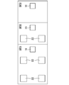
- FIG. 2 is a plan view showing an example of the arrangement of the indoor unit and the air supply port in each target space.
- FIG. 3 is a diagram corresponding to FIG. 2 relating to the air conditioning system of another embodiment.
- the air conditioning system (100) of the present embodiment is a system that realizes air conditioning in an indoor space included in a building such as a house, a building, a factory, or a public facility.
- the air conditioning system (100) of the present embodiment is applied to a building (BL) including a plurality of (for example, two) indoor spaces (SP1, SP2).
- the plurality of indoor spaces (SP1, SP2) may be a plurality of spaces completely partitioned by a wall or the like, or may be a plurality of spaces simply partitioned by a tsuitate or the like.
- the building (BL) is exclusively occupied by the machine room (BL1) where the outside air treatment device (10) described later is arranged, the exclusive section (BL2) where the indoor spaces (SP1, SP2) are located, and the machine room (BL1). It has a corridor (BL3) that intervenes with the section (BL2).
- all the indoor spaces are the target spaces (SP1, SP2) in which the indoor unit (22) of the air conditioner (20) described later is installed. Is.
- the air conditioning system (100) includes an outside air treatment device (10), an air conditioner (20), and a control device (30).
- the outside air treatment device (10) adjusts the temperature and humidity of the taken in outside air (OA) to supply air to the target space (SP1, SP2).
- the outside air (OA) is the air outside the target space (SP1, SP2) (in this example, the air outside the building (BL)).
- the air conditioner (20) adjusts the temperature of the air (inside air) in the target space (SP1, SP2).
- the control device (30) constitutes a control unit.
- the operating states of the outside air processing device (10) and the air conditioner (20) can be switched by appropriately inputting commands to the remote controllers (40) installed in the target space (SP1, SP2). ..
- the control device (30) responds to the commands (commands related to start / stop, operation type, set temperature, set air volume, etc.) input to the remote controller (40), and the temperature, humidity, etc. of the outside air (OA) and inside air. Controls the operating conditions of the outside air treatment device (10) and the air conditioner (20).
- the outside air treatment device (10) mainly includes an air handling unit (11) (hereinafter referred to as an “air conditioner unit”) and a chiller unit (not shown) as a heat source unit.
- the air han unit (11) may be of a water type or a refrigerant type (direct expansion air han).
- the outside air treatment device (10) takes in the outside air (OA) from the intake port (15) provided on the outer wall of the building (BL) to the air conditioner unit (11) via the intake duct (L1) during operation.
- the outside air treatment device (10) cools or heats the taken in outside air (OA), dehumidifies or humidifies it, and passes through the air supply duct (L2) from the air supply port (16) to the target space (SP1, SP2). Is supplied as air supply (SOA).
- the outside air treatment device (10) is exhausted (EA) from the exhaust port (not shown) of the target space (SP1, SP2) to the outside of the building (BL) via the exhaust duct (L3) by the exhaust fan (17). ) Is released.
- the air conditioner unit (11) mainly includes an outside air heat exchanger (12), a humidifier (13), and an air supply fan (14).
- the outside air heat exchanger (12) has a heat transfer tube and heat transfer fins.
- the humidifier (13) humidifies the outside air (OA) that has passed through the outside air heat exchanger (12).
- the method and model of the humidifier (13) are not particularly limited, but for example, a general natural evaporation type (vaporization type) humidifier may be used.
- the air supply fan (14) is a blower that takes in the outside air (OA) into the air conditioner unit (11) and sends it to the air supply duct (L2).
- the type of the air supply fan (14) is not particularly limited, but for example, a sirocco fan may be used.
- the air supply fan (14) has a fan motor, and the rotation speed is adjusted by controlling the fan motor with an inverter. In this way, the air supply fan (14) has a variable air volume.
- the air han unit (11) includes various sensors, for example, an outside air temperature sensor and an outside air humidity sensor that detect the temperature and humidity of the outside air (OA) sucked into the air han unit (11), and an air supply duct (L2).
- a supply air temperature sensor or the like that detects the temperature (supply air temperature) of the supply air (SOA) sent to the target space (SP1, SP2) is arranged.
- the air supply duct (L2) is a member that forms a flow path for outside air (OA).
- One end of the air supply duct (L2) is connected to the air conditioner unit (11) so that the outside air (OA) flows in by driving the air supply fan (14).
- the other end of the air supply duct (L2) is branched into a plurality of branches, and each branch destination communicates with the target space (SP1, SP2).
- the other end (each branch destination) of the air supply duct (L2) is connected to the air supply port (16) formed on the ceiling of the target space (SP1, SP2).
- one air supply port (16) is provided in each target space (SP1, SP2).
- Each air supply port (16) is provided with a damper (not shown) for adjusting the air volume.
- any number of air supply ports (16) may be provided in each target space (SP1, SP2).
- the outside air processing device (10) includes an external air conditioner control unit (31) that controls the operation of each part included in the outside air processing device (10).
- the external controller control unit (31) is composed of a CPU, a memory, various electrical components, and the like.
- the external controller control unit (31) is connected to each device included in the external air processing device (10) via wiring.
- the external controller control unit (31) is electrically connected to the control device (30) and the remote controller (40) via a communication line.
- the external controller control unit (31) is configured by electrically connecting the microcomputers and electrical components arranged in the air conditioner unit (11) and the chiller unit to each other.
- the external controller control unit (31) sets a target value of the supply air temperature according to the set temperature, etc., and appropriately adjusts the operation of each unit based on the target value. As a result, the operating capacity (air conditioning capacity) of the outside air treatment device (10) is appropriately changed.
- the target value of the supply air temperature may be set by the control device (30).
- the air conditioner (20) includes a refrigerant circuit (not shown), and cools, dehumidifies, or dehumidifies the target space (SP1, SP2) by circulating the refrigerant in the refrigerant circuit to perform a vapor compression refrigeration cycle. Achieve air conditioning such as heating.
- the air conditioner (20) has a plurality of operation modes, and operates according to the operation modes. Specifically, the air conditioner (20) performs operations such as a cooling operation for cooling, a heating operation for heating, and a defrost operation for defrosting.
- the air conditioner (20) mainly has one outdoor unit (21) as a heat source unit and a plurality of (for example, six) indoor units (22).
- the type of the air conditioner (20) is not particularly limited, but for example, a variable refrigerant flow rate control (VRV) type may be used.
- VRV variable refrigerant flow rate control
- the refrigerant circuit is configured by connecting the outdoor unit (21) and each indoor unit (22) via the refrigerant connecting pipe (23).
- the type of the refrigerant sealed in the refrigerant circuit is not particularly limited, but an HFC refrigerant such as R32 or R410A may be used.
- the outdoor unit (21) is placed outside the target space (SP1, SP2) (in this example, outside the building (BL)).
- the outdoor unit (21) mainly includes a compressor, a four-way switching valve, an outdoor heat exchanger, an outdoor expansion valve, and an outdoor fan.
- a compressor is a device that compresses a low-pressure refrigerant in a refrigeration cycle until it reaches a high pressure.
- the four-way switching valve is a flow path switching means for switching the flow direction of the refrigerant in the refrigerant circuit.
- the outdoor heat exchanger is a heat exchanger that exchanges heat between the passing air flow (outdoor air flow generated by the outdoor fan) and the refrigerant.
- the outdoor heat exchanger functions as a refrigerant evaporator during normal cycle operation (heating operation) and as a refrigerant condenser or radiator during reverse cycle operation (cooling operation or defrost operation).
- the outdoor expansion valve is a valve that functions as a refrigerant pressure reducing means or a flow rate adjusting means, for example, an electric expansion valve capable of controlling the opening degree, and is arranged between the outdoor heat exchanger and the liquid side refrigerant connecting pipe.
- the outdoor fan is a blower that generates an outdoor air flow.
- the outdoor air flow is the flow of outside air that flows into the outdoor unit (21), passes through the outdoor heat exchanger, and flows out to the outside of the outdoor unit (21).
- the outdoor air flow is a heating source for the refrigerant in the outdoor heat exchanger during the normal cycle operation and a cooling source for the refrigerant in the outdoor heat exchanger during the reverse cycle operation.
- the outdoor fan includes a fan motor, and the rotation speed is adjusted by controlling the fan motor with an inverter. In this way, the outdoor fan has a variable air volume.
- the outdoor unit (21) is provided with various sensors, for example, a suction pressure sensor that detects the pressure of the refrigerant sucked into the compressor, a discharge pressure sensor that detects the pressure of the refrigerant discharged from the compressor, and the like. Will be done.
- Each indoor unit (22) is placed in the corresponding target space (SP1, SP2).
- six indoor units (22) are connected in parallel to one outdoor unit (21).
- four indoor units (22) are provided in one target space (SP1), and two indoor units (22) are provided in the other target space (SP2).
- any number of indoor units (22) may be provided in each target space (SP1, SP2).
- the model of each indoor unit (22) is not particularly limited, but for example, a ceiling-embedded type installed on the ceiling of the target space (SP1, SP2) may be used.
- each indoor unit (22) is installed so that the suction port and the air outlet are exposed from the ceiling in the target space (SP1, SP2).
- Each indoor unit (22) mainly has an indoor heat exchanger, an indoor expansion valve, and an indoor fan.
- the indoor heat exchanger is a heat exchanger that exchanges heat between the passing air flow (indoor air flow generated by the indoor fan) and the refrigerant.
- the indoor heat exchanger functions as a refrigerant condenser or radiator during normal cycle operation and as a refrigerant evaporator during reverse cycle operation.
- the indoor expansion valve is a valve that functions as a refrigerant pressure reducing means or a flow rate adjusting means, for example, an electric expansion valve capable of controlling the opening degree, and is arranged between the indoor heat exchanger and the liquid side refrigerant connecting pipe.
- the indoor fan is a blower that generates an indoor air flow.
- the indoor air flow is the flow of the inside air that flows into the indoor unit (22), passes through the indoor heat exchanger, and flows out to the outside of the indoor unit (22).
- the indoor air flow is a cooling source for the refrigerant in the indoor heat exchanger during the normal cycle operation and a heating source for the refrigerant in the indoor heat exchanger during the reverse cycle operation.
- the indoor fan includes a fan motor, and the rotation speed is adjusted by controlling the fan motor with an inverter. In this way, the indoor fan has a variable air volume.
- Each indoor unit (22) has various sensors, for example, an indoor temperature sensor for detecting the temperature, humidity, and carbon dioxide concentration of the indoor air flow (inside air) sucked into the indoor unit (22), and indoor humidity.
- a sensor for example, a carbon dioxide concentration sensor, a refrigerant temperature sensor for detecting the temperature of the refrigerant in the indoor heat exchanger, and the like are arranged.
- the air conditioner (20) has an air conditioner control unit (32) that controls the operation of each part included in the air conditioner (20).
- the air conditioner control unit (32) is composed of a CPU, a memory, various electrical components, and the like.
- the air conditioner control unit (32) is connected to each device included in the air conditioner (20) via wiring.
- the air conditioner control unit (32) is electrically connected to various sensors arranged in each indoor unit (22).
- the air conditioner control unit (32) is communicably connected to the remote controller (40) installed in the target space (SP1, SP2).
- the air conditioner control unit (32) is electrically connected to the control device (30) and the remote controller (40) via a communication line.
- the air conditioner control unit (32) is configured by electrically connecting each microcomputer and each electrical component arranged in the outdoor unit (21) and each indoor unit (22) to each other. To.
- the air conditioner control unit (32) sets a target value of the evaporation temperature in each indoor unit (22) according to the set temperature, indoor temperature, etc., and based on the target value, the capacity of the compressor, the air volume of the outdoor fan, etc. Is adjusted as appropriate. As a result, the operating capacity (air conditioning capacity) of the air conditioner (20) is appropriately changed.
- the target value of the evaporation temperature may be set by the control device (30).
- the control device (30) is a functional unit that comprehensively controls the operation of the air conditioning system (100), and specifically includes a computer composed of a memory, a CPU, etc., and the computer executes a program. As a result, each function of the air conditioning system (100) is carried out.
- the program is recorded on a computer-readable recording medium, such as a ROM.
- the control device (30) is electrically connected to the external air conditioner control unit (31) and the air conditioner control unit (32), and transmits and receives signals to and from each other.
- the control device (30) transmits a predetermined signal (for example, a control signal for setting a target air supply temperature and a target evaporation temperature) to the external air conditioner control unit (31) and the air conditioner control unit (32).
- the operation of each device constituting the outside air processing device (10) and the air conditioner (20) can be controlled.
- the control device (30) includes the detection values of various sensors arranged in the external air conditioner control unit (31) and the air conditioner control unit (32), as well as the outside air processing device (10) and the air conditioner (20). It is possible to acquire information that identifies each operating state.
- the remote controller (40) inputs various commands for the user to individually switch the operating states (start / stop, operation type, set temperature, set humidity, set air volume, etc.) of the outside air processing device (10) and the air conditioner (20). It is an input device for.
- the remote controller (40) also functions as a display device for displaying predetermined information (for example, the operating state of the outside air processing device (10) and the air conditioner (20), the temperature and humidity of the inside air and the outside air, etc.).
- the operation operation of the air conditioning system (100) will be described.
- the air conditioning system (100) of the present embodiment can selectively execute the common cooling operation and the common heating operation. The selection of each operation is made by the controller (30).
- the operation operations that can be performed by the air conditioning system (100) are not limited to these.
- the common cooling operation is an operation operation in which the outside air treatment device (10) and the air conditioner (20) execute the cooling operation. Specifically, in the common cooling operation, the outside air processing device (10) executes the outside air cooling operation (cooling operation using the outside air (OA) lower than the room temperature), and the air conditioner (20) performs the cooling operation. To execute.
- the target space (SP1, SP2) may or may not be dehumidified.
- the air supply fan (14) is operated in the outside air treatment device (10), whereby the outside air (OA) is taken into the air conditioner unit (11) via the intake port (15).
- the outside air (OA) taken into the air conditioner unit (11) is blown out to each target space (SP1, SP2) through each air supply port (16).
- the control device (30) adjusts the total air volume of the outside air processing device (10) by adjusting the rotation speed of the air supply fan (14), and also adjusts the opening degree of the damper of each air supply port (16). By doing so, the air volume for each target space (SP1, SP2) is adjusted.
- the reverse cycle operation is performed in the air conditioner (20), and the inside air cooled by the indoor unit (22) of each target space (SP1, SP2) is the target space (SP1, SP2). It is blown out to.
- the control device (30) controls each device constituting the air conditioner (20) to set the evaporation temperature in each indoor unit (22) to its target value (in other words, a heat medium in each indoor unit (22)). (Required temperature).
- the load factor of each indoor unit (22) (specifically, the ratio of the load of the indoor unit (22) to the rated capacity of each indoor unit (22)) is higher as the target value of the evaporation temperature is lower. Further, the load factor of the indoor unit (22) in operation is higher than the load factor of the indoor unit (22) in rest.
- control device (30) adjusts the air volume for each target space (SP1, SP2) of the outside air processing device (10) so that the power consumption of the air conditioning system (100) is reduced.
- the control device (30) targets the evaporation temperature when increasing the total air volume of the outside air processing device (10) during the common cooling operation (in other words, when increasing the rotation speed of the air supply fan (14)).
- the increased air volume of the target space (SP1, SP2) provided with the indoor unit (22) having a relatively low value is measured by the target space (SP1) provided with the indoor unit (22) having a relatively high evaporation temperature target value.
- SP2 Increase the air volume or more.
- the control device (30) measures the increased air volume of the target space (SP1, SP2) provided with the indoor unit (22) whose evaporation temperature target value is relatively low, and the evaporation temperature target value is relatively low. It may be larger than the increased air volume of the target space (SP1, SP2) provided with the high indoor unit (22).
- the target value of the evaporation temperature of each indoor unit (22) in one target space (SP1) is larger than the target value of the evaporation temperature of each indoor unit (22) in the other target space (SP2). Is also low.
- the control device (30) sets the increased air volume of one target space (SP1) to be equal to or greater than the increased air volume of the other target space (SP2).
- the increased air volume of the target space (SP1, SP2) is the amount of increase when the air volume of the outside air treatment device (10) for each target space (SP1, SP2) increases.
- the increased air volume of the target space (SP1, SP2) is the required air volume for each target space (SP1, SP2) (for example, the air volume obtained based on the carbon dioxide concentration of the target space (SP1, SP2)). This is the amount of increase when the total air volume of the outside air treatment device (10) is further increased when the treatment device (10) supplies the air.
- the control device (30) increases the total air volume of the outside air treatment device (10) during the common cooling operation
- the control device (30) is a target space (SP1, SP2) provided with an operating indoor unit (22).
- the control device (30) applies the increased air volume of the target space (SP1, SP2) provided with the operating indoor unit (22) to the target space provided with the stationary indoor unit (22). It may be larger than the increased air volume of (SP1, SP2).
- each indoor unit (22) in one target space (SP1) is operating and each indoor unit (22) in the other target space (SP2) is inactive.
- the control device (30) sets the increased air volume of one target space (SP1) to be equal to or greater than the increased air volume of the other target space (SP2).
- the common heating operation is an operation in which the outside air treatment device (10) and the air conditioner (20) execute the heating operation. Specifically, in the common heating operation, the outside air processing device (10) executes the outside air heating operation (heating operation using the outside air (OA) having a temperature higher than the room temperature), and the air conditioner (20) performs the heating operation. To execute. In the common heating operation, the target space (SP1, SP2) may or may not be humidified.
- the air supply fan (14) is operated in the outside air treatment device (10), whereby the outside air (OA) is taken into the air conditioner unit (11) via the intake port (15).
- the outside air (OA) taken into the air conditioner unit (11) is blown out to each target space (SP1, SP2) through each air supply port (16).
- the control device (30) adjusts the total air volume of the outside air processing device (10) by adjusting the rotation speed of the air supply fan (14), and also adjusts the opening degree of the damper of each air supply port (16). By doing so, the air volume for each target space (SP1, SP2) is adjusted.
- the air conditioner (20) performs a normal cycle operation, and the inside air heated by the indoor unit (22) of each target space (SP1, SP2) is the target space (SP1, SP2). It is blown out to.
- the control device (30) controls each device constituting the air conditioner (20) to set the condensation temperature in each indoor unit (22) to its target value (in other words, the heat medium in each indoor unit (22)). (Required temperature).
- the load factor of each indoor unit (22) is higher as the target value of the condensation temperature is higher. Further, the load factor of the indoor unit (22) in operation is higher than the load factor of the indoor unit (22) in rest.
- control device (30) adjusts the air volume for each target space (SP1, SP2) of the outside air treatment device (10) so that the power consumption of the air conditioning system (100) is reduced.
- the control device (30) is a target space provided with an indoor unit (22) having a relatively high target value of the condensation temperature when the total air volume of the outside air treatment device (10) is increased during the common heating operation.
- the increased air volume of (SP1, SP2) should be equal to or greater than the increased air volume of the target space (SP1, SP2) provided with the indoor unit (22) whose target value of the condensation temperature is relatively low.
- the control device (30) measures the increased air volume of the target space (SP1, SP2) provided with the indoor unit (22) having a relatively high target value of the condensation temperature, and the target value of the condensation temperature is relatively high. It may be larger than the increased air volume of the target space (SP1, SP2) provided with the low indoor unit (22).
- the target value of the condensation temperature of each indoor unit (22) in one target space (SP1) is larger than the target value of the condensation temperature of each indoor unit (22) in the other target space (SP2). Is also expensive.
- the control device (30) sets the increased air volume of one target space (SP1) to be equal to or greater than the increased air volume of the other target space (SP2).
- control device (30) increases the total air volume of the outside air treatment device (10) during the common heating operation
- the control device (30) is provided with the operating indoor unit (22) in the target space (SP1, SP2).
- the control device (30) applies the increased air volume of the target space (SP1, SP2) provided with the operating indoor unit (22) to the target space provided with the stationary indoor unit (22). It may be larger than the increased air volume of (SP1, SP2).
- each indoor unit (22) in one target space (SP1) is operating and each indoor unit (22) in the other target space (SP2) is inactive.
- the control device (30) sets the increased air volume of one target space (SP1) to be equal to or greater than the increased air volume of the other target space (SP2).
- the air conditioning system (100) of the present embodiment includes an outside air treatment device (10) that adjusts the temperature of the taken-in outside air to supply air to a plurality of target spaces (SP1, SP2), and each of the above target spaces (SP1, SP2).
- Each of the air conditioner (20) and the outside air treatment device (10) which have a plurality of indoor units (22) provided in the above-mentioned target space (SP1 and SP2) and adjust the temperature of the air in the target space (SP1 and SP2). It is provided with a control device (30) that adjusts the air volume with respect to the target space (SP1, SP2) so that the power consumption of the air conditioning system (100) is reduced according to the operating state of each indoor unit (22). ..
- the control device (30) of the present embodiment is set in each target space (SP1, SP1) of the outside air processing device (10) so that the power consumption of the air conditioning system (100) is reduced according to the operating state of each indoor unit (22). Adjust the air volume for SP2). By the operation of this control device (30), the power consumption of the air conditioning system (100) can be reduced.
- the ratio of the load of the indoor unit (22) to the rated capacity of the indoor unit (22) is set as the load factor of the indoor unit (22), and each target space (SP1) , SP2), the increase amount when the air volume of the outside air treatment device (10) increases is used as the increase air volume of the target space (SP1, SP2), and the control device (30) is the outside air treatment device (10).
- the increased air volume of the target space (SP1, SP2) provided with the indoor unit (22) having a relatively high load factor is used as the indoor unit (SP1 and SP2) having a relatively low load factor. Make it equal to or greater than the increased air volume of the above target space (SP1, SP2) where 22) is provided.
- the control device (30) of the present embodiment refers to the target space (SP1, SP2) provided with the indoor unit (22) having a relatively high load factor when increasing the total air volume of the outside air treatment device (10). Priority is given to increasing the air volume.
- this control device (30) By the operation of this control device (30), the variation in the load factor of each indoor unit (22) is reduced, and the power consumption of the air conditioning system (100) is reduced.
- Embodiment 1 (3)- In the air conditioning system (100) of the present embodiment, when the load factor of the indoor unit (22) is such that the air conditioner (20) cools the target space (SP1, SP2), the indoor unit (22) When the air conditioner (20) heats the target space (SP1, SP2), the higher the required temperature of the heat medium in the indoor unit (22), the higher the required temperature of the heat medium. Assuming that the temperature becomes higher, when the control device (30) increases the total air volume of the outside air treatment device (10) when the air conditioner (20) cools the target space (SP1, SP2), heat is generated.
- the indoor unit (22) provided with the indoor unit (22) having a relatively low required temperature of the medium is provided with an increased air volume of the target space (SP1, SP2) provided with the indoor unit (22) having a relatively high required temperature of the heat medium.
- the air conditioner (20) heats the target space (SP1, SP2) while increasing the air volume of the target space (SP1, SP2) or more, the total air volume of the outside air treatment device (10)
- the air volume should be greater than or equal to the increased air volume in the target space (SP1, SP2) where the unit (22) is provided.
- the control device (30) of the present embodiment is a target space provided with an indoor unit (22) in which the required temperature of the heat medium is relatively low when the total air volume of the outside air treatment device (10) is increased during the cooling operation. Priority is given to increasing the air volume for (SP1, SP2). Further, this control device (30) is a target space provided with an indoor unit (22) in which the required temperature of the heat medium is relatively high when the total air volume of the outside air treatment device (10) is increased during the heating operation. Priority is given to increasing the air volume for SP1 and SP2).
- Embodiment 1 (4)-
- the load factor of the indoor unit (22) in operation is higher than the load factor of the indoor unit (22) in hibernation
- the control device (30) Increases the total air volume of the outside air treatment device (10), the increased air volume of the target space (SP1, SP2) provided with the operating indoor unit (22) is suspended.
- the air volume should be greater than or equal to the increased air volume of the target space (SP1, SP2) provided with the indoor unit (22).
- the control device (30) of the present embodiment gives priority to the air volume with respect to the target space (SP1, SP2) provided with the operating indoor unit (22). Increase. As a result, the variation in the load factor of each indoor unit (22) is reduced, and the power consumption of the air conditioning system (100) is reduced.
- Embodiment 2 The second embodiment will be described.
- the air conditioning system (100) of the present embodiment differs from the above-described first embodiment in the criteria for adjusting the air volume of each target space (SP1, SP2).
- SP1, SP2 target space
- the differences from the first embodiment will be mainly described.
- control device (30) adjusts the air volume for each target space (SP1, SP2) of the outside air processing device (10) so that the power consumption of the air conditioning system (100) is reduced.
- the control device (30) is a target provided with an indoor unit (22) having a relatively high set temperature or suction air temperature when increasing the total air volume of the outside air treatment device (10) during common cooling operation.
- Set the increased air volume in the space (SP1, SP2) to be equal to or greater than the increased air volume in the target space (SP1, SP2) provided with the indoor unit (22) whose set temperature or suction air temperature is relatively low.
- the control device (30) relatives the set temperature or the suction air temperature to the increased air volume of the target space (SP1, SP2) provided with the indoor unit (22) having a relatively high set temperature or suction air temperature. It may be larger than the increased air volume of the target space (SP1, SP2) provided with the relatively low indoor unit (22).
- the control device (30) sets the increased air volume of one target space (SP1) to be equal to or greater than the increased air volume of the other target space (SP2).
- control device (30) adjusts the air volume for each target space (SP1, SP2) of the outside air treatment device (10) so that the power consumption of the air conditioning system (100) is reduced.
- the control device (30) is a target provided with an indoor unit (22) having a relatively low set temperature or suction air temperature when increasing the total air volume of the outside air treatment device (10) during common heating operation.
- Set the increased air volume of the space (SP1, SP2) to be equal to or greater than the increased air volume of the target space (SP1, SP2) provided with the indoor unit (22) having a relatively high set temperature or suction air temperature.
- the control device (30) relatives the set temperature or the suction air temperature to the increased air volume of the target space (SP1, SP2) provided with the indoor unit (22) whose set temperature or suction air temperature is relatively low. It may be larger than the increased air volume of the target space (SP1, SP2) provided with the relatively high indoor unit (22).
- the suction air temperature of each indoor unit (22) in one target space (SP1) is lower than the suction air temperature of each indoor unit (22) in the other target space (SP2). ..
- the control device (30) sets the increased air volume of one target space (SP1) to be equal to or greater than the increased air volume of the other target space (SP2).
- the air conditioning system (100) of the present embodiment also has the same effect as that of the first embodiment.
- the amount of increase when the air volume of the outside air treatment device (10) with respect to each of the target spaces (SP1, SP2) increases is increased by the target space (SP1, SP2).
- the increased air volume of the target space (SP1, SP2) provided with the indoor unit (22) having a relatively high suction air temperature can be adjusted by the indoor unit (22) having a relatively low set temperature or suction air temperature.
- the air conditioner (20) heats the target space (SP1, SP2) while increasing the air volume of the target space (SP1, SP2) provided, the total amount of the outside air treatment device (10) is increased.
- the set temperature or the suction air temperature is relatively low.
- the set temperature or the suction air temperature is relatively high for the increased air volume in the target space (SP1, SP2) provided with the indoor unit (22).
- the air volume should be greater than or equal to the increased air volume of the target space (SP1, SP2) provided with the high indoor unit (22).
- the control device (30) of the present embodiment is a target provided with an indoor unit (22) having a relatively high set temperature or suction air temperature when increasing the total air volume of the outside air treatment device (10) during cooling operation. Priority is given to increasing the air volume for the space (SP1, SP2). Further, this control device (30) is a target space provided with an indoor unit (22) having a relatively low set temperature or suction air temperature when increasing the total air volume of the outside air treatment device (10) during heating operation. Priority is given to increasing the air volume for (SP1, SP2).
- Embodiment 3 The third embodiment will be described.
- the air conditioning system (100) of the present embodiment differs from the above-described first embodiment in the criteria for adjusting the air volume of each target space (SP1, SP2). Hereinafter, the differences from the first embodiment will be mainly described.
- control device (30) adjusts the air volume for each target space (SP1, SP2) of the outside air processing device (10) so that the power consumption of the air conditioning system (100) is reduced. ..
- the control device (30) is an indoor unit in which the difference between the set temperature and the suction air temperature is relatively large when increasing the total air volume of the outside air treatment device (10) during the common cooling operation or the common heating operation.
- the increased air volume of the target space (SP1, SP2) provided with (22) is that of the target space (SP1, SP2) provided with the indoor unit (22) in which the difference between the set temperature and the suction air temperature is relatively small. Increase the air volume or more.
- the control device (30) determines the increased air volume of the target space (SP1, SP2) provided with the indoor unit (22) in which the difference between the set temperature and the suction air temperature is relatively large, and sets the set temperature and the suction air.
- the difference from the temperature may be larger than the increased air volume of the target space (SP1, SP2) provided with the indoor unit (22).
- the difference between the set temperature of each indoor unit (22) in one target space (SP1) and the suction air temperature is the set temperature of each indoor unit (22) in the other target space (SP2). Is larger than the difference between the temperature and the suction air temperature.
- the control device (30) sets the increased air volume of one target space (SP1) to be equal to or greater than the increased air volume of the other target space (SP2).
- the air conditioning system (100) of the present embodiment also has the same effect as that of the first embodiment.
- the amount of increase when the air volume of the outside air treatment device (10) with respect to each of the target spaces (SP1, SP2) increases is increased by the target space (SP1, SP2).
- the indoor unit (22) is provided in which the difference between the set temperature and the suction air temperature is relatively large.
- the increased air volume of the target space (SP1, SP2) is equal to or greater than the increased air volume of the target space (SP1, SP2) provided with the indoor unit (22) in which the difference between the set temperature and the suction air temperature is relatively small.
- the control device (30) of the present embodiment is a target provided with an indoor unit (22) in which the difference between the set temperature and the suction air temperature is relatively large when the total air volume of the outside air treatment device (10) is increased. Priority is given to increasing the air volume for the space (SP1, SP2).
- this control device (30) By the operation of this control device (30), the air conditioning by the outside air treatment device (10) is efficiently performed, and the power consumption of the air conditioning system (100) is reduced.
- some of the indoor spaces (SP1 and SP2) are the indoor units (20) of the air conditioner (20). It may be the target space in which 22) is installed.
- each of the three indoor spaces (SP1, SP2, SP3) is provided with one air supply port (16).
- Each air supply port (16) is connected to an air conditioner unit (11) of an outside air treatment device (10) via an air supply duct (L2).
- the air conditioner unit (11) supplies outside air (OA) to all indoor spaces (SP1, SP2, SP3).
- the indoor unit (22) is installed in each of the first indoor space (SP1) and the second indoor space (SP2), while the indoor unit (22) is installed in the third indoor space (SP3). Is not installed.
- the first indoor space (SP1) and the second indoor space (SP2) are target spaces in which the indoor unit (22) is installed.
- control device (30) adjusts the increased air volume for the first indoor space (SP1) and the second indoor space (SP2), which are the target spaces, as described above.
- the control device (30) of the present modification may or may not adjust the increased air volume in the third indoor space (SP3) which is not the target space.
- this disclosure is useful for air conditioning systems.
- Air conditioner 10 Outside air treatment device 20 Air conditioner 22 Indoor unit 30 Control device (control unit) 100 Air conditioning system SP1, SP2 Target space
Landscapes
- Engineering & Computer Science (AREA)
- Combustion & Propulsion (AREA)
- General Engineering & Computer Science (AREA)
- Mechanical Engineering (AREA)
- Chemical & Material Sciences (AREA)
- Physics & Mathematics (AREA)
- Fluid Mechanics (AREA)
- Signal Processing (AREA)
- General Physics & Mathematics (AREA)
- Automation & Control Theory (AREA)
- Mathematical Physics (AREA)
- Fuzzy Systems (AREA)
- Air Conditioning Control Device (AREA)
- Ventilation (AREA)
Abstract
空調システム(100)は、外気処理装置(10)と空気調和装置(20)と制御部(30)とを備える。外気処理装置(10)は、取り入れた外気の温度を調整して複数の屋内空間に給気する。空気調和装置(20)は、複数の上記屋内空間の一部または全部である複数の対象空間(SP1,SP2)に少なくとも1つずつ設けられた室内ユニット(22)を有し、対象空間(SP1,SP2)の空気の温度を調整する。制御部(30)は、外気処理装置(10)の各対象空間(SP1,SP2)に対する風量を、各室内ユニット(22)の運転状態に応じて、空調システム(100)の消費電力が小さくなるように調節する。
Description
本開示は、空調システムに関するものである。
従来より、対象空間の空気調和を行う空調システムに適用される技術として、複数の吹出しユニットから対象空間に吹き出す調和空気の風量を各吹出しユニットごとに調節する技術が知られている(例えば、特許文献1)。
ところで、近年、そのような技術を適用した空調システムの消費電力を低減することに対する要求がますます高まっている。
本開示の目的は、空調システムの消費電力を低減することにある。
本開示の第1の態様は、取り入れた外気の温度を調整して複数の屋内空間に給気する外気処理装置(10)と、複数の上記屋内空間の一部または全部である複数の対象空間(SP1,SP2)に少なくとも1つずつ設けられた室内ユニット(22)を有し、上記対象空間(SP1,SP2)の空気の温度を調整する空気調和装置(20)とを備える空調システム(100)を対象とする。空調システム(100)は、上記外気処理装置(10)の各上記対象空間(SP1,SP2)に対する風量を、各上記室内ユニット(22)の運転状態に応じて、上記空調システム(100)の消費電力が小さくなるように調節する制御部(30)を備える。
第1の態様において、制御部(30)は、各室内ユニット(22)の運転状態に応じて、空調システム(100)の消費電力が小さくなるように外気処理装置(10)の各対象空間(SP1,SP2)に対する風量を調節する。この制御部(30)の動作により、空調システム(100)の消費電力を低減できる。
本開示の第2の態様は、上記第1の態様において、上記室内ユニット(22)の定格能力に対する該室内ユニット(22)の負荷の割合を該室内ユニット(22)の負荷率とし、かつ各上記対象空間(SP1,SP2)に対する上記外気処理装置(10)の風量が増加する際の増加量を該対象空間(SP1,SP2)の増加風量としたときに、上記制御部(30)は、上記外気処理装置(10)の総風量を増加させる場合、上記負荷率が相対的に高い上記室内ユニット(22)が設けられた上記対象空間(SP1,SP2)の増加風量を、上記負荷率が相対的に低い上記室内ユニット(22)が設けられた上記対象空間(SP1,SP2)の増加風量以上にすることを特徴とする。
第2の態様において、制御部(30)は、外気処理装置(10)の総風量を増加させる場合に、負荷率が相対的に高い室内ユニット(22)が設けられた対象空間(SP1,SP2)に対する風量を優先的に増加させる。この制御部(30)の動作により、各室内ユニット(22)の負荷率のばらつきが低減され、空調システム(100)の消費電力が低減される。
本開示の第3の態様は、上記第2の態様において、上記室内ユニット(22)の負荷率は、上記空気調和装置(20)が上記対象空間(SP1,SP2)の冷房を行う場合には、上記室内ユニット(22)における熱媒体の要求温度が低いほど高くなり、上記空気調和装置(20)が上記対象空間(SP1,SP2)の暖房を行う場合には、上記室内ユニット(22)における熱媒体の要求温度が高いほど高くなり、上記制御部(30)は、上記空気調和装置(20)が上記対象空間(SP1,SP2)の冷房を行う場合に上記外気処理装置(10)の総風量を増加させるとき、熱媒体の要求温度が相対的に低い上記室内ユニット(22)が設けられた上記対象空間(SP1,SP2)の増加風量を、熱媒体の要求温度が相対的に高い上記室内ユニット(22)が設けられた上記対象空間(SP1,SP2)の増加風量以上にする一方、上記空気調和装置(20)が上記対象空間(SP1,SP2)の暖房を行う場合に上記外気処理装置(10)の総風量を増加させるとき、熱媒体の要求温度が相対的に高い上記室内ユニット(22)が設けられた上記対象空間(SP1,SP2)の増加風量を、熱媒体の要求温度が相対的に低い上記室内ユニット(22)が設けられた上記対象空間(SP1,SP2)の増加風量以上にすることを特徴とする。
第3の態様において、制御部(30)は、冷房運転時に外気処理装置(10)の総風量を増加させる場合に、熱媒体の要求温度が相対的に低い室内ユニット(22)が設けられた対象空間(SP1,SP2)に対する風量を優先的に増加させる。また、制御部(30)は、暖房運転時に外気処理装置(10)の総風量を増加させる場合に、熱媒体の要求温度が相対的に高い室内ユニット(22)が設けられた対象空間(SP1,SP2)に対する風量を優先的に増加させる。これらの制御部(30)の動作により、各室内ユニット(22)の負荷率のばらつきが低減され、空調システム(100)の消費電力が低減される。
本開示の第4の態様は、上記第2の態様において、稼働している上記室内ユニット(22)の負荷率は、休止している上記室内ユニット(22)の負荷率よりも高く、上記制御部(30)は、上記外気処理装置(10)の総風量を増加させる場合、稼働している上記室内ユニット(22)が設けられた上記対象空間(SP1,SP2)の増加風量を、休止している上記室内ユニット(22)が設けられた上記対象空間(SP1,SP2)の増加風量以上にすることを特徴とする。
第4の態様において、制御部(30)は、外気処理装置(10)の総風量を増加させる場合に、稼働している室内ユニット(22)が設けられた対象空間(SP1,SP2)に対する風量を優先的に増加させる。この制御部(30)の動作により、各室内ユニット(22)の負荷率のばらつきが低減され、空調システム(100)の消費電力が低減される。
本開示の第5の態様は、上記第1~第4の態様のいずれか1つにおいて、各上記対象空間(SP1,SP2)に対する上記外気処理装置(10)の風量が増加する際の増加量を該対象空間(SP1,SP2)の増加風量としたときに、上記制御部(30)は、上記空気調和装置(20)が上記対象空間(SP1,SP2)の冷房を行う場合に上記外気処理装置(10)の総風量を増加させるとき、設定温度または吸込み空気温度が相対的に高い上記室内ユニット(22)が設けられた上記対象空間(SP1,SP2)の増加風量を、設定温度または吸込み空気温度が相対的に低い上記室内ユニット(22)が設けられた上記対象空間(SP1,SP2)の増加風量以上にする一方、上記空気調和装置(20)が上記対象空間(SP1,SP2)の暖房を行う場合に上記外気処理装置(10)の総風量を増加させるとき、設定温度または吸込み空気温度が相対的に低い上記室内ユニット(22)が設けられた上記対象空間(SP1,SP2)の増加風量を、設定温度または吸込み空気温度が相対的に高い上記室内ユニット(22)が設けられた上記対象空間(SP1,SP2)の増加風量以上にすることを特徴とする。
第5の態様において、制御部(30)は、冷房運転時に外気処理装置(10)の総風量を増加させる場合に、設定温度または吸込み空気温度が相対的に高い室内ユニット(22)が設けられた対象空間(SP1,SP2)に対する風量を優先的に増加させる。また、制御部(30)は、暖房運転時に外気処理装置(10)の総風量を増加させる場合に、設定温度または吸込み空気温度が相対的に低い室内ユニット(22)が設けられた対象空間(SP1,SP2)に対する風量を優先的に増加させる。これらの制御部(30)の動作により、外気処理装置(10)による空気調和が効率的に行われ、空調システム(100)の消費電力が低減される。
本開示の第6の態様は、上記第1~第4の態様のいずれか1つにおいて、各上記対象空間(SP1,SP2)に対する上記外気処理装置(10)の風量が増加する際の増加量を該対象空間(SP1,SP2)の増加風量としたときに、上記制御部(30)は、上記外気処理装置(10)の総風量を増加させる場合、設定温度と吸込み空気温度との差が相対的に大きい上記室内ユニット(22)が設けられた上記対象空間(SP1,SP2)の増加風量を、設定温度と吸込み空気温度との差が相対的に小さい上記室内ユニット(22)が設けられた上記対象空間(SP1,SP2)の増加風量以上にすることを特徴とする。
第6の態様において、制御部(30)は、外気処理装置(10)の総風量を増加させる場合に、設定温度と吸込み空気温度との差が相対的に大きい室内ユニット(22)が設けられた対象空間(SP1,SP2)に対する風量を優先的に増加させる。この制御部(30)の動作により、外気処理装置(10)による空気調和が効率的に行われ、空調システム(100)の消費電力が低減される。
《実施形態1》
実施形態1について説明する。本実施形態の空調システム(100)は、家屋、ビル、工場、公共施設などの建築物内に含まれる屋内空間において、空気調和を実現するシステムである。
実施形態1について説明する。本実施形態の空調システム(100)は、家屋、ビル、工場、公共施設などの建築物内に含まれる屋内空間において、空気調和を実現するシステムである。
図1に示すように、本実施形態の空調システム(100)は、複数(例えば、2つ)の屋内空間(SP1,SP2)を含む建物(BL)に適用される。複数の屋内空間(SP1,SP2)は、壁などによって完全に仕切られた複数の空間であってもよいし、衝立などによって簡易的に仕切られた複数の空間であってもよい。建物(BL)は、後述する外気処理装置(10)が配置される機械室(BL1)と、屋内空間(SP1,SP2)が存在する専有部区画(BL2)と、機械室(BL1)と専有部区画(BL2)との間に介在する廊下(BL3)とを有する。本実施形態の空調システム(100)が設置される建物(BL)では、全ての屋内空間が、後述する空気調和装置(20)の室内ユニット(22)が設置された対象空間(SP1,SP2)である。
空調システム(100)は、外気処理装置(10)と、空気調和装置(20)と、制御装置(30)とを備える。外気処理装置(10)は、取り入れた外気(OA)の温度および湿度を調整して対象空間(SP1,SP2)に給気する。外気(OA)は、対象空間(SP1,SP2)の外部の空気(この例では、建物(BL)の外部の空気)である。空気調和装置(20)は、対象空間(SP1,SP2)の空気(内気)の温度を調整する。制御装置(30)は、制御部を構成している。
空調システム(100)では、対象空間(SP1,SP2)に設置されるリモコン(40)にコマンドを適宜入力することで、外気処理装置(10)および空気調和装置(20)の運転状態を切り換えられる。制御装置(30)は、リモコン(40)に入力されたコマンド(発停、運転種別、設定温度、設定風量などに係るコマンド)、および外気(OA)や内気の温度、湿度などに応じて、外気処理装置(10)および空気調和装置(20)の運転状態を制御する。
〈外気処理装置の構成〉
外気処理装置(10)は、主として、エアハンドリングユニット(11)(以下、「エアハンユニット」という)と、熱源ユニットとなるチラーユニット(図示せず)とを備える。エアハンユニット(11)は、水方式でもよいし、冷媒方式(直膨エアハン)でもよい。
外気処理装置(10)は、主として、エアハンドリングユニット(11)(以下、「エアハンユニット」という)と、熱源ユニットとなるチラーユニット(図示せず)とを備える。エアハンユニット(11)は、水方式でもよいし、冷媒方式(直膨エアハン)でもよい。
外気処理装置(10)は、運転中、建物(BL)の外壁に設けられた吸気口(15)から吸気ダクト(L1)を経由して外気(OA)をエアハンユニット(11)に取り込む。外気処理装置(10)は、取り込んだ外気(OA)を冷却もしくは加熱、または除湿もしくは加湿して、給気ダクト(L2)を経由して給気口(16)から対象空間(SP1,SP2)に給気(SOA)として供給する。
外気処理装置(10)は、排気ファン(17)によって、対象空間(SP1,SP2)の排気口(図示せず)から排気ダクト(L3)を経由して建物(BL)の外部に排気(EA)を放出する。
エアハンユニット(11)は、主として、外気熱交換器(12)と、加湿器(13)と、給気ファン(14)とを備える。外気熱交換器(12)は、伝熱管および伝熱フィンを有する。
外気熱交換器(12)では、伝熱管および伝熱フィンの周囲を通過する外気(OA)と、伝熱管を通過する熱媒体との間で熱交換が行われる。加湿器(13)は、外気熱交換器(12)を通過した外気(OA)を加湿する。加湿器(13)の方式や型式は特に限定されないが、例えば、一般的な自然蒸発式(気化式)の加湿器を用いてもよい。
給気ファン(14)は、外気(OA)をエアハンユニット(11)内に取り込み、給気ダクト(L2)へ送る送風機である。給気ファン(14)の型式は特に限定されないが、例えば、シロッコファンを用いてもよい。給気ファン(14)は、ファンモータを有し、ファンモータがインバータ制御されることによって回転速度が調整される。このように、給気ファン(14)は、風量可変である。
エアハンユニット(11)には、各種センサ、例えば、エアハンユニット(11)に吸入される外気(OA)の温度および湿度を検出する外気温度センサおよび外気湿度センサ、ならびに給気ダクト(L2)に(対象空間(SP1,SP2)に)送られる給気(SOA)の温度(給気温度)を検出する給気温度センサなどが配置される。
給気ダクト(L2)は、外気(OA)の流路を形成する部材である。給気ダクト(L2)は、給気ファン(14)が駆動することで外気(OA)が流入するように、一端がエアハンユニット(11)に接続される。給気ダクト(L2)の他端は、複数に分岐しており、各分岐先において対象空間(SP1,SP2)に連通する。具体的に、給気ダクト(L2)の他端(各分岐先)は、対象空間(SP1,SP2)の天井に形成された給気口(16)に接続される。給気口(16)は、図2に示すように、各対象空間(SP1,SP2)に1つずつ設けられる。各給気口(16)には、風量を調整するためのダンパ(図示せず)が設けられる。なお、給気口(16)は、各対象空間(SP1,SP2)に1つ以上設けられていれば、各対象空間(SP1,SP2)にいくつ設けられてもよい。
外気処理装置(10)は、外気処理装置(10)に含まれる各部の動作を制御する外調機制御部(31)を備える。外調機制御部(31)は、CPUやメモリおよび各種電装品などで構成される。外調機制御部(31)は、外気処理装置(10)に含まれる各機器と配線を介して接続される。外調機制御部(31)は、通信線を介して制御装置(30)やリモコン(40)と電気的に接続される。本実施形態では、外調機制御部(31)は、エアハンユニット(11)やチラーユニットに配置されるマイクロコンピュータや各電装品が互いに電気的に接続されることで構成される。
外調機制御部(31)は、設定温度などに応じて、給気温度の目標値を設定し、当該目標値に基づき各部の動作を適宜調整する。これにより、外気処理装置(10)の運転容量(空調能力)が適宜変更される。なお、給気温度の目標値は、制御装置(30)によって設定されてもよい。
〈空気調和装置の構成〉
空気調和装置(20)は、冷媒回路(図示せず)を含み、冷媒回路において冷媒を循環させて蒸気圧縮式の冷凍サイクルを行うことにより、対象空間(SP1,SP2)の冷房、除湿、または暖房などの空気調和を実現する。空気調和装置(20)は、複数の運転モードを有しており、運転モードに応じた運転を行う。具体的に、空気調和装置(20)は、冷房を行う冷房運転、暖房を行う暖房運転、除霜を行うデフロスト運転などの運転を行う。
空気調和装置(20)は、冷媒回路(図示せず)を含み、冷媒回路において冷媒を循環させて蒸気圧縮式の冷凍サイクルを行うことにより、対象空間(SP1,SP2)の冷房、除湿、または暖房などの空気調和を実現する。空気調和装置(20)は、複数の運転モードを有しており、運転モードに応じた運転を行う。具体的に、空気調和装置(20)は、冷房を行う冷房運転、暖房を行う暖房運転、除霜を行うデフロスト運転などの運転を行う。
空気調和装置(20)は、主として、熱源ユニットとなる1台の室外ユニット(21)と、複数台(例えば、6台)の室内ユニット(22)とを有する。空気調和装置(20)の型式は特に限定されないが、例えば、可変冷媒流量制御(VRV)型のものを用いてもよい。
空気調和装置(20)では、室外ユニット(21)と各室内ユニット(22)とが、冷媒連絡管(23)を介して接続されることによって冷媒回路が構成される。冷媒回路に封入される冷媒の種類は特に限定されないが、例えばR32やR410AなどのHFC冷媒を用いてもよい。
室外ユニット(21)は、対象空間(SP1,SP2)の外部(この例では、建物(BL)の外部)に配置される。室外ユニット(21)は、主として、圧縮機と、四路切換弁と、室外熱交換器と、室外膨張弁と、室外ファンとを有する。
圧縮機は、冷凍サイクルにおける低圧の冷媒を高圧になるまで圧縮する機器である。四路切換弁は、冷媒回路における冷媒の流れ方向を切り換えるための流路切換手段である。室外熱交換器は、通過する空気流(室外ファンによって生成される室外空気流)と冷媒とを熱交換させる熱交換器である。室外熱交換器は、正サイクル運転(暖房運転)時には、冷媒の蒸発器として機能し、逆サイクル運転(冷房運転やデフロスト運転)時には、冷媒の凝縮器または放熱器として機能する。室外膨張弁は、冷媒の減圧手段または流量調整手段として機能する弁、例えば、開度制御が可能な電動膨張弁であり、室外熱交換器と液側冷媒連絡管との間に配置される。
室外ファンは、室外空気流を生成する送風機である。室外空気流は、室外ユニット(21)内に流入し、室外熱交換器を通過して室外ユニット(21)外に流出する外気の流れである。室外空気流は、正サイクル運転時における室外熱交換器内の冷媒の加熱源であり、逆サイクル運転時における室外熱交換器内の冷媒の冷却源である。室外ファンは、ファンモータを含み、ファンモータがインバータ制御されることによって回転速度が調整される。このように、室外ファンは、風量可変である。
なお、室外ユニット(21)には、各種センサ、例えば、圧縮機に吸入される冷媒の圧力を検出する吸入圧力センサや、圧縮機から吐出される冷媒の圧力を検出する吐出圧力センサなどが配置される。
各室内ユニット(22)は、対応する対象空間(SP1,SP2)に配置される。本実施形態では、1台の室外ユニット(21)に対して6台の室内ユニット(22)が互いに並列に接続される。室内ユニット(22)は、図2に示すように、一方の対象空間(SP1)に4台設けられ、他方の対象空間(SP2)に2台設けられる。なお、室内ユニット(22)は、各対象空間(SP1,SP2)に1台以上設けられていれば、各対象空間(SP1,SP2)にいくつ設けられてもよい。各室内ユニット(22)の型式は特に限定されないが、例えば、対象空間(SP1,SP2)の天井に設置される天井埋込型のものを用いてもよい。この場合、各室内ユニット(22)は、対象空間(SP1,SP2)において吸込口および吹出口が天井から露出するように設置される。
各室内ユニット(22)は、主として、室内熱交換器と、室内膨張弁と、室内ファンとを有する。
室内熱交換器は、通過する空気流(室内ファンによって生成される室内空気流)と冷媒とを熱交換させる熱交換器である。室内熱交換器は、正サイクル運転時には、冷媒の凝縮器または放熱器として機能し、逆サイクル運転時には、冷媒の蒸発器として機能する。室内膨張弁は、冷媒の減圧手段または流量調整手段として機能する弁、例えば、開度制御が可能な電動膨張弁であり、室内熱交換器と液側冷媒連絡管との間に配置される。
室内ファンは、室内空気流を生成する送風機である。室内空気流は、室内ユニット(22)内に流入し、室内熱交換器を通過して室内ユニット(22)外へ流出する内気の流れである。室内空気流は、正サイクル運転時における室内熱交換器内の冷媒の冷却源であり、逆サイクル運転時における室内熱交換器内の冷媒の加熱源である。室内ファンは、ファンモータを含み、ファンモータがインバータ制御されることによって回転速度が調整される。このように、室内ファンは、風量可変である。
なお、各室内ユニット(22)には、各種センサ、例えば、室内ユニット(22)内に吸入される室内空気流(内気)の温度、湿度、および二酸化炭素濃度を検出する室内温度センサ、室内湿度センサ、および二酸化炭素濃度センサ、ならびに室内熱交換器における冷媒の温度を検出する冷媒温度センサなどが配置される。
空気調和装置(20)は、空気調和装置(20)に含まれる各部の動作を制御する空調機制御部(32)を有する。空調機制御部(32)は、CPUやメモリおよび各種電装品などで構成される。空調機制御部(32)は、空気調和装置(20)に含まれる各機器と配線を介して接続される。空調機制御部(32)は、各室内ユニット(22)に配置される各種センサと電気的に接続される。空調機制御部(32)は、対象空間(SP1,SP2)に設置されるリモコン(40)と通信可能に接続される。空調機制御部(32)は、通信線を介して制御装置(30)およびリモコン(40)と電気的に接続される。
本実施形態では、空調機制御部(32)は、室外ユニット(21)および各室内ユニット(22)にそれぞれ配置される各マイクロコンピュータや各電装品が互いに電気的に接続されることによって構成される。空調機制御部(32)は、設定温度や室内温度などに応じて、各室内ユニット(22)において蒸発温度の目標値を設定し、当該目標値に基づき圧縮機の容量や室外ファンの風量などを適宜調整する。これにより、空気調和装置(20)の運転容量(空調能力)が適宜変更される。なお、蒸発温度の目標値は、制御装置(30)によって設定されてもよい。
〈制御装置およびリモコン〉
制御装置(30)は、空調システム(100)の動作を統括的に制御する機能部であり、具体的にはメモリやCPUなどで構成されるコンピュータを備えており、当該コンピュータがプログラムを実行することによって、空調システム(100)の各機能が実施される。プログラムは、コンピュータが読み取り可能な記録媒体、例えばROMなどに記録される。
制御装置(30)は、空調システム(100)の動作を統括的に制御する機能部であり、具体的にはメモリやCPUなどで構成されるコンピュータを備えており、当該コンピュータがプログラムを実行することによって、空調システム(100)の各機能が実施される。プログラムは、コンピュータが読み取り可能な記録媒体、例えばROMなどに記録される。
制御装置(30)は、外調機制御部(31)および空調機制御部(32)と電気的に接続されており、互いに信号の送受信を行う。制御装置(30)は、外調機制御部(31)および空調機制御部(32)に対して所定の信号(例えば、目標給気温度や目標蒸発温度を設定する制御信号)を送信することで、外気処理装置(10)および空気調和装置(20)のそれぞれを構成する各機器の動作を制御可能である。制御装置(30)は、外調機制御部(31)および空調機制御部(32)のそれぞれに配置された各種センサの検出値や、外気処理装置(10)および空気調和装置(20)のそれぞれの運転状態を特定する情報を取得可能である。
リモコン(40)は、ユーザが外気処理装置(10)および空気調和装置(20)の運転状態(発停、運転種別、設定温度、設定湿度、設定風量など)を個別に切り換える各種コマンドを入力するための入力装置である。リモコン(40)は、所定の情報(例えば、外気処理装置(10)や空気調和装置(20)の運転状態、内気や外気の温度や湿度など)を表示するための表示装置としても機能する。
〈空調システムの運転動作〉
空調システム(100)の運転動作について説明する。本実施形態の空調システム(100)は、共通冷房運転と、共通暖房運転とを選択的に実行できる。各運転の選択は、制御装置(30)によってなされる。なお、空調システム(100)が実行可能な運転動作は、これらに限らない。
空調システム(100)の運転動作について説明する。本実施形態の空調システム(100)は、共通冷房運転と、共通暖房運転とを選択的に実行できる。各運転の選択は、制御装置(30)によってなされる。なお、空調システム(100)が実行可能な運転動作は、これらに限らない。
《共通冷房運転》
共通冷房運転は、外気処理装置(10)および空気調和装置(20)が冷房運転を実行する運転動作である。具体的に、共通冷房運転では、外気処理装置(10)が外気冷房運転(室内温度よりも低温の外気(OA)を利用する冷房運転)を実行し、かつ空気調和装置(20)が冷房運転を実行する。なお、共通冷房運転では、対象空間(SP1,SP2)の除湿を行っても行わなくてもよい。
共通冷房運転は、外気処理装置(10)および空気調和装置(20)が冷房運転を実行する運転動作である。具体的に、共通冷房運転では、外気処理装置(10)が外気冷房運転(室内温度よりも低温の外気(OA)を利用する冷房運転)を実行し、かつ空気調和装置(20)が冷房運転を実行する。なお、共通冷房運転では、対象空間(SP1,SP2)の除湿を行っても行わなくてもよい。
-基本動作-
共通冷房運転では、外気処理装置(10)において、給気ファン(14)が運転され、それにより吸気口(15)を介してエアハンユニット(11)内に外気(OA)が取り入れられる。エアハンユニット(11)内に取り入れられた外気(OA)は、各給気口(16)を介して各対象空間(SP1,SP2)に吹き出される。制御装置(30)は、給気ファン(14)の回転速度を調整することで、外気処理装置(10)の総風量を調整すると共に、各給気口(16)のダンパの開度を調整することで、各対象空間(SP1,SP2)に対する風量を調整する。
共通冷房運転では、外気処理装置(10)において、給気ファン(14)が運転され、それにより吸気口(15)を介してエアハンユニット(11)内に外気(OA)が取り入れられる。エアハンユニット(11)内に取り入れられた外気(OA)は、各給気口(16)を介して各対象空間(SP1,SP2)に吹き出される。制御装置(30)は、給気ファン(14)の回転速度を調整することで、外気処理装置(10)の総風量を調整すると共に、各給気口(16)のダンパの開度を調整することで、各対象空間(SP1,SP2)に対する風量を調整する。
共通冷房運転では、空気調和装置(20)において、逆サイクル運転が行われ、それにより各対象空間(SP1,SP2)の室内ユニット(22)で冷却された内気が当該対象空間(SP1,SP2)に吹き出される。制御装置(30)は、空気調和装置(20)を構成する各機器を制御することで、各室内ユニット(22)における蒸発温度をその目標値(換言すると、各室内ユニット(22)における熱媒体の要求温度)に近づける。
ここで、各室内ユニット(22)の負荷率(具体的に、各室内ユニット(22)の定格能力に対する当該室内ユニット(22)の負荷の割合)は、蒸発温度の目標値が低いほど高い。また、稼働している室内ユニット(22)の負荷率は、休止している室内ユニット(22)の負荷率よりも高い。
-各対象空間に対する風量の調節-
共通冷房運転では、制御装置(30)が、外気処理装置(10)の各対象空間(SP1,SP2)に対する風量を、空調システム(100)の消費電力が小さくなるように調節する。
共通冷房運転では、制御装置(30)が、外気処理装置(10)の各対象空間(SP1,SP2)に対する風量を、空調システム(100)の消費電力が小さくなるように調節する。
具体例として、制御装置(30)は、共通冷房運転時に外気処理装置(10)の総風量を増加させる場合(換言すると、給気ファン(14)の回転速度を高める場合)、蒸発温度の目標値が相対的に低い室内ユニット(22)が設けられた対象空間(SP1,SP2)の増加風量を、蒸発温度の目標値が相対的に高い室内ユニット(22)が設けられた対象空間(SP1,SP2)の増加風量以上にする。この場合、制御装置(30)は、蒸発温度の目標値が相対的に低い室内ユニット(22)が設けられた対象空間(SP1,SP2)の増加風量を、蒸発温度の目標値が相対的に高い室内ユニット(22)が設けられた対象空間(SP1,SP2)の増加風量より多くしてもよい。
例えば、共通冷房運転において、一方の対象空間(SP1)の各室内ユニット(22)の蒸発温度の目標値が、他方の対象空間(SP2)の各室内ユニット(22)の蒸発温度の目標値よりも低いとする。この場合、制御装置(30)は、一方の対象空間(SP1)の増加風量を、他方の対象空間(SP2)の増加風量以上にする。
ここで、対象空間(SP1,SP2)の増加風量とは、各対象空間(SP1,SP2)に対する外気処理装置(10)の風量が増加する際の増加量である。特に、対象空間(SP1,SP2)の増加風量とは、各対象空間(SP1,SP2)に対して必要風量(例えば、対象空間(SP1,SP2)の二酸化炭素濃度に基づいて求まる風量)を外気処理装置(10)が供給している場合に、外気処理装置(10)の総風量をさらに増加させる際の増加量である。
別の具体例として、制御装置(30)は、共通冷房運転時に外気処理装置(10)の総風量を増加させる場合、稼働している室内ユニット(22)が設けられた対象空間(SP1,SP2)の増加風量を、休止している室内ユニット(22)が設けられた対象空間(SP1,SP2)の増加風量以上にする。この場合、制御装置(30)は、稼働している室内ユニット(22)が設けられた対象空間(SP1,SP2)の増加風量を、休止している室内ユニット(22)が設けられた対象空間(SP1,SP2)の増加風量より多くしてもよい。
例えば、共通冷房運転において、一方の対象空間(SP1)の各室内ユニット(22)が稼働し、かつ他方の対象空間(SP2)の各室内ユニット(22)が休止しているとする。この場合、制御装置(30)は、一方の対象空間(SP1)の増加風量を、他方の対象空間(SP2)の増加風量以上にする。
《共通暖房運転》
共通暖房運転は、外気処理装置(10)および空気調和装置(20)が暖房運転を実行する運転動作である。具体的に、共通暖房運転では、外気処理装置(10)が外気暖房運転(室内温度よりも高温の外気(OA)を利用する暖房運転)を実行し、かつ空気調和装置(20)が暖房運転を実行する。なお、共通暖房運転では、対象空間(SP1,SP2)の加湿を行っても行わなくてもよい。
共通暖房運転は、外気処理装置(10)および空気調和装置(20)が暖房運転を実行する運転動作である。具体的に、共通暖房運転では、外気処理装置(10)が外気暖房運転(室内温度よりも高温の外気(OA)を利用する暖房運転)を実行し、かつ空気調和装置(20)が暖房運転を実行する。なお、共通暖房運転では、対象空間(SP1,SP2)の加湿を行っても行わなくてもよい。
-基本動作-
共通暖房運転では、外気処理装置(10)において、給気ファン(14)が運転され、それにより吸気口(15)を介してエアハンユニット(11)内に外気(OA)が取り入れられる。エアハンユニット(11)内に取り入れられた外気(OA)は、各給気口(16)を介して各対象空間(SP1,SP2)に吹き出される。制御装置(30)は、給気ファン(14)の回転速度を調整することで、外気処理装置(10)の総風量を調整すると共に、各給気口(16)のダンパの開度を調整することで、各対象空間(SP1,SP2)に対する風量を調整する。
共通暖房運転では、外気処理装置(10)において、給気ファン(14)が運転され、それにより吸気口(15)を介してエアハンユニット(11)内に外気(OA)が取り入れられる。エアハンユニット(11)内に取り入れられた外気(OA)は、各給気口(16)を介して各対象空間(SP1,SP2)に吹き出される。制御装置(30)は、給気ファン(14)の回転速度を調整することで、外気処理装置(10)の総風量を調整すると共に、各給気口(16)のダンパの開度を調整することで、各対象空間(SP1,SP2)に対する風量を調整する。
共通暖房運転では、空気調和装置(20)において、正サイクル運転が行われ、それにより各対象空間(SP1,SP2)の室内ユニット(22)で加熱された内気が当該対象空間(SP1,SP2)に吹き出される。制御装置(30)は、空気調和装置(20)を構成する各機器を制御することで、各室内ユニット(22)における凝縮温度をその目標値(換言すると、各室内ユニット(22)における熱媒体の要求温度)に近づける。
ここで、各室内ユニット(22)の負荷率は、凝縮温度の目標値が高いほど高い。また、稼働している室内ユニット(22)の負荷率は、休止している室内ユニット(22)の負荷率よりも高い。
-各対象空間に対する風量の調節-
共通暖房運転では、制御装置(30)が、外気処理装置(10)の各対象空間(SP1,SP2)に対する風量を、空調システム(100)の消費電力が小さくなるように調節する。
共通暖房運転では、制御装置(30)が、外気処理装置(10)の各対象空間(SP1,SP2)に対する風量を、空調システム(100)の消費電力が小さくなるように調節する。
具体例として、制御装置(30)は、共通暖房運転時に外気処理装置(10)の総風量を増加させる場合、凝縮温度の目標値が相対的に高い室内ユニット(22)が設けられた対象空間(SP1,SP2)の増加風量を、凝縮温度の目標値が相対的に低い室内ユニット(22)が設けられた対象空間(SP1,SP2)の増加風量以上にする。この場合、制御装置(30)は、凝縮温度の目標値が相対的に高い室内ユニット(22)が設けられた対象空間(SP1,SP2)の増加風量を、凝縮温度の目標値が相対的に低い室内ユニット(22)が設けられた対象空間(SP1,SP2)の増加風量より多くしてもよい。
例えば、共通暖房運転において、一方の対象空間(SP1)の各室内ユニット(22)の凝縮温度の目標値が、他方の対象空間(SP2)の各室内ユニット(22)の凝縮温度の目標値よりも高いとする。この場合、制御装置(30)は、一方の対象空間(SP1)の増加風量を、他方の対象空間(SP2)の増加風量以上にする。
別の具体例として、制御装置(30)は、共通暖房運転時に外気処理装置(10)の総風量を増加させる場合、稼働している室内ユニット(22)が設けられた対象空間(SP1,SP2)の増加風量を、休止している室内ユニット(22)が設けられた対象空間(SP1,SP2)の増加風量以上にする。この場合、制御装置(30)は、稼働している室内ユニット(22)が設けられた対象空間(SP1,SP2)の増加風量を、休止している室内ユニット(22)が設けられた対象空間(SP1,SP2)の増加風量より多くしてもよい。
例えば、共通暖房運転において、一方の対象空間(SP1)の各室内ユニット(22)が稼働し、かつ他方の対象空間(SP2)の各室内ユニット(22)が休止しているとする。この場合、制御装置(30)は、一方の対象空間(SP1)の増加風量を、他方の対象空間(SP2)の増加風量以上にする。
-実施形態1の効果(1)-
本実施形態の空調システム(100)は、取り入れた外気の温度を調整して複数の対象空間(SP1,SP2)に給気する外気処理装置(10)と、各上記対象空間(SP1,SP2)に少なくとも1つずつ設けられる複数の室内ユニット(22)を有し、上記対象空間(SP1,SP2)の空気の温度を調整する空気調和装置(20)と、上記外気処理装置(10)の各上記対象空間(SP1,SP2)に対する風量を、各上記室内ユニット(22)の運転状態に応じて、上記空調システム(100)の消費電力が小さくなるように調節する制御装置(30)とを備える。
本実施形態の空調システム(100)は、取り入れた外気の温度を調整して複数の対象空間(SP1,SP2)に給気する外気処理装置(10)と、各上記対象空間(SP1,SP2)に少なくとも1つずつ設けられる複数の室内ユニット(22)を有し、上記対象空間(SP1,SP2)の空気の温度を調整する空気調和装置(20)と、上記外気処理装置(10)の各上記対象空間(SP1,SP2)に対する風量を、各上記室内ユニット(22)の運転状態に応じて、上記空調システム(100)の消費電力が小さくなるように調節する制御装置(30)とを備える。
本実施形態の制御装置(30)は、各室内ユニット(22)の運転状態に応じて、空調システム(100)の消費電力が小さくなるように外気処理装置(10)の各対象空間(SP1,SP2)に対する風量を調節する。この制御装置(30)の動作により、空調システム(100)の消費電力を低減できる。
-実施形態1の効果(2)-
本実施形態の空調システム(100)は、上記室内ユニット(22)の定格能力に対する該室内ユニット(22)の負荷の割合を該室内ユニット(22)の負荷率とし、かつ各上記対象空間(SP1,SP2)に対する上記外気処理装置(10)の風量が増加する際の増加量を該対象空間(SP1,SP2)の増加風量として、上記制御装置(30)が、上記外気処理装置(10)の総風量を増加させる場合、上記負荷率が相対的に高い上記室内ユニット(22)が設けられた上記対象空間(SP1,SP2)の増加風量を、上記負荷率が相対的に低い上記室内ユニット(22)が設けられた上記対象空間(SP1,SP2)の増加風量以上にする。
本実施形態の空調システム(100)は、上記室内ユニット(22)の定格能力に対する該室内ユニット(22)の負荷の割合を該室内ユニット(22)の負荷率とし、かつ各上記対象空間(SP1,SP2)に対する上記外気処理装置(10)の風量が増加する際の増加量を該対象空間(SP1,SP2)の増加風量として、上記制御装置(30)が、上記外気処理装置(10)の総風量を増加させる場合、上記負荷率が相対的に高い上記室内ユニット(22)が設けられた上記対象空間(SP1,SP2)の増加風量を、上記負荷率が相対的に低い上記室内ユニット(22)が設けられた上記対象空間(SP1,SP2)の増加風量以上にする。
本実施形態の制御装置(30)は、外気処理装置(10)の総風量を増加させる場合に、負荷率が相対的に高い室内ユニット(22)が設けられた対象空間(SP1,SP2)に対する風量を優先的に増加させる。この制御装置(30)の動作により、各室内ユニット(22)の負荷率のばらつきが低減され、空調システム(100)の消費電力が低減される。
-実施形態1の効果(3)-
本実施形態の空調システム(100)は、上記室内ユニット(22)の負荷率が、上記空気調和装置(20)が上記対象空間(SP1,SP2)の冷房を行う場合、上記室内ユニット(22)における熱媒体の要求温度が低いほど高くなるとし、上記空気調和装置(20)が上記対象空間(SP1,SP2)の暖房を行う場合、上記室内ユニット(22)における熱媒体の要求温度が高いほど高くなるとして、上記制御装置(30)が、上記空気調和装置(20)が上記対象空間(SP1,SP2)の冷房を行う場合に上記外気処理装置(10)の総風量を増加させるとき、熱媒体の要求温度が相対的に低い上記室内ユニット(22)が設けられた上記対象空間(SP1,SP2)の増加風量を、熱媒体の要求温度が相対的に高い上記室内ユニット(22)が設けられた上記対象空間(SP1,SP2)の増加風量以上にする一方、上記空気調和装置(20)が上記対象空間(SP1,SP2)の暖房を行う場合に上記外気処理装置(10)の総風量を増加させるとき、熱媒体の要求温度が相対的に高い上記室内ユニット(22)が設けられた上記対象空間(SP1,SP2)の増加風量を、熱媒体の要求温度が相対的に低い上記室内ユニット(22)が設けられた上記対象空間(SP1,SP2)の増加風量以上にする。
本実施形態の空調システム(100)は、上記室内ユニット(22)の負荷率が、上記空気調和装置(20)が上記対象空間(SP1,SP2)の冷房を行う場合、上記室内ユニット(22)における熱媒体の要求温度が低いほど高くなるとし、上記空気調和装置(20)が上記対象空間(SP1,SP2)の暖房を行う場合、上記室内ユニット(22)における熱媒体の要求温度が高いほど高くなるとして、上記制御装置(30)が、上記空気調和装置(20)が上記対象空間(SP1,SP2)の冷房を行う場合に上記外気処理装置(10)の総風量を増加させるとき、熱媒体の要求温度が相対的に低い上記室内ユニット(22)が設けられた上記対象空間(SP1,SP2)の増加風量を、熱媒体の要求温度が相対的に高い上記室内ユニット(22)が設けられた上記対象空間(SP1,SP2)の増加風量以上にする一方、上記空気調和装置(20)が上記対象空間(SP1,SP2)の暖房を行う場合に上記外気処理装置(10)の総風量を増加させるとき、熱媒体の要求温度が相対的に高い上記室内ユニット(22)が設けられた上記対象空間(SP1,SP2)の増加風量を、熱媒体の要求温度が相対的に低い上記室内ユニット(22)が設けられた上記対象空間(SP1,SP2)の増加風量以上にする。
本実施形態の制御装置(30)は、冷房運転時に外気処理装置(10)の総風量を増加させる場合に、熱媒体の要求温度が相対的に低い室内ユニット(22)が設けられた対象空間(SP1,SP2)に対する風量を優先的に増加させる。また、この制御装置(30)は、暖房運転時に外気処理装置(10)の総風量を増加させる場合に、熱媒体の要求温度が相対的に高い室内ユニット(22)が設けられた対象空間(SP1,SP2)に対する風量を優先的に増加させる。これらの制御装置(30)の動作により、各室内ユニット(22)の負荷率のばらつきが低減され、空調システム(100)の消費電力が低減される。
-実施形態1の効果(4)-
本実施形態の空調システム(100)は、稼働している上記室内ユニット(22)の負荷率が、休止している上記室内ユニット(22)の負荷率よりも高いものとして、上記制御装置(30)が、上記外気処理装置(10)の総風量を増加させる場合、稼働している上記室内ユニット(22)が設けられた上記対象空間(SP1,SP2)の増加風量を、休止している上記室内ユニット(22)が設けられた上記対象空間(SP1,SP2)の増加風量以上にする。
本実施形態の空調システム(100)は、稼働している上記室内ユニット(22)の負荷率が、休止している上記室内ユニット(22)の負荷率よりも高いものとして、上記制御装置(30)が、上記外気処理装置(10)の総風量を増加させる場合、稼働している上記室内ユニット(22)が設けられた上記対象空間(SP1,SP2)の増加風量を、休止している上記室内ユニット(22)が設けられた上記対象空間(SP1,SP2)の増加風量以上にする。
本実施形態の制御装置(30)は、外気処理装置(10)の総風量を増加させる場合に、稼働している室内ユニット(22)が設けられた対象空間(SP1,SP2)に対する風量を優先的に増加させる。これにより、各室内ユニット(22)の負荷率のばらつきが低減され、空調システム(100)の消費電力が低減される。
《実施形態2》
実施形態2について説明する。本実施形態の空調システム(100)は、各対象空間(SP1,SP2)の風量を調節する際の基準が上記実施形態1と異なる。以下、上記実施形態1と異なる点について主に説明する。
実施形態2について説明する。本実施形態の空調システム(100)は、各対象空間(SP1,SP2)の風量を調節する際の基準が上記実施形態1と異なる。以下、上記実施形態1と異なる点について主に説明する。
-共通冷房運転における風量の調節-
共通冷房運転では、制御装置(30)が、外気処理装置(10)の各対象空間(SP1,SP2)に対する風量を、空調システム(100)の消費電力が小さくなるように調節する。
共通冷房運転では、制御装置(30)が、外気処理装置(10)の各対象空間(SP1,SP2)に対する風量を、空調システム(100)の消費電力が小さくなるように調節する。
具体例として、制御装置(30)は、共通冷房運転時に外気処理装置(10)の総風量を増加させる場合、設定温度または吸込み空気温度が相対的に高い室内ユニット(22)が設けられた対象空間(SP1,SP2)の増加風量を、設定温度または吸込み空気温度が相対的に低い室内ユニット(22)が設けられた対象空間(SP1,SP2)の増加風量以上にする。この場合、制御装置(30)は、設定温度または吸込み空気温度が相対的に高い室内ユニット(22)が設けられた対象空間(SP1,SP2)の増加風量を、設定温度または吸込み空気温度が相対的に低い室内ユニット(22)が設けられた対象空間(SP1,SP2)の増加風量より多くしてもよい。
例えば、共通冷房運転において、一方の対象空間(SP1)の各室内ユニット(22)の吸込み空気温度が、他方の対象空間(SP2)の各室内ユニット(22)の吸込み空気温度よりも高いとする。この場合、制御装置(30)は、一方の対象空間(SP1)の増加風量を、他方の対象空間(SP2)の増加風量以上にする。
-共通暖房運転における風量の調節-
共通暖房運転では、制御装置(30)が、外気処理装置(10)の各対象空間(SP1,SP2)に対する風量を、空調システム(100)の消費電力が小さくなるように調節する。
共通暖房運転では、制御装置(30)が、外気処理装置(10)の各対象空間(SP1,SP2)に対する風量を、空調システム(100)の消費電力が小さくなるように調節する。
具体例として、制御装置(30)は、共通暖房運転時に外気処理装置(10)の総風量を増加させる場合、設定温度または吸込み空気温度が相対的に低い室内ユニット(22)が設けられた対象空間(SP1,SP2)の増加風量を、設定温度または吸込み空気温度が相対的に高い室内ユニット(22)が設けられた対象空間(SP1,SP2)の増加風量以上にする。この場合、制御装置(30)は、設定温度または吸込み空気温度が相対的に低い室内ユニット(22)が設けられた対象空間(SP1,SP2)の増加風量を、設定温度または吸込み空気温度が相対的に高い室内ユニット(22)が設けられた対象空間(SP1,SP2)の増加風量より多くしてもよい。
例えば、共通暖房運転において、一方の対象空間(SP1)の各室内ユニット(22)の吸込み空気温度が、他方の対象空間(SP2)の各室内ユニット(22)の吸込み空気温度よりも低いとする。この場合、制御装置(30)は、一方の対象空間(SP1)の増加風量を、他方の対象空間(SP2)の増加風量以上にする。
-実施形態2の効果-
本実施形態の空調システム(100)によっても、上記実施形態1と同様の効果が得られる。
本実施形態の空調システム(100)によっても、上記実施形態1と同様の効果が得られる。
また、本実施形態の空調システム(100)は、各上記対象空間(SP1,SP2)に対する上記外気処理装置(10)の風量が増加する際の増加量を該対象空間(SP1,SP2)の増加風量として、上記制御装置(30)が、上記空気調和装置(20)が上記対象空間(SP1,SP2)の冷房を行う場合に上記外気処理装置(10)の総風量を増加させるとき、設定温度または吸込み空気温度が相対的に高い上記室内ユニット(22)が設けられた上記対象空間(SP1,SP2)の増加風量を、設定温度または吸込み空気温度が相対的に低い上記室内ユニット(22)が設けられた上記対象空間(SP1,SP2)の増加風量以上にする一方、上記空気調和装置(20)が上記対象空間(SP1,SP2)の暖房を行う場合に上記外気処理装置(10)の総風量を増加させるとき、設定温度または吸込み空気温度が相対的に低い上記室内ユニット(22)が設けられた上記対象空間(SP1,SP2)の増加風量を、設定温度または吸込み空気温度が相対的に高い上記室内ユニット(22)が設けられた上記対象空間(SP1,SP2)の増加風量以上にする。
本実施形態の制御装置(30)は、冷房運転時に外気処理装置(10)の総風量を増加させる場合に、設定温度または吸込み空気温度が相対的に高い室内ユニット(22)が設けられた対象空間(SP1,SP2)に対する風量を優先的に増加させる。また、この制御装置(30)は、暖房運転時に外気処理装置(10)の総風量を増加させる場合に、設定温度または吸込み空気温度が相対的に低い室内ユニット(22)が設けられた対象空間(SP1,SP2)に対する風量を優先的に増加させる。これらの制御装置(30)の動作により、外気処理装置(10)による空気調和が効率的に行われ、空調システム(100)の消費電力が低減される。
《実施形態3》
実施形態3について説明する。本実施形態の空調システム(100)は、各対象空間(SP1,SP2)の風量を調節する際の基準が上記実施形態1と異なる。以下、上記実施形態1と異なる点について主に説明する。
実施形態3について説明する。本実施形態の空調システム(100)は、各対象空間(SP1,SP2)の風量を調節する際の基準が上記実施形態1と異なる。以下、上記実施形態1と異なる点について主に説明する。
-共通冷房運転または共通暖房運転における風量の調節-
共通冷房運転または共通暖房運転において、制御装置(30)は、外気処理装置(10)の各対象空間(SP1,SP2)に対する風量を、空調システム(100)の消費電力が小さくなるように調節する。
共通冷房運転または共通暖房運転において、制御装置(30)は、外気処理装置(10)の各対象空間(SP1,SP2)に対する風量を、空調システム(100)の消費電力が小さくなるように調節する。
具体例として、制御装置(30)は、共通冷房運転時または共通暖房運転時に外気処理装置(10)の総風量を増加させる場合、設定温度と吸込み空気温度との差が相対的に大きい室内ユニット(22)が設けられた対象空間(SP1,SP2)の増加風量を、設定温度と吸込み空気温度との差が相対的に小さい室内ユニット(22)が設けられた対象空間(SP1,SP2)の増加風量以上にする。この場合、制御装置(30)は、設定温度と吸込み空気温度との差が相対的に大きい室内ユニット(22)が設けられた対象空間(SP1,SP2)の増加風量を、設定温度と吸込み空気温度との差が相対的に小さい室内ユニット(22)が設けられた対象空間(SP1,SP2)の増加風量より多くしてもよい。
例えば、共通冷房運転において、一方の対象空間(SP1)の各室内ユニット(22)の設定温度と吸込み空気温度との差が、他方の対象空間(SP2)の各室内ユニット(22)の設定温度と吸込み空気温度との差よりも大きいとする。この場合、制御装置(30)は、一方の対象空間(SP1)の増加風量を、他方の対象空間(SP2)の増加風量以上にする。
-実施形態3の効果-
本実施形態の空調システム(100)によっても、上記実施形態1と同様の効果が得られる。
本実施形態の空調システム(100)によっても、上記実施形態1と同様の効果が得られる。
また、本実施形態の空調システム(100)は、各上記対象空間(SP1,SP2)に対する上記外気処理装置(10)の風量が増加する際の増加量を該対象空間(SP1,SP2)の増加風量として、上記制御装置(30)が、上記外気処理装置(10)の総風量を増加させる場合、設定温度と吸込み空気温度との差が相対的に大きい上記室内ユニット(22)が設けられた上記対象空間(SP1,SP2)の増加風量を、設定温度と吸込み空気温度との差が相対的に小さい上記室内ユニット(22)が設けられた上記対象空間(SP1,SP2)の増加風量以上にする。
本実施形態の制御装置(30)は、外気処理装置(10)の総風量を増加させる場合に、設定温度と吸込み空気温度との差が相対的に大きい室内ユニット(22)が設けられた対象空間(SP1,SP2)に対する風量を優先的に増加させる。この制御装置(30)の動作により、外気処理装置(10)による空気調和が効率的に行われ、空調システム(100)の消費電力が低減される。
《その他の実施形態》
上記実施形態の空調システム(100)については、次のような変形例を適用してもよい。
上記実施形態の空調システム(100)については、次のような変形例を適用してもよい。
図3に示すように、実施形態1~3の空調システム(100)が設置される建物(BL)では、一部の屋内空間(SP1,SP2)が、空気調和装置(20)の室内ユニット(22)が設置された対象空間であってもよい。
図3に示す例において、空調システム(100)が設置される建物(BL)には、3つの屋内空間(SP1,SP2,SP3)が存在する。3つの屋内空間(SP1,SP2,SP3)のそれぞれには、給気口(16)が1つずつ設けられる。各給気口(16)は、給気ダクト(L2)を介して、外気処理装置(10)のエアハンユニット(11)に接続される。エアハンユニット(11)は、全ての屋内空間(SP1,SP2,SP3)に対して、外気(OA)を供給する。
図3に示す例では、第1屋内空間(SP1)と第2屋内空間(SP2)のそれぞれに室内ユニット(22)が設置される一方、第3屋内空間(SP3)には室内ユニット(22)が設置されない。図3に示す例において、第1屋内空間(SP1)及び第2屋内空間(SP2)は、室内ユニット(22)が設置された対象空間である。
本変形例の空調システム(100)において、制御装置(30)は、対象空間である第1屋内空間(SP1)及び第2屋内空間(SP2)についての増加風量を、上述したように調節する。本変形例の制御装置(30)は、対象空間ではない第3屋内空間(SP3)についての増加風量を調節してもよいし、調節しなくてもよい。
以上、実施形態および変形例を説明したが、特許請求の範囲の趣旨および範囲から逸脱することなく、形態や詳細の多様な変更が可能なことが理解されるであろう。また、以上の実施形態および変形例は、本開示の対象の機能を損なわない限り、適宜組み合わせたり、置換したりしてもよい。
以上説明したように、本開示は、空調システムについて有用である。
10 外気処理装置
20 空気調和装置
22 室内ユニット
30 制御装置(制御部)
100 空調システム
SP1,SP2 対象空間
20 空気調和装置
22 室内ユニット
30 制御装置(制御部)
100 空調システム
SP1,SP2 対象空間
Claims (6)
- 取り入れた外気の温度を調整して複数の屋内空間に給気する外気処理装置(10)と、
複数の上記屋内空間の一部または全部である複数の対象空間(SP1,SP2)に少なくとも1つずつ設けられた室内ユニット(22)を有し、上記対象空間(SP1,SP2)の空気の温度を調整する空気調和装置(20)とを備える空調システム(100)であって、
上記外気処理装置(10)の各上記対象空間(SP1,SP2)に対する風量を、各上記室内ユニット(22)の運転状態に応じて、上記空調システム(100)の消費電力が小さくなるように調節する制御部(30)を備える
ことを特徴とする空調システム。 - 請求項1において、
上記室内ユニット(22)の定格能力に対する該室内ユニット(22)の負荷の割合を該室内ユニット(22)の負荷率とし、かつ各上記対象空間(SP1,SP2)に対する上記外気処理装置(10)の風量が増加する際の増加量を該対象空間(SP1,SP2)の増加風量としたときに、
上記制御部(30)は、上記外気処理装置(10)の総風量を増加させる場合、上記負荷率が相対的に高い上記室内ユニット(22)が設けられた上記対象空間(SP1,SP2)の増加風量を、上記負荷率が相対的に低い上記室内ユニット(22)が設けられた上記対象空間(SP1,SP2)の増加風量以上にする
ことを特徴とする空調システム。 - 請求項2において、
上記室内ユニット(22)の負荷率は、上記空気調和装置(20)が上記対象空間(SP1,SP2)の冷房を行う場合には、上記室内ユニット(22)における熱媒体の要求温度が低いほど高くなり、上記空気調和装置(20)が上記対象空間(SP1,SP2)の暖房を行う場合には、上記室内ユニット(22)における熱媒体の要求温度が高いほど高くなり、
上記制御部(30)は、
上記空気調和装置(20)が上記対象空間(SP1,SP2)の冷房を行う場合に上記外気処理装置(10)の総風量を増加させるとき、熱媒体の要求温度が相対的に低い上記室内ユニット(22)が設けられた上記対象空間(SP1,SP2)の増加風量を、熱媒体の要求温度が相対的に高い上記室内ユニット(22)が設けられた上記対象空間(SP1,SP2)の増加風量以上にする一方、
上記空気調和装置(20)が上記対象空間(SP1,SP2)の暖房を行う場合に上記外気処理装置(10)の総風量を増加させるとき、熱媒体の要求温度が相対的に高い上記室内ユニット(22)が設けられた上記対象空間(SP1,SP2)の増加風量を、熱媒体の要求温度が相対的に低い上記室内ユニット(22)が設けられた上記対象空間(SP1,SP2)の増加風量以上にする
ことを特徴とする空調システム。 - 請求項2において、
稼働している上記室内ユニット(22)の負荷率は、休止している上記室内ユニット(22)の負荷率よりも高く、
上記制御部(30)は、上記外気処理装置(10)の総風量を増加させる場合、稼働している上記室内ユニット(22)が設けられた上記対象空間(SP1,SP2)の増加風量を、休止している上記室内ユニット(22)が設けられた上記対象空間(SP1,SP2)の増加風量以上にする
ことを特徴とする空調システム。 - 請求項1~4のいずれか1項において、
各上記対象空間(SP1,SP2)に対する上記外気処理装置(10)の風量が増加する際の増加量を該対象空間(SP1,SP2)の増加風量としたときに、
上記制御部(30)は、
上記空気調和装置(20)が上記対象空間(SP1,SP2)の冷房を行う場合に上記外気処理装置(10)の総風量を増加させるとき、設定温度または吸込み空気温度が相対的に高い上記室内ユニット(22)が設けられた上記対象空間(SP1,SP2)の増加風量を、設定温度または吸込み空気温度が相対的に低い上記室内ユニット(22)が設けられた上記対象空間(SP1,SP2)の増加風量以上にする一方、
上記空気調和装置(20)が上記対象空間(SP1,SP2)の暖房を行う場合に上記外気処理装置(10)の総風量を増加させるとき、設定温度または吸込み空気温度が相対的に低い上記室内ユニット(22)が設けられた上記対象空間(SP1,SP2)の増加風量を、設定温度または吸込み空気温度が相対的に高い上記室内ユニット(22)が設けられた上記対象空間(SP1,SP2)の増加風量以上にする
ことを特徴とする空調システム。 - 請求項1~4のいずれか1項において、
各上記対象空間(SP1,SP2)に対する上記外気処理装置(10)の風量が増加する際の増加量を該対象空間(SP1,SP2)の増加風量としたときに、
上記制御部(30)は、上記外気処理装置(10)の総風量を増加させる場合、設定温度と吸込み空気温度との差が相対的に大きい上記室内ユニット(22)が設けられた上記対象空間(SP1,SP2)の増加風量を、設定温度と吸込み空気温度との差が相対的に小さい上記室内ユニット(22)が設けられた上記対象空間(SP1,SP2)の増加風量以上にする
ことを特徴とする空調システム。
Priority Applications (5)
| Application Number | Priority Date | Filing Date | Title |
|---|---|---|---|
| ES20826160T ES2960722T3 (es) | 2019-06-21 | 2020-06-15 | Sistema de aire acondicionado |
| CN202080045168.8A CN114026367B (zh) | 2019-06-21 | 2020-06-15 | 空调系统 |
| EP20826160.2A EP3978820B1 (en) | 2019-06-21 | 2020-06-15 | Air conditioning system |
| JP2021528205A JP7189472B2 (ja) | 2019-06-21 | 2020-06-15 | 空調システム |
| US17/554,527 US12595925B2 (en) | 2019-06-21 | 2021-12-17 | Air conditioning system |
Applications Claiming Priority (2)
| Application Number | Priority Date | Filing Date | Title |
|---|---|---|---|
| JP2019-115276 | 2019-06-21 | ||
| JP2019115276 | 2019-06-21 |
Related Child Applications (1)
| Application Number | Title | Priority Date | Filing Date |
|---|---|---|---|
| US17/554,527 Continuation US12595925B2 (en) | 2019-06-21 | 2021-12-17 | Air conditioning system |
Publications (1)
| Publication Number | Publication Date |
|---|---|
| WO2020255907A1 true WO2020255907A1 (ja) | 2020-12-24 |
Family
ID=74040074
Family Applications (1)
| Application Number | Title | Priority Date | Filing Date |
|---|---|---|---|
| PCT/JP2020/023347 Ceased WO2020255907A1 (ja) | 2019-06-21 | 2020-06-15 | 空調システム |
Country Status (6)
| Country | Link |
|---|---|
| US (1) | US12595925B2 (ja) |
| EP (1) | EP3978820B1 (ja) |
| JP (1) | JP7189472B2 (ja) |
| CN (1) | CN114026367B (ja) |
| ES (1) | ES2960722T3 (ja) |
| WO (1) | WO2020255907A1 (ja) |
Cited By (1)
| Publication number | Priority date | Publication date | Assignee | Title |
|---|---|---|---|---|
| EP4317819A4 (en) * | 2021-03-31 | 2024-09-25 | Daikin Industries, Ltd. | AIR CONDITIONING CONTROL DEVICE AND AIR CONDITIONING SYSTEM |
Citations (4)
| Publication number | Priority date | Publication date | Assignee | Title |
|---|---|---|---|---|
| JPH0518582A (ja) | 1991-07-08 | 1993-01-26 | Daikin Ind Ltd | 空気調和装置の運転制御装置 |
| JP2006064258A (ja) * | 2004-08-26 | 2006-03-09 | Daikin Ind Ltd | 空気調和システム、空調制御装置および空調制御方法 |
| JP2010266199A (ja) * | 2003-11-05 | 2010-11-25 | Yamatake Corp | 空調システムの空調制御装置および空調制御方法 |
| JP2018173264A (ja) * | 2017-03-31 | 2018-11-08 | ダイキン工業株式会社 | 空調システム |
Family Cites Families (12)
| Publication number | Priority date | Publication date | Assignee | Title |
|---|---|---|---|---|
| JP4165496B2 (ja) * | 2004-11-17 | 2008-10-15 | 株式会社日立製作所 | 空調システム |
| CN101603702B (zh) * | 2008-06-13 | 2012-03-28 | Tcl集团股份有限公司 | 一种自动调节空气质量的空调器及其调节方法 |
| JP5612978B2 (ja) * | 2010-09-17 | 2014-10-22 | 鹿島建設株式会社 | 空調システム |
| JP4993014B2 (ja) * | 2010-09-30 | 2012-08-08 | ダイキン工業株式会社 | コントローラおよび空調処理システム |
| JP2014070827A (ja) * | 2012-09-28 | 2014-04-21 | Daikin Ind Ltd | 換気装置のコントローラ |
| JP5532153B1 (ja) * | 2013-01-10 | 2014-06-25 | ダイキン工業株式会社 | 空気調和システム |
| JP5562458B2 (ja) * | 2013-02-25 | 2014-07-30 | 三菱電機株式会社 | 空気調和システム |
| JP5790729B2 (ja) * | 2013-09-30 | 2015-10-07 | ダイキン工業株式会社 | 空調システム及びその制御方法 |
| JP6734624B2 (ja) * | 2014-09-30 | 2020-08-05 | ダイキン工業株式会社 | 空気調和装置の室内ユニット |
| US10107509B2 (en) * | 2014-11-21 | 2018-10-23 | Mitsubishi Electric Corporation | System and method for controlling an outdoor air conditioner |
| WO2019229878A1 (ja) * | 2018-05-30 | 2019-12-05 | 三菱電機株式会社 | 空気調和システムおよび空気調和システムの設置方法 |
| WO2020144808A1 (ja) * | 2019-01-10 | 2020-07-16 | 三菱電機株式会社 | 空調換気システム |
-
2020
- 2020-06-15 JP JP2021528205A patent/JP7189472B2/ja active Active
- 2020-06-15 CN CN202080045168.8A patent/CN114026367B/zh active Active
- 2020-06-15 WO PCT/JP2020/023347 patent/WO2020255907A1/ja not_active Ceased
- 2020-06-15 EP EP20826160.2A patent/EP3978820B1/en active Active
- 2020-06-15 ES ES20826160T patent/ES2960722T3/es active Active
-
2021
- 2021-12-17 US US17/554,527 patent/US12595925B2/en active Active
Patent Citations (4)
| Publication number | Priority date | Publication date | Assignee | Title |
|---|---|---|---|---|
| JPH0518582A (ja) | 1991-07-08 | 1993-01-26 | Daikin Ind Ltd | 空気調和装置の運転制御装置 |
| JP2010266199A (ja) * | 2003-11-05 | 2010-11-25 | Yamatake Corp | 空調システムの空調制御装置および空調制御方法 |
| JP2006064258A (ja) * | 2004-08-26 | 2006-03-09 | Daikin Ind Ltd | 空気調和システム、空調制御装置および空調制御方法 |
| JP2018173264A (ja) * | 2017-03-31 | 2018-11-08 | ダイキン工業株式会社 | 空調システム |
Non-Patent Citations (1)
| Title |
|---|
| See also references of EP3978820A4 |
Cited By (1)
| Publication number | Priority date | Publication date | Assignee | Title |
|---|---|---|---|---|
| EP4317819A4 (en) * | 2021-03-31 | 2024-09-25 | Daikin Industries, Ltd. | AIR CONDITIONING CONTROL DEVICE AND AIR CONDITIONING SYSTEM |
Also Published As
| Publication number | Publication date |
|---|---|
| CN114026367A (zh) | 2022-02-08 |
| JP7189472B2 (ja) | 2022-12-14 |
| ES2960722T3 (es) | 2024-03-06 |
| JPWO2020255907A1 (ja) | 2020-12-24 |
| CN114026367B (zh) | 2023-06-27 |
| US20220107109A1 (en) | 2022-04-07 |
| EP3978820A1 (en) | 2022-04-06 |
| EP3978820B1 (en) | 2023-08-09 |
| EP3978820A4 (en) | 2022-08-03 |
| US12595925B2 (en) | 2026-04-07 |
Similar Documents
| Publication | Publication Date | Title |
|---|---|---|
| JP6835141B2 (ja) | 空調システム | |
| EP3967945B1 (en) | Air conditioning system | |
| US20250354713A1 (en) | Ventilation system, integrated air conditioning system and control method thereof | |
| JP6819807B2 (ja) | 空調システム、機械学習装置及び機械学習方法 | |
| WO2020218219A1 (ja) | 空調システム、機械学習装置及び機械学習方法 | |
| US12480680B2 (en) | Outside air treatment device and air conditioning system | |
| US11698203B2 (en) | Air-conditioning system | |
| JP7189472B2 (ja) | 空調システム | |
| CN119687518A (zh) | 空气处理系统以及空气处理系统的控制方法 | |
| JP2026055714A (ja) | 空調システム、制御装置、制御方法及びプログラム | |
| JP2023144542A (ja) | 換気装置 | |
| CN118613684A (zh) | 换气装置 |
Legal Events
| Date | Code | Title | Description |
|---|---|---|---|
| 121 | Ep: the epo has been informed by wipo that ep was designated in this application |
Ref document number: 20826160 Country of ref document: EP Kind code of ref document: A1 |
|
| ENP | Entry into the national phase |
Ref document number: 2021528205 Country of ref document: JP Kind code of ref document: A |
|
| NENP | Non-entry into the national phase |
Ref country code: DE |
|
| ENP | Entry into the national phase |
Ref document number: 2020826160 Country of ref document: EP Effective date: 20211229 |