WO2020255986A1 - ジフルオロエチレンを含有する作動媒体の製造方法 - Google Patents
ジフルオロエチレンを含有する作動媒体の製造方法 Download PDFInfo
- Publication number
- WO2020255986A1 WO2020255986A1 PCT/JP2020/023679 JP2020023679W WO2020255986A1 WO 2020255986 A1 WO2020255986 A1 WO 2020255986A1 JP 2020023679 W JP2020023679 W JP 2020023679W WO 2020255986 A1 WO2020255986 A1 WO 2020255986A1
- Authority
- WO
- WIPO (PCT)
- Prior art keywords
- container
- held
- difluoroethylene
- temperature
- working medium
- Prior art date
- Legal status (The legal status is an assumption and is not a legal conclusion. Google has not performed a legal analysis and makes no representation as to the accuracy of the status listed.)
- Ceased
Links
Images


Classifications
-
- C—CHEMISTRY; METALLURGY
- C07—ORGANIC CHEMISTRY
- C07C—ACYCLIC OR CARBOCYCLIC COMPOUNDS
- C07C21/00—Acyclic unsaturated compounds containing halogen atoms
- C07C21/02—Acyclic unsaturated compounds containing halogen atoms containing carbon-to-carbon double bonds
- C07C21/18—Acyclic unsaturated compounds containing halogen atoms containing carbon-to-carbon double bonds containing fluorine
-
- C—CHEMISTRY; METALLURGY
- C07—ORGANIC CHEMISTRY
- C07C—ACYCLIC OR CARBOCYCLIC COMPOUNDS
- C07C17/00—Preparation of halogenated hydrocarbons
- C07C17/38—Separation; Purification; Stabilisation; Use of additives
- C07C17/42—Use of additives, e.g. for stabilisation
-
- C—CHEMISTRY; METALLURGY
- C09—DYES; PAINTS; POLISHES; NATURAL RESINS; ADHESIVES; COMPOSITIONS NOT OTHERWISE PROVIDED FOR; APPLICATIONS OF MATERIALS NOT OTHERWISE PROVIDED FOR
- C09K—MATERIALS FOR MISCELLANEOUS APPLICATIONS, NOT PROVIDED FOR ELSEWHERE
- C09K5/00—Heat-transfer, heat-exchange or heat-storage materials, e.g. refrigerants; Materials for the production of heat or cold by chemical reactions other than by combustion
- C09K5/02—Materials undergoing a change of physical state when used
- C09K5/04—Materials undergoing a change of physical state when used the change of state being from liquid to vapour or vice versa
- C09K5/041—Materials undergoing a change of physical state when used the change of state being from liquid to vapour or vice versa for compression-type refrigeration systems
- C09K5/044—Materials undergoing a change of physical state when used the change of state being from liquid to vapour or vice versa for compression-type refrigeration systems comprising halogenated compounds
- C09K5/045—Materials undergoing a change of physical state when used the change of state being from liquid to vapour or vice versa for compression-type refrigeration systems comprising halogenated compounds containing only fluorine as halogen
-
- C—CHEMISTRY; METALLURGY
- C07—ORGANIC CHEMISTRY
- C07C—ACYCLIC OR CARBOCYCLIC COMPOUNDS
- C07C19/00—Acyclic saturated compounds containing halogen atoms
- C07C19/08—Acyclic saturated compounds containing halogen atoms containing fluorine
-
- C—CHEMISTRY; METALLURGY
- C09—DYES; PAINTS; POLISHES; NATURAL RESINS; ADHESIVES; COMPOSITIONS NOT OTHERWISE PROVIDED FOR; APPLICATIONS OF MATERIALS NOT OTHERWISE PROVIDED FOR
- C09K—MATERIALS FOR MISCELLANEOUS APPLICATIONS, NOT PROVIDED FOR ELSEWHERE
- C09K5/00—Heat-transfer, heat-exchange or heat-storage materials, e.g. refrigerants; Materials for the production of heat or cold by chemical reactions other than by combustion
- C09K5/02—Materials undergoing a change of physical state when used
- C09K5/04—Materials undergoing a change of physical state when used the change of state being from liquid to vapour or vice versa
-
- C—CHEMISTRY; METALLURGY
- C09—DYES; PAINTS; POLISHES; NATURAL RESINS; ADHESIVES; COMPOSITIONS NOT OTHERWISE PROVIDED FOR; APPLICATIONS OF MATERIALS NOT OTHERWISE PROVIDED FOR
- C09K—MATERIALS FOR MISCELLANEOUS APPLICATIONS, NOT PROVIDED FOR ELSEWHERE
- C09K2205/00—Aspects relating to compounds used in compression type refrigeration systems
- C09K2205/10—Components
- C09K2205/12—Hydrocarbons
- C09K2205/126—Unsaturated fluorinated hydrocarbons
-
- C—CHEMISTRY; METALLURGY
- C09—DYES; PAINTS; POLISHES; NATURAL RESINS; ADHESIVES; COMPOSITIONS NOT OTHERWISE PROVIDED FOR; APPLICATIONS OF MATERIALS NOT OTHERWISE PROVIDED FOR
- C09K—MATERIALS FOR MISCELLANEOUS APPLICATIONS, NOT PROVIDED FOR ELSEWHERE
- C09K2205/00—Aspects relating to compounds used in compression type refrigeration systems
- C09K2205/22—All components of a mixture being fluoro compounds
-
- F—MECHANICAL ENGINEERING; LIGHTING; HEATING; WEAPONS; BLASTING
- F25—REFRIGERATION OR COOLING; COMBINED HEATING AND REFRIGERATION SYSTEMS; HEAT PUMP SYSTEMS; MANUFACTURE OR STORAGE OF ICE; LIQUEFACTION SOLIDIFICATION OF GASES
- F25B—REFRIGERATION MACHINES, PLANTS OR SYSTEMS; COMBINED HEATING AND REFRIGERATION SYSTEMS; HEAT PUMP SYSTEMS
- F25B2400/00—Component parts or details not otherwise provided for in this subclass
- F25B2400/12—Inflammable refrigerants
Definitions
- the present disclosure relates to a method for producing a working medium containing difluoroethylene.
- Patent Document 1 discloses a method for producing a working medium containing trifluoroethylene.
- An object of the present invention is to provide a method for producing a working medium containing difluoroethylene, in which difluoroethylene does not have autolysis.
- Item 1 A method for producing a working medium containing difluoroethylene. With the first component containing difluoroethylene held in the first container in a proportion of more than 65 mol%, The second component, which is held in the second container and does not have autolysis, Including mixing by the following steps (A), (B) or (C) A method for producing a working medium containing difluoroethylene in a proportion of 65 mol% or less based on the total amount.
- (A1) Condition The temperature (t1) of the component held in the first container at the time of the supply is set to t1 ⁇ 15 ° C., and the second container is at least from the start of the supply to the end of the mixing.
- the relationship between the gauge pressure (P2) inside and the gauge pressure (p1) of the component held in the first container at the time of supply is p1> P2, and the temperature inside the second container (T2). Is maintained at T2 ⁇ 15 ° C.
- the temperature (t1) of the component held in the first container at the time of supply is 15 ° C ⁇ t1 ⁇ 180 ° C
- the gauge pressure (p1) is p1 [MPaG] ⁇ 1.22-.
- the gas state is 0.0032t1
- the gauge pressure (P2) in the second container and the gauge pressure of the component held in the first container are at least from the start of the supply to the end of the mixing.
- the relationship with (p1) is set to p1> P2, and the temperature (T2) in the second container is maintained in the state of T2 ⁇ 180 ° C. and T2 ⁇ (1.22-p1) /0.0032.
- T1 and gauge pressure (P1) in the first container are kept in a state of T1 ⁇ 15 ° C. or 15 ° C. ⁇ T1 ⁇ at least from the start of the supply to the end of the mixing. Maintain at 180 ° C and P1 [MPaG] ⁇ 1.22-0.0032T1.
- the gauge pressure (p2) of the component held in the second container is p2> P1 at least at the time of supply.
- the temperature (T3) and gauge pressure (P3) in the third container are supplied to the third container prepared for each step at least from the start of the following supply to the end of the mixing. While maintaining the state of ⁇ 15 ° C, or 15 ° C ⁇ T3 ⁇ 180 ° C and P3 [MPaG] ⁇ 1.22-0.0032T3, the components held in the first container are subjected to the following (C1) or ( Supply under the conditions of C2) The component held in the second container is supplied so that its gauge pressure (p2) is p2> P3, at least at the time of its supply.
- (C1) Condition The temperature (t1) of the component held in the first container at the time of the supply is t1 ⁇ 15 ° C., and the third container is at least from the start of the supply to the end of the mixing.
- the relationship between the gauge pressure (P3) inside and the gauge pressure (p1) of the component held in the first container at the time of supply is p1> P3, and the temperature inside the third container (T3). Is maintained at T3 ⁇ 15 ° C.
- the temperature (t1) of the component held in the first container at the time of supply is 15 ° C ⁇ t1 ⁇ 180 ° C
- the gauge pressure (p1) is p1 [MPaG] ⁇ 1.22-.
- the gas state is 0.0032t1
- the gauge pressure (P3) in the third container and the gauge pressure of the component held in the first container are at least from the start of the supply to the end of the mixing.
- the relationship with (p1) is set to p1> P3, and the temperature (T3) in the third container is maintained at T3 ⁇ 180 ° C. and T3 ⁇ (1.22-p1) /0.0032.
- the difluoroethylenes are 1,1-difluoroethylene (HFO-1132a), cis-1,2-difluoroethylene (HFO-1132 (Z)), and trans-1,2-difluoroethylene (HFO-1132 (E)).
- Item 3 The component held in the second container is at least one selected from the group consisting of saturated hydrofluorocarbons, unsaturated hydrofluorocarbons, unsaturated hydrochlorofluorocarbons, and unsaturated chlorofluorocarbons.
- Item 8 The method for producing a working medium according to Item 1 or 2.
- Item 4 The component held in the second container contains the non-self-degradable component in a proportion of 35 mol% or more.
- Item 3. The method for manufacturing a working medium according to Item 3.
- Item 5 The method for producing a working medium according to any one of Items 1 to 4, wherein the component held in the second container contains 2,3,3,3-tetrafluoropropene and / or difluoromethane.
- the working medium obtained by mixing the component held in the first container and the component held in the second container is a working medium containing difluoroethylene and 2,3,3,3-tetrafluoropropene. And The ratio of the total amount of difluoroethylene and 2,3,3,3-tetrafluoropropene to the total amount of the working medium is 65 mol% to 100 mol%. The ratio of difluoroethylene to the total amount of difluoroethylene and 2,3,3,3-tetrafluoropropene is 1 mol% to 65 mol%, The method for producing a working medium according to any one of the above items 1 to 5.
- the working medium obtained by mixing the component held in the first container and the component held in the second container is a working medium containing difluoroethylene and difluoromethane.
- the ratio of the total amount of difluoroethylene and difluoromethane to the total amount of the working medium is 65 mol% to 100 mol%.
- the ratio of difluoroethylene to the total amount of difluoroethylene and difluoromethane is 1 mol% to 65 mol%.
- the working medium obtained by mixing the component held in the first container and the component held in the second container is difluoroethylene, 2,3,3,3-tetrafluoropropene and difluoromethane.
- a working medium that includes The ratio of the total amount of difluoroethylene, 2,3,3,3-tetrafluoropropene and difluoromethane to the total amount of the working medium is 65 mol% to 100 mol%.
- the ratio of difluoroethylene to the total amount of difluoroethylene, 2,3,3,3-tetrafluoropropene and difluoromethane is 1 mol% to 65 mol%, and 2,3,3,3-tetrafluoropropene.
- the ratio of difluoromethane is 98 mol% or less, and the ratio of difluoromethane is 98 mol% or less.
- Item 9 The component held in the first container is composed of difluoroethylene.
- Item 10 The component held in the second container consists of a mixture of 2,3,3,3-tetrafluoropropene and difluoromethane.
- Item 8. The method for manufacturing a working medium according to Item 8.
- Item 11 The component held in the second container consists of trans-1,3,3,3-tetrafluoropropene.
- the method for producing a working medium according to any one of the above items 1 to 4.
- the component held in the second container consists of a mixture of trans-1,3,3,3-tetrafluoropropene and difluoromethane.
- the method for producing a working medium according to any one of Items 1 to 4.
- step (A) both the temperature inside the first container and the temperature inside the second container are kept below 15 ° C., and the components held in the first container are t1 ⁇ 15 ° C. Supplying the second container in a liquid state, The method for producing a working medium according to any one of the above items 1 to 4.
- step (B) the temperature in the first container and the temperature in the second container are both kept below 15 ° C., and the component held in the second container is t2 ⁇ 15 ° C. Supplying the first container in a liquid state, The method for producing a working medium according to any one of the above items 1 to 4.
- the temperature in the first container, the temperature in the second container, and the temperature in the third container are all kept below 15 ° C. and kept in the first container.
- the components are supplied to the third container in a liquid state of t1 ⁇ 15 ° C., and the components held in the second container are supplied in a liquid state of t2 ⁇ 15 ° C., respectively.
- the method for producing a working medium according to any one of the above items 1 to 4.
- a working medium containing difluoroethylene in which difluoroethylene does not cause a disproportionation reaction can be safely produced.
- step (A) shows another example of the supply operation (step (A) schematically.
- step (B) shows an example of the supply operation (step (B)) schematically.
- the component held in the first container and the component held in the second container in the present disclosure are both liquids of less than 15 ° C.
- the component held in the first container and the component held in the first container are used in the third container. It is a figure which shows typically an example of the operation (step (C)) of supplying the component held in the 2nd container together.
- An object of the present disclosure is to provide a method for stably and efficiently producing a working medium having excellent stability by normal operation while containing difluoroethylene which has little influence on global warming and has excellent cycle performance. And.
- the present inventor considers that, in a composition containing difluoroethylene, if the content of difluoroethylene with respect to the total amount of the composition is 65 mol% or less, the temperature and pressure conditions when used as an operating medium It was found below that it does not have self-degradability.
- This disclosure includes the following aspects.
- the method for producing a working medium containing difluoroethylene of the present disclosure is described. Ingredients retained in the first container containing difluoroethylene in a proportion of more than 65 mol%, retained in the first container, Including mixing the components held in the second non-self-degradable container held in the second container by the following steps (A), (B) or (C). It is a method for producing a working medium containing difluoroethylene in a proportion of 65 mol% or less based on the total amount.
- the component held in the first container is supplied to the second container under the following conditions (A1) or (A2).
- the temperature (t1) of the component held in the first container at the time of supply is set to t1 ⁇ 15 ° C., and at least from the start of the supply to the end of the mixing, the second The relationship between the gauge pressure (P2) in the container and the gauge pressure (p1) of the component held in the first container at the time of supply is p1> P2, and the temperature in the second container ( T2) is maintained at T2 ⁇ 15 ° C.
- the temperature (t1) of the component held in the first container at the time of supply is 15 ° C ⁇ t1 ⁇ 180 ° C
- the gauge pressure (p1) is p1 [MPaG] ⁇
- the gauge pressure (P2) in the second container is set to p1> P2
- the temperature (T2) in the second container is maintained in the state of T2 ⁇ 180 ° C. and T2 ⁇ (1.22-p1) /0.0032.
- step (B) the components held in the second container are supplied to the first container under the following conditions (B1) and (B2).
- the temperature (T1) and the gauge pressure (P1) in the first container are set to T1 ⁇ 15 ° C. or 15 ° C. ⁇ at least from the start of the supply to the end of the mixing. Keep in the state of T1 ⁇ 180 ° C and P1 [MPa] ⁇ 1.22-0.0032T1.
- the gauge pressure (p2) of the component held in the second container is p2> P1 at least at the time of the supply.
- the temperature (T3) and the gauge pressure (P3) in the third container are supplied to the separately prepared third container at least from the start of the following supply to the end of the mixing. , T3 ⁇ 15 ° C, or 15 ° C ⁇ T3 ⁇ 180 ° C and P3 [MPa] ⁇ 1.22-0.0032 T3, while holding the components held in the first container, the following (C1) ) Or (C2), and the component held in the second container is supplied so that the gauge pressure (p2) is p2> P3 at least at the time of the supply.
- the temperature (t1) of the component held in the first container at the time of supply is set to t1 ⁇ 15 ° C., and at least from the start of the supply to the end of the mixing, the third The relationship between the gauge pressure (P3) in the container and the gauge pressure (p1) of the component held in the first container at the time of supply is p1> P3, and the temperature in the third container ( T3) is maintained at T3 ⁇ 15 ° C.
- the temperature (t1) of the component held in the first container at the time of supply is 15 ° C ⁇ t1 ⁇ 180 ° C
- the gauge pressure (p1) is p1 [MPa] ⁇
- the gauge pressure (P3) in the third container is set to p1> P3
- the temperature (T3) in the third container is maintained in the state of T3 ⁇ 180 ° C. and T3 ⁇ (1.22-p1) /0.0032.
- Working medium The method for producing a working medium containing difluoroethylene of the present disclosure is held in a first container containing difluoroethylene in a proportion of more than 65 mol%, which is held in the first container.
- the components held in the second container and the components held in the second container having no self-decomposability, which are held in the second container, are mixed by the steps (A), (B) or (C) described later.
- This is a method for producing a working medium containing difluoroethylene in a proportion of 65 mol% or less based on the total amount.
- the difluoroethylene is 1,1-difluoroethylene (HFO-1132a), cis-1,2-difluoroethylene (HFO-1132 (Z)), and It preferably contains a component held in at least one container selected from the group consisting of trans-1,2-difluoroethylene (HFO-1132 (E)).
- the working medium targeted by the production method of the present disclosure is a working medium containing difluoroethylene at a ratio of 65 mol% or less with respect to the total amount of the working medium.
- the present inventor does not have autolysis under temperature and pressure conditions when used as a working medium in a composition containing difluoroethylene if the content of difluoroethylene is 65 mol% or less based on the total amount of the composition. It was confirmed.
- Difluoroethylenes are 1,1-difluoroethylene (HFO-1132a), cis-1,2-difluoroethylene (HFO-1132 (Z)), and trans-1,2-difluoroethylene (HFO-1132 (E)). At least one species selected from the group consisting of.
- a mixed medium in which difluoroethylene and 2,3,3,3-tetrafluoropropene (HFO-1234yf) are mixed (A) A mixed medium in which difluoroethylene and 2,3,3,3-tetrafluoropropene (HFO-1234yf) are mixed. (B) A mixed medium in which difluoroethylene and difluoromethane (HFC-32) are mixed is sealed to a predetermined pressure (1.0 MPaG at a gauge pressure), and then the platinum wire installed inside is blown to generate an energy of about 30 J. Was applied.
- the presence or absence of autolysis reaction was confirmed by measuring the temperature and pressure changes in the pressure-resistant container generated after application.
- Table 1 shows the autolysis reaction of a mixed medium in which (a) difluoroethylene and 2,3,3,3-tetrafluoropropene (HFO-1234yf) are mixed.
- Table 2 shows the autolysis reaction of (a) a mixed medium in which difluoroethylene and difluoromethane (HFC-32) are mixed.
- the pressures in Tables 1 and 2 are gauge pressures (MPaG).
- the compound (second component) to be combined with difluoroethylene (first component) to serve as a working medium is at least a compound that does not have autolysis and does not destroy the ozone layer.
- the components held in the second container are saturated hydrofluorocarbon, unsaturated hydrofluorocarbon, and unsaturated hydrochloro. It is preferably at least one selected from the group consisting of fluorocarbons and unsaturated chlorofluorocarbons.
- the following saturated hydrofluorocarbon unsaturated hydrofluorocarbon (hereinafter, also referred to as “HFC”), unsaturated hydrochlorofluorocarbon (hereinafter, “HFO”) Also referred to as), and at least one non-self-degradable component selected from the group consisting of unsaturated chlorofluorocarbons (hereinafter referred to as “CFO”).
- HFC unsaturated hydrofluorocarbon
- HFO unsaturated hydrochlorofluorocarbon
- CFO non-self-degradable component selected from the group consisting of unsaturated chlorofluorocarbons
- the HFCs include HFC-32, difluoroethane, trifluoroethane, tetrafluoroethane, pentafluoroethane (HFC-125), pentafluoropropane, hexafluoropropane, heptafluoropropane, pentafluorobutane, and the like. Examples thereof include heptafluorocyclopentane.
- HFCs are HFC-32, 1,1-difluoroethane (HFC-152a), and 1,1,1-trifluoroethane (HFC-143a) because they have little effect on the ozone layer and have excellent refrigeration cycle characteristics. ), 1,1,2,2-tetrafluoroethane (HFC-134), 1,1,1,2-tetrafluoroethane (HFC-134a), and HFC-125 are preferred, HFC-32, HFC-134a. , And HFC-125 are more preferred, and HFC-32 is most preferred.
- One type of HFC may be used alone, or two or more types may be used in combination.
- the HFOs include HFO-1234yf, 1,2-difluoroethylene (HFO-1132), 2-fluoropropene (HFO-1261yf), and 1,1,2-trifluoropropene (HFO-1243yc). ), Trans-1,2,3,3,3-pentafluoropropene (HFO-1225ye (E)), cis-1,2,3,3,3-pentafluoropropene (HFO-1225ye (Z)), Examples thereof include HFO-1234ze (E), cis-1,3,3,3-tetrafluoropropene (HFO-1234ze (Z)) and 3,3,3-trifluoropropene (HFO-1243zf).
- HFO-1234yf, HFO-1234ze (E) and HFO-1234ze (Z) are preferable, and HFO-1234yf and HFO-1234ze (E) are more preferable.
- One type of HFO may be used alone, or two or more types may be used in combination.
- examples of the CFO include chlorofluoropropene and chlorofluoroethylene.
- CFO is 1,1-dichloro-2,3,3,3-tetrafluoropropene (CFO-1214ya), 1 because it is easy to suppress the flammability of the working medium without significantly reducing the cycle performance of the working medium.
- CFO-1214ya 3-Dichloro-1,2,3,3-tetrafluoropropene (CFO-1214yb), 1,2-dichloro-1,2-difluoroethylene (CFO-1112) are preferred.
- One type of CFO may be used alone, or two or more types may be used in combination.
- the component held in the second container contains the non-self-degradable component in a proportion of 35 mol% or more.
- the working medium covered by the production method of the present disclosure is a component other than difluoroethylene (a first component held in a first container) (a component held in a second container, said self-degradability). It is preferable to contain 35 mol% or more of the component having no component).
- the working medium when combined with difluoroethylene in the above composition range, the working medium has a practically sufficient cycle performance to replace the conventionally used R410A, but has a low global warming potential (GWP). Is preferable.
- GWP is a value measured according to the value of the Intergovernmental Panel on climate Change (IPCC) Fourth Assessment Report (2007), 100 years.
- the retained difluoroethylene (first component) is retained in the first container, and 1,1-difluoro as the difluoroethylene At least one selected from the group consisting of ethylene (HFO-1132a), cis-1,2-difluoroethylene (HFO-1132 (Z)), and trans-1,2-difluoroethylene (HFO-1132 (E)). It is preferable that the component of is contained.
- the GWP of difluoroethylene is 1 or less in all of HFO-1132a, HFO-1132 (Z), and HFO-1132 (E).
- a compound having a GWP of the working medium obtained in the above composition range of 2088 or less, which is the GWP value of R410A, is preferable, and a compound having a GWP of 500 or less is more preferable. , 300 or less is more preferable, and 150 or less is particularly preferable.
- GWP in a mixture is a weighted average of the mass of each component in the mixture.
- HFO-1123 trifluoroethylene
- the working medium is composed of a mixture
- the composition changes when it is filled from the pressure vessel to the refrigerating and air-conditioning equipment.
- it is difficult to restore the refrigerant composition to the initial state such as the point that the refrigerant composition in the equipment is extremely likely to change.
- the working medium targeted by the manufacturing method of the present disclosure is a pseudo-azeotropic mixed refrigerant such as R410A in that the above problem can be avoided.
- the "temperature gradient” shown below is generally used as an index for measuring the above properties in the working medium of the mixture.
- a temperature gradient is defined as the property of evaporation in a heat exchanger, eg, an evaporator, or condensation in a condenser, with different start and end temperatures.
- the temperature gradient is 0, and in a pseudo azeotropic mixed refrigerant such as R410A, the temperature gradient is extremely close to 0.
- the inlet temperature in the evaporator decreases, which increases the possibility of frost formation, which is a problem.
- the working medium flowing through the heat exchanger and the heat source fluid such as water or air are countercurrent.
- the temperature difference between the heat source fluids is small, it is difficult to obtain an energy-efficient heat cycle system in the case of a non-cobo-boiling mixed medium having a large temperature gradient.
- the working medium targeted by the production method of the present disclosure is preferably a non-azeotropic mixed medium having an appropriately small temperature gradient, even if it is a non-azeotropic mixed medium.
- the components held in the second container are 2,3,3,3-tetrafluoropropene (HFO-1234yf) and / or difluoromethane (HFC). -32) is preferable.
- the working medium targeted by the manufacturing method of the present disclosure is preferably a working medium that maintains the above-mentioned cycle performance, GWP, and temperature gradient requirements in a well-balanced manner after solving the problem of self-decomposition due to the single use of difluoroethylene.
- the working medium targeted by the production method of the present disclosure is preferably HFO-1234yf and / or HFC-32 as the compound to be combined with difluoroethylene.
- the lower limit of the content of difluoroethylene in the working medium targeted by the present invention is preferably 35 mol%, more preferably 40 mol%.
- the working medium covered by the production method of the present disclosure is preferably difluoroethylene being at least one selected from the group consisting of HFO-1132a, HFO-1132 (Z), and HFO-1132 (E). ..
- HFO-1123 can be additionally used as the HFO in addition to the difluoroethylene.
- the composition of the combination of difluoroethylene and HFO-1234yf and / or HFC-32 is one of the following compositions, and the content of difluoroethylene with respect to the total amount of the working medium is 65 mol% or less. Can be mentioned.
- the working medium obtained by mixing the component held in the first container and the component held in the second container is A working medium containing difluoroethylene and HFO-1234yf, the ratio of the total amount of difluoroethylene and HFO-1234yf to the total amount of the working medium is 65 mol% to 100 mol%, and the ratio of difluoroethylene and HFO-1234yf.
- the ratio of difluoroethylene to the total amount is preferably 1 mol% to 65 mol%.
- a working medium containing difluoroethylene and HFO-1234yf the ratio of the total amount of difluoroethylene and HFO-1234yf to the total amount of the working medium is 65 mol% to 100 mol%, and the ratio to the total amount of difluoroethylene and HFO-1234yf.
- the proportion of difluoroethylene is 1 mol% to 65 mol%, preferably 10 mol% to 60 mol%, and more preferably 20 mol% to 60 mol%.
- the working medium obtained by mixing the component held in the first container and the component held in the second container is It is a working medium containing difluoroethylene and HFC-32, and the ratio of the total amount of difluoroethylene and HFC-32 to the total amount of the working medium is 65 mol% to 100 mol%, and the ratio of difluoroethylene and HFC-32 The ratio of difluoroethylene to the total amount is preferably 1 mol% to 65 mol%.
- a working medium containing difluoroethylene and HFC-32 the ratio of the total amount of difluoroethylene and HFC-32 to the total amount of working medium is 65 mol% to 100 mol%, and the ratio to the total amount of difluoroethylene and HFC-32.
- the proportion of difluoroethylene is 1 mol% to 65 mol%, preferably 10 mol% to 60 mol%, and more preferably 20 mol% to 60 mol%.
- the working medium obtained by mixing the component held in the first container and the component held in the second container is It is a working medium containing difluoroethylene, HFO-1234yf and HFC-32, and the ratio of the total amount of difluoroethylene, HFO-1234yf and HFC-32 to the total amount of the working medium is 65 mol% to 100 mol%.
- the ratio of difluoroethylene to the total amount of difluoroethylene, HFO-1234yf and HFC-32 is 1 mol% to 65 mol%, the ratio of HFO-1234yf is 98 mol% or less, and HFC- The proportion of 32 is preferably 50 mol% or less.
- the ratio of difluoroethylene to the total amount of HFO-1234yf and HFC-32 is 1 mol% to 65 mol%, the ratio of HFO-1234yf is 98 mol% or less, and the ratio of HFC-32 is 50 mol%. It is as follows.
- the component held in the first container is composed of difluoroethylene.
- the component held in the second container comprises a mixture of 2,3,3,3-tetrafluoropropene and difluoromethane.
- the component held in the second container comprises trans-1,3,3,3-tetrafluoropropene.
- the component held in the second container may consist of a mixture of trans-1,3,3,3-tetrafluoropropene and difluoromethane. preferable.
- the method for producing a working medium containing difluoroethylene of the present disclosure is held in a first container containing difluoroethylene in a proportion of more than 65 mol%, which is held in the first container.
- the components held in the second container and the components held in the non-self-degradable second container held in the second container are mixed by the following steps (A), (B) or (C).
- the component held in the first container is supplied to the second container under the following conditions (A1) or (A2).
- the temperature (t1) of the component held in the first container at the time of supply is set to t1 ⁇ 15 ° C., and at least from the start of the supply to the end of the mixing, the second The relationship between the gauge pressure (P2) in the container and the gauge pressure (p1) of the component held in the first container at the time of supply is p1> P2, and the temperature in the second container ( T2) is maintained at T2 ⁇ 15 ° C.
- the temperature (t1) of the component held in the first container at the time of supply is 15 ° C ⁇ t1 ⁇ 180 ° C
- the gauge pressure (p1) is p1 [MPaG] ⁇
- the gauge pressure (P2) in the second container is set to p1> P2
- the temperature (T2) in the second container is maintained in the state of T2 ⁇ 180 ° C. and T2 ⁇ (1.22-p1) /0.0032.
- step (B) the components held in the second container are supplied to the first container under the following conditions (B1) and (B2).
- the temperature (T1) and the gauge pressure (P1) in the first container are set to T1 ⁇ 15 ° C. or 15 ° C. ⁇ at least from the start of the supply to the end of the mixing. Keep in the state of T1 ⁇ 180 ° C and P1 [MPaG] ⁇ 1.22-0.0032T1.
- the gauge pressure (p2) of the component held in the second container is p2> P1 at least at the time of the supply.
- the temperature (T3) and the gauge pressure (P3) in the third container are supplied to the separately prepared third container at least from the start of the following supply to the end of the mixing.
- the components held in the first container are as follows (C1).
- it is supplied under the condition of (C2), and the second component is supplied so that the gauge pressure (p2) is p2> P3 at least at the time of the supply.
- the temperature (t1) of the component held in the first container at the time of supply is set to t1 ⁇ 15 ° C., and at least from the start of the supply to the end of the mixing, the third The relationship between the gauge pressure (P3) in the container and the gauge pressure (p1) of the component held in the first container at the time of supply is p1> P3, and the temperature in the third container ( T3) is maintained at T3 ⁇ 15 ° C.
- the temperature (t1) of the component held in the first container at the time of supply is 15 ° C ⁇ t1 ⁇ 180 ° C
- the gauge pressure (p1) is p1 [MPaG] ⁇
- the gauge pressure (P3) in the third container is set to p1> P3
- the temperature (T3) in the third container is maintained in the state of T3 ⁇ 180 ° C. and T3 ⁇ (1.22-p1) /0.0032.
- the manufacturing method of the present disclosure is one of the above (A), (B), and (C) in order to mix the component held in the first container and the component held in the second container. Has a process.
- (2-1) Component held in the first container The component held in the first container contains difluoroethylene in a proportion of more than 65 mol%. In the component held in the first container, if the content of difluoroethylene exceeds 65 mol%, autolysis is likely to occur. In the operation of mixing with the component held in the second container in the production method of the present disclosure, it is necessary that the component held in the first container be treated under conditions that do not autolyze. The components held in the first container are most autolyzed when the difluoroethylene content is 100 mol%.
- the conditions are set assuming that the component held in the first container is composed only of difluoroethylene. If set, stability is ensured even when the content of difluoroethylene in the component held in the first container is not the same.
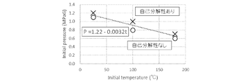
- FIG. 1 is a graph showing the conditions of temperature (t) and pressure (gauge pressure) (p) at which difluoroethylene (HFO-1132 (E)) undergoes autolysis, and the straight line indicated by the dotted line indicates the presence or absence of autolysis. Indicates the boundary of.
- the region above the straight line is in a state of having autolysis, and the region below the straight line is a region having no autolysis. That is, when p is less than 1.22-0.0032t, difluoroethylene does not have autolysis.
- this straight line is also referred to as "self-decomposition boundary line”.
- the points indicated by ⁇ are the points evaluated as having no autolysis by the above method under the temperature condition and the pressure (gauge pressure) condition, and the points indicated by ⁇ . Is the point evaluated as having autolysis.
- the above formula was calculated based on these measured values. Before ignition, the mixing medium mixed at various ratios is sealed to a predetermined pressure, and then the platinum wire installed inside is not blown. After ignition, the energy of about 30 J is obtained by blowing the gold wire. Refers to the time when
- the component held in the first container for example, crude difluoroethylene obtained by a method such as dehydrofluoric acid of 1,1,2-trifluoroethane (HFC143) is distilled. , Purified difluoroethylene having a difluoroethylene content adjusted to a range of about 65 mol% to 100 mol% can be used.
- the component held in the first container may contain a compound other than difluoroethylene in a proportion of less than 35 mol% with respect to the total amount of the component held in the first container.
- Compounds other than difluoroethylene that may be contained in the component held in the first container include, for example, by-products produced during the production of difluoroethylene and saturated hydros contained in the component held in the second container. Included are at least one selected from fluorocarbons, unsaturated hydrofluorocarbons, unsaturated hydrochlorofluorocarbons and unsaturated chlorofluorocarbons.
- Difluoroethylene is stored in a state where its temperature (t) and pressure (p) are p [MPaG] ⁇ 1.22-0.0032t, so that stability during storage is ensured. If it can be stored in a state in which only the difluoroethylene liquid is present in a specific container, in that case, stable storage is possible without causing autolysis.
- FIG. 2 shows a graph showing the relationship between the temperature and pressure at which difluoroethylene becomes a liquid (vapor pressure curve), which is superimposed on the graph of FIG.
- the curve shown by the solid line is the vapor pressure curve
- difluoroethylene is a gas in the region on the right side of the vapor pressure curve
- difluoroethylene is a liquid in the region on the left side.
- the state in which only the difluoroethylene liquid is present as described above refers to the liquid region on the left side of the vapor pressure curve in FIG.
- difluoroethylene liquid when a difluoroethylene liquid is stored in a container, it is stored in a gas-liquid mixed state in which the difluoroethylene liquid and gas coexist.
- the temperature and pressure in the gas-liquid mixed state are indicated by the temperature and pressure on the vapor pressure curve, but difluoroethylene shows a stable state in the gas-liquid mixed state at a temperature of 180 ° C. or lower and below the self-decomposition boundary line. Area of. Specifically, it is a region below the intersection of the autolysis boundary lines (temperature 15 ° C., pressure 1.2 MPaG) in the vapor pressure curve.
- the "preservation suitable region" of difluoroethylene is used as a term indicating the shaded region in FIG. Even when the difluoroethylene liquid is stored in a container, if the part not filled with the liquid can be replaced with a gas other than difluoroethylene that does not affect the storage of difluoroethylene, for example, nitrogen. , Stable storage at the temperature and pressure of the liquid region on the left side of the vapor pressure curve in Fig. 2 is possible.
- ingredients held in the second container are at least one selected from saturated hydrofluorocarbons, unsaturated hydrofluorocarbons, unsaturated hydrochlorofluorocarbons and unsaturated chlorofluorocarbons. Is contained in a proportion of 35 mol% or more, and these are components having no self-degradability.
- At least one selected from saturated hydrofluorocarbons, unsaturated hydrofluorocarbons, unsaturated hydrochlorofluorocarbons and unsaturated chlorofluorocarbons contained in the components held in the second container includes the compounds exemplified above. The same applies to the preferred compounds and combinations thereof.
- the component retained in the second container may be a non-autolytic mixture containing difluoroethylene in a proportion of less than 65 mol%.
- the working medium targeted by the production method of the present invention that is, at least difluoroethylene
- Any composition may be used as long as a working medium containing 65 mol% or less can be obtained.
- the composition is such that the working medium having any of the above compositions (i) to (iii) can be obtained.
- the component held in the second container is preferably composed of HFO-1234yf and / or HFC-32.
- Process (A), Process (B) and Process (C) In the manufacturing method of the present disclosure, the component held in the first container is held in the first container, and the component held in the second container is held in the second container and prepared. Then, the component held in the first container and the component held in the second container are mixed by any one of step (A), step (B), or step (C). Will be.
- the pressure is a gauge pressure unless otherwise specified.
- the components held in the first container are supplied to the second container under the following conditions (A1) or (A2).
- the temperature (t1) of the component held in the first container at the time of supply is set to t1 ⁇ 15 ° C., and at least from the start of the supply to the end of the mixing, the second The relationship between the gauge pressure (P2) in the container and the gauge pressure (p1) of the component held in the first container at the time of supply is p1> P2, and the temperature in the second container ( T2) is maintained at T2 ⁇ 15 ° C.
- the temperature (t1) of the component held in the first container at the time of supply is 15 ° C ⁇ t1 ⁇ 180 ° C
- the gauge pressure (p1) is p1 [MPaG] ⁇
- the gauge pressure (P2) in the second container is set to p1> P2
- the temperature (T2) in the second container is maintained in the state of T2 ⁇ 180 ° C. and T2 ⁇ (1.22-p1) /0.0032.
- the temperature in the first container and the temperature in the second container are both maintained at less than 15 ° C. It is preferable that the component held in the first container is supplied to the second container in a liquid state of t1 ⁇ 15 ° C.
- the conditions specified in (A1) and (A2) below are the temperature (t1) and pressure of the component held in the first container when the component held in the first container is supplied to the second container. (P1) and at least the components held in the first container and the second container, which are carried out in the second container by the supply from the start of supply to the second container. Regarding the temperature (T2) and pressure (P2) in the second container until the mixing of the components held in the container is completed.
- the "during supply” temperature and pressure refer to the temperature and pressure at the time when the component held in a certain container enters the container, and unless otherwise specified, the temperature and pressure are when the supply is continuously performed. , It is kept in a constant state from the start to the end of supply.
- step (A) All of these conditions in step (A) are set based on the conditions that are stable when the content of difluoroethylene in the component held in the first container is 100 mol%. From this, in the step (A), the above condition is that the component held in the first container of any composition within the specified range and the component held in the second container of any composition are mixed to obtain any composition. It can be said that this is a condition for ensuring stability even when a working medium having a composition is produced.
- condition setting made based on the condition that the content of difluoroethylene in the component held in the first container is stable when the content of difluoroethylene is 100 mol% is also applied to the steps (B) and (C) described later. Therefore, it can be said that the stability can be ensured in the steps (B) and (C) as well as the step (A) above.
- the temperature (t1) of the component held in the first container at the time of supply is set to t1 ⁇ 15 ° C., and at least from the start of the supply to the end of the mixing, the second The relationship between the gauge pressure (P2) in the container and the gauge pressure (p1) of the component held in the first container at the time of supply is p1> P2, and the temperature in the second container ( T2) is maintained at T2 ⁇ 15 ° C.
- the temperature (t1) of the component held in the first container at the time of supply is 15 ° C ⁇ t1 ⁇ 180 ° C
- the gauge pressure (p1) is p1 [MPaG] ⁇
- the gauge pressure (P2) in the second container is set to p1> P2
- the temperature (T2) in the second container is maintained in the state of T2 ⁇ 180 ° C. and T2 ⁇ (1.22-p1) /0.0032.
- the common condition is the component held in the first container when the component held in the first container is supplied to the second container. It is a condition regarding the pressure that the relationship between the pressure (p1) and the pressure (P2) in the second container is p1> P2.
- This pressure condition is an essential condition for supplying the components held in the first container to the second container.
- (A1) and (A2) are held in the first container at the time of supply under the essential pressure condition of p1> P2 when supplying the components held in the first container to the second container. It shows the relationship between the temperature (t1) and pressure (p1) of the components and the temperature (T2) in the second container, respectively.
- the second container is the component held in the first container and the second container, which is carried out in the second container by the supply from at least the start of the supply of the component held in the first container.
- the temperature (T2) and pressure (P2) may be kept in the above-mentioned (A1) or (A2) states until the mixing of the components held in the container is completed.
- the working medium having a stable composition according to the embodiment of the present invention is obtained as a reservoir in the second container.
- the components held in the second container housed in the second container and the working medium according to the embodiment of the present disclosure are both autolyzed. Since it has no property, there is no particular point to pay attention to its handling from the viewpoint of autolysis.
- the end time of the above mixing is usually the time when the supply of the component held in the first container is stopped, as will be described later.
- the temperature (T1) and pressure (P1) in the first container holding the component held in the first container are always the content of difluoroethylene in the component held in the first container shown above.
- T1 and pressure (P1) in the first container holding the component held in the first container are always the content of difluoroethylene in the component held in the first container shown above.
- the supply pipe connecting the first container and the second container is connected. Is arranged, and the component held in the first container is supplied to the second container via the supply pipe.
- the supply pipe connecting the first container and the second container usually has a means for controlling ON / OFF of the supply of the components held in the first container and the supply amount per hour, and if necessary.
- Pressure adjusting means, and temperature adjusting means In step (A), a pressure adjusting means, typically a pump, provided in the supply pipe is usually used to achieve p1> P2, which is an essential condition of this step.
- the temperature (t1) and pressure (p1) of the components held in the first container at the time of supply are not necessarily in the first container held at the temperature (T1) and pressure (P1) in the first container. It does not match the temperature and pressure conditions of the retained components.
- FIG. 2 shows the temperature (t1) and pressure of the component held in the first container at the time of supply, which can be taken to stably supply the component held in the first container into the second container. The range of (p1) is shown in full.
- the temperature (t1) and pressure (p1) of the components held in the first container at the time of supply are referred to as the filled t1 ⁇ 15 ° C region (hereinafter referred to as “low temperature region”) under the condition (A1) in FIG. Within) or within the gas region (hereinafter referred to as "low pressure region”) where 15 ° C ⁇ t1 ⁇ 180 ° C and p1 [MPaG] ⁇ 1.22-0.0032t1 indicated by the lattice pattern under the condition (A2).
- the first by setting the temperature (T2) in the second container to the predetermined conditions, specifically, the conditions (A1) and (A2), respectively, under the pressure condition of p1> P2. It is possible to stably supply the components held in the container. At this time, it is preferable to adjust the supply amount per hour for supplying the components held in the first container to the second container.
- (A1) is a condition setting for supplying the component held in the first container in the low temperature region to the second container in the same temperature region in a lower pressure state, and if this condition is satisfied, the second The stability of the container can be ensured.
- the component held in the first container in the low pressure region has a lower pressure
- the temperature (T2) is 180 ° C. or lower
- the temperature (t1) of the component held in the first container is Even if the temperature inside the second container rises to (T2), it is a condition setting to supply to the second container in a state where the pressure (p1) is below the self-decomposition boundary line, and this condition can be satisfied. For example, the stability of the second container can be ensured.
- the component held in the first container in the first container is held as a liquid below 15 ° C.
- the components held in the first container are preferably stored in a state where gas and liquid coexist.
- the temperature and pressure of the first container are adjusted so that the temperature is preferably less than 15 ° C. and is on the vapor pressure curve of difluoroethylene.
- the first container at the time of supply is provided so as to have a low temperature region and a liquid region. Adjust the temperature (t1) and pressure (p1) of the retained components.
- the temperature condition in the second container is T2 ⁇ 15 ° C according to (1) above.
- the state of the component held in the second container is preferably liquid, and is held in the second container within the conditions where the second container is placed, that is, p1> P2 and T2 ⁇ 15 ° C. Select the conditions under which the components are liquid.
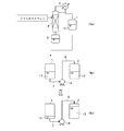
- FIG. 3 is a diagram schematically showing an example of step (A) when both the component held in the first container and the component held in the second container are liquids having a temperature of less than 15 ° C.
- FIG. 3 the difluoroethylene (liquid) 11 obtained in the state of being stored in the first container 1 is stored in the second container in which the component (liquid) 12 held in the second container prepared separately is stored.
- FIG. 3 (4b) is a diagram showing a state before the component 11 held in the first container is supplied to the second container 2
- FIG. 3 (4c) shows the state in which the first component 11 is the first. It is a figure which shows the state which was supplied to the container 2 of 2 and the working medium 13 was obtained.
- a canned solution or distillate obtained by a known method and purified by distillation is used as the second component. It may be stored in a container, or may be a component held in a second container in a commercially available container.
- the temperature (T1) in the first container 1 is less than 15 ° C
- the pressure (P1) is the condition that the component held in the first container becomes a liquid, specifically -50 ° C or more. It is adjusted to the pressure on the above vapor pressure curve below 15 ° C.
- the temperature and pressure of the components held in the first container in the first container 1 are the same as the temperature (T1) and pressure (P1) in the first container.
- the first container 1 has a discharge port
- the second container 2 has a supply port
- the component 11 held in the first container in the first container 1 passes through the supply pipe 7 and the supply pipe 8 from the discharge port of the first container 1 via the pump 14, and the second container 2 It moves to the supply port of the container and is supplied into the second container 2.
- the supply pipe 7 connects the discharge port of the first container 1 to the pump 14, and the supply pipe 8 connects the pump 14 to the second container 2 from the supply port.
- the temperature (T2) is less than 15 ° C.
- the pressure (P2) is held in the second container 2.
- the movement is usually performed by the self-pressure of the component held in the first container.
- the pressure (p1) and temperature (t1) at the time of supplying the components held in the first container supplied to the second container are the temperature (T1) and the pressure (T1) in the first container. Same as P1).
- the pump 14 When the pressure (P2) is higher than the pressure (P1), the pump 14 causes the supply pressure (p1) of the components held in the first container to be higher than the pressure (P2) in the second container 2. It is pressurized.
- the temperature (t1) of the component held in the first container after pressurization does not have to be the same as the temperature before pressurization (T1), but pressurizes within a range of holding less than 15 ° C. Will be done. That is, the component held in the first container is supplied into the second container as a liquid in the low temperature region.
- the temperature and pressure of the components held in the first container in the supply pipe 7 connecting the first container 1 and the pump 14 are the temperature (T1) of the first container 1. Same as pressure (P1).
- the temperature and pressure of the component held in the first container in the supply pipe 8 connecting the pump 14 and the second container 2 is the temperature and pressure of the component held in the first container at the time of supply (t1).
- pressure (p1), and the relationship of pressure is P1 ⁇ P2 ⁇ p1.
- the conditions for executing step (A) correspond to the case of (A1) above. Therefore, at least from the start of the supply of the component held in the first container to the end of mixing the component held in the first container and the component held in the second container, the second container 2 Keep the temperature (T2) below 15 ° C.
- step (A) when both the component held in the first container and the component held in the second container are liquids having a temperature of less than 15 ° C., as shown in FIG. 4, for example.
- FIG. 4 shows a second container held in the second container when the component held in the first container and the component held in the second container are both liquids having a temperature of less than 15 ° C. and the step (A) is performed. It is a figure which shows typically the operation of supplying the component held in the 1st container in a liquid state into the liquid of the component held in the container 2.
- the supply pipe 8 is arranged so as to connect the pump 14 and the supply port of the second container 2.
- FIG. 4 In the method shown in FIG. 4, one end of the supply pipe 8 is connected to the pump 14, and the component (liquid) 12 contained in the component (liquid) 12 held in the second container from the pump 14 through the supply port of the second container 2. It is arranged so that the other end reaches the. Other than that, there are no differences. Also in the method shown in FIG. 4, the step (A) described above is performed when both the component held in the first container and the component held in the second container are liquids having a temperature of less than 15 ° C. The conditions do not change.
- the advantage of supplying the component held in the first container in a liquid state into the liquid of the component held in the second container held in the second container is The purpose is to promote the mixing of the components held in the second container and the components held in the first container.
- step (B) is held in a second container under the following conditions (B1) and (B2) in a first container holding the components held in the first container. This is the process of supplying the ingredients.
- step (B) the components held in the second container are supplied to the first container under the following conditions (B1) and (B2).
- the temperature (T1) and the gauge pressure (P1) in the first container are set to T1 ⁇ 15 ° C. or 15 ° C. ⁇ at least from the start of the supply to the end of the mixing. Keep in the state of T1 ⁇ 180 ° C and P1 [MPaG] ⁇ 1.22-0.0032T1.
- the gauge pressure (p2) of the component held in the second container is p2> P1 at least at the time of supply.
- the temperature in the first container and the temperature in the second container are both maintained at less than 15 ° C. It is preferable that the component held in the second container is supplied to the first container in a liquid state of t2 ⁇ 15 ° C.
- the conditions of the above (B2) in the step (B) are the pressure (p2) of the component held in the second container and the pressure (p2) of the component held in the second container when the component held in the second container is supplied to the first container. It is a condition related to pressure that the relationship of pressure (P1) in the container is p2> P1. This pressure condition is an essential condition for supplying the components held in the second container to the first container.
- the condition (B1) above was held in the first container, which is carried out in the first container by this supply, at least from the start of the supply of the component held in the second container to the first container.
- the temperature (T1) and pressure (P1) in the first container are maintained in the low temperature region or the low pressure region shown in FIG. 3 above until the mixing of the components and the components held in the second container is completed. It is a condition.
- the end of the mixing is usually the time when the supply of the components held in the second container is stopped.
- the temperature (T1) and pressure (P1) in the first container holding the ingredients held in the first container are shown above until before the start of supply of the ingredients held in the second container.
- the temperature and pressure in the range of conditions that are stable even when the content of difluoroethylene in the component held in the first container is 100 mol%, preferably 180 ° C. or less and below the self-decomposition boundary line. It is held at temperature and pressure, more preferably at a temperature and pressure within a suitable storage area.
- the working medium having a stable composition according to the embodiment of the present invention is obtained as a reservoir in the first container. This working medium does not have autolysis, and therefore, after the mixing is completed, there is no particular point to pay attention to the handling of the first container from the viewpoint of autolysis.
- the temperature (T2) and pressure (P2) of the second container 2 are not particularly limited.
- the temperature and pressure of the components held in the second container in the second container 2 are the same as the temperature (T2) and the pressure (P2), but the second container 1 is supplied to the first container 1.
- the temperature (t2) and pressure (p2) of the components held in the container can be adjusted by, for example, the following means.
- a supply pipe connecting the second container and the first container is provided.
- the components disposed and held in the second container are supplied to the first container via the supply pipe.
- the supply pipe connecting the first container and the second container usually has a means for controlling ON / OFF of the supply of the components held in the second container and the supply amount per hour, and if necessary. It also has a pressure adjusting means and a temperature adjusting means.
- a pressure adjusting means typically a pump, provided in the supply pipe is usually used to achieve p2> P1, which is an essential condition of the step.
- step (B) from the start of supply of the components held in the second container to the end of the mixing, the temperature (T1) and pressure (P1) in the first container are measured in the low temperature region shown in FIG. In order to keep the temperature (T1) and pressure (P1) within the low pressure region, the temperature at the time of supply of the component held in the second container to be supplied to the first container so as to be within the range. Adjust (t2) and pressure (p2), as well as the hourly supply.
- the temperature (t1) and pressure (P1) in the first container are in the low temperature region
- the temperature (t2) and pressure (p2) at the time of supplying the components held in the second container are lowered.
- the temperature (t2) and pressure (p2) at the time of supplying the components held in the second container are in the low pressure region. For example, set to.
- more stable conditions include the condition that the pressure (p2) is in the low pressure region and t2 ⁇ (1.22-P1) /0.0032.
- both the components held in the first container and the components held in the second container are mixed in a liquid state. It is preferable to do so.
- the component held in the first container is held in the first container as a liquid below 15 ° C.
- the components held in the first container are preferably stored in a state where gas and liquid coexist.
- the first container is adjusted so that the temperature and pressure are preferably below 15 ° C. and on the vapor pressure curve of difluoroethylene before the components held in the second container are supplied. Will be done.
- both the component held in the first container and the component held in the second container can be mixed in a liquid state.
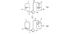
- FIG. 5 is a diagram schematically showing an example of step (B) when both the component held in the first container and the component held in the second container are liquids having a temperature of less than 15 ° C.
- the first container 1 in which the component 11 held in the first container is held and the second container 2 in which the component 12 held in the second container is held are prepared in the same manner as in the above step (A). it can.
- FIG. 5 is a diagram showing a state before the component 12 held in the second container is supplied to the first container 1
- FIG. 5 (6b) is a diagram showing the state before being supplied to the first container 1
- FIG. 5 (6b) is held in the second container. It is a figure which shows the state which the component 12 was supplied to the 1st container 1 and the working medium 13 was obtained.
- the temperature (T1) in the first container 1 is less than 15 ° C. as described above, and the pressure (P1) is such that the component held in the first container is a liquid.
- the pressure is adjusted to the pressure on the vapor pressure curve at -50 ° C or higher and lower than 15 ° C.
- the temperature and pressure of the components held in the first container in the first container 1 are the same as the temperature (T1) and pressure (P1) in the first container.
- the second container 2 has a discharge port
- the first container 1 has a supply port
- the component 12 held in the second container in the second container 2 passes through the supply pipe 9 and the supply pipe 10 from the discharge port of the second container 2 via the pump 14, and the first container 1 Moves to the supply port of the container 1 and is supplied into the first container 1.
- the supply pipe 9 connects the discharge port of the second container 2 to the pump 14, and the supply pipe 10 connects the pump 14 to the supply port of the first container 1.
- the temperature (T2) is less than 15 ° C.
- the pressure (P2) is held in the second container 2.
- the component held in the second container is liquid. It is set and held at the pressure to be in the state.
- the pressure (P1) in the first container 1 is lower than the pressure (P2) in the second container 2
- the movement is usually performed by the self-pressure of the components held in the second container.
- the pressure (p2) and temperature (t2) at the time of supplying the components held in the second container supplied to the first container are the temperature (T2) and the pressure (P2) in the second container. ) Is the same.
- the pressure (P1) when the pressure (P1) is higher than the pressure (P2), the pressure (p2) at the time of supplying the component held in the second container by the pump 14 is the pressure (P1) in the first container 1. It is pressurized to a higher state.
- the temperature (t2) of the component held in the second container after pressurization does not have to be the same as the temperature before pressurization (T2), but pressurizes within a range of holding less than 15 ° C. Will be done. That is, the component held in the second container is supplied into the first container as a liquid in the low temperature region.
- the temperature and pressure of the components held in the second container in the supply pipe 9 connecting the second container 2 and the pump 14 are the temperature (T2) and pressure (P2) of the second container 2. Is the same as.
- the temperature and pressure of the component held in the second container in the supply pipe 10 connecting the pump 14 and the first container 1 are the temperature and pressure of the component held in the second container at the time of supply (t2). )
- pressure (p2), and the relationship of pressure is P2 ⁇ P1 ⁇ p2.
- step (B) the conditions for executing step (B) are as described in (B1) and (B2) above. Therefore, at least from the start of the supply of the component held in the second container to the end of mixing the component held in the second container and the component held in the first container, the first container 1 Keep the temperature (T1) below 15 ° C.
- the first container held in the first container is used.
- a method of supplying the second component in a liquid state into the liquid of the retained component may be adopted.
- the advantage of supplying the component held in the second container in a liquid state into the liquid of the component held in the first container held in the first container is that the second container has an advantage. The purpose is to facilitate mixing of the retained components with the components retained in the first container.
- step (C) the temperature (T3) and gauge pressure (P3) in the third container are supplied to a third container prepared separately from the start of supply at least the following. Until the mixing is completed, the temperature is maintained at T3 ⁇ 15 ° C (low temperature region) or 15 ° C ⁇ T3 ⁇ 180 ° C and P3 [MPaG] ⁇ 1.22-0.0032T3 (low pressure region).
- the component held in the first container is supplied under the following conditions (C1) or (C2), and the component held in the second container is supplied at a gauge pressure (p2) at least at the time of supply. ) Is the process of supplying so that p2> P3.
- the conditions specified in (C1) and (C2) below are the temperature (t1) and pressure of the component held in the first container when the component held in the first container is supplied to the third container. (P1) and at least the components held in the first container and the second component held in the first container, which is carried out in the third container by the supply from the start of the supply to the third container. Regarding the temperature (T3) and pressure (P3) in the third container until the mixing of the components held in the container is completed.
- This condition is a condition setting when the second container of the conditions specified in (A1) and (A2) in the above step (A) is changed to the third container, and the temperature inside the second container ( It is the same except that T2) and pressure (P2) are replaced with the temperature (T3) and pressure (P3) in the third container.
- the temperature (T3) and the gauge pressure (P3) in the third container are supplied to the separately prepared third container at least from the start of the following supply to the end of the mixing. , T3 ⁇ 15 ° C, or 15 ° C ⁇ T3 ⁇ 180 ° C and P3 [MPaG] ⁇ 1.22-0.0032 T3.
- the component is supplied under the condition of (C2), and the component held in the second container is supplied so that the gauge pressure (p2) is p2> P3 at least at the time of the supply.
- the temperature (t1) of the component held in the first container at the time of supply is set to t1 ⁇ 15 ° C., and at least from the start of the supply to the end of the mixing, the third The relationship between the gauge pressure (P3) in the container and the gauge pressure (p1) of the component held in the first container at the time of supply is p1> P3, and the temperature in the third container ( T3) is maintained at T3 ⁇ 15 ° C.
- the temperature (t1) of the component held in the first container at the time of supply is 15 ° C ⁇ t1 ⁇ 180 ° C
- the gauge pressure (p1) is p1 [MPaG] ⁇
- the gauge pressure (P3) in the third container is set to p1> P3
- the temperature (T3) in the third container is maintained in the state of T3 ⁇ 180 ° C. and T3 ⁇ (1.22-p1) /0.0032.
- the temperature in the first container, the temperature in the second container and the temperature in the third container are both set.
- the common condition is the component held in the first container when the component held in the first container is supplied to the third container. It is a condition regarding the pressure that the relationship between the pressure of (p1) and the pressure in the third container (P3) is p1> P3.
- This pressure condition is an essential condition for supplying the components held in the first container to the third container.
- (C1) and (C2) are held in the first container at the time of supply under the essential pressure condition of p1> P3 when the components held in the first container are supplied to the third container. It shows the relationship between the temperature (t1) and pressure (p1) of the added components and the temperature (T3) in the third container, respectively.
- the third container is the first container, which is carried out in the third container by this supply from the start of supply of the component held in at least the first container and the component held in the second container. If the temperature (T3) and pressure (P3) are set to the above (C1) or (C2) states until the mixing of the component held in the container of 1 and the component held in the second container is completed. good.
- the working medium having a stable composition according to the embodiment of the present disclosure is obtained as a reservoir in the third container.
- the end time of the above mixing is usually the time when the supply of the component held in the first container is stopped, as will be described later.
- the temperature (T1) and pressure (P1) in the first container holding the component held in the first container are always the content of difluoroethylene in the component held in the first container shown above.
- T1 and pressure (P1) in the first container holding the component held in the first container are always the content of difluoroethylene in the component held in the first container shown above.
- a supply pipe connecting the first container and the third container is arranged and held in the first container.
- the ingredients are supplied to the third container through this supply pipe.
- the supply pipe connecting the first container and the third container usually has a means for controlling ON / OFF of the supply of the components held in the first container and the supply amount per hour, and if necessary. It also has a pressure adjusting means and a temperature adjusting means.
- a pressure adjusting means typically a pump, provided in the supply pipe is usually used to achieve p1> P3, which is an essential condition of this step.
- the temperature (t1) and pressure (p1) of the components held in the first container at the time of supply are not necessarily the temperature (T1) and pressure (P1) held in the first container. It does not match the temperature and pressure conditions of the components held in one container. If the temperature (t1) and pressure (p1) range of the components held in the first container at the time of supply to the third container is within the low temperature region or the low pressure region, the pressure condition of p1> P2 described above. By setting the temperature (T3) in the third container to the predetermined conditions, specifically, the conditions (C1) and (C2), respectively, the supply of the components held in the first container is stabilized. It can be carried out.
- the temperature (T2) and pressure (P2) of the second container 2 are not particularly limited.
- the temperature and pressure of the components held in the second container in the second container 2 are the same as the temperature (T2) and the pressure (P2), but the second container 3 is supplied to the third container 3.
- the temperature (t2) and pressure (p2) of the components held in the container can be adjusted by, for example, the following means.
- a supply pipe connecting the second container and the third container is arranged and held in the second container.
- the ingredients are supplied to the third container via the supply pipe.
- the supply pipe connecting the second container and the third container usually has means for controlling the supply ON / OFF of the second component and the supply amount per hour, and if necessary, the pressure adjusting means. , Has temperature adjusting means.
- step (C) in order to achieve p2> P3, which is an essential condition of this step, a pressure adjusting means arranged in a supply pipe, typically a pump, is usually used.
- step (C) from the start of supplying the component held in the first container and the component held in the second container to the third container to the end of mixing in the third container, the first step.
- the temperature (t1) and pressure (p1) at the time of supplying the components held in the first container. Is the condition of (C1) or (C2), and the component held in the second container supplied to the third container so that the temperature (T3) and the pressure (P3) are within the range.
- the temperature (t3) and pressure (P3) in the third container are in the low temperature region
- the temperature (t2) and pressure (p2) at the time of supplying the components held in the second container are lowered.
- the temperature (t2) and pressure (p2) at the time of supplying the second component may be set in the low pressure region.
- More stable than this case is the condition that the pressure (p2) is in the low pressure region and t2 ⁇ (1.22-P3) /0.0032.
- the first component is held as a liquid below 15 ° C. in the first container.
- the components held in the first container are preferably stored in a state where gas and liquid coexist. Therefore, the first vessel is adjusted so that the temperature (T1) and pressure (P1) are preferably less than 15 ° C. and on the vapor pressure curve of difluoroethylene.
- the components retained in the second container are retained in the second container as a liquid below 15 ° C.
- the components prepared in this manner both held in the first container as a liquid below 15 ° C. and the components held in the second container, are described above for the components held in the first container.
- a liquid state of less than 15 ° C so as to meet the condition of (C1), while ensuring the relationship of p2> P3 for the components held in the second container, in a liquid state of less than 15 ° C.
- It is supplied to a third container held in a cold region.
- the components held in the first container and the components held in the second container are both mixed in a liquid state in the third container. Can be done.
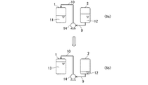
- FIG. 6 shows the components held in the first container in the third container and the components held in the first container when both the components held in the first container and the components held in the second container are liquids below 15 ° C. It is a figure which shows typically an example of the step (C) of supplying the component held in the 2nd container together.
- FIG. 6 (7a) is a diagram showing a state before the component 11 held in the first container and the component 12 held in the second container are supplied to the third container 3.
- FIG. (7b) is a diagram showing a state in which the component 11 held in the first container and the component 12 held in the second container are supplied to the third container 3 to obtain the working medium 13.
- the first container 1 in which the component 11 held in the first container shown in FIG. 6 (7a) is held and the second container 2 in which the component 12 held in the second container is held are described in the above ( A) Can be prepared in the same way as the process.
- FIG. 6 the component (liquid) 11 held in the first container held in the first container 1 and the component (liquid) held in the second container held in the second container 2 are shown.
- the operation in which 12 is supplied together with the third container 3 is shown.
- the first container 1 and the second container 2 have one discharge port
- the third container 3 has two supply ports.
- the discharge ports of the first container 1 and the second container 2 are supply pipes 7 and 8 through which gas or liquid can flow to the two supply ports of the third container 3 via pumps 15 and 16, respectively. It is connected by supply pipes 9 and 10.
- the component 11 held in the first container in the first container 1 and the component 12 held in the second container in the second container 2 are the discharge port and the first container, respectively, which the first container 1 has. From the discharge port of the container 2 of 2, the inside of the supply pipes 7, 8 and the supply pipes 9 and 10 is moved to the supply port of the third container 3 via the pump 15 and the pump 16, respectively, and the third container is used. Supplied within 3.
- the inside of the third container 3 is formed by supplying the component 11 held in the first container and the component 12 held in the second container into the third container 3 together.
- the component 11 held in the first container and the component 12 held in the second container are mixed to obtain the working medium 13.
- the supply of the component 11 held in the first container and the supply of the component 12 held in the second container are usually performed at the same time. In that case, the supply amount of the component 11 held in the first container and the supply amount of the component 12 held in the second container to the third container 3 at any time in the third container together with these supplies. It is preferable that the composition of the stored matter is adjusted so as to be the composition of the target working medium.
- a means for continuously measuring the composition of the reservoir in the third container 3 is provided, and the component held in the first container 11 until the required amount of the working medium having the desired composition is produced.
- the supply amount of the component 12 and the supply amount of the component 12 held in the second container may be adjusted at any time.
- the conditions for executing step (C) correspond to the case of (C1) above. Therefore, at least from the start of the supply of the component held in the first container to the end of mixing the component held in the first container and the component held in the second container, the third Keep the temperature (T3) of container 3 below 15 ° C.
- a predetermined amount of the component 11 held in the first container is previously supplied to the third container 3, and then the component 12 held in the second container is located.
- a fixed amount may be supplied to the third container 3, and a predetermined amount of the component 12 held in the second container is previously supplied to the third container 3 and then held in the first container.
- a predetermined amount of the component 11 may be supplied to the third container 3.
- the target medium-producing medium can be stably produced by handling the component held in the first container and the component held in the second container under the same conditions as in step (B) above. it can. Further, in the latter case, the target medium-forming medium can be stably produced by handling the component held in the first container and the component held in the second container under the same conditions as in the above step (A).
- the components held in the second container are supplied to the third container in the step (C), they are held in each container from a plurality of second containers. Ingredients held in a plurality of identical or different second containers may be supplied. At this time, the components held in the first container and the components held in the plurality of second containers may be supplied to the third container at the same time in accordance with the conditions of the manufacturing method of the present disclosure. , If necessary, either supply may be performed first.
- the first container by supplying the component held in the above-mentioned predetermined container into the first container, the second container, or the third container.
- the component held in the container and the component held in the second container are continuously changed in composition and mixed to finally obtain a working medium.
- the component held in the first container and the component held in the second container are unevenly present depending on the position.
- the components held in a predetermined container are supplied into the container while appropriately adjusting the discharge pressure of the pump, and the components held in the first container and the components held in the second container are mixed in the container.
- the tip of the supply pipe is set to the inside of the first container and the second container.
- the medium produced by the production method of the present disclosure is a medium confirmed to have no autolysis under temperature and pressure conditions when used as an operating medium.
- the working medium produced in the first container, the second container, or the third container is filled in a subdivided container or the like, it is not necessary to strictly control the temperature and pressure conditions. For example, when transferring from a manufactured container to a subdivision container, it is stable even if the transfer is performed at the pressure and temperature in the region above the autolysis boundary line of difluoroethylene.
- the preferred conditions for subdivision are -40 ° C to 15 ° C, preferably -20 ° C to 0 ° C for the working medium produced in the first container, the second container, or the third container. It is to hold and transfer the discharge side pressure of the pump through the pump to the subdivision container at a gauge pressure of 0.1 MPaG to 3.0 MPaG, preferably 0.3 MPaG to 2.0 MPaG at a gauge pressure.
- the method for producing the working medium of the present invention is not limited to the above embodiment.
- the configuration can be appropriately changed as long as it does not contradict the gist of the present invention and as necessary.
- the first container is filled with 18 kg of HFO-1132 (E) cooled to 10 ° C.
- the pressure in the first container at this time is 1.0 MPaG.
- the second container is filled with 12 kg of HFC-32 cooled to -30 ° C.
- the pressure in the second container at this time is 0.17 MPaG.
- the temperature of the supply pipe is 10 ° C and the pressure is 1.0 MPaG.
- the composition of HFO-1132 (E) in the first container and the composition in the second container are always in a state where the autolysis reaction does not occur.
- the first container is filled with 18 kg of HFO-1132 (E) cooled to -30 ° C.
- the pressure in the first container at this time is 0.18 MPaG.
- the second container is filled with 12 kg of HFC-32 cooled to 10 ° C.
- the pressure in the second container at this time is 1.0 MPaG.
- the temperature of the supply pipe is 10 ° C and the pressure is 1.0 MPaG.
- the composition of the first container is always in a state where an autolysis reaction does not occur.
- the second container is filled with 12 kg of HFC-32 cooled to -30 ° C.
- the pressure in the second container at this time is 0.17 MPaG.
- Another first container is filled with 18 kg of HFO-1132 (E) cooled to 10 ° C.
- the pressure in the first container at this time is 1.0 MPaG.
- the temperature of the first container was changed to 10 ° C.
- a third container is filled with 18 kg of cooled HFO-1132 (E) under the conditions of a supply pipe temperature of 10 ° C. and a pressure of 1.0 MPaG.
- the composition of HFO-1132 (E) in the first container and the composition in the third container are always in a state where an autolysis reaction does not occur.
- the working medium obtained by the method for manufacturing the working medium of the present disclosure can be handled with high stability, and freezing / refrigerating equipment (built-in showcase, separate showcase, commercial freezer / refrigerator, vending machine).
- Refrigerants for ice machines, etc. refrigerants for air conditioners (room air conditioners, package air conditioners for stores, package air conditioners for buildings, package air conditioners for equipment, gas engine heat pumps, air conditioners for trains, air conditioners for automobiles, etc.), power generation systems ( It is useful as a working fluid for waste heat recovery power generation, etc.), a working medium for heat transport devices (heat pipes, etc.), and a medium for secondary air conditioners.
Landscapes
- Chemical & Material Sciences (AREA)
- Organic Chemistry (AREA)
- Engineering & Computer Science (AREA)
- Physics & Mathematics (AREA)
- Chemical Kinetics & Catalysis (AREA)
- Combustion & Propulsion (AREA)
- Thermal Sciences (AREA)
- Materials Engineering (AREA)
- Organic Low-Molecular-Weight Compounds And Preparation Thereof (AREA)
Abstract
ジフルオロエチレンが自己分解性を有しない、ジフルオロエチレンを含有する作動媒体の製造方法を提供する。 ジフルオロエチレンを含有する作動媒体の製造方法。
Description
本開示は、ジフルオロエチレンを含有する作動媒体の製造方法に関する。
特許文献1には、トリフルオロエチレンを含有する作動媒体の製造方法が開示されている。
ジフルオロエチレンが自己分解性を有しない、ジフルオロエチレンを含有する作動媒体の製造方法を提供することを課題とする。
項1.
ジフルオロエチレンを含有する作動媒体の製造方法であって、
第1の容器内に保持された、ジフルオロエチレンを、65モル%を超える割合で含有する第1の成分と、
第2の容器内に保持された、自己分解性を有しない第2の成分とを、
下記(A)、(B)又は(C)の工程により混合することを含み、
ジフルオロエチレンを、全量に対して、65モル%以下の割合で含有する作動媒体を製造する、方法。
ジフルオロエチレンを含有する作動媒体の製造方法であって、
第1の容器内に保持された、ジフルオロエチレンを、65モル%を超える割合で含有する第1の成分と、
第2の容器内に保持された、自己分解性を有しない第2の成分とを、
下記(A)、(B)又は(C)の工程により混合することを含み、
ジフルオロエチレンを、全量に対して、65モル%以下の割合で含有する作動媒体を製造する、方法。
(A)工程
下記(A1)又は(A2)の条件において、前記第2の容器に、第1の容器に保持された成分を供給する。
下記(A1)又は(A2)の条件において、前記第2の容器に、第1の容器に保持された成分を供給する。
(A1)条件
前記供給時における前記第1の容器に保持された成分の温度(t1)をt1<15℃とし、少なくとも前記供給の開始から前記混合が終了するまでの間、前記第2の容器内のゲージ圧力(P2)と前記供給時における前記第1の容器に保持された成分のゲージ圧力(p1)との関係をp1>P2とすると共に、前記第2の容器内の温度(T2)を、T2<15℃の状態に保持する。
前記供給時における前記第1の容器に保持された成分の温度(t1)をt1<15℃とし、少なくとも前記供給の開始から前記混合が終了するまでの間、前記第2の容器内のゲージ圧力(P2)と前記供給時における前記第1の容器に保持された成分のゲージ圧力(p1)との関係をp1>P2とすると共に、前記第2の容器内の温度(T2)を、T2<15℃の状態に保持する。
(A2)条件
前記供給時における前記第1の容器に保持された成分を、その温度(t1)が15℃≦t1≦180℃であり、そのゲージ圧力(p1)がp1[MPaG]<1.22-0.0032t1である気体の状態とし、少なくとも前記供給の開始から前記混合が終了するまでの間、前記第2の容器内のゲージ圧力(P2)と前記第1の容器に保持された成分のゲージ圧力(p1)との関係をp1>P2とすると共に、前記第2の容器内の温度(T2)を、T2≦180℃且つT2<(1.22-p1)/0.0032の状態に保持する。
前記供給時における前記第1の容器に保持された成分を、その温度(t1)が15℃≦t1≦180℃であり、そのゲージ圧力(p1)がp1[MPaG]<1.22-0.0032t1である気体の状態とし、少なくとも前記供給の開始から前記混合が終了するまでの間、前記第2の容器内のゲージ圧力(P2)と前記第1の容器に保持された成分のゲージ圧力(p1)との関係をp1>P2とすると共に、前記第2の容器内の温度(T2)を、T2≦180℃且つT2<(1.22-p1)/0.0032の状態に保持する。
(B)工程
下記(B1)及び(B2)の条件において、前記第1の容器に、第2の容器に保持された成分を供給する。
下記(B1)及び(B2)の条件において、前記第1の容器に、第2の容器に保持された成分を供給する。
(B1)条件
前記第1の容器内の温度(T1)及びゲージ圧力(P1)を、少なくとも前記供給の開始から前記混合が終了するまで、T1<15℃の状態、又は、15℃≦T1≦180℃且つP1[MPaG]<1.22-0.0032T1の状態に保持する。
前記第1の容器内の温度(T1)及びゲージ圧力(P1)を、少なくとも前記供給の開始から前記混合が終了するまで、T1<15℃の状態、又は、15℃≦T1≦180℃且つP1[MPaG]<1.22-0.0032T1の状態に保持する。
(B2)条件
前記第2の容器に保持された成分は、少なくとも前記供給時において、そのゲージ圧力(p2)がp2>P1である。
前記第2の容器に保持された成分は、少なくとも前記供給時において、そのゲージ圧力(p2)がp2>P1である。
(C)工程
別に準備された第3の容器に、前記第3の容器内の温度(T3)及びゲージ圧力(P3)を、少なくとも以下の供給の開始から前記混合が終了するまでの間、T3<15℃の状態、又は、15℃≦T3≦180℃且つP3[MPaG]<1.22-0.0032T3の状態に保持しながら、 前記第1の容器に保持された成分を、下記(C1)又は(C2)の条件で供給し、
前記第2の容器に保持された成分を、少なくともその供給時において、そのゲージ圧力(p2)がp2>P3となるように供給する。
別に準備された第3の容器に、前記第3の容器内の温度(T3)及びゲージ圧力(P3)を、少なくとも以下の供給の開始から前記混合が終了するまでの間、T3<15℃の状態、又は、15℃≦T3≦180℃且つP3[MPaG]<1.22-0.0032T3の状態に保持しながら、 前記第1の容器に保持された成分を、下記(C1)又は(C2)の条件で供給し、
前記第2の容器に保持された成分を、少なくともその供給時において、そのゲージ圧力(p2)がp2>P3となるように供給する。
(C1)条件
前記供給時における前記第1の容器に保持された成分の温度(t1)をt1<15℃とし、少なくとも前記供給の開始から前記混合が終了するまでの間、前記第3の容器内のゲージ圧力(P3)と前記供給時における前記第1の容器に保持された成分のゲージ圧力(p1)との関係をp1>P3とすると共に、前記第3の容器内の温度(T3)を、T3<15℃の状態に保持する。
前記供給時における前記第1の容器に保持された成分の温度(t1)をt1<15℃とし、少なくとも前記供給の開始から前記混合が終了するまでの間、前記第3の容器内のゲージ圧力(P3)と前記供給時における前記第1の容器に保持された成分のゲージ圧力(p1)との関係をp1>P3とすると共に、前記第3の容器内の温度(T3)を、T3<15℃の状態に保持する。
(C2)条件
前記供給時における前記第1の容器に保持された成分を、その温度(t1)が15℃≦t1≦180℃であり、そのゲージ圧力(p1)がp1[MPaG]<1.22-0.0032t1である気体の状態とし、少なくとも前記供給の開始から前記混合が終了するまでの間、前記第3の容器内のゲージ圧力(P3)と前記第1の容器に保持された成分のゲージ圧力(p1)との関係をp1>P3とすると共に、前記第3の容器内の温度(T3)をT3≦180℃且つT3<(1.22-p1)/0.0032の状態に保持する。
前記供給時における前記第1の容器に保持された成分を、その温度(t1)が15℃≦t1≦180℃であり、そのゲージ圧力(p1)がp1[MPaG]<1.22-0.0032t1である気体の状態とし、少なくとも前記供給の開始から前記混合が終了するまでの間、前記第3の容器内のゲージ圧力(P3)と前記第1の容器に保持された成分のゲージ圧力(p1)との関係をp1>P3とすると共に、前記第3の容器内の温度(T3)をT3≦180℃且つT3<(1.22-p1)/0.0032の状態に保持する。
項2.
前記ジフルオロエチレンは、1,1-ジフルオロエチレン(HFO-1132a)、シス-1,2-ジフルオロエチレン(HFO-1132(Z))、及びトランス-1,2-ジフルオロエチレン(HFO-1132(E))からなる群から選ばれる少なくとも1種である、
前記項1に記載の作動媒体の製造方法。
前記ジフルオロエチレンは、1,1-ジフルオロエチレン(HFO-1132a)、シス-1,2-ジフルオロエチレン(HFO-1132(Z))、及びトランス-1,2-ジフルオロエチレン(HFO-1132(E))からなる群から選ばれる少なくとも1種である、
前記項1に記載の作動媒体の製造方法。
項3.
前記第2の容器に保持された成分は、飽和ヒドロフルオロカーボン、不飽和ヒドロフルオロカーボン、不飽和ヒドロクロロフルオロカーボン、及び不飽和クロロフルオロカーボンからなる群から選ばれる少なくとも1種である、
前記項1又は2に記載の作動媒体の製造方法。
前記第2の容器に保持された成分は、飽和ヒドロフルオロカーボン、不飽和ヒドロフルオロカーボン、不飽和ヒドロクロロフルオロカーボン、及び不飽和クロロフルオロカーボンからなる群から選ばれる少なくとも1種である、
前記項1又は2に記載の作動媒体の製造方法。
項4.
前記第2の容器に保持された成分は、前記自己分解性を有しない成分を35モル%以上の割合で含有する、
前記項3に記載の作動媒体の製造方法。
前記第2の容器に保持された成分は、前記自己分解性を有しない成分を35モル%以上の割合で含有する、
前記項3に記載の作動媒体の製造方法。
項5.
前記第2の容器に保持された成分は、2,3,3,3-テトラフルオロプロペン及び/又はジフルオロメタンを含む
前記項1~4のいずれか1項に記載の作動媒体の製造方法。
前記第2の容器に保持された成分は、2,3,3,3-テトラフルオロプロペン及び/又はジフルオロメタンを含む
前記項1~4のいずれか1項に記載の作動媒体の製造方法。
項6.
前記第1の容器に保持された成分と前記第2の容器に保持された成分とを混合して得られる作動媒体は、ジフルオロエチレン及び2,3,3,3-テトラフルオロプロペンを含む作動媒体であって、
作動媒体全量に対して、ジフルオロエチレン及び2,3,3,3-テトラフルオロプロペンの合計量の割合は65モル%~100モル%であり、
ジフルオロエチレン及び2,3,3,3-テトラフルオロプロペンの合計量に対して、ジフルオロエチレンの割合は1モル%~65モル%である、
前記項1~5のいずれか1項に記載の作動媒体の製造方法。
前記第1の容器に保持された成分と前記第2の容器に保持された成分とを混合して得られる作動媒体は、ジフルオロエチレン及び2,3,3,3-テトラフルオロプロペンを含む作動媒体であって、
作動媒体全量に対して、ジフルオロエチレン及び2,3,3,3-テトラフルオロプロペンの合計量の割合は65モル%~100モル%であり、
ジフルオロエチレン及び2,3,3,3-テトラフルオロプロペンの合計量に対して、ジフルオロエチレンの割合は1モル%~65モル%である、
前記項1~5のいずれか1項に記載の作動媒体の製造方法。
項7.
前記第1の容器に保持された成分と前記第2の容器に保持された成分とを混合して得られる作動媒体は、ジフルオロエチレン及びジフルオロメタンを含む作動媒体であって、
作動媒体全量に対して、ジフルオロエチレン及びジフルオロメタンの合計量の割合は65モル%~100モル%であり、
ジフルオロエチレン及びジフルオロメタンの合計量に対して、ジフルオロエチレンの割合は1モル%~65モル%である、
前記項1~5のいずれか1項に記載の作動媒体の製造方法。
前記第1の容器に保持された成分と前記第2の容器に保持された成分とを混合して得られる作動媒体は、ジフルオロエチレン及びジフルオロメタンを含む作動媒体であって、
作動媒体全量に対して、ジフルオロエチレン及びジフルオロメタンの合計量の割合は65モル%~100モル%であり、
ジフルオロエチレン及びジフルオロメタンの合計量に対して、ジフルオロエチレンの割合は1モル%~65モル%である、
前記項1~5のいずれか1項に記載の作動媒体の製造方法。
項8.
前記第1の容器に保持された成分と前記第2の容器に保持された成分とを混合して得られる作動媒体は、ジフルオロエチレン、2,3,3,3-テトラフルオロプロペン及びジフルオロメタンを含む作動媒体であって、
作動媒体全量に対して、ジフルオロエチレン、2,3,3,3-テトラフルオロプロペン及びジフルオロメタンの合計量の割合は65モル%~100モル%であり、
ジフルオロエチレン、2,3,3,3-テトラフルオロプロペン及びジフルオロメタンの合計量に対して、ジフルオロエチレンの割合は1モル%~65モル%であり、2,3,3,3-テトラフルオロプロペンの割合は98モル%以下であり、且つ、ジフルオロメタンの割合は98モル%以下である、
前記項1~5のいずれか1項に記載の作動媒体の製造方法。
項9.
前記第1の容器に保持された成分は、ジフルオロエチレンからなる、
前記項1~8のいずれか1項に記載の作動媒体の製造方法。
前記第1の容器に保持された成分は、ジフルオロエチレンからなる、
前記項1~8のいずれか1項に記載の作動媒体の製造方法。
項10.
前記第2の容器に保持された成分は、2,3,3,3-テトラフルオロプロペン及びジフルオロメタンの混合物からなる、
前記項8に記載の作動媒体の製造方法。
前記第2の容器に保持された成分は、2,3,3,3-テトラフルオロプロペン及びジフルオロメタンの混合物からなる、
前記項8に記載の作動媒体の製造方法。
項11.
前記第2の容器に保持された成分は、トランス-1,3,3,3-テトラフルオロプロペンからなる、
前記項1~4のいずれか1項に記載の作動媒体の製造方法。
前記第2の容器に保持された成分は、トランス-1,3,3,3-テトラフルオロプロペンからなる、
前記項1~4のいずれか1項に記載の作動媒体の製造方法。
項12.
前記第2の容器に保持された成分は、トランス-1,3,3,3-テトラフルオロプロペン及びジフルオロメタンの混合物からなる、
前記項1~4のいずれか1項に記載の作動媒体の製造方法。
前記第2の容器に保持された成分は、トランス-1,3,3,3-テトラフルオロプロペン及びジフルオロメタンの混合物からなる、
前記項1~4のいずれか1項に記載の作動媒体の製造方法。
項13.
前記(A)工程において、前記第1の容器内の温度及び前記第2の容器内の温度は、共に15℃未満に保持され、前記第1の容器に保持された成分をt1<15℃の液体の状態で前記第2の容器に供給する、
前記項1~4のいずれか1項に記載の作動媒体の製造方法。
前記(A)工程において、前記第1の容器内の温度及び前記第2の容器内の温度は、共に15℃未満に保持され、前記第1の容器に保持された成分をt1<15℃の液体の状態で前記第2の容器に供給する、
前記項1~4のいずれか1項に記載の作動媒体の製造方法。
項14.
前記(B)工程において、前記第1の容器内の温度及び前記第2の容器内の温度は、共に15℃未満に保持され、前記第2の容器に保持された成分をt2<15℃の液体の状態で前記第1の容器に供給する、
前記項1~4のいずれか1項に記載の作動媒体の製造方法。
前記(B)工程において、前記第1の容器内の温度及び前記第2の容器内の温度は、共に15℃未満に保持され、前記第2の容器に保持された成分をt2<15℃の液体の状態で前記第1の容器に供給する、
前記項1~4のいずれか1項に記載の作動媒体の製造方法。
項15.
前記(C)工程において、前記第1の容器内の温度、前記第2の容器内の温度及び第3の容器内の温度は、共に15℃未満に保持され、前記第1の容器に保持された成分をt1<15℃の液体の状態で、且つ前記第2の容器に保持された成分をt2<15℃の液体の状態で、夫々前記第3の容器に供給する、
前記項1~4のいずれか1項に記載の作動媒体の製造方法。
前記(C)工程において、前記第1の容器内の温度、前記第2の容器内の温度及び第3の容器内の温度は、共に15℃未満に保持され、前記第1の容器に保持された成分をt1<15℃の液体の状態で、且つ前記第2の容器に保持された成分をt2<15℃の液体の状態で、夫々前記第3の容器に供給する、
前記項1~4のいずれか1項に記載の作動媒体の製造方法。
本開示によれば、ジフルオロエチレンが自己分解性を有しない、ジフルオロエチレンを含有する作動媒体を製造することができる。
本開示によれば、ジフルオロエチレンが不均化反応を生じない、ジフルオロエチレンを含有する作動媒体を、安全に、製造することができる。
本開示は、地球温暖化への影響が少なく、サイクル性能に優れるジフルオロエチレンを含有しながら、通常の操作により安定性に優れる作動媒体を、安定に且つ効率良く製造する方法を提供することを目的とする。
本発明者は、ジフルオロエチレンの自己分解性について、ジフルオロエチレンを含む組成物において、組成物全量に対するジフルオロエチレンの含有量を65モル%以下とすれば、作動媒体として使用する場合の温度や圧力条件下で自己分解性を有しないことを見出した。
本開示は以下の態様を含む。
本開示のジフルオロエチレンを含有する作動媒体の製造方法は、
第1の容器内に保持された、ジフルオロエチレンを、65モル%を超える割合で含有する第1の容器に保持された成分と、
第2の容器内に保持された、自己分解性を有しない第2の容器に保持された成分とを、 次の(A)、(B)又は(C)の工程により混合することを含み、
ジフルオロエチレンを、全量に対して、65モル%以下の割合で含有する作動媒体を製造する、方法である。
第1の容器内に保持された、ジフルオロエチレンを、65モル%を超える割合で含有する第1の容器に保持された成分と、
第2の容器内に保持された、自己分解性を有しない第2の容器に保持された成分とを、 次の(A)、(B)又は(C)の工程により混合することを含み、
ジフルオロエチレンを、全量に対して、65モル%以下の割合で含有する作動媒体を製造する、方法である。
(A)工程では、次の(A1)又は(A2)の条件において、前記第2の容器に、第1の容器に保持された成分を供給する。
(A1)条件では、前記供給時における前記第1の容器に保持された成分の温度(t1)をt1<15℃とし、少なくとも前記供給の開始から前記混合が終了するまでの間、前記第2の容器内のゲージ圧力(P2)と前記供給時における前記第1の容器に保持された成分のゲージ圧力(p1)との関係をp1>P2とすると共に、前記第2の容器内の温度(T2)を、T2<15℃の状態に保持する。
(A2)条件では、前記供給時における前記第1の容器に保持された成分を、その温度(t1)が15℃≦t1≦180℃であり、そのゲージ圧力(p1)がp1[MPaG]<1.22-0.0032t1である気体の状態とし、少なくとも前記供給の開始から前記混合が終了するまでの間、前記第2の容器内のゲージ圧力(P2)と前記第1の容器に保持された成分のゲージ圧力(p1)との関係をp1>P2とすると共に、前記第2の容器内の温度(T2)を、T2≦180℃且つT2<(1.22-p1)/0.0032の状態に保持する。
(B)工程では、次の(B1)及び(B2)の条件において、前記第1の容器に、第2の容器に保持された成分を供給する。
(B1)条件では、前記第1の容器内の温度(T1)及びゲージ圧力(P1)を、少なくとも前記供給の開始から前記混合が終了するまで、T1<15℃の状態、又は、15℃≦T1≦180℃且つP1[MPa]<1.22-0.0032T1の状態に保持する。
(B2)条件では、前記第2の容器に保持された成分は、少なくとも前記供給時において、そのゲージ圧力(p2)がp2>P1である。
(C)工程では、別に準備された第3の容器に、前記第3の容器内の温度(T3)及びゲージ圧力(P3)を、少なくとも以下の供給の開始から前記混合が終了するまでの間、T3<15℃の状態、又は、15℃≦T3≦180℃且つP3[MPa]<1.22-0.0032T3の状態に保持しながら、前記第1の容器に保持された成分を、次の(C1)又は(C2)の条件で供給し、前記第2の容器に保持された成分を、少なくともその供給時において、そのゲージ圧力(p2)がp2>P3となるように供給する。
(C1)条件では、前記供給時における前記第1の容器に保持された成分の温度(t1)をt1<15℃とし、少なくとも前記供給の開始から前記混合が終了するまでの間、前記第3の容器内のゲージ圧力(P3)と前記供給時における前記第1の容器に保持された成分のゲージ圧力(p1)との関係をp1>P3とすると共に、前記第3の容器内の温度(T3)を、T3<15℃の状態に保持する。
(C2)条件では、前記供給時における前記第1の容器に保持された成分を、その温度(t1)が15℃≦t1≦180℃であり、そのゲージ圧力(p1)がp1[MPa]<1.22-0.0032t1である気体の状態とし、少なくとも前記供給の開始から前記混合が終了するまでの間、前記第3の容器内のゲージ圧力(P3)と前記第1の容器に保持された成分のゲージ圧力(p1)との関係をp1>P3とすると共に、前記第3の容器内の温度(T3)をT3≦180℃且つT3<(1.22-p1)/0.0032の状態に保持する。
(1)作動媒体
本開示のジフルオロエチレンを含有する作動媒体の製造方法は、第1の容器内に保持された、ジフルオロエチレンを、65モル%を超える割合で含有する第1の容器に保持された成分と、第2の容器内に保持された、自己分解性を有しない第2の容器に保持された成分とを、後述する(A)、(B)又は(C)の工程により混合することを含み、ジフルオロエチレンを、全量に対して、65モル%以下の割合で含有する作動媒体を製造する方法である。
本開示のジフルオロエチレンを含有する作動媒体の製造方法は、第1の容器内に保持された、ジフルオロエチレンを、65モル%を超える割合で含有する第1の容器に保持された成分と、第2の容器内に保持された、自己分解性を有しない第2の容器に保持された成分とを、後述する(A)、(B)又は(C)の工程により混合することを含み、ジフルオロエチレンを、全量に対して、65モル%以下の割合で含有する作動媒体を製造する方法である。
本開示のジフルオロエチレンを含有する作動媒体の製造方法は、前記ジフルオロエチレンは、1,1-ジフルオロエチレン(HFO-1132a)、シス-1,2-ジフルオロエチレン(HFO-1132(Z))、及びトランス-1,2-ジフルオロエチレン(HFO-1132(E))からなる群から選ばれる少なくとも1種の容器に保持された成分を含有する、ことが好ましい。
本開示の製造方法が対象とする作動媒体は、作動媒体全量に対して65モル%以下の割合でジフルオロエチレンを含有する作動媒体である。
本発明者は、ジフルオロエチレンを含む組成物において、組成物全量に対するジフルオロエチレンの含有量を65モル%以下とすれば、作動媒体として使用する場合の温度や圧力条件下で自己分解性を有しないことを確認した。
本開示では、ジフルオロエチレンを含む組成物の自己分解性については、以下の方法で評価した場合に、自己分解反応が有と評価されたものを自己分解性有とし、自己分解反応が無と評価されたものを自己分解性無とする。
(1-1)ジフルオロエチレン含有組成物の自己分解性の評価
自己分解性は、高圧ガス保安法における個別通達においてハロゲンを含むガスを混合したガスにおける燃焼範囲を測定する設備として推奨されているA法に準拠した設備を用い実施し、評価した。
自己分解性は、高圧ガス保安法における個別通達においてハロゲンを含むガスを混合したガスにおける燃焼範囲を測定する設備として推奨されているA法に準拠した設備を用い実施し、評価した。
ジフルオロエチレンは、1,1-ジフルオロエチレン(HFO-1132a)、シス-1,2-ジフルオロエチレン(HFO-1132(Z))、及びトランス-1,2-ジフルオロエチレン(HFO-1132(E))からなる群から選ばれる少なくとも1種である。
具体的には、外部より所定の温度に制御された内容積50cm3の球形耐圧容器内に、
(ア)ジフルオロエチレン及び2,3,3,3-テトラフルオロプロペン(HFO-1234yf)を混合した混合媒体、
(イ)ジフルオロエチレン及びジフルオロメタン(HFC-32)を混合した混合媒体を、所定圧力(ゲージ圧で1.0MPaG)まで封入した後、内部に設置された白金線を溶断することにより約30Jのエネルギーを印加した。
(ア)ジフルオロエチレン及び2,3,3,3-テトラフルオロプロペン(HFO-1234yf)を混合した混合媒体、
(イ)ジフルオロエチレン及びジフルオロメタン(HFC-32)を混合した混合媒体を、所定圧力(ゲージ圧で1.0MPaG)まで封入した後、内部に設置された白金線を溶断することにより約30Jのエネルギーを印加した。
印加後に発生する耐圧容器内の温度と圧力変化を測定することにより自己分解反応の有無を確認した。
点火前と後の圧力差が1MPaG以上、温度差が10℃以上のものを不均化反応有と判断した。
表1に、(ア)ジフルオロエチレン及び2,3,3,3-テトラフルオロプロペン(HFO-1234yf)を混合した混合媒体の自己分解反応を示す。
表2に、(イ)ジフルオロエチレン及びジフルオロメタン(HFC-32)を混合した混合媒体の自己分解反応を示す。
表1及び2中の圧力はゲージ圧(MPaG)である。

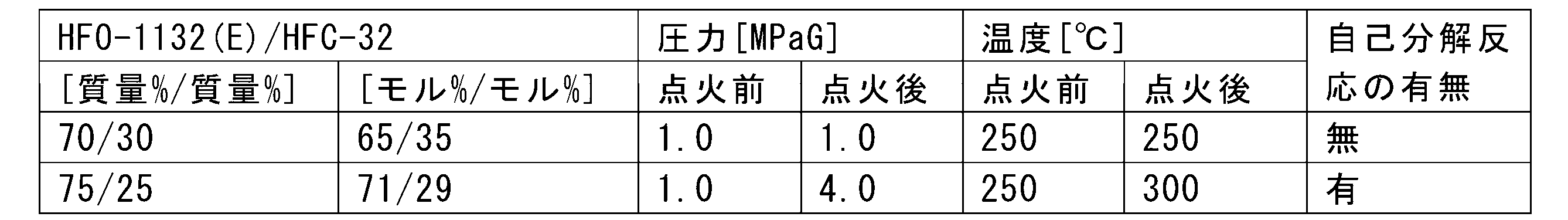
上記表1及び2によれば、組成物全量に対して、ジフルオロエチレンの含有量が65モル%以下であれば安定性の高い組成物となることが分かる。作動媒体とする為に、ジフルオロエチレン(第1の成分)と組合せる化合物(第2の成分)は、少なくとも、自己分解性を有さず、且つオゾン層を破壊することがない化合物である。
(1-2)作動媒体の好ましい組み合わせ
本開示のジフルオロエチレンを含有する作動媒体の製造方法は、前記第2の容器に保持された成分は、飽和ヒドロフルオロカーボン、不飽和ヒドロフルオロカーボン、不飽和ヒドロクロロフルオロカーボン、及び不飽和クロロフルオロカーボンからなる群から選ばれる少なくとも1種である、ことが好ましい。
本開示のジフルオロエチレンを含有する作動媒体の製造方法は、前記第2の容器に保持された成分は、飽和ヒドロフルオロカーボン、不飽和ヒドロフルオロカーボン、不飽和ヒドロクロロフルオロカーボン、及び不飽和クロロフルオロカーボンからなる群から選ばれる少なくとも1種である、ことが好ましい。
これら成分は自己分解性を有しない成分である。
本開示の製造方法では、この様な化合物(第2の成分)として、次の飽和ヒドロフルオロカーボン、不飽和ヒドロフルオロカーボン(以下、「HFC」とも記す)、不飽和ヒドロクロロフルオロカーボン(以下、「HFO」とも記す)、及び不飽和クロロフルオロカーボン(以下、「CFO」と記す)からなる群から選ばれる少なくとも1種の、自己分解性を有しない成分が挙げられる。
本開示の製造方法では、HFCとしては、HFC-32、ジフルオロエタン、トリフルオロエタン、テトラフルオロエタン、ペンタフルオロエタン(HFC-125)、ペンタフルオロプロパン、ヘキサフルオロプロパン、ヘプタフルオロプロパン、ペンタフルオロブタン、ヘプタフルオロシクロペンタン等が挙げられる。
HFCは、中でも、オゾン層への影響が少なく、且つ冷凍サイクル特性が優れる点から、HFC-32、1,1-ジフルオロエタン(HFC-152a)、1,1,1-トリフルオロエタン(HFC-143a)、1,1,2,2-テトラフルオロエタン(HFC-134)、1,1,1,2-テトラフルオロエタン(HFC-134a)、及びHFC-125が好ましく、HFC-32、HFC-134a、及びHFC-125がより好ましく、HFC-32が最も好ましい。
HFCは、1種を単独で用いても良く、2種以上を組み合わせて用いても良い。
本開示の製造方法では、HFOとしては、HFO-1234yf、1,2-ジフルオロエチレン(HFO-1132)、2-フルオロプロペン(HFO-1261yf)、1,1,2-トリフルオロプロペン(HFO-1243yc)、トランス-1,2,3,3,3-ペンタフルオロプロペン(HFO-1225ye(E))、シス-1,2,3,3,3-ペンタフルオロプロペン(HFO-1225ye(Z))、HFO-1234ze(E)、シス-1,3,3,3-テトラフルオロプロペン(HFO-1234ze(Z))、3,3,3-トリフルオロプロペン(HFO-1243zf)等が挙げられる。
HFOは、中でも、HFO-1234yf、HFO-1234ze(E)、HFO-1234ze(Z)が好ましく、HFO-1234yf及びHFO-1234ze(E)がより好ましい。
HFOは、1種を単独で用いても良く、2種以上を組み合わせて用いても良い。
本開示の製造方法では、CFOとしては、クロロフルオロプロペン、クロロフルオロエチレン等が挙げられる。
CFOは、作動媒体のサイクル性能を大きく低下させること無く、作動媒体の燃焼性を抑え易い点から、1,1-ジクロロ-2,3,3,3-テトラフルオロプロペン(CFO-1214ya)、1,3-ジクロロ-1,2,3,3-テトラフルオロプロペン(CFO-1214yb)、1,2-ジクロロ-1,2-ジフルオロエチレン(CFO-1112)が好ましい。
CFOは、1種を単独で用いても良く、2種以上を組み合わせて用いても良い。
本開示のジフルオロエチレンを含有する作動媒体の製造方法は、前記第2の容器に保持された成分は、前記自己分解性を有しない成分を35モル%以上の割合で含有する、ことが好ましい。
本開示の製造方法が対象とする作動媒体は、ジフルオロエチレン(第1の容器内に保持された第1の成分)以外の成分(第2の容器内に保持された成分、前記自己分解性を有しない成分)を35モル%以上の割合で含有することが好ましい。作動媒体としてはジフルオロエチレンと上記組成範囲で組み合せた場合に、従来使用されてきたR410Aの置き換え可能な程度に実用上充分なサイクル性能を有しながら、地球温暖化係数(GWP)が低い作動媒体が好ましい。
GWPとは、気候変動に関する政府間パネル(IPCC)第4次評価報告書(2007年)、100年の値に準じて測定された値である。
本開示のジフルオロエチレンを含有する作動媒体の製造方法は、第1の容器内に、保持された、ジフルオロエチレン(第1の成分)が保持されており、前記ジフルオロエチレンとして、1,1-ジフルオロエチレン(HFO-1132a)、シス-1,2-ジフルオロエチレン(HFO-1132(Z))、及びトランス-1,2-ジフルオロエチレン(HFO-1132(E))からなる群から選ばれる少なくとも1種の成分を含有する、ことが好ましい。ジフルオロエチレンのGWPは、HFO-1132a、HFO-1132(Z)、及びHFO-1132(E)のいずれもGWPは1以下である。
ジフルオロエチレンと組合せる化合物としては、上記組成範囲で組み合せた場合に、得られる作動媒体のGWPを、R410AのGWPの値である2088以下とできる化合物が好ましく、500以下とできる化合物がより好まく、300以下とできる化合物が更に好ましく、150以下とできる化合物が特に好ましい。本開示では、混合物におけるGWPは、混合物中の各成分の質量による加重平均とする。
本開示の製造方法では、ジフルオロエチレンに対して、追加で、HFOとしては、トリフルオロエチレン(HFO-1123)を併用することも可能である。
作動媒体を混合物で構成する場合、混合物が非共沸であると、圧力容器から冷凍空調機器へ充てんされる際に組成変化を生じる点、冷凍空調機器からの冷媒漏えいが生じた場合、冷凍空調機器内の冷媒組成が変化する可能が極めて大きい点等、初期状態への冷媒組成の復元が困難である問題点を有する。
本開示の製造方法が対象とする作動媒体は、上記R410Aの様な擬似共沸混合冷媒であることが、上記問題を回避できる点で好ましい。
混合物の作動媒体における上記性質をはかる指標として、一般に以下に示す「温度勾配」が用いられる。温度勾配は、熱交換器、例えば、蒸発器における蒸発の、又は凝縮器における凝縮の、開始温度と終了温度が異なる性質、と定義される。共沸混合冷媒においては、温度勾配は0であり、R410Aの様な擬似共沸混合冷媒では、温度勾配は極めて0に近い。
温度勾配が大きいと、例えば、蒸発器における入口温度が低下することで着霜の可能性が大きくなり問題である。更に、熱サイクルシステムにおいては、熱交換効率の向上を図る為に、熱交換器を流れる作動媒体と水や空気等の熱源流体を対向流にすることが一般的である。安定運転状態においては、該熱源流体の温度差が小さいことから、温度勾配の大きい非共沸混合媒体の場合、エネルギー効率のよい熱サイクルシステムを得ることが困難である。
本開示の製造方法が対象とする作動媒体は、たとえ非共沸混合媒体であっても、適度に温度勾配が小さい非共沸混合媒体が好ましい。
本開示のジフルオロエチレンを含有する作動媒体の製造方法は、前記第2の容器に保持された成分は、2,3,3,3-テトラフルオロプロペン(HFO-1234yf)及び/又はジフルオロメタン(HFC-32)である、ことが好ましい。
本開示の製造方法が対象とする作動媒体は、ジフルオロエチレンの単独使用による自己分解の問題を解消した上で、上記サイクル性能、GWP、温度勾配の要件をバランス良く保持する作動媒体が好ましい。本開示の製造方法が対象とする作動媒体は、ジフルオロエチレンと組合せる化合物は、HFO-1234yf及び/又はHFC-32が好ましい。
本発明が対象とする作動媒体におけるジフルオロエチレンの含有量の下限については、35モル%が好ましく、40モル%がより好ましい。
本開示の製造方法が対象とする作動媒体は、ジフルオロエチレンは、HFO-1132a、HFO-1132(Z)、及びHFO-1132(E)からなる群から選ばれる少なくとも1種である、ことが好ましい。本開示の製造方法では、ジフルオロエチレンに対して、追加で、HFOとしては、HFO-1123を併用することも可能である。
ジフルオロエチレンとHFO-1234yf及び/又はHFC-32の組合せの組成として具体的には、以下の組成のいずれかであって、かつ作動媒体全量に対するジフルオロエチレンの含有量が65モル%以下である組成が挙げられる。
(i)本開示のジフルオロエチレンを含有する作動媒体の製造方法は、前記第1の容器に保持された成分と前記第2の容器に保持された成分とを混合して得られる作動媒体は、ジフルオロエチレン及びHFO-1234yfを含む作動媒体であって、作動媒体全量に対して、ジフルオロエチレン及びHFO-1234yfの合計量の割合は65モル%~100モル%であり、ジフルオロエチレン及びHFO-1234yfの合計量に対して、ジフルオロエチレンの割合は1モル%~65モル%である、ことが好ましい。
ジフルオロエチレンとHFO-1234yfを含む作動媒体であって、作動媒体全量に対するジフルオロエチレンとHFO-1234yfの合計量の割合が65モル%~100モル%であり、ジフルオロエチレンとHFO-1234yfの合計量に対するジフルオロエチレンの割合が1モル%~65モル%であり、好ましくは10モル%~60モル%であり、より好ましくは20モル%~60モル%である。
(ii)本開示のジフルオロエチレンを含有する作動媒体の製造方法は、前記第1の容器に保持された成分と前記第2の容器に保持された成分とを混合して得られる作動媒体は、ジフルオロエチレン及びHFC-32を含む作動媒体であって、作動媒体全量に対して、ジフルオロエチレン及びHFC-32の合計量の割合は65モル%~100モル%であり、ジフルオロエチレン及びHFC-32の合計量に対して、ジフルオロエチレンの割合は1モル%~65モル%である、ことが好ましい。
ジフルオロエチレンとHFC-32を含む作動媒体であって、作動媒体全量に対するジフルオロエチレンとHFC-32の合計量の割合が65モル%~100モル%であり、ジフルオロエチレンとHFC-32の合計量に対するジフルオロエチレンの割合が1モル%~65モル%であり、好ましくは10モル%~60モル%であり、より好ましくは20モル%~60モル%である。
(iii)本開示のジフルオロエチレンを含有する作動媒体の製造方法は、前記第1の容器に保持された成分と前記第2の容器に保持された成分とを混合して得られる作動媒体は、ジフルオロエチレン、HFO-1234yf及びHFC-32を含む作動媒体であって、作動媒体全量に対して、ジフルオロエチレン、HFO-1234yf及びHFC-32の合計量の割合は65モル%~100モル%であり、ジフルオロエチレン、HFO-1234yf及びHFC-32の合計量に対して、ジフルオロエチレンの割合は1モル%~65モル%であり、HFO-1234yfの割合は98モル%以下であり、且つ、HFC-32の割合は50モル%以下である、ことが好ましい。
ジフルオロエチレンとHFO-1234yfとHFC-32を含む作動媒体であって、作動媒体全量に対するジフルオロエチレンとHFO-1234yfとHFC-32の合計量の割合が65モル%~100モル%であり、ジフルオロエチレンとHFO-1234yfとHFC-32の合計量に対するジフルオロエチレンの割合が1モル%~65モル%であり、HFO-1234yfの割合が98モル%以下であり、且つHFC-32の割合が50モル%以下である。
本開示のジフルオロエチレンを含有する作動媒体の製造方法は、前記第1の容器に保持された成分は、ジフルオロエチレンからなる、ことが好ましい。
本開示のジフルオロエチレンを含有する作動媒体の製造方法は、前記第2の容器に保持された成分は、2,3,3,3-テトラフルオロプロペン及びジフルオロメタンの混合物からなる、ことが好ましい。
本開示のジフルオロエチレンを含有する作動媒体の製造方法は、前記第2の容器に保持された成分は、トランス-1,3,3,3-テトラフルオロプロペンからなる、ことが好ましい。
本開示のジフルオロエチレンを含有する作動媒体の製造方法は、前記第2の容器に保持された成分は、トランス-1,3,3,3-テトラフルオロプロペン及びジフルオロメタンの混合物からなる、ことが好ましい。
(2)製造方法
本開示のジフルオロエチレンを含有する作動媒体の製造方法は、第1の容器内に保持された、ジフルオロエチレンを、65モル%を超える割合で含有する第1の容器に保持された成分と、第2の容器内に保持された、自己分解性を有しない第2の容器に保持された成分とを、次の(A)、(B)又は(C)の工程により混合することを含み、ジフルオロエチレンを、全量に対して、65モル%以下の割合で含有する作動媒体を製造する方法である。
本開示のジフルオロエチレンを含有する作動媒体の製造方法は、第1の容器内に保持された、ジフルオロエチレンを、65モル%を超える割合で含有する第1の容器に保持された成分と、第2の容器内に保持された、自己分解性を有しない第2の容器に保持された成分とを、次の(A)、(B)又は(C)の工程により混合することを含み、ジフルオロエチレンを、全量に対して、65モル%以下の割合で含有する作動媒体を製造する方法である。
(A)工程では、下記(A1)又は(A2)の条件において、前記第2の容器に、第1の容器に保持された成分を供給する。
(A1)条件では、前記供給時における前記第1の容器に保持された成分の温度(t1)をt1<15℃とし、少なくとも前記供給の開始から前記混合が終了するまでの間、前記第2の容器内のゲージ圧力(P2)と前記供給時における前記第1の容器に保持された成分のゲージ圧力(p1)との関係をp1>P2とすると共に、前記第2の容器内の温度(T2)を、T2<15℃の状態に保持する。
(A2)条件では、前記供給時における前記第1の容器に保持された成分を、その温度(t1)が15℃≦t1≦180℃であり、そのゲージ圧力(p1)がp1[MPaG]<1.22-0.0032t1である気体の状態とし、少なくとも前記供給の開始から前記混合が終了するまでの間、前記第2の容器内のゲージ圧力(P2)と前記第1の容器に保持された成分のゲージ圧力(p1)との関係をp1>P2とすると共に、前記第2の容器内の温度(T2)を、T2≦180℃且つT2<(1.22-p1)/0.0032の状態に保持する。
(B)工程では、下記(B1)及び(B2)の条件において、前記第1の容器に、第2の容器に保持された成分を供給する。
(B1)条件では、前記第1の容器内の温度(T1)及びゲージ圧力(P1)を、少なくとも前記供給の開始から前記混合が終了するまで、T1<15℃の状態、又は、15℃≦T1≦180℃且つP1[MPaG]<1.22-0.0032T1の状態に保持する。
(B2)条件では、前記第2の容器に保持された成分は、少なくとも前記供給時において、そのゲージ圧力(p2)がp2>P1である。
(C)工程では、別に準備された第3の容器に、前記第3の容器内の温度(T3)及びゲージ圧力(P3)を、少なくとも以下の供給の開始から前記混合が終了するまでの間、T3<15℃の状態、又は、15℃≦T3≦180℃且つP3[MPaG]<1.22-0.0032T3の状態に保持しながら、前記第1の容器に保持された成分を、下記(C1)又は(C2)の条件で供給し、前記第2の成分を、少なくともその供給時において、そのゲージ圧力(p2)がp2>P3となるように供給する。
(C1)条件では、前記供給時における前記第1の容器に保持された成分の温度(t1)をt1<15℃とし、少なくとも前記供給の開始から前記混合が終了するまでの間、前記第3の容器内のゲージ圧力(P3)と前記供給時における前記第1の容器に保持された成分のゲージ圧力(p1)との関係をp1>P3とすると共に、前記第3の容器内の温度(T3)を、T3<15℃の状態に保持する。
(C2)条件では、前記供給時における前記第1の容器に保持された成分を、その温度(t1)が15℃≦t1≦180℃であり、そのゲージ圧力(p1)がp1[MPaG]<1.22-0.0032t1である気体の状態とし、少なくとも前記供給の開始から前記混合が終了するまでの間、前記第3の容器内のゲージ圧力(P3)と前記第1の容器に保持された成分のゲージ圧力(p1)との関係をp1>P3とすると共に、前記第3の容器内の温度(T3)をT3≦180℃且つT3<(1.22-p1)/0.0032の状態に保持する。
本開示の製造方法は、上記第1の容器に保持された成分及び第2の容器に保持された成分を混合する為に、上記(A)、(B)、(C)のいずれか1つの工程を有する。
以下、図1~図6を参照し、各成分及び各工程を具体的に説明する。
(2-1)第1の容器に保持された成分
第1の容器に保持された成分は、ジフルオロエチレンを、65モル%を超える割合で含有する。第1の容器に保持された成分においてはジフルオロエチレンの含有量が65モル%を超えると自己分解し易い。本開示の製造方法における第2の容器に保持された成分との混合の操作において、その第1の容器に保持された成分が自己分解しない条件下で扱われることが必要となる。第1の容器に保持された成分においては、ジフルオロエチレン含有量が100モル%である場合に、最も自己分解し易い。
第1の容器に保持された成分は、ジフルオロエチレンを、65モル%を超える割合で含有する。第1の容器に保持された成分においてはジフルオロエチレンの含有量が65モル%を超えると自己分解し易い。本開示の製造方法における第2の容器に保持された成分との混合の操作において、その第1の容器に保持された成分が自己分解しない条件下で扱われることが必要となる。第1の容器に保持された成分においては、ジフルオロエチレン含有量が100モル%である場合に、最も自己分解し易い。
工程(A)、工程(B)及び工程(C)における安定性確保の為の条件設定を行う場合には、第1の容器に保持された成分がジフルオロエチレンのみで構成される場合として条件を設定すれば、第1の容器に保持された成分においてジフルオロエチレンの含有量がそれ以外の場合においても安定性は確保される。
第1の容器に保持された成分が、ジフルオロエチレンの100モル%で構成される場合、その自己分解性は温度(t)と圧力(p)の関係により制御される。
<図1>
図1は、ジフルオロエチレン(HFO-1132(E))が自己分解を起こす温度(t)と圧力(ゲージ圧)(p)の条件を示すグラフであり、点線で示す直線が自己分解性の有無の境界を示す。直線が示す式は、p[MPaG]=1.22-0.0032tである。
図1は、ジフルオロエチレン(HFO-1132(E))が自己分解を起こす温度(t)と圧力(ゲージ圧)(p)の条件を示すグラフであり、点線で示す直線が自己分解性の有無の境界を示す。直線が示す式は、p[MPaG]=1.22-0.0032tである。
参考として、トリフルオロエチレン(HFO-1123)の場合、直線が示す式は、p[MPaG]=1.13-0.0029tである。
図1において、その直線より上の領域が自己分解性を有する状態であり、その直線より下の領域が自己分解性を有しない領域である。即ち、pが1.22-0.0032tより小さい状態においては、ジフルオロエチレンは自己分解性を有しない。
以下、この直線を「自己分解境界線」ともいう。
図1において、〇で示される点は、該温度条件及び圧力(ゲージ圧)条件において上記方法により自己分解性の評価を行い、自己分解性無と評価された点であり、×で示される点は自己分解性有と評価された点である。これらの実測値に基づいて上記式を求めた。点火前は種々の割合で混合した混合媒体を所定圧力まで封入した後、内部に設置された白金線を溶断していない時点をいい、点火後とは金線を溶断することにより約30Jのエネルギーを印加した時点をいう。
本発明の製造方法において、第1の容器に保持された成分としては、例えば、1,1,2-トリフルオロエタン(HFC143)の脱フッ酸等の方法で得られる粗ジフルオロエチレンを蒸留して、ジフルオロエチレンの含有量が65モル%~100モル%程度の範囲に調整された精製ジフルオロエチレンを用いることができる。
第1の容器に保持された成分は、ジフルオロエチレン以外の化合物を、第1の容器に保持された成分全量に対して35モル%未満の割合で含有しても良い。第1の容器に保持された成分が含有しても良いジフルオロエチレン以外の化合物としては、例えば、ジフルオロエチレンの製造時に生成された副生物、第2の容器に保持された成分が含有する飽和ヒドロフルオロカーボン、不飽和ヒドロフルオロカーボン、不飽和ヒドロクロロフルオロカーボン及び不飽和クロロフルオロカーボンから選ばれる少なくとも1種等が挙げられる。
このようにして得られる第1の容器に保持された成分の保存時における安定性確保の条件については、上記と同様に、最も自己分解し易い、ジフルオロエチレンの含有量が100モル%である場合に安定とされる条件を設定すれば、第1の容器に保持された成分においてジフルオロエチレンの含有量がそれ以外の場合においても保存時の安定性が確保される。
よって、第1の容器に保持された成分について、ジフルオロエチレンの含有量が100モル%の場合を例に以下に説明する。
ジフルオロエチレンは、その温度(t)と圧力(p)がp[MPaG]<1.22-0.0032tとなるような状態で保存されることで保存時の安定性が確保される。特定の容器内に、ジフルオロエチレンの液体のみが存在するような状態で保存可能であれば、その場合は自己分解を起こさず安定に保存が可能である。
<図2>
図2にジフルオロエチレンが液体となる温度と圧力の関係(蒸気圧曲線)を示すグラフを、図1のグラフに重ねて示す。図2において、実線で示す曲線が蒸気圧曲線であり、蒸気圧曲線の右側の領域ではジフルオロエチレンは気体であり、左側の領域においてジフルオロエチレンは液体である。上に説明した、ジフルオロエチレンの液体のみが存在するような状態とは、図2における蒸気圧曲線より左側の液体領域のことをいう。
図2にジフルオロエチレンが液体となる温度と圧力の関係(蒸気圧曲線)を示すグラフを、図1のグラフに重ねて示す。図2において、実線で示す曲線が蒸気圧曲線であり、蒸気圧曲線の右側の領域ではジフルオロエチレンは気体であり、左側の領域においてジフルオロエチレンは液体である。上に説明した、ジフルオロエチレンの液体のみが存在するような状態とは、図2における蒸気圧曲線より左側の液体領域のことをいう。
ここで、通常、ジフルオロエチレンの液体を容器に入れて保存する場合は、ジフルオロエチレンの液体と気体が共存する気液混合状態で保存される。気液混合状態の温度及び圧力は、蒸気圧曲線上の温度及び圧力で示されるが、ジフルオロエチレンが気液混合状態で安定な状態を示すのは、温度180℃以下且つ自己分解境界線より下の領域である。具体的には、蒸気圧曲線における自己分解境界線の交点(温度15℃、圧力1.2MPaG)未満の領域である。
これらを勘案すると、ジフルオロエチレンの保存好適領域としては、図2において斜線を付した領域、即ち、t=180℃の直線と、p=1.22-0.0032tの直線と蒸気圧曲線で囲まれた領域、但しp=1.22-0.0032tの線上は除く領域が挙げられる。
本開示において、ジフルオロエチレンの「保存好適領域」は、図2における上記斜線領域を示す用語として用いる。ジフルオロエチレンの液体を容器に入れて保存する場合であっても、液体が充填されていない部分をジフルオロエチレン以外のジフルオロエチレンの保存に影響を及ぼさない気体、例えば、窒素等に全て置き換えることができれば、図2における蒸気圧曲線より左側の液体領域の温度及び圧力での安定な保管は可能である。
(2-2)第2の容器に保持された成分
第2の容器に保持された成分は、飽和ヒドロフルオロカーボン、不飽和ヒドロフルオロカーボン、不飽和ヒドロクロロフルオロカーボン及び不飽和クロロフルオロカーボンから選ばれる少なくとも1種を35モル%以上の割合で含有し、これらは自己分解性を有しない成分である。
第2の容器に保持された成分は、飽和ヒドロフルオロカーボン、不飽和ヒドロフルオロカーボン、不飽和ヒドロクロロフルオロカーボン及び不飽和クロロフルオロカーボンから選ばれる少なくとも1種を35モル%以上の割合で含有し、これらは自己分解性を有しない成分である。
第2の容器に保持された成分が含有する飽和ヒドロフルオロカーボン、不飽和ヒドロフルオロカーボン、不飽和ヒドロクロロフルオロカーボン及び不飽和クロロフルオロカーボンから選ばれる少なくとも1種としては、上記で例示した各化合物が挙げられる。好ましい化合物及びそれらの組合せも上記同様である。第2の容器に保持された成分は、ジフルオロエチレンを65モル%未満の割合で含有する自己分解性を有しない混合物であってもよい。
第2の容器に保持された成分は、第1の容器に保持された成分と所定の割合で混合された際に、上記本発明の製造方法が対象とする作動媒体、すなわち、少なくともジフルオロエチレンを65モル%以下の割合で含有する作動媒体が得られる組成であればよい。好ましくは、上記(i)~(iii)の組成のいずれかの作動媒体が得られる組成とする。このような観点から第2の容器に保持された成分は、HFO-1234yf及び/又はHFC-32からなることが好ましい。
工程(A)、工程(B)及び工程(C)
本開示の製造方法において、上記第1の容器に保持された成分は第1の容器に保持され、上記第2の容器に保持された成分は第2の容器に保持されて準備される。そして、第1の容器に保持された成分と第2の容器に保持された成分の混合が、工程(A)、工程(B)、又は工程(C)のうちのいずれか1つの工程により行われる。
本開示の製造方法において、上記第1の容器に保持された成分は第1の容器に保持され、上記第2の容器に保持された成分は第2の容器に保持されて準備される。そして、第1の容器に保持された成分と第2の容器に保持された成分の混合が、工程(A)、工程(B)、又は工程(C)のうちのいずれか1つの工程により行われる。
本開示の製造方法において、特に断りのない限り圧力はゲージ圧である。
(2-3)工程(A)
本開示の製造方法において、工程(A)は、第2の容器に保持された成分を保持する第2の容器に(A1)又は(A2)の条件で第1の容器に保持された成分を供給する工程である。
本開示の製造方法において、工程(A)は、第2の容器に保持された成分を保持する第2の容器に(A1)又は(A2)の条件で第1の容器に保持された成分を供給する工程である。
(A)工程では、下記(A1)又は(A2)の条件において、前記第2の容器に、第1の容器に保持された成分を供給する。
(A1)条件では、前記供給時における前記第1の容器に保持された成分の温度(t1)をt1<15℃とし、少なくとも前記供給の開始から前記混合が終了するまでの間、前記第2の容器内のゲージ圧力(P2)と前記供給時における前記第1の容器に保持された成分のゲージ圧力(p1)との関係をp1>P2とすると共に、前記第2の容器内の温度(T2)を、T2<15℃の状態に保持する。
(A2)条件では、前記供給時における前記第1の容器に保持された成分を、その温度(t1)が15℃≦t1≦180℃であり、そのゲージ圧力(p1)がp1[MPaG]<1.22-0.0032t1である気体の状態とし、少なくとも前記供給の開始から前記混合が終了するまでの間、前記第2の容器内のゲージ圧力(P2)と前記第1の容器に保持された成分のゲージ圧力(p1)との関係をp1>P2とすると共に、前記第2の容器内の温度(T2)を、T2≦180℃且つT2<(1.22-p1)/0.0032の状態に保持する。
本開示のジフルオロエチレンを含有する作動媒体の製造方法は、前記(A)工程において、前記第1の容器内の温度及び前記第2の容器内の温度は、共に15℃未満に保持され、前記第1の容器に保持された成分をt1<15℃の液体の状態で前記第2の容器に供給する、ことが好ましい。
以下の(A1)及び(A2)で規定する条件は、第1の容器に保持された成分を第2の容器に供給する際の第1の容器に保持された成分の温度(t1)及び圧力(p1)と、少なくとも第1の容器に保持された成分の第2の容器への供給の開始から、その供給により第2の容器内で行われる第1の容器に保持された成分と第2の容器に保持された成分の混合が終了するまでの間の、第2の容器内の温度(T2)及び圧力(P2)に関する。
本開示において、「供給時」の温度、圧力とは、ある容器に保持された成分が容器に進入する時点の温度、圧力をいい、特に断りのない限り、供給が連続して行われる場合において、供給の開始から終了まで一定の状態に保持される。
(A)工程におけるこれらの条件は全て、第1の容器に保持された成分におけるジフルオロエチレンの含有量が100モル%の場合において安定である条件を基準として設定している。このことから、(A)工程において上記条件は、規定された範囲内の如何なる組成の第1の容器に保持された成分と如何なる組成の第2の容器に保持された成分を混合して、如何なる組成の作動媒体を製造する場合においても安定性を確保できる条件と言える。
第1の容器に保持された成分におけるジフルオロエチレンの含有量が100モル%の場合において安定である条件を基準としてなされる条件設定は、後述の(B)工程及び(C)工程においても適用されており、よって、(B)工程及び(C)工程においても、上記(A)工程と同様に安定性を確保できると言える。
(A1)条件では、前記供給時における前記第1の容器に保持された成分の温度(t1)をt1<15℃とし、少なくとも前記供給の開始から前記混合が終了するまでの間、前記第2の容器内のゲージ圧力(P2)と前記供給時における前記第1の容器に保持された成分のゲージ圧力(p1)との関係をp1>P2とすると共に、前記第2の容器内の温度(T2)を、T2<15℃の状態に保持する。
(A2)条件では、前記供給時における前記第1の容器に保持された成分を、その温度(t1)が15℃≦t1≦180℃であり、そのゲージ圧力(p1)がp1[MPaG]<1.22-0.0032t1である気体の状態とし、少なくとも前記供給の開始から前記混合が終了するまでの間、前記第2の容器内のゲージ圧力(P2)と前記第1の容器に保持された成分のゲージ圧力(p1)との関係をp1>P2とすると共に、前記第2の容器内の温度(T2)を、T2≦180℃且つT2<(1.22-p1)/0.0032の状態に保持する。
工程(A)における上記(A1)及び(A2)の条件において、共通する条件は、第1の容器に保持された成分を第2の容器に供給する際の第1の容器に保持された成分の圧力(p1)と第2の容器内の圧力(P2)の関係がp1>P2であるという圧力に関する条件である。この圧力の条件は第1の容器に保持された成分を第2の容器に供給する際の必須条件である。(A1)及び(A2)は、第1の容器に保持された成分を第2の容器に供給する際の、p1>P2という必須の圧力条件下での、供給時における第1の容器に保持された成分の温度(t1)、圧力(p1)と第2の容器内の温度(T2)の関係を夫々示すものである。
工程(A)において第2の容器は、少なくとも第1の容器に保持された成分の供給の開始から、その供給により第2の容器内で行われる第1の容器に保持された成分と第2の容器に保持された成分の混合が終了するまでの間、温度(T2)と圧力(P2)を上記(A1)又は(A2)の状態とすればよい。
上記混合の終了時には、第2の容器内には、本発明の実施形態における安定な組成の作動媒体が貯留物として得られている。この様に、上記供給の開始前及び混合終了後において、第2の容器内に収容される第2の容器に保持された成分、及び、本開示の実施形態に係る作動媒体は、共に自己分解性を有しないものであり、自己分解の観点から取り扱いについて特に留意する点は無い。上記混合の終了時とは、後述の通り、通常、第1の容器に保持された成分の供給を停止した時点である。
第1の容器に保持された成分を保持する第1の容器内の温度(T1)及び圧力(P1)は、常に、上記に示した第1の容器に保持された成分におけるジフルオロエチレンの含有量が100モル%の場合においても安定である条件の範囲の温度及び圧力、好ましくは180℃以下かつ自己分解境界線より下の領域の温度及び圧力、より好ましくは保存好適領域内の温度及び圧力で保持される。
通常、第2の容器に保持された成分を保持する第2の容器に、第1の容器に保持された成分を供給する際には、第1の容器と第2の容器を接続する供給管を配設し、第1の容器に保持された成分はその供給管を介して第2の容器に供給される。第1の容器と第2の容器を繋ぐ供給管は、通常、第1の容器に保持された成分の供給のON及びOFFや時間当たりの供給量を制御する手段を有し、必要に応じて、圧力調整手段、温度調整手段を有する。工程(A)においては、この工程の必須の条件であるp1>P2を達成する為に、通常、供給管に配設された圧力調整手段、典型的にはポンプが用いられる。
供給時における第1の容器に保持された成分の温度(t1)及び圧力(p1)は、必ずしも、第1の容器内で温度(T1)及び圧力(P1)で保持された第1の容器に保持された成分の温度及び圧力の条件と一致するわけではない。図2に、第2の容器内への第1の容器に保持された成分の供給を安定に行う為に取り得る、供給時における第1の容器に保持された成分の温度(t1)と圧力(p1)の範囲を、塗り潰して示す。
供給時における第1の容器に保持された成分の温度(t1)と圧力(p1)が、図2において、(A1)条件の塗り潰されたt1<15℃の領域(以下、「低温領域」と記す)内、又は、、(A2)条件の格子模様で示される15℃≦t1≦180℃、p1[MPaG]<1.22-0.0032t1である気体の領域(以下、「低圧領域」と記す)内にあれば、上記p1>P2の圧力条件下で、第2の容器内の温度(T2)を所定の条件、具体的には夫々(A1)及び(A2)の条件に設定することで第1の容器に保持された成分の供給を安定に行うことができる。この際、第2の容器へ第1の容器に保持された成分を供給する時間当たりの供給量の調整を行うことが好ましい。
(A1)は、低温領域にある第1の容器に保持された成分を、同じ温度領域でより圧力の低い状態の第2の容器に、供給する条件設定であり、この条件を満たせば第2の容器の安定は確保できる。
(A2)は、低圧領域にある第1の容器に保持された成分を、より圧力が低く、温度(T2)が180℃以下で且つ第1の容器に保持された成分の温度(t1)が第2の容器内の温度(T2)まで上昇したとしても、圧力(p1)が自己分解境界線の下となる様な状態の第2の容器に、供給する条件設定であり、この条件を満たせば第2の容器の安定は確保できる。
第1の容器に保持された成分を第2の容器に保持された成分に混合する場合、効率の点から、両成分共に液体の状態で混合することが好ましい。この条件を適用させる為には、例えば、第1の容器内で第1の容器に保持された成分を15℃未満の液体として保持する。通常、第1の容器に保持された成分は気体と液体が共存する状態で保存されるのが好ましい。第1の容器は、温度及び圧力が、好ましくは、温度が15℃未満で、且つジフルオロエチレンの蒸気圧曲線上にある状態に調整される。
第2の容器への第1の容器に保持された成分の供給を液体で行うには、p1>P2を満たすと共に、低温領域且つ液体の領域となる様に、供給時の第1の容器に保持された成分の温度(t1)、圧力(p1)を調整する。この場合、第2の容器内の温度条件は上記(1)によりT2<15℃の状態とする。第2の容器に保持された成分の状態は液体とすることが好ましく、第2の容器がおかれる条件、即ち、p1>P2、T2<15℃の条件の範囲で第2の容器に保持された成分が液体となる条件を選択する。
<図3>
図3は、第1の容器に保持された成分及び第2の容器に保持された成分が共に15℃未満の液体である場合の(A)工程の一例を模式的に示す図である。
図3は、第1の容器に保持された成分及び第2の容器に保持された成分が共に15℃未満の液体である場合の(A)工程の一例を模式的に示す図である。
図3の(4a)において、第1の容器に保持された成分11として、1,1,2-トリフルオロエタン(HFC143)の脱フッ酸等の方法で得られた粗ジフルオロエチレンを蒸留器4に供給して、缶出液貯留槽6に缶出液として副生物を除去し、塔頂から得られる留分について、これを、冷却凝縮手段5を介して留出液としたジフルオロエチレン(液)が準備される。ジフルオロエチレン(液)11は第1の容器1に貯留された状態で得られる。第1の容器に保持された成分は、市販の容器入りの第1の容器に保持された成分であっても良い。
図3では、第1の容器1に貯留された状態で得られるジフルオロエチレン(液)11を、別に準備された第2の容器に保持された成分(液)12が貯留された第2の容器2に供給する。図3(4b)は、第1の容器に保持された成分11が第2の容器2に供給される前の状態を示す図であり、図3(4c)は、第1の成分11が第2の容器2に供給されて作動媒体13が得られた状態を示す図である。第2の容器に保持された成分については、第1の容器に保持された成分と同様に、公知の方法で製造され、蒸留により精製して得られる缶出液又は留出液を第2の容器に貯留したものであっても良く、市販の容器入りの第2の容器に保持された成分であっても良い。
例えば、第1の容器1内の温度(T1)は、15℃未満であり、圧力(P1)は、第1の容器に保持された成分が液体となる条件、具体的には-50℃以上15℃未満において上記蒸気圧曲線上の圧力に調整される。第1の容器1内の第1の容器に保持された成分の温度、圧力は第1の容器内の温度(T1)、圧力(P1)と同じである。
図3では、第1の容器1は排出口を有し、第2の容器2は供給口を有すると共に、これらはポンプ14を介して気体又は液体が流通可能な供給管7及び供給管8で接続されている。第1の容器1内の第1の容器に保持された成分11は、第1の容器1が有する排出口から、ポンプ14を介して供給管7及び供給管8内を、第2の容器2が有する供給口まで移動し第2の容器2内に供給される。第1の容器1が有する排出口からポンプ14までを供給管7が接続し、ポンプ14から第2の容器2は供給口までを供給管8が接続する。
第2の容器2は、温度(T2)が15℃未満であって、圧力(P2)が第2の容器2内に保持される第2の容器に保持された成分が液体の状態となる圧力に設定し、保持される。
第2の容器2内の圧力(P2)が第1の容器1内の圧力(P1)より低い場合、通常、第1の容器に保持された成分の自圧で移動が行われる。この場合、第2の容器に、供給される第1の容器に保持された成分の供給時の圧力(p1)と温度(t1)とは、第1の容器内の温度(T1)、圧力(P1)と同じである。この場合、圧力の関係はP1=p1>P2である。
圧力(P2)が圧力(P1)より高い場合、ポンプ14により、第1の容器に保持された成分の供給時の圧力(p1)が第2の容器2内の圧力(P2)より高い状態に加圧される。この場合、加圧後の第1の容器に保持された成分の温度(t1)は、加圧前の温度(T1)と同じである必要はないが、15℃未満を保持する範囲で加圧される。即ち、第1の容器に保持された成分は低温領域の液体として、第2の容器内に供給される。
図3では、この場合、第1の容器1とポンプ14を接続する供給管7内の第1の容器に保持された成分の温度と圧力とは、第1の容器1の温度(T1)、圧力(P1)と同じである。一方、ポンプ14と第2の容器2を接続する供給管8内の第1の容器に保持された成分の温度と圧力は、供給時の第1の容器に保持された成分の温度(t1)と圧力(p1)と同じであり、圧力についてはP1<P2<p1の関係となる。
この例において、(A)工程を実行する場合の条件は、上記(A1)の場合に相当する。したがって、少なくとも第1の容器に保持された成分の供給の開始から第1の容器に保持された成分と第2の容器に保持された成分の混合が終了するまでの間、第2の容器2の温度(T2)を15℃未満に保持する。
図3では、この様にして、第2の容器2内への第1の容器に保持された成分11の供給により、第2の容器2内では第2の容器に保持された成分12と第1の容器に保持された成分11の混合が行われる。第1の容器に保持された成分11の供給は、第2の容器2内の貯留物が目的とする作動媒体13の組成となった時点で停止される。第1の容器に保持された成分11の供給の停止は、第2の容器2内の貯留物の組成を連続的に計測できる手段を設け、該手段が目的とする作動媒体13の組成を計測した時点で行うことが好ましい。目的とする作動媒体13の組成に合わせて予め、混合する第1の容器に保持された成分と第2の容器に保持された成分の量を調整しておいてもよい。
第1の容器に保持された成分及び第2の容器に保持された成分が共に15℃未満の液体である場合の(A)工程を、例えば図4に示す様に行うことも可能である。図4は、第1の容器に保持された成分及び第2の容器に保持された成分を共に15℃未満の液体として(A)工程を行う際に、第2の容器内に保持された第2の容器に保持された成分の液中に第1の容器に保持された成分を液体の状態で供給する操作を模式的に示す図である。
図3に示す方法において供給管8がポンプ14と第2の容器2の供給口を接続するように配設されている。
<図4>
図4に示す方法では、供給管8は、一方の端部がポンプ14に接続され、ポンプ14から第2の容器2の供給口を経て第2の容器に保持された成分(液)12中に他方の端部が到達するように配設されている。それ以外で異なる点は無い。図4に示す方法においても、上記で説明した、第1の容器に保持された成分及び第2の容器に保持された成分が共に15℃未満の液体である場合の(A)工程を実行する条件は変わらない。
図4に示す方法では、供給管8は、一方の端部がポンプ14に接続され、ポンプ14から第2の容器2の供給口を経て第2の容器に保持された成分(液)12中に他方の端部が到達するように配設されている。それ以外で異なる点は無い。図4に示す方法においても、上記で説明した、第1の容器に保持された成分及び第2の容器に保持された成分が共に15℃未満の液体である場合の(A)工程を実行する条件は変わらない。
例えば、図4に示す様に、第2の容器内に保持された第2の容器に保持された成分の液中に第1の容器に保持された成分を液体の状態で供給する利点は、第2の容器に保持された成分と第1の容器に保持された成分の混合が促進されることにある。
(2-4)工程(B)
本開示の製造方法において、工程(B)は、第1の容器に保持された成分を保持する第1の容器に以下の(B1)及び(B2)の条件で第2の容器に保持された成分を供給する工程である。
本開示の製造方法において、工程(B)は、第1の容器に保持された成分を保持する第1の容器に以下の(B1)及び(B2)の条件で第2の容器に保持された成分を供給する工程である。
(B)工程では、下記(B1)及び(B2)の条件において、前記第1の容器に、第2の容器に保持された成分を供給する。
(B1)条件では、前記第1の容器内の温度(T1)及びゲージ圧力(P1)を、少なくとも前記供給の開始から前記混合が終了するまで、T1<15℃の状態、又は、15℃≦T1≦180℃且つP1[MPaG]<1.22-0.0032T1の状態に保持する。
(B2)条件では、前記第2の容器に保持された成分は、少なくとも前記供給時において、そのゲージ圧力(p2)がp2>P1である。
本開示のジフルオロエチレンを含有する作動媒体の製造方法は、前記(B)工程において、前記第1の容器内の温度及び前記第2の容器内の温度は、共に15℃未満に保持され、前記第2の容器に保持された成分をt2<15℃の液体の状態で前記第1の容器に供給する、ことが好ましい。
工程(B)における上記(B2)の条件は、第2の容器に保持された成分を第1の容器に供給する際の第2の容器に保持された成分の圧力(p2)と第1の容器内の圧力(P1)の関係がp2>P1であるという圧力に関する条件である。この圧力の条件は第2の容器に保持された成分を第1の容器に供給する際の必須条件である。
上記(B1)の条件は、少なくとも、第1の容器への第2の容器に保持された成分の供給の開始から、この供給により第1の容器内で行われる第1の容器に保持された成分と第2の容器に保持された成分の混合が終了するまで、上記図3に示す低温領域内又は低圧領域内に、第1の容器内の温度(T1)及び圧力(P1)を保持するという条件である。ここで、上記混合の終了時とは、通常、第2の容器に保持された成分の供給を停止した時点である。
第1の容器に保持された成分を保持する第1の容器内の温度(T1)及び圧力(P1)は、第2の容器に保持された成分の供給の開始の前までは、上記に示した第1の容器に保持された成分におけるジフルオロエチレンの含有量が100モル%の場合においても安定である条件の範囲の温度及び圧力、好ましくは180℃以下且つ自己分解境界線より下の領域の温度及び圧力、より好ましくは保存好適領域内の温度及び圧力で保持される。また、上記混合の終了時には、第1の容器内には、本発明の実施形態における安定な組成の作動媒体が貯留物として得られている。この作動媒体は自己分解性を有しないものであり、よって上記混合終了後は第1の容器について、自己分解の観点から取り扱いに特に留意する点はない。
工程(B)において第2の容器2の温度(T2)及び圧力(P2)は特に制限されない。第2の容器2内における第2の容器に保持された成分の温度及び圧力は、温度(T2)及び圧力(P2)と同じであるが、第1の容器1への供給時における第2の容器に保持された成分の温度(t2)及び圧力(p2)は、例えば、以下の手段により調整できる。
通常、第1の容器に保持された成分を保持する第1の容器に第2の容器に保持された成分を供給する際には、第2の容器と第1の容器を接続する供給管を配設し、第2の容器に保持された成分は該供給管を介して第1の容器に供給される。第1の容器と第2の容器を繋ぐ供給管は、通常、第2の容器に保持された成分の供給のON、OFFや、時間当たりの供給量を制御する手段を有し、必要に応じて、圧力調整手段、温度調整手段を有する。工程(B)においては、該工程の必須の条件であるp2>P1を達成するために、通常、供給管に配設された圧力調整手段、典型的にはポンプが用いられる。
工程(B)において、第2の容器に保持された成分の供給の開始から上記混合の終了まで、第1の容器内の温度(T1)及び圧力(P1)を図5に示す低温領域内又は低圧領域内に保持する為には、温度(T1)及び圧力(P1)が該範囲内に収まる様に、第1の容器に、供給する第2の容器に保持された成分の供給時における温度(t2)及び圧力(p2)、更には時間当たりの供給量を調整する。
例えば、第1の容器内の温度(T1)及び圧力(P1)が低温領域にある場合には、第2の容器に保持された成分の供給時における温度(t2)及び圧力(p2)を低温領域内に設定する。また、第1の容器内の温度(T1)及び圧力(P1)が低圧領域にある場合、第2の容器に保持された成分の供給時における温度(t2)及び圧力(p2)を低圧領域内に設定する等が挙げられる。
この場合、より安定には、圧力(p2)が低圧領域内であって、t2<(1.22-P1)/0.0032である条件が挙げられる。
この(B)工程においても、上記(A)工程の場合と同様に、効率を重視すれば、第1の容器に保持された成分及び第2の容器に保持された成分共に液体の状態で混合することが好ましい。
この条件を適用させる為には、例えば、第2の容器に保持された成分が供給される以前において、第1の容器内で第1の容器に保持された成分を15℃未満の液体として保持する。通常は、第1の容器に保持された成分は気体と液体が共存する状態で保存されるのが好ましい。第1の容器は、第2の容器に保持された成分が供給される以前において、温度及び圧力が、好ましくは、温度が15℃未満で、且つジフルオロエチレンの蒸気圧曲線上にある状態に調整される。
この様な状態の第1の容器に、上記(B1)及び(B2)の条件に適合する様にして15℃未満の液体の状態で、p2>P1の第2の容器に保持された成分を供給して、温度が15℃未満で、かつジフルオロエチレンの蒸気圧曲線上にある液体の第1の容器に保持された成分と混合する。(B)工程においては、好ましくは、上記のようにして、第1の容器に保持された成分及び第2の容器に保持された成分共に液体の状態で混合することができる。
<図5>
図5は、第1の容器に保持された成分及び第2の容器に保持された成分が共に15℃未満の液体である場合の(B)工程の一例を模式的に示す図である。第1の容器に保持された成分11が保持された第1の容器1及び第2の容器に保持された成分12が保持された第2の容器2は、上記(A)工程と同様に準備できる。
図5は、第1の容器に保持された成分及び第2の容器に保持された成分が共に15℃未満の液体である場合の(B)工程の一例を模式的に示す図である。第1の容器に保持された成分11が保持された第1の容器1及び第2の容器に保持された成分12が保持された第2の容器2は、上記(A)工程と同様に準備できる。
図5には、第2の容器2に保持された第2の容器に保持された成分(液)12を、第1の容器に保持された成分(液)11が保持された第1の容器1に、供給する操作が示されている。図5(6a)は、第2の容器に保持された成分12が第1の容器1に供給される前の状態を示す図であり、図5(6b)は、第2の容器に保持された成分12が第1の容器1に供給されて作動媒体13が得られた状態を示す図である。
図5(6a)では、例えば、第1の容器1内の温度(T1)は、上記の通り、15℃未満であり、圧力(P1)は、第1の容器に保持された成分が液体となる条件、具体的には-50℃以上15℃未満において上記蒸気圧曲線上の圧力に調整される。第1の容器1内の第1の容器に保持された成分の温度、圧力は第1の容器内の温度(T1)、圧力(P1)と同じである。
図5では、第2の容器2は排出口を有し、第1の容器1は供給口を有すると共に、これらはポンプ14を介して気体又は液体が流通可能な供給管9及び供給管10で接続されている。第2の容器2内の第2の容器に保持された成分12は、第2の容器2が有する排出口から、ポンプ14を介して供給管9及び供給管10内を、第1の容器1が有する供給口まで移動し、第1の容器1内に供給される。第2の容器2が有する排出口からポンプ14までを供給管9が接続し、ポンプ14から第1の容器1は供給口までを供給管10が接続する。
図5では、第2の容器2は、温度(T2)が15℃未満であって、圧力(P2)が第2の容器2内に保持される第2の容器に保持された成分が液体の状態となる圧力に設定、保持される。第1の容器1内の圧力(P1)が第2の容器2内の圧力(P2)より低い場合、通常、第2の容器に保持された成分の自圧で移動が行われる。この場合、第1の容器に供給される第2の容器に保持された成分の供給時の圧力(p2)と温度(t2)とは、第2の容器内の温度(T2)、圧力(P2)と同じである。この場合、圧力の関係はP2=p2>P1である。
図5では、圧力(P1)が圧力(P2)より高い場合、ポンプ14により、第2の容器に保持された成分の供給時の圧力(p2)が第1の容器1内の圧力(P1)より高い状態に加圧される。この場合、加圧後の第2の容器に保持された成分の温度(t2)は、加圧前の温度(T2)と同じである必要はないが、15℃未満を保持する範囲で加圧される。即ち、第2の容器に保持された成分は低温領域の液体として、第1の容器内に供給される。この場合、第2の容器2とポンプ14を接続する供給管9内の第2の容器に保持された成分の温度と圧力とは、第2の容器2の温度(T2)、圧力(P2)と同じである。一方、ポンプ14と第1の容器1を接続する供給管10内の第2の容器に保持された成分の温度と圧力とは、供給時の第2の容器に保持された成分の温度(t2)と圧力(p2)と同じであり、圧力についてはP2<P1<p2の関係となる。
この例において、(B)工程を実行する場合の条件は、上記(B1)及び(B2)による。従って、少なくとも第2の容器に保持された成分の供給の開始から第2の容器に保持された成分と第1の容器に保持された成分の混合が終了するまでの間、第1の容器1の温度(T1)を15℃未満に保持する。
図5では、この様にして、第1の容器1内への第2の容器に保持された成分12の供給により、第1の容器1内では第2の容器に保持された成分12と第1の容器に保持された成分11の混合が行われる。第2の容器に保持された成分12の供給は、第1の容器1内の貯留物が目的とする作動媒体13の組成となった時点で停止される。第2の容器に保持された成分12の供給の停止は、第1の容器1内の貯留物の組成を連続的に計測できる手段を設け、該手段が目的とする作動媒体13の組成を計測した時点で行うことが好ましい。目的とする作動媒体13の組成に合わせて予め、混合する第1の容器に保持された成分と第2の容器に保持された成分の量を調整しておいても良い。
第1の容器に保持された成分及び第2の容器に保持された成分を共に15℃未満の液体として(B)工程を行う際に、第1の容器内に保持された第1の容器に保持された成分の液中に第2の成分を液体の状態で供給する方法をとっても良い。この様に、第1の容器内に保持された第1の容器に保持された成分の液中に第2の容器に保持された成分を液体の状態で供給する利点は、第2の容器に保持された成分と第1の容器に保持された成分との混合が促進されることにある。
(2-5)工程(C)
本開示の製造方法において、工程(C)は、別に準備された第3の容器に、前記第3の容器内の温度(T3)及びゲージ圧力(P3)を、少なくとも以下の供給の開始から前記混合が終了するまでの間、T3<15℃(低温領域)の状態、又は、15℃≦T3≦180℃且つP3[MPaG]<1.22-0.0032T3(低圧領域)の状態に保持する。前記第1の容器に保持された成分を、以下の(C1)又は(C2)の条件で供給すると共に、前記第2の容器に保持された成分を、少なくとも供給時において、そのゲージ圧力(p2)がp2>P3となる様に供給する工程である。
本開示の製造方法において、工程(C)は、別に準備された第3の容器に、前記第3の容器内の温度(T3)及びゲージ圧力(P3)を、少なくとも以下の供給の開始から前記混合が終了するまでの間、T3<15℃(低温領域)の状態、又は、15℃≦T3≦180℃且つP3[MPaG]<1.22-0.0032T3(低圧領域)の状態に保持する。前記第1の容器に保持された成分を、以下の(C1)又は(C2)の条件で供給すると共に、前記第2の容器に保持された成分を、少なくとも供給時において、そのゲージ圧力(p2)がp2>P3となる様に供給する工程である。
以下の(C1)及び(C2)で規定する条件は、第1の容器に保持された成分を第3の容器に供給する際の第1の容器に保持された成分の温度(t1)及び圧力(p1)と、少なくとも第1の容器に保持された成分の第3の容器への供給の開始から、その供給により第3の容器内で行われる第1の容器に保持された成分と第2の容器に保持された成分の混合が終了するまでの間の、第3の容器内の温度(T3)及び圧力(P3)に関する。
この条件は、上記工程(A)における、(A1)及び(A2)で規定する条件の第2の容器が第3の容器に変わった場合の条件設定であり、第2の容器内の温度(T2)及び圧力(P2)を第3の容器内の温度(T3)及び圧力(P3)に置き換えた以外は、同じである。
(C)工程では、別に準備された第3の容器に、前記第3の容器内の温度(T3)及びゲージ圧力(P3)を、少なくとも以下の供給の開始から前記混合が終了するまでの間、T3<15℃の状態、又は、15℃≦T3≦180℃且つP3[MPaG]<1.22-0.0032T3の状態に保持しながら、前記第1の容器に保持された成分を、下記(C1)又は(C2)の条件で供給し、前記第2の容器に保持された成分を、少なくともその供給時において、そのゲージ圧力(p2)がp2>P3となるように供給する。
(C1)条件では、前記供給時における前記第1の容器に保持された成分の温度(t1)をt1<15℃とし、少なくとも前記供給の開始から前記混合が終了するまでの間、前記第3の容器内のゲージ圧力(P3)と前記供給時における前記第1の容器に保持された成分のゲージ圧力(p1)との関係をp1>P3とすると共に、前記第3の容器内の温度(T3)を、T3<15℃の状態に保持する。
(C2)条件では、前記供給時における前記第1の容器に保持された成分を、その温度(t1)が15℃≦t1≦180℃であり、そのゲージ圧力(p1)がp1[MPaG]<1.22-0.0032t1である気体の状態とし、少なくとも前記供給の開始から前記混合が終了するまでの間、前記第3の容器内のゲージ圧力(P3)と前記第1の容器に保持された成分のゲージ圧力(p1)との関係をp1>P3とすると共に、前記第3の容器内の温度(T3)をT3≦180℃且つT3<(1.22-p1)/0.0032の状態に保持する。
本開示のジフルオロエチレンを含有する作動媒体の製造方法は、前記(C)工程において、前記第1の容器内の温度、前記第2の容器内の温度及び第3の容器内の温度は、共に15℃未満に保持され、前記第1の容器に保持された成分をt1<15℃の液体の状態で、且つ前記第2の容器に保持された成分をt2<15℃の液体の状態で、夫々前記第3の容器に供給する、ことが好ましい。
工程(C)における上記(C1)及び(C2)の条件において、共通する条件は、第1の容器に保持された成分を第3の容器に供給する際の第1の容器に保持された成分の圧力(p1)と第3の容器内の圧力(P3)との関係がp1>P3であるという圧力に関する条件である。
この圧力の条件は第1の容器に保持された成分を第3の容器に供給する際の必須条件である。(C1)及び(C2)は、第1の容器に保持された成分を第3の容器に供給する際の、p1>P3という必須の圧力条件下での、供給時における第1の容器に保持された成分の温度(t1)、圧力(p1)と第3の容器内の温度(T3)の関係を夫々示すものである。
工程(C)において第3の容器は、少なくとも第1の容器に保持された成分及び第2の容器に保持された成分の供給の開始から、この供給により第3の容器内で行われる第1の容器に保持された成分と第2の容器に保持された成分との混合が終了するまでの間、温度(T3)と圧力(P3)を上記(C1)又は(C2)の状態とすれば良い。
上記混合の終了時には、第3の容器内には、本開示の実施形態における安定な組成の作動媒体が貯留物として得られている。その供給の開始前には第3の容器には貯留物はなく、混合終了後において、第3の容器に収容される、本開示の実施形態に係る作動媒体は自己分解性を有しないものである。
上記供給の開始前及び混合の終了後において、第3の容器は自己分解の観点から取り扱いについて特に留意する点はない。上記混合の終了時とは、後述の通り、通常、第1の容器に保持された成分の供給を停止した時点である。
第1の容器に保持された成分を保持する第1の容器内の温度(T1)及び圧力(P1)は、常に、上記に示した第1の容器に保持された成分におけるジフルオロエチレンの含有量が100モル%の場合においても安定である条件の範囲の温度及び圧力、好ましくは180℃以下且つ自己分解境界線より下の領域の温度及び圧力、より好ましくは保存好適領域内の温度及び圧力で保持される。
通常、第3の容器に第1の容器に保持された成分を供給する際には、第1の容器と第3の容器を接続する供給管を配設し、第1の容器に保持された成分はこの供給管を介して第3の容器に供給される。第1の容器と第3の容器を繋ぐ供給管は、通常、第1の容器に保持された成分の供給のON、OFFや、時間当たりの供給量を制御する手段を有し、必要に応じて、圧力調整手段、温度調整手段を有する。工程(C)においては、この工程の必須の条件であるp1>P3を達成する為に、通常、供給管に配設された圧力調整手段、典型的にはポンプが用いられる。
この様に、供給時における第1の容器に保持された成分の温度(t1)及び圧力(p1)は、必ずしも、第1の容器内で温度(T1)及び圧力(P1)に保持された第1の容器に保持された成分の温度及び圧力の条件と一致するわけではない。第3の容器への供給時における第1の容器に保持された成分の温度(t1)と圧力(p1)の範囲を、低温領域又は低圧領域内とすれば、上記p1>P2の圧力条件下で、第3の容器内の温度(T3)を所定の条件、具体的には夫々(C1)及び(C2)の条件に設定することで第1の容器に保持された成分の供給を安定に行うことができる。
工程(C)において第2の容器2の温度(T2)及び圧力(P2)は特に制限されない。第2の容器2内における第2の容器に保持された成分の温度及び圧力は、温度(T2)及び圧力(P2)と同じであるが、第3の容器3への供給時における第2の容器に保持された成分の温度(t2)及び圧力(p2)は、例えば、以下の手段により調整できる。
通常、第3の容器に第2の容器に保持された成分を供給する際には、第2の容器と第3の容器を接続する供給管を配設し、第2の容器に保持された成分は該供給管を介して第3の容器に供給される。第2の容器と第3の容器を繋ぐ供給管は、通常、第2の成分の供給のON、OFFや、時間当たりの供給量を制御する手段を有し、必要に応じて、圧力調整手段、温度調整手段を有する。
工程(C)においては、この工程の必須の条件であるp2>P3を達成する為に、通常、供給管に配設された圧力調整手段、典型的にはポンプが用いられる。
工程(C)において、第3の容器への第1の容器に保持された成分及び第2の容器に保持された成分の供給の開始から、第3の容器内での混合の終了まで、第3の容器内の温度(T3)及び圧力(P3)を低温領域内又は低圧領域内に保持する為には、第1の容器に保持された成分の供給時における温度(t1)及び圧力(p1)を(C1)又は(C2)の条件とすると共に、温度(T3)及び圧力(P3)が該範囲内に収まる様に、第3の容器に供給する第2の容器に保持された成分の供給時における温度(t2)及び圧力(p2)、更には時間当たりの供給量を調整する。なお、時間当たりの供給量の調整は第1の容器に保持された成分についても行うことが好ましい。
例えば、第3の容器内の温度(T3)及び圧力(P3)が低温領域にある場合には、第2の容器に保持された成分の供給時における温度(t2)及び圧力(p2)を低温領域内に設定する。また、第3の容器内の温度(T3)及び圧力(P3)が低圧領域にある場合、第2の成分の供給時における温度(t2)及び圧力(p2)を低圧領域内に設定する等が挙げられる。この場合より安定には、圧力(p2)が低圧領域内であって、t2<(1.22-P3)/0.0032である条件が挙げられる。
上記同様、第1の容器に保持された成分と第2の容器に保持された成分とを混合する場合、効率の点から、両成分共に液体の状態で混合することが好ましい。
この条件を適用させる為には、例えば、第1の容器内で第1の成分を15℃未満の液体として保持する。通常は、第1の容器に保持された成分は気体と液体が共存する状態で保存されるのが好ましい。従って、第1の容器は、温度(T1)及び圧力(P1)が、好ましくは、温度が15℃未満で、且つジフルオロエチレンの蒸気圧曲線上にある状態に調整される。同様に、第2の容器に保持された成分は、第2の容器内で15℃未満の液体として保持される。
この様にして準備される、共に15℃未満の液体としての第1の容器に保持された成分及び第2の容器に保持された成分は、第1の容器に保持された成分については、上記(C1)の条件に適合する様にして15℃未満の液体の状態で、第2の容器に保持された成分についてはp2>P3の関係を確保しながら、15℃未満の液体の状態で、低温領域に保持された第3の容器に供給される。(C)工程においては、好ましくは、上記の様にして、第3の容器内で第1の容器に保持された成分及び第2の容器に保持された成分を共に液体の状態で混合することができる。
<図6>
図6は、第1の容器に保持された成分及び第2の容器に保持された成分が共に15℃未満の液体である場合の、第3の容器に第1の容器に保持された成分と第2の容器に保持された成分を共に供給する(C)工程の一例を模式的に示す図である。
図6は、第1の容器に保持された成分及び第2の容器に保持された成分が共に15℃未満の液体である場合の、第3の容器に第1の容器に保持された成分と第2の容器に保持された成分を共に供給する(C)工程の一例を模式的に示す図である。
図6(7a)は、第1の容器に保持された成分11及び第2の容器に保持された成分12が、第3の容器3に供給される前の状態を示す図であり、図6(7b)は、第1の容器に保持された成分11及び第2の容器に保持された成分12が、第3の容器3に供給され作動媒体13が得られた状態を示す図である。
図6(7a)に示す第1の容器に保持された成分11が保持された第1の容器1及び第2の容器に保持された成分12が保持された第2の容器2は、上記(A)工程と同様に準備できる。
図6には、第1の容器1に保持された第1の容器に保持された成分(液)11と、第2の容器2に保持された第2の容器に保持された成分(液)12が、第3の容器3に共に供給される操作が示されている。
図6では、第1の容器1及び第2の容器2は排出口を1つずつ有し、第3の容器3は供給口を2つ有する。第1の容器1及び第2の容器2の排出口は、夫々、第3の容器3の2つの供給口にポンプ15及び16を介して、気体又は液体が流通可能な供給管7、8及び供給管9、10で接続されている。第1の容器1内の第1の容器に保持された成分11及び第2の容器2内の第2の容器に保持された成分12は、夫々、第1の容器1が有する排出口及び第2の容器2が有する排出口から、夫々、ポンプ15及びポンプ16を介して供給管7、8及び供給管9、10内を、第3の容器3が有する供給口まで移動し第3の容器3内に供給される。
図6では、第3の容器3内への第1の容器に保持された成分11の供給及び第2の容器に保持された成分12の供給が共に行われることにより、第3の容器3内で第1の容器に保持された成分11と第2の容器に保持された成分12が混合され作動媒体13が得られる。第1の容器に保持された成分11の供給及び第2の容器に保持された成分12の供給は通常は同時に行われる。その場合、第3の容器3への第1の容器に保持された成分11の供給量と第2の容器に保持された成分12の供給量は、これらの供給と共に第3の容器内に随時貯留されていく貯留物の組成が目的とする作動媒体の組成となる様に調整されることが好ましい。或は、第3の容器3内の貯留物の組成を連続的に計測できる手段を設け、目的とする組成の作動媒体の必要量が製造されるまで、第1の容器に保持された成分11の供給量と第2の容器に保持された成分12の供給量を随時調整しながら供給しても良い。
この例において、(C)工程を実行する場合の条件は、上記(C1)の場合に相当する。従って、少なくとも第1の容器に保持された成分の供給の開始から、第1の容器に保持された成分と第2の容器に保持された成分との混合が終了するまでの間、第3の容器3の温度(T3)を15℃未満に保持する。
図6では、また、必要に応じて、第1の容器に保持された成分11の所定量を先行して第3の容器3に供給した後、第2の容器に保持された成分12の所定量を第3の容器3に供給しても良く、更に第2の容器に保持された成分12の所定量を先行して第3の容器3に供給した後、第1の容器に保持された成分11の所定量を第3の容器3に供給しても良い。
これらの場合、前者においては、上記(B)工程と同じ条件で第1の容器に保持された成分及び第2の容器に保持された成分を取り扱うことで安定に目的とする作媒媒体が製造できる。また後者においては、上記(A)工程と同じ条件で第1の容器に保持された成分及び第2の容器に保持された成分を取り扱うことで安定に目的とする作媒媒体が製造できる。
本発明の製造方法によれば、上記(C)工程において第3の容器に第2の容器に保持された成分を供給する際には、複数の第2の容器から各々の容器に保持された複数の同一又は異なる第2の容器に保持された成分が供給されても良い。この際、第3の容器への第1の容器に保持された成分と複数の第2の容器に保持された成分の供給は、上記本開示の製造方法の条件に従い、同時に行われても良く、必要に応じていずれかの供給を先に行っても良い。
本発明の製造方法においては、第1の容器内、第2の容器内、又は第3の容器内に、上記所定の容器に保持された成分を供給することで、この容器内で第1の容器に保持された成分と第2の容器に保持された成分とが連続的に組成を変えて混合され、最終的に作動媒体が得られる。
その供給に際して、上記所定の容器に保持された成分が供給される容器内において、その位置によって第1の容器に保持された成分と第2の容器に保持された成分とが不均一に存在する状態となるのを抑制する目的で、ポンプを用いて所定の容器に保持された成分の供給を行うことが好ましい。ポンプの吐出圧力を適宜、調整しながら容器内に所定の容器に保持された成分を供給し、該容器内で第1の容器に保持された成分と第2の容器に保持された成分の混合を均一に行うことで、容器内での容器に保持された成分濃度の不均一化を抑制することが可能となる。
第1の容器内、第2の容器内、又は第3の容器内に上記所定の容器に保持された成分を供給する際には、供給配管の先端を、第1の容器内、第2の容器内、又は第3の容器内に存在する成分の液相部分に差し込んだ形式とすることで、容器内において、その位置によって各成分の濃度が不均一な状態となるのを抑制することができ好ましい。
第1の容器に保持された成分と第2の容器に保持された成分とが混合される容器内において、その位置によって各成分が不均一な濃度となることを抑制するために、各容器内において撹拌等の成分濃度の不均一化を抑制する手段を用いてもよい。
本開示の製造方法により、得られる作媒媒体は、作動媒体として使用する場合の温度や圧力条件下で自己分解性を有しないことが確認された作媒媒体である。
上記第1の容器内、第2の容器内、又は第3の容器内に製造された作動媒体は、小分け容器等に充填する場合、特に温度、圧力条件を厳密に管理する必要はない。例えば、製造された容器から小分け容器に移送する際、ジフルオロエチレンの自己分解境界線の上の領域の圧力、温度で移送を行っても安定である。
但し、小分けの際の好ましい条件は、第1の容器内、第2の容器内、又は第3容器内に製造された作動媒体を-40℃から15℃、好ましくは-20℃から0℃に保持し、ポンプを介してポンプの吐出側圧力をゲージ圧力で0.1MPaGから3.0MPaG、好ましくはゲージ圧力で0.3MPaGから2.0MPaGで、小分け容器に移送することである。
以上、本発明の作動媒体の製造方法の実施形態について例を挙げて説明したが、本発明の製造方法は上記実施形態に限定されるものではない。本発明の趣旨に反しない限度において、また必要に応じてその構成を適宜変更できる。
以下、実施例を挙げて本開示を説明するが、本開示はこれらの実施例等に限定されるものではない。
(1)充填実施例1
トランス-1,2-ジフルオロエチレン(HFO-1132(E))(液)を、第2の成分(液)を保持する容器に供給する例
第2の容器にHFO-1132(E)/HFC-32=65/35モル%の混合冷媒の30kgを形成する例である。
トランス-1,2-ジフルオロエチレン(HFO-1132(E))(液)を、第2の成分(液)を保持する容器に供給する例
第2の容器にHFO-1132(E)/HFC-32=65/35モル%の混合冷媒の30kgを形成する例である。
第1の容器には10℃に冷却したHFO-1132(E)の18kgを充填する。この時の第1の容器内の圧力は1.0MPaGである。第2の容器には-30℃に冷却したHFC-32の12kgを充填する。この時の第2の容器内の圧力は0.17MPaGである。第1の容器から0℃に冷却した18kgのHFO-1132(E)を第2の容器へ充填する。この時の供給管の温度は10℃、圧力は1.0MPaGである。充填作業時に第1の容器のHFO-1132(E)及び第2の容器の組成物は常に自己分解反応が起こらない状態である。
この操作で第2の容器内に形成された、HFO-1132(E)/HFC-32=65/35モル%の組成物は、作動媒体として使用する場合の温度や圧力条件下で自己分解性を有しないことが確認された組成物である。更に、第2の容器内に形成された組成物を、送液ポンプを用いて10℃、1.5MPaGに液圧縮を行い、製品出荷用小分け容器に充填する。
(2)充填実施例2
第2の成分(液)を、トランス-1,2-ジフルオロエチレン(HFO-1132(E))(液)を保持する容器に供給する例
第1の容器にHFO-1132(E)/HFC-32=65/35モル%の混合冷媒の30kgを形成する例である。
第2の成分(液)を、トランス-1,2-ジフルオロエチレン(HFO-1132(E))(液)を保持する容器に供給する例
第1の容器にHFO-1132(E)/HFC-32=65/35モル%の混合冷媒の30kgを形成する例である。
第1の容器には-30℃に冷却したHFO-1132(E)の18kgを充填する。この時の第1の容器内の圧力は0.18MPaGである。第2の容器には10℃に冷却したHFC-32の12kgを充填する。この時の第2の容器内の圧力は1.0MPaGである。第2の容器から10℃に冷却した12kgのHFC-32を第1の容器へ充填する。この時の供給管の温度は10℃、圧力は1.0MPaGである。充填作業時に第1の容器の組成物は常に自己分解反応が起こらない状態である。
(3)充填実施例3
トランス-1,2-ジフルオロエチレン(HFO-1132(E))ジフルオロエチレン(液)と第2の成分(液)とを、第3の容器に充填する例
第3の容器にHFO-1132(E)/HFC-32=65/35モル%の混合冷媒を30kg形成する例を説明する。
トランス-1,2-ジフルオロエチレン(HFO-1132(E))ジフルオロエチレン(液)と第2の成分(液)とを、第3の容器に充填する例
第3の容器にHFO-1132(E)/HFC-32=65/35モル%の混合冷媒を30kg形成する例を説明する。
第2の容器には-30℃に冷却したHFC-32の12kgを充填する。この時の第2の容器内の圧力は0.17MPaGである。別の第1の容器には10℃に冷却したHFO-1132(E)の18kgを充填する。この時の第1の容器内の圧力は1.0MPaGである。第2の容器から-30℃に冷却した12kgのHFC-32を第3の容器へ、供給管の温度-30℃、圧力0.17MPaGの条件下で充填した後、第1の容器から10℃に冷却した18kgのHFO-1132(E)を第3の容器へ、供給管の温度10℃、圧力1.0MPaGの条件下で充填する。充填作業時に第1の容器のHFO-1132(E)及び第3の容器の組成物は常に自己分解反応が起こらない状態である。
本開示の作動媒体の製造方法により得られる作動媒体は、高い安定性をもって取り扱うことが可能であり、冷凍・冷蔵機器(内蔵型ショーケース、別置型ショーケース、業務用冷凍・冷蔵庫、自動販売機、製氷機等)用冷媒、空調機器(ルームエアコン、店舗用パッケージエアコン、ビル用パッケージエアコン、設備用パッケージエアコン、ガスエンジンヒートポンプ、列車用空調装置、自動車用空調装置等)用冷媒、発電システム(廃熱回収発電等)用作動流体、熱輸送装置(ヒートパイプ等)用作動媒体、二次冷却機用媒体として有用である。
1 第1の容器
2 第2の容器
3 第3の容器
7,8,9,10 供給管
11 第1の成分
12 第2の成分
13 作動媒体
14,15,16 ポンプ
2 第2の容器
3 第3の容器
7,8,9,10 供給管
11 第1の成分
12 第2の成分
13 作動媒体
14,15,16 ポンプ
Claims (15)
- ジフルオロエチレンを含有する作動媒体の製造方法であって、
第1の容器内に保持された、ジフルオロエチレンを、65モル%を超える割合で含有する第1の成分と、
第2の容器内に保持された、自己分解性を有しない第2の成分とを、
下記(A)、(B)又は(C)の工程により混合することを含み、
ジフルオロエチレンを、全量に対して、65モル%以下の割合で含有する作動媒体を製造する、方法。
(A)工程
下記(A1)又は(A2)の条件において、前記第2の容器に、第1の容器に保持された成分を供給する。
(A1)条件
前記供給時における前記第1の容器に保持された成分の温度(t1)をt1<15℃とし、少なくとも前記供給の開始から前記混合が終了するまでの間、前記第2の容器内のゲージ圧力(P2)と前記供給時における前記第1の容器に保持された成分のゲージ圧力(p1)との関係をp1>P2とすると共に、前記第2の容器内の温度(T2)を、T2<15℃の状態に保持する。
(A2)条件
前記供給時における前記第1の容器に保持された成分を、その温度(t1)が15℃≦t1≦180℃であり、そのゲージ圧力(p1)がp1[MPaG]<1.22-0.0032t1である気体の状態とし、少なくとも前記供給の開始から前記混合が終了するまでの間、前記第2の容器内のゲージ圧力(P2)と前記第1の容器に保持された成分のゲージ圧力(p1)との関係をp1>P2とすると共に、前記第2の容器内の温度(T2)を、T2≦180℃且つT2<(1.22-p1)/0.0032の状態に保持する。
(B)工程
下記(B1)及び(B2)の条件において、前記第1の容器に、第2の容器に保持された成分を供給する。
(B1)条件
前記第1の容器内の温度(T1)及びゲージ圧力(P1)を、少なくとも前記供給の開始から前記混合が終了するまで、T1<15℃の状態、又は、15℃≦T1≦180℃且つP1[MPaG]<1.22-0.0032T1の状態に保持する。
(B2)条件
前記第2の容器に保持された成分は、少なくとも前記供給時において、そのゲージ圧力(p2)がp2>P1である。
(C)工程
別に準備された第3の容器に、前記第3の容器内の温度(T3)及びゲージ圧力(P3)を、少なくとも以下の供給の開始から前記混合が終了するまでの間、T3<15℃の状態、又は、15℃≦T3≦180℃且つP3[MPaG]<1.22-0.0032T3の状態に保持しながら、 前記第1の容器に保持された成分を、下記(C1)又は(C2)の条件で供給し、
前記第2の容器に保持された成分を、少なくともその供給時において、そのゲージ圧力(p2)がp2>P3となるように供給する。
(C1)条件
前記供給時における前記第1の容器に保持された成分の温度(t1)をt1<15℃とし、少なくとも前記供給の開始から前記混合が終了するまでの間、前記第3の容器内のゲージ圧力(P3)と前記供給時における前記第1の容器に保持された成分のゲージ圧力(p1)との関係をp1>P3とすると共に、前記第3の容器内の温度(T3)を、T3<15℃の状態に保持する。
(C2)条件
前記供給時における前記第1の容器に保持された成分を、その温度(t1)が15℃≦t1≦180℃であり、そのゲージ圧力(p1)がp1[MPaG]<1.22-0.0032t1である気体の状態とし、少なくとも前記供給の開始から前記混合が終了するまでの間、前記第3の容器内のゲージ圧力(P3)と前記第1の容器に保持された成分のゲージ圧力(p1)との関係をp1>P3とすると共に、前記第3の容器内の温度(T3)をT3≦180℃且つT3<(1.22-p1)/0.0032の状態に保持する。 - 前記ジフルオロエチレンは、1,1-ジフルオロエチレン(HFO-1132a)、シス-1,2-ジフルオロエチレン(HFO-1132(Z))、及びトランス-1,2-ジフルオロエチレン(HFO-1132(E))からなる群から選ばれる少なくとも1種である、
請求項1に記載の作動媒体の製造方法。 - 前記第2の容器に保持された成分は、飽和ヒドロフルオロカーボン、不飽和ヒドロフルオロカーボン、不飽和ヒドロクロロフルオロカーボン、及び不飽和クロロフルオロカーボンからなる群から選ばれる少なくとも1種である、
請求項1又は2に記載の作動媒体の製造方法。 - 前記第2の容器に保持された成分は、前記自己分解性を有しない成分を35モル%以上の割合で含有する、
請求項3に記載の作動媒体の製造方法。 - 前記第2の容器に保持された成分は、2,3,3,3-テトラフルオロプロペン及び/又はジフルオロメタンを含む
請求項1~4のいずれか1項に記載の作動媒体の製造方法。 - 前記第1の容器に保持された成分と前記第2の容器に保持された成分とを混合して得られる作動媒体は、ジフルオロエチレン及び2,3,3,3-テトラフルオロプロペンを含む作動媒体であって、
作動媒体全量に対して、ジフルオロエチレン及び2,3,3,3-テトラフルオロプロペンの合計量の割合は65モル%~100モル%であり、
ジフルオロエチレン及び2,3,3,3-テトラフルオロプロペンの合計量に対して、ジフルオロエチレンの割合は1モル%~65モル%である、
請求項1~5のいずれか1項に記載の作動媒体の製造方法。 - 前記第1の容器に保持された成分と前記第2の容器に保持された成分とを混合して得られる作動媒体は、ジフルオロエチレン及びジフルオロメタンを含む作動媒体であって、
作動媒体全量に対して、ジフルオロエチレン及びジフルオロメタンの合計量の割合は65モル%~100モル%であり、
ジフルオロエチレン及びジフルオロメタンの合計量に対して、ジフルオロエチレンの割合は1モル%~65モル%である、
請求項1~5のいずれか1項に記載の作動媒体の製造方法。 - 前記第1の容器に保持された成分と前記第2の容器に保持された成分とを混合して得られる作動媒体は、ジフルオロエチレン、2,3,3,3-テトラフルオロプロペン及びジフルオロメタンを含む作動媒体であって、
作動媒体全量に対して、ジフルオロエチレン、2,3,3,3-テトラフルオロプロペン及びジフルオロメタンの合計量の割合は65モル%~100モル%であり、
ジフルオロエチレン、2,3,3,3-テトラフルオロプロペン及びジフルオロメタンの合計量に対して、ジフルオロエチレンの割合は1モル%~65モル%であり、2,3,3,3-テトラフルオロプロペンの割合は98モル%以下であり、且つ、ジフルオロメタンの割合は98モル%以下である、
請求項1~5のいずれか1項に記載の作動媒体の製造方法。 - 前記第1の容器に保持された成分は、ジフルオロエチレンからなる、
請求項1~8のいずれか1項に記載の作動媒体の製造方法。 - 前記第2の容器に保持された成分は、2,3,3,3-テトラフルオロプロペン及びジフルオロメタンの混合物からなる、
請求項8に記載の作動媒体の製造方法。 - 前記第2の容器に保持された成分は、トランス-1,3,3,3-テトラフルオロプロペンからなる、
請求項1~4のいずれか1項に記載の作動媒体の製造方法。 - 前記第2の容器に保持された成分は、トランス-1,3,3,3-テトラフルオロプロペン及びジフルオロメタンの混合物からなる、
請求項1~4のいずれか1項に記載の作動媒体の製造方法。 - 前記(A)工程において、前記第1の容器内の温度及び前記第2の容器内の温度は、共に15℃未満に保持され、前記第1の容器に保持された成分をt1<15℃の液体の状態で前記第2の容器に供給する、
請求項1~4のいずれか1項に記載の作動媒体の製造方法。 - 前記(B)工程において、前記第1の容器内の温度及び前記第2の容器内の温度は、共に15℃未満に保持され、前記第2の容器に保持された成分をt2<15℃の液体の状態で前記第1の容器に供給する、
請求項1~4のいずれか1項に記載の作動媒体の製造方法。 - 前記(C)工程において、前記第1の容器内の温度、前記第2の容器内の温度及び第3の容器内の温度は、共に15℃未満に保持され、前記第1の容器に保持された成分をt1<15℃の液体の状態で、且つ前記第2の容器に保持された成分をt2<15℃の液体の状態で、夫々前記第3の容器に供給する、
請求項1~4のいずれか1項に記載の作動媒体の製造方法。
Priority Applications (3)
| Application Number | Priority Date | Filing Date | Title |
|---|---|---|---|
| EP20827762.4A EP3988629A4 (en) | 2019-06-18 | 2020-06-17 | METHOD FOR PRODUCING A HYDRAULIC FLUID COMPRISING DIFLUOROETHYLENE |
| CN202080043924.3A CN114008169B (zh) | 2019-06-18 | 2020-06-17 | 含有二氟乙烯的工作介质的制造方法 |
| US17/551,879 US11897829B2 (en) | 2019-06-18 | 2021-12-15 | Method for producing hydraulic medium including difluoroethylene |
Applications Claiming Priority (2)
| Application Number | Priority Date | Filing Date | Title |
|---|---|---|---|
| JP2019113131A JP6773180B1 (ja) | 2019-06-18 | 2019-06-18 | ジフルオロエチレンを含有する作動媒体の製造方法 |
| JP2019-113131 | 2019-06-18 |
Related Child Applications (1)
| Application Number | Title | Priority Date | Filing Date |
|---|---|---|---|
| US17/551,879 Continuation US11897829B2 (en) | 2019-06-18 | 2021-12-15 | Method for producing hydraulic medium including difluoroethylene |
Publications (1)
| Publication Number | Publication Date |
|---|---|
| WO2020255986A1 true WO2020255986A1 (ja) | 2020-12-24 |
Family
ID=72829291
Family Applications (1)
| Application Number | Title | Priority Date | Filing Date |
|---|---|---|---|
| PCT/JP2020/023679 Ceased WO2020255986A1 (ja) | 2019-06-18 | 2020-06-17 | ジフルオロエチレンを含有する作動媒体の製造方法 |
Country Status (5)
| Country | Link |
|---|---|
| US (1) | US11897829B2 (ja) |
| EP (1) | EP3988629A4 (ja) |
| JP (1) | JP6773180B1 (ja) |
| CN (1) | CN114008169B (ja) |
| WO (1) | WO2020255986A1 (ja) |
Cited By (1)
| Publication number | Priority date | Publication date | Assignee | Title |
|---|---|---|---|---|
| WO2024143539A1 (ja) * | 2022-12-28 | 2024-07-04 | ダイキン工業株式会社 | 冷媒を含む組成物、その使用、並びにそれを有する冷凍機及びその冷凍機の運転方法 |
Families Citing this family (1)
| Publication number | Priority date | Publication date | Assignee | Title |
|---|---|---|---|---|
| JP2024095526A (ja) * | 2022-12-28 | 2024-07-10 | ダイキン工業株式会社 | 冷媒を含む組成物、その使用、それを用いる冷凍方法、並びにそれを含む冷凍装置及び冷凍機 |
Citations (8)
| Publication number | Priority date | Publication date | Assignee | Title |
|---|---|---|---|---|
| WO2015115252A1 (ja) * | 2014-01-31 | 2015-08-06 | 旭硝子株式会社 | 熱サイクル用作動媒体、熱サイクルシステム用組成物および熱サイクルシステム |
| WO2015141678A1 (ja) * | 2014-03-18 | 2015-09-24 | 旭硝子株式会社 | 熱サイクル用作動媒体、熱サイクルシステム用組成物および熱サイクルシステム |
| WO2015186558A1 (ja) * | 2014-06-06 | 2015-12-10 | 旭硝子株式会社 | 熱サイクル用作動媒体、熱サイクルシステム用組成物および熱サイクルシステム |
| WO2015186557A1 (ja) * | 2014-06-06 | 2015-12-10 | 旭硝子株式会社 | 熱サイクル用作動媒体、熱サイクルシステム用組成物および熱サイクルシステム |
| JP2015229768A (ja) * | 2014-06-06 | 2015-12-21 | 旭硝子株式会社 | 熱サイクル用作動媒体およびその製造方法 |
| JP2015229767A (ja) * | 2014-06-06 | 2015-12-21 | 旭硝子株式会社 | 熱サイクル用作動媒体 |
| JP2016011423A (ja) * | 2014-06-06 | 2016-01-21 | 旭硝子株式会社 | 熱サイクル用作動媒体、熱サイクルシステム用組成物および熱サイクルシステム |
| JP2016027296A (ja) * | 2014-07-02 | 2016-02-18 | 旭硝子株式会社 | 熱サイクルシステム |
Family Cites Families (3)
| Publication number | Priority date | Publication date | Assignee | Title |
|---|---|---|---|---|
| JPS6432528U (ja) | 1987-08-21 | 1989-03-01 | ||
| WO2015115551A1 (ja) | 2014-01-31 | 2015-08-06 | 旭硝子株式会社 | 作動媒体の製造方法 |
| EP3182034A4 (en) * | 2014-08-12 | 2018-03-21 | Asahi Glass Company, Limited | Heat cycle system |
-
2019
- 2019-06-18 JP JP2019113131A patent/JP6773180B1/ja active Active
-
2020
- 2020-06-17 WO PCT/JP2020/023679 patent/WO2020255986A1/ja not_active Ceased
- 2020-06-17 CN CN202080043924.3A patent/CN114008169B/zh active Active
- 2020-06-17 EP EP20827762.4A patent/EP3988629A4/en active Pending
-
2021
- 2021-12-15 US US17/551,879 patent/US11897829B2/en active Active
Patent Citations (8)
| Publication number | Priority date | Publication date | Assignee | Title |
|---|---|---|---|---|
| WO2015115252A1 (ja) * | 2014-01-31 | 2015-08-06 | 旭硝子株式会社 | 熱サイクル用作動媒体、熱サイクルシステム用組成物および熱サイクルシステム |
| WO2015141678A1 (ja) * | 2014-03-18 | 2015-09-24 | 旭硝子株式会社 | 熱サイクル用作動媒体、熱サイクルシステム用組成物および熱サイクルシステム |
| WO2015186558A1 (ja) * | 2014-06-06 | 2015-12-10 | 旭硝子株式会社 | 熱サイクル用作動媒体、熱サイクルシステム用組成物および熱サイクルシステム |
| WO2015186557A1 (ja) * | 2014-06-06 | 2015-12-10 | 旭硝子株式会社 | 熱サイクル用作動媒体、熱サイクルシステム用組成物および熱サイクルシステム |
| JP2015229768A (ja) * | 2014-06-06 | 2015-12-21 | 旭硝子株式会社 | 熱サイクル用作動媒体およびその製造方法 |
| JP2015229767A (ja) * | 2014-06-06 | 2015-12-21 | 旭硝子株式会社 | 熱サイクル用作動媒体 |
| JP2016011423A (ja) * | 2014-06-06 | 2016-01-21 | 旭硝子株式会社 | 熱サイクル用作動媒体、熱サイクルシステム用組成物および熱サイクルシステム |
| JP2016027296A (ja) * | 2014-07-02 | 2016-02-18 | 旭硝子株式会社 | 熱サイクルシステム |
Non-Patent Citations (1)
| Title |
|---|
| See also references of EP3988629A4 * |
Cited By (3)
| Publication number | Priority date | Publication date | Assignee | Title |
|---|---|---|---|---|
| WO2024143539A1 (ja) * | 2022-12-28 | 2024-07-04 | ダイキン工業株式会社 | 冷媒を含む組成物、その使用、並びにそれを有する冷凍機及びその冷凍機の運転方法 |
| JP2024095080A (ja) * | 2022-12-28 | 2024-07-10 | ダイキン工業株式会社 | 冷媒を含む組成物、その使用、並びにそれを有する冷凍機及びその冷凍機の運転方法 |
| JP7522365B2 (ja) | 2022-12-28 | 2024-07-25 | ダイキン工業株式会社 | 冷媒を含む組成物、その使用、並びにそれを有する冷凍機及びその冷凍機の運転方法 |
Also Published As
| Publication number | Publication date |
|---|---|
| CN114008169A (zh) | 2022-02-01 |
| EP3988629A1 (en) | 2022-04-27 |
| JP2020203863A (ja) | 2020-12-24 |
| US11897829B2 (en) | 2024-02-13 |
| EP3988629A4 (en) | 2023-07-19 |
| JP6773180B1 (ja) | 2020-10-21 |
| US20220106242A1 (en) | 2022-04-07 |
| CN114008169B (zh) | 2024-07-09 |
Similar Documents
| Publication | Publication Date | Title |
|---|---|---|
| JP6432528B2 (ja) | 作動媒体の製造方法 | |
| US10858561B2 (en) | Heat transfer method | |
| CN106029823B (zh) | 热循环用工作介质 | |
| US9267066B2 (en) | Refrigerants containing (E)-1,1,1,4,4,4-hexafluorobut-2-ene | |
| TWI634097B (zh) | 四氟丙烯及氫氟碳化物之似共沸組合物及其用途 | |
| CN108179005A (zh) | 四氟丙烯和烃的组合物 | |
| JPWO2017145826A1 (ja) | 冷凍サイクル装置 | |
| JPWO2014178353A1 (ja) | 熱サイクル用作動媒体 | |
| CN102947409A (zh) | 传热组合物 | |
| WO2014139146A1 (en) | Compositions and method for refrigeration | |
| US11548267B2 (en) | Heat cycle system | |
| US11897829B2 (en) | Method for producing hydraulic medium including difluoroethylene | |
| EP4065661B1 (en) | Compositions |
Legal Events
| Date | Code | Title | Description |
|---|---|---|---|
| 121 | Ep: the epo has been informed by wipo that ep was designated in this application |
Ref document number: 20827762 Country of ref document: EP Kind code of ref document: A1 |
|
| NENP | Non-entry into the national phase |
Ref country code: DE |
|
| ENP | Entry into the national phase |
Ref document number: 2020827762 Country of ref document: EP Effective date: 20220118 |