WO2020255988A1 - 回転電機制御システム - Google Patents
回転電機制御システム Download PDFInfo
- Publication number
- WO2020255988A1 WO2020255988A1 PCT/JP2020/023682 JP2020023682W WO2020255988A1 WO 2020255988 A1 WO2020255988 A1 WO 2020255988A1 JP 2020023682 W JP2020023682 W JP 2020023682W WO 2020255988 A1 WO2020255988 A1 WO 2020255988A1
- Authority
- WO
- WIPO (PCT)
- Prior art keywords
- inverter
- electric machine
- rotary electric
- current
- phase
- Prior art date
- Legal status (The legal status is an assumption and is not a legal conclusion. Google has not performed a legal analysis and makes no representation as to the accuracy of the status listed.)
- Ceased
Links
Images


Classifications
-
- H—ELECTRICITY
- H02—GENERATION; CONVERSION OR DISTRIBUTION OF ELECTRIC POWER
- H02P—CONTROL OR REGULATION OF ELECTRIC MOTORS, ELECTRIC GENERATORS OR DYNAMO-ELECTRIC CONVERTERS; CONTROLLING TRANSFORMERS, REACTORS OR CHOKE COILS
- H02P27/00—Arrangements or methods for the control of AC motors characterised by the kind of supply voltage
- H02P27/04—Arrangements or methods for the control of AC motors characterised by the kind of supply voltage using variable-frequency supply voltage, e.g. inverter or converter supply voltage
- H02P27/06—Arrangements or methods for the control of AC motors characterised by the kind of supply voltage using variable-frequency supply voltage, e.g. inverter or converter supply voltage using DC to AC converters or inverters
-
- H—ELECTRICITY
- H02—GENERATION; CONVERSION OR DISTRIBUTION OF ELECTRIC POWER
- H02M—APPARATUS FOR CONVERSION BETWEEN AC AND AC, BETWEEN AC AND DC, OR BETWEEN DC AND DC, AND FOR USE WITH MAINS OR SIMILAR POWER SUPPLY SYSTEMS; CONVERSION OF DC OR AC INPUT POWER INTO SURGE OUTPUT POWER; CONTROL OR REGULATION THEREOF
- H02M7/00—Conversion of AC power input into DC power output; Conversion of DC power input into AC power output
- H02M7/42—Conversion of DC power input into AC power output without possibility of reversal
- H02M7/44—Conversion of DC power input into AC power output without possibility of reversal by static converters
- H02M7/48—Conversion of DC power input into AC power output without possibility of reversal by static converters using discharge tubes with control electrode or semiconductor devices with control electrode
- H02M7/53—Conversion of DC power input into AC power output without possibility of reversal by static converters using discharge tubes with control electrode or semiconductor devices with control electrode using devices of a triode or transistor type requiring continuous application of a control signal
- H02M7/537—Conversion of DC power input into AC power output without possibility of reversal by static converters using discharge tubes with control electrode or semiconductor devices with control electrode using devices of a triode or transistor type requiring continuous application of a control signal using semiconductor devices only, e.g. single switched pulse inverters
- H02M7/5387—Conversion of DC power input into AC power output without possibility of reversal by static converters using discharge tubes with control electrode or semiconductor devices with control electrode using devices of a triode or transistor type requiring continuous application of a control signal using semiconductor devices only, e.g. single switched pulse inverters in a bridge configuration
-
- H—ELECTRICITY
- H02—GENERATION; CONVERSION OR DISTRIBUTION OF ELECTRIC POWER
- H02P—CONTROL OR REGULATION OF ELECTRIC MOTORS, ELECTRIC GENERATORS OR DYNAMO-ELECTRIC CONVERTERS; CONTROLLING TRANSFORMERS, REACTORS OR CHOKE COILS
- H02P27/00—Arrangements or methods for the control of AC motors characterised by the kind of supply voltage
- H02P27/04—Arrangements or methods for the control of AC motors characterised by the kind of supply voltage using variable-frequency supply voltage, e.g. inverter or converter supply voltage
- H02P27/06—Arrangements or methods for the control of AC motors characterised by the kind of supply voltage using variable-frequency supply voltage, e.g. inverter or converter supply voltage using DC to AC converters or inverters
- H02P27/08—Arrangements or methods for the control of AC motors characterised by the kind of supply voltage using variable-frequency supply voltage, e.g. inverter or converter supply voltage using DC to AC converters or inverters with pulse width modulation
- H02P27/085—Arrangements or methods for the control of AC motors characterised by the kind of supply voltage using variable-frequency supply voltage, e.g. inverter or converter supply voltage using DC to AC converters or inverters with pulse width modulation wherein the PWM mode is adapted on the running conditions of the motor, e.g. the switching frequency
-
- H—ELECTRICITY
- H02—GENERATION; CONVERSION OR DISTRIBUTION OF ELECTRIC POWER
- H02P—CONTROL OR REGULATION OF ELECTRIC MOTORS, ELECTRIC GENERATORS OR DYNAMO-ELECTRIC CONVERTERS; CONTROLLING TRANSFORMERS, REACTORS OR CHOKE COILS
- H02P21/00—Arrangements or methods for the control of electric machines by vector control, e.g. by control of field orientation
- H02P21/22—Current control, e.g. using a current control loop
-
- H—ELECTRICITY
- H02—GENERATION; CONVERSION OR DISTRIBUTION OF ELECTRIC POWER
- H02P—CONTROL OR REGULATION OF ELECTRIC MOTORS, ELECTRIC GENERATORS OR DYNAMO-ELECTRIC CONVERTERS; CONTROLLING TRANSFORMERS, REACTORS OR CHOKE COILS
- H02P25/00—Arrangements or methods for the control of AC motors characterised by the kind of AC motor or by structural details
- H02P25/16—Arrangements or methods for the control of AC motors characterised by the kind of AC motor or by structural details characterised by the circuit arrangement or by the kind of wiring
- H02P25/22—Multiple windings; Windings for more than three phases
Definitions
- the present invention relates to a rotary electric machine control system for controlling an AC rotary electric machine equipped with a plurality of coil sets.
- Japanese Unexamined Patent Publication No. 2018-130007 discloses a rotary electric machine control device (10) for controlling a rotary electric machine (80) provided with a plurality of systems of stator windings (180, 280) as a plurality of coil sets. (In the background technology, the symbols in parentheses are those of the references.)
- the rotary electric machine control device (10) controls the two systems of stator windings (180, 280) so that a phase current shifted by 30 degrees is energized (referred to as "phase difference energization").
- phase difference energization When the phase difference energization is performed, the output torque is improved as compared with the case where the phase difference energization is not performed, the torque ripple of harmonics is also reduced, and noise and vibration are also reduced.
- the rotary electric machine control system controls an AC rotary electric machine in which an N-phase (N is a natural number) first coil set and an N-phase second coil set are arranged on the same stator core as one embodiment.
- a rotary electric machine control system connected to a DC power supply and a first inverter connected to the first coil set to convert power between DC and N-phase AC, and connected to the DC power supply and the second coil set.
- the first coil set is generated by generating a second inverter that converts direct current and N-phase AC power, and a switching control signal that individually controls each of the first inverter and the second inverter.
- an inverter control device that controls the first inverter and the second inverter so that currents having different phases flow through the second coil set, the inverter control device stops the second inverter and at the same time. Switching control of the first inverter to convert power between direct current and N-phase AC, or switching control of both the first inverter and the second inverter to direct current and 2N-phase AC.
- the switching element that constitutes the first inverter has a shorter transition time between the off state and the on state than the switching element that constitutes the second inverter, and switches between the two. The loss is small.
- One of the advantages of a rotary electric machine equipped with two coil sets is that by providing two inverters corresponding to the two coil sets, the load on each inverter can be reduced and a larger alternating current can flow.
- the purpose is to increase the torque of the rotary electric machine.
- it is also possible to output the torque required for the rotary electric machine by the alternating current that can be handled by one inverter.
- a 2N-phase alternating current can be passed through the rotary electric machine, so that an N-phase alternating current can be passed through the rotary electric machine.
- the output torque can be increased as compared with. That is, according to this configuration, it is possible to switch the control mode between the control using one inverter and the control using two inverters as needed. In this case, the first inverter that operates independently will always operate, but the second inverter may stop. If the switching element constituting the first inverter having a higher operating rate is an element having a smaller switching loss than the switching element constituting the second inverter, the loss of the entire system can be reduced.
- a switching element having such a small switching loss is expensive. Therefore, by using it only for the first inverter, which is one of the two inverters, it is possible to suppress an increase in the cost of the entire system. That is, according to this configuration, in a system for controlling an AC rotary electric machine provided with two coil sets, it is possible to improve system efficiency while suppressing an increase in system cost.
- Block diagram showing an example of a rotary electric machine control system The figure which shows the arrangement example of the 1st coil set and the 2nd coil set Figure comparing 6-phase AC and 3-phase AC in current-torque characteristics Diagram comparing 6-phase AC and 3-phase AC in terms of rotational speed-torque characteristics The figure which shows the distribution of the harmonic component of a magnetomotive force The figure which shows the ratio of the harmonic component to the primary component of the back electromotive voltage Waveform diagram showing an example of the counter electromotive voltage of 6-phase AC Waveform diagram showing an example of counter electromotive voltage of three-phase AC Waveform diagram showing an example of a 6-phase alternating current current waveform Waveform diagram showing an example of a 6-phase alternating current current waveform Waveform diagram showing an example of a 6-phase alternating current current waveform Waveform diagram showing an example of a 6-phase alternating current current waveform Waveform diagram showing an example of a three-phase alternating current current waveform with one coil set Waveform diagram showing an example of a three-phase alternating current current waveform with
- FIG. 1 Block diagram of a rotary electric machine control system equipped with a comparative example inverter Block diagram of a rotary electric machine control system equipped with a comparative example inverter Block diagram showing an example of an inverter control device Block diagram showing a comparative example of a rotary electric machine control system
- FIG. 1 Block diagram of a rotary electric machine control system equipped with a comparative example inverter Block diagram of a rotary electric machine control system equipped with a comparative example inverter Block diagram showing an example of an inverter control device
- the rotary electric machine control system drives and controls, for example, a rotary electric machine that is a driving force source for a vehicle.
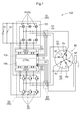
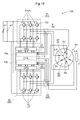
- the block diagram of FIG. 1 schematically shows the system configuration of the rotary electric machine control system 100.
- the rotary electric machine control system 100 controls an AC rotary electric machine 80 having two N-phase (N is a natural number) coil set 8 (first coil set 81 and second coil set 82).
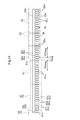
- the rotary electric machine 80 to be driven by the rotary electric machine control system 100 includes a stator 80s in which two coil sets 8 are arranged on the same stator core (see FIGS. 2 and 15) and a rotor 80r in which a permanent magnet 80 m is arranged on the rotor core. It is a permanent magnet type rotary electric machine (PMSM: Permanent Magnet Synchronous Motor) having (see FIG. 15).
- PMSM Permanent Magnet Synchronous Motor
- the first coil set 81 and the second coil set 82 have neutral three-phase stator coils (U-phase coil 8u, V-phase coil 8v, W-phase coil 8w), respectively. It is composed of a star connection (Y-shaped connection) short-circuited at a point NP.
- the rotary electric machine 80 can function as both an electric motor and a generator.
- the rotary electric machine control system 100 includes a DC power supply 41 and two inverters 50 connected to each coil set 8 to convert electric power between DC and N-phase alternating current.
- the rotary electric machine control system 100 is connected to the DC power supply 41 and the first coil set 81 to supply electric power between the DC and the N-phase (here, three-phase) alternating current. It includes a first inverter 51 for conversion, and a second inverter 52 connected to a DC power supply 41 and a second coil set 82 to convert power between DC and N-phase (here, three-phase) alternating current. .. That is, the rotary electric machine control system 100 includes two inverters 50 corresponding to the two coil sets 8. As shown in FIG.
- the first inverter 51 and the second inverter 52 are inverters 50 having different specifications (the same circuit configuration and different electrical specifications). As will be described later, each inverter 50 is switched and controlled at different timings so that currents having different phases flow through the first coil set 81 and the second coil set 82. Therefore, the two inverters 50 convert electric power between the direct current power supply 41 and the rotary electric machine 80 between the direct current and the alternating current of the 2N phase (here, 6 phases).
- the DC power supply 41 is composed of, for example, a rechargeable secondary battery (battery) such as a lithium ion battery, an electric double layer capacitor, or the like.
- the DC power supply 41 is a large-voltage, large-capacity DC power supply, and the rated power supply voltage is, for example, 200 to 400 [V].
- the DC side of the inverter 50 is provided with a smoothing capacitor (DC link capacitor 42) that smoothes the voltage between the positive electrode and the negative electrode (DC link voltage “Vdc”).
- Each inverter 50 is configured to have a plurality of switching elements 5.
- Each switching element 5 is provided with a freewheel diode 5D in parallel with the direction from the negative electrode to the positive electrode (the direction from the lower side to the upper side) as the forward direction.
- the switching element 5 includes Si-IGBT (Insulated Gate Bipolar Transistor) based on silicon (Si), Si-MOSFET (Metal Oxide Semiconductor Field Effect Transistor), and SiC-MOSFET based on silicon carbide (SiC).
- Power semiconductor elements such as (Silicon Carbide-Metal Oxide Semiconductor FET), SiC-SIT (SiC-Static Induction Transistor), SiC-IGBT, and GaN-MOSFET (Gallium Nitride-MOSFET) based on gallium nitride (GaN) Used.
- a general Si-IGBT is used for the second inverter 52, and the first inverter 51 uses the second inverter for the transition time between the off state and the on state. It illustrates a mode in which a SiC-MOSFET is used, which is shorter than a constituent switching element (Si-IGBT) and has a small switching loss.
- Si-IGBT silicon-IGBT based on silicon
- SiC silicon carbide
- GaN gallium nitride
- Semiconductor materials such as SiC and GaN have a wider bandgap than Si (wide bandgap semiconductor) and have a higher dielectric breakdown strength than Si, and have higher basic performance as a material for semiconductor materials than Si.
- the thickness of the drift layer of a high withstand voltage element for electric power (power switching element) using SiC or GaN as a base material can be made thinner than that of an element using Si as a base material. Since most of the resistance components of the high withstand voltage element for electric power are caused by the thickness of this drift layer, the high withstand voltage element for electric power using SiC or GaN as a base material has a higher per unit area than the element with a Si base material. It is possible to realize an element with very low on-resistance.
- IGBTs Si-IGBTs
- Si-IGBTs Si-IGBTs
- the IGBT is a switching element having an FET structure in the input stage and a bipolar transistor structure in the output stage on one semiconductor element.
- the IGBT has a larger switching loss than the MOSFET, for example, and is affected by the heat generated as a result, so that switching at a high frequency is limited.
- a high withstand voltage element for electric power using SiC or GaN as a base material has a thin drift layer as described above, so that it has a high-speed device structure, and even a MOSFET structure which is a large number of carrier devices can have a high withstand voltage.
- the accompanying increase in on-resistance can be suppressed. That is, a high withstand voltage element for electric power using SiC or GaN as a base material can realize high withstand voltage, low on-resistance, and high frequency operation.
- SiC-MOSFET is capable of higher speed switching and can be used at a higher switching frequency. Further, the loss of the inverter 50 can be expected to be reduced.
- SiC and GaN are more expensive than Si, and may increase the cost of the rotary electric machine control system 100 including the inverter 50 and the inverter 50.
- Each inverter 50 includes a plurality of sets (three sets in this case) of AC one-phase units composed of a series circuit of the upper switching element 5H and the lower switching element 5L.
- a bridge circuit is configured in which a set of series circuits (arms) correspond to each of the stator coils (8u, 8v, 8w) corresponding to the U phase, V phase, and W phase of each coil set 8.
- the intermediate point of the arm that is, the connection point between the upper switching element 5H and the lower switching element 5L is the stator coil (8u, 8v, 8w) corresponding to the U phase, V phase, and W phase of each coil set 8. Are connected to each.
- each inverter 50 is controlled by the inverter drive device 30.
- the inverter drive device 30 includes an inverter control device 10 (CTRL) and a drive circuit 20 (DRV).
- CTRL inverter control device
- DUV drive circuit 20
- the inverter control device 10 includes a first control unit 10a for controlling the first inverter 51 and a second control unit 10b for controlling the second inverter 52.
- the switching control signals of the 1 inverter 51 and the 2nd inverter 52 are independently generated to control the 1st inverter 51 and the 2nd inverter 52.
- a first drive circuit 21 is provided for the first inverter 51 and the first control unit 10a
- a second drive circuit 22 is provided for the second inverter 52 and the second control unit 10b.
- the inverter control device 10 is constructed with a processor such as a microcomputer as a core member.
- the inverter control device 10 is a target torque (torque command T * : FIG.) of the rotary electric machine 80 provided as a request signal from another control device such as a vehicle control device (not shown) which is one of the upper control devices. 19), current feedback control using the vector control method is performed, and the rotary electric machine 80 is controlled via the inverter 50.
- the actual current (Iu, Iv, Iw) flowing through the rotary electric machine is set to the d-axis, which is the direction of the magnetic field (magnetic flux) generated by the permanent magnet 80m arranged in the rotor 80r.
- the feedback control is performed by converting the coordinates to the vector components (Id, Iq) with the q-axis in the direction orthogonal to the d-axis (direction advanced by ⁇ / 2 by the electric angle with respect to the direction of the magnetic field).
- Ia indicates the combined current which was vector-combined.
- the inverter drive device 30 (inverter control device 10) has a current command (I * ) based on the torque command T * of the rotary electric machine 80 and an actual current command (I * ) in the dq-axis orthogonal vector coordinate system.
- the rotary electric machine 80 is feedback-controlled based on the deviation from the current.
- the actual current flowing through the rotary electric machine 80 is detected by two current sensors 6 (SEN-I), and the inverter control device 10 acquires the detection result.
- the first current sensor 61 that detects the alternating current of each phase flowing through the first coil set 81
- the second current sensor 62 that detects the alternating current of each phase flowing through the second coil set 82 are provided.
- FIG. 1 illustrates a mode in which the current sensor 6 detects alternating current of all phases. For example, in the case of three-phase alternating current, the three phases are balanced and the sum of their instantaneous values is zero. Therefore, the current of only two phases may be detected and the remaining one phase may be acquired by the inverter control device 10 by calculation.
- the magnetic pole positions (electrical angle ⁇ : see FIGS. 15 and 19) and the rotational speed of the rotor 80r (angular velocity ⁇ (see FIG. 19)) of the rotor 80r of the rotary electric machine 80 at each time point are determined.
- a rotation sensor 7 such as a resolver
- the inverter control device 10 acquires the detection result.
- the inverter control device 10 executes current feedback control using the detection results of the current sensor 6 and the rotation sensor 7.
- each switching element 5 constituting the inverter 50 The control terminals (for example, the gate terminals of IGBTs and FETs) of each switching element 5 constituting the inverter 50 are connected to the inverter control device 10 via the drive circuit 20, and each switching element 5 is individually switched and controlled.
- the inverter control device 10 that generates a switching control signal is configured with a microcomputer or the like as the core, and its operating voltage is, for example, 5 [V], 3.3 [V], 2.5 [V]. And so on.
- the inverter 50 is connected to a DC power supply 41 having a rated power supply voltage of, for example, 200 to 400 [V], and the control terminal of the switching element 5 is driven by, for example, 15 to 20 [V].
- the drive circuit 20 enhances the driving ability of the switching control signal generated by the inverter control device 10 (for example, the ability to operate a subsequent circuit such as voltage amplitude and output current) and relays the switching control signal to the inverter 50.
- FIG. 2 shows the stator coil (81u, 81v, 81w) of the first coil set 81 and the stator coil (82u, 82v,) of the second coil set 82 wound in the slot 8s formed in the stator 80s of the rotary electric machine 80.
- An arrangement example of 82w) is shown. This corresponds to the 6-phase (2N phase) alternating current as described above.
- the stator coils include the first U-phase coil 81u of the first coil set 81, the second U-phase coil 82u of the second coil set 82, the first V-phase coil 81v of the first coil set 81, and the second coil.
- the second V-phase coil 82v of the set 82, the first W-phase coil 81w of the first coil set 81, and the second W-phase coil 82w of the second coil set 82 are repeatedly arranged in this order. Since the stator coil of the first coil set 81 (first system) and the stator coil of the second coil set 82 (second system) are adjacent to each other, there is mutual inductance between the systems.
- the in-phase coils of the first coil set 81 are arranged 180 degrees apart in terms of electrical angle.
- the in-phase coils of the second coil set 82 are also arranged 180 degrees apart in terms of electrical angle.
- the first coil set 81 and the second coil set 82 are arranged at an electrical angle of 30 degrees apart.
- the 1st U phase coil 81u and the 2nd U phase coil 82u, the 1st V phase coil 81v and the 2nd V phase coil 82v, and the 1st W phase coil 81w and the 2nd W phase coil 82w are arranged 30 degrees apart in terms of electrical angle. There is.
- the inverter control device 10 generates a switching control signal that individually controls each of the first inverter 51 and the second inverter 52 so that currents having different phases flow through the first coil set 81 and the second coil set 82.
- the first inverter 51 and the second inverter 52 are controlled.
- FIG. 20 illustrates a rotary electric machine control system 100 as a comparative example with respect to FIG. 1, and FIG. 21 shows an arrangement example of a stator coil as a comparative example with respect to FIG.
- each inverter 50 is switched and controlled at the same timing, and power is transferred between the DC power supply 41 and the rotary electric machine 80, and between the DC and the N-phase (here, three-phase) AC. Will be converted.
- the first coil set 81 includes a first U phase coil 81u, two first V phase coils 81v, two first W phase coils 81w, and a first U phase coil 81u as a set, and here, four times.
- the second coil set 82 is repeatedly arranged, and subsequently, the second coil set 82 is repeated four times in the same manner with the second U-phase coil 82u, the two second V-phase coils 82v, the two second W-phase coils 82w, and the second U-phase coil 82u as one set. It is arranged.
- the stator coil of the first coil set 81 (first system) and the stator coil of the second coil set 82 (second system) are not adjacent to each other except for a part of the U phase, they are mutual to each other. There is almost no inductance.
- FIG. 5 shows the distribution of harmonic components of the magnetomotive force.
- the magnetomotive force due to the 6-phase alternating current has less harmonic components of the 5th and 7th orders than the magnetomotive force due to the 3-phase alternating current. As a result, iron loss is reduced.
- FIG. 6 shows the ratio of the harmonic component to the primary component of the line back electromotive voltage. It can be seen that when the rotary electric machine 80 is driven by a 6-phase alternating current, the 5th harmonic component and the 7th harmonic component are particularly large as compared with the case where the rotary electric machine 80 is driven by a 3-phase alternating current.
- the waveform diagram of FIG. 7 shows an example of the counter electromotive voltage when the rotary electric machine 80 is driven by 6-phase AC
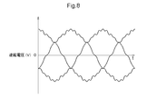
- the waveform diagram of FIG. 8 shows the counter electromotive force when the rotary electric machine 80 is driven by 3-phase AC.
- An example of voltage is shown.
- the counter electromotive voltage is higher than that when the rotary electric machine 80 is driven by 3-phase AC due to the 5th harmonic component and the 7th harmonic component as described above.
- the distortion of the waveform of is large.
- the stator coil of the first coil set 81 (first system) and the stator coil of the second coil set 82 (second system) are adjacent to each other. There is a mutual inductance in. This mutual inductance contributes to the distortion of the back electromotive voltage waveform. This distortion is a harmonic component and causes electromagnetic noise and audible noise.
- the following equation (1) shows the three-phase voltage equation of the first coil set 81
- the equation (2) shows the three-phase voltage equation of the second coil set 82
- the following equation (3) shows the two-phase voltage equation of the first coil set 81
- the equation (4) shows the two-phase voltage equation of the second coil set 82.
- the subscripts of "u, v, w” indicate the U phase, V phase, and W phase, respectively
- the subscripts of "d, q” indicate the d axis and q axis, respectively
- the subscripts of "a" Subscripts indicate the entire (three-phase synthesis) of each of the first coil set 81 and the second coil set 82.
- R is the resistance component of the coil set 8
- L is the self-inductance of the stator coils (8u, 8v, 8w) of each phase
- M is the mutual inductance
- MI f is the electromotive force coefficient (torque). Coefficient) is shown.
- P is a differential operator.
- FIG. 9 shows an example of a 6-phase current waveform controlled and generated by the inverter control device 10.
- the cutoff frequency of the inverter control device 10 current control unit 12 (see FIG. 19) described later
- the gain in the feedback control is increased
- the target (command) is reached quickly in principle. ..
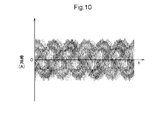
- the cutoff frequency is increased and the feedback gain is increased, the control does not converge and the current control may not be possible.
- the waveform shown in FIG. 10 illustrates a state in which control has not converged.
- the waveform of FIG. 11 having a high modulation frequency has smaller distortion than the waveform of FIG. 9 having a low cutoff frequency and a low feedback gain.
- the modulation frequency of the waveform of FIG. 11 is about twice that of the waveforms of FIGS. 9 and 10.
- the distortion of the counter electromotive voltage is smaller in the three-phase AC than in the six-phase AC
- the distortion of the AC current waveform is also smaller. Therefore, if only one inverter 50 is used and only one coil set 8 is energized with a three-phase alternating current, the cutoff frequency is increased to increase the feedback gain, and even if the modulation frequency is maintained, the figure is shown. As illustrated in 12, the feedback control can be converged. However, since the current flowing through the first coil set 81 and the second coil set 82 is passed through one coil set 8 (for example, only the first coil set 81), the effective value of the alternating current is doubled.
- FIG. 13 shows.
- the feedback control can be converged.
- one of the inverters 50 is sufficient to increase the modulation frequency. Therefore, as illustrated in FIG. 1, if the Si-IGBT is used as the switching element 5 only in the first inverter 51 and the Si-IGBT is used as the switching element 5 in the second inverter 52, the cost increases. It can be suppressed. That is, as shown in FIG. 17 of the comparative example, the cost of the inverter 50 can be reduced as compared with the form in which the SiC-MOSFET is used as the switching element 5 of both the first inverter 51 and the second inverter 52.
- the inverter control device 10 stops the second inverter 52 and controls the switching of the first inverter 51 to convert electric power between direct current and alternating current of N phase (here, three phases), or Both the first inverter 51 and the second inverter 52 are switched and controlled to convert electric power between direct current and alternating current of 2N phase (here, 6 phase). Further, it is preferable that the inverter control device 10 switches and controls the first inverter 51 at the first switching frequency and the second inverter 52 at a second switching frequency lower than the first switching frequency. As is clear from the comparison between FIGS. 11 and 13, the distortion of the waveform is smaller in FIG. That is, as shown in FIG.
- the cutoff frequency is cut-off frequency without increasing the modulation frequency.
- the feedback control can be converged in a state where the value is increased and the feedback gain is increased. That is, as shown in FIG. 18 of the comparative example, even when both the first inverter 51 and the second inverter 52 are composed of Si-IGBTs, it is possible to reduce the distortion of the waveform to some extent. is there. However, as is clear from the comparison between FIGS. 12 and 13, by driving the first inverter 51 with a signal modulated at a higher modulation frequency, a waveform with less distortion can be obtained.
- the rotary electric machine 80 which is a driving force source for a vehicle, is required to be driven by various torques such as starting, accelerating, climbing a slope, and cruising.
- a relatively large torque is required for starting, accelerating, and climbing a slope.
- the operating area of the rotary electric machine 80 is set so as to correspond to various operating conditions, but the frequently operating area is not an operating area that requires such a large torque. It is a relatively low torque and low rotation speed or intermediate rotation speed operating region.
- a first region R1 having a relatively low torque and a medium / low speed and a second region R2 on the higher torque side than the first region R1. And set.
- the inverter control device 10 stops the second inverter 52 and switches the first inverter 51 in the first region R1 of the operating regions of the rotary electric machine 80 defined by the torque and the rotation speed of the rotary electric machine 80. Then, the electric power is converted between the direct current and the alternating current of the N phase (here, three phases).
- the second region R2 which is a region on the higher torque side than the first region R1
- the first inverter 51 and the second inverter 52 are switched and controlled to switch between direct current and 2N phase (here, 6 phase) alternating current. Convert power between.
- first region R1 and the second region R2 in the operation region are illustrated by using the operation region of the rotary electric machine 80 based on the torque and the rotation speed as shown in FIG.
- first region R1 and the second region R2 are not limited to this form, and may be set based on, for example, the DC link voltage “Vdc” and the counter electromotive voltage.
- the inverter control device 10 switches the control mode between the state in which the second inverter 52 is stopped and the first inverter 51 is switched and controlled, and the state in which the first inverter 51 and the second inverter 52 are switched and controlled. become.
- the rotary electric machine 80 outputs the same torque.
- the inverter control device 10 when the operating region of the rotary electric machine 80 shifts from the first region R1 to the second region R2, the current flowing through the first coil set 81 while maintaining the output torque of the rotary electric machine 80.
- the first inverter 51 and the second inverter 52 are switched and controlled so that the current corresponding to the reduced current flows through the second coil set 82.
- FIG. 16 shows the operating points of the rotary electric machine 80 according to the currents (d-axis current, q-axis current) in the dq-axis Cartesian coordinate system.
- the symbol “L3” is a maximum efficiency line (three-phase maximum) indicating a vector locus of an operating point that outputs torque with the highest efficiency when the rotary electric machine 80 is driven by three-phase alternating current by switching control only the first inverter 51.
- Efficiency line indicates the operating point of one inverter 5 when torque is output with the highest efficiency when the rotary electric machine 80 is driven by 6-phase alternating current by switching control of the first inverter 51 and the second inverter 52. It is a maximum efficiency line (6-phase maximum efficiency line) showing a vector locus.
- the symbol “LT” is an equal torque line which is a vector locus of an operating point that outputs the same torque.
- the operating point of the rotary electric machine 80 is the first operating point P1, and from the state where only the first inverter 51 is switched controlled, the operating points where the first inverter 51 and the second inverter 52 are switched controlled.
- the case of transitioning to a certain third operating point P3 is illustrated.
- the inverter control device 10 reduces the current flowing through the first coil set 81 in the direction of the arrow Y1 along the three-phase maximum torque line L3 while maintaining the output torque of the rotary electric machine 80.
- the inverter control device 10 starts to flow a current corresponding to the decreasing current to the second coil set 82.
- the current flowing through the second coil set 82 rises in the direction of arrow Y2 along the three-phase maximum torque line L3.
- the operating point defined by the current flowing through the first coil set 81 and the second coil set 82 both approaches the second operating point P2 along the three-phase maximum efficiency line L3. Since the two operating points move in the direction of the arrow Y3 along the three-phase maximum torque line L3 from the position sandwiching the one operating point (second operating point P2), the operating points should be moved with high system efficiency. Can be done.
- the inverter control device 10 sets the equal torque line LT along the equal torque line LT.
- the operating point is moved to the third operating point P3 located at the intersection with the 6-phase maximum efficiency line L6. Since the operating point moves along the equal torque line LT, torque fluctuation does not occur except for a control error. Although detailed description is omitted, the same applies to the case where the operating point is moved from the third operating point P3 to the first operating point P1.
- the inverter control device 10 controls the control mode between the state in which the second inverter 52 is stopped and the first inverter 51 is switched and controlled, and the state in which the first inverter 51 and the second inverter 52 are switched and controlled. It can be switched smoothly.
- the inverter control device 10 switches and controls the first inverter 51 and the second inverter 52 so that currents having the same effective value flow through the first coil set 81 and the second coil set 82 in the second region R2.
- the feedback gain in the first region R1 is set to a value higher than the feedback gain in the second region R2.
- the two coil sets 8 are energized via the two inverters 50, disturbance is likely to occur due to the influence of the mutual inductance between the two coil sets 8, and the higher the feedback gain, the more the control converges. It becomes difficult.
- the system efficiency is improved by using a feedback gain having a value higher than the feedback gain in the feedback control in the second region R2. Can be made to.
- the inverter control device 10 is configured to have various functional units for current feedback control, and each functional unit includes hardware such as a microcomputer and software (program). It will be realized by the collaboration of.
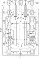
- the inverter control device 10 includes a current command calculation unit 11, a current control unit 12, a voltage control unit 13, a modulation unit 14, and a three-phase two-phase coordinate conversion unit 15.
- the inverter control device 10 includes a first control unit 10a whose control target is the first inverter 51, and a second control unit 10b whose control target is the second inverter 52.
- the current control unit 12, the voltage control unit 13, the modulation unit 14, and the three-phase two-phase coordinate conversion unit 15 are functional units (first current control unit 12a, first voltage control unit 13a,) included in the first control unit 10a.
- the current command calculation unit 11, the torque command T *, the torque command distribution unit for distributing the first torque command T * 1 with respect to the first control unit 10a to the second torque command T * 2 to the second control unit 10b 1st current command calculation to calculate 110 (DIV) and 1st current command I * 1 (1st d-axis current command I * d1 , 1st q-axis current command I * q1 ) based on 1st torque command T * 1.
- Second current command calculation unit 11b that calculates the second current command I * 2 (second d-axis current command I * d2 , second q-axis current command I * q2 ) based on the second torque command T * 2 and unit 11a. And have.
- the inverter control device 10 has a first current command (I * d1 , I * q1 ) and a first current command (I * d1 , I * q1 ), which are current commands of the first coil set 81, which are set based on the target torque (torque command T * ) of the rotary electric machine 80.
- the first inverter 51 is switched and controlled based on the deviation from the current ( Id1 , I q1 ) flowing through the coil set 81, and the second coil is set based on the target torque (torque command T * ) of the rotary electric machine 80.
- the rotary electric machine 80 is controlled by switching the second inverter 52 based on the deviation between the second current command I * 2 , which is the current command of the set 82, and the currents ( Id2 , Iq2 ) flowing through the second coil set 82.
- Current feedback control is controlled by switching the second inverter 52 based on the deviation between the second current command I * 2 , which is the current command of the set 82, and the currents ( Id2 , Iq2 ) flowing through the second coil set 82.
- the first control unit 10a will be described first, and then the second control unit 10b will be described. However, since the first control unit 10a and the second control unit 10b have basically the same structure, the same location will be described. May omit the description as appropriate.
- the two-phase current command (I * d1 , I * q1 ) and the actual current of the rotary electric machine 80 (U-phase current i u1ph , V-phase current i v1ph , W-phase current i w1ph ) are set.
- the first current control unit 12a includes a d-axis proportional integration control unit 121 (PI), a q-axis proportional integration control unit 122 (PI), a q-axis non-interference control unit 123 (CRS), and a d-axis non-interference control unit 124 (CRS). ) Is provided.
- the d-axis proportional integration control unit 121 performs the calculation as shown in the following equation (5) based on the deviation between the d-axis current command (I * d1 ) and the d-axis current ( Id1 ), and performs the q-axis proportional integration control.
- the unit 122 performs the calculation as shown in the following equation (6) based on the deviation between the q-axis current command (I * q1 ) and the q-axis current (I q1 ).
- a low cutoff frequency is set in order to suppress the influence of the disturbance voltage caused by the mutual inductance.
- the high cutoff frequency is about 2 to 2.5 times the low cutoff frequency.
- the q-axis non-interference control unit 123 performs the calculation as shown in the following equation (7) based on the deviation between the d-axis current command (I * d1 ) and the d-axis current ( Id1 ), and performs d-axis non-interference control.
- the unit 124 performs the calculation as shown in the following equation (8) based on the deviation between the q-axis current command (I * q1 ) and the q-axis current (I q1 ).
- the inverter control device 10 includes a feedforward calculation unit, and calculates a d-axis feedforward value (V d1 FF) and a q-axis feedforward value (V q1 FF). Has been done.
- the d-axis feedforward value (V d1 FF) and the q-axis feedforward value (V q1 FF) are represented by the following equations (9) and (10).
- the first current control unit 12a has a calculation result (V d1 FB) of the d-axis proportional integration control unit 121 and a calculation result (V d1 cross) of the d-axis non-interference control unit 124. And the separately calculated d-axis feedforward value (V d1 FF) are added to calculate the d-axis voltage command (V * d1 ).
- the first current controller 12a as shown in the following formula (14), the operation result of the q-axis proportional-integral controller 122 and (V q1 FB), the operation result of the q-axis non-interacting controller 123 (V q1 cross) and the separately calculated q-axis feedforward value (V q1 FF) are added to calculate the d-axis voltage command (V * q1 ).
- the first voltage control unit 13a calculates a three-phase voltage command corresponding to the first coil set 81 based on the two-phase voltage command (V * d1 , V * q1 ) of the dq-axis orthogonal vector coordinate system.
- the first voltage control unit 13a includes a voltage calculation unit 131 that calculates a two-phase voltage based on the DC link voltage “Vdc”, and a two-phase three-phase coordinate conversion unit 132 that converts a two-phase voltage into a three-phase voltage command. It has.
- the first modulation unit 14a generates a switching control signal of the first inverter 51 based on each of the three-phase voltage commands.
- a mode in which the first modulation unit 14a generates a switching control signal by pulse width modulation (PWM) based on the carrier of the first switching frequency is illustrated.
- the switching element 5 of the first inverter 51 is a SiC-MOSFET, which can switch at a higher switching frequency than the Si-IGBT. Therefore, it is preferable that the first switching frequency is a frequency higher than the second switching frequency (for example, about 2 to 2.5 times).
- the second current control unit 12b has a two-phase current command (I * d2 , I * q2 ) and the actual current of the rotary electric machine 80 (U-phase current i u2ph , V-phase current i v2ph , W-phase current i w2ph ). Based on the deviation from the coordinate-converted two-phase actual current ( Id2 , I q2 ), the two-phase voltage command (V * d2 , V * q2 ), which is the command of the voltage applied to the inverter 50, is calculated. .. As shown in FIG.
- the second current control unit 12b also has the same functional unit as the first current control unit 12a.
- the d-axis proportional integration control unit 121 performs the calculation as shown in the following equation (15) based on the deviation between the d-axis current command (I * d2 ) and the d-axis current ( Id2 ), and performs the q-axis proportional integration control.
- the unit 122 performs the calculation as shown in the following equation (16) based on the deviation between the q-axis current command (I * q2 ) and the q-axis current (I q2 ).
- the q-axis non-interference control unit 123 performs the calculation as shown in the following equation (17) based on the deviation between the d-axis current command (I * d2 ) and the d-axis current ( Id2 ), and performs d-axis non-interference control.
- the unit 124 performs the calculation as shown in the following equation (18) based on the deviation between the q-axis current command (I * q2 ) and the q-axis current (I q2 ).
- (I) Idq2 is the product of the rotational speed (angular velocity ⁇ ), the d-axis self-inductance L d2 , the control period [seconds], and the cutoff frequency, and is the product of equation (18).
- (I) Iqd2 is the product of the rotation speed (angular velocity ⁇ ), the q-axis self- inductivity L q2 , the control period [seconds], and the cutoff frequency.
- the inverter control device 10 includes a feedforward calculation unit, and calculates a d-axis feedforward value (V d2 FF) and a q-axis feedforward value (V q2 FF). Has been done.
- the d-axis feedforward value (V d2 FF) and the q-axis feedforward value (V q2 FF) are represented by the following equations (19) and (20).
- the second current control unit 12b has a calculation result (V d2 FB) of the d-axis proportional integration control unit 121 and a calculation result (V d2 cross) of the d-axis non-interference control unit 124. And the separately calculated d-axis feedforward value (V d2 FF) are added to calculate the d-axis voltage command (V * d2 ).
- the second current controller 12b as shown in the following formula (24), the operation result of the q-axis proportional-integral controller 122 and (V q2 FB), the operation result of the q-axis non-interacting controller 123 (V q2 cross) and the separately calculated q-axis feed forward value (V q2 FF) are added to calculate the d-axis voltage command (V * q2 ).
- Three-phase actual current of the second coil set 82 coordinate transformation (U-phase current i u2ph, V-phase current i v2ph, W-phase current i w2ph) from the actual current of the two-phase (I d2, I q2) is It is executed by the three-phase two-phase second coordinate conversion unit 15b.
- the three-phase two-phase second coordinate conversion unit 15b performs coordinate conversion based on the rotation position (magnetic pole position, electric angle ⁇ ) of the rotor 80r detected by the rotation sensor 7 (SEN-R) at each time point.
- the first coil set 81 and the second coil set 82 are controlled so that currents having different phases of 30 degrees ( ⁇ / 6) flow.
- the second electric angle ⁇ 2 used in the coordinate conversion in the three-phase two-phase second coordinate conversion unit 15b is 30 degrees with the first electric angle ⁇ 1 used in the coordinate conversion in the three-phase two-phase first coordinate conversion unit 15a. ( ⁇ / 6)
- the phase is different.
- the second electric angle ⁇ 2 is “ ⁇ / 6” whose phase is delayed by 30 degrees ( ⁇ / 6) from the electric angle ⁇ detected by the rotation sensor 7.
- the second voltage control unit 13b calculates a three-phase voltage command corresponding to the second coil set 82 based on the two-phase voltage command (V * d1 , V * q1 ) of the dq-axis orthogonal vector coordinate system.
- the second voltage control unit 13b includes a voltage calculation unit 131 that calculates a two-phase voltage based on the DC link voltage “Vdc”, and a two-phase three-phase coordinate conversion unit 132 that converts a two-phase voltage into a three-phase voltage command. It has.
- the second modulation unit 14b generates a switching control signal for the second inverter 52 based on each of the three-phase voltage commands.
- a mode in which the second modulation unit 14b generates a switching control signal by pulse width modulation based on the carrier of the second switching frequency is illustrated.
- the switching element 5 of the first inverter 51 is a SiC-MOSFET, which can switch at a higher switching frequency than the Si-IGBT. Therefore, as described above, it is preferable that the first switching frequency is higher than the second switching frequency (for example, about 2 to 2.5 times). In addition, the first inverter 51 may be driven independently, in which case it is preferable that the switching frequency is higher, as described above with reference to FIGS. 11 and 13.
- rotation in which an N-phase (N is a natural number) first coil set (81) and an N-phase second coil set (82) control an alternating current rotary electric machine (80) arranged on the same stator core.
- the electric control system (100) includes a first inverter (51) connected to a direct current power supply (41) and the first coil set (81) to convert power between direct current and N-phase alternating current, and the direct current.
- a second inverter (52) connected to a power supply (41) and the second coil set (82) to convert power between direct current and N-phase alternating current, the first inverter (51), and the second.
- a switching control signal for individually controlling each of the inverters (52) is generated so that currents having different phases flow through the first coil set (81) and the second coil set (82). (51) and an inverter control device (10) for controlling the second inverter (52) are provided, and the inverter control device (10) stops the second inverter (52) and the first inverter (10). 51) is switched and controlled to convert power between direct current and N-phase alternating current, or both the first inverter (51) and the second inverter (52) are switched and controlled to produce direct current.
- the switching element (5) constituting the first inverter (51) has a transition time between the off state and the on state of the second inverter, which converts electric current between the two N-phase alternating currents. It is shorter than the switching element constituting (52) and has a small switching loss.
- the load of the inverter (50) is provided by providing two inverters (50) corresponding to the two coil sets (8).
- the purpose is to increase the torque of the rotary electric machine (80) by making it possible to pass a larger alternating current.
- the second coil set (52) the iron loss caused by the mutual inductance is also suppressed.
- the 2N phase alternating current can be passed through the rotary electric machine (80), so that the N phase alternating current can be passed.
- the output torque can be increased as compared with the case where the electric current is passed through the rotary electric machine (80). That is, according to this configuration, it is possible to switch the control mode between the control using one inverter (50) and the control using two inverters (50) as needed. In this case, the first inverter (51) that operates independently will always operate, but the second inverter (52) may stop.
- the switching element (5) constituting the first inverter (51) having a higher operating rate is an element having a smaller switching loss than the switching element (5) constituting the second inverter (52), the entire system The loss can be reduced.
- a switching element (5) having such a small switching loss is expensive. Therefore, by using it only for the first inverter (51), which is one of the two inverters (50), the cost of the entire system is reduced. Can be suppressed from increasing. That is, according to this configuration, in a system for controlling an AC rotary electric machine (80) equipped with two coil sets (8), it is possible to improve system efficiency while suppressing an increase in system cost. ..
- the inverter control device (10) controls switching of the first inverter (51) at a first switching frequency, and switches the second inverter (52) at a second switching frequency lower than the first switching frequency. It is preferable to control it.
- the switching element (5) constituting the first inverter (51) is an element having a shorter transition time between the off state and the on state than the switching element constituting the second inverter (52) and having a small switching loss. is there. Therefore, the switching element constituting the first inverter (51) can operate more efficiently even at a higher switching frequency than the switching element constituting the second inverter (52). Therefore, the system efficiency can be improved by controlling the switching of the first inverter (51) at the first switching frequency and controlling the switching of the second inverter (52) at the second switching frequency lower than the first switching frequency. it can.
- the inverter control device (10) has the second inverter in the first region (R1) of the operating regions of the rotary electric machine (80) defined by the torque and the rotation speed of the rotary electric power (80). (52) is stopped and the first inverter (51) is switched and controlled to convert electric power between direct current and N-phase alternating current, and in a region on the higher torque side than the first region (R1). In a certain second region (R2), it is preferable to control the switching of the first inverter (51) and the second inverter (52) to convert electric power between direct current and alternating current of 2N phase.
- the most frequent operating region of the rotary electric machine (80) is often the region on the relatively low torque side.
- one of the advantages of the rotary electric machine (80) having two coil sets (8) is that it is provided with two inverters (50) corresponding to the two coil sets (8). The purpose is to reduce the load of (50) and increase the torque of the rotary electric machine (80) by passing a larger alternating current.
- the inverter control device (10) uses the second inverter (52). It is stopped and the first inverter (51) is switched and controlled to convert electric power between direct current and alternating current of N phase.
- the iron loss in the first region (R1) which is considered to be the most frequent in the operating region of the rotary electric machine (80), is reduced, so that the system efficiency can be improved.
- the inverter control device (10) switches and controls the first inverter (51) and the second inverter (52) to switch between direct current and 2N phase alternating current. Since the electric power is converted between the two, the torque required for the rotary electric machine (80) can be output. In this case, iron loss due to mutual inductance occurs.
- the inverter control device (10) uses the first inverter so that currents having different phases ( ⁇ / 2N) flow through the first coil set (81) and the second coil set (82). It is preferable to control (51) and the second inverter (52).
- the inverter control device (10) individually switches and controls the first inverter (51) and the second inverter (52) to appropriately transfer power between direct current and 2N phase alternating current. It can be converted.
- first region (R1) and the second region (R2) are set based on the torque and the rotation speed of the rotary electric machine (80), or the first inverter (51) and the said. It is preferable that the voltage is set based on the voltage on the DC side of the second inverter (52) and the countercurrent voltage of the rotary electric machine (80).
- the operating range of the rotary electric machine (80) can be defined by the relationship between the torque and the rotation speed, the relationship between the voltage on the DC side of the inverter (50) and the counter electromotive voltage, and the like. Then, in such an operating area, it is possible to specify an operating area that is relatively frequently used and an operating area that is used infrequently. Therefore, when the first region (R1) and the second region (R2) are set as described above, the electric power is appropriately converted by using both the first inverter (51) and the second inverter (52). A control mode and a control mode in which the second inverter (52) is stopped and the electric power is converted only by the first inverter (51) can be selected.
- the inverter control device (10) outputs the output of the rotary electric machine (80) when the operating region of the rotary electric machine (80) shifts from the first region (R1) to the second region (R2).
- the first inverter (51) reduces the current flowing through the first coil set (81) while maintaining the torque, and causes a current corresponding to the reduced current to flow through the second coil set (82).
- the second inverter (52) are preferably controlled by switching.
- the first coil set (81) and the second coil set (82) are connected so that currents having the same effective value flow through the first coil set (81). It is preferable to control the switching of the 1 inverter (51) and the 2nd inverter (52).
- the inverter control device (10) is a first current command (I) which is a current command of the first coil set (81) set based on the target torque (T * ) of the rotary electric machine (80).
- the first inverter (51) is switched and controlled based on the deviation between the current ( Id1 , I q1 ) flowing through the first coil set (81) and the * d1 , I * q1 ), and the rotary electric machine (80) is controlled.
- the second current command (I * d2 , I * q2 ) and the second coil set (82), which are the current commands of the second coil set (82), are set based on the target torque (T * ) of).
- the second inverter (52) is switched and controlled based on the deviation from the flowing current ( Id2 , Iq2 ), and the rotating electric machine (80) is current feedback controlled.
- the first region (R1) It is preferable that the feedback gain in is set to a value higher than the feedback gain in the second region (R2).
- Switching element 10 Inverter control device 41: DC power supply 51: First inverter 52: Second inverter 80: Rotating electric machine 81: First coil set 82: Second coil set 100: Rotating electric current control system I * d1 , I * Q1 : First current command I * d2 , I * q2 : Second current command I d1 , I q1 : Current flowing through the first coil set I d2 , I q2 : Current flowing through the second coil set R1: First region R2: Second region T * : Target torque
Landscapes
- Engineering & Computer Science (AREA)
- Power Engineering (AREA)
- Control Of Ac Motors In General (AREA)
- Inverter Devices (AREA)
Abstract
N相の2つのコイルセット(8)が同一のステータコアに配置された交流の回転電機80を制御する回転電機制御システム100は、第1インバータ(51)と、第2インバータ(52)と、2つのコイルセット(8)のそれぞれに異なる位相の電流が流れるように、それら2つのインバータ(50)をそれぞれ個別に制御するインバータ制御装置(10)とを備える。インバータ制御装置(10)は、第2インバータ(52)を停止させると共に第1インバータ(51)をスイッチング制御して直流とN相の交流との間で電力を変換させる、又は、2つのインバータ(50)をスイッチング制御して直流と2N相の交流との間で電力を変換させる。第1インバータ(51)を構成するスイッチング素子(5)は、オフ状態とオン状態との間での遷移時間が第2インバータ(52)を構成するスイッチング素子(5)よりも短く、スイッチング損失が小さい。
Description
本発明は、複数のコイルセットを備えた交流の回転電機を制御対象とする回転電機制御システムに関する。
特開2018-130007号公報には、複数のコイルセットとしての複数系統のステータ巻線(180,280)を備えた回転電機(80)を制御する回転電機制御装置(10)が開示されている(背景技術において括弧内の符号は参照する文献のもの。)。この回転電機制御装置(10)は、2系統のステータ巻線(180,280)に位相が30度ずれた相電流が通電されるように制御する(「位相差通電」と称す。)。位相差通電を行うと位相差通電を行わない場合に比べて出力トルクが向上すると共に、高調波のトルクリップルも低減され、騒音や振動も軽減される。
但し、当該文献では明示されていないが、このような位相差通電を行う場合、それぞれのコイルセットのステータ巻線が隣接して配置されることになる。従って、隣接するステータ巻線同士の相互インダクタンスが無視できなくなる。そして、この相互インダクタンスにも関連して、隣接するステータ巻線間の線間起電力の影響も大きくなる。特に、インバータのスイッチング周波数が低い場合には、低周波数の電流高調波(例えば5次高調波、7次高調波)と、スイッチング周波数の高調波の双方により、回転電機の鉄損を増加させ、システム効率を低下させる。例えば、インバータのスイッチング周波数を高くすることで、対応することも考えられるが、より高いスイッチング周波数に対応可能なスイッチング素子を用いる必要があり、システムコストを増大させる可能性がある。
上記背景に鑑みて、2つのコイルセットを備えた交流の回転電機を制御対象とするシステムにおいて、システムコストの増大を抑制しつつ、システム効率を向上させることが望まれる。
上記に鑑みた回転電機制御システムは、1つの態様として、N相(Nは自然数)の第1コイルセット及びN相の第2コイルセットが同一のステータコアに配置された交流の回転電機を制御する回転電機制御システムであって、直流電源及び前記第1コイルセットに接続されて直流とN相の交流との間で電力を変換する第1インバータと、前記直流電源及び前記第2コイルセットに接続されて直流とN相の交流との間で電力を変換する第2インバータと、前記第1インバータ及び前記第2インバータのそれぞれを個別に制御するスイッチング制御信号を生成して、前記第1コイルセット及び前記第2コイルセットにそれぞれ異なる位相の電流が流れるように前記第1インバータ及び前記第2インバータを制御するインバータ制御装置と、を備え、前記インバータ制御装置は、前記第2インバータを停止させると共に前記第1インバータをスイッチング制御して、直流とN相の交流との間で電力を変換させる、又は、前記第1インバータ及び前記第2インバータの双方をスイッチング制御して、直流と2N相の交流との間で電力を変換させるものであり、前記第1インバータを構成するスイッチング素子は、オフ状態とオン状態との間での遷移時間が前記第2インバータを構成するスイッチング素子よりも短く、スイッチング損失が小さい。
2つのコイルセットを備えた回転電機の利点の1つは、2つのコイルセットに対応して2つのインバータを備えることで、各インバータの負荷を低減し、より大きい交流電流を流すことを可能として回転電機のトルクを増大させることにある。しかし、要求トルクによっては、1つのインバータで対応可能な交流電流により回転電機に必要なトルクを出力させることも可能である。第2インバータを停止させると共に第1インバータをスイッチング制御した場合、第2コイルセットには第2インバータから電流が供給されないため、第1コイルセットと第2コイルセットとの相互インダクタンスに起因する鉄損も抑制される。一方、例えば要求トルクが高く、2つのインバータで対応すべき交流電流が必要な場合には、2N相の交流電流を回転電機に流すことができるので、N相の交流電流を回転電機に流す場合に比べて出力トルクを高くすることができる。即ち、本構成によれば、必要に応じて、1つのインバータを用いる制御と、2つのインバータを用いる制御とで、制御形態を切り替えることが可能である。この場合、単独で動作する第1インバータは常に動作することになるが、第2インバータは停止する場合がある。より稼働率の高い第1インバータを構成するスイッチング素子が、第2インバータを構成するスイッチング素子に比べてスイッチング損失が小さい素子であると、システム全体の損失を低減させることができる。一般的に、そのようにスイッチング損失が小さいスイッチング素子は高価であるから、2つのインバータの内の一方である第1インバータのみに用いることで、システム全体のコストの増加を抑制することができる。即ち、本構成によれば、2つのコイルセットを備えた交流の回転電機を制御対象とするシステムにおいて、システムコストの増大を抑制しつつ、システム効率を向上させることができる。
回転電機制御システムのさらなる特徴と利点は、図面を参照して説明する実施形態についての以下の記載から明確となる。
以下、回転電機制御システムの実施形態を図面に基づいて説明する。回転電機制御システムは、例えば、車両の駆動力源となる回転電機を駆動制御する。図1のブロック図は、回転電機制御システム100のシステム構成を模式的に示している。回転電機制御システム100は、N相(Nは自然数)のコイルセット8を2個(第1コイルセット81と第2コイルセット82)を備えた交流の回転電機80を制御対象とする。2個のコイルセット8は、同じ仕様(同じ構成及び同じ電気的仕様)のコイルセット8であり、本実施形態では、共に3相(N=3)のコイルセット8である。
回転電機制御システム100による駆動対象の回転電機80は、同一のステータコアに2つのコイルセット8が配置されたステータ80s(図2,図15参照)と、ロータコアに永久磁石80mが配置されたロータ80r(図15参照)とを有する永久磁石型回転電機(PMSM:Permanent Magnet Synchronous Motor)である。本実施形態では、第1コイルセット81及び第2コイルセット82は、図1に示すように、それぞれ3相のステータコイル(U相コイル8u,V相コイル8v,W相コイル8w)が中性点NPで短絡されたスター結線(Y字結線)により構成されている。尚、回転電機80は、電動機としても発電機としても機能することができる。
回転電機制御システム100は、直流電源41及びそれぞれのコイルセット8に接続されて直流とN相の交流との間で電力を変換する2個のインバータ50を備えている。本実施形態では、図1に示すように、回転電機制御システム100は、直流電源41及び第1コイルセット81に接続されて直流とN相(ここでは3相)の交流との間で電力を変換する第1インバータ51と、直流電源41及び第2コイルセット82に接続されて直流とN相(ここでは3相)の交流との間で電力を変換する第2インバータ52とを備えている。つまり、回転電機制御システム100は、2つのコイルセット8に対応して、2つのインバータ50を備えている。図1に示すように、第1インバータ51と、第2インバータ52とは、異なる仕様(回路構成は同一で異なる電気的仕様)のインバータ50である。尚、後述するように、それぞれのインバータ50は、第1コイルセット81及び第2コイルセット82にそれぞれ異なる位相の電流が流れるように、それぞれ異なるタイミングでスイッチング制御される。このため、2つのインバータ50により、直流電源41と回転電機80との間で、直流と2N相(ここでは6相)の交流との間で電力が変換される。
直流電源41は、例えば、リチウムイオン電池などの充電可能な二次電池(バッテリ)や、電気二重層キャパシタなどにより構成されている。回転電機80が、車両の駆動力源の場合、直流電源41は、大電圧大容量の直流電源であり、定格の電源電圧は、例えば200~400[V]である。インバータ50の直流側には、正極と負極との間の電圧(直流リンク電圧“Vdc”)を平滑化する平滑コンデンサ(直流リンクコンデンサ42)が備えられている。
それぞれのインバータ50は、複数のスイッチング素子5を有して構成される。各スイッチング素子5には、負極から正極へ向かう方向(下段側から上段側へ向かう方向)を順方向として、並列にフリーホイールダイオード5Dが備えられている。スイッチング素子5には、シリコン(Si)を基材としたSi-IGBT(Insulated Gate Bipolar Transistor)やSi-MOSFET(Metal Oxide Semiconductor Field Effect Transistor)、炭化ケイ素(SiC)を基材としたSiC-MOSFET(Silicon Carbide - Metal Oxide Semiconductor FET)やSiC-SIT(SiC - Static Induction Transistor)、SiC-IGBT、窒化ガリウム(GaN)を基材としたGaN-MOSFET(Gallium Nitride - MOSFET)などのパワー半導体素子が用いられる。図1には、スイッチング素子5として、第2インバータ52には一般的なSi-IGBTが用いられ、第1インバータ51には、オフ状態とオン状態との間での遷移時間が第2インバータを構成するスイッチング素子(Si-IGBT)よりも短く、スイッチング損失が小さい、SiC-MOSFETが用いられる形態を例示している。
従来、インバータ50のスイッチング素子5としては、ケイ素(Si)を基材としたSi-IGBTが広く利用されてきた。近年、電力用のMOSFETやIGBTの基材として、炭化ケイ素(SiC)や窒化ガリウム(GaN)などの半導体材料も実用化されてきている。SiCやGaNなどの半導体材料は、Siに比べてバンドギャップが広く(ワイドバンドギャップ半導体)、絶縁破壊強度もSiよりも高いなど、半導体材料の素材としての基本性能がSiよりも高い。絶縁破壊強度が高いことより、SiCやGaNを基材とする電力用高耐圧素子(パワースイッチング素子)では、ドリフト層の膜厚を、Siを基材とする素子よりも薄くすることができる。電力用高耐圧素子の抵抗成分の多くは、このドリフト層の厚みに起因するので、SiCやGaNを基材とする電力用高耐圧素子では、Si基材の素子と比べて、単位面積当たりのオン抵抗が非常に低い素子を実現できる。
Siを基材とする電力用高耐圧素子では、高耐圧化に伴うオン抵抗の増大を改善するために、少数キャリアデバイスであるバイポーラトランジスタの構造を備えたIGBT(Si-IGBT)が主流となっている。IGBTは、1つの半導体素子上において、入力段にFET構造を、出力段にバイポーラトランジスタ構造を持つスイッチング素子である。但し、IGBTは、例えばMOSFETに比べると、スイッチング損失が大きく、その結果として発生する熱の影響もあって、高周波数でのスイッチングには限界がある。SiCやGaNを基材とする電力用高耐圧素子では、上述したようにドリフト層が薄く構成できるので、高速なデバイス構造であり、多数キャリアデバイスであるMOSFET構造であっても、高耐圧化に伴うオン抵抗の増大を抑制することができる。つまり、SiCやGaNを基材とする電力用高耐圧素子は、高耐圧、低オン抵抗、高周波数動作を実現することができる。
例えば、Si-IGBTに比べて、SiC-MOSFETは、さらに高速スイッチングが可能であり、より高いスイッチング周波数での利用が可能である。また、インバータ50の損失の低減も期待できる。但し、SiCやGaNは、Siに比べて高価であり、インバータ50やインバータ50を含む回転電機制御システム100のコストを上昇させるおそれがある。
それぞれのインバータ50は、上段側スイッチング素子5Hと下段側スイッチング素子5Lとの直列回路により構成された交流1相分のアームを複数組(ここでは3組)備えている。本実施形態では、それぞれのコイルセット8のU相、V相、W相に対応するステータコイル(8u,8v,8w)のそれぞれに一組の直列回路(アーム)が対応したブリッジ回路が構成される。アームの中間点、つまり、上段側スイッチング素子5Hと下段側スイッチング素子5Lとの接続点は、それぞれのコイルセット8のU相、V相、W相に対応するステータコイル(8u,8v,8w)にそれぞれ接続される。
図1に示すように、それぞれのインバータ50は、インバータ駆動装置30により制御される。インバータ駆動装置30は、インバータ制御装置10(CTRL)とドライブ回路20(DRV)とを備えている。詳細は図19を参照して後述するが、インバータ制御装置10は、第1インバータ51を制御する第1制御部10aと第2インバータ52を制御する第2制御部10bとを備えており、第1インバータ51及び第2インバータ52のスイッチング制御信号をそれぞれ独立して生成して第1インバータ51及び第2インバータ52を制御する。そして、第1インバータ51及び第1制御部10aに対して第1ドライブ回路21が備えられ、第2インバータ52及び第2制御部10bに対応して第2ドライブ回路22が備えられている。
インバータ制御装置10は、マイクロコンピュータ等のプロセッサを中核部材として構築されている。例えば、インバータ制御装置10は、上位の制御装置の1つである不図示の車両制御装置等の他の制御装置等から要求信号として提供される回転電機80の目標トルク(トルク指令T*:図19参照)に基づいて、ベクトル制御法を用いた電流フィードバック制御を行って、インバータ50を介して回転電機80を制御する。図15に示すように、ベクトル制御法では、回転電機に流れる実電流(Iu,Iv,Iw)を、ロータ80rに配置された永久磁石80mが発生する磁界(磁束)の方向であるd軸と、d軸に直交する方向(磁界の向きに対して電気角でπ/2進んだ方向)のq軸とのベクトル成分(Id,Iq)に座標変換してフィードバック制御を行う。尚、“Ia”はベクトル合成された合成電流を示している。図19を参照して後述するように、インバータ駆動装置30(インバータ制御装置10)は、dq軸直交ベクトル座標系において、回転電機80のトルク指令T*に基づく電流指令(I*)と、実電流との偏差に基づいて回転電機80をフィードバック制御する。
図1に示すように、回転電機80(コイルセット8)を流れる実電流は2つの電流センサ6(SEN-I)により検出され、インバータ制御装置10はその検出結果を取得する。本実施形態では、第1コイルセット81に流れる各相の交流電流を検出する第1電流センサ61と、第2コイルセット82に流れる各相の交流電流を検出する第2電流センサ62とが備えられている。図1には、電流センサ6が、全相の交流電流を検出する形態を例示しているが、例えば3相交流の場合には3相は平衡しており、その瞬時値の和はゼロであるから2相のみの電流を検出して残りの1相はインバータ制御装置10が演算によって取得してもよい。
また、図1に示すように、回転電機80のロータ80rの各時点での磁極位置(電気角θ:図15、図19参照)やロータ80rの回転速度(角速度ω(図19参照))は、例えばレゾルバなどの回転センサ7(SEN-R)により検出され、インバータ制御装置10はその検出結果を取得する。インバータ制御装置10は、電流センサ6及び回転センサ7の検出結果を用いて、電流フィードバック制御を実行する。
インバータ50を構成する各スイッチング素子5の制御端子(例えばIGBTやFETのゲート端子)は、ドライブ回路20を介してインバータ制御装置10に接続されており、各スイッチング素子5はそれぞれ個別にスイッチング制御される。スイッチング制御信号を生成するインバータ制御装置10は、上述したように、マイクロコンピュータなどを中核として構成され、その動作電圧は、例えば5[V]、3.3[V]、2.5[V]等である。一方、インバータ50は、上述したように定格の電源電圧が例えば200~400[V]の直流電源41に接続されており、スイッチング素子5の制御端子には、例えば15~20[V]の駆動信号を入力する必要がある。ドライブ回路20は、インバータ制御装置10が生成したスイッチング制御信号の駆動能力(例えば電圧振幅や出力電流など、後段の回路を動作させる能力)をそれぞれ高めて、インバータ50に中継する。
図2は、回転電機80のステータ80sに形成されたスロット8sに巻き回された第1コイルセット81のステータコイル(81u,81v,81w)及び第2コイルセット82のステータコイル(82u,82v,82w)の配置例を示している。これは、上述したような6相(2N相)交流に対応したものである。図2に示すように、ステータコイルは、第1コイルセット81の第1U相コイル81u、第2コイルセット82の第2U相コイル82u、第1コイルセット81の第1V相コイル81v、第2コイルセット82の第2V相コイル82v、第1コイルセット81の第1W相コイル81w、第2コイルセット82の第2W相コイル82wの順に繰り返し配置されている。第1コイルセット81(第1系統)のステータコイルと第2コイルセット82(第2系統)のステータコイルとが隣接するため、系統間における相互インダクタンスが存在する。
第1コイルセット81の同相のコイルは、電気角で180度離れて配置されている。同様に第2コイルセット82の同相のコイルも、電気角で180度離れて配置されている。第1コイルセット81と第2コイルセット82とは、電気角で30度離れて配置されている。例えば、第1U相コイル81uと第2U相コイル82u、第1V相コイル81vと第2V相コイル82v、第1W相コイル81wと第2W相コイル82wは、それぞれ電気角で30度離れて配置されている。インバータ制御装置10は、第1コイルセット81及び第2コイルセット82にそれぞれ異なる位相の電流が流れるように、第1インバータ51及び第2インバータ52のそれぞれを個別に制御するスイッチング制御信号を生成して、第1インバータ51及び第2インバータ52を制御する。
図20は、図1に対する比較例の回転電機制御システム100を例示しており、図21は、図2に対する比較例としてのステータコイルの配置例を示している。図20に示すように、それぞれのインバータ50は、同じタイミングでスイッチング制御され、直流電源41と回転電機80との間で、直流とN相(ここでは3相)の交流との間で電力が変換される。図21に示すように、第1コイルセット81は、第1U相コイル81u、2つの第1V相コイル81v、2つの第1W相コイル81w、第1U相コイル81uを1組として、ここでは4回繰り返し配置され、続いて第2コイルセット82が、第2U相コイル82u、2つの第2V相コイル82v、2つの第2W相コイル82w、第2U相コイル82uを1組として、同様に4回繰り返し配置されている。この場合には、第1コイルセット81(第1系統)のステータコイルと第2コイルセット82(第2系統)のステータコイルとがU相の一部を除いて隣接しないため、系統間における相互インダクタンスがほとんど存在しない。
図20及び図21に示す比較例においては、第1コイルセット81と第2コイルセット82の同相のコイルには同じ位相の電流が流れる。例えば第1U相コイル81u同士、第2U相コイル82u同士は電気角で180度離れて配置されているが、第1U相コイル81u及び第2U相コイル82uには同じ位相の電流が流れるため、結果として、第1コイルセット81の同相コイル及び第2コイルセット82の同相コイルは、電気角で150度離れて配置されていることになる。また、例えば第1U相コイル81uと第2U相コイル82uとには、同じ位相の電流が流れるため、第1コイルセット81と第2コイルセット82とは、同じ電気角に配置されていることになる。
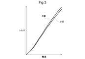
図3に示すように、回転電機80に6相交流を流して駆動した場合は、3相交流を流して駆動した場合に比べて同じ実効値の電流であっても大きなトルクが出力される。発明者らによる実験やシミュレーションによれば、3相交流に比べて6相交流では、電流が大きい側において概ね4%程度トルクが増加することが判った。回転速度との関係では、図4に示すように、相対的に回転速度が低い領域において、3相交流に比べて6相交流では、トルクが概ね2%増加し、高効率化することが判った。回転速度が高くなってくると3相交流の方が、トルクが大きくなっているがトルクの差は回転速度が低い領域よりも小さい。尚、回転速度が高い領域において、6相交流の方がトルクが小さくなるのは、図6~図8を参照して後述するように逆起電圧が関係していると考えられる。
図5は、起磁力の高調波成分の分布を示している。6相交流による起磁力は、3相交流による起磁力に比べて、5次、7次の高調波成分が少なくなっている。これにより、鉄損が低減される。
一方、図2を参照して上述したように、回転電機80を6相交流で駆動する場合には、位相の異なる電流が流れる第1コイルセット81のステータコイルと第2コイルセット82のステータコイルとが隣接している。このため、3相交流により回転電機80を駆動する場合と比べて、回転電機80を6相交流で駆動する場合には、線間逆起電圧の影響が大きくなる。図6は、線間逆起電圧の一次成分に対する高調波成分の割合を示している。回転電機80を6相交流で駆動する場合には、回転電機80を3相交流で駆動する場合に比べて、特に5次高調波成分、7次高調波成分が大きいことが判る。
図7の波形図は、回転電機80を6相交流で駆動した場合の逆起電圧の一例を示しており、図8の波形図は、回転電機80を3相交流で駆動した場合の逆起電圧の一例を示している。回転電機80を6相交流で駆動した場合、上述したような5次高調波成分、7次高調波成分に起因して、回転電機80を3相交流で駆動した場合に比べて、逆起電圧の波形の歪みが大きくなっている。上述したように、本実施形態におけるステータコイルの構成では、第1コイルセット81(第1系統)のステータコイルと第2コイルセット82(第2系統)のステータコイルとが隣接するため、系統間における相互インダクタンスが存在する。この相互インダクタンスが逆起電圧の波形の歪みの一因となっている。この歪みは、高調波成分であり、電磁ノイズや可聴ノイズの原因となる。
下記式(1)は、第1コイルセット81の3相電圧方程式を示し、式(2)は、第2コイルセット82の3相電圧方程式を示している。また、下記式(3)は、第1コイルセット81の2相電圧方程式を示し、式(4)は、第2コイルセット82の2相電圧方程式を示している。式中において、“u,v,w”の添え字は、それぞれU相、V相、W相を、“d,q”の添え字は、それぞれd軸、q軸を示し、“a”の添え字は、第1コイルセット81及び第2コイルセット82のそれぞれの全体(3相の合成)を示している。“R”はコイルセット8の抵抗成分であり、“L”は各相のステータコイル(8u,8v,8w)の自己インダクタンス、“M”は相互インダクタンス、“MIf”は起電力係数(トルク係数)を示している。“p”は微分演算子である。


詳細は図19を参照して後述するが、インバータ制御装置10は、上記式(1)~式(4)の電圧方程式に基づいて、電流フィードバック制御を実行してインバータ50をスイッチング制御する。図9は、インバータ制御装置10により制御されて生成された6相電流波形の一例を示している。電流フィードバック制御では、インバータ制御装置10(後述する電流制御部12(図19参照))のカットオフ周波数を高くしてフィードバック制御におけるゲインを高くすると、原理的には目標(指令)に速く到達する。しかし、相互インダクタンスなどに起因する、フィードバックループに対する外乱要素が存在する場合には、カットオフ周波数を高くしてフィードバックゲインを高くすると、制御が収束せず、電流制御できない場合がある。図10に示す波形は、制御が収束していない状態を例示している。
これは、インバータ制御装置10(後述する変調部14(図19参照))の変調周波数(キャリア周波数)を高くすることによって改善することができる。例えば、カットオフ周波数を高くしてフィードバックゲインを高くした状態(図10の波形が出力されるような状態)で、変調周波数を高くすると、制御が収束し、図11に示す波形のように交流電流波形が安定する。カットオフ周波数が低くフィードバックゲインも低い図9の波形よりも、変調周波数が高い図11の波形の方が歪みも小さくなっている。図9及び図10の波形に対して、図11の波形は、変調周波数が約2倍である。
つまり、より高い変調周波数で変調することによって、歪みの少ない交流電流をコイルセット8に流すことができる。但し、高い変調周波数で変調されたスイッチング制御信号でインバータ50をスイッチング制御するためには、高い周波数でのスイッチングに対応したスイッチング素子5を用いてインバータ50を構成する必要がある。例えば、図1に例示した形態では、第1インバータ51を構成するスイッチング素子5としてSiC-MOSFETを用いているが、比較例の図17に例示するように、第2インバータ52を構成するスイッチング素子5にもSiC-MOSFETを用いると、高い変調周波数への対応が可能となる。しかし、上述したように、SiC-MOSFETのようなスイッチング素子5は部品単価が高いため、回転電機制御システム100のコストを上昇させることになる。
ところで、図7及び図8を参照して上述したように、6相交流に比べて3相交流の方が逆起電圧の歪みは小さいため、交流電流波形の歪みも小さくなる。従って、一方のインバータ50のみを使い、一方のコイルセット8にのみ3相の交流電流を通電させると、カットオフ周波数を高くしてフィードバックゲインを高くすると共に、変調周波数を維持しても、図12に例示するように、フィードバック制御を収束させることができる。但し、第1コイルセット81及び第2コイルセット82に流す電流を、1つのコイルセット8(例えば、第1コイルセット81のみ)に流すため、交流電流の実効値は2倍となる。従って、回転電機80の要求トルクが小さく、1つのコイルセット8、1つのインバータ50で対応可能な交流電流で十分な場合には、このような制御形態を選択することができる。つまり、1つのコイルセット8に流れる交流電流の実効値が2倍となることを考慮すれば、相対的に交流電流の実効値が低い回転電機80の動作領域であれば、1つのコイルセット8を用いて3相交流電流を流すことで、交流電流波形の歪みを低減させることができる。
ここで、さらに変調周波数を高くすると、図13に例示するように、交流電流の歪みはさらに低減される。つまり、一方のインバータ50のみを使い、一方のコイルセット8にのみ3相の交流電流を通電させ、変調周波数を高くすると、カットオフ周波数を高くしてフィードバックゲインを高くしても、図13に例示するように、フィードバック制御を収束させることができる。この場合、変調周波数を高くするのは、一方のインバータ50で十分である。従って、図1に例示するように、第1インバータ51のみスイッチング素子5としてSi-IGBTが用いられ、第2インバータ52のスイッチング素子5としてSi-IGBTが用いられる形態であれば、コストの上昇を抑制することができる。つまり、比較例の図17に示すように、第1インバータ51及び第2インバータ52の双方のスイッチング素子5としてSiC-MOSFETが用いられる形態に比べて、インバータ50のコストを低減することができる。
この場合、インバータ制御装置10は、第2インバータ52を停止させると共に第1インバータ51をスイッチング制御して、直流とN相(ここでは3相)の交流との間で電力を変換させる、又は、第1インバータ51及び第2インバータ52の双方をスイッチング制御して、直流と2N相(ここでは6相)の交流との間で電力を変換させる。また、インバータ制御装置10は、第1インバータ51を第1スイッチング周波数でスイッチング制御し、第2インバータ52を第1スイッチング周波数よりも低い第2スイッチング周波数でスイッチング制御すると好適である。図11と図13との比較により明らかなように、波形の歪みは、図13の方が少なくなっている。つまり、比較例の図17に示すように、第1インバータ51及び第2インバータ52の双方をSiC-MOSFETで構成して高い変調周波数で変調された信号で駆動する場合に比べて、第1インバータ51をSiC-MOSFETで構成すると共に第2インバータ52をSi-IGBTで構成し、第2インバータ52を停止させて第1インバータ51のみを高い変調周波数で変調された信号で駆動する方が、低コストで波形の歪みも抑制される。
ところで、図12を参照して上述したように、一方のインバータ50のみを使い、一方のコイルセット8にのみ3相の交流電流を通電させると、変調周波数を高くしなくても、カットオフ周波数を高くしてフィードバックゲインを高くした状態でフィードバック制御を収束させることができる。つまり、比較例の図18に示すように、第1インバータ51及び第2インバータ52の双方がSi-IGBTにより構成されている場合であっても、ある程度、波形の歪みを低減させることは可能である。しかし、図12と図13との比較により明らかなように、第1インバータ51をさらに高い変調周波数で変調された信号で駆動することにより、より歪みの少ない波形を得ることができる。
ところで、例えば車両の駆動力源となる回転電機80では、発進、加速、登坂、巡航など、様々なトルクによる駆動が求められる。特に、発進、加速、登坂などでは、相対的に大きなトルクが必要である。回転電機80の動作領域は、様々な運転条件に対応できるように設定されているが、頻度の高い動作領域は、そのように大きなトルクが必要な動作領域ではない。相対的に、低トルク且つ低回転速度或いは中間回転速度の動作領域である。ここで、例えば図14に例示するように、回転電機80の動作領域に、相対的に低トルク且つ中低速度の第1領域R1と、第1領域R1よりも高トルク側の第2領域R2とを設定する。
例えば、インバータ制御装置10は、回転電機80のトルクと回転速度によって規定される回転電機80の動作領域の内、第1領域R1では、第2インバータ52を停止させると共に第1インバータ51をスイッチング制御して、直流とN相(ここでは3相)の交流との間で電力を変換させる。一方、第1領域R1よりも高トルク側の領域である第2領域R2では、第1インバータ51及び第2インバータ52をスイッチング制御して、直流と2N相(ここでは6相)の交流との間で電力を変換させる。
尚、ここでは、図14のようなトルクと回転数とによる回転電機80の動作領域を用いて、当該動作領域における第1領域R1及び第2領域R2を例示した。しかし、第1領域R1及び第2領域R2は、この形態に限定されるものではなく、例えば、直流リンク電圧“Vdc”と逆起電圧とに基づいて設定されていてもよい。
当然ながら、回転電機80の動作点は、第1領域R1と第2領域R2との間でも遷移する。従って、インバータ制御装置10は、第2インバータ52を停止させると共に第1インバータ51をスイッチング制御する状態と、第1インバータ51及び第2インバータ52をスイッチング制御する状態との間で制御形態を切り替えることになる。切り替えの前後において、回転電機80は同じトルクを出力することが好ましい。例えば、インバータ制御装置10は、回転電機80の動作領域が第1領域R1から第2領域R2へ移行する場合に、回転電機80の出力トルクを維持した状態で、第1コイルセット81に流す電流を低下させ、当該低下する電流に相当する電流を第2コイルセット82に流すように、第1インバータ51及び第2インバータ52をスイッチング制御する。
図16は、dq軸直交座標系における電流(d軸電流、q軸電流)により回転電機80の動作点を示している。符号“L3”は、第1インバータ51のみをスイッチング制御して3相交流により回転電機80を駆動する場合に最も高い効率でトルクを出力する動作点のベクトル軌跡を示す最大効率ライン(3相最大効率ライン)である。符号“L6”は、第1インバータ51及び第2インバータ52をスイッチング制御して6相交流により回転電機80を駆動する場合に最も高い効率でトルクを出力する場合の1つのインバータ5の動作点のベクトル軌跡を示す最大効率ライン(6相最大効率ライン)である。符号“LT”は、同じトルクを出力する動作点のベクトル軌跡である等トルクラインである。
図16には、回転電機80の動作点が第1動作点P1であり、第1インバータ51のみがスイッチング制御される状態から、第1インバータ51及び第2インバータ52がスイッチング制御される動作点である第3動作点P3に遷移する場合を例示している。インバータ制御装置10は、回転電機80の出力トルクを維持した状態で、第1コイルセット81に流す電流を3相最大トルクラインL3に沿って矢印Y1の方向に向かって低下させていく。同時に、インバータ制御装置10は、当該低下する電流に相当する電流を第2コイルセット82に流し始める。第2コイルセット82に流される電流は、3相最大トルクラインL3に沿って矢印Y2の方向に向かって上昇していく。つまり、第1コイルセット81及び第2コイルセット82に流れる電流によって規定される動作点は、共に3相最大効率ラインL3に沿って第2動作点P2に近づいていく。1つの動作点(第2動作点P2)を挟む位置から、2つの動作点が3相最大トルクラインL3に沿って矢印Y3の方向に移動するため、高いシステム効率で、動作点を移動させることができる。
第1コイルセット81及び第2コイルセット82に流れる電流によって規定される動作点が共に第2動作点P2に達すると、インバータ制御装置10は、等トルクラインLTに沿って、等トルクラインLTと6相最大効率ラインL6との交点に位置する第3動作点P3へと動作点を移動させる。動作点は、等トルクラインLTに沿って移動するため、制御の誤差を除けばトルク変動は生じない。詳細な説明は省略するが、第3動作点P3から第1動作点P1へと動作点を移動させる場合も同様である。このように、インバータ制御装置10は、第2インバータ52を停止させると共に第1インバータ51をスイッチング制御する状態と、第1インバータ51及び第2インバータ52をスイッチング制御する状態との間で制御形態を円滑に切り替えることができる。
第2動作点P2及び第3動作点P3、即ち等トルクラインLT上では、第1コイルセット81及び第2コイルセット82に流れる電流の実効値は同じである。即ち、インバータ制御装置10は、第2領域R2では、第1コイルセット81及び第2コイルセット82に実効値が同じ電流が流れるように、第1インバータ51及び第2インバータ52をスイッチング制御する。
尚、第1領域R1におけるフィードバックゲインは、第2領域R2におけるフィードバックゲインよりも高い値に設定されていると好適である。2つのインバータ50を介して2つのコイルセット8に通電されている場合には、2つのコイルセット8の間の相互インダクタンスの影響により外乱が発生し易く、フィードバックゲインが高くなるほど、制御が収束しにくくなる。一方、1つのインバータ50(第1インバータ51)を介して1つのコイルセット8(第1コイルセット81)にのみ通電されている場合には、相互インダクタンスの影響による外乱はほぼ発生せず、2つのコイルセット8が通電されている場合に比べてフィードバックゲインを高くし易い。そして、フィードバックゲインが高いほど、収束時間は短くなる。従って、回転電機80の動作領域の内での頻度が高い第1領域R1におけるフィードバック制御では、第2領域R2におけるフィードバック制御の際のフィードバックゲインよりも高い値のフィードバックゲインを用いるとシステム効率を向上させることができる。
以下、インバータ制御装置10の詳細について説明する。図19に示すように、インバータ制御装置10は、電流フィードバック制御のために種々の機能部を有して構成されており、各機能部は、マイクロコンピュータ等のハードウエアとソフトウエア(プログラム)との協働により実現される。
本実施形態では、インバータ制御装置10は、電流指令演算部11と、電流制御部12と、電圧制御部13と、変調部14と、3相2相座標変換部15とを備えている。インバータ制御装置10には、第1インバータ51を制御対象とする第1制御部10aと、第2インバータ52を制御対象とする第2制御部10bとが含まれる。電流制御部12、電圧制御部13、変調部14、及び3相2相座標変換部15は、第1制御部10aに含まれる機能部(第1電流制御部12a、第1電圧制御部13a、第1変調部14a、及び3相2相第1座標変換部15a)と、第2制御部10bに含まれる機能部(第2電流制御部12b、第2電圧制御部13b、第2変調部14b、及び3相2相第2座標変換部15b)との2つずつ備えられている。また、電流指令演算部11は、トルク指令T*を、第1制御部10aに対する第1トルク指令T*
1と第2制御部10bに対する第2トルク指令T*
2とに分配するトルク指令分配部110(DIV)と、第1トルク指令T*
1に基づいて第1電流指令I*
1(第1d軸電流指令I*
d1、第1q軸電流指令I*
q1)を演算する第1電流指令演算部11aと、第2トルク指令T*
2に基づいて第2電流指令I*
2(第2d軸電流指令I*
d2、第2q軸電流指令I*
q2)を演算する第2電流指令演算部11bとを備えている。
インバータ制御装置10は、回転電機80の目標トルク(トルク指令T*)に基づいて設定される第1コイルセット81の電流指令である第1電流指令(I*
d1,I*
q1)と第1コイルセット81に流れる電流(Id1,Iq1)との偏差に基づいて第1インバータ51をスイッチング制御すると共に、回転電機80の目標トルク(トルク指令T*)に基づいて設定される第2コイルセット82の電流指令である第2電流指令I*
2と第2コイルセット82に流れる電流(Id2,Iq2)との偏差に基づいて第2インバータ52をスイッチング制御して、回転電機80を電流フィードバック制御する。
以下、はじめに第1制御部10aについて説明し、続いて第2制御部10bについて説明するが、第1制御部10aと第2制御部10bとは基本的に同一の構造であるから、同一箇所については適宜説明を省略する場合がある。第1電流制御部12aは、2相の電流指令(I*
d1,I*
q1)と、回転電機80の実電流(U相電流iu1ph、V相電流iv1ph、W相電流iw1ph)が座標変換された2相の実電流(Id1,Iq1)との偏差に基づいて、第1コイルセット81に印加する電圧の指令である2相の電圧指令(V*
d1,V*
q1)を演算する。第1電流制御部12aは、d軸比例積分制御部121(PI)、q軸比例積分制御部122(PI)、q軸非干渉制御部123(CRS)、d軸非干渉制御部124(CRS)を備えている。
d軸比例積分制御部121は、d軸電流指令(I*
d1)とd軸電流(Id1)との偏差に基づいて下記式(5)に示すような演算を行い、q軸比例積分制御部122は、q軸電流指令(I*
q1)とq軸電流(Iq1)との偏差に基づいて下記式(6)に示すような演算を行う。式(5)、式(6)において、“(P)Id1”及び“(P)Iq1”は比例ゲインであり、それぞれd軸q軸における自己インダクタンス(Ld1又はLq1)と、カットオフ周波数との積である。また、“(I)Id1”及び “(I)Iq1”は、第1コイルセット81の合成抵抗値“Ra”と、制御周期[秒]と、カットオフ周波数との積である。特に、第1インバータ51のみがスイッチング制御される際には、短い制御周期且つ高いカットオフ周波数が設定されると好適である。第1インバータ51及び第2インバータ52の双方がスイッチング制御される場合には、相互インダクタンスに起因する外乱電圧の影響を抑制するために、低いカットオフ周波数が設定されると好適である。高いカットオフ周波数は、低いカットオフ周波数の2~2.5倍程度である。

q軸非干渉制御部123は、d軸電流指令(I*
d1)とd軸電流(Id1)との偏差に基づいて下記式(7)に示すような演算を行い、d軸非干渉制御部124は、q軸電流指令(I*
q1)とq軸電流(Iq1)との偏差に基づいて下記式(8)に示すような演算を行う。式(7)において、“(I)Idq1” は、回転速度(角速度ω)と、d軸自己インダクタンスLd1と、制御周期[秒]と、カットオフ周波数との積であり、式(8)において、“(I)Iqd1” は、回転速度(角速度ω)と、q軸自己インダクタンスLq1と、制御周期[秒]と、カットオフ周波数との積である。
また、インバータ制御装置10は、図19には不図示であるが、フィードフォワード演算部を備えており、d軸フィードフォワード値(Vd1FF)及びq軸フィードフォワード値(Vq1FF)が演算されている。理論的には、d軸フィードフォワード値(Vd1FF)及びq軸フィードフォワード値(Vq1FF)は、下記式(9)、式(10)で示される。

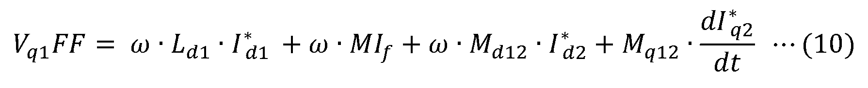
しかし、式(9)の第3項、式(10)の第4項の微分項については、電流指令(I*
d1,I*
q1)を微分することができないため、これらの項は除外し、下記式(11)、式(12)に基づいて、d軸フィードフォワード値(Vd1FF)及びq軸フィードフォワード値(Vq1FF)が演算される。


第1電流制御部12aは、下記式(13)に示すように、d軸比例積分制御部121の演算結果(Vd1FB)と、d軸非干渉制御部124の演算結果(Vd1cross)と、別途演算されたd軸フィードフォワード値(Vd1FF)とを加算して、d軸電圧指令(V*
d1)を演算する。また、第1電流制御部12aは、下記式(14)に示すように、q軸比例積分制御部122の演算結果(Vq1FB)と、q軸非干渉制御部123の演算結果(Vq1cross)と、別途演算されたq軸フィードフォワード値(Vq1FF)とを加算して、d軸電圧指令(V*
q1)を演算する。

尚、第1コイルセット81の3相の実電流(U相電流iu1ph、V相電流iv1ph、W相電流iw1ph)から、2相の実電流(Id1,Iq1)への座標変換は、3相2相第1座標変換部15aにより実行される。3相2相第1座標変換部15aは、回転センサ7(SEN-R)により検出されたロータ80rの各時点での回転位置(磁極位置、電気角θ)である第1電気角θ1(=θ)に基づいて座標変換を行う。
第1電圧制御部13aは、dq軸直交ベクトル座標系の2相電圧指令(V*
d1,V*
q1)に基づいて、第1コイルセット81に対応した3相の電圧指令を演算する。第1電圧制御部13aは、直流リンク電圧“Vdc”に基づいて2相電圧を演算する電圧演算部131と、2相電圧を3相の電圧指令に変換する2相3相座標変換部132とを備えている。
第1変調部14aは、3相の電圧指令のそれぞれに基づいて、第1インバータ51のスイッチング制御信号を生成する。ここでは、第1変調部14aが第1スイッチング周波数のキャリアに基づいて、パルス幅変調(PWM)によりスイッチング制御信号を生成する形態を例示している。本実施形態では、図1に示すように、第1インバータ51のスイッチング素子5は、SiC-MOSFETであり、Si-IGBTに比べて高いスイッチング周波数によるスイッチングが可能である。従って、第1スイッチング周波数は、第2スイッチング周波数よりも高い周波数(例えば、2~2.5倍程度)であると好適である。
続いて第2制御部10bについて説明するが、第1制御部10aと同一の箇所について適宜説明を省略する。第2電流制御部12bは、2相の電流指令(I*
d2,I*
q2)と、回転電機80の実電流(U相電流iu2ph、V相電流iv2ph、W相電流iw2ph)が座標変換された2相の実電流(Id2,Iq2)との偏差に基づいて、インバータ50に印加する電圧の指令である2相の電圧指令(V*
d2,V*
q2)を演算する。
図19に示すように、第2電流制御部12bも第1電流制御部12aと同様の機能部を備えている。d軸比例積分制御部121は、d軸電流指令(I* d2)とd軸電流(Id2)との偏差に基づいて下記式(15)に示すような演算を行い、q軸比例積分制御部122は、q軸電流指令(I* q2)とq軸電流(Iq2)との偏差に基づいて下記式(16)に示すような演算を行う。式(15)、式(16)において、“(P)Id2”及び“(P)Iq2”は比例ゲインであり、それぞれd軸q軸における自己インダクタンス(Ld2又はLq2)と、カットオフ周波数との積である。また、“(I)Id2”及び “(I)Iq2”は、第2コイルセット82の合成抵抗値“Ra”と、制御周期[秒]と、カットオフ周波数との積である。
図19に示すように、第2電流制御部12bも第1電流制御部12aと同様の機能部を備えている。d軸比例積分制御部121は、d軸電流指令(I* d2)とd軸電流(Id2)との偏差に基づいて下記式(15)に示すような演算を行い、q軸比例積分制御部122は、q軸電流指令(I* q2)とq軸電流(Iq2)との偏差に基づいて下記式(16)に示すような演算を行う。式(15)、式(16)において、“(P)Id2”及び“(P)Iq2”は比例ゲインであり、それぞれd軸q軸における自己インダクタンス(Ld2又はLq2)と、カットオフ周波数との積である。また、“(I)Id2”及び “(I)Iq2”は、第2コイルセット82の合成抵抗値“Ra”と、制御周期[秒]と、カットオフ周波数との積である。
q軸非干渉制御部123は、d軸電流指令(I*
d2)とd軸電流(Id2)との偏差に基づいて下記式(17)に示すような演算を行い、d軸非干渉制御部124は、q軸電流指令(I*
q2)とq軸電流(Iq2)との偏差に基づいて下記式(18)に示すような演算を行う。式(17)において、“(I)Idq2” は、回転速度(角速度ω)と、d軸自己インダクタンスLd2と、制御周期[秒]と、カットオフ周波数との積であり、式(18)において、“(I)Iqd2” は、回転速度(角速度ω)と、q軸自己インダクタンスLq2と、制御周期[秒]と、カットオフ周波数との積である。
また、インバータ制御装置10は、図19には不図示であるが、フィードフォワード演算部を備えており、d軸フィードフォワード値(Vd2FF)及びq軸フィードフォワード値(Vq2FF)が演算されている。理論的には、d軸フィードフォワード値(Vd2FF)及びq軸フィードフォワード値(Vq2FF)は、下記式(19)、式(20)で示される。
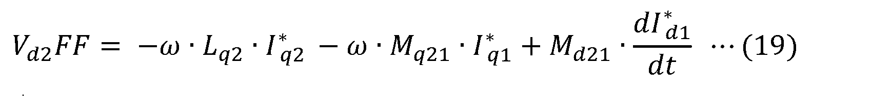

しかし、式(19)の第3項、式(20)の第4項の微分項については、電流指令(I*
d2,I*
q2)を微分することができないため、これらの項は除外し、下記式(21)、式(22)に基づいて、d軸フィードフォワード値(Vd2FF)及びq軸フィードフォワード値(Vq2FF)が演算される。
第2電流制御部12bは、下記式(23)に示すように、d軸比例積分制御部121の演算結果(Vd2FB)と、d軸非干渉制御部124の演算結果(Vd2cross)と、別途演算されたd軸フィードフォワード値(Vd2FF)とを加算して、d軸電圧指令(V*
d2)を演算する。また、第2電流制御部12bは、下記式(24)に示すように、q軸比例積分制御部122の演算結果(Vq2FB)と、q軸非干渉制御部123の演算結果(Vq2cross)と、別途演算されたq軸フィードフォワード値(Vq2FF)とを加算して、d軸電圧指令(V*
q2)を演算する。
第2コイルセット82の3相の実電流(U相電流iu2ph、V相電流iv2ph、W相電流iw2ph)から、2相の実電流(Id2,Iq2)への座標変換は、3相2相第2座標変換部15bにより実行される。3相2相第2座標変換部15bは、回転センサ7(SEN-R)により検出されたロータ80rの各時点での回転位置(磁極位置、電気角θ)に基づいて、座標変換を行う。図2を参照して上述したように、第1コイルセット81と、第2コイルセット82とには、30度(π/6)位相が異なる電流が流れるように制御される。従って、3相2相第2座標変換部15bにおける座標変換で用いられる第2電気角θ2は、3相2相第1座標変換部15aにおける座標変換で用いられる第1電気角θ1と、30度(π/6)位相が異なる。第2電気角θ2は、回転センサ7により検出された電気角θから30度(π/6)位相が遅れた“θ-π/6”である。
第2電圧制御部13bは、dq軸直交ベクトル座標系の2相電圧指令(V*
d1,V*
q1)に基づいて、第2コイルセット82に対応した3相の電圧指令を演算する。第2電圧制御部13bは、直流リンク電圧“Vdc”に基づいて2相電圧を演算する電圧演算部131と、2相電圧を3相の電圧指令に変換する2相3相座標変換部132とを備えている。
第2変調部14bは、3相の電圧指令のそれぞれに基づいて、第2インバータ52のスイッチング制御信号を生成する。ここでは、第2変調部14bが第2スイッチング周波数のキャリアに基づいて、パルス幅変調によりスイッチング制御信号を生成する形態を例示している。
本実施形態では、図1に示すように、第1インバータ51のスイッチング素子5は、SiC-MOSFETであり、Si-IGBTに比べて高いスイッチング周波数によるスイッチングが可能である。従って、上述したように、第1スイッチング周波数は、第2スイッチング周波数よりも高い周波数(例えば、2~2.5倍程度)であると好適である。また、第1インバータ51は、単独で駆動される場合があり、その際には、図11や図13を参照して上述したように、スイッチング周波数がより高いことが好ましい。
〔実施形態の概要〕
以下、上記において説明した回転電機制御システム(100)の概要について簡単に説明する。
以下、上記において説明した回転電機制御システム(100)の概要について簡単に説明する。
1つの態様として、N相(Nは自然数)の第1コイルセット(81)及びN相の第2コイルセット(82)が同一のステータコアに配置された交流の回転電機(80)を制御する回転電機制御システム(100)は、直流電源(41)及び前記第1コイルセット(81)に接続されて直流とN相の交流との間で電力を変換する第1インバータ(51)と、前記直流電源(41)及び前記第2コイルセット(82)に接続されて直流とN相の交流との間で電力を変換する第2インバータ(52)と、前記第1インバータ(51)及び前記第2インバータ(52)のそれぞれを個別に制御するスイッチング制御信号を生成して、前記第1コイルセット(81)及び前記第2コイルセット(82)にそれぞれ異なる位相の電流が流れるように前記第1インバータ(51)及び前記第2インバータ(52)を制御するインバータ制御装置(10)と、を備え、前記インバータ制御装置(10)は、前記第2インバータ(52)を停止させると共に前記第1インバータ(51)をスイッチング制御して、直流とN相の交流との間で電力を変換させる、又は、前記第1インバータ(51)及び前記第2インバータ(52)の双方をスイッチング制御して、直流と2N相の交流との間で電力を変換させるものであり、前記第1インバータ(51)を構成するスイッチング素子(5)は、オフ状態とオン状態との間での遷移時間が前記第2インバータ(52)を構成するスイッチング素子よりも短く、スイッチング損失が小さい。
2つのコイルセット(8)を備えた回転電機(80)の利点の1つは、2つのコイルセット(8)に対応して2つのインバータ(50)を備えることで、インバータ(50)の負荷を低減し、より大きい交流電流を流すことを可能として回転電機(80)のトルクを増大させることにある。しかし、要求トルクによっては、1つのインバータ(50)で対応可能な交流電流により回転電機(80)に必要なトルクを出力させることも可能である。第2インバータ(52)を停止させると共に第1インバータ(51)をスイッチング制御した場合、第2コイルセット(82)には第2インバータ(52)から電流が供給されないため、第1コイルセット(51)と第2コイルセット(52)との相互インダクタンスに起因する鉄損も抑制される。一方、例えば要求トルクが高く、2つのインバータ(50)で対応すべき交流電流が必要な場合には、2N相の交流電流を回転電機(80)に流すことができるので、N相の交流電流を回転電機(80)に流す場合に比べて出力トルクを高くすることができる。即ち、本構成によれば、必要に応じて、1つのインバータ(50)を用いる制御と、2つのインバータ(50)を用いる制御とで、制御形態を切り替えることが可能である。この場合、単独で動作する第1インバータ(51)は常に動作することになるが、第2インバータ(52)は停止する場合がある。より稼働率の高い第1インバータ(51)を構成するスイッチング素子(5)が、第2インバータ(52)を構成するスイッチング素子(5)に比べてスイッチング損失が小さい素子であると、システム全体の損失を低減させることができる。一般的に、そのようにスイッチング損失が小さいスイッチング素子(5)は高価であるから、2つのインバータ(50)の内の一方である第1インバータ(51)のみに用いることで、システム全体のコストの増加を抑制することができる。即ち、本構成によれば、2つのコイルセット(8)を備えた交流の回転電機(80)を制御対象とするシステムにおいて、システムコストの増大を抑制しつつ、システム効率を向上させることができる。
また、前記インバータ制御装置(10)は、前記第1インバータ(51)を第1スイッチング周波数でスイッチング制御し、前記第2インバータ(52)を前記第1スイッチング周波数よりも低い第2スイッチング周波数でスイッチング制御すると好適である。
一般的により高いスイッチング周波数でインバータ(50)をスイッチング制御する方が歪みの少ない交流を得ることができる。このような歪みは、鉄損や、振動、騒音の原因ともなるため、交流の歪みは少ない方が好ましい。第1インバータ(51)を構成するスイッチング素子(5)は、オフ状態とオン状態との間での遷移時間が第2インバータ(52)を構成するスイッチング素子よりも短く、スイッチング損失が小さい素子である。従って、第2インバータ(52)を構成するスイッチング素子に比べて、第1インバータ(51)を構成するスイッチング素子は、より高いスイッチング周波数でも効率的に動作することができる。従って、第1インバータ(51)を第1スイッチング周波数でスイッチング制御し、第2インバータ(52)を第1スイッチング周波数よりも低い第2スイッチング周波数でスイッチング制御することによって、システム効率を向上させることができる。
また、前記インバータ制御装置(10)は、前記回転電機(80)のトルクと回転速度によって規定される前記回転電機(80)の動作領域の内、第1領域(R1)では、前記第2インバータ(52)を停止させると共に前記第1インバータ(51)をスイッチング制御して、直流とN相の交流との間で電力を変換させ、前記第1領域(R1)よりも高トルク側の領域である第2領域(R2)では、前記第1インバータ(51)及び前記第2インバータ(52)をスイッチング制御して、直流と2N相の交流との間で電力を変換させると好適である。
一般的に、回転電機(80)の動作領域の内で最も頻度が高いのは、相対的に低トルク側の領域であることが多い。上述したように、2つのコイルセット(8)を備えた回転電機(80)の利点の1つは、2つのコイルセット(8)に対応して2つのインバータ(50)を備えることで、インバータ(50)の負荷を低減し、より大きい交流電流を流して回転電機(80)のトルクを増大させることにある。しかし、相対的に低トルク側であれば、1つのインバータ(50)で対応可能な交流電流により回転電機(80)に必要なトルクを出力させることも可能である。第2インバータ(52)を停止させると共に第1インバータ(51)をスイッチング制御した場合、第2コイルセット(82)には第2インバータ(52)から電流が供給されないため、第1コイルセット(81)と第2コイルセット(82)との相互インダクタンスに起因する鉄損も抑制される。本構成によれば、回転電機(80)の動作領域の内、相対的に低トルク側の領域である第1領域(R1)において、インバータ制御装置(10)は、第2インバータ(52)を停止させると共に第1インバータ(51)をスイッチング制御して、直流とN相の交流との間で電力を変換させる。つまり、回転電機(80)の動作領域の内、最も頻度が高いと考えられる第1領域(R1)における鉄損が低減されるので、システム効率を向上させることができる。相対的に高トルク側の第2領域(R2)では、インバータ制御装置(10)は、第1インバータ(51)及び第2インバータ(52)をスイッチング制御して、直流と2N相の交流との間で電力を変換するため、回転電機(80)に要求されるトルクを出力させることができる。この場合、相互インダクタンスに起因する鉄損は生じる。しかし、第2領域(R2)における回転電機(80)の運転頻度は第1領域(R1)における回転電機(80)の運転頻度に比べて低いため、システム効率を低下させる影響は、第1領域(R1)に比べて小さい。
ここで、前記インバータ制御装置(10)は、前記第1コイルセット(81)と前記第2コイルセット(82)とに、(π/2N)位相が異なる電流が流れるように、前記第1インバータ(51)及び前記第2インバータ(52)を制御すると好適である。
この構成によれば、インバータ制御装置(10)は、第1インバータ(51)及記第2インバータ(52)を個別にスイッチング制御して、適切に直流と2N相の交流との間で電力を変換させることができる。
また、前記第1領域(R1)及び前記第2領域(R2)は、前記回転電機(80)のトルクと回転速度とに基づいて設定されている、或いは、前記第1インバータ(51)及び前記第2インバータ(52)の直流側の電圧と前記回転電機(80)の逆起電圧とに基づいて設定されている、と好適である。
回転電機(80)の動作領域は、トルクと回転速度との関係や、インバータ(50)の直流側の電圧と逆起電圧との関係等で規定することができる。そして、そのような動作領域の中で、相対的に使用頻度の高い動作領域と、使用頻度の低い動作領域とを特定することができる。従って、第1領域(R1)及び第2領域(R2)が上記のように設定されていると、適切に第1インバータ(51)及び第2インバータ(52)の双方を用いて電力を変換する制御モードと、第2インバータ(52)を停止させて第1インバータ(51)のみで電力を変換する制御モードとを選択することができる。
また、前記インバータ制御装置(10)は、前記回転電機(80)の動作領域が前記第1領域(R1)から前記第2領域(R2)へ移行する場合に、前記回転電機(80)の出力トルクを維持した状態で、前記第1コイルセット(81)に流す電流を低下させ、当該低下する電流に相当する電流を前記第2コイルセット(82)に流すように、前記第1インバータ(51)及び前記第2インバータ(52)をスイッチング制御すると好適である。
2つのコイルセット(8)に通電して回転電機(80)を制御する場合と、1つのみのコイルセット(8)に通電して回転電機(80)を制御する場合とでは、当然ながら、最適な動作条件が異なる。そのため、1つのみのコイルセット(8)に通電する状態から、2つのコイルセット(8)に通電する状態へと制御形態を切り替える際、例え出力トルクが同じであったとしても、それぞれのインバータ(50)の動作条件を変更する必要があり、制御形態を急激に切り替えると、トルク変動を生じる可能性がある。本構成によれば、2つのコイルセット(8)に流れる電流の差が縮まるように制御することによって、円滑に制御形態を切り替えることができる。
また、前記インバータ制御装置(10)は、前記第2領域(R2)では、前記第1コイルセット(81)及び前記第2コイルセット(82)に実効値が同じ電流が流れるように、前記第1インバータ(51)及び前記第2インバータ(52)をスイッチング制御すると好適である。
この構成によれば、安定した2N相の交流を得ることができるので、適切に回転電機(80)を駆動することができる。
) また、前記インバータ制御装置(10)は、前記回転電機(80)の目標トルク(T*)に基づいて設定される前記第1コイルセット(81)の電流指令である第1電流指令(I*
d1,I*
q1)と前記第1コイルセット(81)に流れる電流(Id1,Iq1)との偏差に基づいて前記第1インバータ(51)をスイッチング制御すると共に、前記回転電機(80)の目標トルク(T*)に基づいて設定される前記第2コイルセット(82)の電流指令である第2電流指令(I*
d2,I*
q2)と前記第2コイルセット(82)に流れる電流(Id2,Iq2)との偏差に基づいて前記第2インバータ(52)をスイッチング制御して、前記回転電機(80)を電流フィードバック制御するものであり、前記第1領域(R1)におけるフィードバックゲインが、前記第2領域(R2)におけるフィードバックゲインよりも高い値に設定されていると好適である。
2つのインバータ(50)を介して2つのコイルセット(8)に通電されている場合には、2つのコイルセット(8)の間の相互インダクタンスの影響により外乱が発生し易く、フィードバックゲインが高くなるに従って、制御が収束しにくく易くなる。一方、1つのインバータ(50)を介して1つのコイルセット(8)にのみ通電されている場合には、相互インダクタンスの影響による外乱は少なく、2つのコイルセット(8)が通電されている場合に比べてフィードバックゲインを高くし易い。そして、フィードバックゲインが高くなるに従って、収束時間は短くなる。従って、回転電機(80)の動作領域の内での頻度が高い第1領域(R1)におけるフィードバック制御では、第2領域(R2)におけるフィードバック制御の際のフィードバックゲインよりも高い値のフィードバックゲインを用いるとシステム効率を向上させることができる。
5 :スイッチング素子
10 :インバータ制御装置
41 :直流電源
51 :第1インバータ
52 :第2インバータ
80 :回転電機
81 :第1コイルセット
82 :第2コイルセット
100 :回転電機制御システム
I* d1,I* q1:第1電流指令
I* d2,I* q2:第2電流指令
Id1,Iq1 :第1コイルセットに流れる電流
Id2,Iq2 :第2コイルセットに流れる電流
R1 :第1領域
R2 :第2領域
T* :目標トルク
10 :インバータ制御装置
41 :直流電源
51 :第1インバータ
52 :第2インバータ
80 :回転電機
81 :第1コイルセット
82 :第2コイルセット
100 :回転電機制御システム
I* d1,I* q1:第1電流指令
I* d2,I* q2:第2電流指令
Id1,Iq1 :第1コイルセットに流れる電流
Id2,Iq2 :第2コイルセットに流れる電流
R1 :第1領域
R2 :第2領域
T* :目標トルク
Claims (8)
- N相(Nは自然数)の第1コイルセット及びN相の第2コイルセットが同一のステータコアに配置された交流の回転電機を制御する回転電機制御システムであって、
直流電源及び前記第1コイルセットに接続されて直流とN相の交流との間で電力を変換する第1インバータと、
前記直流電源及び前記第2コイルセットに接続されて直流とN相の交流との間で電力を変換する第2インバータと、
前記第1インバータ及び前記第2インバータのそれぞれを個別に制御するスイッチング制御信号を生成して、前記第1コイルセット及び前記第2コイルセットにそれぞれ異なる位相の電流が流れるように前記第1インバータ及び前記第2インバータを制御するインバータ制御装置と、を備え、
前記インバータ制御装置は、
前記第2インバータを停止させると共に前記第1インバータをスイッチング制御して、直流とN相の交流との間で電力を変換させる、又は、
前記第1インバータ及び前記第2インバータの双方をスイッチング制御して、直流と2N相の交流との間で電力を変換させるものであり、
前記第1インバータを構成するスイッチング素子は、オフ状態とオン状態との間での遷移時間が前記第2インバータを構成するスイッチング素子よりも短く、スイッチング損失が小さい、回転電機制御システム。 - 前記インバータ制御装置は、前記第1インバータを第1スイッチング周波数でスイッチング制御し、前記第2インバータを前記第1スイッチング周波数よりも低い第2スイッチング周波数でスイッチング制御する、請求項1に記載の回転電機制御システム。
- 前記インバータ制御装置は、
前記回転電機のトルクと回転速度によって規定される前記回転電機の動作領域の内、第1領域では、前記第2インバータを停止させると共に前記第1インバータをスイッチング制御して、直流とN相の交流との間で電力を変換させ、
前記第1領域よりも高トルク側の領域である第2領域では、前記第1インバータ及び前記第2インバータをスイッチング制御して、直流と2N相の交流との間で電力を変換させる、請求項1又は2に記載の回転電機制御システム。 - 前記インバータ制御装置は、前記第1コイルセットと前記第2コイルセットとに、(π/2N)位相が異なる電流が流れるように、前記第1インバータ及び前記第2インバータを制御する、請求項3に記載の回転電機制御システム。
- 前記第1領域及び前記第2領域は、前記回転電機のトルクと回転速度とに基づいて設定されている、或いは、前記第1インバータ及び前記第2インバータの直流側の電圧と前記回転電機の逆起電圧とに基づいて設定されている、請求項3又は4に記載の回転電機制御システム。
- 前記インバータ制御装置は、前記回転電機の動作領域が前記第1領域から前記第2領域へ移行する場合に、前記回転電機の出力トルクを維持した状態で、前記第1コイルセットに流す電流を低下させ、当該低下する電流に相当する電流を前記第2コイルセットに流すように、前記第1インバータ及び前記第2インバータをスイッチング制御する、請求項3から5の何れか一項に記載の回転電機制御システム。
- 前記インバータ制御装置は、前記第2領域では、前記第1コイルセット及び前記第2コイルセットに実効値が同じ電流が流れるように、前記第1インバータ及び前記第2インバータをスイッチング制御する、請求項3から6の何れか一項に記載の回転電機制御システム。
- 前記インバータ制御装置は、前記回転電機の目標トルクに基づいて設定される前記第1コイルセットの電流指令である第1電流指令と前記第1コイルセットに流れる電流との偏差に基づいて前記第1インバータをスイッチング制御すると共に、前記回転電機の目標トルクに基づいて設定される前記第2コイルセットの電流指令である第2電流指令と前記第2コイルセットに流れる電流との偏差に基づいて前記第2インバータをスイッチング制御して、前記回転電機を電流フィードバック制御するものであり、
前記第1領域におけるフィードバックゲインが、前記第2領域におけるフィードバックゲインよりも高い値に設定されている、請求項3から7の何れか一項に記載の回転電機制御システム。
Priority Applications (4)
| Application Number | Priority Date | Filing Date | Title |
|---|---|---|---|
| EP20826943.1A EP3989435A4 (en) | 2019-06-21 | 2020-06-17 | SYSTEM FOR CONTROLLING AN ELECTRIC ROTARY MACHINE |
| CN202080039329.2A CN113892230B (zh) | 2019-06-21 | 2020-06-17 | 旋转电机控制系统 |
| JP2021526820A JP7238982B2 (ja) | 2019-06-21 | 2020-06-17 | 回転電機制御システム |
| US17/598,983 US11705850B2 (en) | 2019-06-21 | 2020-06-17 | Rotating electrical machine control system |
Applications Claiming Priority (4)
| Application Number | Priority Date | Filing Date | Title |
|---|---|---|---|
| JP2019-115706 | 2019-06-21 | ||
| JP2019-115705 | 2019-06-21 | ||
| JP2019115706 | 2019-06-21 | ||
| JP2019115705 | 2019-06-21 |
Publications (1)
| Publication Number | Publication Date |
|---|---|
| WO2020255988A1 true WO2020255988A1 (ja) | 2020-12-24 |
Family
ID=74036951
Family Applications (1)
| Application Number | Title | Priority Date | Filing Date |
|---|---|---|---|
| PCT/JP2020/023682 Ceased WO2020255988A1 (ja) | 2019-06-21 | 2020-06-17 | 回転電機制御システム |
Country Status (5)
| Country | Link |
|---|---|
| US (1) | US11705850B2 (ja) |
| EP (1) | EP3989435A4 (ja) |
| JP (1) | JP7238982B2 (ja) |
| CN (1) | CN113892230B (ja) |
| WO (1) | WO2020255988A1 (ja) |
Cited By (5)
| Publication number | Priority date | Publication date | Assignee | Title |
|---|---|---|---|---|
| CN113612428A (zh) * | 2021-10-09 | 2021-11-05 | 天津飞旋科技股份有限公司 | 应用于飞轮储能的电机驱动器及控制方法 |
| US20220077807A1 (en) * | 2020-09-04 | 2022-03-10 | Hyundai Motor Company | Motor driving device and method |
| US20230115925A1 (en) * | 2021-10-08 | 2023-04-13 | Hyundai Motor Company | Motor driving apparatus |
| US11909343B2 (en) | 2020-03-30 | 2024-02-20 | Hyundai Motor Company | Motor-driving apparatus |
| US12034391B2 (en) | 2020-03-30 | 2024-07-09 | Hyundai Motor Company | Motor-driving apparatus |
Families Citing this family (6)
| Publication number | Priority date | Publication date | Assignee | Title |
|---|---|---|---|---|
| CN111030550B (zh) * | 2019-11-25 | 2022-05-17 | 华为技术有限公司 | 一种电机驱动器及动力系统 |
| CN114731114B (zh) * | 2019-11-27 | 2025-07-25 | 三菱电机株式会社 | 电动机控制装置 |
| WO2021144234A1 (de) * | 2020-01-13 | 2021-07-22 | Convertertec Deutschland Gmbh | Verfahren zum phasengetrennten überstromschutz einer dreiphasigen brückenschaltung |
| JP7230886B2 (ja) * | 2020-06-17 | 2023-03-01 | 株式会社デンソー | モータ制御装置、及び操舵システム |
| US11533013B1 (en) * | 2021-07-29 | 2022-12-20 | Rivian Ip Holdings, Llc | Pulse width modulation clock synchronization |
| CN116826750B (zh) * | 2023-06-30 | 2025-08-26 | 温州大学 | 一种混合并联一体化电源的控制方法 |
Citations (11)
| Publication number | Priority date | Publication date | Assignee | Title |
|---|---|---|---|---|
| JP2008193870A (ja) * | 2007-02-07 | 2008-08-21 | Toshiba Carrier Corp | 圧縮機駆動装置および冷凍サイクル装置 |
| JP2009023790A (ja) * | 2007-07-19 | 2009-02-05 | Mitsubishi Electric Corp | エレベータの制御装置 |
| JP2010098808A (ja) * | 2008-10-15 | 2010-04-30 | Jtekt Corp | モータ制御装置 |
| JP2010226899A (ja) * | 2009-03-25 | 2010-10-07 | Nippon Muugu Kk | 電動機システム |
| JP2011024377A (ja) * | 2009-07-17 | 2011-02-03 | Toshiba Carrier Corp | 圧縮機駆動装置および冷凍サイクル装置 |
| JP2011078230A (ja) * | 2009-09-30 | 2011-04-14 | Denso Corp | 多相回転機の制御装置、および、これを用いた電動パワーステアリング装置 |
| JP2012143100A (ja) * | 2011-01-05 | 2012-07-26 | Mitsutoyo Corp | 制御装置、および測定装置 |
| JP2017147840A (ja) * | 2016-02-17 | 2017-08-24 | 株式会社デンソー | 3相回転機の制御装置、及び、電動パワーステアリング装置 |
| WO2017216959A1 (ja) * | 2016-06-17 | 2017-12-21 | 三菱電機株式会社 | モータシステム、モータ駆動装置、冷凍サイクル装置および空気調和機 |
| WO2018025331A1 (ja) * | 2016-08-02 | 2018-02-08 | 三菱電機株式会社 | モータ駆動装置、冷蔵庫及び空気調和機 |
| JP2018130007A (ja) | 2016-11-11 | 2018-08-16 | 株式会社デンソー | 回転電機制御装置、および、これを用いた電動パワーステアリング装置 |
Family Cites Families (11)
| Publication number | Priority date | Publication date | Assignee | Title |
|---|---|---|---|---|
| JP5645083B2 (ja) * | 2011-06-28 | 2014-12-24 | アイシン・エィ・ダブリュ株式会社 | 回転電機制御装置 |
| JP5449429B2 (ja) * | 2012-02-24 | 2014-03-19 | 三菱電機株式会社 | 交流回転機の制御装置及びその方法、電動パワーステアリング装置 |
| JP5556845B2 (ja) * | 2012-04-26 | 2014-07-23 | 株式会社デンソー | 3相回転機の制御装置 |
| JP6295782B2 (ja) * | 2014-03-31 | 2018-03-20 | 株式会社安川電機 | 電力変換装置、発電システム、制御装置および電力変換方法 |
| JP6360442B2 (ja) * | 2015-01-14 | 2018-07-18 | 株式会社日立製作所 | 永久磁石同期モータ、巻線切替モータ駆動装置、及び、それらを用いた冷凍空調機器、電動車両 |
| JP6342060B2 (ja) * | 2015-02-24 | 2018-06-13 | 三菱電機株式会社 | 電動駆動装置、及び電動パワーステアリング装置 |
| US10644642B2 (en) * | 2016-03-14 | 2020-05-05 | Mitsubishi Electric Corporation | Three phase duplexing motor for electric power steering apparatus |
| WO2018037457A1 (ja) | 2016-08-22 | 2018-03-01 | 三菱電機株式会社 | モータ駆動装置、冷凍サイクル装置及び空気調和機 |
| EP3293878B1 (en) | 2016-09-09 | 2021-06-23 | Black & Decker Inc. | Dual-inverter for a brushless motor |
| JP6769247B2 (ja) * | 2016-11-04 | 2020-10-14 | 株式会社デンソー | 回転電機システム |
| JP7095550B2 (ja) * | 2018-10-18 | 2022-07-05 | 株式会社デンソー | 回転電機の制御装置及び回転電機の制御方法 |
-
2020
- 2020-06-17 WO PCT/JP2020/023682 patent/WO2020255988A1/ja not_active Ceased
- 2020-06-17 CN CN202080039329.2A patent/CN113892230B/zh active Active
- 2020-06-17 US US17/598,983 patent/US11705850B2/en active Active
- 2020-06-17 EP EP20826943.1A patent/EP3989435A4/en active Pending
- 2020-06-17 JP JP2021526820A patent/JP7238982B2/ja active Active
Patent Citations (11)
| Publication number | Priority date | Publication date | Assignee | Title |
|---|---|---|---|---|
| JP2008193870A (ja) * | 2007-02-07 | 2008-08-21 | Toshiba Carrier Corp | 圧縮機駆動装置および冷凍サイクル装置 |
| JP2009023790A (ja) * | 2007-07-19 | 2009-02-05 | Mitsubishi Electric Corp | エレベータの制御装置 |
| JP2010098808A (ja) * | 2008-10-15 | 2010-04-30 | Jtekt Corp | モータ制御装置 |
| JP2010226899A (ja) * | 2009-03-25 | 2010-10-07 | Nippon Muugu Kk | 電動機システム |
| JP2011024377A (ja) * | 2009-07-17 | 2011-02-03 | Toshiba Carrier Corp | 圧縮機駆動装置および冷凍サイクル装置 |
| JP2011078230A (ja) * | 2009-09-30 | 2011-04-14 | Denso Corp | 多相回転機の制御装置、および、これを用いた電動パワーステアリング装置 |
| JP2012143100A (ja) * | 2011-01-05 | 2012-07-26 | Mitsutoyo Corp | 制御装置、および測定装置 |
| JP2017147840A (ja) * | 2016-02-17 | 2017-08-24 | 株式会社デンソー | 3相回転機の制御装置、及び、電動パワーステアリング装置 |
| WO2017216959A1 (ja) * | 2016-06-17 | 2017-12-21 | 三菱電機株式会社 | モータシステム、モータ駆動装置、冷凍サイクル装置および空気調和機 |
| WO2018025331A1 (ja) * | 2016-08-02 | 2018-02-08 | 三菱電機株式会社 | モータ駆動装置、冷蔵庫及び空気調和機 |
| JP2018130007A (ja) | 2016-11-11 | 2018-08-16 | 株式会社デンソー | 回転電機制御装置、および、これを用いた電動パワーステアリング装置 |
Non-Patent Citations (1)
| Title |
|---|
| See also references of EP3989435A4 |
Cited By (8)
| Publication number | Priority date | Publication date | Assignee | Title |
|---|---|---|---|---|
| US11909343B2 (en) | 2020-03-30 | 2024-02-20 | Hyundai Motor Company | Motor-driving apparatus |
| US12034391B2 (en) | 2020-03-30 | 2024-07-09 | Hyundai Motor Company | Motor-driving apparatus |
| US12341458B2 (en) | 2020-03-30 | 2025-06-24 | Hyundai Motor Company | Motor-driving apparatus |
| US12456941B2 (en) | 2020-03-30 | 2025-10-28 | Hyundai Motor Company | Motor-driving apparatus |
| US20220077807A1 (en) * | 2020-09-04 | 2022-03-10 | Hyundai Motor Company | Motor driving device and method |
| US20230115925A1 (en) * | 2021-10-08 | 2023-04-13 | Hyundai Motor Company | Motor driving apparatus |
| US12176768B2 (en) * | 2021-10-08 | 2024-12-24 | Hyundai Motor Company | Motor driving apparatus |
| CN113612428A (zh) * | 2021-10-09 | 2021-11-05 | 天津飞旋科技股份有限公司 | 应用于飞轮储能的电机驱动器及控制方法 |
Also Published As
| Publication number | Publication date |
|---|---|
| JPWO2020255988A1 (ja) | 2020-12-24 |
| EP3989435A4 (en) | 2022-09-14 |
| JP7238982B2 (ja) | 2023-03-14 |
| CN113892230A (zh) | 2022-01-04 |
| CN113892230B (zh) | 2026-01-02 |
| US20220200508A1 (en) | 2022-06-23 |
| US11705850B2 (en) | 2023-07-18 |
| EP3989435A1 (en) | 2022-04-27 |
Similar Documents
| Publication | Publication Date | Title |
|---|---|---|
| JP7238982B2 (ja) | 回転電機制御システム | |
| CN106105013B (zh) | 旋转电机控制装置 | |
| CN102474208B (zh) | 电动机驱动装置的控制装置 | |
| JP6394030B2 (ja) | インバータ制御装置 | |
| Khanh et al. | Advanced PMSM speed control using fuzzy PI method for hybrid power control technique | |
| JP5370769B2 (ja) | 電動機駆動装置の制御装置 | |
| CN110063012A (zh) | 逆变器控制装置 | |
| JP5485232B2 (ja) | スイッチング回路の制御装置 | |
| JP5803559B2 (ja) | 回転電機制御装置 | |
| US9935568B2 (en) | Control apparatus of rotary electric machine | |
| WO2011040169A1 (ja) | 制御装置 | |
| WO2021145029A1 (ja) | 回転電機制御装置 | |
| EP4210215B1 (en) | Rotary electrical machine control system | |
| CN113381649B (zh) | 用于直流无刷电机的控制方法和控制装置 | |
| JP7609705B2 (ja) | 電力変換装置 | |
| JP7092257B2 (ja) | 回転電機制御システム | |
| JP7393763B2 (ja) | 回転電機制御システム | |
| JP7211242B2 (ja) | 変調方式切替装置 | |
| JP2014050123A (ja) | ロータ位置推定装置、電動機制御システムおよびロータ位置推定方法 | |
| JP7446185B2 (ja) | 回転電機制御システム | |
| JP2003018887A (ja) | 電動機制御装置及び方法 | |
| JP2013021869A (ja) | スイッチング回路の制御装置 | |
| JP4526628B2 (ja) | 交流モータの制御装置 | |
| JP7571648B2 (ja) | 回転電機制御システム | |
| JP7423480B2 (ja) | 回転電機制御システム |
Legal Events
| Date | Code | Title | Description |
|---|---|---|---|
| 121 | Ep: the epo has been informed by wipo that ep was designated in this application |
Ref document number: 20826943 Country of ref document: EP Kind code of ref document: A1 |
|
| ENP | Entry into the national phase |
Ref document number: 2021526820 Country of ref document: JP Kind code of ref document: A |
|
| NENP | Non-entry into the national phase |
Ref country code: DE |
|
| WWE | Wipo information: entry into national phase |
Ref document number: 2020826943 Country of ref document: EP |