WO2020256061A1 - 送受信方法および送受信システム - Google Patents
送受信方法および送受信システム Download PDFInfo
- Publication number
- WO2020256061A1 WO2020256061A1 PCT/JP2020/023937 JP2020023937W WO2020256061A1 WO 2020256061 A1 WO2020256061 A1 WO 2020256061A1 JP 2020023937 W JP2020023937 W JP 2020023937W WO 2020256061 A1 WO2020256061 A1 WO 2020256061A1
- Authority
- WO
- WIPO (PCT)
- Prior art keywords
- data
- transmission
- pseudo
- receiving
- propagation path
- Prior art date
- Legal status (The legal status is an assumption and is not a legal conclusion. Google has not performed a legal analysis and makes no representation as to the accuracy of the status listed.)
- Ceased
Links
Images








Classifications
-
- H—ELECTRICITY
- H04—ELECTRIC COMMUNICATION TECHNIQUE
- H04B—TRANSMISSION
- H04B7/00—Radio transmission systems, i.e. using radiation field
- H04B7/02—Diversity systems; Multi-antenna system, i.e. transmission or reception using multiple antennas
- H04B7/04—Diversity systems; Multi-antenna system, i.e. transmission or reception using multiple antennas using two or more spaced independent antennas
- H04B7/0413—MIMO systems
-
- H—ELECTRICITY
- H04—ELECTRIC COMMUNICATION TECHNIQUE
- H04B—TRANSMISSION
- H04B17/00—Monitoring; Testing
- H04B17/0082—Monitoring; Testing using service channels; using auxiliary channels
- H04B17/0087—Monitoring; Testing using service channels; using auxiliary channels using auxiliary channels or channel simulators
-
- H—ELECTRICITY
- H04—ELECTRIC COMMUNICATION TECHNIQUE
- H04B—TRANSMISSION
- H04B17/00—Monitoring; Testing
- H04B17/30—Monitoring; Testing of propagation channels
- H04B17/391—Modelling the propagation channel
- H04B17/3912—Simulation models, e.g. distribution of spectral power density or received signal strength indicator [RSSI] for a given geographic region
-
- H—ELECTRICITY
- H04—ELECTRIC COMMUNICATION TECHNIQUE
- H04B—TRANSMISSION
- H04B7/00—Radio transmission systems, i.e. using radiation field
- H04B7/02—Diversity systems; Multi-antenna system, i.e. transmission or reception using multiple antennas
- H04B7/04—Diversity systems; Multi-antenna system, i.e. transmission or reception using multiple antennas using two or more spaced independent antennas
- H04B7/0404—Diversity systems; Multi-antenna system, i.e. transmission or reception using multiple antennas using two or more spaced independent antennas the mobile station comprising multiple antennas, e.g. to provide uplink diversity
-
- H—ELECTRICITY
- H04—ELECTRIC COMMUNICATION TECHNIQUE
- H04B—TRANSMISSION
- H04B7/00—Radio transmission systems, i.e. using radiation field
- H04B7/02—Diversity systems; Multi-antenna system, i.e. transmission or reception using multiple antennas
- H04B7/04—Diversity systems; Multi-antenna system, i.e. transmission or reception using multiple antennas using two or more spaced independent antennas
- H04B7/06—Diversity systems; Multi-antenna system, i.e. transmission or reception using multiple antennas using two or more spaced independent antennas at the transmitting station
- H04B7/0613—Diversity systems; Multi-antenna system, i.e. transmission or reception using multiple antennas using two or more spaced independent antennas at the transmitting station using simultaneous transmission
- H04B7/0615—Diversity systems; Multi-antenna system, i.e. transmission or reception using multiple antennas using two or more spaced independent antennas at the transmitting station using simultaneous transmission of weighted versions of same signal
- H04B7/0617—Diversity systems; Multi-antenna system, i.e. transmission or reception using multiple antennas using two or more spaced independent antennas at the transmitting station using simultaneous transmission of weighted versions of same signal for beam forming
-
- H—ELECTRICITY
- H04—ELECTRIC COMMUNICATION TECHNIQUE
- H04B—TRANSMISSION
- H04B7/00—Radio transmission systems, i.e. using radiation field
- H04B7/02—Diversity systems; Multi-antenna system, i.e. transmission or reception using multiple antennas
- H04B7/04—Diversity systems; Multi-antenna system, i.e. transmission or reception using multiple antennas using two or more spaced independent antennas
- H04B7/08—Diversity systems; Multi-antenna system, i.e. transmission or reception using multiple antennas using two or more spaced independent antennas at the receiving station
- H04B7/0837—Diversity systems; Multi-antenna system, i.e. transmission or reception using multiple antennas using two or more spaced independent antennas at the receiving station using pre-detection combining
- H04B7/0842—Weighted combining
- H04B7/086—Weighted combining using weights depending on external parameters, e.g. direction of arrival [DOA], predetermined weights or beamforming
-
- H—ELECTRICITY
- H04—ELECTRIC COMMUNICATION TECHNIQUE
- H04W—WIRELESS COMMUNICATION NETWORKS
- H04W16/00—Network planning, e.g. coverage or traffic planning tools; Network deployment, e.g. resource partitioning or cells structures
- H04W16/24—Cell structures
- H04W16/28—Cell structures using beam steering
-
- H—ELECTRICITY
- H04—ELECTRIC COMMUNICATION TECHNIQUE
- H04W—WIRELESS COMMUNICATION NETWORKS
- H04W28/00—Network traffic management; Network resource management
- H04W28/16—Central resource management; Negotiation of resources or communication parameters, e.g. negotiating bandwidth or QoS [Quality of Service]
- H04W28/18—Negotiating wireless communication parameters
Definitions
- the present invention relates to communication technology using electromagnetic waves such as mobile communication, wireless communication, and optical communication, and relates to technologies such as data transmission / reception and multiplexing methods using resources such as frequency.
- OFDMA time division multiple access
- FDMA frequency division multiple access
- OFDMA orthogonal frequency division multiple access
- OFDMA is a user-specific frequency-selective fading in which a plurality of subscribers are provided with a frequency-time division block, that is, a resource block, for a subcarrier group generated by an OFDM method (OFDM: orthogonal wave frequency division multiplexing modulation). It is a method that allocates corresponding to the above and enables simultaneous access to multiple users.
- MIMO Multiple Input Multiple Output
- Beamforming is a technique for enhancing the directivity of electromagnetic waves in a predetermined direction, and corresponding antenna techniques include a phased array antenna and the like.
- Conventional beamforming has been a parabolic antenna or a multi-antenna by hardware, but in recent years, it has become possible to perform amplitude control and phase control for each antenna element by software using MIMO.
- Non-Patent Documents 1 and 2 describe the basic technology of a MIMO system for 4th generation mobile communication.
- Non-Patent Document 3 describes a multi-antenna wireless transmission technique.
- Non-Patent Document 4 describes a basic technique of a beamforming method.
- An object of the present invention is to provide a technique capable of improving utilization efficiency of resources such as frequency with respect to MIMO, beamforming and the like.
- a typical embodiment of the present invention has the following configuration.
- the transmission / reception method of one embodiment is a transmission / reception method for transmitting / receiving data between a transmission device having a plurality of transmission antennas and a reception device having a reception antenna, and the transmission device or the reception device is the plurality. Based on the characteristics of the plurality of actual propagation paths between the transmitting antenna and the receiving antenna of the above, a plurality of pseudo-propagation paths having characteristics similar to the characteristics of the plurality of actual propagation paths to the extent that the frequency characteristics can be approximated.
- the generation step of generating the characteristics and the transmission device create one or more transmission data by reflecting the characteristics of the plurality of pseudo-propagation paths on a plurality of parallel and independent data, and radio waves from the plurality of transmission antennas. And a reception step in which the receiving device extracts the plurality of data from one or more received data received as radio waves by the receiving antenna based on the characteristics of the plurality of pseudo propagation paths.
- the transmitting device has a MIMO transmitting function
- the receiving device has a plurality of receiving antennas as the receiving antenna, has a MIMO receiving function
- the generation step is the transmitting device or the said.
- the receiving device In a step in which the receiving device generates the characteristics of the plurality of pseudo-propagation paths based on the characteristics of the plurality of actual propagation paths including the diagonal propagation paths between the plurality of transmitting antennas and the plurality of receiving antennas.
- the diagonal propagation path is a propagation path other than the propagation path that faces one-to-one between the plurality of transmitting antennas and the plurality of receiving antennas, and the transmitting step is performed by the transmitting device.
- This is a step of creating a plurality of parallel and independent transmission data by reflecting the characteristics of the plurality of pseudo propagation paths on a plurality of data and transmitting the plurality of transmission antennas as radio waves by using the MIMO transmission function.
- the receiving device creates a plurality of received data from the signals received as radio waves by the plurality of receiving antennas by using the MIMO reception function, and the characteristics of the plurality of pseudo propagation paths are created from the plurality of received data. Is a step of extracting the plurality of data based on the above.
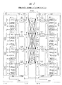
- FIG. 5 is a diagram showing a method of reducing the cross-correlation of diagonal propagation paths in MIMO in the first embodiment. It is a figure which shows the ability comparison of the cross-correlation about the extension using the pseudo-transmission characteristic in Embodiment 1.
- FIG. 5 is a diagram showing a method of reducing the cross-correlation of diagonal propagation paths in MIMO in the first embodiment. It is a figure which shows the ability comparison of the cross-correlation about the extension using the pseudo-transmission characteristic in Embodiment 1.
- FIG. 1 shows the configuration example of the MIMO system as the transmission / reception method and system of Embodiment 2 of this invention. It is a figure which shows the simulation example of the frequency selective fading in Embodiment 2. It is a figure which shows the removal effect of frequency selective fading in Embodiment 2. It is a figure which shows the signal conversion for the frequency selective fading reduction in Embodiment 2. It is a figure which shows the configuration example of the beamforming system as the transmission / reception method and system of Embodiment 3 of this invention. It is a figure which shows the use example in Embodiment 3. FIG. It is a figure which shows 1 of the method of generating a plurality of pseudo-delay profile models in Embodiment 3. FIG.
- FIG. It is a figure which shows the 2 of the method 2 of the generation method of a plurality of pseudo delay profile models in Embodiment 3.
- FIG. It is a figure which shows 3 of the method of generating a plurality of pseudo delay profile models in Embodiment 3.
- FIG. It is a figure which shows the structure of the frame of OFDM and CP in Embodiment 3.
- FIG. It is a figure which shows the structure of the modification which concerns on Embodiments 3 and 4.
- FIG. 1 shows the configuration example of the FIR filter of the pseudo propagation path. It is a figure which shows the transmission / reception method and the structure of the system in MIMO of the prior art example. It is a figure which shows the transmission / reception method and the structure of the system in the beamforming of the prior art example. It is a figure which shows the detailed structure example in MIMO of the prior art example.
- MIMO technology which was born in the latter half of the 3rd generation, can be mentioned as the main technology that supports the speeding up of 5th generation mobile communication.
- FIG. 21 shows the configuration of the basic functions of MIMO communication.
- FIG. 21 shows an example of 4 ⁇ 4 MIMO.
- the system of FIG. 21 has a transmitting station X1 such as a radio base station and a receiving station X2 such as a user terminal, and transmits / receives data from the transmitting station X1 to the receiving station X2 by MIMO.
- the four input data are transmitted to the receiving station X2 as four radio waves X4 from the four antenna elements of the antenna X3, which is a 4 ⁇ 4 MIMO communication antenna, after MIMO modulation.
- the four radio waves X4 have the characteristics h11, h22, h33, and h44 as the characteristics X5 of each of the four propagation paths.
- the four radio waves X4 travel through the propagation path of each characteristic X5 and reach the receiving station X2 which is a user terminal which is a subscriber.
- the receiving station X2 receives MIMO from the four radio waves X4 through the antenna X6, which is a 4 ⁇ 4 MIMO communication antenna.
- the receiving station X2 analyzes and extracts these four data from the received signal. These data, including some noise components, are equal to the four input data sent by the transmitter. In this way, the 4x4 MIMO system can transmit four pieces of data on the same frequency band. That is, the 4 ⁇ 4 MIMO system can achieve a transmission speed four times faster than the SISO system having one transmitting / receiving antenna.
- the diagonal transmission line is a propagation path other than the one-to-one facing propagation path corresponding to each data. For example, if the propagation path from the antenna A1 to the antenna B1 is the opposite propagation path, the propagation path from the antenna A1 to the antenna B2 or the like is a diagonal propagation path.
- the MIMO system is also used, but a new function has been added to its usage, which is called beamforming.
- FIG. 22 shows an outline of a MIMO system used for beamforming, in other words, a beamforming system.
- the example of FIG. 22 shows an outline of communication by the beamforming function in a 4 ⁇ N MIMO system.
- FIG. 22 there are a plurality of subscribers, and the subscribers YU1 to YU4 are shown.
- Receiving stations which are user terminals owned by each subscriber, are indicated by receiving stations Y21 to Y24. It has data D1 to D4 as transmission data on the transmission station Y1 side.
- data D1 is transmitted to subscriber YU1
- data D2 is transmitted to subscriber YU2
- data D3 is transmitted to subscriber YU3
- data D4 is transmitted to subscriber YU4.
- the signal of the data D1 is fed to all of the plurality of antennas A1 to A4 of the antenna Y3 which is the MIMO antenna, and at that time, the amplitude and phase delay are applied to each antenna and fed.
- the feeding signals of the destinations for each subscriber to which the amplitude and the phase delay are applied are indicated by the feeding signals Y41, Y42, Y43, and Y44.
- Radio waves Y51, Y52, Y53, and Y54 that are transmitted from each antenna and reach the receiving station of each subscriber based on this power feeding signal are shown.
- the radio wave group Y50 includes these radio waves.
- the radio wave for each subscriber becomes a beam directed to a different position for each receiving station of the subscriber.
- the beam to each receiving station is considered so that the received power at the other receiving stations is low.
- each receiving station can receive the radio waves transmitted to each of them with high quality while sharing the same frequency band.
- Each receiving station decodes the transmission signal carried by the radio wave and extracts the data which is the reception signal.
- the extracted data is indicated by data D1c, D2c, D3c, and D4c. In this way, the terminals of the four subscribers can receive the data sent individually.
- the beamforming system of FIG. 22 can transmit data to four subscribers, but for each subscriber. Since the amplitude and phase of the radio waves emitted from the four transmitting antennas are controlled to form one radio wave beam, it is inevitable that the data supplied to the four transmitting antennas is the same, and per subscriber. As a result, only 1x the data can be received. For this reason, in the 5th generation mobile communication, a means for increasing the number of modulation multi-values is adopted as a means for increasing the communication speed while using only one beam in the beamforming function. This uses modes with high error rates such as 64QAM and 256QAM, whereas the number of modulation multi-values up to the 4th generation was 16QAM (QAM: quadrature amplitude modulation).
- FIG. 23 shows the configuration of the inside of the device and the propagation path of the MIMO system corresponding to the MIMO of FIG. 21.
- the transmitting station X1 is a transmitting device such as a wireless base station
- the receiving station X2 is a receiving device such as a user terminal.
- the transmitting antenna unit X50 of the transmitting station X1 is a transmitting side MIMO antenna unit, and has transmitting antennas X51, X52, X53, and X54 as individual MIMO antennas which are a plurality of transmitting antennas in this example.
- the receiving antenna unit X60 of the receiving station X2 is a receiving side MIMO antenna unit, and has receiving antennas X61, X62, X63, and X64 as individual MIMO antennas which are a plurality of receiving antennas in this example.
- the transmitting station X1 has a transmitting data processing unit X30, a transmitting side MIMO processing unit X40, a transmitting antenna unit X50, a MIMO control unit X55, and the like.
- the receiving station X2 includes a receiving antenna unit X60, a receiving side MIMO processing unit X70, an error correction unit X80, a parallel-serial converter X86, a code decoder X88, a propagation path characteristic estimation unit X89, and the like.
- FIGS. 21 and 23 show the case of transmitting and receiving a downlink from the transmitting station to the receiving station. In the case of an uplink, the positions of the transmitting station and the receiving station may be exchanged.
- the transmitting station X1 encodes the data X31 for transmission by the transmission data processing unit X30.
- the transmission data processing unit X30 has a function of encoding and a multiplexer.
- the encoded data is distributed to the transmitting side MIMO processing unit X40 in the next stage. In this example, it is distributed as four data XD1, XD2, XD3, XD4.
- the transmission data signals from the individual MIMO processing units X41, X42, X43, and X44 of the transmitting side MIMO processing unit X40 are transmitted as radio waves from the transmitting antennas X51 to X54 of the transmitting side MIMO antenna unit X50 to the free space.
- the receiving side MIMO processing unit X70 extracts radio wave information in the individual MIMO processing units X71, X72, X73, and X74, respectively.
- the individual MIMO processing unit X71 extracts radio wave information from the transmitting antenna X51 based on the characteristic h11 of the propagation path.
- the individual MIMO processing unit X72 extracts radio wave information from the transmitting antenna X52 based on the propagation path characteristic h22.
- the individual MIMO processing unit X73 extracts radio wave information from the transmitting antenna X53 based on the propagation path characteristic h33.
- the individual MIMO processing unit X74 extracts radio wave information from the transmitting antenna X54 based on the propagation path characteristic h44.
- Each output of the receiving side MIMO processing unit X70 is supplied to the error correction unit X80 as outputs X81, X82, X83, X84, and is corrected to more correct information.
- the output X85 of the error correction unit X80 becomes the original time series data X87 by the parallel-serial converter X86.
- the time-series data X87 becomes the received data X90 which is the data corresponding to the data X31 on the transmitting side by the code decoder X88.
- 16 propagation paths including the diagonal propagation path in 4 ⁇ 4 MIMO are shown as the actual propagation path X100.
- the four pairs of propagation paths facing each other in the actual propagation path X100 are indicated by propagation paths P11, P22, P33, and P44, and the corresponding characteristics are the characteristics h11, h22, h33, and h44.
- These characteristics can be grasped by the propagation path characteristic estimation unit X89 based on the received signal.
- the grasped propagation path characteristics are supplied to the receiving side MIMO processing unit X70 and the error correction unit X80.
- this MIMO system corresponds to the number of radio wave propagation paths of the transmission / reception antenna pair, that is, four in this example, and the transmission speed is four times faster than that of the SISO system.
- a conventional MIMO system utilizes a propagation path in which a transmission / reception antenna pair is opposed to each other between a transmission device and a reception device.
- the first receiving antenna X61 on the receiving side there are a propagation path P12 from the second transmitting antenna X52, a propagation path P13 from the third transmitting antenna X53, and a propagation path P14 from the fourth transmitting antenna X54. The same applies to other propagation paths.
- the transmission / reception method of the first embodiment uses the pseudo-propagation path characteristic so that the cross-correlation between the propagation paths including the propagation path on the diagonal line is low. For example, in 4 ⁇ 4 MIMO, if there are 16 propagation paths as described above and the cross-correlation between the characteristics of each propagation path is sufficiently low, 16 types of data are transmitted in parallel at the same time. You will be able to do it.
- a pseudo propagation path characteristic is generated to realize multiple transmissions in a plurality of propagation paths including a diagonal propagation path between a plurality of pairs of transmission / reception antennas.
- the present invention provides a new transmission / reception method during communication using MIMO or beamforming related to 5th generation mobile communication and the like.
- a technique related to the present invention there is a method of transmitting and receiving Japanese Patent Application No. 2018-118353 (corresponding Japanese Patent No. 6497472) by the present inventor.
- the transmitter generates pseudo-propagation path characteristics based on the propagation path characteristics, superimposes and synthesizes the pseudo-propagation path characteristics on multiple data, and emits radio waves corresponding to the transmitted signal from the antenna. It is a technology to transmit. According to this technique, it is possible to solve problems such as an increase in the number of antennas of a MIMO system due to a high communication speed in an OFDM system with a single antenna.
- the present invention applies the invention of Japanese Patent Application Laid-Open No. 2018-118353 to solve the main problems of the existing MIMO system and the problem of beamforming which is the main function of the 5th generation mobile communication.
- the present invention addresses MIMO limitations that are limited to the usage environment.
- the present invention realizes a communication capacity comparable to the total number of branches of MIMO's original n ⁇ m MIMO (n, m are plural, but n ⁇ m).
- the present invention solves the problems of the functions of a MIMO system having a plurality of antennas while maintaining the functions of the plurality of antennas.
- the transmission / reception method and system of the first embodiment of the present invention will be described with reference to FIGS. 1 to 6.
- the transmission / reception system of the first embodiment is an example of a system that implements the transmission / reception method of the first embodiment.
- the transmission / reception method of the first embodiment is between a transmitting device having a plurality of (N) transmitting antennas and having a MIMO transmission function and a receiving device having a plurality of (M, N ⁇ M) receiving antennas and having a MIMO receiving function.
- This is a transmission / reception method for performing MIMO communication.
- This transmission / reception method includes a measurement step in which a transmission device or a reception device measures the characteristics of a plurality of (N ⁇ M) actual propagation paths between a plurality of (N) transmitting antennas and a plurality of (M) receiving antennas.
- the step and the transmitting device create a plurality of (N) transmission signals reflecting a plurality of (N ⁇ M) pseudo-propagation path characteristics in the plurality of (L) data, and transmit them as radio waves from the plurality of (N) transmitting antennas.
- the receiving device From the transmission step to be performed and the multiple (M) received signals received as radio waves by the plurality of (M) receiving antennas, the receiving device has a plurality of (L) based on the plurality (maximum N ⁇ M) pseudo-propagation path characteristics. It has a receiving step for extracting data.
- the transmission / reception system of the first embodiment implements a function for transmission / reception using the pseudo propagation path characteristics in each baseband portion of the transmission device and the reception device.
- the transmission device or the reception device measures the characteristics of the propagation path (sometimes referred to as an actual propagation path) between the transmission / reception antennas.
- the existing mechanism can be used and can be omitted.
- the transmission / reception method of the first embodiment in the generation step, a plurality of pseudo propagation path characteristics similar to the actual propagation path characteristics acquired by the measurement are generated.
- the plurality of pseudo-propagation path characteristics have a lower cross-correlation than the cross-correlation of the characteristics of the plurality of actual propagation paths.
- the transmission device in the transmission step, creates a plurality of parallel and independent transmission data groups for the data to be transmitted in the baseband portion by using a plurality of pseudo propagation path characteristics. , Transmit from multiple transmitting antennas.
- the receiving device in the reception step, selects a plurality of parallel and independent data groups from the signal group received by the receiving antenna in the baseband portion by using a plurality of pseudo propagation path characteristics. Extract.
- the plurality of pseudo-propagation path characteristic information used on the receiving side is a replica that is the same as the pseudo-propagating path characteristic information used on the transmitting side.
- the transmission / reception method of the first embodiment uses a diagonal propagation path between the transmission / reception antennas described above, which is not used in the conventional MIMO communication system. For this purpose, this transmission / reception method generates and uses a plurality of pseudo-propagation path characteristics (corresponding models, etc.) having low cross-correlation.
- the transmission device includes a management unit that generates and manages pseudo-propagation path characteristics inside or outside the baseband unit, and reflects the pseudo-propagation path characteristics in the data to be transmitted in the baseband unit ( For example, it is provided with a pseudo propagation path characteristic device for superimposing and synthesizing).
- This transmission / reception method reinforces the cross-correlation between each propagation path, in other words, the independence, by using the pseudo-propagation path characteristics of the MIMO propagation path including the diagonal propagation path. As a result, this transmission / reception method realizes a maximum of N ⁇ M times faster information transmission and improved resource utilization efficiency by using the N ⁇ M propagation path of MIMO.
- FIG. 1 shows the configuration of the transmission / reception system of the first embodiment that implements the transmission / reception method of the first embodiment.
- FIG. 1 shows an outline
- FIG. 2 shows a detailed configuration example of key points.
- the transmission / reception system of the first embodiment has a transmission device 1 which is a transmitting station and a receiving device 2 which is a receiving station, and wirelessly transmits / receives data from the transmitting device 1 to the receiving device 2 through the actual propagation path P100. It is a system.
- the transmission device 1 includes a baseband unit 100, a transmission antenna unit 103, a propagation path characteristic management unit 104, a transmission data processing unit 130, and the like.
- the baseband unit 100 includes a pseudo propagation path characteristic device 101 and a MIMO transmission device 102.
- the transmitting antenna unit 130 has transmitting antennas A1, A2, ..., AN as a plurality of (N) transmitting antennas.
- the propagation path characteristic management unit 104 includes an actual propagation path characteristic measurement unit 104A and a pseudo propagation path characteristic generation unit 104B.
- the receiving device 2 includes a baseband unit 200, a receiving antenna unit 106, a propagation path characteristic management unit 109, a code decoder 288, and the like.
- the baseband unit 200 includes a MIMO receiver 107, a pseudo propagation path characteristic analysis / extraction device 108, an error correction unit 280, and a parallel-serial converter 286.
- the receiving antenna unit 106 has receiving antennas B1, B2, ..., BM as a plurality of (M) receiving antennas.
- the propagation path characteristic management unit 109 includes an actual propagation path characteristic measurement unit 109A and a pseudo propagation path characteristic generation unit 109B.
- the diagonal propagation path P12 in FIG. 23 represents a propagation path from the second transmitting antenna A2 to the first receiving antenna B1.
- the subscript on the front side of the code represents the receiving antenna, and the subscript on the rear side represents the transmitting antenna.
- the characteristic h12 is an actual propagation path characteristic corresponding to the propagation path P12.
- the actual propagation path characteristic measurement unit 104A of the transmission device 1 or the actual propagation path characteristic measurement unit 109A of the reception device 2 uses an existing mechanism such as an SRS signal (Sounding Reference Signal).
- SRS signal Sounding Reference Signal
- the characteristics of a plurality of (N ⁇ M) propagation paths of the actual propagation path P100 are measured.
- the actual propagation path characteristic measurement unit 104A of the transmission device 1 may measure the characteristics by the SRS signal received from the reception device 2.
- the actual propagation path characteristic measurement unit 109A of the receiving device 2 may measure the characteristics by the SRS signal received from the transmitting device 1 and transmit the information of the measured characteristics to the transmitting device 1.
- either the actual propagation path characteristic measurement unit 104A or the actual propagation path characteristic measurement unit 109A may be used. Further, depending on the method, the measurement of the actual propagation path characteristics may be omitted. Further, one actual propagation path characteristic measurement unit may acquire information on the characteristics measured by the other actual propagation path characteristic measurement unit by communication. The communication may be appropriately performed between the transmitting device 1 and the receiving device 2. For example, the transmitting device 1 may acquire information on the actual propagation path characteristics measured by the actual propagation path characteristic measuring unit 109A of the receiving device 2 by communication.
- the pseudo-propagation path characteristic generation unit 104B of the transmission device 1 or the pseudo-propagation path characteristic generation unit 109B of the reception device 2 is based on the characteristics of a plurality of (N ⁇ M) actual propagation paths, and has frequencies with respect to those characteristics. Generate a plurality of (N ⁇ M) pseudo-propagation path characteristics that are similar to the extent that the characteristics can be approximated.
- the pseudo propagation path characteristic generation unit 104B of the transmission device 1 creates a basic model of the pseudo propagation path characteristics based on the characteristics measured by the actual propagation path characteristic measurement unit 104A, and further performs a predetermined calculation from the basic model. Create another model by operation.
- the transmitting device 1 or the receiving device 2 confirms that the cross-correlation of the plurality of models is sufficiently low, or at least lower than the cross-correlation of the plurality of actual propagation paths.
- the transmitting device 1 or the receiving device 2 regenerates another model for a model that does not satisfy such a cross-correlation condition, that is, a model with a high cross-correlation.
- the pseudo propagation path characteristic generation unit 104B holds all of the plurality of pseudo propagation path characteristics (corresponding pseudo delay profile models) that are candidates for use in the DB (database) of the storage in advance.
- the pseudo-propagation path characteristic generation unit 104B selects a plurality of suitable pseudo-propagation path characteristics (a plurality of corresponding models) to be used for data transmission based on the actual propagation path characteristics.
- the pseudo-propagation path characteristic generation unit 104B gives information on a plurality of pseudo-propagation path characteristics to be used to the pseudo-propagation path characteristic device 101 and sets the information.
- the pseudo propagation path characteristic device 101 can be mounted by an FIR filter circuit or the like described later, and the pseudo propagation path characteristics can be set as parameters of the filter circuit.
- either the pseudo-propagation path characteristic generation unit 104A or the pseudo-propagation path characteristic generation unit 109B may be used.
- the pseudo propagation path characteristic generation unit 104B on the transmitting side may generate the pseudo propagation path characteristics
- the pseudo propagation path characteristic generation unit 109B on the receiving side may similarly generate the pseudo propagation path characteristics.
- the pseudo-propagation path characteristic generation unit 104B on the transmitting side generates the pseudo-propagation path characteristic, and the information of the pseudo-propagation path characteristic used for data transmission is described in the frame or guard interval of the transmission data, so that the receiving station May be given to 2.
- the pseudo propagation path characteristic generation unit 109B on the receiving side uses the characteristic information by referring to the information received from the transmitting station 1.
- the transmitting device 1 or the receiving device 2 may perform an operation to generate pseudo-propagation path characteristic information in real time, but it is configured to be selected from a model generated in advance and stored in the DB at high speed. Can be converted.
- the transmission data processing unit 130 has a function of encoding and a multiplexer for the data to be transmitted.
- the transmission data processing unit 130 encodes the data to be transmitted and distributes it as a plurality of data D1 to DL to the pseudo propagation path characteristic device 101.
- the pseudo-propagation path characteristic device 101 creates a plurality of (N) transmission data by reflecting the plurality of pseudo-propagation path characteristics with respect to the plurality of (L) data which are the transmission target data.
- the pseudo-propagation path characteristic device 101 superimposes the pseudo-propagation path characteristics for each data and synthesizes the superimposed signal.
- the MIMO transmission device 102 performs MIMO transmission processing on the transmission data of the plurality (N) from the pseudo propagation path characteristic device 101, and transmits the transmission data from the plurality of (N) antennas of the transmission antenna unit 103.
- the radio wave group from the plurality of (N) antennas reaches the receiving antenna unit 106 through the plurality of (N ⁇ M) propagation paths.
- the receiving device 2 receives a plurality of radio waves by a plurality of (M) antennas of the receiving antenna unit 106.
- the MIMO receiving device 107 obtains a plurality of (M) received signals by MIMO reception processing from the received signals of the plurality of (M) antennas.
- the pseudo-propagation path characteristic analysis extraction device 108 analyzes a plurality of (M) received signals using a plurality of pseudo-propagation path characteristics that are the same as the characteristics used on the transmitting side, and extracts a plurality of (L) data. To do.
- the data E1 to EL of the output of the pseudo-propagation path characteristic analysis extraction device 108 are supplied to the error correction unit 280.
- the functions of the error correction unit 280, the parallel-serial converter 286, and the code decoder 288 are the same as those in FIG. 23.
- the output data is corrected to more correct information by the error correction process.
- the output of the error correction unit 280 becomes the original time series data by the parallel-serial converter 286.
- the time-series data becomes received data corresponding to the data on the transmitting side by the code decoder 288.
- the processor of the receiving device 2 or the like obtains the received data.
- the pseudo-propagation path characteristic generation unit 109B on the receiving side generates a plurality of pseudo-propagation path characteristics (the same replica as the transmitting side) based on the actual propagation path characteristics, similarly to the pseudo-propagation path characteristic generation unit 109B on the transmitting side.
- the pseudo-propagation path characteristic generation unit 109B on the receiving side may acquire information on a plurality of used pseudo-propagation path characteristics from the transmission device 1.
- the pseudo-propagation path characteristic generation unit 109B sets the information of the plurality of pseudo-propagation path characteristics in the pseudo-propagation path characteristic analysis extraction device 108.
- a connection for control communication is set separately from the connection of a plurality of propagation paths for data transmission / reception. Then, the connection may be used to perform communication related to measurement of actual propagation path characteristics and transfer of pseudo propagation path characteristic information.
- this transmission / reception system realizes multiplexing transmission by reflecting pseudo-propagation path characteristics in data so that the propagation path on the diagonal line of the actual propagation path P100 can also be used. As a result, frequency utilization efficiency can be improved in N ⁇ M MIMO transmission / reception.
- only one of the transmitting device 1 and the receiving device 2 may be provided with an actual propagation path characteristic measurement unit and a pseudo propagation path characteristic generation unit.
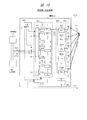
- FIG. 2 shows a detailed configuration example of the transmission / reception method and the system of the first embodiment.
- the receiving unit on the transmitting station 1 side and the transmitting unit on the receiving station 2 side are omitted.
- the characteristics of the four propagation paths from one antenna on the transmitting side to the four antennas on the receiving side cannot be said to be independent of each other.
- the transmitting side antenna train and the receiving side antenna train face each other, the propagation delay times in their propagation paths are almost equal. If there are few reflectors in the vicinity of them, the propagation delay effect of the reflected wave is also low, and the cross-correlation approaches 1.
- the transmission / reception method and system of the first embodiment of FIG. 2 also use such a diagonal propagation path. Therefore, this transmission / reception system is provided with 16 pseudo propagation paths.
- the pseudo-propagation path characteristic device 101 and the pseudo-propagation path characteristic analysis extraction device 108 of FIG. 2 each include 16 pseudo-propagation paths. This transmission / reception system uses these pseudo-propagation paths to multiply the radio waves (corresponding data signals) of each actual propagation path by the pseudo-propagation path characteristics, which are the reinforcing characteristics for lowering the cross-correlation.
- the transmitting station 1 is a transmitting device such as a wireless base station
- the receiving station 2 is a receiving device such as a user terminal.
- the configurations of the baseband portion in the transmitting station 1 and the baseband portion in the receiving station 2 are shown as the main components, and the illustration of other existing components is omitted.
- examples of other components include a controller, a memory, a storage, a communication device of another communication interface, a display device, an input device, a battery, and the like.
- the transmitting station 1 includes a pseudo propagation path characteristic device 101, a MIMO transmitting device 102, a transmitting antenna unit 103 which is a transmitting side MIMO antenna unit, and a propagation path characteristic management unit 104.
- the propagation path characteristic management unit 104 is provided inside the baseband unit of the transmitting station 1, but in another embodiment, it may be provided outside the baseband unit.
- the receiving station 2 has a receiving antenna unit 106, a MIMO receiving device 107, a pseudo propagation path characteristic analysis extraction device 108, and a propagation path characteristic management unit 109, which are receiving side MIMO antenna units.
- the propagation path characteristic management unit 109 is provided inside the baseband portion of the receiving station 2, but in another embodiment, it may be provided outside the baseband portion.
- the propagation path characteristic management unit 104 of the transmission station 1 when the entire communication system is FDD (frequency division duplex), the frequency propagation path characteristic of the propagation path according to the transmission frequency is the partner station, that is, only on the reception station 2 side in FIG. Since it can be measured, a report is obtained from the propagation path characteristic management unit 109 of the receiving station 2.
- the transmitting station 1 transmits the SRS reference signal required for measurement according to the communication rules. Further, when the entire communication system is TDD (Time division duplex), mutual communication is performed at the same frequency. Therefore, the receiving station 2 side is made to transmit the SRS reference signal, and the transmitting station 1 side is measured to perform measurement control.
- the propagation path characteristic management unit 104 manages the measurement results.
- the bidirectional broken lines between the propagation path characteristic management unit 104 and the propagation path characteristic management unit 109 in FIG. 1 indicate the above process. If the propagation path characteristic management unit 104 or the propagation path characteristic management unit 109 has a high cross-correlation between the generated pseudo-propagation path characteristics, a new one is discarded and a new one is generated.
- the pseudo propagation path characteristic device 101 of the transmission station 1 receives transmission data groups D100, D200, D300, and D400 as a plurality of data to be transmitted from an upper layer such as a control processor.
- Each transmission data group consists of four pieces of data.
- the transmission data group D100 includes data D1, D2, D3, and D4 as four data.
- the transmission data group is a plurality of parallel and independent data groups.
- the pseudo propagation path device unit 1011 includes pseudo propagation paths PP11, PP12, PP13, and PP14.
- the pseudo propagation path device unit 1012 includes pseudo propagation paths PP21, PP22, PP23, and PP24.
- the pseudo propagation path PP11 is a circuit that superimposes the first pseudo propagation path characteristic on the input data D1.
- the pseudo propagation path PP12 is a circuit that superimposes the second pseudo propagation path characteristic on the input data D2.
- the pseudo propagation path PP13 is a circuit that superimposes a third pseudo propagation path characteristic on the input data D3.
- the pseudo propagation path PP14 is a circuit that superimposes the fourth pseudo propagation path characteristic on the input data D4.
- the pseudo-propagation path device unit 1011 combines and outputs the four outputs of the four pseudo-propagation paths PP11 to PP14 by addition or the like.
- the combined output D121 is supplied to the individual MIMO processing unit 1021.
- the four outputs from the four pseudo-propagation path devices are indicated by outputs D121, D122, D123, and D124.
- the MIMO transmitter 102 includes a plurality of individual MIMO processing units (4 in this example according to the number of antennas N), and is indicated by individual MIMO processing units 1021, 1022, 1023, 1024. Each output from the pseudo-propagation path characteristic device 101 is input to the individual MIMO processing units 1021, 1022, 1023, 1024 associated with each other, and each is subjected to MIMO processing.
- each MIMO processing of the four individual MIMO processing units is represented by ⁇ 1 to ⁇ 4.
- ⁇ is a function and has ( ⁇ , a, ⁇ , t) as variables. ⁇ indicates the angular frequency, a indicates the amplitude, ⁇ indicates the phase, and t indicates the time.
- Each signal after MIMO processing in each individual MIMO processing unit is sent to the corresponding transmitting antenna of the transmitting antenna unit 103, and each is transmitted as a radio wave.
- the signal after MIMO processing by the individual MIMO processing unit 1021 is sent to the transmitting antenna A1.
- the characteristics of each propagation path are shown as characteristics h11, h12, h13, h14, h21, h22, h23, h24, h31, h32, h33, h34, h41, h42, h43, h44.
- the characteristics of the propagation paths of the opposing antenna pairs are the characteristics h11, h22, h33, h44, and the other characteristics are the characteristics of the propagation paths on the diagonal line.
- the four individual MIMO processing units of the MIMO transmitter 102 perform MIMO processing corresponding to the characteristics h11, h22, h33, and h44 of the four opposing propagation paths.
- the pseudo-propagation path characteristics of these multiple pseudo-propagation paths are, in order from the pseudo-propagation path PP11 to PP44, ⁇ 11, ⁇ 12, ⁇ 13, ⁇ 14, ⁇ 21, ⁇ 22, ⁇ 23, ⁇ 24, ⁇ 31, ⁇ 32, ⁇ 33, ⁇ 34, ⁇ 41, ⁇ 42. , ⁇ 43, ⁇ 44.
- the generation of these plurality of pseudo-propagation path characteristics will be described later.
- the plurality of individual pseudo-propagation paths of each pseudo-propagation path device unit of the pseudo-propagation path characteristic device 101 obtain pseudo delay profile model information (in other words, pseudo-propagation path characteristic information) from the propagation path characteristic management unit 104.
- the transmission data group is placed on the transfer function of the plurality of pseudo-propagation paths of the four pseudo-propagation path device units of the pseudo-propagation path characteristic device 101.
- the four outputs (corresponding transmission data signals) of the pseudo-propagation path characteristic device 101 are supplied to the four MIMO processing units.
- a MIMO function is added to each output signal in each MIMO processing unit (in other words, it becomes a MIMO frame signal). After that, each signal is fed to the four transmitting antennas and transmitted as radio waves. These radio wave groups are received by the four receiving antennas of the receiving station 2.
- the receiving antenna B1 receives radio waves from the four transmitting antennas through the characteristics h11, h21, h31, and h41 of each of the four propagation paths.
- the receiving antenna B2 receives radio waves from the four transmitting antennas through the characteristics h12, h22, h32, and h42 of each propagation path.
- the receiving antenna B3 receives radio waves from the four transmitting antennas through the characteristics h13, h23, h33, and h43 of each propagation path.
- the receiving antenna B4 receives radio waves from the four transmitting antennas through the characteristics h14, h24, h34, and h44 of each propagation path.
- the reception signals from the four receiving antennas are input to the corresponding four MIMO receiving units of the MIMO receiving device 107.
- Each MIMO receiving unit 1071, 1072, 1073, 1074 performs MIMO analysis processing and generates each processing output D171, D172, D173, D174.
- Each MIMO analysis process of the four MIMO receivers is represented by the receiving side propagation path analysis functions ⁇ 1r to ⁇ 4r.
- the correspondence between the receiving side propagation path analysis functions ⁇ 1r to ⁇ 4r and the transmitting side propagation path characteristics h11 to h44 and the pseudo propagation path characteristics ⁇ 11 to ⁇ 44 is shown in the following equation A.
- the math symbol x indicates multi
- the data D100D1 corresponds to the data D1 in the transmission data group D100 of FIG.
- the receiving unit 1071, 1072, 1073, 1074 measures the propagation path characteristics based on the SRS reference signal described in FIG. 1, acquires and manages the characteristic data of ⁇ 1r, ⁇ 2r, ⁇ 3r, and ⁇ 4r, and succeeds the actual data. Used for signal extraction during the data transmission period.
- the SRS reference signal when the SRS reference signal is generated, the data groups D100D1 to D400D4 are set to a constant value based on the communication convention. That is, when the values of D100D1 to D400D4 are the same, the receiving unit 1071, 1072, 1073, 1074 can measure the propagation path characteristics of the following equation B.
- ⁇ 2r-srs ⁇ 21 * h21, ⁇ 22 * h22, ⁇ 23 * h23, ⁇ 24 * h24>
- ⁇ 3r-srs ⁇ 31 * h31, ⁇ 32 * h32, ⁇ 33 * h33, ⁇ 34 * h34>
- ⁇ 4r-srs ⁇ 41 * h41, ⁇ 42 * h42, ⁇ 43 * h43, ⁇ 44 * h44>
- the propagation path characteristic can be measured for each branch on the receiving side.
- the propagation path characteristic management unit 104 and the propagation path characteristic management unit 109 in FIG. 1 perform the control of these SRS reference signals and the management of the measured propagation path characteristic information. These four processing outputs are input to the four pseudo propagation path analysis blocks of the pseudo propagation path characteristic analysis extraction device 108.
- the four pseudo-propagation path analysis blocks are the pseudo-propagation path analysis blocks 1081, 1082, 1083, 1084.
- Each pseudo-propagation path analysis block further includes four pseudo-propagation path analysis extraction units.
- the pseudo-propagation path analysis block 1081 includes the pseudo-propagation path analysis extraction units PR11, PR12, PR13, and PR14.
- the pseudo-propagation path analysis block 1082 includes the pseudo-propagation path analysis extraction units PR21, PR22, PR23, and PR24.
- the four pseudo-propagation path analysis extraction units of the pseudo-propagation path analysis block 1081 analyze the processing output D171 using the corresponding pseudo-propagation path characteristics, and extract signals.
- the pseudo propagation path characteristic (corresponding pseudo delay profile model) used in the pseudo propagation path characteristic analysis extraction device 108 on the receiving side is the same replica as the pseudo propagation path characteristic used in the pseudo propagation path characteristic device 101 on the transmitting side. ..
- the pseudo-propagation path PP11 and the pseudo-propagation path analysis / extraction unit PR11 use the same pseudo-propagation path characteristic ⁇ 11.
- the four pseudo-propagation path analysis extraction units perform cross-correlation calculation with a pseudo-delay profile model that reinforces the characteristics h11, h21, h31, and h41 of the actual propagation path.
- the four pseudo-propagation path analysis extraction units perform cross-correlation calculation with a pseudo-delay profile model that reinforces the characteristics h12, h22, h32, and h42 of the propagation path.
- the four pseudo-propagation path analysis extraction units perform cross-correlation calculation with a pseudo-delay profile model that reinforces the characteristics h13, h23, h33, and h43 of the propagation path.
- the four pseudo-propagation path analysis extraction units perform cross-correlation calculations with a pseudo-delay profile model that reinforces the characteristics h14, h24, h34, and h44 of the propagation path.
- the pseudo-propagation path characteristic analysis extraction device 108 obtains reception data groups E100, E200, E300, and E400 as four reception data groups.
- the pseudo-propagation path analysis extraction block 1081 extracts data E1 to E4 and becomes the corresponding received data group E100. These data E1 to E4 correspond to the data D1 to D4 of the transmission data group D100 on the transmission station 1 side.
- the propagation path characteristics between the received signals received from each branch have sufficiently low cross-correlation due to the superposition of the pseudo propagation path characteristics.
- the signal group transmitted in this way shall be represented by the formula A.
- the MIMO receiver 1071 performs correlation extraction using the acquired four types of propagation path characteristics ⁇ 11 * h11, ⁇ 12 * h12, ⁇ 13 * h13, ⁇ 14 * h14> to obtain the data group of the following equation D.
- Equation D ⁇ D100 D1 x ⁇ 11 * h11, D200 D1 x ⁇ 12 * h12, D300 D1 x ⁇ 13 * h13, D400 D1 x ⁇ 14 * h14>
- This data group becomes the output D171 of the MIMO receiving unit 1071 and is supplied to the pseudo propagation path analysis block 1081 of the next stage.
- four pseudo-propagation path analysis extraction units PR11, PR12, PR13, and PR14 receive the output D171 in parallel.
- each pseudo-propagation path characteristic analysis extraction unit performs a correlation extraction calculation between the SRS reference signal measurement result data obtained by each and the data group shown in Equation D.
- the pseudo-propagation path analysis extraction unit PR11 uses the SRS reference signal measurement result data ⁇ 11 * h11 to perform a correlation calculation with the data group shown in the equation D as shown in the following equation E.
- ⁇ in the equation E is the result of the cross-correlation calculation with the signals from other branches h12, h13, and h14 having low cross-correlation, and if the pseudo-propagation path characteristics work well, ⁇ becomes almost zero. From the above, taking the pseudo-propagation path analysis extraction unit PR11 as an example, the data D1 obtained at the corresponding branch h11 can be extracted as the data E1.
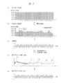
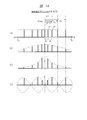
- FIG. 3 and 4 show a method of generating a pseudo delay profile model which is a pseudo propagation path characteristic.
- FIG. 3 shows a method of measuring the actual propagation path characteristics, the measured radio propagation path characteristics, and a pseudo propagation path model based on the delay profile derived based on the measured radio propagation path characteristics.
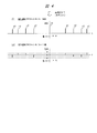
- FIG. 4 shows a method of generating the pseudo propagation path characteristics and a generated pseudo delay profile model as the second.
- the characteristic portion is modeled using the measurement results of the characteristics of the plurality of actual propagation paths to reduce the cross-correlation between the models. Use the deformed characteristics.
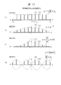
- FIG. 3 shows an SRS signal transmitted from one device (for example, receiving station 2).
- the horizontal axis of the graph shows the frequency (f) [Hz], and the vertical axis shows the intensity of the transmitted radio wave.
- the SRS signal is a signal for measuring the frequency characteristics of the radio wave propagation path, and the amplitude and phase are all the same within the used frequency band.
- One vertical line corresponds to the subcarrier.
- FIG. 3B shows a radio wave that takes into account the frequency characteristics of the actual propagation path as a radio wave that reaches the other device (for example, the transmitting station 1) that receives the SRS signal of (a).
- the dashed line frame corresponds to a resource block that bundles multiple subcarriers.
- the frequency is different between the downlink and the uplink. Therefore, for example, the transmitting station 1 causes the receiving station 2 on the other side to transmit an SRS signal immediately before data transmission.
- the frequency is the same for the downlink and the uplink. Therefore, for example, the transmitting station 1 measures the actual propagation path characteristics based on the SRS signal from the receiving station 2 on the other side, or causes the other side to send the result of measuring the actual radio wave path characteristics as a report.
- FIG. 3C shows the phase characteristics of the propagation path characteristics that are paired with the frequency characteristics of FIG. 3B.
- the horizontal axis of the graph is the phase [rad].
- the vertical axis is the range from ⁇ to ⁇ centered on 0.
- the delay profile characteristics of FIGS. 3D and 3 can be obtained. Be done.
- This frequency-time transform can be realized by the inverse FFT process (FFT: Fast Fourier Transform).
- FFT Fast Fourier Transform
- (D) represents the amplitude of the delay profile characteristic.
- the horizontal axis of the graph is time (t). In particular, the direct wave d0, the first reflected wave d1, the second reflected wave d2, the third reflected wave d3, and the fourth reflected wave d4 are shown.
- (E) represents the phase of the delay profile characteristic.
- the prominent components in the delay profiles (d) and (e) of FIG. 3 are extracted and simplified, that is, the modeled one is the pseudo-delay profile of (f) and (g) of FIG. Shown as a model.
- the models of (f) and (g) of FIG. 4 can be obtained.
- the models (f) and (g) in FIG. 4 have positive and negative components on the time axis by Z conversion on both sides. This conversion, in other words, modeling is necessary to correctly reflect the inversion of the plane of polarization caused by, for example, wall reflection due to the propagation of radio waves on the phase axis.
- the horizontal axis is time (t).
- the vertical axis is the intensity of radio waves.
- the vertical axis is the phase, which is a range from ⁇ to ⁇ centered on 0.
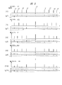
- FIG. 5 shows a method of reducing the cross-correlation of diagonal propagation paths in MIMO.
- FIG. 5 shows a pseudo-delay profile model corresponding to the 16 radio wave propagation paths of the 4 ⁇ 4 MIMO system of FIG. In FIG.
- the state of the delayed wave in each model is slightly different in time, and the phase is slightly different. In order to reduce the cross-correlation, it is effective to strengthen the delayed wave component.
- the frequency characteristics are changed, which is not preferable.
- the frequency characteristic of the delay profile characteristic is most affected by the delay wave interval when the delay wave interval is considered as the sampling time.
- the pseudo delay profile model of FIG. 5 is sent to the pseudo propagation path (pseudo propagation path characteristic device 101 and pseudo propagation path characteristic analysis extraction device 108) as it is.
- the pseudo propagation path prseudo propagation path characteristic device 101 and pseudo propagation path characteristic analysis extraction device 108
- the action of a large number of side lobe-like components existing around the time of the model wave can be reduced, and the cross-correlation becomes low.
- FIG. 6 shows a cross-correlation capability comparison for expansion using the plurality of pseudopropagation path characteristics (corresponding pseudo-delay profile models).
- the horizontal axis is the number of antennas between transmission and reception, and the vertical axis is the channel capacitance ave [bps / Hz].
- the straight line 601 shows the improvement effect in the case of the first method as the extension.
- the first method is the method described in Japanese Patent Application No. 2018-118353.
- the curve 602 shows the improvement effect in the case of the second method corresponding to the first embodiment.
- the channel capacitance increases in proportion to the number of antennas between transmission and reception.
- the channel capacitance increases in proportion to the square of the number of antennas between transmission and reception.
- the efficiency ⁇ in each case is as follows.
- ⁇ 2 ⁇ 2 4 / (T-2 ⁇ ).
- N ⁇ M there is a limitation of N ⁇ M between the number of transmitting and receiving antennas, but the provision of a new MIMO method in which the use of the pseudo propagation path characteristic according to the present invention does not impose this limitation. Is clearly possible. Further, according to the first embodiment, it is difficult to increase the number of transmission / reception antennas (for example, 16 ⁇ 16, 256 ⁇ 256, etc.), and even when the number of transmission / reception antennas is small (for example, 2 ⁇ 2), the pseudo propagation path is provided. The multiplexing used can improve frequency utilization efficiency and information transmission speed.
- the transmission / reception method and system of the second embodiment of the present invention will be described with reference to FIGS. 7 to 10.
- the transmission / reception method of the second embodiment corresponds to a modified example of the transmission / reception method of the first embodiment.
- the characteristics such as the transmission speed in the MIMO system shown in FIG. 6 described above have room for improvement from the viewpoint of frequency utilization efficiency and the like.
- the transmitted signal has a predetermined wide frequency band.
- the wideband signal propagated in the actual propagation path is not flat due to frequency selective fading.
- the 16 propagation paths of 4 ⁇ 4 MIMO in FIG. 2 have frequency portions that are insufficient for communication regardless of which one is adopted. Therefore, the expected value of the MIMO communication speed obtained by using the entire frequency band cannot be obtained as it is.
- the frequency bandwidth is 20 MHz
- the quadrature modulation is QPSK
- the MIMO level is 2 ⁇ 2 MIMO
- the transmission speed R is as follows. Become.
- BW indicates the bandwidth
- eff DSB indicates the frequency utilization efficiency by double-sided SSB modulation
- eff 16QAM-spectrum indicates the transmission rate efficiency in 16-value QAM modulation
- n MIMO indicates the transmission rate magnification in n ⁇ n MIMO.
- the wider the bandwidth the more affected by frequency selective fading, so that it becomes difficult to utilize the entire band of 20 MHz in the above equation.
- the second embodiment also solves such a problem.
- FIG. 7 shows a configuration example of a MIMO system as the transmission / reception system of the second embodiment.
- FIG. 7 shows a 2 ⁇ 2 MIMO portion of the MIMO system of FIG. 2 of the first embodiment to which an element peculiar to the second embodiment is added.
- a diversity mechanism 110 is added between the MIMO processing unit 102 and the transmitting antenna unit 103.
- the configuration of the MIMO receiving device 107 is different from that of the first embodiment, and the receiving side diversity processing unit 120 is added between the MIMO receiving device 107 and the pseudo propagation path characteristic analysis extraction device 108. Has been done.
- the two outputs of the individual MIMO processing units 1021 and 1022 on the transmitting station 1 side are the outputs SA1 and SA2.
- the two outputs SA1 and SA2 enter the diversity mechanism 110, and the adder 151 that generates the sum of the two outputs SA1 and SA2 (referred to as the sum signal SB1) and the difference between the two outputs SA1 and SA2 (difference signal SB2). Is supplied to and to the adder 152 that produces.
- the sum signal SB1 is transmitted from the transmitting antenna A1, and the difference signal SB2 is transmitted from the transmitting antenna A2.
- Each transmitted radio wave passes through the four propagation paths P11, P21, P12, P22 (corresponding characteristics h11, h21, h12, h22) between the 2 ⁇ 2 antennas in the actual propagation path P100, and is transmitted by the receiving antenna unit 106. It is received by the receiving antennas B1 and B2.
- the reception signals C1 and C2 in the receiving antenna unit 106 enter the MIMO receiving device 107, and are roughly classified into the MIMO processing units 107A and 107B, respectively.
- the MIMO processing unit 107A includes individual MIMO processing units 1071a and 1071b
- the MIMO processing unit 107B includes individual MIMO processing units 1072a and 1072b.
- the received signal C1 is input to the two individual MIMO processing units 1071a and 1071b
- the received signal C2 is input to the two individual MIMO processing units 1072a and 1072b.
- the corresponding actual propagation path characteristics h11, h12, h21, and h22 are transmitted from the receiving side MIMO control unit in the propagation path characteristic management unit 109 to the four individual MIMO processing units of the MIMO receiving device 107, respectively.
- each individual MIMO processing unit extracts the sum signal SB1 and the difference signal SB2 on the transmitting side from the signal of the received radio wave according to their respective characteristics.
- the sum signal SB1 on the characteristic h11 of the propagation path P11 reaches the first receiving antenna B1 from the transmitting antenna A1, and the difference signal SB2 on the characteristic h12 of the propagation path P12 arrives from the transmitting antenna A2.
- the sum signal SB1 mounted on the characteristic h21 and the difference signal SB2 mounted on the characteristic h21 reach the second receiving antenna A2 from the transmitting antennas A1 and A2.
- the individual MIMO processing unit 1071a can extract the sum signal SB1 from the first transmitting antenna A1 from the received signal C1 based on the characteristic h11.
- the individual MIMO processing unit 1071b can extract the difference signal SB2 from the second transmitting antenna A2 from the received signal C1 based on the characteristic h12.
- the individual MIMO processing unit 1072a can extract the sum signal SB1 from the first transmitting antenna A1 from the received signal C2 based on the characteristic h21.
- the individual MIMO processing unit 1072b can extract the difference signal SB2 from the second transmitting antenna A2 from the received signal C2 based on the characteristic h22.
- FIG. 8 shows a simulation example of frequency selective fading by multipath fading in a width of 15 MHz in the 5 GHz band.
- FIG. 8A shows the delay profile used in the simulation.
- the horizontal axis of the graph is the delay time [ns], and the vertical axis is the delayed wave relative power [dB].
- FIG. 8B shows a simulation result of frequency selective fading at two different positions by multipath fading in the 5 GHz band.
- the horizontal axis of the graph is frequency [GHz], and the vertical axis is relative power [dB].
- the spectrum 801 is the case of the first point, and the spectrum 802 is the case of the second point.
- the frequency width is about 15 MHz and the interval between fading peaks and valleys is about 2 MHz. Furthermore, it can be seen that the intensity attenuation appears about every 5 MHz.
- FIG. 8 an image of the effect of frequency selective fading of the four radio wave propagation paths as shown in FIG. 7 is drawn for each propagation path, and the frequency spectrum when signals passing through the four propagation paths are combined. Shows the image of.
- FIG. 9 shows the effect of removing frequency selective fading in 2 ⁇ 2 MIMO, which is the diversity of the second embodiment.
- the horizontal axis of the graph of FIG. 9 is frequency (f).
- (s) shows the frequency band characteristic on the transmitting side.
- (A) to (d) show frequency spectra affected by frequency selective fading due to the characteristics of each of the four propagation paths.
- (A) is due to the characteristic h11 of the propagation path P11
- (b) is due to the characteristic h12 of the propagation path P12
- (c) is due to the characteristic h21 of the propagation path P21
- (d) is due to the characteristic h22 of the propagation path P22.
- the receiving-side diversity processing unit 120 adds eight individual pseudo-propagating paths of the transmitting-side pseudo-propagating path characteristic device 101 from the four receiving outputs (outputs D21 to D24) from the MIMO receiving device 107.
- the signals D171 and D172 corresponding to the output D121 and D122 are obtained.
- These signals D171 and D172 are supplied to the pseudo propagation path characteristic analysis extraction device 108, and the same processing as in the first embodiment is performed.
- the pseudo-propagation path characteristic analysis and extraction device 108 includes pseudo-propagation path characteristic analysis and extraction units 1081 and 1082.
- the pseudo-propagation path characteristic analysis / extraction unit 1081 includes four pseudo-propagation path characteristic analysis / extraction units PR11 to PR14.
- Each pseudo-propagation path characteristic analysis extraction unit extracts a signal by analysis based on each pseudo-propagation path characteristic.
- the pseudo-propagation path characteristic analysis extraction unit 1081 acquires four data E1 to E4, and these are output (received data group) E100.
- FIG. 10 shows signal conversion for reducing frequency selective fading in a MIMO system and shows a method of synthesizing two orthogonal systems of signals.
- two orthogonal systems are considered on the x-axis and the y-axis.
- the vector signal V1 and the vector signal V2 on the x-axis are at the ⁇ / 4 rotation position on the x / y plane (x + y, ⁇ xy) / (xy, ⁇ x + y). ) Shows what it looks like from a plane.
- FIG. 10 shows signal conversion for reducing frequency selective fading in a MIMO system and shows a method of synthesizing two orthogonal systems of signals.
- two orthogonal systems are considered on the x-axis and the y-axis.
- the vector signal V1 and the vector signal V2 on the x-axis are at the ⁇ / 4 rotation position on the x / y plane (x + y, ⁇ xy) / (x
- each vector signal is as follows.
- V1 V1a + V1b
- V2 V2a + V2b
- U1 U1a + U1b
- U2 U2a + U2b.
- the vector moves on the rotation coordinate axis of ⁇ / 4.
- V1a U1a
- V1b U2a
- V2a U1b
- V2b U2b
- V1a + U2a V1a
- V1a-U2a U1. That is, when the two signals are added or made a difference on the receiving station 2 side, the original vector signal on the xy plane is restored.
- the receiving-side diversity processing unit 120 performs the undo processing in this way.
- the second embodiment has the following effects in addition to the effects of the first embodiment.
- a circuit for generating and reflecting the pseudo propagation path characteristics of the baseband portion is used in the transmission / reception system of the second embodiment. , Generates and transmits sum and difference signals between transmission signals. A circuit for restoring those signals is provided on the receiving station side.
- the complementary effect of frequency selective fading equivalent to the number of antennas can be realized, which is useful for further increasing the transmission speed.
- the beamforming function is a function that generates the focus of a radio wave beam at a desired point (reception point) by controlling the amplitude and phase of radio signals from each antenna using multiple antennas, but as an input condition. It is necessary to distribute the same signal to all antennas. Therefore, while MIMO operation in which a plurality of antennas can be used individually can transmit a plurality of data at the same time, only a single data can be transmitted at the same time during beamforming.
- the main separation and parallelization of communication paths is a separation and parallelization between a control signal system (C: Control signal / data) and a user data system (U: User signal / data), which is called CU separation.
- C Control signal / data
- U User signal / data
- SRS SRS reference signal
- the broadcast signal BCCH: Broadcast Control Channel
- random access signal RACH: Random Access CHannel
- PDSCH Physical Downlink Shared Channel
- PDCCH Physical Downlink Shared Channel
- the beam transmission path is single, so that the signals required for the above-mentioned 5th generation mobile communication cannot be separated and parallelized.
- a method capable of solving such a problem is shown.
- the transmission / reception method of the third embodiment is a transmission / reception method for transmitting / receiving data between a transmission device having a plurality of (N) transmitting antennas and a receiving device having one or more receiving antennas. It has a beamforming transmission function including a plurality of (N) transmitting antennas, a beamforming transmission circuit and a beam control unit, and the receiving device has a beamforming receiving function including a receiving antenna and a beamforming receiving circuit.
- This is a method of transmitting and receiving data by beamforming to and from a receiving device.
- the beamforming transmission function is a function of transmitting as a radio wave group constituting a beam from a plurality of (N) transmitting antennas based on one piece of data.
- the function of the beam control unit includes a function of performing propagation control for focusing the beam at a desired receiving point based on the characteristics of a plurality of actual propagation paths between the plurality of (N) transmitting antennas and receiving antennas. ..
- the beamforming reception function is a function of receiving a signal group corresponding to one data on the transmitting side from a radio wave group of a beam received by a receiving antenna.
- This transmission / reception method has the following generation step, creation step, transmission step, reception step, and extraction step.
- the generation step is a step in which the transmitting device or the receiving device generates the characteristics of a plurality of pseudo propagation paths between the plurality of (N) transmitting antennas and the receiving antennas.
- the creation step is a transmission target in which the transmission device includes at least a first data group (for example, I data) and a second data group (for example, J data) as a plurality of data groups of different types.
- Multiple (I + J) outputs in which each data in a certain parallel and independent plurality (for example, I + J) data is individually placed on the pseudo propagation path corresponding to each characteristic in the characteristics of the plurality (I + J) pseudo propagation paths.
- the transmission step is performed from a plurality of (N) transmission antennas in which the transmission device controls the propagation characteristics so as to focus on a desired reception point by a beamforming transmission function based on one transmission data / transmission signal.
- the receiving step is a step in which the receiving device receives a signal from the radio wave group arriving in the beam state by the beamforming receiving function including the receiving antenna.
- the receiving device converts the received signal into the characteristics of the plurality of (I + J) pseudo-propagation paths based on the analysis of the characteristics of the plurality of (I + J) pseudo-propagation paths corresponding to the transmitting side.
- This is a step of extracting a plurality of data corresponding to a plurality of parallel and independent (I + J) data including a plurality of data groups having different types.
- the current beamforming technology can be applied to the transmission step and the reception step.
- the plurality of data groups having different types are data groups in different planes, different bearers, different channels, different slices, different band control service types, or communications with different urgency on the protocol stack, or control / management. It is a data group of a system signal and an application system signal.
- Different band control service types include band control or service types such as GBR (guaranteed bit rate), CBR (constant bit rate), VBR (variable bit rate), ABR (Avilable bit rate), and UBR (unspecified bit rate). ..
- FIG. 11 shows the configuration of a beamforming system as the transmission / reception method and system of the third embodiment.
- the transmitting station 1 is a transmitting device such as a wireless base station
- the receiving station 2 is a receiving device such as a user terminal.
- the transmitting station 1 has a plurality of pseudo-propagation path characteristic devices 301, a beamforming control circuit 302, a transmitting antenna section 303, and one or more propagation path characteristic management sections 304 in a baseband section (not shown) on the transmitting side.
- a beam control unit 305 etc.
- the beamforming control function is composed of a beamforming control circuit 302, a transmitting antenna unit 303, and a beam forming unit 305.
- the plurality of pseudo-propagation path characteristic devices 301 include, for example, a pseudo-propagation path characteristic device 301A and a pseudo-propagation path characteristic device 301B as two pseudo-propagation path characteristic devices.
- One or more propagation path characteristic management units 304 include, for example, two propagation path characteristic management units 304A and a propagation path characteristic management unit 304B.
- two pseudo-propagation path characteristic devices are provided in the baseband portion on the transmission side in one transmitting station 1, but the present invention is not limited to this, and three or more pseudo-propagation path characteristic devices and corresponding devices are provided. It is also possible to have a configuration including a propagation path characteristic management unit.
- the pseudo propagation path characteristic device 301A includes a distributor 311A that supplies data DA1, DA2, ..., DAI as a plurality of (referred to as I) data that is a data group to be transmitted (for example, the first transmission data group), and theirs. It has a plurality of (I) pseudo-propagation paths PA1, PA2, ..., PAI corresponding to the plurality of (I) data.
- the pseudo propagation path characteristic device 301B is a distributor 311B that supplies data DB1, DB2, ..., DBJ as a plurality of (referred to as J) data that is a data group to be transmitted (for example, a second transmission data group).
- the signal / data D31 is input to the distributor 311A from the communication path NW31.
- the signal / data D32 is input to the distributor 311B from the communication path NW32.
- the communication paths NW31 and NW32 are communication paths or networks in the transmitting station 1, and examples of implementation include optical fibers. It should be noted that it has at least two communication paths NW31 and NW32, but the present invention is not limited to this, and three or more communication paths may be connected to the pseudo propagation path characteristic device 301.
- the receiving station 2 includes a receiving antenna unit 306, one or more pseudo-propagation path characteristic analysis / extraction devices 307, and a propagation path characteristic management unit 309 in a baseband unit (not shown).
- the pseudo-propagation path characteristic analysis and extraction device 307 includes, for example, two pseudo-propagation path characteristic analysis and extraction devices, a pseudo-propagation path characteristic analysis and extraction device 307A and a pseudo-propagation path characteristic analysis and extraction device 307B.
- the propagation path characteristic management unit 309 includes a propagation path characteristic management unit 309A and a propagation path characteristic management unit 309B as two propagation path characteristic management units.
- the pseudo-propagation path characteristic analysis extraction device 307A includes a plurality of (I) pseudo-propagation path characteristic analysis extraction circuits (PC1 to PCI) connected to the receiving antenna unit 306 (reception antenna B1) and an aggregate connected to them. It has 312A and.
- the pseudo-propagation path characteristic analysis / extraction device 307B includes a plurality of (J) pseudo-propagation path characteristic analysis / extraction circuits (PD1 to PDJ) and an aggregate 312B connected to them.
- routes / communication lines there are roughly two routes / communication lines as routes / communication lines for transmitting / receiving signals / data via beamforming.
- One is the first communication line and the other is the second communication line.
- the first communication line is a route that uses the communication path NW31, the pseudo-propagation path characteristic device 301A, the pseudo-propagation path characteristic analysis / extraction device 307A, and the communication path NW33.
- the second communication line is a route that uses the communication path NW32, the pseudo-propagation path characteristic device 301B, the pseudo-propagation path characteristic analysis / extraction device 307B, and the communication path NW34.
- a plurality of types of data are transmitted through these plurality (two) paths according to the use of signal separation and parallelization such as CU separation.
- the first data group can be control plane data in CU separation
- the second data group can be user plane data.
- the transmission data (first data D31 and second data D32) on the transmission station 1 side are supplied from the communication path NW31 and the communication path NW32 to the corresponding distributors 311A and 311B, respectively, in parallel and independently by distribution. It becomes a plurality of data groups of.
- control plane data is supplied as the first data D31 from the communication path NW31
- user plane data is supplied as the second data D32 from the communication path NW32.
- the first transmission data group DA output from the distributor 311A based on the first data D31 is composed of a plurality of (I) data (data DA1, DA2, ..., DAI).
- the second transmission data group DB output from the distributor 311B based on the second data D32 is composed of a plurality of (J) data (data DB1, DB2, ..., DBJ).
- Each data of the first transmission data group DA (DA1 to DAI) and the second transmission data group DB (DB1 to DBJ) reflects the pseudo propagation path characteristics in the corresponding pseudo propagation path characteristic devices 301A and 301B, respectively.
- Each data of the first transmission data group DA (DA1 to DAI) is placed on the transfer function of each pseudo propagation path in the plurality of pseudo propagation paths PA (PA1 to PAI) corresponding to the number of data (I). Be done.
- Each data of the second transmission data group DB (DB1 to DBJ) is placed on the transfer function of each pseudo propagation path in the plurality of (J) pseudo propagation paths PB (PB1 to PBJ) corresponding to the number of data (J). Be done.
- the characteristics of a plurality of (for example, I + J) pseudo-propagation paths are generated and set independently of the characteristics of the actual propagation path P300, assuming that their cross-correlation is sufficiently low.
- the plurality of (I) pseudo-propagation paths PA are referred to as the first group, and the plurality of (J) pseudo-propagation paths PB are referred to as the second group.
- a plurality of (I) pseudo-delay profile models having low cross-correlation are set in the plurality (I) pseudo-propagation path PAs of the first group by the propagation path characteristic management unit 304A.
- a plurality of (J) pseudo delay profile models having low cross-correlation are set by the propagation path characteristic management unit 304B.
- a plurality of pseudo-propagation paths PA and a plurality of (J) pseudo-propagation paths PB are combined so that their cross-correlation is low.
- a pseudo-delay profile model of (I + J) is set.
- the two propagation path characteristic management units 304A and 304B may be combined into one.
- outputs (output signals) OA from a plurality of pseudo-propagation paths PA of the pseudo-propagation path characteristic device 301A and a plurality (J) from a plurality of (J) pseudo-propagation paths PB of the pseudo-propagation path characteristic device 301B.
- a plurality of (I + J) outputs including the output (output signal) OB of the above are combined into one output (output signal) D301.
- This synthesis can be realized by digital processing such as addition and modulation.
- the output signal D301 is a signal on which a plurality of types (for example, two types) of data (for example, a first data group and a second data group) are superimposed in CU separation or the like.
- the beamforming control circuit 303 includes circuits 3021, 3022, ..., 302N as a plurality of (N) beamforming circuits corresponding to a plurality of (N) transmitting antennas of the transmitting antenna unit 303.
- the beamforming control circuit 302 Based on the control from the beam control unit 305, the beamforming control circuit 302 performs control such as amplitude phase adjustment for each individual antenna element of the transmission antenna unit 303 for one output signal D301, and each after control.
- the signal is supplied to each corresponding antenna element (antennas A1 to AN).
- Control processing such as amplitude phase adjustment in each beamforming circuit is shown by functions ⁇ 1 to ⁇ N.
- the beam control unit 305 has a function of controlling the propagation characteristics so as to focus on a desired receiving point by beamforming based on the characteristics of the actual propagation path P300 between the plurality of transmitting antennas and the receiving antennas. is there. At least one of the transmitting station 1 and the receiving station 2 measures the characteristics of the actual propagation path P300.
- the beam control unit 305 acquires measurement information (including frequency and phase characteristic information) of the characteristics of the actual propagation path P300 through the wireless line 313, and based on the measurement information, the actual propagation control for beamforming control. Arithmetic processing (precoding with the current technology) for flattening and focusing the frequency characteristics of the propagation path P300 is performed.
- the beam control unit 305 sets and controls each circuit of the beamforming control circuit 302 based on the calculation result.
- the beamforming control circuit 302 controls the amplitude and phase of the input data signal D301 according to the control.
- the transmitting antenna unit 303 has antennas A1, A2, A3, ..., AN as a plurality of (N) transmitting antennas (corresponding antenna elements) corresponding to the beamforming function.
- the actual propagation path P300 includes a plurality of propagation paths P51, P52, ..., P5N between the plurality of (N) antennas on the transmitting side and one or more antennas on the receiving side.
- the characteristics of each propagation path are characteristics h51, h52, ..., H5N.
- the radio waves corresponding to each propagation path are designated as radio waves 21, 22, 23, 24, ..., 2N, and these are designated as radio wave group 20.
- the radio wave group 20 from the transmitting antenna unit 303 forms a predetermined beam, and the main beam reaches the antenna B1 of the receiving antenna unit 306 of the receiving station 2 and focuses as a receiving point. ..
- the receiving antenna unit 306 has at least one antenna B1 and may have a plurality of antennas.
- One antenna B1 receives radio wave groups 20 from a plurality of (N) antennas.
- the received signal D302 by the antenna B1 enters the plurality of pseudo propagation path characteristic analysis extraction devices 307 (307A, 307B).
- the plurality of pseudo propagation path characteristic analysis extraction devices 307 include, for example, two pseudo propagation path characteristic analysis extraction devices 307A and a pseudo propagation path characteristic analysis extraction device 307B as two pseudo propagation path characteristic analysis extraction devices.
- the pseudo-propagation path characteristic analysis extraction device 307A is used as a plurality of (I) pseudo-propagation path characteristic analysis extraction unit (extraction circuit) PCs corresponding to the number of data (I) of the first communication line, such as extraction circuits PC1, PC2, ... , PCI and agglomerator 312A.
- the pseudo-propagation path characteristic analysis extraction device 307B is used as a plurality of (J) pseudo-propagation path characteristic analysis extraction unit (extraction circuit) PDs corresponding to the number of data (J) of the second communication line, and the extraction circuits PD1, PD2, ... , PDJ and aggregator 312B.
- the number of extraction circuits PCs and PDs (I, J) corresponds to the number of pseudo propagation paths (corresponding models) (I, J) of the data group on the transmitting side and the pseudo propagation path characteristic device 301.
- a plurality of (I) pseudo-delay profile models having low cross-correlation are set in the plurality (I) extraction circuit PCs of the pseudo-propagation path characteristic analysis extraction device 307A from the propagation path characteristic management unit 309A.
- These plurality (I) pseudo-delay profile models are the same replicas of the plurality (I) pseudo-propagation path characteristics (corresponding model) used in the transmission-side pseudo-propagation path characteristic device 301A.
- the pseudo delay profile model of the plurality (J) having low cross-correlation is set by the propagation path characteristic management unit 309B.
- These plurality (J) pseudo-delay profile models are the same replicas of the plurality (J) pseudo-propagation path characteristics (corresponding model) used in the transmission-side pseudo-propagation path characteristic device 301B.
- a plurality of (I + J) pseudo-delay profile models are set so that the cross-correlation is low even when the pseudo-propagation path characteristic analysis extraction devices 307A and 307B are combined as a whole.
- the two propagation path characteristic management units 309A and 309B may be combined into one.
- Each extraction circuit of the pseudo propagation path characteristic analysis extraction device 307A and 307B performs cross-correlation calculation with the pseudo delay profile model for each extraction circuit for the received signal D302. As a result, each extraction circuit extracts the data carried on the corresponding pseudo-propagation path.
- the extraction circuit PC1 extracts the data EA1 by performing analysis and extraction processing on the received signal D302 using the first model among the plurality of (I) models.
- the data EA2, ..., EAI are extracted from the extraction circuits PC2, ..., PCI.
- the data group extracted from the plurality of extraction circuits PCs (PC1 to PCI) of the pseudo propagation path characteristic analysis extraction device 307A is referred to as the first reception data group EA (EA1 to EAI).
- the first received data group EA is a data group having contents corresponding to the first transmitted data group DA (DA1 to DAI).
- the data group extracted from the extraction circuits PD (PD1 to PDJ) of the plurality (J) of the pseudo propagation path characteristic analysis extraction device 307B is referred to as the second reception data group EB (EB1 to EBJ).
- the second received data group EB is a data group having contents corresponding to the second transmitted data group DB (DB1 to DBJ).
- the first received data group EA (EA1 to EAI) from the extraction circuit PCs of the plurality (I) of the pseudo propagation path characteristic analysis extraction device 307A are aggregated into one received data D33 by the aggregate 312A, and the communication path NW33. Connected to and output.
- the second reception data groups EB (EB1 to EBJ) from the extraction circuits PD of the plurality (J) of the pseudo-propagation path characteristic analysis extraction device 307B are aggregated into one reception data D34 by the aggregate 312B, and the communication path NW34. Connected to and output.
- the communication path can be used as follows.
- the communication path NW31 and the communication path NW33 are used as user data communication lines, and in the receiving station 2 which is a terminal, the communication path NW33 is terminated at the user plane receiving portion to accompany, for example, an 8K high-quality image providing service.
- a user plane bearer for audio and a user plane bearer for video are connected to an 8K high-quality image decoder to provide a user with an 8K high-quality image service.
- the communication path NW32 and the communication path NW34 are used as control signal communication lines, and in the receiving station 2, the communication path NW34 is used as a control plane bearer at the control plane receiving portion, for example, a default bearer and a band guarantee (default bearer). GBR: guaranteed bit rate) Terminates the control plane such as control, and controls the communication of the terminal.
- the propagation path characteristic management unit 304 (304A, 304B) on the transmitting station 1 side has the characteristics of the actual propagation path P300 obtained by the plurality of propagation path characteristic management units 309 (309A, 309B) on the receiving station 2 side by the SRS signal. Measurement information (frequency characteristics or delay profile information) is obtained through the wireless line 313.
- the wireless line 313 is a communication line in which a signal is transmitted from the receiving station 2 (for example, a user terminal) side to the transmitting station 1 (for example, a base station) through the actual propagation path P300.
- the receiving station 2 for example, a user terminal
- the transmitting station 1 for example, a base station
- the downlink communication from the transmitting station 1 to the receiving station 2 is discussed, it is shown as a communication path that is intentionally separated from the actual propagation path P300 of the communication.
- the wireless line 313 corresponds to the communication path for control between the propagation path characteristic management units 104 and 109 described in the first embodiment (FIG. 1), and exchanges the actual characteristic measurement information and the pseudo propagation path characteristic device. It is used for exchanging which model is set for each of 301 and the pseudo propagation path characteristic analysis extraction device 307.
- the propagation path characteristic management unit 304 uses a model generated independently of the characteristics (measured values) of the actual propagation path P300 for setting the pseudo propagation path of the pseudo propagation path characteristic device 301 and the like.
- the beamforming control circuit 302 identifies the position of the receiving station 2 by the pilot signal or the SRS signal from the receiving station 2. Based on the control from the beam control unit 305, the beamforming control circuit 302 has an amplitude and a phase so that the main beam is focused on the receiving station 2 on a plurality of (N) beamforming circuits (circuits 3021 to 302N). Gives control information for.
- the propagation path characteristic management unit 304 (304A, 304B) stores a plurality of models (pseudo-delay profile models) obtained by the pseudo propagation path model generation method described later in the storage DB.
- the pseudo propagation path characteristic device 301A is set in each pseudo propagation path (PA1 to PAI) with reference to the DB model of the propagation path characteristic management unit 304A.
- the DB model of the propagation path characteristic management unit 304A and the DB model of the propagation path characteristic management unit 304B do not overlap with each other, and a plurality of models including them have high cross-correlation. It is managed so that it does not exist.
- the pseudo-propagation path characteristic device 301 (301A, 301B) of the transmitting station 1
- separate data (first) is used by using a model of a plurality of (I, J) pseudo-propagation paths having low cross-correlation.
- the outputs (OA, OB) of each pseudo-propagation path carrying the transmission data group DA and the second transmission data group DB) are combined into one output signal D301.
- This one output signal D301 meets the input conditions of the beamforming function, which is possible if it is one transmission signal.
- the transmitting station 1 Based on the output signal D301, the transmitting station 1 emits as a radio wave group 20 from a plurality of (N) transmitting antennas whose propagation characteristics are controlled so as to focus on a desired receiving point by a beamforming function, and serves as a receiving point. It reaches the antenna B1 of the target receiving station 2.
- the pseudo-propagation path characteristic analysis / extraction device 307 on the receiving station 2 side uses a plurality of (I, J) pseudo-propagation path models same as those on the transmitting side. Each data of I, J) data can be separated and extracted.
- the reliability of communication can be further easily improved.
- FIG. 12 shows the realization of CU separation as an example of using the beamforming function in the transmission / reception method and the system of the third embodiment.
- the upper part of FIG. 12 shows the CU separation by beamforming, and the lower part shows the communication line state as a conceptual image.
- the transmitting station 1 is a base station and the receiving station 2 is a user terminal.
- a plurality of data (for example, x Data # 11 to # 1x and y data Data # 21 to Data # 2Y) are placed on a plurality of (x + y) pseudo-propagation paths by the above-mentioned mechanism. It is superimposed and combined with one output signal D301, and the radio wave group 20 by beamforming is transmitted from the plurality of antennas A1 to AN of the transmitting antenna unit 303.
- the number of data (I, J) in the first transmission data group DA and the second transmission data group DB in FIG. 11 described above is not limited to a plurality, and can be set to 1, for example, the control plane data 310. May be one. Depending on the application, for example, the number of parallel data (x) of the user plane data 320 is expected to be larger than the number of parallel data (y) of the control plane data 310.
- a first communication line and a second communication line are provided as a plurality of communication lines (in other words, a virtual communication path) superimposed on beamforming, and the first communication line is medium-speed and highly reliable communication. It is used to transmit the required control plane data (Control plane data) 310, and the second communication line is used to transmit the user plane data (User plane data) 320 that requires ultra-high speed communication. That is, CU separation can be realized by using a plurality of pseudo propagation paths during beamforming. When looking at the beam at a certain point in time, the control plane data of the first communication line and the user plane data of the second communication line are superimposed on the beam. Depending on the transmission status, only one of the control plane data and the user plane data may be included at each time point.
- FIG. 12 shows the service status of eMBB (enhanced Mobile Broadband) in which the user terminal (reception station 2) requests ultra-high-speed communication on the order of Gbps.
- eMBB enhanced Mobile Broadband
- the control signals (control plane data) scattered in the OFDM frame can greatly hinder the pursuit of ultra-high speed.
- the control signal requires highly reliable communication at a medium speed.
- high multi-level modulation such as 16QAM or 64QAM
- QPSK highly reliable modulation
- the transmission speeds and signal error rates of the eMBB (user plane data) and the control signal (control plane data) are contradictory to each other, and mixing within the same frame is not desirable for both.
- the routes are different from each other due to the network structure, and the user plane data is connected by the exchange network, that is, the network from the S-GW (Serving gateway) of the core network work, while the control signal is MME ( Since it is connected by the network from MobileManagementEntity), it is desirable to separate it on the wireless line in the 5th generation.
- MIMO having a large number of propagation paths
- different communication frames can be provided by allocating the communication transmission paths, and the optimum communication form can be realized for each.
- the conventional beamforming function since there is a condition that the same one signal is input, it is impossible to mix or superimpose different types of communication frames on the same beam.
- the third embodiment as shown in the figure, a plurality of communications in which different types of communication frames, for example, control plane data 310 and user plane data 320, are mixed or superimposed on the same beam even during beamforming operation. It is clear that the line status can be provided. In the third embodiment, it is possible to provide a plurality of line states similar to those in MIMO operation even during beamforming, and as shown in the figure, for example, network operation in line with CU separation can be realized.
- the control plane data 310 from the MME of the EPC core network is mounted on the first communication line 311 to perform medium-speed and high-reliability communication.
- EPC evolved Packet Core
- MME Mobility Management Entity
- S-GW Session Management Entity
- the provision of a plurality of communication line states at the time of beamforming according to the third embodiment can correspond not only to the CU separation but also to the following examples of various uses and applications. That is, examples of other applications include dissimilar bearer provision, network slicing, SRS signal separation, ETWS separation, parallel transmission of control / management signals during microwave power transmission, separation of automatic operation control signals, and the like.
- examples of other applications include dissimilar bearer provision, network slicing, SRS signal separation, ETWS separation, parallel transmission of control / management signals during microwave power transmission, separation of automatic operation control signals, and the like.
- In providing different types of bearers it is possible to provide a plurality of different types of bearers (virtual transmission lines).
- Network slicing allows the provision of multiple different types of slices in the front hole of a network.
- the SRS signal separation the SRS signal and the like can be separated into a specific pseudo-propagation path.
- ETWS separation it is possible to maintain normal communication during emergency communication, that is, when ETWS
- FIG. 13 shows a method of generating a plurality of pseudo delay profile models (corresponding pseudo propagation path characteristics) according to the third embodiment.
- the transmitting station 1 or the receiving station 2 sets the characteristics of a plurality of pseudo propagation paths with a plurality of transmitting antennas and one or more based on a preset delay profile model. It is generated independently of the characteristics of the actual propagation path to and from the receiving antenna of.
- (A), (b), (c), and (d) of FIG. 13 show each of the four models having low cross-correlation, and are referred to as the first model to the fourth model for explanation.
- the horizontal axis is the time (t) having positive and negative, and the vertical axis is the amplitude.
- the function shown in FIG. 13 is an example of an envelope used to generate a pseudo-delay profile used in the third embodiment. In each case, the amplitude is based on 1, and the portion shown by the solid line constitutes the delayed wave.
- Functions that follow this principle are functions that are axisymmetric to any origin and that are orthogonal to each other, that is, independent functions. These plurality of functions can be used as a plurality of pseudo propagation path characteristics (corresponding models). This is because, due to the beamforming function, the propagation path characteristics of the actual propagation space are uniquely in a nearly perfect conductor state, and the constraints imposed on the pseudo-delay profile are almost equal.
- the first model of (a) shows a group of delayed waves having a constant amplitude in the range up to time t 0 .
- the amplitudes of the delayed waves 1221, 1222 and the like are decreasing in each of the positive and negative directions.
- the time interval K of the delayed wave group is constant, but in this case, the time interval K is the sampling time, and the power is concentrated in a specific frequency range. If the frequency bandwidth is wide, the delay wave groups need to be placed at non-uniform intervals.
- FIG. 14 similarly shows a case where the time interval of the delayed wave is made non-uniform by extending it in proportion to the time t with respect to FIG. 13.
- T at (a is a coefficient).
- the delay time of the delay wave w1 is T1
- the delay time of the delay wave w2 is T2.
- the time interval from the reference to the delay wave w1 is k1
- the time interval from the delay wave w1 to the delay wave w2 is k2, and k1 ⁇ k2.
- FIG. 15 similarly shows the case where the positions of the delayed waves are not aligned with each other on the time axis.
- (A) of FIG. 15 is the same as (a) of FIG. 14, and (b), (c), and (d) of FIG. 15 are relative to (b), (c), and (d) of FIG. , The position of the delayed wave on the time axis is different.
- the cross-correlation of the example of the model group of FIG. 14 is lower than that of the model group of FIG. Further, the example of FIG. 15 can dramatically lower the cross-correlation than the example of FIG. However, the upper limit of the frequency band is dominated by the portion having the shortest time interval, so a limit is set.
- the propagation path characteristic management unit 204 of FIG. 11 confirms the cross-correlation between the models of the plurality of pseudo-delay profile models, and confirms that each model can be Fourier transformed and accommodated within a predetermined frequency bandwidth. In the case of a model that does not satisfy such a predetermined condition, the propagation path characteristic management unit 204 discards the model and replaces it with a model modified so as to satisfy the predetermined condition.
- the above operation it is possible to generate a plurality of pseudo-delay profile models having low cross-correlation.
- the types and numbers of the plurality of pseudo delay profile models required by each pseudo propagation path of the pseudo propagation path characteristic device 301 and the pseudo propagation path characteristic analysis extraction device 307 of FIG. 11 are easily satisfied.
- the number is not infinite and has an upper limit.
- the upper limit of the number of pseudo-delay profile models will be described.
- the upper limit of the number of pseudo-delay profile models is determined by the condition that the time length of the pseudo-delay profile is sufficiently within the OFDM time interval, that is, the Cyclic Prefix (CP).
- the minimum delay wave interval time for setting the delay wave is determined by the time resolution of the FFT.
- FIG. 16 shows the frame structure of OFDM in the 4th generation mobile communication which is the basis of the 5th generation mobile communication, and particularly shows the CP (in other words, the guard interval) for accommodating the delayed wave.
- FIG. 16 corresponds to a frame in the case of the LTE standard and the FDD method.
- frame 1510 is an OFDMA frame.
- Frame 1511 is an OFDMA frame that precedes frame 1510
- frame 1512 is a subsequent OFDMA frame.
- CP1513 is a CP section for accommodating a delayed wave between the preceding frame 1511 and frame 1510
- CP1514 is a CP section for accommodating a delayed wave between the frame 1510 and the succeeding frame 1512. is there.
- Period (t t) 1517 is the OFDMA frame repetition period consists of a period of CP (t cp) 1516, the period of frame (t s) 1515 Metropolitan.
- the CP1513 and 1514 are designed so that the delayed wave groups arriving later than the main wave can be collectively FFT integrated.
- the OFDM parameters at 5 MHz size are the values shown in Table 1.
- the transmission bandwidth is 5 MHz
- the occupied bandwidth is 3.84 MHz
- the subframe time interval is 0.5 ms
- the subcarrier frequency interval is 15 kHz
- the sampling frequency is 15.36 MHz
- the FFT size is 512.
- the system frequency resolution of the OFDMA system consists of an occupied frequency bandwidth of 3.84 MHz and an FFT size of 512 or 15 kHz that decomposes it.
- the number of points on the time axis that can be identified by the time resolution is 36.
- the number of points (described as the number of sample points in the standard) is 144 because oversampling is performed four times, but from the viewpoint of frequency measurement, the number of 15 kHz subcarriers is 36 points or more. It does not become.
- the wave number of the delay profile of the pseudo propagation path model required by the present invention is, for example, 6, from these 36 points on the time axis, for example, the first point is fixed and the remaining 5 points are 35.
- the number of combinations selected from the points is the number of pseudo propagation path models.
- a method of generating a model in the time domain is shown, but based on the number of subcarriers in the frequency domain, the number of subcarrier points arranged on the frequency is, for example, 256 points, which is 1/2 of 512 points.
- the number of subcarrier points arranged on the frequency is, for example, 256 points, which is 1/2 of 512 points.
- n 512 P 256 , and a considerable number of models can be obtained.
- conversion is performed in the time domain, a delay profile whose time length is within the CP is selected, and a model having a low cross-correlation between models is selected for practical use.
- a certain pseudo-delay profile model can be represented.
- CSI channel state information
- a new index is provided for this purpose.
- the transmitting station 1 may extend the CSI, describe the pseudo propagation path characteristic information (information representing the corresponding model) to be used for the transmission data (corresponding frame) in the CSI, and notify the receiving station 2. it can.
- the receiving station 2 can grasp the model to be used in the analysis by referring to the pseudo propagation path characteristic information in the above CSI from the received signal.
- the multi-antenna system which plays a leading role in the fifth generation mobile communication, uses the mMIMO (massive MIMO) function for short-distance users and the beamforming function for long-distance users. This is said to play a role in compensating for the decrease in received power at the end of the cell (wireless communication area) in increasing the frequency used for speeding up communication.
- mMIMO massive MIMO
- the area of the focal area formed by the beam surely increases as the distance in the radial direction increases.
- the half width of the radiation angle at which the received power is 50% of the maximum value is 6.45 ° regardless of the frequency.
- the focus becomes sharper because the phase, delay time, and amplitude are controlled for each antenna element, so that the half width becomes narrower.
- there is a trade-off with sidelobe suppression and here we will consider using the numerical values of the array antenna.
- the elliptical area is about 150 m 2 . Since the target for 5th generation terminal capacity is 1 unit / m 2 , at least 150 terminals will be accommodated in this focal area.
- the network can be divided, and the operator and the MVNO can provide communication to each user terminal in the same beam.
- the transmission / reception method of the fourth embodiment is a transmission / reception method for transmitting / receiving data between a transmission device having a plurality of (N) transmitting antennas and each receiving device of a plurality of receiving devices having one or more receiving antennas. Therefore, the transmitting device has a beamforming transmitting function including a plurality of (N) transmitting antennas, a beamforming transmitting circuit, and a beam control unit, and the receiving device has a beamforming receiving function including a receiving antenna and a beamforming receiving circuit.
- This transmission / reception method includes a generation step, a creation step, a transmission step, a reception step, and an extraction step.
- the transmitter or one of the receivers has a plurality of (N) transmitter antennas and a plurality of receiver antennas.
- the transmitting device includes a plurality of (for example, two) data groups including a first data group (for example, K data) and a second data group (for example, L data) as a plurality of data groups of different types. Multiple data in parallel and independent multiple (for example, K + L) data to be transmitted to the receiving device are individually placed on the pseudo-propagation path corresponding to each characteristic in the characteristics of the plurality of (K + L) pseudo-propagation paths.
- the transmission step is a step in which the transmitting device transmits a radio wave group constituting a beam from a plurality of (N) transmitting antennas whose propagation characteristics are controlled by a beamforming transmission function based on one transmission data.
- the reception step is a step in which the receiving device (for example, the first receiving device) receives a signal from the radio wave group arriving in the beam state by the beamforming receiving function including the receiving antenna.
- the receiving device analyzes the characteristics of a plurality of (for example, K) pseudo-propagation paths related to the own machine among the characteristics of a plurality of (K + L) pseudo-propagation paths from the received signal. Is a step of extracting a plurality of data corresponding to the data group (for example, the first data group) of the destination of the own machine, which is included in the characteristics of the plurality of (K) pseudo-propagation paths related to the own machine.
- FIG. 17 shows the configuration of a beamforming system as the transmission / reception method and system of the fourth embodiment.
- This configuration differs from the configuration of the third embodiment (FIG. 11) in that there are a plurality of receiving stations 2 (user terminals) in the focal point (focal area) 3 of the beam, and communication on the transmitting station 1 side.
- the road NW41 and the communication road NW42 may have a degree of freedom to function independently.
- the transmitting station 1 is a transmitting device such as a wireless base station
- the receiving stations 2A and 2B are receiving devices such as a user terminal.
- the receiving station 2A is a first user terminal
- the receiving station 2B is a second user terminal.
- the transmission station 1 includes a plurality of pseudo-propagation path characteristic devices 401, a beamforming control circuit 402, a transmission antenna section 403, one or more propagation path characteristic management sections 404, a beam control section 405, and the like in the baseband section. ..
- the plurality of pseudo-propagation path characteristic devices 401 include, for example, a pseudo-propagation path characteristic device 401A and a pseudo-propagation path characteristic device 401B as two pseudo-propagation path characteristic devices.
- the propagation path characteristic management unit 404 includes, for example, a propagation path characteristic management unit 404A and a propagation path characteristic management unit 404B as two propagation path characteristic management units.
- the pseudo propagation path characteristic device 401A is a first characteristic device, and is a network termination that supplies multiple (K) parallel and independent data DA1, DA2, ..., DAK, which are the first transmission data group DA to be transmitted.
- the device 411A and a plurality of (K) pseudo-propagation paths PX1, PX2, ..., PXK corresponding to the number of data are provided.
- the pseudo propagation path characteristic device 401B is a second characteristic device, and is a network termination that supplies a plurality of parallel and independent (L) data DB1, DB2, ..., DBL which are second transmission data group DBs to be transmitted.
- the device 411B and a plurality of (L) pseudo-propagation paths PY1, PY2, ..., PYL corresponding to the number of data are provided.
- the network termination device 411A of the pseudo propagation path characteristic device 401A uses the communication path NW41 as input / output
- the network termination device 411B of the pseudo propagation path characteristic device 401B uses the communication path NW42 as input / output. It is possible to output data from the network termination device 411A to the communication path NW41.
- the numbers K and L in the fourth embodiment are numbers of concepts different from the numbers I and J in the third embodiment.
- the receiving station 2A includes a receiving antenna unit 406A including one or more receiving antennas, one or more pseudo propagation path characteristic analysis extraction devices 407A, and a propagation path characteristic management unit 409A in the baseband unit. ..
- the receiving station 2B includes a receiving antenna unit 406B including one or more receiving antennas, one or more pseudo propagation path characteristic analysis extraction devices 407B, and a propagation path characteristic management unit 409B in the baseband unit. ..
- the receiving antenna unit 406A includes, for example, the receiving antenna B1A.
- the receiving antenna unit 406B includes, for example, the receiving antenna B1B.
- the pseudo-propagation path characteristic analysis extraction device 407A is a first extraction device, and is an extraction circuit PU1 as a plurality (K) pseudo-propagation path characteristic analysis extraction unit (extraction circuit) PU corresponding to the first characteristic device on the transmitting side. Includes PU2, ..., PUK.
- the pseudo-propagation path characteristic analysis extraction device 407B is a second extraction device, and is an extraction circuit PV1 as a plurality (L) pseudo-propagation path characteristic analysis extraction unit (extraction circuit) PV corresponding to the second characteristic device on the transmitting side. Includes PV2, ..., PVL.
- transmission data is supplied from the communication path NW41 and the communication path NW42 to the network termination device 411A of the pseudo propagation path characteristic device 401A and the network termination device 411B of the pseudo propagation path characteristic device 401B. ..
- the network termination device 411A obtains a plurality of (K) parallel and independent data DA1 to DAK as the first transmission data group DA from the input data D41 from the communication path NW41.
- the network termination device 411B obtains a plurality of parallel and independent data DBs 1 to DBL as the second transmission data group DB from the input data D42 from the communication path NW42.
- a plurality of (K groups) pseudo-propagation paths PX (PX1 to PXK) of the pseudo-propagation path characteristic device 401A are provided with a plurality of pseudo-delay profile models having low cross-correlation as individual models from the pseudo-propagation path characteristic management unit 404A. Is set.
- a plurality of (L groups) pseudo-propagation paths PY (PY1 to PYL) of the pseudo-propagation path characteristic device 401B are subjected to a plurality of pseudo-propagation paths PY (PY1 to PYL) having low cross-correlation as individual models from the pseudo-propagation path characteristic management unit 404B.
- the delay profile model is set. Even in the total of the pseudo-propagation path PX and the pseudo-propagation path PY, a plurality of models having sufficiently low cross-correlation are set for the characteristics of the plurality of pseudo-propagation paths.
- Each data of the first transmission data group DA is placed on the transfer function of the corresponding pseudo propagation paths in the plurality of (K) pseudo propagation paths PX (PX1 to PXK) corresponding to the number of data in the pseudo propagation path characteristic device 401A. Is output (output signal) OX.
- the pseudo-propagation path PX1 causes the data DA1 to act on the first model.
- each data in the second transmission data group DB is transmitted in the pseudo-propagation path characteristic device 401B by the corresponding pseudo-propagation paths in the plurality of (L) pseudo-propagation paths PY (PY1 to PYL) corresponding to the number of data. It is put on the function and becomes the output (output signal) OY.
- the pseudo propagation path characteristic device 401 (401A, 401B) combines the plurality of (K, L) outputs OX and OY into one output (output signal) D401.
- One output signal D401 is supplied to the beamforming control circuit 4
- the beamforming control circuit 402 is subjected to one output signal D401 by the circuits 4021, 4022 ..., 402N, which are beamforming circuits, based on the control from the beam control unit 405. Controls such as amplitude phase adjustment (processing of functions ⁇ 1 to ⁇ N) are performed corresponding to each antenna (A1 to AN) of the transmitting antenna unit 403, and each signal after control is sent to each corresponding antenna element (A1 to AN). Supply to AN).
- amplitude phase adjustment processing of functions ⁇ 1 to ⁇ N
- the transmitting antenna unit 403 has the same configuration as that of the third embodiment.
- the transmitting station 1 transmits the radio wave group 20 constituting the beam from the transmitting antenna unit 403 as a result of the beamforming control based on the data D401 by the beamforming transmission function including the transmitting antenna unit 403.
- the main beam of the radio wave group 20 forms a focal point (focal area) 3 corresponding to the receiving point on the receiving side.
- the main beam reaches and focuses on the antenna B1A of the receiving antenna portion 406A of the receiving station 2A and the antenna B1B of the receiving antenna portion 406B of the receiving station 2B located in the focal point 3. Note that FIG.
- the radio wave group 20 particularly connects the focal point 3 to the antenna B1A of the receiving station 2A, and at the same time, the antenna B1B of the receiving station 2B is also included in the focal point 3.
- the receiving antenna unit 406 of each receiving station 2 has the same configuration as that of the third embodiment.
- the receiving station 2A receives the signal D402A from the radio wave group 20 by the beamforming receiving function including the receiving antenna unit 406A.
- the receiving station 2B receives the signal D402B from the same radio wave group 20 by the beamforming receiving function including the receiving antenna unit 406B.
- the signal D402A from the antenna B1A is input to the extraction circuits PU (PU1 to PUK) as the pseudo-propagation path characteristic analysis extraction unit of the plurality (K) of the pseudo-propagation path characteristic analysis extraction device 407A.
- the signal D402B from the antenna B1B is input to the extraction circuits PV (PV1 to PVL) as the pseudo-propagation path characteristic analysis extraction unit of the plurality (L) of the pseudo-propagation path characteristic analysis extraction device 407B.
- the number of extraction circuits (K, L) on the receiving side corresponds to the number of data on the transmitting side and the number of pseudo propagation paths.
- the number K and the number L may be the same or different.
- the plurality of extraction circuit PUs of the pseudo-propagation path characteristic analysis extraction device 407A have the same characteristics as the plurality (K) pseudo-propagation paths used in the pseudo-propagation path characteristic device 401A on the transmitting side from the propagation path characteristic management unit 409A. Multiple (K) pseudo-delay profile models that are replicas are set.
- the plurality of extraction circuits PV of the pseudo-propagation path characteristic analysis extraction device 407B are the same as the characteristics of the plurality (L) pseudo-propagation paths used in the pseudo-propagation path characteristic device 401B on the transmission side from the propagation path characteristic management unit 409B.
- a plurality of (L) pseudo-delay profile models that are replicas are set.
- Each extraction circuit PU (PU1 to PUK) of the pseudo-propagation path characteristic analysis extraction device 407A performs a cross-correlation calculation with a plurality of (K) pseudo-delay profile models corresponding to the received signal D402A, thereby performing a pseudo-propagation path. Extract the data contained in the characteristics. For example, the extraction circuit PU1 extracts data EA1 from the received signal D402A by analysis using the first model. As a result, the extraction circuit PA obtains the first reception data group EA (data EA1, EA2, ..., EAK) having the contents corresponding to the first transmission data group DA.
- each extraction circuit PV (PV1 to PVL) of the pseudo propagation path characteristic analysis extraction device 407B performs cross-correlation calculation with the corresponding plurality of (L) pseudo delay profile models for the received signal D402B. Extract the data included in the pseudo-propagation path characteristics. As a result, the extraction circuits PV (PV1 to PVL) obtain the second reception data group EB (data EB1, EB2, ..., EBL) having the contents corresponding to the second transmission data group DB.
- the beam control unit 405 on the transmitting station 1 side measures measurement information (frequency characteristics or frequency characteristics) of the characteristics of the actual propagation path P400 obtained by at least one of the propagation path characteristic management units 409 (409A, 409B) on the receiving station 2 side by the SRS signal. (Delay profile information) is obtained through the wireless line 413.
- the wireless line 413 is a line in which a signal is transmitted from the receiving station 2 side to the transmitting station 1 side through the actual propagation path P400 as in the third embodiment, but is intentionally shown separately from the actual propagation path P400. ..
- the beamforming unit 405 controls the beamforming control circuit 402 based on the characteristics of the actual propagation path P400.
- the beamforming control circuit 402 identifies the position of the receiving station 2 which is the communication target by the pilot signal or the SRS signal from the receiving station 2 (2A, 2B) which is the communication target.
- the main beam focuses on a plurality of (N) beamforming circuits (circuits 4021 to 402N) on the receiving station 2 (for example, two receiving stations 2A and 2B) to be communicated with. Amplitude and phase control information is given so as to connect.
- the propagation path characteristic management unit 404 (404A, 404B) stores a plurality of pseudo delay profile models obtained by the pseudo propagation path model generation method in the storage DB, as in the third embodiment.
- the pseudo propagation path characteristic device 401A is set in the pseudo propagation path PX with reference to the DB model of the propagation path characteristic management unit 404A.
- the DB model of the propagation path characteristic management unit 404A and the DB model of the propagation path characteristic management unit 404B are managed so as not to have duplication or high cross-correlation.
- the transmitting station 1 uses the pseudo-propagation path characteristic device 401 (401A, 401B) to mutually (for example, two) receive separate data (DA1 to DAK, DB1 to DBL) for the receiving stations 2.
- One output signal D401 is obtained by synthesizing them individually on a pseudo-propagation path using a plurality of (K + L) models having low correlation.
- One output signal D401 matches the input condition of the beamforming function.
- the transmitting station 1 Based on the output signal D401, the transmitting station 1 emits as a radio wave group 20 from a plurality of transmitting antennas by a beamforming function.
- two communication lines can be configured in the beam at this time, so that two transmission data groups (DA, DB) corresponding to the receiving station 2A and the receiving station 2B of the two destinations (destination) can be configured. Can be mixed at the same time.
- the focal point of the beam reaches the antenna B1A of the receiving station 2A, which is one of the transmitting destinations, and also reaches the antenna B1B of the receiving station 2B, which is the other transmitting destination.
- the receiving station 2A uses the pseudo-propagation path characteristic analysis and extraction device 407A to separate and extract a plurality of (K) data addressed to the own machine from such a beam by using the same plurality of (K) models as the transmitting side.
- the receiving station 2B uses the pseudo-propagation path characteristic analysis and extraction device 407B to obtain a plurality of (L) data addressed to the own machine from the same beam using a plurality of (L) models different from those on the receiving station 2A side. It can be separated and extracted to obtain a second received data group EB.
- the transmitting station 1 side when the transmitting station 1 side handles a plurality (for example, K + L) models of pseudo-propagation path characteristics in the entire pseudo-propagation path characteristic device 401 (401A, 401B), a plurality of (for example, two) receptions are received.
- Each receiving station 2 in the station 2 may handle a number of models smaller than the number of models on the transmitting side in the pseudo propagation path characteristic analysis extraction device 407 (407A, 407B).
- the receiving station 2A handles a plurality of (K) models related to its own device.
- the receiving station 2A analyzes the received signal by beam forming with the pseudo-propagation path characteristic analysis and extraction device 407A using a plurality of (K) models related to the own machine, and the plurality (K + L) mounted on the received signal. ), The data group (EA) of the destination of the own machine is extracted.
- the receiving station 2A does not have a plurality of (L) models for the other receiving station 2B, and does not extract the data group (EB) of the destination of the other receiving station 2B. This is the same when viewed from the receiving station 2B.
- the receiving station 2 side When the receiving station 2 side generates a model of the pseudo propagation path characteristic at the time of communication with the plurality of receiving stations 2 as described above, the plurality of receiving stations 2 included in the focal area 3 of the beam. Any one of the receiving stations 2 may be generated.
- the reliability of communication can be further easily improved.
- FIG. 18 shows the realization of multi-user communication (in other words, a multi-access method) at the time of beamforming as an example of using the beamforming function in the transmission / reception method and the system of the fourth embodiment.
- receiving stations 2A, 2B, 2C, and 2D which are four user terminals of four users (subscribers), coexist in the beamforming focal area 3 of the transmitting station 1, which is one base station. Shows the case.
- the four users include a case where a plurality of MVNO (Virtual Communication Operator) users are included in addition to the users of the core communication operator A.
- MVNO Virtual Communication Operator
- the MVNO rents a network from the core telecommunications carrier A that manages this base station (transmission station 1) and provides services.
- the receiving station 2A is the user terminal of the user U1 of the core communication carrier A
- the receiving station 2B is the user terminal of the user U2 of the MVNO communication carrier B
- the receiving station 2C is the MVNO communication business.
- the user C is the user terminal of the user U3
- the receiving station 2D is the user terminal of the user U4 of the MVNO carrier D.
- Data # A is the data of the user terminal 2A destination of the network 461 of the core operator A
- Data # B is the user terminal 2B from the network 462 of the MVNO operator B
- Data # C is the data of the destination
- Data # C is the data of the user terminal 2C destination of the network 463 of the MVNO operator C
- Data # D is the data of the user terminal 2D destination of the network 464 of the MVNO operator D.
- the communication network needs to be connected to multiple HSSs (Home Subscriber Servers), and the networks need to coexist.
- HSSs Home Subscriber Servers
- the lower part of FIG. 18 shows an image of the concept in which a plurality of communication lines (431 to 434) corresponding to multi-access to a plurality of user terminals are mixed in the beamforming.
- initial communication processing in 5th generation mobile communication that is, PBCH (physical broadcast channel) reception performed by a user who has turned on the power of the mobile terminal and PRACH (physical random access channel) transmission corresponding thereto. It is possible to support ATTACH processing separation so that random communication does not affect the communication speed of other users for which communication has been established.
- beamforming it is possible to provide an independent line for separating the downlink PBCH signal, which is indispensable for ATTACH processing, and the corresponding uplink PRACH signal from other users, and for efficient ATTACH on this independent line. It is also possible to provide a communication frame.
- the configuration at the time of beamforming transmission from the transmitting station 1 to the receiving station 2 has been described.
- the beamforming is a technique for controlling the directivity of the antenna, and the transmission and reception are performed.
- the radio waves have the same characteristics as the propagation path even when they travel in the opposite direction on the propagation path. From this, it is clear that the same effect can be obtained even in the configuration in which the transmitting side and the receiving side are exchanged in the third and fourth embodiments (for example, a configuration in which data is transmitted from the user terminal to the base station). ..
- the transmitting station 1 (propagation path characteristic management unit 404) prepares in advance a plurality of models according to the number of receiving stations assumed to be simultaneously in the focal area 3, and receives station 2 (propagating path characteristic management). Each different model is set for each part 409). This enables multi-access as described above.
- a plurality of transmission concepts using a plurality of pseudo propagation path characteristics are newly applied to the conventional beamforming function premised on a single communication line state. It realizes the communication line state of.
- various applications such as the sophistication of network functions such as CU separation of the third embodiment and the new multi-access method of the fourth embodiment as described above, and great effects thereof can be realized.
- the current beamforming technology is used as it is for the beamforming transmission function portion (302, 303, 305) and the beamforming reception function portion (306, 307) in FIG.
- the conventional beamforming function has restrictions on the input and transmission of a single data
- a plurality of beamforming are performed. Simultaneous parallel transmission of data, in other words, multiple communication line states can be realized.
- Conventional MIMO Massive MIMO
- MIMO is a concept for those skilled in the art to use MIMO and beamforming properly according to the application, etc., and when multiple propagation paths are required, MIMO is used and transmission to a specific terminal is performed. The idea is to use beamforming when is needed.
- a new problem is found in the fact that the beamforming is a single propagation path, and a plurality of communication lines and separate parallelization within the beamforming are realized as described above.
- the plurality of pseudo-propagation path characteristics to be used can be a plurality of models generated independently of the actual propagation path characteristics, and the plurality of models can be the actual propagation path. It is not necessary to use measured values of characteristics.
- the present inventor has focused on the frequency selectivity fading element reduction function of the actual propagation path brought about by the control circuit of the beamforming function, and in the third and fourth embodiments, the generation of the pseudo propagation path characteristic that does not require the actual propagation path characteristic. The method was shown.
- This generation method makes full use of the information entropy of the physical space between the permissible frequency domain and the time domain, and uses any plurality of pseudo-propagation path models with sufficiently low cross-correlation (as a specific example, time). It generates a delay profile model) as a parameter.
- the transmitting station controls the amplitude and phase based on the actual propagation path characteristics so that the frequency characteristics of the propagation path are good. ..
- the frequency characteristics are flat and the characteristics are weak, so that it is not suitable for generating the pseudo propagation path characteristics. For this reason, in the third and fourth embodiments, a model generated independently of the actual propagation path characteristics is used as the pseudo propagation path characteristics.
- the above-mentioned transmission target data are different types of data from the viewpoint of required speed, reliability, etc., and are at least two types of data, that is, first data (for example, first transmission data group) and second data (for example, second transmission). Data group) and.
- the transmitting station 1 and the receiving station 2 use the plurality of pseudo-propagation paths of the first group among the characteristics of the plurality of pseudo-propagation paths when transmitting and receiving beams for the first communication line for transmitting the first data. Then, another plurality of pseudo propagation paths of the second group are controlled to be used for the second communication line for transmitting the second data.
- first data for example, first transmission data group
- second data for example, second transmission).
- Data group for example, second transmission. Data group
- the transmitting station 1 and the receiving station 2 use the plurality of pseudo-propagation paths of the first group among the characteristics of the plurality of pseudo-propagation paths when transmitting and receiving beams for the first communication line for transmitting the first data.
- the plurality of models may have a high or low degree of cross-correlation between the models.
- the characteristics of the plurality of pseudopropagation paths (corresponding models) depend on the degree of cross-correlation, for example, the first group and the second group, which has a higher cross-correlation than the first group. It is classified as.
- the first data is a kind of data (for example, control plane data) that requires higher reliability than the second data
- the transmitting station 1 and the receiving station 2 assign the first group to the first data, and the second data. Control to assign a second group to the data.
- the transmission of the first data can ensure higher reliability than the transmission of the second data.
- FIG. 19 shows a configuration of a modified example, and the illustration of the receiving station 2 is omitted.
- the transmitting station 1 and the receiving station 2 are set to switch or allocate so as to use a plurality of communication lines at the time of beamforming according to the application (for example, CU separation and multi-access communication described above) by higher control. And control can be performed.
- the transmitting station 1 and the receiving station 2 include a circuit having a general-purpose configuration (such as the pseudo-propagation path characteristic device described above) so that it can be used for various purposes, and can be used by controlling from a higher level.
- the upper control may be controlled by, for example, an upper layer in the transmitting station 1, for example, a processor such as a CPU, or a dedicated circuit inside or outside the baseband portion, or from a device such as another base station outside the transmitting station 1. It may be a control.
- the pseudo-propagation path characteristic device 501 can be used for general purposes, in other words, a general-purpose distributor 511 and a general-purpose plurality (X) so that it can be used for a plurality of purposes. It has a pseudo propagation path (P1 to PX) of.
- One or more communication paths for example, one communication path NW50 by an optical fiber, are connected to the distributor 511.
- the communication path NW50 is a communication path capable of transmitting a plurality of data in parallel or multiple times.
- the upper control unit 500 sets and controls the communication path NW50, the distributor 511, and the pseudo propagation path characteristic management unit 504 according to the classification (group) of the transmission data group according to each application.
- the distributor 511 distributes the input data from the communication path NW50 to a plurality of data groups corresponding to the plurality of groups according to the control. For example, the case where the data is distributed into the group G1 (data D11 to D1A) having the number of data A, the group G2 (data D21 to D2B) having the number of data B, and the group G3 (data D31 to D3C) having the number of data C is shown.
- the base station 5A and the base station 5B which are other external base stations (or exchange stations, etc.), are wirelessly connected to the base station which is the transmitting station 1.
- the transmitting station 1 includes an upper control unit 500.
- the base station 5A transmits data D501 to the transmitting station 1 via radio.
- the host control unit 500 of the transmitting station 1 uses the beamforming function to transmit data to the receiving station 2 by CU separation as in the third embodiment. And.
- the host control unit 500 sets and controls a plurality of (X) pseudo propagation path characteristic devices 501 so as to use the first communication line and the second communication line superimposed on the beam. Do.
- the upper control unit 500 controls the pseudo-propagation path characteristic management unit 504 by the control signal, so that, for example, there are a plurality (A) of control plane data in the A pseudo-propagation paths of the group G1. Models are set, and a plurality of (B) models for user plane data are set in the B pseudo-propagation paths of another group G2. Then, the upper control unit 500 transmits the control plane data and the user plane data on the communication path NW50 based on the data D501, and controls the distributor 511 to distribute the data to the pseudo propagation paths of each group.
- the control plane data of the first communication line and the user plane data of the second communication line can be mixed and transmitted to the beam (radio wave group 20) from the transmitting station 1 in the same manner as the above-described mechanism.
- the host control unit 500 controls in the same manner as described above so as to switch the settings for the plurality of pseudo propagation paths of the pseudo propagation path characteristic device 501 when the usage is changed, for example, when multi-access communication is performed.
- the base station 5A is a narrow area base station and the base station 5B is a wide area base station (or exchange station).
- the base station 5A transmits the control plane data to the transmitting station 1 as the data D501.
- the base station 5B transmits the user plane data to the transmitting station 1 as the data D502.
- the transmitting station 1 transmits the data D501 from the base station 5A through the first communication path of the communication path NW50, controls the use of the first communication line in the beam, and data from the base station 5B.
- the D502 is transmitted on the second communication path in the communication path NW50, and is controlled to use the second communication line in the beam.
- the base station 5A transmits the data D501 for the user of the first telecommunications carrier to the transmission station 1, and the base station 5B is the second telecommunications carrier. Similar control is possible when the data D502 for the user is transmitted to the transmission station 1.
- the transmitting station 1 is provided with a plurality (X) pseudo-propagation paths as a general-purpose circuit related to the pseudo-propagation path characteristic device 501.
- X pseudo-propagation path characteristic device 501.
- the number of data in the transmission data group plural of parallel and independent data
- the host control unit 500 determines the number of data to be used according to the application, and sets the allocation to a general-purpose circuit and the like.
- the first group G1 and the first communication line for transmitting the first type A data are set for the X pseudo propagation paths, and the second type B pieces.
- the second group G2 and the second communication line for transmitting the data of the above are set.
- the receiving station 2 side may also have a corresponding upper control unit.
- the upper control unit in the receiving station 2 controls, for example, a plurality of pseudo-propagation path characteristic analysis and extraction devices 307 of FIG. 11 depending on the application.
- the upper control unit acquires control plane data as data D33 from the communication path NW33, acquires user plane data as data D34 from the communication path NW34, and controls to pass each of the acquired data to a predetermined destination.
- FIG. 20 shows an implementation example of the pseudo propagation path in the pseudo propagation path characteristic device 101 and the like shown in FIG. 1 as a supplement for each embodiment.
- the pseudo propagation path of FIG. 20 shows a configuration example implemented by an FIR (Finite Impulse Response) filter.
- the filter circuit as shown in FIG. 20 can be configured based on the information of the pseudo delay profile model as shown in FIG. 13 described above. In FIG. 13, the number of the main wave and the delay wave is 9, but here, for the sake of explanation, the case of three waves of the main wave and the delay wave 2 will be described.
- the input D160 is multiplied by the first coefficient input a1 in the first multiplier 1611.
- the input D160 is subjected to a predetermined delay by the first delay device 1601 to become the first delay signal D161.
- the first delay signal D161 is multiplied by the second coefficient input a2 by the second multiplier 1612, and is delayed by the second delayer 1602 to become the second delay signal D162.
- the second delay signal D162 is multiplied by the third multiplier 1613 at the third coefficient input a3.
- the outputs of all multipliers are added by the adder 1620 to give the output D163.
- H (z) is a propagation path characteristic function.
- T is a unit delay time.
- ⁇ is the angular frequency.
- the pseudo propagation path can be implemented by an electronic circuit, and processing at sufficiently high speed is possible.
- the base station side transmits the SRS signal and the terminal side measures the actual propagation path characteristics, but this is mainly in the case of FDD, and in the case of TDD, the frequency of uplink and downlink Is the same, so it is possible to transmit the SRS signal on the terminal side and receive it on the base station side.
- CSI Channel State Information
- the side having the multi-antenna for the beamforming function is used for transmission, but the side having the multi-antenna can also perform reception, and the above-mentioned transmission / reception form can be replaced. It is possible.
- all the structural positions of the FFT or IFFT that performs data conversion from the frequency domain to the time domain and data conversion from the time domain to the frequency domain are not necessarily specified. This is because it is common for these FFTs and the like to be frequently used by providing them as specific DSPs (digital signal processors) or subroutines on software in terms of implementation, and TDDs used in wireless LANs and the like. This is because in the / TDMA method, there is an example in which both the IFFT on the transmitting side and the FFT on the receiving side are used.
- the network is unified and the terminals are unified to speed up the communication.
- the form is also easily possible.
- the example of wireless communication is shown in the third or fourth embodiment, even in the optical fiber communication having one propagation path, the communication using the pseudo propagation path characteristic in the same frequency band, that is, the wavelength band A form of multiplexing is easily possible. That is, it is possible to easily replace the above-mentioned beamforming propagation path with an optical fiber, and it is also possible to easily replace the beamforming propagation path with an electric conductor communication path.
- Transmitting station transmitting device
- 2 Receiving station (receiving device), 100, 200 ... Baseband section, 101 ... Pseudo-propagation path characteristic device, 102 ... MIMO transmitter, 103 ... Transmitting antenna section, 104 ... Propagation path Characteristic management unit, 106 ... Reception antenna unit, 107 ... MIMO receiver, 108 ... Pseudo-propagation path characteristic analysis / extraction device, 109 ... Propagation path characteristic management unit, 104A, 109A ... Actual propagation path characteristic measurement unit, 104B, 109B ... Pseudo Propagation path characteristic generator, P100 ... Actual propagation path.
Landscapes
- Engineering & Computer Science (AREA)
- Computer Networks & Wireless Communication (AREA)
- Signal Processing (AREA)
- Physics & Mathematics (AREA)
- Quality & Reliability (AREA)
- Electromagnetism (AREA)
- Spectroscopy & Molecular Physics (AREA)
- Mobile Radio Communication Systems (AREA)
- Radio Transmission System (AREA)
- Radar Systems Or Details Thereof (AREA)
- Burglar Alarm Systems (AREA)
Abstract
Description
課題等について補足説明する。第5世代移動通信の高速化を支える主たる技術として、第3世代の後半に誕生したMIMO技術が挙げられる。
図22は、ビームフォーミングに用いるMIMOシステム、言い換えるとビームフォーミングシステムの概要を示す。図22の例は、4×NのMIMOシステムにおけるビームフォーミング機能による通信概要を示す。ここでは、数Nは、受信側の受信局数を表し、N≧1であり、本例ではN=4である。図22は、加入者が複数人おり、加入者YU1~YU4で示す。各加入者の持つユーザ端末である受信局を、受信局Y21~Y24で示す。送信局Y1側の送信データとしてデータD1~D4を有する。図22の例では、データD1を加入者YU1へ、データD2を加入者YU2へ、データD3を加入者YU3へ、データD4を加入者YU4へ伝送する場合を示す。
図23は、図21のMIMOに対応するMIMOシステムの装置内部や伝搬路等の構成を示す。送信局X1は、無線基地局等の送信装置であり、受信局X2は、ユーザ端末等の受信装置である。送信局X1の送信アンテナ部X50は、送信側MIMOアンテナ部であり、複数の送信アンテナである個別MIMOアンテナとして、本例では送信アンテナX51,X52,X53,X54を有する。受信局X2の受信アンテナ部X60は、受信側MIMOアンテナ部であり、複数の受信アンテナである個別MIMOアンテナとして、本例では受信アンテナX61,X62,X63,X64を有する。
図21および図23のように、従来のMIMOシステムは、送信装置と受信装置との間で、送受アンテナ対で対向する伝搬路を利用している。実際には、図示のように、対角線として多数の伝搬路が存在する。例えば、送信側の第1送信アンテナX51についてみると、第2受信アンテナX62への伝搬路P21、第3受信アンテナX63への伝搬路P31、および第4受信アンテナX64への伝搬路P41がある。また、受信側の第1受信アンテナX61についてみると、第2送信アンテナX52からの伝搬路P12、第3送信アンテナX53からの伝搬路P13、および第4送信アンテナX54からの伝搬路P14がある。他の伝搬路も同様である。
図1~図6を用いて、本発明の実施の形態1の送受信方法およびシステムについて説明する。実施の形態1の送受信システムは、実施の形態1の送受信方法を実施するシステムの例である。
実施の形態1の送受信方法は、複数(N)の送信アンテナを持ちMIMO送信機能を有する送信装置と、複数(M,N≧M)の受信アンテナを持ちMIMO受信機能を有する受信装置との間で、MIMO通信を行う送受信方法である。この送受信方法は、送信装置または受信装置が、複数(N)の送信アンテナと複数(M)の受信アンテナとの間の複数(N×M)の実伝搬路の特性を測定する測定ステップと、送信装置または受信装置が、複数(N×M)の実伝搬路の特性に基づいて、周波数特性が近似できる程度に類似する特性である複数(N×M)の疑似伝搬路特性を生成する生成ステップと、送信装置が、複数(L)のデータに複数(N×M)の疑似伝搬路特性を反映した複数(N)の送信信号を作成し、複数(N)の送信アンテナから電波として送信する送信ステップと、受信装置が、複数(M)の受信アンテナで電波として受信した複数(M)の受信信号から、複数(最大N×M)の疑似伝搬路特性に基づいて複数(L)のデータを抽出する受信ステップと、を有する。
図1は、実施の形態1の送受信方法を実施する実施の形態1の送受信システムの構成を示す。図1では概要を示し、要所の詳細な構成例を図2に示す。実施の形態1の送受信システムは、送信局である送信装置1と、受信局である受信装置2とを有し、送信装置1から受信装置2へ実伝搬路P100を通じて無線でのデータ送受信を行うシステムである。
図2は、実施の形態1の送受信方法およびシステムの詳細構成例を示す。なお、図2では、送信局1側の受信部や、受信局2側の送信部については省略している。本例は、4×4MIMOシステムの場合を示す。本例における伝送速度向上は、最大では、4×4=42=16倍となる。
Ψ1r=D100D1×Φ11*h11+D200D1×Φ12*h12+D300D1×Φ13*h13+D400D1×Φ14*h14
Ψ2r=D100D2×Φ21*h21+D200D2×Φ22*h22+D300D2×Φ23*h23+D400D2×Φ24*h24
Ψ3r=D100D3×Φ31*h31+D200D3×Φ32*h32+D300D3×Φ33*h33+D400D3×Φ34*h34
Ψ4r=D100D4×Φ41*h41+D200D4×Φ42*h42+D300D4×Φ43*h43+D400D4×Φ44*h44
上の式において、数式記号×は乗算を示し、数式記号*は、演算が周波数領域で行われる場合には畳み込み積分を、時間領域で行われる場合には乗算を行うことを示している。また例えばデータD100D1は、図2の送信データ群D100のうちのデータD1に対応する。受信部1071,1072,1073,1074は、図1において述べたSRS参照信号に基づいて伝搬路特性の測定を行い、Ψ1r,Ψ2r,Ψ3r,Ψ4rの特性データを取得し、管理し、後続の実データ送信期間での信号抽出に用いる。上の式においてSRS参照信号生成時には、データ群D100D1~D400D4を通信規約に基づく一定の値にする。すなわち、D100D1~D400D4の値が同一の場合には、受信部1071,1072,1073,1074では、次の式Bの伝搬路特性が測定できる。
Ψ1r-srs = <Φ11*h11,Φ12*h12,Φ13*h13,Φ14*h14>
Ψ2r-srs = <Φ21*h21,Φ22*h22,Φ23*h23,Φ24*h24>
Ψ3r-srs = <Φ31*h31,Φ32*h32,Φ33*h33,Φ34*h34>
Ψ4r-srs = <Φ41*h41,Φ42*h42,Φ43*h43,Φ44*h44>
ここで、SRS参照信号測定時には、送信側のアンテナ1つづつを時間を置いて作動させるので、受信側では伝搬路特性をブランチ毎に測定できる。そのため、上の式ではそれぞれの伝搬路特性情報の集合として表記している。これら16個の伝搬路特性測定結果は、相互に相関性が低いものに管理されている。すなわち、従来の4×4MIMOにおいては、それぞれのアンテナが受信したSRS参照信号は、サフィックスにpを付けて表すと、次の式Cとなる。
Ψ1r-srs-p = <h11,h12,h13,h14>
Ψ2r-srs-p = <h21,h22,h23,h24>
Ψ3r-srs-p = <h31,h32,h33,h34>
Ψ4r-srs-p = <h41,h42,h43,h44>
これらの信号は、相互相関性に問題があるが、実施の形態1が示す前述の式Bにおいては疑似伝搬路特性Φ11~Φ44がそれぞれに重畳するため、疑似伝搬路特性の重畳作用により相互相関性を低くすることが可能となるのである。
<D100D1×Φ11*h11,D200D1×Φ12*h12,D300D1×Φ13*h13,D400D1×Φ14*h14>
このデータ群がMIMO受信部1071の出力D171となり、次段の疑似伝搬路解析ブロック1081に供給される。疑似伝搬路解析ブロック1081では、4基の疑似伝搬路解析抽出部PR11,PR12,PR13,PR14が並列に出力D171を受ける。このとき、伝送路特性管理部109から上記4基の疑似伝搬路解析抽出部PR11,PR12,PR13,PR14へ、それぞれSRS参照信号測定結果のΦ11*h11,Φ12*h12,Φ13*h13,Φ14*h14が提供される。各疑似伝搬路特性解析抽出部は、それぞれが得たSRS参照信号測定結果データと式Dに示したデータ群との相関抽出演算を行う。例えば疑似伝搬路解析抽出部PR11ではSRS参照信号測定結果データΦ11*h11を用いて式Dに示したデータ群との相関演算を次の式Eのように行う。

図3および図4は、疑似伝搬路特性である疑似遅延プロファイルモデルの生成方法について示す。図3は、その1として、実伝搬路特性の測定方法、および測定された無線伝搬路特性と、それに基づいて導出される遅延プロファイルに基づく疑似伝搬路モデルとを示す。図4は、その2として、疑似伝搬路特性の生成方法、および生成された疑似遅延プロファイルモデルを示す。実施の形態1および後述の実施の形態2では、複数の疑似伝搬路の特性としては、複数の実伝搬路の特性の測定結果を用いて特徴部分をモデル化しモデル間の相互相関性を低くする変形を施した特性を用いる。
疑似遅延プロファイルモデルは、図23の16本の伝搬路のすべてについて生成される。すなわち、例えば16個の相互相関性が低い疑似遅延プロファイルモデルが使用される。図5は、MIMOにおける対角線上の伝搬路の相互相関性軽減の方法について示す。図5は、図2の4×4MIMOシステムの16本の電波伝搬路に対応する疑似遅延プロファイルモデルを示す。図5の(f1),(g1)は第1モデルを示し、(f2),(g2)は第2モデルを示し、(f3),(g3)は第3モデルを示し、(f4),(g4)は第4モデルを示し、同様に省略するが各モデルがあり、(f16),(g16)は第16モデルを示す。
図6は、上記複数の疑似伝搬路特性(対応する疑似遅延プロファイルモデル)を用いた拡張に関する相互相関性の能力比較を示す。図6のグラフは、横軸が送受間アンテナ数であり、縦軸がチャネル容量Cave[bps/Hz]である。直線600は、現行のN×NのMIMO方式の能力を示す。相関率ρを用いて、ρ={0,0.5,0.8,0.9}の各場合を示す。直線601は、上記拡張として第1方式の場合の改善効果を示す。第1方式は、特願2018-118353号に記載の方式である。曲線602は、実施の形態1に対応する第2方式の場合の改善効果を示す。直線600のMIMO方式の場合と直線601の第1方式の場合とでは、送受間アンテナ数に比例してチャネル容量が増大する。一方、曲線602の第2方式の場合では、送受間アンテナ数の2乗に比例してチャネル容量が増大する。図6のように、上記拡張に関する効果として、実施の形態1の方式の場合、理想的には、現行のMIMO方式よりも格段に高い容量を実現できる。
なお、MIMO方式では前述のSRS信号により伝搬路特性の測定・推定を行うため、そのSRS信号の影響によって、厳密にはユーザデータの伝送速度の低下につながり得る。これについて、2×2MIMOの例と16×16MIMOの例とで比較して補足説明する。SRS信号は送信側のアンテナ別に必要となるため、2×2MIMOでは2回、16×16MIMOでは16回のSRSスロット(SRS信号を伝送するスロット)が必要となる。第2方式は、2×2MIMOの場合では伝送速度が22=4倍になり、16×16MIMOの場合では伝送速度が162=256倍となる。1フレームの時間をTとし、1フレーム内のSRS期間(SRS信号のための期間)をτとすると、それぞれの場合の効率ηは以下のようになる。2×2MIMOの場合、η2×2=4/(T-2τ)となる。16×16MIMOの場合、η16×16=256/(T-16τ)となる。したがって、それらの比は、η16×16/η2×2=256/4×(T-2τ)/(T-16τ)≒256/4=64となる。よって、送受間アンテナ数が多いほど、SRS期間の影響が低いことが分かる。
上記のように、実施の形態1によれば、MIMOに関して、周波数等のリソース利用効率向上等を実現できる。従来のMIMOシステムでは利用していない送受アンテナ間の対角線上の伝搬路について、実施の形態1の送受信システムでは、ベースバンド部の疑似伝搬路特性の生成および反映のための回路を用いて、MIMO伝搬路の特性間の独立性を補強する。これにより、実施の形態1によれば、N×MのMIMOシステムにおいて、最大でN×M倍の情報伝送高速化が実現できる。また、特筆すべきは、従来のMIMOにおいては送受のアンテナ数の間にN≧Mの制限があるが、本発明による疑似伝搬路特性の利用ではこの制限を受けないという新たなMIMO方式の提供が可能であることは明らかである。また、実施の形態1によれば、送受アンテナ数を多数(例えば16×16、256×256等)にすることが難しく送受アンテナ数が少数(例えば2×2)の場合でも、疑似伝搬路を用いた多重化によって、周波数利用効率および情報伝送速度を向上することができる。
図7~図10を用いて、本発明の実施の形態2の送受信方法およびシステムについて説明する。以下では、実施の形態2等における実施の形態1とは異なる構成部分について説明する。実施の形態2の送受信方法は、実施の形態1の送受信方法の変形例に相当する。
前述の図6に示したMIMOシステムにおける伝送速度等の特性は、周波数利用効率等の観点で改善余地がある。送信信号は、所定の広い周波数帯域を持つ。図3の(b)に示したように、実伝搬路で伝搬された広帯域信号は、周波数選択性フェージングによって、平坦ではない。極端な場合、図2の4×4MIMOの16本の伝搬路は、どれを採っても通信に不十分な周波数部分が存在する。そのため、全周波数帯域を利用することにより得られるMIMOの通信速度の期待値は、このままでは得られない。数値で示せば、周波数帯域幅を20MHzとし、直交変調をQPSKとし、MIMOのレベルを2×2MIMOとした場合に、周波数選択性フェージング作用を無視すれば、伝送速度Rは以下のような式となる。
ここで、BWは帯域幅、effDSBは両側SSB変調による周波数利用効率、eff16QAM-spectrum は16値QAM変調における伝送速度効率、nMIMOはn×nのMIMOにおける伝送速度倍率を示す。しかし、前述の通り、帯域幅が広いほど、周波数選択性フェージングの影響を受けるので、上記式の20MHzなる帯域をすべて利用することは困難になる。実施の形態2は、このような課題についても解決する。
図7は、実施の形態2の送受信システムとして、MIMOシステムの構成例を示す。図7は、実施の形態1の図2のMIMOシステムのうちの2×2MIMO部分に、実施の形態2に特有の要素を付加したものである。送信局1は、MIMO処理部102と送信アンテナ部103との間に、ダイバーシティ機構110が追加されている。受信局2は、MIMO受信装置107の構成が実施の形態1とは異なっており、また、MIMO受信装置107と疑似伝搬路特性解析抽出装置108との間に、受信側ダイバーシティ処理部120が追加されている。
図8は、5GHz帯の15MHz幅のマルチパスフェージングによる周波数選択性フェージングのシミュレーション例を示す。図8の(A)は、シミュレーションに用いた遅延プロファイルを示す。グラフの横軸は遅延時間[ns]、縦軸は遅延波相対電力[dB]である。図8の(B)は、5GHz帯におけるマルチパスフェージングによる異なる2地点の位置での周波数選択性フェージングのシミュレーション結果を示す。グラフの横軸は周波数[GHz]、縦軸は相対電力[dB]である。スペクトル801は第1地点の場合、スペクトル802は第2地点の場合である。周波数幅は約15MHzであり、フェージングの山谷の間隔は約2MHzである。さらに、強度の減衰は約5MHz毎に現れることが分かる。図8では、図7のような4本の電波伝搬路の周波数選択性フェージングが及ぼす作用のイメージを伝搬路毎に描いており、4系統の伝搬路を通った信号を合成した場合の周波数スペクトルのイメージを示している。
図9は、実施の形態2でのダイバーシティ化を図った、2×2MIMOにおける周波数選択性フェージングの除去効果について示す。図9のグラフの横軸は周波数(f)である。図9で、(s)は、送信側の周波数帯域特性を示す。(a)~(d)は、上記4本の伝搬路の各特性による周波数選択性フェージングの作用を受けた周波数スペクトルを示す。(a)は伝搬路P11の特性h11によるもの、(b)は伝搬路P12の特性h12によるもの、(c)は伝搬路P21の特性h21によるもの、(d)は伝搬路P22の特性h22によるものを示す。例えば、(a)のスペクトルをみると、周波数領域r1,r4,r5,r8では山となっているが、周波数領域r2,r3,r6,r7では減衰によって谷となっている。
図10を用いて、図7のダイバーシティ機構部110の2つの加算器151,152が行う信号変換について説明する。図10は、MIMOシステムの周波数選択性フェージング軽減のための信号変換を示し、直交性の2系統の信号を合成する方法を示す。ここでは、直交性の2系統を、x軸上とy軸上で考える。図10の(A)は、x軸上のベクトル信号V1とベクトル信号V2が、x/y平面上でπ/4回転位置にある(x+y,-x-y)/(x-y,-x+y)平面からはどのように見えるかを示す。図10の(B)は、y軸上のベクトル信号U1とベクトル信号U2が、同じく、(x+y,-x-y)/(x-y,-x+y)平面からはどのように見えるかを示す。それぞれのベクトル信号は以下のようになる。V1=V1a+V1b,V2=V2a+V2b,U1=U1a+U1b,U2=U2a+U2b。
上記のように、実施の形態2によれば、実施の形態1の効果に加え、以下の効果を有する。従来のMIMOシステムの各伝搬路に内在する周波数選択性フェージングによる伝送効率の低下について、実施の形態2の送受信システムでは、ベースバンド部の疑似伝搬路特性の生成および反映のための回路を用いて、送信信号間の和信号および差信号の生成と伝送を行う。受信局側には、それらの信号を復元する回路を設ける。これにより、実施の形態2によれば、アンテナ数に匹敵する周波数選択性フェージングの補完効果を実現でき、さらなる伝送速度高度化に利する。
図11~図16を用いて、本発明の実施の形態3の送受信方法およびシステムについて説明する。実施の形態3および後述の実施の形態4では、ビームフォーミングに適用する場合を説明する。これらの形態では、ビームフォーミング機能を用いた送受信の際に、複数の疑似伝搬路の信号を、通信用途別に分配できる構成を示す。本発明の実施の形態3,4では、ビームフォーミングにおける疑似伝搬路特性は、実伝搬路特性の測定を必要としない自由な生成(相互相関性の要件の範囲内での自由な生成)が可能である。
実施の形態3では、第5世代移動通信の主役となるビームフォーミング機能についての課題と解決方法を示す。ビームフォーミング機能は、複数のアンテナを用いて各アンテナからの無線信号の振幅や位相を制御することで所望の地点(受信点)に電波ビームの焦点を生成する機能であるが、入力の条件として全アンテナに同一の信号を配する必要がある。そのため、複数のアンテナを個別に利用できるMIMO動作時には同時に複数のデータを伝送できるのに対し、ビームフォーミング時には同時に単一のデータしか送ることができない。
図11は、実施の形態3の送受信方法およびシステムとして、ビームフォーミングシステムの構成を示す。例えば、送信局1は無線基地局等の送信装置であり、受信局2はユーザ端末等の受信装置である。送信局1は、送信側のベースバンド部(図示を省略)内に、複数の疑似伝搬路特性装置301、ビームフォーミング制御回路302、送信アンテナ部303、1基以上の伝搬路特性管理部304、およびビーム制御部305、等を備える。ビームフォーミング制御機能は、ビームフォーミング制御回路302、送信アンテナ部303、およびビーム制御部305によって構成されている。複数の疑似伝搬路特性装置301は、例えば2つの疑似伝搬路特性装置として、疑似伝搬路特性装置301Aおよび疑似伝搬路特性装置301Bを有する。1基以上の伝搬路特性管理部304は、例えば2つの伝搬路特性管理部として、伝搬路特性管理部304Aおよび伝搬路特性管理部304Bを有する。本例では、1台の送信局1内の送信側のベースバンド部内に2つの疑似伝搬路特性装置を備える構成としたが、これに限らず、3つ以上の疑似伝搬路特性装置、および対応する伝搬路特性管理部を備える構成も可能である。
図12を用いて、実施の形態3の送受信方法およびシステムを用いた具体的な利用例およびその効果等について説明する。図12には、実施の形態3の送受信方法およびシステムにおけるビームフォーミング機能の利用例として、CU分離の実現を示す。図12の上側には、ビームフォーミングによるCU分離を示し、下側には、概念のイメージとして、通信回線状態を示す。図12では、送信局1は基地局であり、受信局2はユーザ端末である。送信局1側は、前述の仕組みで、複数のデータ(例えばx個のData#11~#1x、y個のデータData#21~Data#2Y)を複数(x+y)の疑似伝搬路に載せて重畳して1つの出力信号D301に合成し、送信アンテナ部303の複数のアンテナA1~ANからビームフォーミングによる電波群20を送信する。なお、前述の図11の第1送信データ群DAや第2送信データ群DBにおけるデータ数(I,J)は、複数に限定されず、1にすることも可能であり、例えば制御プレーンデータ310を1個としてもよい。用途によるが、例えばユーザプレーンデータ320の並列のデータ数(x)は、制御プレーンデータ310の並列のデータ数(y)よりも多くなることが想定される。
図13は、実施の形態3での複数の疑似遅延プロファイルモデル(対応する疑似伝搬路特性)の生成方法を示す。実施の形態3や後述の実施の形態4では、送信局1または受信局2は、予め設定された遅延プロファイルモデルに基づいて、複数の疑似伝搬路の特性を、複数の送信アンテナと1個以上の受信アンテナとの間の実伝搬路の特性とは独立に生成する。図13の(a),(b),(c),(d)は、相互相関性が低い4個の各モデルを示し、説明上、第1モデル~第4モデルとする。横軸は正負を持つ時間(t)であり、縦軸は振幅である。図13に示した関数は、実施の形態3で用いる疑似遅延プロファイルの生成に用いる包絡線の例である。いずれも、振幅が1を基準としており、実線で示した部分が遅延波を構成する。この原則に従う関数は、任意の原点に線対称の関数であって、相互に直交性すなわち独立関数性を有する複数の関数である。これらの複数の関数は、複数の疑似伝搬路特性(対応するモデル)として利用できる。これは、ビームフォーミング機能により、実伝搬空間の伝搬路特性は一義的にほぼ完全な導電体状態にあり、疑似遅延プロファイルに課せられる制約が無に等しくなるためである。
疑似遅延プロファイルモデルの数の上限について説明する。疑似遅延プロファイルモデルの数の上限は、疑似遅延プロファイルの時間長が、OFDMのタイム・インターバル、すなわちサイクリック・プリフィックス(CP:Cyclic Prefix)に十分に収まるという条件から定まる。他方、遅延波を設定する最小遅延波間隔時間は、FFTの時間分解能で定まる。
上記のように、実施の形態3では、ビームフォーミング機能の動作のために、MIMO機能を発揮できない場合においても、疑似伝搬路特性を用いて、複数のデータをほぼ同時に搬送し、伝送の高速化を図ることができる。実施の形態3によれば、送信局側のベースバンド部に疑似伝搬路特性を用いた情報伝送の複数化手段を設け、すなわち、ビームフォーミング時に疑似的なMIMO機能を実現できる。これにより、MIMOシステムがビームフォーミング機能を実施する際にも、ビームフォーミングのための伝送情報の単一化による伝送速度低下に対し、伝送速度高度化に利する。また、実施の形態3によれば、前述のように、ビームに複数の種類のデータを混在して伝送でき、CU分離等の各種の応用が実現できる。
図17、図18を用いて、本発明の実施の形態4の送受信方法およびシステムについて説明する。実施の形態4は、実施の形態3に対する変形例とも言える。実施の形態4では、1つ送信局から複数の受信局へのビームフォーミングに適用した場合を説明する。
第5世代移動通信の主役となるマルチアンテナシステムは、mMIMO(マッシブMIMO)機能を近距離ユーザに対して用い、ビームフォーミング機能を遠距離ユーザに対して用いるとされる。これは、通信高速化のために利用周波数を高める上で、セル(無線通信エリア)の端での受信電力低下を補う役割があるとされる。しかし、ビームフォーミングを担う電波放射角を狭くしても、その半径方向の距離が増大すれば、ビームが形成する焦点エリアの面積は確実に増大する。
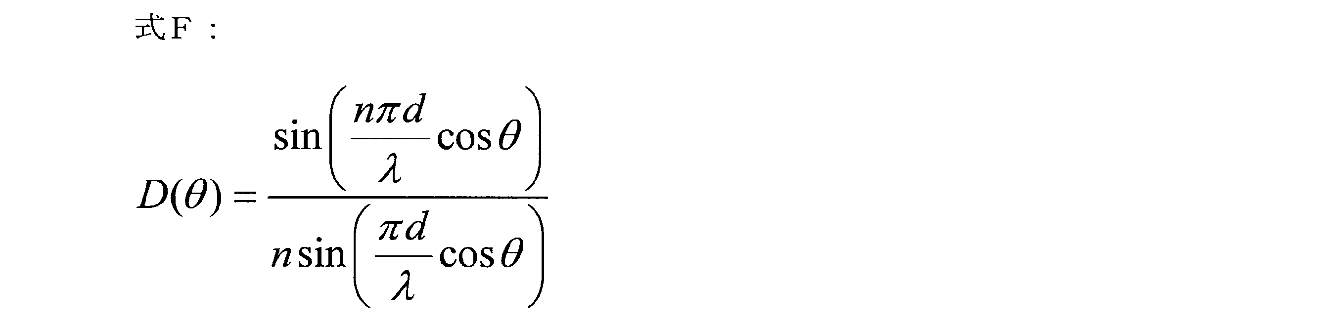
図17は、実施の形態4の送受信方法およびシステムとして、ビームフォーミングシステムの構成を示す。この構成は、実施の形態3の構成(図11)と異なる部分として、ビームの焦点(焦点エリア)3内において受信局2(ユーザ端末)側が複数となること、および、送信局1側の通信路NW41および通信路NW42を独立に機能させる自由度を持たせていること、がある。例えば、送信局1は、無線基地局等の送信装置であり、受信局2A,2Bは、ユーザ端末等の受信装置である。例えば受信局2Aを第1ユーザ端末、受信局2Bを第2ユーザ端末とする。これらの受信装置群は、ビームフォーミングによる焦点(焦点エリア)3の中で共存する。
図18を用いて、実施の形態4の送受信方法およびシステムを用いた具体的な利用例およびその効果等について説明する。図18には、実施の形態4の送受信方法およびシステムにおけるビームフォーミング機能の利用例として、ビームフォーミング時におけるマルチユーザ通信(言い換えるとマルチアクセス方式)の実現を示す。図18は、1つの基地局である送信局1のビームフォーミングの焦点エリア3に、4人のユーザ(加入者)の4台のユーザ端末である受信局2A,2B,2C,2Dが共存する場合を示している。さらに、この4人のユーザは、基幹通信事業者Aのユーザ以外に、複数のMVNO(仮想通信事業者)のユーザを含む場合を示す。そのMVNOは、この基地局(送信局1)を管理する基幹通信事業者Aからネットワークを借り受けてサービスをしているとする。本例では、受信局2Aは、基幹通信事業者AのユーザU1のユーザ端末であり、受信局2Bは、MVNO通信事業者BのユーザU2のユーザ端末であり、受信局2Cは、MVNO通信事業者CのユーザU3のユーザ端末であり、受信局2Dは、MVNO通信事業者DのユーザU4のユーザ端末である。送信局1の送信対象の複数のデータとして、例えばData#Aは基幹事業者Aのネットワーク461のユーザ端末2A宛先のデータであり、Data#BはMVNO事業者Bのネットワーク462からのユーザ端末2B宛先のデータであり、Data#CはMVNO事業者Cのネットワーク463のユーザ端末2C宛先のデータであり、Data#DはMVNO事業者Dのネットワーク464のユーザ端末2D宛先のデータである。
上記のように、実施の形態4によれば、ビームに複数の種類のデータを混在して伝送でき、マルチユーザ通信等の各種の応用が実現できる。実施の形態4によれば、ビームフォーミングの焦点面積の限界および多ユーザ環境への対応が可能となる。従来のビームフォーミングでは、焦点エリア3を小さくすることには限界があり、高密度にユーザが集まった環境で単独の受信局のみに焦点を結ぶことは難しい。それに対し、実施の形態4によれば、焦点エリア3内の複数の受信局2に対し同時にアクセスが可能となる。例えば、送信局1(伝搬路特性管理部404)は、焦点エリア3内に同時に居ると想定される受信局数に応じた複数のモデルを予め用意しておき、受信局2(伝搬路特性管理部409)毎にそれぞれの異なるモデルを設定する。これにより、上記のようなマルチアクセスが可能となる。
実施の形態3や実施の形態4の変形例として以下も可能である。前述の送信対象データは、必要な速度や信頼性等の観点で種類が異なるデータとして、少なくとも2種類のデータとして、第1データ(例えば第1送信データ群)と第2データ(例えば第2送信データ群)とを有する。送信局1および受信局2は、ビームを送受信する際の複数の疑似伝搬路の特性のうち、第1グループの複数の疑似伝搬路を、第1データを伝送するための第1通信回線に使用し、第2グループの別の複数の疑似伝搬路を、第2データを伝送するための第2通信回線に使用するように制御する。前述(図13等)のように、複数のモデルには、モデル間の相互相関性に高低の度合いがあり得る。この変形例では、複数の疑似伝搬路の特性(対応する複数のモデル)は、相互相関性の度合いに応じて、例えば、第1グループと、第1グループよりも相互相関性が高い第2グループとに分類される。送信局1および受信局2は、第1データが第2データよりも高信頼性を要求される種類のデータ(例えば制御プレーンデータ)である場合、第1データに第1グループを割り当て、第2データに第2グループを割り当てるように制御する。これにより、第1データの伝送は、第2データの伝送に比べてより高い信頼性が確保され得る。
実施の形態3および実施の形態4の変形例として、さらに以下も可能である。図19は、変形例の構成を示し、受信局2の図示を省略する。送信局1および受信局2は、上位制御によって、用途(例えば前述のCU分離やマルチアクセス通信等)に応じて、ビームフォーミング時の複数の通信回線を利用するように、切り替えや割り当て等の設定や制御を行うことができる。言い換えると、送信局1内および受信局2内には、各種の用途に利用できるように汎用的な構成の回路(前述の疑似伝搬路特性装置等)を含み、上位からの制御によって、用途に応じて、その回路に、前述の通信回線やモデルを設定することができる。上位制御は、例えば送信局1内の上位層、例えばCPU等のプロセッサ、またはベースバンド部内または外の専用回路による制御としてもよいし、送信局1の外部の他の基地局等の装置からの制御としてもよい。
図20は、各実施の形態に関する補足として、図1の疑似伝搬路特性装置101等における疑似伝搬路の実装例を示す。図20の疑似伝搬路は、FIR(Finite Impulse Response)フィルタで実装した構成例を示す。前述の図13のような疑似遅延プロファイルモデルの情報に基づいて、図20のようなフィルタ回路が構成可能である。図13では主波および遅延波の数は9であるが、ここでは説明のため、主波および遅延波2波の3波の場合で説明する。図20のFIRフィルタ回路において、入力D160は、第1乗算器1611において第1係数入力a1で乗算される。また、入力D160は、第1遅延器1601で所定の遅延が施されて、第1遅延信号D161となる。第1遅延信号D161は、第2乗算器1612で第2係数入力a2で乗算され、また、第2遅延器1602で遅延が施されて、第2遅延信号D162となる。第2遅延信号D162は、第3乗算器1613で第3係数入力a3で乗算される。すべての乗算器の出力は、加算器1620で加算され、出力D163となる。なお、FIRフィルタは、Z変換を用いて、H(z)=1+1/2z+1/4z2で表すことができる。H(z)は伝搬路特性関数である。zは、z=ejωTで表される。Tは単位遅延時間である。ωは角周波数である。上記のように、疑似伝搬路は、電子回路で実装でき、十分に高速な処理が可能である。
以上、本発明を実施の形態に基づいて具体的に説明したが、本発明は前述の実施の形態に限定されず、要旨を逸脱しない範囲で種々変更可能である。また以上の記述では、基地局側がSRS信号を送信し、端末側で実伝搬路特性を測定する例としたが、これは主にFDDの場合であって、TDDの場合には上り下りの周波数は同一のため、SRS信号を端末側で送信し基地局側で受信することも可能である。これにより、CSI(Channel State Information)の提供を不要とすることも可能である。また以上の記述では、ビームフォーミング機能のためのマルチアンテナを有する側が送信を行う形態としたが、マルチアンテナを有する側が受信を行う形態も同様に可能であり、前述の送受の形態を入れ替えることも可能である。
Claims (14)
- 複数の送信アンテナを持つ送信装置と、受信アンテナを持つ受信装置との間でデータを送受信する送受信方法であって、
前記送信装置または前記受信装置が、前記複数の送信アンテナと前記受信アンテナとの間の複数の実伝搬路の特性に基づいて、前記複数の実伝搬路の特性に対し周波数特性が近似できる程度に類似する特性である複数の疑似伝搬路の特性を生成する生成ステップと、
前記送信装置が、並列かつ独立の複数のデータに前記複数の疑似伝搬路の特性を反映して1つ以上の送信データを作成し、前記複数の送信アンテナから電波として送信する送信ステップと、
前記受信装置が、前記受信アンテナで電波として受信した1つ以上の受信データから、前記複数の疑似伝搬路の特性に基づいて、前記複数のデータを抽出する受信ステップと、
を有し、
前記送信装置は、MIMO送信機能を有し、
前記受信装置は、前記受信アンテナとして複数の受信アンテナを持ち、MIMO受信機能を有し、
前記生成ステップは、前記送信装置または前記受信装置が、前記複数の送信アンテナと前記複数の受信アンテナとの間の対角線上の伝搬路を含む複数の実伝搬路の特性に基づいて、前記複数の疑似伝搬路の特性を生成するステップであり、
前記対角線上の伝搬路は、前記複数の送信アンテナと前記複数の受信アンテナとの間で一対一で対向する伝搬路以外の伝搬路であり、
前記送信ステップは、前記送信装置が、前記複数のデータに前記複数の疑似伝搬路の特性を反映して並列かつ独立の複数の送信データを作成し、前記MIMO送信機能を用いて前記複数の送信アンテナから電波として送信するステップであり、
前記受信ステップは、前記受信装置が、前記複数の受信アンテナで電波として受信した信号から前記MIMO受信機能を用いて複数の受信データを作成し、前記複数の受信データから前記複数の疑似伝搬路の特性に基づいて前記複数のデータを抽出するステップである、
送受信方法。 - 請求項1記載の送受信方法において、
前記送信ステップは、前記送信装置が、前記MIMO送信機能を用いて作成した複数の送信データにおける2つの送信データから和信号および差信号を作成し、前記複数の送信アンテナにおける2つの送信アンテナから電波として送信するステップを含み、
前記和信号は、前記2つの送信データをSA1、SA2とした場合に、SA1+SA2という和をとった信号であり、前記差信号は、SA1-SA2という差をとった信号であり、
前記受信ステップは、前記受信装置が、前記複数の受信アンテナにおける2つの受信アンテナで電波として受信した信号から、前記MIMO受信機能を用いて複数の受信データにおける2つの受信データにおいて前記和信号および前記差信号を抽出するステップを含む、
送受信方法。 - 複数の送信アンテナを持つ送信装置と、1個以上の受信アンテナを持つ受信装置との間でデータを送受信する送受信方法であって、
前記送信装置は、前記複数の送信アンテナを含むビームフォーミング送信機能を有し、
前記受信装置は、前記受信アンテナを含むビームフォーミング受信機能を有し、
前記送信装置または前記受信装置が、前記複数の送信アンテナと前記受信アンテナとの間の複数の疑似伝搬路の特性を生成する生成ステップと、
前記送信装置が、種類が異なる複数のデータ群として少なくとも第1データ群と第2データ群とを含む、送信対象である並列かつ独立の複数のデータにおける各データを、前記複数の疑似伝搬路の特性における各特性に対応する疑似伝搬路に個別に載せた複数の出力から合成によって1つの送信データを作成する作成ステップと、
前記送信装置が、前記1つの送信データに基づいて前記ビームフォーミング送信機能によって前記複数の送信アンテナからビームを構成する電波群を送信する送信ステップと、
前記受信装置が、前記ビームの状態で到来した電波群から、前記受信アンテナを含む前記ビームフォーミング受信機能によって信号を受信する受信ステップと、
前記受信装置が、前記受信した信号から、前記複数の疑似伝搬路の特性の解析に基づいて、前記複数の疑似伝搬路の特性に載せられていた前記種類が異なる複数のデータ群を含む前記並列かつ独立の複数のデータに対応する複数のデータを抽出する抽出ステップと、
を有し、
前記種類が異なる複数のデータ群は、プロトコルスタック上の異なるプレーン、異なるベアラ、異なるチャネル、異なるスライス、異なる帯域制御サービス種別、または、緊急度の異なる通信におけるデータ群である、あるいは、制御・管理系の信号とアプリケーション系の信号とのデータ群である、
送受信方法。 - 複数の送信アンテナを持つ送信装置と、1個以上の受信アンテナを持つ複数の受信装置のそれぞれの受信装置との間でデータを送受信する送受信方法であって、
前記送信装置は、前記複数の送信アンテナを含むビームフォーミング送信機能を有し、
前記受信装置は、前記受信アンテナを含むビームフォーミング受信機能を有し、
前記送信装置からのビームの焦点エリアに前記複数の受信装置が含まれる場合に、
前記送信装置または前記複数の受信装置の1つが、前記複数の送信アンテナと前記受信アンテナとの間の複数の疑似伝搬路の特性を生成する生成ステップと、
前記送信装置が、種類が異なる複数のデータ群として少なくとも第1データ群と第2データ群とを含む、前記複数の受信装置に対する送信対象である並列かつ独立の複数のデータにおける各データを、前記複数の疑似伝搬路の特性における各特性に対応する疑似伝搬路に個別に載せた複数の出力から合成によって1つの送信データを作成する作成ステップと、
前記送信装置が、前記1つの送信データに基づいて前記ビームフォーミング送信機能によって前記複数の送信アンテナからビームを構成する電波群を送信する送信ステップと、
前記受信装置が、前記ビームの状態で到来した電波群から、前記受信アンテナを含む前記ビームフォーミング受信機能によって信号を受信する受信ステップと、
前記受信装置が、前記受信した信号から、前記複数の疑似伝搬路の特性のうちの自機に関する複数の疑似伝搬路の特性の解析に基づいて、前記自機に関する複数の疑似伝搬路の特性に載せられていた自機宛先のデータ群に対応する複数のデータを抽出する抽出ステップと、
を有する、送受信方法。 - 請求項1~4のいずれか1項に記載の送受信方法において、
前記複数の疑似伝搬路の特性は、前記複数の実伝搬路の特性における相互相関性よりも低い相互相関性を持つ、
送受信方法。 - 請求項1または2に記載の送受信方法において、
前記複数の疑似伝搬路の特性は、前記複数の実伝搬路の特性の測定結果を用いて、特徴部分をモデル化し、モデル間の相互相関性を低くする変形を施した特性である、
送受信方法。 - 請求項3または4に記載の送受信方法において、
前記生成ステップは、前記送信装置または前記受信装置が、予め設定された遅延プロファイルモデルに基づいて、前記複数の疑似伝搬路の特性を、前記複数の送信アンテナと前記1個以上の受信アンテナとの間の実伝搬路の特性とは独立に生成するステップである、
送受信方法。 - 請求項7に記載の送受信方法において、
前記生成ステップは、前記送信装置または前記受信装置が、前記複数の疑似伝搬路の前記遅延プロファイルとして、主波を軸に対称に配置し、前記主波と複数個の遅延波を、等しい時間間隔、または前記主波から時間軸上で関数を以て差を設けた時間間隔、または概ねランダムの時間間隔で配置し、前記主波と前記複数個の遅延波の各波の強度を複数の時間軸対称の関数の包絡線で管理した複数のモデルを生成するステップである、
送受信方法。 - 請求項1~8のいずれか1項に記載の送受信方法において、
前記複数の疑似伝搬路の特性に関する情報は、通信フレーム間のガード・インターバルの区間長に収容できる長さとする、
送受信方法。 - 請求項3または4に記載の送受信方法において、
前記複数の疑似伝搬路の特性は、相互相関性の度合いに応じて、第1グループと、前記第1グループよりも相互相関性が高い第2グループとに分類され、前記第1データ群が前記第2データ群よりも高信頼性を要求される種類のデータである場合、前記第1データ群に前記第1グループが割り当てられ、前記第2データ群に前記第2グループが割り当てられるように制御される、
送受信方法。 - 複数の送信アンテナを持つ送信装置と、受信アンテナを持つ受信装置との間でデータを送受信する送受信システムであって、
前記送信装置または前記受信装置は、前記複数の送信アンテナと前記受信アンテナとの間の複数の実伝搬路の特性に基づいて、前記複数の実伝搬路の特性に対し周波数特性が近似できる程度に類似する特性である複数の疑似伝搬路の特性を生成し、
前記送信装置は、並列かつ独立の複数のデータに前記複数の疑似伝搬路の特性を反映して1つ以上の送信データを作成し、前記複数の送信アンテナから電波として送信し、
前記受信装置は、前記受信アンテナで電波として受信した1つ以上の受信データから、前記複数の疑似伝搬路の特性に基づいて、前記複数のデータを抽出し、
前記送信装置は、MIMO送信機能を有し、
前記受信装置は、前記受信アンテナとして複数の受信アンテナを持ち、MIMO受信機能を有し、
前記送信装置または前記受信装置は、前記複数の送信アンテナと前記複数の受信アンテナとの間の対角線上の伝搬路を含む複数の実伝搬路の特性に基づいて、前記複数の疑似伝搬路の特性を生成し、
前記対角線上の伝搬路は、前記複数の送信アンテナと前記複数の受信アンテナとの間で一対一で対向する伝搬路以外の伝搬路であり、
前記送信装置は、前記複数のデータに前記複数の疑似伝搬路の特性を反映して並列かつ独立の複数の送信データを作成し、前記MIMO送信機能を用いて前記複数の送信アンテナから電波として送信し、
前記受信装置は、前記複数の受信アンテナで電波として受信した信号から前記MIMO受信機能を用いて複数の受信データを作成し、前記複数の受信データから前記複数の疑似伝搬路の特性に基づいて前記複数のデータを抽出する、
送受信システム。 - 請求項11記載の送受信システムにおいて、
前記送信装置は、前記MIMO送信機能を用いて作成した複数の送信データにおける2つの送信データから和信号および差信号を作成し、前記複数の送信アンテナにおける2つの送信アンテナから電波として送信し、
前記和信号は、前記2つの送信データをSA1、SA2とした場合に、SA1+SA2という和をとった信号であり、前記差信号は、SA1-SA2という差をとった信号であり、
前記受信装置は、前記複数の受信アンテナにおける2つの受信アンテナで電波として受信した信号から、前記MIMO受信機能を用いて複数の受信データにおける2つの受信データにおいて前記和信号および前記差信号を抽出する、
送受信システム。 - 複数の送信アンテナを持つ送信装置と、1個以上の受信アンテナを持つ受信装置との間でデータを送受信する送受信システムであって、
前記送信装置は、前記複数の送信アンテナを含むビームフォーミング送信機能を有し、
前記受信装置は、前記受信アンテナを含むビームフォーミング受信機能を有し、
前記送信装置または前記受信装置は、前記複数の送信アンテナと前記受信アンテナとの間の複数の疑似伝搬路の特性を生成し、
前記送信装置は、種類が異なる複数のデータ群として少なくとも第1データ群と第2データ群とを含む、送信対象である並列かつ独立の複数のデータにおける各データを、前記複数の疑似伝搬路の特性における各特性に対応する疑似伝搬路に個別に載せた複数の出力から合成によって1つの送信データを作成し、
前記送信装置は、前記1つの送信データに基づいて前記ビームフォーミング送信機能によって前記複数の送信アンテナからビームを構成する電波群を送信し、
前記受信装置は、前記ビームの状態で到来した電波群から、前記受信アンテナを含む前記ビームフォーミング受信機能によって信号を受信し、
前記受信装置は、前記受信した信号から、前記複数の疑似伝搬路の特性の解析に基づいて、前記複数の疑似伝搬路の特性に載せられていた前記種類が異なる複数のデータ群を含む前記並列かつ独立の複数のデータに対応する複数のデータを抽出し、
前記種類が異なる複数のデータ群は、プロトコルスタック上の異なるプレーン、異なるベアラ、異なるチャネル、異なるスライス、異なる帯域制御サービス種別、または、緊急度の異なる通信におけるデータ群である、あるいは、制御・管理系の信号とアプリケーション系の信号とのデータ群である、
送受信システム。 - 複数の送信アンテナを持つ送信装置と、1個以上の受信アンテナを持つ複数の受信装置のそれぞれの受信装置との間でデータを送受信する送受信システムであって、
前記送信装置は、前記複数の送信アンテナを含むビームフォーミング送信機能を有し、
前記受信装置は、前記受信アンテナを含むビームフォーミング受信機能を有し、
前記送信装置からのビームの焦点エリアに前記複数の受信装置が含まれる場合に、
前記送信装置または前記複数の受信装置の1つは、前記複数の送信アンテナと前記受信アンテナとの間の複数の疑似伝搬路の特性を生成し、
前記送信装置は、種類が異なる複数のデータ群として少なくとも第1データ群と第2データ群とを含む、前記複数の受信装置に対する送信対象である並列かつ独立の複数のデータにおける各データを、前記複数の疑似伝搬路の特性における各特性に対応する疑似伝搬路に個別に載せた複数の出力から合成によって1つの送信データを作成し、
前記送信装置は、前記1つの送信データに基づいて前記ビームフォーミング送信機能によって前記複数の送信アンテナからビームを構成する電波群を送信し、
前記受信装置は、前記ビームの状態で到来した電波群から、前記受信アンテナを含む前記ビームフォーミング受信機能によって信号を受信し、
前記受信装置は、前記受信した信号から、前記複数の疑似伝搬路の特性のうちの自機に関する複数の疑似伝搬路の特性の解析に基づいて、前記自機に関する複数の疑似伝搬路の特性に載せられていた自機宛先のデータ群に対応する複数のデータを抽出する、
送受信システム。
Priority Applications (5)
| Application Number | Priority Date | Filing Date | Title |
|---|---|---|---|
| CN202080045512.3A CN114521315A (zh) | 2019-06-21 | 2020-06-18 | 信号收发方法以及信号收发系统 |
| CA3144594A CA3144594C (en) | 2019-06-21 | 2020-06-18 | TRANSMISSION AND RECEPTION METHOD AND TRANSMISSION AND RECEPTION SYSTEM |
| KR1020227000965A KR102817717B1 (ko) | 2019-06-21 | 2020-06-18 | 송수신 방법 및 송수신 시스템 |
| US17/621,659 US11683074B2 (en) | 2019-06-21 | 2020-06-18 | Transmission/reception method and transmission/reception system |
| EP20826372.3A EP3989456A4 (en) | 2019-06-21 | 2020-06-18 | TRANSMITTING AND RECEIVING METHOD AS WELL AS TRANSMITTING AND RECEIVING SYSTEM |
Applications Claiming Priority (4)
| Application Number | Priority Date | Filing Date | Title |
|---|---|---|---|
| JP2019115472 | 2019-06-21 | ||
| JP2019-115472 | 2019-06-21 | ||
| JP2019-189558 | 2019-10-16 | ||
| JP2019189558A JP6723424B1 (ja) | 2019-06-21 | 2019-10-16 | 送受信方法および送受信システム |
Publications (1)
| Publication Number | Publication Date |
|---|---|
| WO2020256061A1 true WO2020256061A1 (ja) | 2020-12-24 |
Family
ID=71523914
Family Applications (1)
| Application Number | Title | Priority Date | Filing Date |
|---|---|---|---|
| PCT/JP2020/023937 Ceased WO2020256061A1 (ja) | 2019-06-21 | 2020-06-18 | 送受信方法および送受信システム |
Country Status (8)
| Country | Link |
|---|---|
| US (1) | US11683074B2 (ja) |
| EP (1) | EP3989456A4 (ja) |
| JP (1) | JP6723424B1 (ja) |
| KR (1) | KR102817717B1 (ja) |
| CN (1) | CN114521315A (ja) |
| CA (1) | CA3144594C (ja) |
| TW (1) | TWI821577B (ja) |
| WO (1) | WO2020256061A1 (ja) |
Families Citing this family (2)
| Publication number | Priority date | Publication date | Assignee | Title |
|---|---|---|---|---|
| EP4304234A4 (en) * | 2021-03-05 | 2024-11-20 | Ntt Docomo, Inc. | COMMUNICATION DEVICE AND COMMUNICATION METHOD |
| TWI833461B (zh) * | 2022-11-22 | 2024-02-21 | 緯創資通股份有限公司 | 規劃方法及其通訊裝置 |
Citations (7)
| Publication number | Priority date | Publication date | Assignee | Title |
|---|---|---|---|---|
| JPS57112150A (en) * | 1980-11-14 | 1982-07-13 | Western Electric Co | Fail safe system |
| JPH0998155A (ja) * | 1995-10-03 | 1997-04-08 | Matsushita Electric Ind Co Ltd | 光送信装置およびそれを用いた光伝送システム |
| US20040136341A1 (en) * | 2002-12-26 | 2004-07-15 | Motorola, Inc. | Antenna method and apparatus |
| JP2009225147A (ja) * | 2008-03-17 | 2009-10-01 | Fujitsu Ltd | 無線通信システム及び無線通信方法並びに送信装置及び受信装置 |
| JP2016027686A (ja) * | 2014-07-01 | 2016-02-18 | 日本電信電話株式会社 | 光伝送システム及び信号伝送方法 |
| JP2018118353A (ja) | 2017-01-26 | 2018-08-02 | ファナック株式会社 | 学習制御機能を備えた制御システム及び制御方法 |
| JP6497472B1 (ja) | 2018-06-21 | 2019-04-10 | 株式会社横須賀テレコムリサーチパーク | 送受信方法、および送受信システム |
Family Cites Families (17)
| Publication number | Priority date | Publication date | Assignee | Title |
|---|---|---|---|---|
| JP2003249918A (ja) * | 2002-02-25 | 2003-09-05 | Matsushita Electric Ind Co Ltd | 受信装置および受信方法 |
| US7095709B2 (en) | 2002-06-24 | 2006-08-22 | Qualcomm, Incorporated | Diversity transmission modes for MIMO OFDM communication systems |
| EP1724957A1 (en) * | 2004-03-11 | 2006-11-22 | Matsushita Electric Industrial Co., Ltd. | Data transmission method and data reception method |
| EA018436B1 (ru) * | 2005-10-31 | 2013-08-30 | Шарп Кабусики Кайся | Беспроводное передающее устройство |
| TWI357234B (en) | 2005-11-02 | 2012-01-21 | Qualcomm Inc | Antenna array calibration for multi-input multi-ou |
| JP2009272725A (ja) * | 2008-04-30 | 2009-11-19 | Sharp Corp | 通信システム、受信装置及び通信方法 |
| JP2010021922A (ja) * | 2008-07-14 | 2010-01-28 | Tokyo Univ Of Science | 無線通信システム、受信装置及び無線通信方法 |
| JP5177527B2 (ja) * | 2008-07-28 | 2013-04-03 | シャープ株式会社 | 通信システム、受信装置及び通信方法 |
| KR101241916B1 (ko) | 2010-02-07 | 2013-03-11 | 엘지전자 주식회사 | 다중 안테나를 지원하는 무선 통신 시스템에서 하향링크 참조신호를 전송하는 방법 및 장치 |
| CN102857325B (zh) | 2011-06-27 | 2017-08-04 | 华为技术有限公司 | 确定控制信道资源的方法和用户设备 |
| US9882614B2 (en) * | 2012-02-06 | 2018-01-30 | Nippon Telegraph And Telephone Corporation | Wireless signal transmitting method and wireless apparatus |
| JP5650706B2 (ja) * | 2012-11-07 | 2015-01-07 | アンリツ株式会社 | Mimo方式システムの試験装置および試験方法 |
| KR102177804B1 (ko) * | 2014-03-25 | 2020-11-11 | 삼성전자주식회사 | 다중입력 다중출력 시스템에서 스케줄링 방법 및 장치 |
| EP2991241A1 (en) | 2014-08-27 | 2016-03-02 | Fraunhofer-Gesellschaft zur Förderung der angewandten Forschung e.V. | Sudac, user equipment, base station and sudac system |
| JP6074449B2 (ja) * | 2015-03-20 | 2017-02-01 | アンリツ株式会社 | Mimoシステム試験装置およびそのチャネル相関情報設定方法 |
| WO2018231141A1 (en) | 2017-06-16 | 2018-12-20 | Telefonaktiebolaget Lm Ericsson (Publ) | Multi-resource uplink sounding and antenna subset transmission |
| CN111224696B (zh) * | 2018-11-26 | 2021-04-20 | 深圳市通用测试系统有限公司 | 无线终端的无线性能测试方法及系统 |
-
2019
- 2019-10-16 JP JP2019189558A patent/JP6723424B1/ja active Active
-
2020
- 2020-06-18 CA CA3144594A patent/CA3144594C/en active Active
- 2020-06-18 KR KR1020227000965A patent/KR102817717B1/ko active Active
- 2020-06-18 WO PCT/JP2020/023937 patent/WO2020256061A1/ja not_active Ceased
- 2020-06-18 EP EP20826372.3A patent/EP3989456A4/en not_active Withdrawn
- 2020-06-18 CN CN202080045512.3A patent/CN114521315A/zh active Pending
- 2020-06-18 US US17/621,659 patent/US11683074B2/en active Active
- 2020-06-20 TW TW109120985A patent/TWI821577B/zh active
Patent Citations (7)
| Publication number | Priority date | Publication date | Assignee | Title |
|---|---|---|---|---|
| JPS57112150A (en) * | 1980-11-14 | 1982-07-13 | Western Electric Co | Fail safe system |
| JPH0998155A (ja) * | 1995-10-03 | 1997-04-08 | Matsushita Electric Ind Co Ltd | 光送信装置およびそれを用いた光伝送システム |
| US20040136341A1 (en) * | 2002-12-26 | 2004-07-15 | Motorola, Inc. | Antenna method and apparatus |
| JP2009225147A (ja) * | 2008-03-17 | 2009-10-01 | Fujitsu Ltd | 無線通信システム及び無線通信方法並びに送信装置及び受信装置 |
| JP2016027686A (ja) * | 2014-07-01 | 2016-02-18 | 日本電信電話株式会社 | 光伝送システム及び信号伝送方法 |
| JP2018118353A (ja) | 2017-01-26 | 2018-08-02 | ファナック株式会社 | 学習制御機能を備えた制御システム及び制御方法 |
| JP6497472B1 (ja) | 2018-06-21 | 2019-04-10 | 株式会社横須賀テレコムリサーチパーク | 送受信方法、および送受信システム |
Non-Patent Citations (9)
Also Published As
| Publication number | Publication date |
|---|---|
| JP2021002822A (ja) | 2021-01-07 |
| EP3989456A1 (en) | 2022-04-27 |
| US20220360299A1 (en) | 2022-11-10 |
| TW202101924A (zh) | 2021-01-01 |
| TWI821577B (zh) | 2023-11-11 |
| CA3144594C (en) | 2024-10-15 |
| EP3989456A4 (en) | 2023-09-13 |
| CA3144594A1 (en) | 2020-12-24 |
| KR20220018057A (ko) | 2022-02-14 |
| US11683074B2 (en) | 2023-06-20 |
| CN114521315A (zh) | 2022-05-20 |
| JP6723424B1 (ja) | 2020-07-15 |
| KR102817717B1 (ko) | 2025-06-09 |
Similar Documents
| Publication | Publication Date | Title |
|---|---|---|
| Parvez et al. | A survey on low latency towards 5G: RAN, core network and caching solutions | |
| US12218782B2 (en) | Techniques for communicating beam information | |
| Dötsch et al. | Quantitative analysis of split base station processing and determination of advantageous architectures for LTE | |
| CN102362448B (zh) | 用于中继多输入多输出信号的单输入单输出中继器 | |
| Aijaz et al. | Toward a tactile Internet reference architecture: Vision and progress of the IEEE P1918. 1 standard | |
| WO2016018968A1 (en) | Scaling wireless full duplex in multi-cell networks with spatial interference alignment | |
| US20230299898A1 (en) | Method and device in nodes used for wireless communication | |
| US12224860B1 (en) | Linear coding in decentralized networks | |
| JP6723424B1 (ja) | 送受信方法および送受信システム | |
| Meng et al. | Cooperative user-scheduling and resource allocation optimization for intelligent reflecting surface enhanced LEO satellite communication | |
| Vaigandla et al. | Analysis of PAPR and Beamforming for 5G MIMO-OFDM | |
| JP5417590B2 (ja) | 無線装置およびそれを備えた無線通信システム | |
| Pan et al. | Prospects of 6G Technology Framework: A Big-Lite Multi-RATs Concept | |
| Xu et al. | Cognitive backscatter communication: Symbiotic radio systems assisted by reconfigurable intelligent surface | |
| Bhatia et al. | Non-orthogonal multiple access as an enabler for massive connectivity for 5G and beyond networks | |
| RU2786185C1 (ru) | Способ передачи/приёма и система передачи/приёма | |
| KR20240047236A (ko) | 무선 통신 시스템에서 신호를 처리하는 방법 및 장치 | |
| Tran et al. | Effective capacity analysis of configurable intelligent surface-assisted NOMA communications systems | |
| Fitzek et al. | Intelligent networks | |
| Hung et al. | On the block error rate performance of cooperative non‐orthogonal multiple access short‐packet communications with full‐duplex relay and partial relay selection | |
| Torkzaban | Design and optimization of 5g and beyond hybrid communication systems | |
| US20250337463A1 (en) | Wireless links for data center traffic | |
| Aroca García | Implementation of interference coordination techniques within a dynamic functional split adaptation | |
| OA et al. | Performance Evaluatıon of Beamformıng in 5G OFDM Systems and Advantages over 4G. | |
| Kim et al. | Performance analysis of simultaneous collision-free duplexing method in point-to-multipoint environment |
Legal Events
| Date | Code | Title | Description |
|---|---|---|---|
| 121 | Ep: the epo has been informed by wipo that ep was designated in this application |
Ref document number: 20826372 Country of ref document: EP Kind code of ref document: A1 |
|
| ENP | Entry into the national phase |
Ref document number: 3144594 Country of ref document: CA |
|
| NENP | Non-entry into the national phase |
Ref country code: DE |
|
| ENP | Entry into the national phase |
Ref document number: 20227000965 Country of ref document: KR Kind code of ref document: A |
|
| WWE | Wipo information: entry into national phase |
Ref document number: 202237003222 Country of ref document: IN |
|
| WWE | Wipo information: entry into national phase |
Ref document number: 2021138474 Country of ref document: RU Ref document number: 2020826372 Country of ref document: EP |
|
| WWG | Wipo information: grant in national office |
Ref document number: 202237003222 Country of ref document: IN |