WO2020261637A1 - 列車制御装置、方法及びプログラム - Google Patents
列車制御装置、方法及びプログラム Download PDFInfo
- Publication number
- WO2020261637A1 WO2020261637A1 PCT/JP2020/006587 JP2020006587W WO2020261637A1 WO 2020261637 A1 WO2020261637 A1 WO 2020261637A1 JP 2020006587 W JP2020006587 W JP 2020006587W WO 2020261637 A1 WO2020261637 A1 WO 2020261637A1
- Authority
- WO
- WIPO (PCT)
- Prior art keywords
- train
- control
- block section
- control logic
- state
- Prior art date
- Legal status (The legal status is an assumption and is not a legal conclusion. Google has not performed a legal analysis and makes no representation as to the accuracy of the status listed.)
- Ceased
Links
Images







Classifications
-
- B—PERFORMING OPERATIONS; TRANSPORTING
- B61—RAILWAYS
- B61L—GUIDING RAILWAY TRAFFIC; ENSURING THE SAFETY OF RAILWAY TRAFFIC
- B61L27/00—Central railway traffic control systems; Trackside control; Communication systems specially adapted therefor
- B61L27/40—Handling position reports or trackside vehicle data
-
- B—PERFORMING OPERATIONS; TRANSPORTING
- B61—RAILWAYS
- B61L—GUIDING RAILWAY TRAFFIC; ENSURING THE SAFETY OF RAILWAY TRAFFIC
- B61L15/00—Indicators provided on the vehicle or train for signalling purposes
- B61L15/0018—Communication with or on the vehicle or train
- B61L15/0027—Radio-based, e.g. using GSM-R
-
- B—PERFORMING OPERATIONS; TRANSPORTING
- B61—RAILWAYS
- B61L—GUIDING RAILWAY TRAFFIC; ENSURING THE SAFETY OF RAILWAY TRAFFIC
- B61L19/00—Arrangements for interlocking between points and signals by means of a single interlocking device, e.g. central control
- B61L19/06—Interlocking devices having electrical operation
-
- B—PERFORMING OPERATIONS; TRANSPORTING
- B61—RAILWAYS
- B61L—GUIDING RAILWAY TRAFFIC; ENSURING THE SAFETY OF RAILWAY TRAFFIC
- B61L21/00—Station blocking between signal boxes in one yard
- B61L21/04—Electrical locking and release of the route; Electrical repeat locks
-
- B—PERFORMING OPERATIONS; TRANSPORTING
- B61—RAILWAYS
- B61L—GUIDING RAILWAY TRAFFIC; ENSURING THE SAFETY OF RAILWAY TRAFFIC
- B61L27/00—Central railway traffic control systems; Trackside control; Communication systems specially adapted therefor
- B61L27/20—Trackside control of safe travel of vehicle or train, e.g. braking curve calculation
-
- B—PERFORMING OPERATIONS; TRANSPORTING
- B61—RAILWAYS
- B61L—GUIDING RAILWAY TRAFFIC; ENSURING THE SAFETY OF RAILWAY TRAFFIC
- B61L27/00—Central railway traffic control systems; Trackside control; Communication systems specially adapted therefor
- B61L27/20—Trackside control of safe travel of vehicle or train, e.g. braking curve calculation
- B61L2027/204—Trackside control of safe travel of vehicle or train, e.g. braking curve calculation using Communication-based Train Control [CBTC]
-
- B—PERFORMING OPERATIONS; TRANSPORTING
- B61—RAILWAYS
- B61L—GUIDING RAILWAY TRAFFIC; ENSURING THE SAFETY OF RAILWAY TRAFFIC
- B61L2201/00—Control methods
Definitions
- the present invention relates to train control devices, methods and programs.
- the present application claims priority with respect to Japanese Patent Application No. 2019-118980 filed in Japan on June 26, 2019, the contents of which are incorporated herein by reference.
- the train operation control device described in Patent Document 1 generates a control command for a traffic light installed at a start point of each block section of a railway line connected via a network, and generates a control command for each traffic light. Send.
- the train operation control device described in Patent Document 1 includes a state information recording unit, a signal control unit, a control command recording unit, and an input / output control unit.
- the status information recording unit acquires the status information of the traffic light, the current position information of the train obtained from the train position information source, and the status information of the equipment provided in the specific block section of the railway line via the network, and logs it. Record in a file.
- the signal control unit acquires the latest traffic light status information, train current position information, and equipment status information from the log file, and creates a control command for the traffic light.
- the control command recording unit records the created control command and the manually operated control command transmitted from the terminal in the log fill.
- the input / output control unit transmits the control command created by the signal control unit to the traffic signal via the network. Then, the signal control unit has to collectively control the block section where the train is going to travel, which is located next to the block section where the train exists, based on the operation schedule of the train.
- operation control is performed based on the result of determining whether or not a plurality of blocked sections can be passed.
- the calculation cost increases, for example, the calculation time becomes long. That is, for example, when there are a plurality of combinations of control states that can be passed, if the optimum solution such as the combination of control states that has the shortest passage time is to be obtained, the calculation time becomes long. There is a problem that the cost increases.
- the present invention provides a train control device, a method and a program capable of suppressing an increase in calculation cost related to train control.
- One aspect of the present invention is defined by the number and connection modes of a plurality of block sections constituting a track included in a predetermined controlled area and the number of trains existing on the track, and is the train to be controlled1.
- a train control device that controls a train by using an environment model in which the state changes discretely depending on the combination of the position of the train to be controlled, the position of other trains of 0 or more, and the presence or absence of reservation of each block section.
- the control logic generation unit that generates the control logic that is the logic for transitioning the state, and the controlled train according to the state of the environment model based on the generated control logic until the predetermined condition is satisfied.
- An action determination unit that sequentially determines an action, and a reproduction instructing the control logic generation unit to regenerate the control logic with the state of the environment model at that time as the initial state before the predetermined condition is satisfied. It is a train control device provided with an instruction unit.
- one aspect of the present invention is the train control device, and the predetermined condition includes a condition to be reached as a target state and a condition not to be reached.
- one aspect of the present invention is the train control device, wherein the control logic includes a flow of state transitions of each block section included in the control target area and each of the actions sequentially performed by the control target train. Includes information indicating the association of.
- one aspect of the present invention is the train control device, and the regeneration instruction unit of the control logic with respect to the control logic generation unit each time the state of the environment model changes a plurality of times. Instruct regeneration.
- one aspect of the present invention is the train control device, wherein the regeneration instruction unit uses the environment model changed with respect to the control logic generation unit when the environment model changes. Instructs the regeneration of control logic.
- one aspect of the present invention is the train control device, in which the control logic generation unit generates the control logic for each partial control region which is a region obtained by dividing the control target region into a plurality of regions.
- the control logic generation unit is instructed to regenerate the control logic.
- one aspect of the present invention is the control logic in the train control device when the controlled train approaches a partial control area different from the partial control area in which the controlled train exists.
- the generation unit is further provided with an additional generation instruction unit that instructs the generation unit to generate the control logic for the other partial control area in addition to the generation of the control logic for the partial control area in which the train to be controlled exists. ..
- one aspect of the present invention is the train control device, further comprising an area redefinition unit that redefines the partial control area according to the position of the train to be controlled.
- one aspect of the present invention is the train control device, which is mounted on the train.
- one aspect of the present invention is defined by the number and connection modes of a plurality of block sections constituting the track included in the predetermined controlled area and the number of trains existing on the track, and the train to be controlled.
- the environment depending on the step of selecting one of the actions of "moving to the reserved section” or “waiting in the blocked section currently located” and the result of the selection.
- the step of generating the control logic which is the logic for changing the state of the model, and the action performed by the controlled train according to the state of the environment model based on the generated control logic until the predetermined condition is satisfied.
- This is a method of controlling a train including a step of sequentially determining the above-mentioned trains and a step of regenerating the control logic with the state of the environment model at that time as the initial state before the predetermined condition is satisfied.
- one aspect of the present invention is defined by the number and connection modes of a plurality of block sections constituting the track included in the predetermined controlled area and the number of trains existing on the track, and the train to be controlled.
- the environment depending on the step of selecting one of the actions of "moving to the reserved section” or “waiting in the blocked section currently located” and the result of the selection.
- the step of generating the control logic which is the logic for changing the state of the model, and the action performed by the controlled train according to the state of the environment model based on the generated control logic until the predetermined condition is satisfied.
- a step of sequentially determining the steps and a step of regenerating the control logic with the state of the environment model at that time as the initial state before the predetermined condition is satisfied are performed on the computer constituting the device for controlling the train. It is a program to be executed.
- control logic since the control logic can be updated during train operation, it can be generated without increasing the calculation cost as compared with the case where the efficient control logic is not updated.
- FIG. 5 is a block diagram showing another configuration example (fifth embodiment) of the train control device 1 and the on-board device 2 shown in FIG.
- FIG. 5 is a block diagram showing another configuration example (fifth embodiment) of the train control device 1 and the on-board device 2 shown in FIG.
- FIG. 5 is a block diagram showing another configuration example (fifth embodiment) of the train control device 1 and the on-board device 2 shown in FIG.
- FIG. 5 is a block diagram showing another configuration example (fifth embodiment) of the train control device 1 and the on-board device 2 shown in FIG.
- FIG. 5 is a block diagram showing another configuration example (fifth embodiment) of the train control device 1 and the on-board device 2 shown in FIG.
- FIG. 5 is a block diagram showing another configuration example (fifth embodiment) of the train control device 1 and the on-board device 2 shown in FIG.
- FIG. 1 It is a schematic diagram for demonstrating the operation example (sixth embodiment) of the train control apparatus 1b shown in FIG. It is a schematic block diagram which shows the structure of the computer which concerns on at least one Embodiment. It is a schematic diagram used for the explanation of the train control device 1 shown in FIG. It is a schematic diagram used for the explanation of the train control device 1 shown in FIG. It is a schematic diagram used for the explanation of the train control device 1 shown in FIG. It is a schematic diagram used for the explanation of the train control device 1 shown in FIG.
- FIG. 1 is a configuration diagram showing a configuration example of the train control device 1 according to the embodiment of the present invention.
- the track system 3 includes a train control device 1, a track (also referred to as a “track line”) 4, and one or more trains T1, T2, and the like.
- the orbit 4 is composed of a plurality of block sections (“block sections” are also referred to as “blocks” (blocks) and are described) B1, B2, B3, B4, B5 and the like.
- Each train T1 and T2 is composed of one or a plurality of vehicles traveling on the track 4.
- Each train T1 and T2 includes an on-board device 2.
- the block section is a section where only one train is allowed to enter. Further, when entering a certain block section, the block section can be reserved prior to the approach, and if the reservation can be made, the block section can be entered. Only one train is allowed to reserve each block section.
- the train control device 1 includes a central control device 11 and a computer 12.
- the central control device 11 is composed of one or a plurality of computers and peripheral devices thereof, and remotely controls each train T1 and T2 by logical control (discrete control) based on the position information of each train T1 and T2.
- the central control device 11 receives the position information of each train T1 and T2 transmitted by each on-board device 2, and each train T1 and T2 according to the control logic generated in advance based on the received position information of each train T1 and T2.
- a control command is sent to each train T1 and T2 to be logically controlled.
- the control logic is a logic control program (details will be described later).
- the computer 12 calculates and generates the control logic.
- the train control device 1 sets a predetermined area on the track 4 as the control target area C11, and generates control logic for each specific control target train (control target train) located in the control target area C11. ..
- the controlled area C11 includes the closed sections B1, B2, B3, B4 and B5.
- the block section B3 is a portion where one line branches into two lines, and is regarded as one block section including the branched part.
- the arrow in the broken line block indicating the block section indicates the direction in which the train in the block section will proceed next.
- the block section B1 is connected to the block section B2, the block section B2 is connected to the block section B3, and the block section B3 is connected to the block section B4 and the block section B5 via a branch portion. Further, the train T2 is located in the block section B1, and the train T1 is located in the block section B5. Further, from the block section B1, movement in the block section B2 direction indicated by a white arrow is permitted. From the block section B2, movement in the direction of the block section B3 indicated by the black arrow is permitted. From the block section B3, the train entering from the block section B2 is allowed to move in the block section B4 direction, and the train entering from the block section B5 is allowed to move in the block section B2 direction. .. From the block section B5, movement in the direction of the block section B3 indicated by the white arrow is permitted. The white arrow indicates the state in which the block section is reserved, and the black arrow indicates the state in which the reservation of the block section is canceled.
- the control logic includes a track 4 divided into a plurality of block sections B1 to B5, and one controlled target train existing on the track 4 (hereinafter, the train T1 is referred to as a controlled target train T1).
- the train T1 is referred to as a controlled target train T1
- train T2 is referred to as other train T2
- the action of the train T1 to be controlled can be selected from "Reservation / cancellation of block section", "Move to reserved block section", and "Waiting in the current block section". The logic to decide.
- the environment model is a model representing the environment to be controlled, and the number (5 in this case) of the plurality of closed sections B1 to B5 constituting the orbit 4 included in the predetermined controlled area C11 and the connection form (in this case, 5). It is defined by the relationship between the connection of each block section B1 to B5 and the traveling direction) and the number of trains existing on the track 4 (two in this case). Then, in the environmental model, the position of the controlled train T1 of 1 which is the train to be controlled (in this case, the blocked section B5), the position of another train T2 of 0 or more (in this case, the blocked section B1), and the reservation of each blocked section. The state changes discretely depending on the combination of the presence or absence of.
- the train T1 to be controlled may be referred to as a own train (relative to another train T2).
- the information indicating the number of block sections forming the track and the connection form may be referred to as track route information.
- control logic needs to satisfy the Safety condition (safety condition) and the goal condition.
- the Safety conditions are, for example, "no matter what kind of movement other trains make, no dangerous result such as collision will occur”, “no matter what control the controlled train controls, it will fall into a deadlock”. It is a condition that must not be reached under any circumstances, such as "No".
- the goal condition is a condition that must be reached as a target state such as "arriving at a designated station after leaving the garage” or "reaching a specific block section in the controlled area".
- the goal condition may be composed of a combination of a plurality of target states such as "after satisfying a certain intermediate state, the other final state is reached”.
- the control logic targeted by the present embodiment aims to "achieve the goal condition without falling into a deadlock". That is, in the present embodiment, the control logic is generated so as to satisfy a predetermined condition which is a condition for passing through the controlled target area.
- the predetermined condition includes a condition to be reached as a target state of "achieving the goal condition” and a condition not to be reached "without falling into a deadlock".
- the control logic includes information indicating the correspondence between the flow of the state transition of each block section included in the controlled area and each action sequentially performed by the controlled train.
- the control logic presents the actions taken by the train to be controlled according to the state of the environmental model.
- a control logic may be generated that presents a plurality of actions (actions that can reach the goal condition) that the controlled train may take to achieve the goal condition. In actual operation, only one action is selected and executed from the presented multiple actions in some way.
- the "environmental model” and “control logic” in this embodiment can be summarized as follows. That is, in the present embodiment, the “environmental model” is defined by (1) the number of block sections forming the track, the connection form (connection shape), and (2) the number of trains existing on the track. Then, the “environmental model” takes a discrete state based on a combination of the position of the train to be controlled, the position of other trains, and the presence or absence of reservation of each block section (whether the reservation of own train or the reservation of another train). (State transitions discretely).
- the state of the "environmental model” is defined for each train. For example, when there are three trains (trains (A), (B), (C)), the state of the environmental model used to control the train (A) is (a) the position of the train to be controlled (train A).
- control logic refers to "reservation / cancellation of block section", “movement to the reserved block section”, and “movement to the reserved block section” for the train to be controlled, depending on the state of the "environment model”. This is the logic that determines one of the actions of "waiting in the current block section” and makes the “environment model” state transition. Further, the “control logic” is generated so that (1) the train to be controlled reaches the target block section from the current block section, and (2) deadlock does not occur.
- the "control logic" in the present embodiment can be automatically generated by using MTSA (Modal Transition System Analyzer), which is a tool released as open source.
- MTSA is, has been jointly developed by Imperial College London (Distributed Software Engineering (DSE) group at Imperial College London) and the University of wholesome Aires (the Laboratory on Foundations and Tools for Software Engineering (LaFHIS) at University of wholesome Aires) , An automatic generation tool that takes a formally described environment model and requirements as input, and automatically generates a specification model (state of the environment model) whose correctness is guaranteed based on the game theory (URL: http: http: // mtsa.dc.uba.ar).
- the present invention is not limited to this, and the "control logic" may be generated by using a program that combines processes for performing a plurality of condition determinations, for example, as described in Patent Document 1.
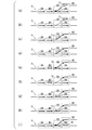
- FIGS. 16 to 18 are schematic views used for explaining the train control device 1 shown in FIG.
- 16 (a) to 16 (i) are for achieving the goal condition that "the train T1 in the block section B5 moves to the block section B4" when only the train T1 to be controlled exists on the track 4.
- the control procedure with the minimum number of state transitions is shown.
- the block section including the white arrow is a block section reserved for entry, and only the train that made the reservation can enter the block section. Further, in this example, in order to move from the block section B3 including the branch to the block section B4 on the right side, after entering the block section B2, the direction is changed and the block section B3 is entered again, and then the block section B4 is entered. There is a need to.
- FIG. 16A shows a state in which the control target train T1 is located in the block section B5 and the block section B5 is reserved for the control target train T1.
- FIG. 16B shows a state in which the control target train T1 is located in the block section B5, and the block section B5 and the block section B3 are reserved for the control target train T1.
- FIG. 16C shows a state in which the control target train T1 moves to the block section B3, the block section B3 is reserved for the control target train T1, and the block section B5 is canceled.
- FIG. 16D shows a state in which the control target train T1 is located in the block section B3, and the block section B3 and the block section B2 are reserved for the control target train T1.
- FIG. 16 (e) shows a state in which the control target train T1 moves to the block section B2, the block section B2 is reserved for the control target train T1, and the block section B3 is canceled.
- FIG. 16F shows a state in which the control target train T1 is located in the block section B2, and the block section B2 and the block section B3 are reserved for the control target train T1.
- FIG. 16 (g) shows a state in which the control target train T1 moves to the block section B3, the block section B3 is reserved for the control target train T1, and the block section B2 is canceled.
- FIG. 16H shows a state in which the control target train T1 is located in the block section B3, and the block section B3 and the block section B4 are reserved for the control target train T1.
- FIG. 16 (i) shows a state in which the control target train T1 moves to the block section B4, the block section B4 is reserved for the control target train T1, and the block section B3 is canceled.
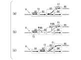
- FIG. 17 show, as a reference example, a state in which a train T1 to be controlled and one other train T2 are present on the track 4 and both of them are stuck in a deadlock forever. .. In this case, the deadlock occurred because the two trains T1 and T2 each reserved the block sections facing each other. However, in this embodiment, such control logic is not created.
- the control target train T1 is located in the block section B5, the other train T2 is located in the block section B1, the block section B5 is reserved for the control target train T1, and the block section B1 is another.
- the control target train T1 is located in the block section B5, the block section B5 and the block section B3 are reserved for the control target train T1, and the other train T2 is located in the block section B1 and is blocked.
- the control target train T1 moves to the block section B3, the block section B3 is reserved for the control target train T1, the reservation for the block section B5 is canceled, and the other train T2 is reserved for the block section B2.
- FIGS. 18 show an example in which the train T1 to be controlled and one other train T2 are present on the track 4 and the goal condition is reached without deadlock. Deadlock is avoided by reserving a block section where the controlled train T1 crosses the branch to another block ahead.
- the number of cars that make up one train set is one or more and there is no upper limit, but the length of the train shall be shorter than the length of the shortest block section.
- the control target train T1 is located in the block section B5, the other train T2 is located in the block section B1, the block section B5 is reserved for the control target train T1, and the block section B1 is another.
- the control target train T1 is located in the block section B5, the other train T2 is located in the block section B1, and the block section B5 and the block section B2 are reserved for the control target train T1 and are blocked.
- the control target train T1 is located in the block section B5, the other train T2 is located in the block section B1, and the block section B5, the block section B2, and the block section B3 are relative to the control target train T1.
- the controlled train T1 moves to the block section B3, the other train T2 is located in the block section B1, and the block section B2 and the block section B3 are reserved for the block section T1 and are blocked.
- Indicates a state in which the section B1 is reserved for the other train T2 and the block section B5 is canceled.
- the control target train T1 moves to the block section B2, the other train T2 is located in the block section B1, the block section B2 is reserved for the control target train T1, and the block section B1 is another. Indicates a state in which the reservation is made for the train T2 and the reservation for the block section B3 is canceled.
- the control target train T1 is located in the block section B2
- the other train T2 is located in the block section B1
- the block section B2 and the block section B3 are reserved for the control target train T1 and are blocked.
- the control target train T1 moves to the block section B3, the other train T2 is located in the block section B1, the block section B3 is reserved for the control target train T1, and the block section B1 is another. Indicates a state in which the reservation is made for the train T2 and the reservation for the block section B2 is canceled.
- the control target train T1 is located in the block section B3, the other train T2 is located in the block section B1, and the block section B3 and the block section B4 are reserved for the control target train T1 and are blocked.
- the control target train T1 moves to the block section B4, the other train T2 is located in the block section B1, the block section B4 is reserved for the control target train T1, and the block section B1 is another. Indicates a state in which the reservation is made for the train T2 and the reservation for the block section B3 is canceled.
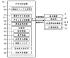
- FIG. 2 is a block diagram showing a configuration example of the train control device 1 and the on-board device 2 shown in FIG.
- the computer 12 has a control logic generation unit 50.
- the central control device 11 has an environment model generation unit 51, an action determination unit 52, a regeneration instruction unit 53, and a storage unit 54.
- the control logic generation unit 50, the environment model generation unit 51, the action determination unit 52, the regeneration instruction unit 53, and the storage unit 54 are one or a plurality of computers constituting the computer 12 and the central control device 11. It is a functional component composed of a combination of hardware such as peripheral devices of the computer and software such as programs executed by the computer.
- the storage unit 54 stores the setting information 55, the condition information 56, the position reservation information 57, and the control logic 58.
- the setting information 55 includes various information used when generating an environment model.
- the various information includes, for example, the number of the plurality of block sections B1 to B5 and the like constituting the track 4 included in the controlled target area C11 and the like, the connection form (referred to as track route information), and the train T1 existing on the track 4.
- Information on the number of trains such as T2 (referred to as train number information).
- the condition information 56 includes information indicating a Safety condition and a goal condition for each train.
- the position reservation information 57 includes information indicating the presence / absence of trains and, if so, which train exists (referred to as train position information), and information indicating the presence / absence of reservation (referred to as block reservation information) for each block section. ) Etc., including information used as an initial value when generating control logic, history changed by train control, information representing the latest state, and the like.
- the control logic 58 includes information representing the control logic for each train generated by the control logic generation unit 50.
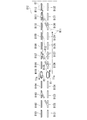
- FIG. 3 is a schematic diagram showing a configuration example of the control logic 58 shown in FIG.
- FIG. 3 shows an example of the control logic 58 shown in the form of a state transition table.
- the control logic 58 shown in FIG. 3 is a logic for transitioning the state of the environment model corresponding to the orbit 4 included in the controlled target area C11 shown in FIG. 1, and is composed of state numbers 1, 2, 3, 4, 5, ...
- the controlled train T1 (in FIG. 3, "own train") as shown in FIG. 18 (a). (Notation) is located in the block section B5 (on line), the other train T2 is located in the block section B1, and the state transition and the action of the control target train T1 when the controlled train T1 moves with the block section B4 as the target position.
- the state number 1 corresponds to (a) of FIG. 18, the state number 2 corresponds to (b) of FIG. 18, the state number 3 corresponds to (c) of FIG. 18, and the state number 4 corresponds to (c) of FIG. Corresponding to d), the state number 5 corresponds to (e) of FIG.
- the train T1 to be controlled is located in the block section B5 and the other train T2 is blocked as shown in FIG. 18A.
- the content of the state transition when the train T1 to be controlled moves in the section B1 with the block section B4 as the target position and the other train T2 moves ahead of the train T1 to be controlled with the block section B4 as the target position.
- the controlled train T1 is located in the block section B5 and the action is "standby".
- the block section where the train is located is always reserved by the train on the line, and cannot be reserved by a train other than the train on the line. Further, in the control logic 58 shown in FIG. 3, after the train moves, the reservation of the block section that was on the line before the movement is canceled at the same time as the movement.
- the environment model generation unit 51 is defined by the number of the plurality of block sections B1 to B5 constituting the track 4 included in the predetermined controlled area C11, the connection form, and the number of trains T1 and T2 existing on the track 4.
- An environment model is generated in which the state changes discretely depending on the combination of the position of the train T1 to be controlled of 1 which is the train to be controlled, the position T2 of other trains of 0 or more, and the presence / absence of reservation of each block section.
- the environment model generation unit 51 generates an environment model, for example, by generating an environment model according to an input operation of an operator, or by reading a predetermined file containing information for generating an environment model prepared in advance.
- the control logic generation unit 50 uses, for example, the above-mentioned MTSA or the like, and uses the environment model generated by the environment model generation unit 51 according to the state of the environment model so as to satisfy a predetermined Safety condition and goal condition. Of the actions of "reserving or canceling the reservation of the block section", “moving to the reserved section”, or “waiting in the block section where the current position is currently located” by the controlled train. By selecting either one, control logic, which is the logic for transitioning the state of the "environment model", is generated. Here, the control logic selects the state of each block section defined in the environment model and the action to be selected in that state, and the state of each block section after executing the action and the action to be selected in that state. It will be specified sequentially.
- the control logic generation unit 50 stores the generated control logic in the storage unit 54 as the control logic 58.
- the action determination unit 52 acquires position information from the on-board device 2 of the train T1 to be controlled (and other trains T2, etc.), and is based on the control logic generated by the control logic generation unit 50 until the goal condition is satisfied. Actions to be performed by the controlled train T1 are sequentially determined according to the state of the environment model, and control commands based on the determined actions are sequentially instructed to the on-board device 2 of the controlled train T1.
- the regeneration instruction unit 53 instructs the control logic generation unit 50 to regenerate the control logic at least once with the state of the environment model at that time as the initial state before the goal condition is satisfied.
- the regeneration instruction unit 53 instructs, for example, to regenerate the control logic every time some state transition occurs in the environment model corresponding to the controlled target area C11.
- the on-board device 2 shown in FIG. 2 has a communication unit 21, a position information acquisition unit 22, and a train control unit 23.
- the communication unit 21 communicates with the train control device 1 via a train information collection system such as CBTC (Communications-Based Train Control), and transmits position information of trains T1 and T2 to the train control device 1.
- a control command is received from the train control device 1.
- the position information acquisition unit 22 calculates the position of its own train using, for example, wheel rotation information or the like with reference to a predetermined position on the track 4, and the calculated position information is transmitted to the calculated position information via the communication unit 21, for example, at a predetermined cycle. Notify the train control device 1.
- the train control unit 23 controls the train drive device according to a control command received from the train control device 1 via the communication unit 21.
- the position information of each train may be acquired by, for example, a device (not shown) installed on the track 4 and notified to the train control device 1.
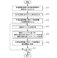
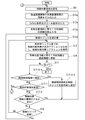
- FIG. 4 is a flowchart showing an operation example (first embodiment) of the train control device 1 shown in FIG.
- the environmental model generation unit 51 reads the setting information 55 from the storage unit 54 according to the input operation of the operator, so that the environmental model such as track route information and train number information can be obtained.
- the definition information is set and the environment model is generated (step S11).
- the action determination unit 52 or the processing flow control unit (not shown) sets the Safety condition and the goal condition according to the input operation of the operator or by reading the condition information 56 from the storage unit 54 (. Step S12).
- the action determination unit 52 (or the processing flow control unit (not shown)) reads the position reservation information 57 from the storage unit 54 according to the input operation of the operator, so that the train position information and the blockage reservation information can be obtained.
- the initial state is set (step S13).
- control logic generation unit 50 uses the environment model generated in step S11, sets the initial state set in step S12 as the initial state of the environment model, and satisfies the Safety condition and goal condition set in step S13. As described above, the control logic generation calculation is performed to generate the control logic (step S14).
- the action determination unit 52 determines the next action of the controlled train T1 based on the control logic generated in step S14, and instructs the controlled train T1 of the action (step S15).
- step S16 the action determination unit 52 updates the train position information and the blockage reservation information to the latest information when a state transition occurs in the environmental model.
- step S17 the regeneration instruction unit 53 determines whether or not to end the process shown in FIG. 4 (step S17), and if it is determined to end (in the case of “Yes” in step S17), it is shown in FIG. If the process ends and it is not determined to end (in the case of "No” in step S17), the process returns to step S14, and the control logic is set to the control logic generator 50 with the state of the environment model at that time as the initial state. Instruct to recreate.
- step S17 for example, when the goal condition is achieved, when the train control on the day is completed, or when the operator performs an input operation instructing the end, it is determined that the process is completed.
- the control logic based on the latest train position information is automatically generated in real time based on the real-time other train position information and the blockage reservation information, and the train control logic is updated during operation. Will be done. Further, in the first embodiment, the control logic automatic generation calculation and update are performed every time some state transition occurs.
- control logic that can correspond to any state transition can be automatically generated in the defined environment model, the control logic satisfies the Safety condition and the goal condition both before and after the controlled train makes some state transition. Therefore, there is no need to generate new control logic during operation.
- not necessarily optimal is, for example, a control logic that completely satisfies the Safety condition and the goal condition, but does not always reach the goal with the minimum number of state transition steps.
- the search is performed. It has the effect of improving the completeness of the state transitions and shortening the calculation time, and enables more accurate calculation. Therefore, each time a state transition occurs, a control logic closer to the optimum can be generated.
- control logic Since the latest state is reflected in the control logic, the time to reach the goal is more appropriate (fewer state transition steps to the goal, or) compared to the control based on the control logic generated before operation.
- the control logic can be used, which leads to more efficient control, shortening of operation time, reduction of power consumption, and reduction of operation cost.
- control logic is, for example, within 24 hours in the case of pre-calculation when using a general computer for servers. Further, when updating the control logic during operation, for example, within a few seconds, which is shorter than the time for the train to move in the block section, is exemplified.
- the timing at which the regeneration instruction unit 53 shown in FIG. 2 updates the control logic is set every time after the state transition of the train T1 to be controlled, whereas in the second embodiment, the timing at which the control logic is updated is set. I'm reducing the frequency.
- the configuration of the second embodiment is the same as the configuration of the first embodiment described with reference to FIGS. 1 and 2, and in the first embodiment and the second embodiment, the regeneration instruction unit 53 shown in FIG. 2 The operation is partially different.
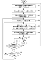
- FIG. 5 is a flowchart showing another operation example (second embodiment) of the train control device 1 shown in FIG.
- the process of step S18 is added to the process shown in FIG.
- the regeneration instruction unit 53 determines whether or not to end the process shown in FIG. 5 (step S17), and if it is determined to end (in the case of “Yes” in step S17).
- step S17 determines whether or not to end the process shown in FIG. 5
- step S18 determines whether or not to update the control logic (in the case of "No" in step S17).
- step S18 the regeneration instruction unit 53 updates the control logic, for example, when the state transition occurs in the environment model a plurality of preset times after the control logic is generated (or last updated). to decide.
- the action determination unit 52 is next to the controlled train T1 based on the control logic generated in step S14.
- the action is determined, and the action is instructed to the train T1 to be controlled (step S15).
- the regeneration instruction unit 53 returns to step S14 and sets the state of the environment model at that time to the control logic generation unit 50 as the initial state. Instructs to recreate (ie update) the control logic.
- the regeneration instruction unit 53 instructs the control logic generation unit 50 to regenerate the control logic each time the state of the environment model changes a plurality of times.
- the amount of calculation and the amount of communication can be reduced as compared with the case where the control logic is updated every time after the state transition as in the first embodiment.
- the third embodiment is different from the first embodiment and the second embodiment in that a process of regenerating (redefining) the environmental model when the environmental model changes is added.
- the configuration of the third embodiment is the same as the configuration of the first embodiment and the second embodiment described with reference to FIGS. 1 and 2, and the third embodiment is shown in comparison with the second embodiment.
- the operation of the regeneration instruction unit 53 shown in 2 is partially different.
- the regeneration instruction unit 53 instructs the control logic generation unit 50 to regenerate the control logic using the changed environment model when the environment model changes.
- FIG. 6 is a flowchart showing another operation example (third embodiment) of the train control device 1 shown in FIG.
- the process of step S17-2 is added to the process shown in FIG. 5 (second embodiment).
- the regeneration instruction unit 53 determines whether or not to end the process shown in FIG. 6 (step S17), and if it is determined to end (in the case of “Yes” in step S17). If the process shown in FIG. 6 is completed and it is not determined to be completed, it is determined in step S17-2 whether or not the environment model of the controlled target area C11 has changed (in the case of "No” in step S17). If the environmental model has changed (if "Yes” in step S17-2), the process returns to step S11, and if the environmental model has not changed (if "No” in step S17-2), step It is determined whether or not to update the control logic in S18.
- the change in the environmental model is a change in the environmental model that was not initially expected and was not considered as a prerequisite for the generation of control logic, and the following abnormal times are mainly assumed.
- (1) When a train other than the train to be controlled stops and becomes inoperable due to an unexpected reason such as a breakdown or an accident.
- (2) When one or more block sections become unusable due to an unexpected reason such as a breakdown or accident.
- the initial route R11 passing through the block section B127 cannot be used.
- the environment model when the blockage section B127 is removed from the control target area C12 is regenerated, and the control logic is generated using the regenerated environment model, for example.
- the route can be changed to a new route R12 that does not pass through the block section B127.
- FIG. 7 is a schematic diagram for explaining an operation example (third embodiment) of the train control device 1 shown in FIG.
- FIG. 7 shows an example of updating to alternative route control when the block section becomes unavailable.
- FIG. 7 schematically shows a controlled target region C12 including the blocked sections B101 to B112 and the closed sections B121 to B132.
- the train T1 to be controlled moves in the direction of the arrow T1a, and the other train T2 moves in the direction of the arrow T2a. Further, the train T1 to be controlled sets the goal condition G1 to reach the block section B112.
- the operator manually inputs the fact to the train control device 1, or automatically detects it by using a camera or a sensor provided on the on-board device 2 or the track 4.
- the train control device 1 (regeneration instruction unit 53) can recognize the train.
- the fourth embodiment will be described with reference to FIGS. 8 to 10.
- the fourth embodiment is different from the first to third embodiments, and as shown in FIGS. 9 and 10, the controlled target area C12 described with reference to FIG. 7 is divided into three partial control areas C12A, C12B and C12C. It is divided and the control logic generation unit 50 generates control logic for each partial control area.
- the area where the controlled train T1 is located is the controlled area.
- the partial control area C12A includes the block sections B101 to B104 and the block sections B121 to B124.
- the partial control area C12B includes a block section B105 to B108 and a block section B125 to B128.
- the partial control area C12C includes a block section B109 to B112 and a block section B129 to B132.
- the train T1 to be controlled and the other train T2 are located in the partial control area C12B, and the other train T3 is located in the partial control area C12C.
- the train T1 to be controlled is located in the block section B125 and is about to move in the direction of the arrow T1a.
- the other train T2 is located in the block section B105 and is about to move in the direction of the arrow T2a.
- the other train T3 is located in the block section B109 and is about to move in the direction of the arrow T3a.
- FIG. 9B shows a case where the other train T2 moves from the block section B105 to the block section B104 and goes out of the partial control area C12B.
- FIG. 10A shows a case where the other train T3 moves from the block section B109 to the block section B108 and enters the partial control area C12B.
- FIG. 10B shows a case where the train T1 to be controlled moves from the block section B125 to the block section B129 and moves from the partial control area C12B to the partial control area C12C.
- FIG. 8 is a flowchart showing another operation example (fourth embodiment) of the train control device 1 shown in FIG. 9 and 10 are schematic views for explaining an operation example (fourth embodiment) of the train control device 1 shown in FIG.
- step S01 at the beginning and the process of step S17-1 are added to the process shown in FIG. 6 (third embodiment).
- step S01 for example, the environment model generation unit 51 (or the control unit for the flow of processing (not shown) divides the control target area C12 into a plurality of (for example, three), and the partial control in which the control target train T1 is located.
- An area for example, a partial control area C12B
- steps S11 to S16 an environmental model such as track route information and train number information is input (step S11) with reference to the partial control area (for example, partial control area C12B) set in the control target area in step S01.
- Safety condition and goal condition input step S12
- initial state of train position information and blockage reservation information step S13
- control logic generation calculation step S14
- next action of the train to be controlled based on the control logic. step S15
- a process of updating the train position information and the blockage reservation information to the latest information step S16
- the regeneration instruction unit 53 determines whether or not to end the process shown in FIG. 8 (step S17), and if it is determined to end (in the case of “Yes” in step S17), the process shown in FIG. If it is not determined to end (in the case of "No” in step S17), it is determined in step S17-1 whether or not the control target area needs to be changed, and the control target area needs to be changed. In that case (in the case of "Yes” in step S17-1), the process is returned to step S01, and the control target area is reset by, for example, the environment model generation unit 51 (or the control unit of the process flow (not shown)). Step S01).
- the regeneration instruction unit 53 moves the control target area 53.
- the environment model generation unit 51 or the control unit of the processing flow (not shown) sets the control target area to the partial control area. It is reset to C12C (step S01).
- step S17-1 when it is not necessary to change the control target area (when “No” in step S17-1), the regeneration instruction unit 53 uses the environmental model of the control target area (for example, partial control area C12B) in step S17-2. It is determined whether or not the environment model has changed, and if the environment model has changed (in the case of "Yes” in step S17-2), the process is returned to step S11, and if the environment model has not changed (step S17-2). (In the case of "No"), it is determined in step S18 whether or not to update the control logic.
- the environmental model of the control target area for example, partial control area C12B
- step S17-2 when the other train T2 moves from the partial control area C12B which is the current control target area to another partial control area C12A as shown in FIG. 9B, or as shown in FIG. 10A.
- the other train T3 moves from another partial control area C12C to the current control target area C12B, the number of trains, which is the information defining the environmental model, changes. It is determined that the environment model has changed (in the case of "Yes" in step S17-2), and the process is returned to step S11.
- the amount of calculation when the controlled area is wide (the number of blocked sections is large), the amount of calculation is large, the calculation time is long, and a large amount of resources for calculation may be required. Then, since one control target area is narrowed, the amount of calculation can be reduced, which contributes to cost reduction and weight reduction by resource reduction.
- the control logic when the control logic is not updated during operation only by dividing the control target area into a plurality of parts, the control logic is generated on the assumption that trains other than the control target train enter and exit the control target area. There is a need to. In that case, the number of states to be assumed is large, and it may take more time than the practical time to calculate the control logic generation, or the calculation may become impossible because the capacity of the computer such as insufficient memory is exceeded. In the fourth embodiment, the calculation time is shortened by updating the control logic during operation, which is within the practical calculation time.
- FIG. 11 is a block diagram showing another configuration example (fifth embodiment) of the train control device 1 (train control device 1a in FIG. 11) and the on-board device 2 shown in FIG.
- FIG. 12 is a flowchart showing an operation example (fifth embodiment) of the train control device 1a shown in FIG.
- the train control device 1a (corresponding to the train control device 1 shown in FIG. 2) newly adds the generation instruction unit 61 as compared with the first to third embodiments.
- the process of step S17-0-1 and the process of step S17-0-2 are added to the process shown in FIG. 8 (fourth embodiment).
- the processing contents of steps S11 to S14 (fourth embodiment) shown in FIG. 8 are partially changed (indicated as steps S11a to S14a in FIG. 12). ..
- the additional generation instruction unit 61 is placed in a partial control area C12C different from the partial control area C12B in which the control target train T1 shown in FIG. 9A exists, for example.
- the control logic generation unit 50 is instructed to generate control logic for another partial control area C12C in addition to the generation of control logic for the partial control area C12B in which the train T1 to be controlled exists.
- the case of approaching another partial control area is, for example, when the control target train enters the block section of the control target area near the boundary with the other area.
- the additional generation instruction unit 61 instructs the control logic generation unit 50 to generate the control logic of another control area on the other side of the boundary.
- the definition near the boundary exemplifies the case where the train to be controlled enters the block section in which the number of block sections that move before reaching the block section adjacent to the boundary is 0 to 2.
- the regeneration instruction unit 53 determines in step S17 whether or not to end the process shown in FIG. When it is determined to end (in the case of "Yes" in step S17), the regeneration instruction unit 53 ends the process shown in FIG.
- the additional generation instruction unit 61 determines whether or not the train to be controlled is approaching the adjacent (partial) control area. (Step S17-0-1). When the train to be controlled is approaching the adjacent (partial) control area (when “Yes” in step S17-0-1), the additional generation instruction unit 61 adds the adjacent control area to the generation target of the control logic ( Step S17-0-2), the process returns to step S11a. When the adjacent control area is added to the control logic generation target, in steps S11a to S13a, the track route information and the number of trains are based on the partial control area added to the control logic generation target in step S17-0-2.
- step S11a Input of an environment model such as information (step S11a), input of safety conditions and goal conditions (step S12a), and input of initial states of train position information and blockage reservation information (step S13a) are executed. Further, in step S14a, the generation calculation of the control logic based on the controlled target area and the generation calculation of the control logic based on the adjacent control area are performed.
- step S17-1 when the additional generation instruction unit 61 determines that the train to be controlled is not approaching the adjacent (partial) control area (when "No" in step S17-0-1), the regeneration instruction unit 53 is adjacent. It is determined whether or not it is necessary to change the controlled target area (step S17-1).
- the blank time for control can be eliminated by predicting the change in the environmental model when entering the adjacent control area and generating the control logic in advance.
- FIG. 13 is a block diagram showing another configuration example (sixth embodiment) of the train control device 1 (train control device 1b in FIG. 13) and the on-board device 2 shown in FIG.
- FIG. 14 is a schematic diagram for explaining an operation example (sixth embodiment) of the train control device 1b shown in FIG.
- the train control device 1b (corresponding to the train control device 1a shown in FIG. 11) has a new area redefinition unit 62 as compared with the fifth embodiment.
- the area redefinition unit 62 redefines a partial control area according to the position of the train to be controlled, for example, as shown in FIG.
- the partial control region C12A includes the block sections B101 to B104 and the block sections B121 to B124.
- the partial control area C12B includes a block section B105 to B108 and a block section B125 to B128.
- the partial control area C12C includes a block section B109 to B112 and a block section B129 to B132.
- the train T1 to be controlled is located in the block section B128 and is about to move in the direction of the arrow T1a.
- the other train T2 is located in the block section B106 and is about to move in the direction of the arrow T2a.
- the other train T3 is located in the block section B111 and is about to move in the direction of the arrow T3a.
- FIG. 14B shows an example after redefining the partial control area.
- the partial control region C12A includes the block sections B103 to B106 and the block sections B123 to B126.
- the partial control area C12B includes a block section B107 to B110 and a block section B127 to B130.
- the partial control region C12C includes block sections B111 to B112 and block sections B131 to B132.
- the train T1 to be controlled is located in the block section B128 and is about to move in the direction of the arrow T1a.
- the other train T2 is located in the block section B106 and is about to move in the direction of the arrow T2a.
- the other train T3 is located in the block section B111 and is about to move in the direction of the arrow T3a.
- the control logic is suddenly generated near the boundary, so in the case of control that goes back and forth between the boundaries, the calculation will be repeated many times. Therefore, in the sixth embodiment, the control target area is set so that the control target train is located near the center of the control target area when the train is about to approach the boundary so that the control target train does not reach the vicinity of the boundary of the control target area. Redefine.
- the controlled area may be redefined so that a constant number of block sections existing in the traveling direction in the control area is always secured. According to this configuration, more stable control becomes possible in the sixth embodiment.
- control area of the partial control area C12A and the partial control area C12C is not essential for the control of the train to be controlled, but for example, when the fourth embodiment and the fifth embodiment are used together depending on the situation, the partial control area C12A and Definition / redefinition of the partial control area C12C is indispensable.
- a computer 12 for generating control logic (control logic generation unit 50) and some functional components of the central control device 11 (for example, an action determination unit 52, a regeneration instruction).
- Section 53, additional generation instruction section 61, area redefinition section 62, etc. may be mounted on the train T1 to be controlled.
- the computer 12 attached to the central control device 11 creates the control logic for all trains. Further, since the communication related to the collection of the state information and the control instruction is also concentrated on the central control device 11, the burden is concentrated on the central control device 11.
- the calculation and communication load is distributed to each train, and the central control device 11 can construct an inexpensive and lightweight system. Further, since autonomous control is possible for each train, train control can be continued without stopping the control of all the lines when the central control device 11 fails.
- FIG. 15 is a schematic block diagram showing the configuration of a computer according to at least one embodiment.
- the computer 90 includes a processor 91, a main memory 92, a storage 93, and an interface 94.
- the above-mentioned train control device 1, central control device 11, and computer 12 are mounted on the computer 90.
- the operation of each processing unit described above is stored in the storage 93 in the form of a program.
- the processor 91 reads a program from the storage 93, expands it into the main memory 92, and executes the above processing according to the program. Further, the processor 91 secures a storage area corresponding to each of the above-mentioned storage units in the main memory 92 according to the program.
- the program may be for realizing a part of the functions exerted on the computer 90.
- the program may exert its function in combination with another program already stored in the storage or in combination with another program mounted on another device.
- the computer may include a custom LSI (Large Scale Integrated Circuit) such as a PLD (Programmable Logic Device) in addition to or in place of the above configuration.
- PLDs include PAL (Programmable Array Logic), GAL (Generic Array Logic), CPLD (Complex Programmable Logic Device), and FPGA (Field Programmable Gate Array).
- PLDs Programmable Integrated Circuit
- PAL Programmable Array Logic
- GAL Generic Array Logic
- CPLD Complex Programmable Logic Device
- FPGA Field Programmable Gate Array
- Examples of the storage 93 include HDD (Hard Disk Drive), SSD (Solid State Drive), magnetic disk, magneto-optical disk, CD-ROM (Compact Disc Read Only Memory), and DVD-ROM (Digital Versatile Disc Read Only Memory). , Semiconductor memory and the like.
- the storage 93 may be internal media directly connected to the bus of the computer 90, or external media connected to the computer 90 via the interface 94 or a communication line. When this program is distributed to the computer 90 via a communication line, the distributed computer 90 may expand the program in the main memory 92 and execute the above processing.
- the storage 93 is a non-temporary tangible storage medium.
- control logic since the control logic can be updated during train operation, it can be generated without increasing the calculation cost as compared with the case where the efficient control logic is not updated.
Landscapes
- Engineering & Computer Science (AREA)
- Mechanical Engineering (AREA)
- Train Traffic Observation, Control, And Security (AREA)
Abstract
所定の制御対象領域に含まれる軌道を構成する複数の閉塞区間の数及び接続形態と前記軌道上に存在する列車の数によって定義され、制御対象の前記列車である1の制御対象列車の位置、0以上の他の前記列車の位置、前記各閉塞区間の予約の有無等の組み合わせによって離散的に状態が変化する環境モデルを用いて、所定条件を満たすように、前記環境モデルの前記状態に応じて、前記環境モデルを状態遷移させるロジックである制御ロジックを生成する制御ロジック生成部と、前記所定条件が満たされる前に、前記制御ロジック生成部に対してそのときの前記環境モデルの前記状態を初期状態として前記制御ロジックの再生成を指示する再生成指示部とを備える列車制御装置である。
Description
本発明は、列車制御装置、方法及びプログラムに関する。
本願は、2019年6月26日に日本に出願された特願2019-118980号について優先権を主張し、その内容をここに援用する。
本願は、2019年6月26日に日本に出願された特願2019-118980号について優先権を主張し、その内容をここに援用する。
特許文献1に記載されている列車運行制御装置は、ネットワークを介して接続される、鉄道路線の各閉塞区間の始点に設置された信号機を制御対象として制御命令を生成して、個々の信号機に送信する。この特許文献1に記載されている列車運行制御装置は、状態情報記録部と、信号制御部と、制御命令記録部と、入出力制御部とを備える。状態情報記録部は、信号機の状態情報、列車位置情報源から得られる列車の現在位置情報、及び鉄道路線の特定の閉塞区間に設けられる設備の状態情報を、ネットワークを介して取得して、ログファイルに記録する。また、信号制御部は、ログファイルから最新の信号機の状態情報、列車の現在位置情報、及び設備の状態情報を取得して、信号機に対する制御指令を作成する。また、制御命令記録部は、作成された制御命令及び端末から送信されるマニュアル操作による制御命令をログフィルに記録する。また、入出力制御部は、信号制御部で作成された制御命令を、ネットワークを介して信号機に送信する。そして、信号制御部は、列車が存在する閉塞区間の次に位置する、列車が進行しようとする閉塞区間を、列車の運行ダイヤに基づいて、信号機をまとめて制御しなければならない複数の閉塞区間を予約対象閉塞区間として特定し、ログファイルからネットワークを介して取得した最新の信号機の状態情報、列車の現在位置情報及び設備の状態情報からみて、予約対象閉塞区間に属するすべての閉塞区間において列車を通過させてはいけない閉塞区間が存在しない場合は、予約対象閉塞区間の中の全ての閉塞区間の始点に存在する信号機を全て通行許可信号に制御する。
特許文献1に記載されている列車運行制御装置では、複数の閉塞区間を対象として通過できるか否かを判断した結果に基づき運行制御が行われる。このような構成では、例えば、運行制御の自由度が大きい場合に最適解を求めるとき、計算時間が長くなる等、計算コストが増加してしまうという課題がある。すなわち、例えば通過することができる制御状態の組み合わせが複数組存在するような場合に、通過時間が最短となる制御状態の組み合わせ等の最適解を求めるようとすると、計算時間が長くなる等、計算コストが増加してしまうという課題がある。
本発明は、列車制御に係る計算コストの増加を抑えることができる列車制御装置、方法及びプログラムを提供する。
本発明の一態様は、所定の制御対象領域に含まれる軌道を構成する複数の閉塞区間の数及び接続形態と前記軌道上に存在する列車の数によって定義され、制御対象の前記列車である1の制御対象列車の位置、0以上の他の前記列車の位置、及び前記各閉塞区間の予約の有無等の組み合わせによって離散的に状態が変化する環境モデルを用いて、列車を制御する列車制御装置であって、前記制御対象領域を通過するための条件である所定条件を満たすように、前記環境モデルの前記状態に応じて、前記制御対象列車による、「前記閉塞区間の予約又は予約の解除」、「予約した前記閉塞区間への移動」、又は、「現在位置している前記閉塞区間内での待機」の各アクションのうちのいずれかを選択し、選択の結果に応じて前記環境モデルを状態遷移させるロジックである制御ロジックを生成する制御ロジック生成部と、前記所定条件が満たされるまで、生成された前記制御ロジックに基づき、前記環境モデルの前記状態に応じた前記制御対象列車が行う前記アクションを順次決定するアクション決定部と、前記所定条件が満たされる前に、前記制御ロジック生成部に対してそのときの前記環境モデルの前記状態を初期状態として前記制御ロジックの再生成を指示する再生成指示部とを備える列車制御装置である。
また、本発明の一態様は、上記列車制御装置であって、前記所定条件が、目標状態として到達すべき条件と、到達してはならない条件とを含む。
また、本発明の一態様は、上記列車制御装置であって、前記制御ロジックは、前記制御対象領域に含まれる各閉塞区間の状態遷移の流れと前記制御対象列車が順次に行う各前記アクションとの対応づけを示す情報を含む。
また、本発明の一態様は、上記列車制御装置であって、前記再生成指示部は、前記環境モデルの前記状態が複数回変化する毎に、前記制御ロジック生成部に対して前記制御ロジックの再生成を指示する。
また、本発明の一態様は、上記列車制御装置であって、前記再生成指示部は、前記環境モデルが変化した場合に、前記制御ロジック生成部に対して変化した前記環境モデルを用いた前記制御ロジックの再生成を指示する。
また、本発明の一態様は、上記列車制御装置であって、前記制御ロジック生成部が、前記制御対象領域を複数に分割した領域である部分制御領域毎に前記制御ロジックを生成するものであり、前記再生成指示部が、前記制御対象列車が存在する前記部分制御領域外から他の前記列車が入った場合、又は、前記制御対象列車が存在する前記部分制御領域から他の前記列車が出た場合に、前記制御ロジック生成部に対して前記制御ロジックの再生成を指示する。
また、本発明の一態様は、上記列車制御装置であって、前記制御対象列車が存在する前記部分制御領域とは別の前記部分制御領域に前記制御対象列車が接近した場合に、前記制御ロジック生成部に対して、前記制御対象列車が存在する前記部分制御領域に対する前記制御ロジックの生成に追加して、前記別の部分制御領域に対する前記制御ロジックの生成を指示する追加生成指示部をさらに備える。
また、本発明の一態様は、上記列車制御装置であって、前記制御対象列車の位置に応じて前記部分制御領域を再定義する領域再定義部をさらに備える。
また、本発明の一態様は、上記列車制御装置であって、前記列車に搭載されている。
また、本発明の一態様は、所定の制御対象領域に含まれる軌道を構成する複数の閉塞区間の数及び接続形態と前記軌道上に存在する列車の数によって定義され、制御対象の前記列車である1の制御対象列車の位置、0以上の他の前記列車の位置、及び前記各閉塞区間の予約の有無等の組み合わせによって離散的に状態が変化する環境モデルを用いて列車を制御する方法であって、前記制御対象領域を通過するための条件である所定条件を満たすように、前記環境モデルの前記状態に応じて、前記制御対象列車による、「前記閉塞区間の予約又は予約の解除」、「予約した前記閉塞区間への移動」、又は、「現在位置している前記閉塞区間内での待機」の各アクションのうちのいずれかを選択するステップと、選択の結果に応じて、前記環境モデルを状態遷移させるロジックである制御ロジックを生成するステップと、前記所定条件が満たされるまで、生成された前記制御ロジックに基づき、前記環境モデルの前記状態に応じた前記制御対象列車が行う前記アクションを順次決定するステップと、前記所定条件が満たされる前に、そのときの前記環境モデルの前記状態を初期状態として前記制御ロジックの再生成をするステップとを含む列車を制御する方法である。
また、本発明の一態様は、所定の制御対象領域に含まれる軌道を構成する複数の閉塞区間の数及び接続形態と前記軌道上に存在する列車の数によって定義され、制御対象の前記列車である1の制御対象列車の位置、0以上の他の前記列車の位置、及び前記各閉塞区間の予約の有無等の組み合わせによって離散的に状態が変化する環境モデルを用いて列車を制御する方法であって、前記制御対象領域を通過するための条件である所定条件を満たすように、前記環境モデルの前記状態に応じて、前記制御対象列車による、「前記閉塞区間の予約又は予約の解除」、「予約した前記閉塞区間への移動」、又は、「現在位置している前記閉塞区間内での待機」の各アクションのうちのいずれかを選択するステップと、選択の結果に応じて、前記環境モデルを状態遷移させるロジックである制御ロジックを生成するステップと、前記所定条件が満たされるまで、生成された前記制御ロジックに基づき、前記環境モデルの前記状態に応じた前記制御対象列車が行う前記アクションを順次決定するステップと、前記所定条件が満たされる前に、そのときの前記環境モデルの前記状態を初期状態として前記制御ロジックの再生成をするステップとを列車を制御する装置を構成するコンピュータに実行させるプログラムである。
本発明の各態様によれば、列車運行中に制御ロジックを更新することができるので、効率的な制御ロジックを更新しない場合と比較して計算コストを増加させることなく生成することができる。
以下、図面を参照して本発明の実施形態について説明する。なお、各図において、同一または対応する構成には同一の符号を用いて説明を適宜省略する。
〈第1実施形態〉
本発明の第1実施形態について説明する。図1は、本発明の実施形態に係る列車制御装置1の構成例を示す構成図である。図1において、軌道システム3は、列車制御装置1と、軌道(「軌道路線」とも呼ばれる。)4と、1又は複数の列車T1、T2等を備える。軌道4は、複数の閉塞区間(「閉塞区間」は「閉塞」(閉そく)とも称呼、記載される。)B1、B2、B3、B4、B5等から構成されている。各列車T1及びT2は、軌道4上を走行する1又は複数の車両から構成されている。各列車T1及びT2は、車上装置2をそれぞれ備える。
本発明の第1実施形態について説明する。図1は、本発明の実施形態に係る列車制御装置1の構成例を示す構成図である。図1において、軌道システム3は、列車制御装置1と、軌道(「軌道路線」とも呼ばれる。)4と、1又は複数の列車T1、T2等を備える。軌道4は、複数の閉塞区間(「閉塞区間」は「閉塞」(閉そく)とも称呼、記載される。)B1、B2、B3、B4、B5等から構成されている。各列車T1及びT2は、軌道4上を走行する1又は複数の車両から構成されている。各列車T1及びT2は、車上装置2をそれぞれ備える。
なお、閉塞区間は、一つの列車しか進入が許されない区間である。また、ある閉塞区間へ進入する場合、進入に先立って当該閉塞区間を予約し、予約できた場合に当該閉塞区間へ進入することができる。各閉塞区間の予約は一つの列車しか許されない。
列車制御装置1は、中央制御装置11と、計算機12を備える。中央制御装置11は、1又は複数のコンピュータとその周辺装置とから構成され、各列車T1及びT2の位置情報を元に各列車T1及びT2を論理制御(離散的制御)によって遠隔制御する。中央制御装置11は、各車上装置2が送信した各列車T1及びT2の位置情報を受信し、受信した各列車T1及びT2の位置情報を元に予め生成した制御ロジックに従い各列車T1及びT2に対して制御命令を送り、各列車T1及びT2を論理制御する。制御ロジックは論理制御のプログラムである(詳細は後述する。)。計算機12は、制御ロジックを計算し、生成する。その際、列車制御装置1は、軌道4上で予め定めた領域を制御対象領域C11とし、制御対象領域C11内に位置する特定の制御対象の列車(制御対象列車)毎に制御ロジックを生成する。図1に示す例では、制御対象領域C11は閉塞区間B1、B2、B3、B4及びB5を含む。この場合、閉塞区間B3は一つの線路が二つの線路に分岐する部分であり、枝分かれした部分を含めて一つの閉塞区間とみなす。閉塞区間を示す破線のブロック内の矢印は、その閉塞区間にいる列車が次に進める方向を示す。
閉塞区間B1は閉塞区間B2に接続され、閉塞区間B2は閉塞区間B3に接続され、閉塞区間B3は閉塞区間B4と閉塞区間B5に分岐部を介して接続されている。また、閉塞区間B1に列車T2が位置し、閉塞区間B5に列車T1が位置している。また、閉塞区間B1からは、白抜きの矢印で示す閉塞区間B2方向への移動が許されている。閉塞区間B2からは、黒塗りの矢印で示す閉塞区間B3方向への移動が許されている。閉塞区間B3からは、閉塞区間B2から進入した列車に対して閉塞区間B4方向への移動が、また、閉塞区間B5から進入した列車に対して閉塞区間B2方向への移動が、許されている。閉塞区間B5からは、白抜きの矢印で示す閉塞区間B3方向への移動が許されている。なお、白抜きの矢印は、当該閉塞区間が予約された状態を示し、黒塗りの矢印は、当該閉塞区間の予約が解除された状態を示す。
本実施形態において、制御ロジックとは、複数の閉塞区間B1~B5に分割された軌道4と、軌道4上に存在する一つの制御対象列車(以下、列車T1を制御対象列車T1とする)と、同じく軌道4上に存在する0以上の他列車(以下、列車T2を他列車T2とする)とで構成された「環境モデル」上において、列車T1及びT2の位置関係や閉塞区間の予約状況(環境モデルの状態)を元に、制御対象列車T1のアクションを、「閉塞区間の予約/解除」、「予約した閉塞区間への移動」、「現在いる閉塞区間内での待機」のうちから決定するロジックである。この場合、環境モデルは、制御対象の環境を表すモデルであり、所定の制御対象領域C11に含まれる軌道4を構成する複数の閉塞区間B1~B5の数(この場合5個)及び接続形態(各閉塞区間B1~B5の接続と進行方向の関係)と、軌道4上に存在する列車の数(この場合2個)によって定義される。そして、環境モデルは、制御対象の列車である1の制御対象列車T1の位置(この場合閉塞区間B5)、0以上の他の列車T2の位置(この場合閉塞区間B1)、各閉塞区間の予約の有無等の組み合わせによって離散的に状態が変化する。なお、以下では、制御対象列車T1を(他列車T2に対し)自列車と呼ぶ場合がある。また、環境モデルを定義する情報のうち、軌道を形成する閉塞区間の数と接続形態を示す情報を、軌道路線情報と呼ぶ場合がある。
また、本実施形態において、制御ロジックは、Safety条件(安全条件)及びゴール条件を満たす必要がある。
Safety条件とは、例えば「他列車がどのような動きをした場合でも、衝突などの危険な結果に陥らない」、「制御対象列車がどのような制御をしても身動きできなくなるデッドロックに陥らない」等の、いかなる場合でも到達してはならない条件である。
ゴール条件とは、例えば、「車庫から出庫した後、指定された駅に到着する」、「制御対象領域内の特定の閉塞区間に到達する」などの目標状態として必ず到達すべき条件である。なお、ゴール条件は、「ある中間状態を満たした後、他の最終状態に至る」等の複数の目標状態の組み合わせで構成される場合もある。
本実施形態における具体事例は、信号制御等の他の安全システムにより、ある閉塞区間には一つの列車しか進入できない条件が担保されている事を前提とする。よって衝突は起こりえず、本実施形態が対象とする制御ロジックは、「デッドロックに陥ることなくゴール条件を達成する」事が目的である。すなわち、本実施形態において制御ロジックは、制御対象領域を通過するための条件である所定条件を満たすように生成される。ここで、所定条件は、「ゴール条件を達成する」という目標状態として到達すべき条件と、「デッドロックに陥ることなく」という到達してはならない条件とを含む。また、制御ロジックは、制御対象領域に含まれる各閉塞区間の状態遷移の流れと制御対象列車が順次に行う各アクションとの対応づけを示す情報を含んでいる。
本実施形態では、連続的時間の概念は無く、ステップが進む度に不連続に状態が遷移する離散的状態遷移における制御ロジックのみを扱う。また、本実施形態では、列車が閉塞区間間を移動する際、一つの列車が二つの閉塞区間を同時にまたぐような中間状態は存在しないとして説明するが、同時にまたいでいる状態を一つの離散的状態と定義することで、そのような中間状態を含んだ離散的状態遷移を考慮してもよい。
制御ロジックは、環境モデルの状態に従って、制御対象列車が取るアクションを提示する。ゴール条件を達成するための制御対象列車が取ってよいアクション(ゴール条件に到達できるアクション)を複数提示するような制御ロジックを生成してもよい。実際の運用上は、提示された複数のアクションの中から、何らかの方法で一つのアクションだけを選んで実行する事となる。
なお、本実施形態における「環境モデル」と「制御ロジック」については次のようにまとめることができる。すなわち、本実施形態において、「環境モデル」は、(1)軌道を形成する閉塞区間の数および接続形態(接続形状)及び(2)軌道上に存在する列車の数で定義される。そして、「環境モデル」は、制御対象列車の位置、他列車の位置、各閉塞区間の予約の有無(自列車の予約か、他列車の予約か)などの組み合わせに基づく離散的な状態をとる(離散的に状態遷移する)。例えば、ある状態(1)は、「制御対象列車の位置=〇〇、他列車(1)の位置=××、…、閉塞区間(1)=予約なし、閉塞区間(2)=予約なし、…」である。また、他の状態(2)は、「制御対象列車の位置=△△、他列車(1)の位置=□□、…、閉塞区間(1)=予約なし、閉塞区間(2)=他列車(1)の予約あり、…」である。なお、「環境モデル」の状態は、列車ごとに定義される。例えば、列車が3台(列車(A)、(B)、(C))の場合、列車(A)の制御に用いられる環境モデルの状態は、(a)制御対象列車(列車A)の位置、(b)他列車(列車(B)、(C)それぞれ)の位置、(c)各閉塞区間の自列車(列車(A))の予約の有無、(d)各閉塞区間の他列車(列車(B)、(C))の予約の有無、で決定される。また、列車(B)の制御に用いられる環境モデルの状態、列車(C)の制御に用いられる環境モデルの状態も同様にある。
また、本実施形態において、「制御ロジック」とは、「環境モデル」の状態に応じて、制御対象列車に対し、「閉塞区間の予約/解除」、「予約した閉塞区間への移動」、「現在いる閉塞区間内での待機」のアクションのうちのいずれかを決定し、「環境モデル」を状態遷移させるロジックである。また、「制御ロジック」は、(1)制御対象列車が現在いる閉塞区間から目的の閉塞区間に到達するように生成され、かつ、(2)デッドロックが生じないように生成される。
なお、本実施形態における「制御ロジック」は、オープンソースとして公開されているツールであるMTSA(Modal Transition System Analyzer)などを利用して、自動生成することができる。MTSAは、は、インペリアル・カレッジ・ロンドン(Distributed Software Engineering (DSE) group at Imperial College London)とブエノスアイレス大学(the Laboratory on Foundations and Tools for Software Engineering (LaFHIS) at University of Buenos Aires)で共同開発された、自動生成ツールであり、形式的に記述された環境モデルと要求条件を入力とし、正しさが保証された仕様モデル(環境モデルの状態)をゲーム理論に基づいて自動生成する(URL:http://mtsa.dc.uba.ar)。ただし、これに限らず、「制御ロジック」は、例えば特許文献1に記載されているように複数の条件判断を行う処理を組み合わせるプログラムを用いて生成してもよい。
次に、本実施形態に係る論理制御(離散的制御)の例について図16~図18を参照して説明する。図16~図18は、図1に示す列車制御装置1の説明に用いる模式図である。
図16の(a)~(i)は、軌道4上に制御対象列車T1だけが存在する場合、「閉塞区間B5にいる列車T1が閉塞区間B4に移動する事」というゴール条件を達成するための最小の状態遷移数での制御手順を示す。白抜きの矢印を含む閉塞区間は、進入予約された閉塞区間であり、予約を実施した列車以外はその閉塞区間に入れない。また、この例では、分岐を含む閉塞区間B3から右側の閉塞区間B4に移動するためには、一旦閉塞区間B2に進入した後方向転換し再び閉塞区間B3に進入した後、閉塞区間B4に進入する必要がある。
図16の(a)は、制御対象列車T1が閉塞区間B5に位置し、閉塞区間B5が制御対象列車T1に対して予約されている状態を示す。図16の(b)は、制御対象列車T1が閉塞区間B5に位置し、閉塞区間B5と閉塞区間B3が制御対象列車T1に対して予約されている状態を示す。図16の(c)は、制御対象列車T1が閉塞区間B3に移動し、閉塞区間B3が制御対象列車T1に対して予約され、閉塞区間B5の予約が解除された状態を示す。図16の(d)は、制御対象列車T1が閉塞区間B3に位置し、閉塞区間B3と閉塞区間B2が制御対象列車T1に対して予約されている状態を示す。図16の(e)は、制御対象列車T1が閉塞区間B2に移動し、閉塞区間B2が制御対象列車T1に対して予約され、閉塞区間B3の予約が解除された状態を示す。図16の(f)は、制御対象列車T1が閉塞区間B2に位置し、閉塞区間B2と閉塞区間B3が制御対象列車T1に対して予約されている状態を示す。図16の(g)は、制御対象列車T1が閉塞区間B3に移動し、閉塞区間B3が制御対象列車T1に対して予約され、閉塞区間B2の予約が解除された状態を示す。図16の(h)は、制御対象列車T1が閉塞区間B3に位置し、閉塞区間B3と閉塞区間B4が制御対象列車T1に対して予約されている状態を示す。図16の(i)は、制御対象列車T1が閉塞区間B4に移動し、閉塞区間B4が制御対象列車T1に対して予約され、閉塞区間B3の予約が解除された状態を示す。
図17の(a)~(c)は、参考例として、軌道4上に制御対象列車T1及び一つの他列車T2が存在する場合に、両方が永遠に動けなくなるデッドロックに陥った状態を示す。この場合、デッドロックは、向かい合う閉塞区間を2台の列車T1及びT2がそれぞれ予約したために生じた。ただし、本実施形態では、このような制御ロジックは作成されない。
図17の(a)は、制御対象列車T1が閉塞区間B5に位置し、他列車T2が閉塞区間B1に位置し、閉塞区間B5が制御対象列車T1に対して予約され、閉塞区間B1が他列車T2に対して予約されている状態を示す。図17の(b)は、制御対象列車T1が閉塞区間B5に位置し、閉塞区間B5と閉塞区間B3が制御対象列車T1に対して予約され、他列車T2が閉塞区間B1に位置し、閉塞区間B1と閉塞区間B2が他列車T2に対して予約されている状態を示す。図17の(c)は、制御対象列車T1が閉塞区間B3に移動し、閉塞区間B3が制御対象列車T1に対して予約され、閉塞区間B5の予約が解除され、他列車T2が閉塞区間B2に移動し、閉塞区間B2が他列車T2に対して予約され、閉塞区間B1の予約が解除された状態を示す。
図18の(a)~(i)は、軌道4上に制御対象列車T1及び一つの他列車T2が存在する場合、デッドロックせずゴール条件までたどり着いた事例を示す。制御対象列車T1が分岐を超えてもう一つ先までの閉塞区間を予約することで、デッドロックを回避している。
なお、列車1編成を構成する車両数は1車両以上で上限は無いが、列車の長さは最も短い閉塞区間の長さよりも短いものとする。
図18の(a)は、制御対象列車T1が閉塞区間B5に位置し、他列車T2が閉塞区間B1に位置し、閉塞区間B5が制御対象列車T1に対して予約され、閉塞区間B1が他列車T2に対して予約されている状態を示す。図18の(b)は、制御対象列車T1が閉塞区間B5に位置し、他列車T2が閉塞区間B1に位置し、閉塞区間B5と閉塞区間B2が制御対象列車T1に対して予約され、閉塞区間B1が他列車T2に対して予約されている状態を示す。図18の(c)は、制御対象列車T1が閉塞区間B5に位置し、他列車T2が閉塞区間B1に位置し、閉塞区間B5と閉塞区間B2と閉塞区間B3が制御対象列車T1に対して予約され、閉塞区間B1が他列車T2に対して予約されている状態を示す。図18の(d)は、制御対象列車T1が閉塞区間B3に移動し、他列車T2が閉塞区間B1に位置し、閉塞区間B2と閉塞区間B3が制御対象列車T1に対して予約され、閉塞区間B1が他列車T2に対して予約され、閉塞区間B5の予約が解除された状態を示す。図18の(e)は、制御対象列車T1が閉塞区間B2に移動し、他列車T2が閉塞区間B1に位置し、閉塞区間B2が制御対象列車T1に対して予約され、閉塞区間B1が他列車T2に対して予約され、閉塞区間B3の予約が解除された状態を示す。図18の(f)は、制御対象列車T1が閉塞区間B2に位置し、他列車T2が閉塞区間B1に位置し、閉塞区間B2と閉塞区間B3が制御対象列車T1に対して予約され、閉塞区間B1が他列車T2に対して予約されている状態を示す。図18の(g)は、制御対象列車T1が閉塞区間B3に移動し、他列車T2が閉塞区間B1に位置し、閉塞区間B3が制御対象列車T1に対して予約され、閉塞区間B1が他列車T2に対して予約され、閉塞区間B2の予約が解除された状態を示す。図18の(h)は、制御対象列車T1が閉塞区間B3に位置し、他列車T2が閉塞区間B1に位置し、閉塞区間B3と閉塞区間B4が制御対象列車T1に対して予約され、閉塞区間B1が他列車T2に対して予約されている状態を示す。図18の(i)は、制御対象列車T1が閉塞区間B4に移動し、他列車T2が閉塞区間B1に位置し、閉塞区間B4が制御対象列車T1に対して予約され、閉塞区間B1が他列車T2に対して予約され、閉塞区間B3の予約が解除された状態を示す。
次に、図2を参照して、図1に示す列車制御装置1と車上装置2の機能的な構成例について説明する。図2は、図1に示す列車制御装置1と車上装置2の構成例を示すブロック図である。図2に示すように、列車制御装置1において、計算機12は、制御ロジック生成部50を有する。また、列車制御装置1において、中央制御装置11は、環境モデル生成部51と、アクション決定部52と、再生成指示部53と、記憶部54を有する。ここで、制御ロジック生成部50と、環境モデル生成部51と、アクション決定部52と、再生成指示部53と、記憶部54は、計算機12及び中央制御装置11を構成する1若しくは複数のコンピュータ及びそのコンピュータの周辺装置等のハードウェアと、そのコンピュータが実行するプログラム等のソフトウェアとの組み合わせで構成される機能的構成要素である。また、記憶部54は、設定情報55と、条件情報56と、位置予約情報57と、制御ロジック58を記憶する。
設定情報55は、環境モデルを生成する際に用いる各種情報を含む。この各種情報とは、例えば、制御対象領域C11等に含まれる軌道4を構成する複数の閉塞区間B1~B5等の数及び接続形態(軌道路線情報という)と軌道4上に存在する列車T1、T2等の数の情報(列車数情報という)等である。
条件情報56は、Safety条件と列車毎のゴール条件を表す情報等を含む。
位置予約情報57は、閉塞区間毎に、列車の存在の有無及び存在する場合にどの列車が存在しているのかを表す情報(列車位置情報という)、予約の有無を表す情報(閉塞予約情報という)等であって、制御ロジックを生成する際の初期値として使用される情報、列車制御によって変化した履歴や最新の状態を表す情報等を含む。
制御ロジック58は、制御ロジック生成部50が生成した列車毎の制御ロジックを表す情報を含む。ここで、図3を参照して制御ロジック58の構成例について説明する。図3は、図2に示す制御ロジック58の構成例を示す模式図である。図3は、状態遷移表の形式で示した制御ロジック58の例を示す。図3に示す制御ロジック58は、図1に示す制御対象領域C11が含む軌道4に対応する環境モデルを状態遷移させるロジックであり、状態番号1、2、3、4、5、…から構成される一連の制御ロジックと、状態番号12、13、14、…から構成される他の一連の制御ロジックとを含む。状態番号1、2、3、4、5、…から構成される一連の制御ロジックは、初期状態で、図18の(a)に示すように制御対象列車T1(図3では「自列車」と表記)が閉塞区間B5に位置し(在線し)、他列車T2が閉塞区間B1に位置し、制御対象列車T1が閉塞区間B4を目標位置として移動する場合の状態遷移と制御対象列車T1のアクションを示す情報を含む。状態番号1が図18の(a)に対応し、状態番号2が図18の(b)に対応し、状態番号3が図18の(c)に対応し、状態番号4が図18の(d)に対応し、状態番号5が図18の(e)に対応する。図3に示す制御ロジック58によれば、制御対象領域C11の各閉塞区間B1~B5の状態が例えば状態番号1の状態に一致した場合、閉塞区間B2を予約するとのアクションが選択される。そして、状態番号1に規定されたアクションが実行されたことに続いて各閉塞区間B1~B5の状態が状態番号2の状態に一致した場合、閉塞区間B3を予約するとのアクションが選択される。一方、状態番号12、13、14、…から構成される一連の制御ロジックは、閉塞区間B2が他列車T2によって予約済みであるため、制御対象列車T1による予約ができず制御対象列車T1が待機している場合である。状態番号12、13、14、…から構成される一連の制御ロジックは、初期状態で、図18の(a)に示すように制御対象列車T1が閉塞区間B5に位置し、他列車T2が閉塞区間B1に位置し、制御対象列車T1が閉塞区間B4を目標位置として移動する場合で、他列車T2が閉塞区間B4を目標位置として制御対象列車T1より先に移動するときの状態遷移の内容と制御対象列車T1のアクションを示す情報を含む。状態番号12、13及び14では、制御対象列車T1は閉塞区間B5に位置し、アクションは「待機」である。
なお、図3に示す制御ロジック58では、列車が在線している閉塞区間は必ず在線列車による予約がされており、在線列車以外による予約はできない。また、図3に示す制御ロジック58では、列車が移動した後、移動前に在線した閉塞区間の予約は移動と同時に解除される。
環境モデル生成部51は、所定の制御対象領域C11に含まれる軌道4を構成する複数の閉塞区間B1~B5の数及び接続形態と軌道4上に存在する列車T1及びT2の数によって定義され、制御対象の列車である1の制御対象列車T1の位置、0以上の他の列車の位置T2、各閉塞区間の予約の有無等の組み合わせによって離散的に状態が変化する環境モデルを生成する。環境モデル生成部51は、例えばオペレータの入力操作に従って環境モデルを生成したり、予め用意された環境モデルを生成するための情報を含む所定のファイルを読み込んだりすることで環境モデルを生成する。
制御ロジック生成部50は、例えば上述したMTSAなどを利用し、環境モデル生成部51が生成した環境モデルを用いて、所定のSafety条件とゴール条件を満たすように、環境モデルの状態に応じて、制御対象列車による、「前記閉塞区間の予約又は予約の解除」、「予約した前記閉塞区間への移動」、又は、「現在位置している前記閉塞区間内での待機」の各アクションのうちのいずれかを選択することで、「環境モデル」を状態遷移させるロジックである制御ロジックを生成する。ここで、制御ロジックは、環境モデルに定義された各閉塞区間の状態とその状態で選択すべきアクション、及び、そのアクションを実行した後の各閉塞区間の状態とその状態で選択すべきアクションを順次規定する。制御ロジック生成部50は、生成した制御ロジックを記憶部54に制御ロジック58として記憶する。
アクション決定部52は、制御対象列車T1(及び他の列車T2等)の車上装置2から位置情報を取得し、ゴール条件が満たされるまで、制御ロジック生成部50が生成した制御ロジックに基づき、環境モデルの状態に応じて、制御対象列車T1が行うアクションを順次決定し、決定したアクションに基づく制御命令を制御対象列車T1の車上装置2に対して順次指示する。
再生成指示部53は、ゴール条件が満たされる前に、少なくとも1回、制御ロジック生成部50に対してそのときの環境モデルの状態を初期状態として制御ロジックの再生成を指示する。再生成指示部53は、例えば、制御対象領域C11に対応する環境モデルにおいて何らかの状態遷移が発生する度に制御ロジックの再生成を指示する。
一方、図2に示す車上装置2は、通信部21と、位置情報取得部22と、列車制御部23を有する。通信部21は、例えば、CBTC(Communications-Based Train Control)等の列車情報収集システムを介して列車制御装置1と通信し、列車T1、T2等の位置情報を列車制御装置1へ送信したり、制御命令を列車制御装置1から受信したりする。位置情報取得部22は、例えば軌道4上の所定位置を基準として車輪の回転情報等を用いて自列車の位置を算出して、算出した位置情報を通信部21を介して例えば所定の周期で列車制御装置1へ通知する。列車制御部23は、通信部21を介して列車制御装置1から受信した制御命令に従い列車の駆動装置を制御する。
なお、各列車の位置情報は、例えば軌道4に設置されている図示していない装置で取得し、列車制御装置1へ通知するようにしてもよい。
次に、図4を参照して、図2に示す列車制御装置1の動作例について説明する。図4は、図2に示す列車制御装置1の動作例(第1実施形態)を示すフローチャートである。図4に示す処理が開始されると、まず、環境モデル生成部51が、オペレータの入力操作に従ってあるいは記憶部54から設定情報55を読み込むことで、軌道路線情報や列車数情報等の環境モデルの定義情報を設定し、環境モデルを生成する(ステップS11)。次に、例えばアクション決定部52(あるいは図示していない処理の流れの制御部)が、オペレータの入力操作に従ってあるいは記憶部54から条件情報56を読み込むことで、Safety条件及びゴール条件を設定する(ステップS12)。次に、例えばアクション決定部52(あるいは図示していない処理の流れの制御部)が、オペレータの入力操作に従ってあるいは記憶部54から位置予約情報57を読み込むことで、列車位置情報と閉塞予約情報の初期状態を設定する(ステップS13)。
次に、制御ロジック生成部50が、ステップS11で生成された環境モデルを用い、ステップS12で設定された初期状態を環境モデルの初期状態とし、ステップS13で設定されたSafety条件及びゴール条件を満たすように、制御ロジック生成計算を行い、制御ロジックを生成する(ステップS14)。
次に、アクション決定部52が、ステップS14で生成された制御ロジックに基づき、制御対象列車T1の次のアクションを決定し、制御対象列車T1にアクションを指示する(ステップS15)。
次に、アクション決定部52が、環境モデルにおいて状態遷移が発生した場合に、列車位置情報と閉塞予約情報を最新情報に更新する(ステップS16)。次に、再生成指示部53が、図4に示す処理を終了するか否かを判断し(ステップS17)、終了すると判断した場合は(ステップS17で「Yes」の場合は)図4に示す処理を終了し、終了すると判断しなかった場合は(ステップS17で「No」の場合は)ステップS14へ戻り、制御ロジック生成部50に対してそのときの環境モデルの状態を初期状態として制御ロジックの再作成を指示する。なお、ステップS17では、例えば、ゴール条件を達成した場合や、当日の列車制御が完了した場合、オペレータが終了を指示する入力操作を行った場合に、処理を終了すると判断される。
図4に示す動作によれば、リアルタイムの他列車位置情報や閉塞予約情報を元に、最新の列車位置情報を前提とした制御ロジックがリアルタイムに自動生成され、列車の制御ロジックが運行中に更新される。また、第1実施形態では、制御ロジック自動生成計算と更新が、何らかの状態遷移が発生する度に行われる。
ところで、既定された環境モデルの中であらゆる状態遷移に対応できる制御ロジックを自動生成できる場合、制御対象列車が何らかの状態遷移をした前後どちらにおいても、制御ロジックはSafety条件とゴール条件を満足しているので、運行中に新たに制御ロジックを生成する必要はない。
しかし、計算時間を実用的な範囲に収めるため、探索範囲を限定するなどの計算高速化施策を施し、“必ずしも最適ではない”制御ロジックを適用せざるを得ない場合もある。ここで、“必ずしも最適ではない”とは、例えば、Safety条件とゴール条件は完全に満たしているが、最小の状態遷移ステップ数でゴールに到達できるとは限らない制御ロジックの事である。
ある状態遷移が確定した後の制御ロジック生成計算で探索する必要のあるゴールまでの状態数は、その状態遷移が確定する前に探索する必要があったゴールまでの状態数よりも少ないので、探索する状態遷移の網羅性向上と計算時間短縮効果があり、より正確な計算が可能となる。よって、状態遷移が発生する度に、より最適に近い制御ロジックを生成できる。
直近の状態が制御ロジックに反映されるため、運行前に生成した制御ロジックに基づいた制御と比較し、より適切な(ゴールまでの状態遷移ステップが少ない、(かつ、もしくは)ゴールまでの到達時間が早い)制御ロジックを用いる事ができ、制御が効率化され、運行時間の短縮や電力削減等運行コストの低減につながる。
なお、制御ロジックを生成するための実用的な計算時間は、一般的なサーバ向け計算機を用いた場合において、事前計算の場合は24時間以内が例示される。また、運行中に制御ロジックを更新する場合は、閉塞区間を列車が移動する時間より短い例えば数秒以内が例示される。
〈第2実施形態〉
第1実施形態では図2に示す再生成指示部53が制御ロジックを更新するタイミングを制御対象列車T1の状態遷移後毎回としているのに対し、第2実施形態は、制御ロジックを更新するタイミングの頻度を減らしている。第2実施形態の構成は、図1及び図2を参照して説明した第1実施形態の構成と同一であり、第1実施形態と第2実施形態では図2に示す再生成指示部53の動作が一部異なる。
第1実施形態では図2に示す再生成指示部53が制御ロジックを更新するタイミングを制御対象列車T1の状態遷移後毎回としているのに対し、第2実施形態は、制御ロジックを更新するタイミングの頻度を減らしている。第2実施形態の構成は、図1及び図2を参照して説明した第1実施形態の構成と同一であり、第1実施形態と第2実施形態では図2に示す再生成指示部53の動作が一部異なる。
図5は、図2に示す列車制御装置1の他の動作例(第2実施形態)を示すフローチャートである。図5に示す処理では、図4に示す処理に対して、ステップS18の処理が追加されている。図5に示す処理において、再生成指示部53は、図5に示す処理を終了するか否かを判断し(ステップS17)、終了すると判断した場合は(ステップS17で「Yes」の場合は)図5に示す処理を終了し、終了すると判断しなかった場合は(ステップS17で「No」の場合は)ステップS18において制御ロジックを更新するか否かを判断する。
ステップS18において、再生成指示部53は、例えば、制御ロジックが生成(あるいは最後に更新)された後、予め設定された複数回、環境モデルにおいて状態遷移が発生した場合に、制御ロジックを更新すると判断する。再生成指示部53が制御ロジックを更新しないと判断した場合(ステップS18で「No」の場合)、アクション決定部52が、ステップS14で生成された制御ロジックに基づき、制御対象列車T1の次のアクションを決定し、制御対象列車T1にアクションを指示する(ステップS15)。制御ロジックを更新すると判断した場合(ステップS18で「Yes」の場合)、再生成指示部53は、ステップS14へ戻り、制御ロジック生成部50に対してそのときの環境モデルの状態を初期状態として制御ロジックの再作成(すなわち更新)を指示する。この場合、再生成指示部53は、環境モデルの状態が複数回変化する毎に、制御ロジック生成部50に対して制御ロジックの再生成を指示することになる。
第2実施形態によれば、第1実施形態のように制御ロジックを状態遷移後に毎回更新する場合と比較し、計算量や通信量を削減できる。
〈第3実施形態〉
第3実施形態は、第1実施形態及び第2実施形態と比較し、環境モデルが変化した場合に環境モデルを再生成(再定義)する処理を追加した点が異なる。第3実施形態の構成は、図1及び図2を参照して説明した第1実施形態及び第2実施形態の構成と同一であり、第3実施形態は、第2実施形態と比較して図2に示す再生成指示部53の動作が一部異なる。第3実施形態において、再生成指示部53は、環境モデルが変化した場合に、制御ロジック生成部50に対して変化した環境モデルを用いた制御ロジックの再生成を指示する。
第3実施形態は、第1実施形態及び第2実施形態と比較し、環境モデルが変化した場合に環境モデルを再生成(再定義)する処理を追加した点が異なる。第3実施形態の構成は、図1及び図2を参照して説明した第1実施形態及び第2実施形態の構成と同一であり、第3実施形態は、第2実施形態と比較して図2に示す再生成指示部53の動作が一部異なる。第3実施形態において、再生成指示部53は、環境モデルが変化した場合に、制御ロジック生成部50に対して変化した環境モデルを用いた制御ロジックの再生成を指示する。
図6は、図2に示す列車制御装置1の他の動作例(第3実施形態)を示すフローチャートである。図6に示す処理では、図5に示す処理(第2実施形態)に対して、ステップS17-2の処理が追加されている。図6に示す処理において、再生成指示部53は、図6に示す処理を終了するか否かを判断し(ステップS17)、終了すると判断した場合は(ステップS17で「Yes」の場合は)図6に示す処理を終了し、終了すると判断しなかった場合は(ステップS17で「No」の場合は)ステップS17-2において制御対象領域C11の環境モデルが変化したか否かを判断し、環境モデルが変化した場合は(ステップS17-2で「Yes」の場合は)ステップS11へ処理を戻し、環境モデルが変化していない場合は(ステップS17-2で「No」の場合は)ステップS18において制御ロジックを更新するか否かを判断する。
本実施形態において、環境モデルが変化した場合とは、当初予期しておらず、制御ロジック生成の前提条件として考慮していなかった環境モデルの変化であり、主として下記異常時を想定する。(1)故障や事故などの予期せぬ理由により、制御対象列車以外の列車が停止し動作不能になった場合。(2)故障や事故などの予期せぬ理由により、一つもしくは複数の閉塞区間が使用不能になった場合。
例えば、図7に示すように、閉塞区間B127がレール破断などによって使用できなくなった場合、閉塞区間B127を通る当初のルートR11は使用できなくなる。このような場合、第3実施形態によれば、制御対象領域C12から閉塞区間B127を除いた場合の環境モデルを再生成し、再生成した環境モデルを用いて制御ロジックを生成することで、例えば閉塞区間B127を通らない新たなルートR12にルートを変更することができる。
なお、図7は、図6に示す列車制御装置1の動作例(第3実施形態)を説明するための模式図である。図7は、閉塞区間が利用不可になった場合の代替ルート制御に更新した例を示す。図7は、閉塞区間B101~B112と閉塞区間B121~B132を含む制御対象領域C12を模式的に示す。図7において、制御対象列車T1は矢印T1aの方向に移動し、他列車T2は矢印T2aの方向に移動する。また、制御対象列車T1は、閉塞区間B112への到達をゴール条件G1とする。
第1実施形態及び第2実施形態では、環境モデルが変化した場合は考慮されておらず、異常時は例えば制御を止めざるを得ない。第3実施形態を用いれは、想定外の環境モデルの変化が起こる異常時でもそれに対応した制御を生成でき、Safety条件とゴール条件を保証した制御を継続できる。
第1実施形態で異常時の制御も可能にするには、上記環境モデル変化の全ての場合を事前に考慮した上で制御ロジックを生成する必要があるため、制御ロジック生成の計算時間が実用的な時間を超える、もしくは計算機のメモリ不足等能力を超えるため計算不能となる場合が考えられる。環境モデルが変化した場合においても、第3実施形態を用いればより高速に制御ロジックを自動生成する計算が可能になり計算時間が実用的な範囲に収まり、製品に適用可能になる。
なお、環境モデルの変化の発生については、例えば、オペレータが手動で列車制御装置1へその旨を入力したり、車上装置2や軌道4に設けたカメラやセンサを用いて自動で検知し、列車制御装置1へ通知するようにしたりすることで、列車制御装置1(再生成指示部53)で認識することができる。
〈第4実施形態〉
次に、図8~図10を参照して第4実施形態について説明する。第4実施形態は、第1~第3実施形態と異なり、図9及び図10に示すように、図7を参照して説明した制御対象領域C12を3つの部分制御領域C12A、C12B及びC12Cに分割し、制御ロジック生成部50が部分制御領域毎に制御ロジックを生成する。この場合、部分制御領域C12A、C12B及びC12Cのうち制御対象列車T1が位置する領域が制御対象領域となる。
次に、図8~図10を参照して第4実施形態について説明する。第4実施形態は、第1~第3実施形態と異なり、図9及び図10に示すように、図7を参照して説明した制御対象領域C12を3つの部分制御領域C12A、C12B及びC12Cに分割し、制御ロジック生成部50が部分制御領域毎に制御ロジックを生成する。この場合、部分制御領域C12A、C12B及びC12Cのうち制御対象列車T1が位置する領域が制御対象領域となる。
なお、図9及び図10において、部分制御領域C12Aは、閉塞区間B101~B104と閉塞区間B121~B124を含む。部分制御領域C12Bは、閉塞区間B105~B108と閉塞区間B125~B128を含む。部分制御領域C12Cは、閉塞区間B109~B112と閉塞区間B129~B132を含む。また、制御対象列車T1と他列車T2が部分制御領域C12B内に位置し、他列車T3が部分制御領域C12C内に位置している。
また、図9の(a)において、制御対象列車T1は閉塞区間B125に位置していて矢印T1aの方向に移動しようとしている。また、他列車T2は閉塞区間B105に位置していて矢印T2aの方向に移動しようとしている。また、他列車T3は閉塞区間B109に位置していて矢印T3aの方向に移動しようとしている。図9の(b)は、他列車T2が閉塞区間B105から閉塞区間B104へ移動し、部分制御領域C12B外に出た場合を示す。図10の(a)は、他列車T3が閉塞区間B109から閉塞区間B108へ移動し、部分制御領域C12B内に入った場合を示す。図10の(b)は、制御対象列車T1が閉塞区間B125から閉塞区間B129へ移動し、部分制御領域C12Bから部分制御領域C12Cへ移った場合を示す。
第4実施形態において、再生成指示部53は、制御対象列車が存在する部分制御領域外から他の列車が入った場合、又は、制御対象列車が存在する部分制御領域から他の列車が出た場合に、制御ロジック生成部50に対して制御ロジックの再生成を指示する。なお、図8は、図2に示す列車制御装置1の他の動作例(第4実施形態)を示すフローチャートである。図9及び図10は、図8に示す列車制御装置1の動作例(第4実施形態)を説明するための模式図である。
図8に示す処理では、図6に示す処理(第3実施形態)に対して、冒頭のステップS01の処理と、ステップS17-1の処理が追加されている。
ステップS01では、例えば環境モデル生成部51(あるいは図示していない処理の流れの制御部)が、制御対象領域C12を複数(例えば3個)に分割し、そのうち制御対象列車T1が位置する部分制御領域(例えば部分制御領域C12B)を制御対象領域に設定する。この場合、ステップS11~S16では、ステップS01で制御対象領域に設定された部分制御領域(例えば部分制御領域C12B)を基準として、軌道路線情報や列車数情報等の環境モデルの入力(ステップS11)、Safety条件及びゴール条件の入力(ステップS12)、列車位置情報と閉塞予約情報の初期状態を入力(ステップS13)、制御ロジック生成計算(ステップS14)、制御ロジックに基づく制御対象列車の次のアクションの決定と制御対象列車へのアクションの指示(ステップS15)、及び列車位置情報と閉塞予約情報を最新情報に更新する処理(ステップS16)が実行される。
また、再生成指示部53は、図8に示す処理を終了するか否かを判断し(ステップS17)、終了すると判断した場合は(ステップS17で「Yes」の場合は)図8に示す処理を終了し、終了すると判断しなかった場合は(ステップS17で「No」の場合は)ステップS17-1において制御対象領域の変更が必要か否かを判断し、制御対象領域の変更が必要な場合は(ステップS17-1で「Yes」の場合は)ステップS01へ処理を戻し、例えば環境モデル生成部51(あるいは図示していない処理の流れの制御部)によって制御対象領域を再設定する(ステップS01)。
例えば図10の(b)に示すように、制御対象列車T1が現在の制御対象領域である部分制御領域C12Bから別の部分制御領域C12Cへ移動した場合、再生成指示部53は、制御対象領域の変更が必要であると判断した場合(ステップS17-1で「Yes」の場合)、例えば環境モデル生成部51(あるいは図示していない処理の流れの制御部)によって制御対象領域を部分制御領域C12Cに設定し直させる(ステップS01)。
一方、制御対象領域の変更が必要でない場合(ステップS17-1で「No」の場合)、再生成指示部53は、ステップS17-2において制御対象領域(例えば部分制御領域C12B)の環境モデルが変化したか否かを判断し、環境モデルが変化した場合は(ステップS17-2で「Yes」の場合は)ステップS11へ処理を戻し、環境モデルが変化していない場合は(ステップS17-2で「No」の場合は)ステップS18において制御ロジックを更新するか否かを判断する。
例えば、図9の(b)に示すように他列車T2が現在の制御対象領域である部分制御領域C12Bから別の部分制御領域C12Aへ移動した場合、あるいは、図10の(a)に示すように他列車T3が別の部分制御領域C12Cから現在の制御対象領域である部分制御領域C12Bへ移動した場合、環境モデルを定義する情報である列車数が変化するので、再生成指示部53は、環境モデルが変化したと判断し(ステップS17-2で「Yes」の場合)、ステップS11へ処理を戻す。
第1~第3実施形態では、制御対象領域が広い(閉塞区間数が多い)場合、計算量が多く計算時間がかかり計算のためのリソースも多く必要になるときがあるが、第4実施形態では、一つの制御対象領域が狭くなるので、計算量を削減でき、リソース削減によるコスト削減や重量低減に貢献する。
第4実施形態において、制御対象領域を複数に分割するだけで運用中の制御ロジック更新を行わない場合は、制御対象列車以外の列車の制御対象領域への出入りを想定したうえで制御ロジックを生成する必要がある。その場合、想定すべき状態数が多く制御ロジック生成の計算に実用的な時間以上の時間がかかるもしくは計算機のメモリ不足等能力を超えるため計算不能となる場合がある。第4実施形態では、運用中の制御ロジック更新を行う事で、計算時間が短くなり、実用的な計算時間に収まる。
〈第5実施形態〉
次に、図11と図12を参照して第5実施形態について説明する。図11は、図1に示す列車制御装置1(図11では列車制御装置1a)と車上装置2の他の構成例(第5実施形態)を示すブロック図である。図12は、図11に示す列車制御装置1aの動作例(第5実施形態)を示すフローチャートである。
次に、図11と図12を参照して第5実施形態について説明する。図11は、図1に示す列車制御装置1(図11では列車制御装置1a)と車上装置2の他の構成例(第5実施形態)を示すブロック図である。図12は、図11に示す列車制御装置1aの動作例(第5実施形態)を示すフローチャートである。
第5実施形態は、第1~第3実施形態と比較して、図11に示すように、列車制御装置1a(図2に示す列車制御装置1に対応)が新たに追加生成指示部61を有する。また、図12に示す第5実施形態の動作例では、図8に示す処理(第4実施形態)に対して、ステップS17-0-1の処理と、ステップS17-0-2の処理が追加されている。また、図12に示す第5実施形態の動作例では、図8に示すステップS11~S14(第4実施形態)の処理内容が一部変更されている(図12ではステップS11a~S14aとして示す)。
第5実施形態において、追加生成指示部61は、例えば図9の(a)に示す制御対象列車T1が存在する制御対象領域である部分制御領域C12Bとは別の部分制御領域C12Cに制御対象列車T1が接近した場合に、制御ロジック生成部50に対して、制御対象列車T1が存在する部分制御領域C12Bに対する制御ロジックの生成に追加して、別の部分制御領域C12Cに対する制御ロジックの生成を指示する。別の部分制御領域に接近する場合とは、例えば、制御対象領域の、他の領域との境界に近い閉塞区間に制御対象列車が入ったときである。このとき、追加生成指示部61は、境界の向こう側の別の制御領域の制御ロジックの生成を制御ロジック生成部50に対して指示する。境界の近くの定義は、境界に接する閉塞区間に到達するまでに移動する閉塞区間数が0ないし2となる閉塞区間に制御対象列車が入った場合が例示される。
図12に示す処理において、再生成指示部53は、ステップS17で、図12に示す処理を終了するか否かを判断する。終了すると判断した場合(ステップS17で「Yes」の場合)、再生成指示部53は、図12に示す処理を終了する。
再生成指示部53が終了すると判断しなかった場合(ステップS17で「No」の場合)、追加生成指示部61が制御対象列車が隣接(部分)制御領域に接近しているか否かを判断する(ステップS17-0-1)。制御対象列車が隣接(部分)制御領域に接近している場合(ステップS17-0-1で「Yes」の場合)、追加生成指示部61は隣接制御領域を制御ロジックの生成対象に追加し(ステップS17-0-2)、処理をステップS11aへ戻す。隣接制御領域が制御ロジックの生成対象に追加された場合、ステップS11a~S13aでは、ステップS17-0-2で制御ロジックの生成対象に追加された部分制御領域を基準として、軌道路線情報や列車数情報等の環境モデルの入力(ステップS11a)、Safety条件及びゴール条件の入力(ステップS12a)、及び列車位置情報と閉塞予約情報の初期状態を入力(ステップS13a)が実行される。また、ステップS14aでは、制御対象領域を基準とする制御ロジックの生成計算と、隣接制御領域を基準とする制御ロジックの生成計算が行われる。
一方、追加生成指示部61が制御対象列車が隣接(部分)制御領域に接近していないと判断した場合(ステップS17-0-1で「No」の場合)、再生成指示部53は、隣接制御対象領域の変更が必要か否かを判断する(ステップS17-1)。
第4実施形態では、環境モデルの変化が生じた後に制御ロジックを更新するので、制御対象列車が隣の制御領域に入った時は新たな制御ロジック生成が完了するまでの待ち時間が生じる場合がある。これに対して、第5実施形態では、隣の制御領域に入った場合の環境モデル変化を予測して事前に制御ロジックを生成しておくことで、制御の空白時間を無くすことができる。
〈第6実施形態〉
次に、図13と図14を参照して第6実施形態について説明する。図13は、図1に示す列車制御装置1(図13では列車制御装置1b)と車上装置2の他の構成例(第6実施形態)を示すブロック図である。図14は、図13に示す列車制御装置1bの動作例(第6実施形態)を説明するための模式図である。
次に、図13と図14を参照して第6実施形態について説明する。図13は、図1に示す列車制御装置1(図13では列車制御装置1b)と車上装置2の他の構成例(第6実施形態)を示すブロック図である。図14は、図13に示す列車制御装置1bの動作例(第6実施形態)を説明するための模式図である。
第6実施形態は、第5実施形態と比較して、図13に示すように、列車制御装置1b(図11に示す列車制御装置1aに対応)が新たに領域再定義部62を有する。領域再定義部62は、制御対象列車の位置に応じて例えば図14に示すように部分制御領域を再定義する。
図14の(a)は部分制御領域の再定義前の例を示す。図14の(a)に示す例では、部分制御領域C12Aは、閉塞区間B101~B104と閉塞区間B121~B124を含む。部分制御領域C12Bは、閉塞区間B105~B108と閉塞区間B125~B128を含む。部分制御領域C12Cは、閉塞区間B109~B112と閉塞区間B129~B132を含む。また、制御対象列車T1は閉塞区間B128に位置していて矢印T1aの方向に移動しようとしている。また、他列車T2は閉塞区間B106に位置していて矢印T2aの方向に移動しようとしている。また、他列車T3は閉塞区間B111に位置していて矢印T3aの方向に移動しようとしている。
一方、図14の(b)は部分制御領域の再定義後の例を示す。図14の(b)に示す例では、部分制御領域C12Aは、閉塞区間B103~B106と閉塞区間B123~B126を含む。部分制御領域C12Bは、閉塞区間B107~B110と閉塞区間B127~B130を含む。部分制御領域C12Cは、閉塞区間B111~B112と閉塞区間B131~B132を含む。なお、図14の(a)と同様、制御対象列車T1は閉塞区間B128に位置していて矢印T1aの方向に移動しようとしている。また、他列車T2は閉塞区間B106に位置していて矢印T2aの方向に移動しようとしている。また、他列車T3は閉塞区間B111に位置していて矢印T3aの方向に移動しようとしている。
第4実施形態や第5実施形態では、境界付近で制御ロジックが急に生成されるので、境界を行き来するような制御の場合、何度も計算をやり直す事になる。そこで、第6実施形態では、制御対象列車が制御対象領域の境界付近にたどり着かないよう、境界に近づきそうになった時、制御対象列車が制御対象領域の中心付近に位置するよう制御対象領域を再定義する。あるいは、制御領域内で進行方向に存在する閉塞区間の数が常に一定数確保されるように制御対象領域を再定義してもよい。この構成によれば、第6実施形態では、より安定した制御が可能になる。
なお、制御対象列車の制御としては部分制御領域C12Aと部分制御領域C12Cの制御領域定義は必須ではないが、例えば状況によって第4実施形態や第5実施形態を併用する場合は部分制御領域C12Aと部分制御領域C12Cの定義・再定義は必須となる。
〈第7実施形態〉
なお、第1~第6実施形態において、制御ロジック生成用の計算機12(制御ロジック生成部50)と中央制御装置11の一部の機能的構成要素等(例えば、アクション決定部52、再生成指示部53、追加生成指示部61、領域再定義部62等)を制御対象列車T1に搭載するようにしてもよい。
なお、第1~第6実施形態において、制御ロジック生成用の計算機12(制御ロジック生成部50)と中央制御装置11の一部の機能的構成要素等(例えば、アクション決定部52、再生成指示部53、追加生成指示部61、領域再定義部62等)を制御対象列車T1に搭載するようにしてもよい。
第1~第6実施形態では、中央制御装置11に付属する計算機12が全ての列車の制御ロジックを作成するため計算時間がかかる。また、状態情報の収集と制御指示に関する通信も中央制御装置11に集中するので、中央制御装置11に負担が集中する。第7実施形態では計算及び通信負荷を各列車に分散させ、中央制御装置11は安価で軽量なシステム構築が可能になる。また、各列車で自律制御が可能になるので、中央制御装置11が故障した場合に路線全ての制御が止まる事なく列車制御を継続できる。
以上、この発明の実施形態について図面を参照して説明してきたが、具体的な構成は上記実施形態に限られるものではなく、この発明の要旨を逸脱しない範囲の設計変更等も含まれる。例えば、第1~第6の実施形態における構成や動作は、適宜組み合わせたり省略したりすることができる。例えば図13において追加生成指示部61を省略することができる。
〈コンピュータ構成〉
図15は、少なくとも1つの実施形態に係るコンピュータの構成を示す概略ブロック図である。
コンピュータ90は、プロセッサ91、メインメモリ92、ストレージ93、インタフェース94を備える。
上述の列車制御装置1、中央制御装置11及び計算機12置は、コンピュータ90に実装される。そして、上述した各処理部の動作は、プログラムの形式でストレージ93に記憶されている。プロセッサ91は、プログラムをストレージ93から読み出してメインメモリ92に展開し、当該プログラムに従って上記処理を実行する。また、プロセッサ91は、プログラムに従って、上述した各記憶部に対応する記憶領域をメインメモリ92に確保する。
図15は、少なくとも1つの実施形態に係るコンピュータの構成を示す概略ブロック図である。
コンピュータ90は、プロセッサ91、メインメモリ92、ストレージ93、インタフェース94を備える。
上述の列車制御装置1、中央制御装置11及び計算機12置は、コンピュータ90に実装される。そして、上述した各処理部の動作は、プログラムの形式でストレージ93に記憶されている。プロセッサ91は、プログラムをストレージ93から読み出してメインメモリ92に展開し、当該プログラムに従って上記処理を実行する。また、プロセッサ91は、プログラムに従って、上述した各記憶部に対応する記憶領域をメインメモリ92に確保する。
プログラムは、コンピュータ90に発揮させる機能の一部を実現するためのものであってもよい。例えば、プログラムは、ストレージに既に記憶されている他のプログラムとの組み合わせ、または他の装置に実装された他のプログラムとの組み合わせによって機能を発揮させるものであってもよい。なお、他の実施形態においては、コンピュータは、上記構成に加えて、または上記構成に代えてPLD(Programmable Logic Device)などのカスタムLSI(Large Scale Integrated Circuit)を備えてもよい。PLDの例としては、PAL(Programmable Array Logic)、GAL(Generic Array Logic)、CPLD(Complex Programmable Logic Device)、FPGA(Field Programmable Gate Array)が挙げられる。この場合、プロセッサによって実現される機能の一部または全部が当該集積回路によって実現されてよい。
ストレージ93の例としては、HDD(Hard Disk Drive)、SSD(Solid State Drive)、磁気ディスク、光磁気ディスク、CD-ROM(Compact Disc Read Only Memory)、DVD-ROM(Digital Versatile Disc Read Only Memory)、半導体メモリ等が挙げられる。ストレージ93は、コンピュータ90のバスに直接接続された内部メディアであってもよいし、インタフェース94または通信回線を介してコンピュータ90に接続される外部メディアであってもよい。また、このプログラムが通信回線によってコンピュータ90に配信される場合、配信を受けたコンピュータ90が当該プログラムをメインメモリ92に展開し、上記処理を実行してもよい。少なくとも1つの実施形態において、ストレージ93は、一時的でない有形の記憶媒体である。
本発明の各態様によれば、列車運行中に制御ロジックを更新することができるので、効率的な制御ロジックを更新しない場合と比較して計算コストを増加させることなく生成することができる。
1 列車制御装置
2 車上装置
3 軌道システム
4 軌道
11 中央制御装置
12 計算機
50 制御ロジック生成部
51 環境モデル生成部
52 アクション決定部
53 再生成指示部
61 追加生成指示部
62 領域再定義部
T1、T2、T3 列車
B1~B5、B101~B112、B121~B132 閉塞区間
C11、C12 対象制御領域
C12A、C12B、C12C 部分制御領域
2 車上装置
3 軌道システム
4 軌道
11 中央制御装置
12 計算機
50 制御ロジック生成部
51 環境モデル生成部
52 アクション決定部
53 再生成指示部
61 追加生成指示部
62 領域再定義部
T1、T2、T3 列車
B1~B5、B101~B112、B121~B132 閉塞区間
C11、C12 対象制御領域
C12A、C12B、C12C 部分制御領域
Claims (11)
- 所定の制御対象領域に含まれる軌道を構成する複数の閉塞区間の数及び接続形態と前記軌道上に存在する列車の数によって定義され、制御対象の前記列車である1の制御対象列車の位置、0以上の他の前記列車の位置、及び前記各閉塞区間の予約の有無等の組み合わせによって離散的に状態が変化する環境モデルを用いて、列車を制御する列車制御装置であって、
前記制御対象領域を通過するための条件である所定条件を満たすように、前記環境モデルの前記状態に応じて、前記制御対象列車による、「前記閉塞区間の予約又は予約の解除」、「予約した前記閉塞区間への移動」、又は、「現在位置している前記閉塞区間内での待機」の各アクションのうちのいずれかを選択し、選択の結果に応じて前記環境モデルを状態遷移させるロジックである制御ロジックを生成する制御ロジック生成部と、
前記所定条件が満たされるまで、生成された前記制御ロジックに基づき、前記環境モデルの前記状態に応じた前記制御対象列車が行う前記アクションを順次決定するアクション決定部と、
前記所定条件が満たされる前に、前記制御ロジック生成部に対してそのときの前記環境モデルの前記状態を初期状態として前記制御ロジックの再生成を指示する再生成指示部と
を備える列車制御装置。 - 前記所定条件が、目標状態として到達すべき条件と、到達してはならない条件とを含む
請求項1に記載の列車制御装置。 - 前記制御ロジックは、前記制御対象領域に含まれる各閉塞区間の状態遷移の流れと前記制御対象列車が順次に行う各前記アクションとの対応づけを示す情報を含む
請求項1又は2に記載の列車制御装置。 - 前記再生成指示部は、前記環境モデルの前記状態が複数回変化する毎に、前記制御ロジック生成部に対して前記制御ロジックの再生成を指示する
請求項1から3のいずれか1項に記載の列車制御装置。 - 前記再生成指示部は、前記環境モデルが変化した場合に、前記制御ロジック生成部に対して変化した前記環境モデルを用いた前記制御ロジックの再生成を指示する
請求項1から4のいずれか1項に記載の列車制御装置。 - 前記制御ロジック生成部が、前記制御対象領域を複数に分割した領域である部分制御領域毎に前記制御ロジックを生成するものであり、
前記再生成指示部が、前記制御対象列車が存在する前記部分制御領域外から他の前記列車が入った場合、又は、前記制御対象列車が存在する前記部分制御領域から他の前記列車が出た場合に、前記制御ロジック生成部に対して前記制御ロジックの再生成を指示する
請求項1から5のいずれか1項に記載の列車制御装置。 - 前記制御対象列車が存在する前記部分制御領域とは別の前記部分制御領域に前記制御対象列車が接近した場合に、前記制御ロジック生成部に対して、前記制御対象列車が存在する前記部分制御領域に対する前記制御ロジックの生成に追加して、前記別の部分制御領域に対する前記制御ロジックの生成を指示する追加生成指示部を
さらに備える請求項6に記載の列車制御装置。 - 前記制御対象列車の位置に応じて前記部分制御領域を再定義する領域再定義部を
さらに備える請求項6又は7に記載の列車制御装置。 - 前記列車に搭載されている
請求項1から8のいずれか1項に記載の列車制御装置。 - 所定の制御対象領域に含まれる軌道を構成する複数の閉塞区間の数及び接続形態と前記軌道上に存在する列車の数によって定義され、制御対象の前記列車である1の制御対象列車の位置、0以上の他の前記列車の位置、及び前記各閉塞区間の予約の有無等の組み合わせによって離散的に状態が変化する環境モデルを用いて列車を制御する方法であって、
前記制御対象領域を通過するための条件である所定条件を満たすように、前記環境モデルの前記状態に応じて、前記制御対象列車による、「前記閉塞区間の予約又は予約の解除」、「予約した前記閉塞区間への移動」、又は、「現在位置している前記閉塞区間内での待機」の各アクションのうちのいずれかを選択するステップと、
選択の結果に応じて、前記環境モデルを状態遷移させるロジックである制御ロジックを生成するステップと、
前記所定条件が満たされるまで、生成された前記制御ロジックに基づき、前記環境モデルの前記状態に応じた前記制御対象列車が行う前記アクションを順次決定するステップと、
前記所定条件が満たされる前に、そのときの前記環境モデルの前記状態を初期状態として前記制御ロジックの再生成をするステップと
を含む列車を制御する方法。 - 所定の制御対象領域に含まれる軌道を構成する複数の閉塞区間の数及び接続形態と前記軌道上に存在する列車の数によって定義され、制御対象の前記列車である1の制御対象列車の位置、0以上の他の前記列車の位置、及び前記各閉塞区間の予約の有無等の組み合わせによって離散的に状態が変化する環境モデルを用いて列車を制御する方法であって、
前記制御対象領域を通過するための条件である所定条件を満たすように、前記環境モデルの前記状態に応じて、前記制御対象列車による、「前記閉塞区間の予約又は予約の解除」、「予約した前記閉塞区間への移動」、又は、「現在位置している前記閉塞区間内での待機」の各アクションのうちのいずれかを選択するステップと、
選択の結果に応じて、前記環境モデルを状態遷移させるロジックである制御ロジックを生成するステップと、
前記所定条件が満たされるまで、生成された前記制御ロジックに基づき、前記環境モデルの前記状態に応じた前記制御対象列車が行う前記アクションを順次決定するステップと、
前記所定条件が満たされる前に、そのときの前記環境モデルの前記状態を初期状態として前記制御ロジックの再生成をするステップと
を列車を制御する装置を構成するコンピュータに実行させるプログラム。
Priority Applications (2)
| Application Number | Priority Date | Filing Date | Title |
|---|---|---|---|
| EP20832951.6A EP3971054A4 (en) | 2019-06-26 | 2020-02-19 | TRAIN CONTROL DEVICE, METHOD AND PROGRAM |
| US17/621,546 US11964683B2 (en) | 2019-06-26 | 2020-02-19 | Train control device, method, and program |
Applications Claiming Priority (2)
| Application Number | Priority Date | Filing Date | Title |
|---|---|---|---|
| JP2019118980A JP7190975B2 (ja) | 2019-06-26 | 2019-06-26 | 列車制御装置、方法及びプログラム |
| JP2019-118980 | 2019-06-26 |
Publications (1)
| Publication Number | Publication Date |
|---|---|
| WO2020261637A1 true WO2020261637A1 (ja) | 2020-12-30 |
Family
ID=74061873
Family Applications (1)
| Application Number | Title | Priority Date | Filing Date |
|---|---|---|---|
| PCT/JP2020/006587 Ceased WO2020261637A1 (ja) | 2019-06-26 | 2020-02-19 | 列車制御装置、方法及びプログラム |
Country Status (4)
| Country | Link |
|---|---|
| US (1) | US11964683B2 (ja) |
| EP (1) | EP3971054A4 (ja) |
| JP (1) | JP7190975B2 (ja) |
| WO (1) | WO2020261637A1 (ja) |
Cited By (1)
| Publication number | Priority date | Publication date | Assignee | Title |
|---|---|---|---|---|
| CN117416389A (zh) * | 2023-10-19 | 2024-01-19 | 卡斯柯信号有限公司 | 可扩展半集中式半分布式的ats系统的实现方法及设备 |
Families Citing this family (1)
| Publication number | Priority date | Publication date | Assignee | Title |
|---|---|---|---|---|
| JP7190975B2 (ja) * | 2019-06-26 | 2022-12-16 | 三菱重工エンジニアリング株式会社 | 列車制御装置、方法及びプログラム |
Citations (5)
| Publication number | Priority date | Publication date | Assignee | Title |
|---|---|---|---|---|
| JP2014139052A (ja) * | 2013-01-21 | 2014-07-31 | Mitsubishi Heavy Ind Ltd | 列車運行制御検査装置、列車運行制御検査方法及びプログラム |
| WO2016017740A1 (ja) * | 2014-07-31 | 2016-02-04 | 東日本旅客鉄道株式会社 | 連動装置 |
| JP5881078B2 (ja) | 2011-12-13 | 2016-03-09 | 株式会社日立製作所 | 列車運行制御装置及び列車運行制御方法 |
| JP2016052194A (ja) * | 2014-09-01 | 2016-04-11 | 株式会社日立製作所 | 車上装置、列車、及び信号保安システム |
| JP2019118980A (ja) | 2017-12-28 | 2019-07-22 | 後藤ガット有限会社 | 万力 |
Family Cites Families (9)
| Publication number | Priority date | Publication date | Assignee | Title |
|---|---|---|---|---|
| JPS5881078U (ja) | 1981-11-25 | 1983-06-01 | トヨタ自動車株式会社 | ブロ−ホ−ル対策用クリ−ニングト−チ |
| JPS6076950U (ja) | 1983-10-31 | 1985-05-29 | 株式会社シマノ | 運動装置 |
| JPS6080944U (ja) | 1983-11-10 | 1985-06-05 | キヤノン株式会社 | 記録ヘツドのモニタ装置 |
| US8370006B2 (en) * | 2006-03-20 | 2013-02-05 | General Electric Company | Method and apparatus for optimizing a train trip using signal information |
| JP2011020578A (ja) | 2009-07-16 | 2011-02-03 | Railway Technical Res Inst | 鉄道車両の運転経路の変更管理方法及びそのシステム |
| JP6080944B2 (ja) | 2013-03-29 | 2017-02-15 | 三菱重工業株式会社 | 車上装置、信号システム及び移動体の制御方法 |
| JP6076950B2 (ja) | 2014-09-29 | 2017-02-08 | 株式会社日立製作所 | 進路制御プログラム生成方法および進路制御装置 |
| JP6596750B2 (ja) | 2015-11-25 | 2019-10-30 | 三菱重工エンジニアリング株式会社 | 車両制御システム、走行管理装置、リソース管理装置、車両制御方法、プログラム |
| JP7190975B2 (ja) * | 2019-06-26 | 2022-12-16 | 三菱重工エンジニアリング株式会社 | 列車制御装置、方法及びプログラム |
-
2019
- 2019-06-26 JP JP2019118980A patent/JP7190975B2/ja active Active
-
2020
- 2020-02-19 EP EP20832951.6A patent/EP3971054A4/en not_active Withdrawn
- 2020-02-19 US US17/621,546 patent/US11964683B2/en active Active
- 2020-02-19 WO PCT/JP2020/006587 patent/WO2020261637A1/ja not_active Ceased
Patent Citations (5)
| Publication number | Priority date | Publication date | Assignee | Title |
|---|---|---|---|---|
| JP5881078B2 (ja) | 2011-12-13 | 2016-03-09 | 株式会社日立製作所 | 列車運行制御装置及び列車運行制御方法 |
| JP2014139052A (ja) * | 2013-01-21 | 2014-07-31 | Mitsubishi Heavy Ind Ltd | 列車運行制御検査装置、列車運行制御検査方法及びプログラム |
| WO2016017740A1 (ja) * | 2014-07-31 | 2016-02-04 | 東日本旅客鉄道株式会社 | 連動装置 |
| JP2016052194A (ja) * | 2014-09-01 | 2016-04-11 | 株式会社日立製作所 | 車上装置、列車、及び信号保安システム |
| JP2019118980A (ja) | 2017-12-28 | 2019-07-22 | 後藤ガット有限会社 | 万力 |
Non-Patent Citations (1)
| Title |
|---|
| See also references of EP3971054A4 |
Cited By (1)
| Publication number | Priority date | Publication date | Assignee | Title |
|---|---|---|---|---|
| CN117416389A (zh) * | 2023-10-19 | 2024-01-19 | 卡斯柯信号有限公司 | 可扩展半集中式半分布式的ats系统的实现方法及设备 |
Also Published As
| Publication number | Publication date |
|---|---|
| JP2021003983A (ja) | 2021-01-14 |
| US20220355842A1 (en) | 2022-11-10 |
| EP3971054A1 (en) | 2022-03-23 |
| EP3971054A4 (en) | 2023-01-04 |
| JP7190975B2 (ja) | 2022-12-16 |
| US11964683B2 (en) | 2024-04-23 |
Similar Documents
| Publication | Publication Date | Title |
|---|---|---|
| JP6596750B2 (ja) | 車両制御システム、走行管理装置、リソース管理装置、車両制御方法、プログラム | |
| JP7190975B2 (ja) | 列車制御装置、方法及びプログラム | |
| CN115571198B (zh) | 一种基于车车通信的列车控制权切换方法及系统 | |
| US20220080839A1 (en) | Train control system, on-board device and train control method | |
| CN106864486A (zh) | 一种列车全网控制系统和方法 | |
| JP2014172542A (ja) | 進路制御装置、進路制御方法、および進路制御プログラム | |
| CN117508277B (zh) | 列车运营控制方法及系统 | |
| EP3395643A1 (en) | Method for checking safety requirements of ssi-based data used in an interlocking control system | |
| AU2017262949B2 (en) | Traffic management method and traffic management system | |
| CN115373390A (zh) | 用于露天矿区无人车的多层有限状态机、状态机切换方法 | |
| JP5364682B2 (ja) | 列車の定速走行制御方法及び装置 | |
| CN112572364A (zh) | 洗车方法、系统、自动列车监控系统、车载控制器及列车 | |
| JP2018034570A (ja) | 信号保安システムおよび信号保安方法 | |
| JPWO2016139709A1 (ja) | 列車運行管理システム、列車運行管理方法、及び、列車運行管理プログラム | |
| CN111572597A (zh) | 一种列车过分相区操作方法、装置、设备及计算机可读存储介质 | |
| JP2021149199A (ja) | 制御装置、システム、プログラム、及び制御方法 | |
| CN114454883A (zh) | 一种基于周车预测的创造安全换道条件的纵向规划方法 | |
| CN115688443A (zh) | 基于运营任务划分的列控系统可靠性模型构建及分析方法 | |
| CN114545912A (zh) | 一种自动驾驶设备控制方法、装置、存储介质及电子设备 | |
| Valigura et al. | Transport system realization in simevents tool | |
| CN119898384B (zh) | 一种区域集中式多模列车管理方法、设备及介质 | |
| WO2020158556A1 (ja) | サーバ装置、情報処理方法、情報処理プログラム、及び記憶媒体 | |
| KR102858903B1 (ko) | 속도 코드 방식의 열차 제어 시스템을 고려한 열차 스케줄링 방법 및 장치 | |
| KR20100104557A (ko) | In-Track 방식 PRT 차량의 경로 제어방법 | |
| CN120270305A (zh) | 一种基于线路资源管理的延续防护解锁方法和电子设备 |
Legal Events
| Date | Code | Title | Description |
|---|---|---|---|
| 121 | Ep: the epo has been informed by wipo that ep was designated in this application |
Ref document number: 20832951 Country of ref document: EP Kind code of ref document: A1 |
|
| ENP | Entry into the national phase |
Ref document number: 2020832951 Country of ref document: EP Effective date: 20211216 |
|
| NENP | Non-entry into the national phase |
Ref country code: DE |