WO2020261845A1 - 電動作業車 - Google Patents
電動作業車 Download PDFInfo
- Publication number
- WO2020261845A1 WO2020261845A1 PCT/JP2020/020872 JP2020020872W WO2020261845A1 WO 2020261845 A1 WO2020261845 A1 WO 2020261845A1 JP 2020020872 W JP2020020872 W JP 2020020872W WO 2020261845 A1 WO2020261845 A1 WO 2020261845A1
- Authority
- WO
- WIPO (PCT)
- Prior art keywords
- battery
- motor
- frame
- space
- plate
- Prior art date
- Legal status (The legal status is an assumption and is not a legal conclusion. Google has not performed a legal analysis and makes no representation as to the accuracy of the status listed.)
- Ceased
Links
Images


Classifications
-
- H—ELECTRICITY
- H02—GENERATION; CONVERSION OR DISTRIBUTION OF ELECTRIC POWER
- H02K—DYNAMO-ELECTRIC MACHINES
- H02K7/00—Arrangements for handling mechanical energy structurally associated with dynamo-electric machines, e.g. structural association with mechanical driving motors or auxiliary dynamo-electric machines
- H02K7/14—Structural association with mechanical loads, e.g. with hand-held machine tools or fans
-
- B—PERFORMING OPERATIONS; TRANSPORTING
- B60—VEHICLES IN GENERAL
- B60K—ARRANGEMENT OR MOUNTING OF PROPULSION UNITS OR OF TRANSMISSIONS IN VEHICLES; ARRANGEMENT OR MOUNTING OF PLURAL DIVERSE PRIME-MOVERS IN VEHICLES; AUXILIARY DRIVES FOR VEHICLES; INSTRUMENTATION OR DASHBOARDS FOR VEHICLES; ARRANGEMENTS IN CONNECTION WITH COOLING, AIR INTAKE, GAS EXHAUST OR FUEL SUPPLY OF PROPULSION UNITS IN VEHICLES
- B60K1/00—Arrangement or mounting of electrical propulsion units
- B60K1/04—Arrangement or mounting of electrical propulsion units of the electric storage means for propulsion
-
- B—PERFORMING OPERATIONS; TRANSPORTING
- B60—VEHICLES IN GENERAL
- B60K—ARRANGEMENT OR MOUNTING OF PROPULSION UNITS OR OF TRANSMISSIONS IN VEHICLES; ARRANGEMENT OR MOUNTING OF PLURAL DIVERSE PRIME-MOVERS IN VEHICLES; AUXILIARY DRIVES FOR VEHICLES; INSTRUMENTATION OR DASHBOARDS FOR VEHICLES; ARRANGEMENTS IN CONNECTION WITH COOLING, AIR INTAKE, GAS EXHAUST OR FUEL SUPPLY OF PROPULSION UNITS IN VEHICLES
- B60K1/00—Arrangement or mounting of electrical propulsion units
-
- B—PERFORMING OPERATIONS; TRANSPORTING
- B60—VEHICLES IN GENERAL
- B60K—ARRANGEMENT OR MOUNTING OF PROPULSION UNITS OR OF TRANSMISSIONS IN VEHICLES; ARRANGEMENT OR MOUNTING OF PLURAL DIVERSE PRIME-MOVERS IN VEHICLES; AUXILIARY DRIVES FOR VEHICLES; INSTRUMENTATION OR DASHBOARDS FOR VEHICLES; ARRANGEMENTS IN CONNECTION WITH COOLING, AIR INTAKE, GAS EXHAUST OR FUEL SUPPLY OF PROPULSION UNITS IN VEHICLES
- B60K11/00—Arrangement in connection with cooling of propulsion units
- B60K11/02—Arrangement in connection with cooling of propulsion units with liquid cooling
-
- B—PERFORMING OPERATIONS; TRANSPORTING
- B60—VEHICLES IN GENERAL
- B60K—ARRANGEMENT OR MOUNTING OF PROPULSION UNITS OR OF TRANSMISSIONS IN VEHICLES; ARRANGEMENT OR MOUNTING OF PLURAL DIVERSE PRIME-MOVERS IN VEHICLES; AUXILIARY DRIVES FOR VEHICLES; INSTRUMENTATION OR DASHBOARDS FOR VEHICLES; ARRANGEMENTS IN CONNECTION WITH COOLING, AIR INTAKE, GAS EXHAUST OR FUEL SUPPLY OF PROPULSION UNITS IN VEHICLES
- B60K11/00—Arrangement in connection with cooling of propulsion units
- B60K11/06—Arrangement in connection with cooling of propulsion units with air cooling
-
- B—PERFORMING OPERATIONS; TRANSPORTING
- B60—VEHICLES IN GENERAL
- B60L—PROPULSION OF ELECTRICALLY-PROPELLED VEHICLES; SUPPLYING ELECTRIC POWER FOR AUXILIARY EQUIPMENT OF ELECTRICALLY-PROPELLED VEHICLES; ELECTRODYNAMIC BRAKE SYSTEMS FOR VEHICLES IN GENERAL; MAGNETIC SUSPENSION OR LEVITATION FOR VEHICLES; MONITORING OPERATING VARIABLES OF ELECTRICALLY-PROPELLED VEHICLES; ELECTRIC SAFETY DEVICES FOR ELECTRICALLY-PROPELLED VEHICLES
- B60L3/00—Electric devices on electrically-propelled vehicles for safety purposes; Monitoring operating variables, e.g. speed, deceleration or energy consumption
-
- B—PERFORMING OPERATIONS; TRANSPORTING
- B60—VEHICLES IN GENERAL
- B60L—PROPULSION OF ELECTRICALLY-PROPELLED VEHICLES; SUPPLYING ELECTRIC POWER FOR AUXILIARY EQUIPMENT OF ELECTRICALLY-PROPELLED VEHICLES; ELECTRODYNAMIC BRAKE SYSTEMS FOR VEHICLES IN GENERAL; MAGNETIC SUSPENSION OR LEVITATION FOR VEHICLES; MONITORING OPERATING VARIABLES OF ELECTRICALLY-PROPELLED VEHICLES; ELECTRIC SAFETY DEVICES FOR ELECTRICALLY-PROPELLED VEHICLES
- B60L50/00—Electric propulsion with power supplied within the vehicle
- B60L50/50—Electric propulsion with power supplied within the vehicle using propulsion power supplied by batteries or fuel cells
- B60L50/60—Electric propulsion with power supplied within the vehicle using propulsion power supplied by batteries or fuel cells using power supplied by batteries
- B60L50/66—Arrangements of batteries
-
- B—PERFORMING OPERATIONS; TRANSPORTING
- B60—VEHICLES IN GENERAL
- B60L—PROPULSION OF ELECTRICALLY-PROPELLED VEHICLES; SUPPLYING ELECTRIC POWER FOR AUXILIARY EQUIPMENT OF ELECTRICALLY-PROPELLED VEHICLES; ELECTRODYNAMIC BRAKE SYSTEMS FOR VEHICLES IN GENERAL; MAGNETIC SUSPENSION OR LEVITATION FOR VEHICLES; MONITORING OPERATING VARIABLES OF ELECTRICALLY-PROPELLED VEHICLES; ELECTRIC SAFETY DEVICES FOR ELECTRICALLY-PROPELLED VEHICLES
- B60L58/00—Methods or circuit arrangements for monitoring or controlling batteries or fuel cells, specially adapted for electric vehicles
- B60L58/10—Methods or circuit arrangements for monitoring or controlling batteries or fuel cells, specially adapted for electric vehicles for monitoring or controlling batteries
- B60L58/24—Methods or circuit arrangements for monitoring or controlling batteries or fuel cells, specially adapted for electric vehicles for monitoring or controlling batteries for controlling the temperature of batteries
- B60L58/26—Methods or circuit arrangements for monitoring or controlling batteries or fuel cells, specially adapted for electric vehicles for monitoring or controlling batteries for controlling the temperature of batteries by cooling
-
- H—ELECTRICITY
- H02—GENERATION; CONVERSION OR DISTRIBUTION OF ELECTRIC POWER
- H02K—DYNAMO-ELECTRIC MACHINES
- H02K9/00—Arrangements for cooling or ventilating
- H02K9/02—Arrangements for cooling or ventilating by ambient air flowing through the machine
- H02K9/04—Arrangements for cooling or ventilating by ambient air flowing through the machine having means for generating a flow of cooling medium
-
- B—PERFORMING OPERATIONS; TRANSPORTING
- B60—VEHICLES IN GENERAL
- B60K—ARRANGEMENT OR MOUNTING OF PROPULSION UNITS OR OF TRANSMISSIONS IN VEHICLES; ARRANGEMENT OR MOUNTING OF PLURAL DIVERSE PRIME-MOVERS IN VEHICLES; AUXILIARY DRIVES FOR VEHICLES; INSTRUMENTATION OR DASHBOARDS FOR VEHICLES; ARRANGEMENTS IN CONNECTION WITH COOLING, AIR INTAKE, GAS EXHAUST OR FUEL SUPPLY OF PROPULSION UNITS IN VEHICLES
- B60K11/00—Arrangement in connection with cooling of propulsion units
- B60K11/02—Arrangement in connection with cooling of propulsion units with liquid cooling
- B60K11/04—Arrangement or mounting of radiators, radiator shutters, or radiator blinds
-
- B—PERFORMING OPERATIONS; TRANSPORTING
- B60—VEHICLES IN GENERAL
- B60K—ARRANGEMENT OR MOUNTING OF PROPULSION UNITS OR OF TRANSMISSIONS IN VEHICLES; ARRANGEMENT OR MOUNTING OF PLURAL DIVERSE PRIME-MOVERS IN VEHICLES; AUXILIARY DRIVES FOR VEHICLES; INSTRUMENTATION OR DASHBOARDS FOR VEHICLES; ARRANGEMENTS IN CONNECTION WITH COOLING, AIR INTAKE, GAS EXHAUST OR FUEL SUPPLY OF PROPULSION UNITS IN VEHICLES
- B60K1/00—Arrangement or mounting of electrical propulsion units
- B60K2001/003—Arrangement or mounting of electrical propulsion units with means for cooling the electrical propulsion units
- B60K2001/005—Arrangement or mounting of electrical propulsion units with means for cooling the electrical propulsion units the electric storage means
-
- B—PERFORMING OPERATIONS; TRANSPORTING
- B60—VEHICLES IN GENERAL
- B60K—ARRANGEMENT OR MOUNTING OF PROPULSION UNITS OR OF TRANSMISSIONS IN VEHICLES; ARRANGEMENT OR MOUNTING OF PLURAL DIVERSE PRIME-MOVERS IN VEHICLES; AUXILIARY DRIVES FOR VEHICLES; INSTRUMENTATION OR DASHBOARDS FOR VEHICLES; ARRANGEMENTS IN CONNECTION WITH COOLING, AIR INTAKE, GAS EXHAUST OR FUEL SUPPLY OF PROPULSION UNITS IN VEHICLES
- B60K1/00—Arrangement or mounting of electrical propulsion units
- B60K1/04—Arrangement or mounting of electrical propulsion units of the electric storage means for propulsion
- B60K2001/0405—Arrangement or mounting of electrical propulsion units of the electric storage means for propulsion characterised by their position
- B60K2001/0411—Arrangement in the front part of the vehicle
-
- B—PERFORMING OPERATIONS; TRANSPORTING
- B60—VEHICLES IN GENERAL
- B60L—PROPULSION OF ELECTRICALLY-PROPELLED VEHICLES; SUPPLYING ELECTRIC POWER FOR AUXILIARY EQUIPMENT OF ELECTRICALLY-PROPELLED VEHICLES; ELECTRODYNAMIC BRAKE SYSTEMS FOR VEHICLES IN GENERAL; MAGNETIC SUSPENSION OR LEVITATION FOR VEHICLES; MONITORING OPERATING VARIABLES OF ELECTRICALLY-PROPELLED VEHICLES; ELECTRIC SAFETY DEVICES FOR ELECTRICALLY-PROPELLED VEHICLES
- B60L2200/00—Type of vehicles
- B60L2200/40—Working vehicles
-
- B—PERFORMING OPERATIONS; TRANSPORTING
- B60—VEHICLES IN GENERAL
- B60L—PROPULSION OF ELECTRICALLY-PROPELLED VEHICLES; SUPPLYING ELECTRIC POWER FOR AUXILIARY EQUIPMENT OF ELECTRICALLY-PROPELLED VEHICLES; ELECTRODYNAMIC BRAKE SYSTEMS FOR VEHICLES IN GENERAL; MAGNETIC SUSPENSION OR LEVITATION FOR VEHICLES; MONITORING OPERATING VARIABLES OF ELECTRICALLY-PROPELLED VEHICLES; ELECTRIC SAFETY DEVICES FOR ELECTRICALLY-PROPELLED VEHICLES
- B60L2210/00—Converter types
- B60L2210/40—DC to AC converters
-
- B—PERFORMING OPERATIONS; TRANSPORTING
- B60—VEHICLES IN GENERAL
- B60L—PROPULSION OF ELECTRICALLY-PROPELLED VEHICLES; SUPPLYING ELECTRIC POWER FOR AUXILIARY EQUIPMENT OF ELECTRICALLY-PROPELLED VEHICLES; ELECTRODYNAMIC BRAKE SYSTEMS FOR VEHICLES IN GENERAL; MAGNETIC SUSPENSION OR LEVITATION FOR VEHICLES; MONITORING OPERATING VARIABLES OF ELECTRICALLY-PROPELLED VEHICLES; ELECTRIC SAFETY DEVICES FOR ELECTRICALLY-PROPELLED VEHICLES
- B60L2240/00—Control parameters of input or output; Target parameters
- B60L2240/40—Drive Train control parameters
- B60L2240/54—Drive Train control parameters related to batteries
- B60L2240/545—Temperature
-
- B—PERFORMING OPERATIONS; TRANSPORTING
- B60—VEHICLES IN GENERAL
- B60Y—INDEXING SCHEME RELATING TO ASPECTS CROSS-CUTTING VEHICLE TECHNOLOGY
- B60Y2200/00—Type of vehicle
- B60Y2200/20—Off-Road Vehicles
- B60Y2200/22—Agricultural vehicles
- B60Y2200/221—Tractors
Definitions
- the present invention relates to an electric work vehicle including a battery, a motor driven by electric power supplied from the battery, and a traveling device driven by the motor.
- the work vehicle described in Patent Document 1 (“tractor” in Patent Document 1) includes an engine and a traveling device (“front wheel” and “rear wheel” in Patent Document 1) driven by the engine. ..
- An object of the present invention is to provide an electric work vehicle in which a battery is effectively cooled.
- the features of the present invention are a battery arranged above the body frame, a motor driven by the electric power supplied from the battery, a traveling device driven by the motor, and arranged in front of the battery.
- a cooling fan for sending cooling air to the battery is provided, and a ventilation space is formed between the machine frame and the battery.
- the cooling fan is provided in the battery and the ventilation space in the vertical direction of the machine. It is located in a straddling state.
- the cooling air from the cooling fan flows in a state of straddling the battery and the ventilation space in the vertical direction of the machine body. That is, a part of the cooling air from the cooling fan goes to the battery, and another part goes to the ventilation space.
- the battery is cooled by the cooling air toward the battery. Further, the cooling air toward the ventilation space flows below the battery. As a result, hot air is less likely to be trapped between the fuselage frame and the battery.
- the battery support portion is provided above the airframe frame and supports the battery, and the battery support portion is supported by the first support frame and the second support frame. Both the first support frame and the second support frame are erected on the airframe frame, and the airframe frame, the battery support portion, the first support frame, the second support frame, and the like.
- the ventilation opening is formed by the airframe, and it is preferable that the ventilation space communicates with the ventilation opening.
- the battery support portion is arranged so as to be separated from the airframe frame on the upper side. Therefore, the battery is also arranged in a state of being separated from the airframe frame on the upper side. As a result, a ventilation space is surely formed between the airframe and the battery.
- the cooling air flowing through the ventilation space passes through the ventilation space to the outside through the ventilation opening.
- the cooling air can pass through the ventilation space well.
- the cover member for accommodating the cooling fan and the battery is provided, and the cover member has a discharge portion capable of discharging air inside the cover member to the outside.
- the machine frame is located on the lateral side of the battery, the body frame supports a plate-shaped member, and the plate-shaped member is arranged in a horizontal posture below the ventilation space. is there.
- At least a part of the cooling air supplied from the cooling fan to the front part of the battery wraps around to the side of the battery and is discharged from the discharge part. This effectively cools the front and side parts of the battery.
- the cooling air easily reaches the rear part of the ventilation space. This facilitates effective cooling of the lower part of the battery.
- the inverter includes an inverter that converts DC power from the battery into AC power and supplies it to the motor, and the inverter is arranged below the battery and is located between the inverter and the battery.
- a first space is formed in the space, and it is preferable that the first space is included in the ventilation space.
- the inverter can be cooled by the cooling air supplied from the cooling fan to the ventilation space.
- a first space is formed between the inverter and the battery, and the first space is included in the ventilation space. Therefore, it is possible to realize a configuration in which the cooling air passes between the inverter and the battery. As a result, it is easy to avoid a situation in which the lower part of the battery is difficult to be cooled.
- the motor is arranged below the battery, a second space is formed between the motor and the battery, and the second space is included in the ventilation space. It is preferable to have.
- the motor can be cooled by the cooling air supplied from the cooling fan to the ventilation space.
- a second space is formed between the motor and the battery, and the second space is included in the ventilation space. Therefore, it is possible to realize a configuration in which the cooling air passes between the motor and the battery. As a result, it is easy to avoid a situation in which the lower part of the battery is difficult to be cooled.
- the motor is in contact with the ventilation space and includes a wind direction plate in a posture facing the cooling fan, and the wind direction plate is arranged below the battery and in front of the second space. It is preferable that it is.
- the cooling air flowing toward the second space is guided downward by the wind direction plate when it reaches the wind direction plate.
- the cooling air tends to go to the motor. This makes it possible to cool the motor satisfactorily.
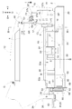
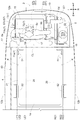
- FIG. 2 is a cross-sectional view taken along the line III-III in FIG.
- FIG. 2 is a cross-sectional view taken along the line IV-IV of FIG.
- It is a perspective view which shows the structure around the radiator.
- It is a top view which shows the structure of a motor and the like.
- It is a figure which shows the structure of the connecting part and the like.
- It is a figure which shows the structure around the opening.
- the tractor A (corresponding to the "electric work vehicle” according to the present invention) has left and right front wheels 10 (corresponding to the “traveling device” according to the present invention) and left and right rear wheels 11 (corresponding to the “traveling device” according to the present invention). (Corresponding to the "traveling device” according to the above), a cover member 12, and a tilling device 13.
- the tractor A includes an airframe frame 2 and a driving unit 3.
- the airframe frame 2 is supported by the left and right front wheels 10 and the left and right rear wheels 11. Further, the tilling device 13 is supported by the rear portion of the machine frame 2.
- the cover member 12 is arranged at the front part of the machine body.
- the driving unit 3 is provided behind the cover member 12.
- the driver unit 3 has a protective frame 30, a driver's seat 31, a steering wheel 32, and a floor 33. The worker can be seated in the driver's seat 31. Then, the operator can perform various driving operations in the driving unit 3.
- the left and right front wheels 10 are steered.
- the worker can put his / her foot on the floor 33 while sitting in the driver's seat 31.
- the tractor A includes a driver unit 3 having a driver seat 31 on which an operator can sit.
- the tractor A includes a traveling battery 4 (corresponding to the "battery” according to the present invention), a motor M, a transmission device T, and a front transmission mechanism FT.
- the cover member 12 is configured to be swingable around the opening / closing axis Q (see FIG. 2) along the left-right direction of the machine body. As a result, the cover member 12 is configured to be openable and closable. Then, when the cover member 12 is in the closed state, the traveling battery 4 is housed in the cover member 12. Then, the traveling battery 4 supplies electric power to the motor M.
- the motor M is arranged below the traveling battery 4. Then, the motor M is driven by the electric power supplied from the traveling battery 4. The driving force of the motor M is transmitted to the transmission device T.
- the transmission device T is located on the rear side of the traveling battery 4 and behind the motor M. Further, the front transmission mechanism FT extends forward from the transmission device T. Then, the transmission device T shifts the driving force received from the motor M and transmits it to the left and right rear wheels 11. Further, the driving force is transmitted from the transmission device T to the left and right front wheels 10 via the front transmission mechanism FT. As a result, the left and right front wheels 10 and the left and right rear wheels 11 are driven.
- the tractor A is arranged below the traveling battery 4 and includes a motor M driven by the electric power supplied from the traveling battery 4. Further, the tractor A includes left and right front wheels 10 and left and right rear wheels 11 driven by a motor M.
- the transmission device T transmits a part of the driving force received from the motor M to the tilling device 13. As a result, the tilling device 13 is driven.
- the tractor A can perform the tilling work by the tilling device 13 while traveling by the left and right front wheels 10 and the left and right rear wheels 11.
- the traveling battery 4 is arranged above the body frame 2.
- a ventilation space S is formed between the machine frame 2 and the traveling battery 4.
- the tractor A includes a traveling battery 4 arranged above the body frame 2.
- the ventilation space S is a space configured to allow ventilation.
- the tractor A is equipped with an inverter 14.
- the inverter 14 is arranged below the traveling battery 4. Further, the inverter 14 is arranged in front of the motor M.
- the inverter 14 is configured to convert the DC power from the traveling battery 4 into AC power and supply it to the motor M.
- the tractor A is arranged below the traveling battery 4 and in front of the motor M, and includes an inverter 14 that converts DC power from the traveling battery 4 into AC power and supplies it to the motor M. ..
- the motor M and the inverter 14 are arranged side by side in the front-rear direction of the machine body.
- the first space S1 is formed between the inverter 14 and the traveling battery 4.
- the first space S1 is included in the ventilation space S. That is, the first space S1 is a space configured to allow ventilation.
- a second space S2 is formed between the motor M and the traveling battery 4.
- the second space S2 is included in the ventilation space S. That is, the second space S2 is a space configured to allow ventilation.
- the motor M is arranged so as to be in contact with the ventilation space S.
- the motor M is in contact with the ventilation space S.
- the airframe frame 2 has left and right main frames 20 and an inverter support portion 21.
- the left and right main frames 20 extend in the front-rear direction of the machine body.
- the tractor A includes a left main frame 20 and a right main frame 20 extending in the front-rear direction of the machine body.
- the motor M is arranged at a position sandwiched between the left and right main frames 20.
- the inverter support portion 21 is provided so as to extend over the left and right main frames 20. Further, the inverter support portion 21 is supported by the left and right main frames 20. The inverter 14 is supported by the inverter support portion 21.
- the inverter 14 is supported by the left main frame 20 and the right main frame 20 via the inverter support portion 21.
- FIG. 3 shows the first left end position LE1, the second left end position LE2, and the third left end position LE3.
- the first left end position LE1 is the left end position of the left main frame 20.
- the second left end position LE2 is the left end position of the inverter 14.
- the third left end position LE3 is the left end position of the inverter support portion 21.
- the second left end position LE2 is located on the left side of the first left end position LE1. That is, the inverter 14 projects to the left side from the left end position of the left main frame 20.
- the third left end position LE3 is located on the left side of the first left end position LE1 and the second left end position LE2. That is, the inverter support portion 21 projects to the left side from the left end position of the left main frame 20.
- FIG. 3 shows the first right end position RE1, the second right end position RE2, and the third right end position RE3.
- the first right end position RE1 is the right end position of the right main frame 20.
- the second right end position RE2 is the right end position of the inverter 14.
- the third right end position RE3 is the right end position of the inverter support portion 21.
- the second right end position RE2 is located on the right side of the first right end position RE1. That is, the inverter 14 projects to the right of the right end position of the right main frame 20.
- the third right end position RE3 is located on the right side of the first right end position RE1 and the second right end position RE2. That is, the inverter support portion 21 projects to the right from the right end position of the right main frame 20.
- the inverter 14 projects to the left from the left end position of the left main frame 20 and to the right from the right end position of the right main frame 20.
- the inverter support portion 21 protrudes to the left side from the left end position of the left main frame 20, and also protrudes to the right side from the right end position of the right main frame 20.
- the tractor A includes left and right first support frames 51, left and right second support frames 52, and battery support 53.
- the left and right first support frames 51 are located on the front side of the left and right second support frames 52. Further, the left and right first support frames 51 and the left and right second support frames 52 are both erected on the inverter support portion 21.
- the left and right first support frames 51 and the left and right second support frames 52 are both erected on the airframe frame 2.
- a plate-shaped support portion 38 and a plate-shaped partition member 56 described later are provided between the motor M and the traveling battery 4.
- the plate-shaped support portion 38 and the plate-shaped partition member 56 are both in a horizontal posture. Further, the plate-shaped partition member 56 is located above the plate-shaped support portion 38.
- the rear support frame 59 is supported by the airframe frame 2. Further, the rear support frame 59 supports the rear end portion of the battery support portion 53 via the plate-shaped support portion 38 and the plate-shaped partition member 56.
- the battery support portion 53 is arranged above the body frame 2.
- the battery support portion 53 is supported by the left and right first support frames 51, the second support frame 52, and the rear support frame 59.
- the traveling battery 4 is supported by the battery support portion 53.
- the tractor A includes a battery support portion 53 that is arranged above the body frame 2 and supports the traveling battery 4.
- the traveling battery 4 is supported by the inverter support portion 21 via the battery support portion 53, the left and right first support frames 51, and the left and right second support frames 52.
- the traveling battery 4 is supported by the inverter support portion 21 via the left and right first support frames 51 erected on the inverter support portion 21. Further, the traveling battery 4 is supported by the inverter support portion 21 via the left and right second support frames 52 erected on the inverter support portion 21.
- the left ventilation opening K is formed by the airframe frame 2, the battery support portion 53, the left first support frame 51, and the left second support frame 52.
- the right ventilation opening K is formed by the airframe frame 2, the battery support portion 53, the right first support frame 51, and the right second support frame 52.
- left and right ventilation openings K are connected to the ventilation space S, respectively.
- the ventilation space S communicates with the left and right ventilation openings K.
- the battery support portion 53 has a plate-shaped bottom plate portion 53a.
- the bottom plate portion 53a is provided in a horizontal posture.
- the bottom plate portion 53a partitions the traveling battery 4 and the inverter 14.
- the tractor A includes a bottom plate portion 53a that partitions the traveling battery 4 and the inverter 14.
- the tractor A includes a first plate-shaped member 54 (corresponding to the “plate-shaped member” according to the present invention) and a second plate-shaped member 55 (“plate-shaped member” according to the present invention). Equivalent to "member").
- the first plate-shaped member 54 and the second plate-shaped member 55 are provided so as to extend over the left and right main frames 20, respectively. Further, the first plate-shaped member 54 is located on the front side of the second plate-shaped member 55. The first plate-shaped member 54 and the second plate-shaped member 55 are both supported by the left and right main frames 20.
- the airframe frame 2 supports the first plate-shaped member 54 and the second plate-shaped member 55.
- Both the first plate-shaped member 54 and the second plate-shaped member 55 are arranged in a horizontal posture below the ventilation space S.
- the cover member 12 has an introduction portion 12a.
- the introduction portion 12a is configured so that the outside air can be introduced into the inside of the cover member 12.
- the introduction portion 12a is provided at the front end portion of the cover member 12.
- the introduction portion 12a is composed of a plurality of small holes.
- the present invention is not limited to this, and the introduction unit 12a may be in any other form.
- the introduction portion 12a may be composed of one hole.
- the introduction unit 12a may include a blower for introducing outside air.
- the cover member 12 has left and right discharge portions 12b.
- the left and right discharge portions 12b are configured so that the air inside the cover member 12 can be discharged to the outside.
- the cover member 12 has left and right discharge portions 12b capable of discharging the air inside the cover member 12 to the outside.
- the left discharge portion 12b is provided on the left side portion of the cover member 12. Further, the right discharge portion 12b is provided on the right side portion of the cover member 12.
- the left discharge unit 12b is located on the left side of the traveling battery 4. Further, the right discharge unit 12b is located on the right side of the traveling battery 4. That is, the left and right discharge portions 12b are located on the lateral sides of the traveling battery 4, respectively.
- the left and right discharge portions 12b are each composed of a plurality of small holes.
- the present invention is not limited to this, and the left and right discharge portions 12b may be in any other form.
- the left and right discharge portions 12b may each be composed of one hole.
- the left and right discharge portions 12b may include a blower for air discharge.
- the tractor A includes a radiator 15 and a water pump 16.
- the radiator 15 is arranged in front of the traveling battery 4.
- the tractor A includes a radiator 15 located in front of the traveling battery 4.
- the radiator 15 and the water pump 16 are included in the cooling water path in the tractor A.
- the cooling water circulates in this cooling water path. Then, the cooling water is cooled by passing through the radiator 15.
- the tractor A includes a water pump 16 that pumps cooling water that passes through the radiator 15.
- the water pump 16 is arranged in front of the motor M and below the inverter 14. Further, the water pump 16 is supported by the first plate-shaped member 54.
- the tractor A is equipped with a cooling fan 17.
- the cooling fan 17 is arranged in front of the traveling battery 4. That is, the cooling fan 17 is located in front of the traveling battery 4.
- the tractor A includes a cover member 12 for accommodating the cooling fan 17 and the traveling battery 4.
- cooling fan 17 is arranged so as to straddle the traveling battery 4 and the ventilation space S in the vertical direction of the machine body. Further, the cooling fan 17 is arranged so as to straddle the traveling battery 4 and the inverter 14 in the vertical direction of the machine body.
- the cooling fan 17 sends cooling air to the rear side.
- the outside air is introduced into the inside of the cover member 12 via the introduction portion 12a and passes through the radiator 15.
- the radiator 15 is cooled.
- the cooling fan 17 cools the radiator 15 and is located in front of the traveling battery 4.
- the cooling fan 17 sends the cooling air to the front part of the traveling battery 4 and the ventilation space S.
- the tractor A is provided with a cooling fan 17 that is arranged in front of the traveling battery 4 and sends cooling air to the traveling battery 4.
- At least a part of the cooling air sent from the cooling fan 17 to the front part of the traveling battery 4 wraps around to the left and right of the traveling battery 4 and is discharged from the left and right discharge units 12b. As a result, the front portion and the lateral portion of the traveling battery 4 are cooled.
- a plate-shaped partition member 56 in a horizontal posture is provided between the battery support portion 53 and the motor M.
- the plate-shaped partition member 56 has a wind direction plate 56a.
- the wind direction plate 56a is formed by bending the front end portion of the plate-shaped partition member 56 downward. Therefore, the wind direction plate 56a is in a vertical posture. As a result, the wind direction plate 56a faces the cooling fan 17.
- the tractor A includes a wind direction plate 56a in a posture facing the cooling fan 17.
- the wind direction plate 56a is arranged below the traveling battery 4 and in front of the second space S2.
- the cooling air flowing through the ventilation space S As a result, of the cooling air flowing through the ventilation space S, the cooling air flowing toward the second space S2 is guided below the wind direction plate 56a by the wind direction plate 56a. As a result, the cooling air tends to go toward the motor M. As a result, the motor M is satisfactorily cooled by the cooling air.
- the tractor A includes a reserve tank 5 for the radiator 15.
- the reserve tank 5 can store cooling water. Further, the reserve tank 5 is arranged on the front side of the traveling battery 4 and on the right side of the radiator 15.
- the tractor A includes an auxiliary battery 18 and a voltage converter 19.
- the auxiliary battery 18 supplies electric power to various auxiliary devices such as the cooling fan 17.
- the voltage converter 19 steps down the electric power from the traveling battery 4 and supplies it to the auxiliary battery 18.
- the tractor A is arranged in front of the traveling battery 4, and includes a voltage converter 19 that steps down the electric power from the traveling battery 4 and supplies it to the auxiliary battery 18.
- the auxiliary battery 18 and the voltage converter 19 are arranged on the front side of the traveling battery 4 and on the right side of the radiator 15. Further, the voltage converter 19 is arranged so that the longitudinal direction of the voltage converter 19 is along the vertical direction of the machine body.
- the voltage converter 19 and the radiator 15 are arranged side by side in a plan view. Further, the radiator 15, the voltage converter 19, and the auxiliary battery 18 are arranged side by side in a plan view.
- the voltage converter 19 is arranged at a position sandwiched between the radiator 15 and the auxiliary battery 18 in a plan view.
- radiator 15, the voltage converter 19, and the reserve tank 5 are arranged side by side in a plan view.
- the voltage converter 19 is arranged at a position sandwiched between the radiator 15 and the reserve tank 5 in a plan view.
- the reserve tank 5 is arranged above the auxiliary battery 18.
- the reserve tank 5 and the auxiliary battery 18 are arranged so as to be arranged in the vertical direction of the machine body.
- the tractor A is provided with an oil cooler CL.
- the hydraulic oil in the tractor A is cooled by passing through the oil cooler CL.
- radiator 15 is supported by a gate-shaped radiator frame 57.
- the radiator frame 57 is arranged so as to surround the radiator 15.
- the tractor A is arranged so as to surround the radiator 15 and includes a gate-shaped radiator frame 57 that supports the radiator 15.
- the radiator frame 57 has a left side plate 57a, a top plate 57b, a right side plate 57c, a first top plate support portion 57d, and a second top plate support portion 57e.
- the left plate 57a is located on the left side of the radiator frame 57.
- the top plate 57b is located above the radiator frame 57.
- the right side plate 57c is located on the right side of the radiator frame 57.
- the left side plate 57a and the right side plate 57c are arranged in a vertical position and arranged side by side. Further, the left side plate 57a and the right side plate 57c are arranged so as to face each other.
- the first top plate support portion 57d is provided so as to extend to the left from the upper end portion of the left side plate 57a. Further, the second top plate support portion 57e is provided so as to extend to the right from the upper end portion of the right side plate 57c. The top plate 57b is placed and supported on the upper surface of the first top plate support portion 57d and the upper surface of the second top plate support portion 57e.
- the voltage converter 19 is attached to the radiator frame 57. More specifically, the voltage converter 19 is attached to the right side of the right side plate 57c.
- the tractor A includes a first hose 6a, a second hose 6b, a water supply unit 6c, and a third hose 6d.
- the first hose 6a, the second hose 6b, the water supply unit 6c, and the third hose 6d are included in the cooling water path in the tractor A.
- One end of the first hose 6a is connected to the radiator 15.
- the other end of the first hose 6a is connected to the water supply portion 6c.
- the tractor A includes a first hose 6a connected to the radiator 15.
- One end of the second hose 6b is connected to the water supply unit 6c.
- the other end of the second hose 6b is connected to the voltage converter 19.
- the third hose 6d is connected to the voltage converter 19.
- the worker can supply cooling water to the water supply unit 6c. Further, the cooling water flows in the order of the third hose 6d, the voltage converter 19, the second hose 6b, the water supply unit 6c, the first hose 6a, and the radiator 15.
- the tractor A includes a support portion 7 and a cover support member 58.
- the support portion 7 is supported by the radiator frame 57.
- the support portion 7 extends upward from the upper portion of the radiator frame 57.
- the tractor A includes a support portion 7 extending upward from the upper portion of the radiator frame 57.
- the cover support member 58 is a rod-shaped member. Then, one end of the cover support member 58 is connected to the upper end of the support portion 7 in a state where it can swing up and down around the swing shaft core P along the front-rear direction of the machine body.
- the cover support member 58 can support the cover member 12 in the open state.
- the tractor A is provided with a cover support member 58 that is connected to the upper end portion of the support portion 7 and can support the cover member 12 in the open state.
- the voltage converter 19 When the cover member 12 is in the closed state, the voltage converter 19, the first hose 6a, the radiator frame 57, the reserve tank 5, and the auxiliary battery 18 are housed in the cover member 12.
- the tractor A accommodates the voltage converter 19, the radiator 15, the first hose 6a, and the radiator frame 57, and includes a cover member 12 that can be opened and closed.
- the support portion 7 has a first portion 71, a second portion 72, and a third portion 73.
- the first part 71 extends upward from the upper part of the radiator frame 57.
- the lower end of the first portion 71 is connected to the upper portion of the radiator frame 57.
- the second part 72 extends from the middle part in the vertical direction of the machine body in the first part 71 to the front side.
- the second part 72 is in a horizontal posture.
- the third part 73 extends downward from the front end portion of the second part 72 and is connected to the upper part of the radiator frame 57.
- the third portion 73 is in a forward-down posture.
- the rear end of the third site 73 is connected to the front end of the second site 72.
- the front end portion of the third portion 73 is connected to the upper portion of the radiator frame 57.
- the support portion 7 is provided from the first portion 71 extending upward from the upper part of the radiator frame 57, the second portion 72 extending from the middle portion in the vertical direction of the machine body to the front side in the first portion 71, and the front end portion of the second portion 72. It has a third portion 73 that extends downward and connects to the upper part of the radiator frame 57.
- the first hose 6a is arranged so as to pass through the region AR surrounded by the first portion 71, the second portion 72, and the third portion 73.
- the first portion 71 has a support stay 71a and a vertical fixing portion 71b.
- the support stay 71a has a long plate shape and extends in the vertical direction of the machine body in a posture along the left side plate 57a. Further, the lower end portion of the support stay 71a is bolted to the rear end portion at the upper end portion of the left side plate 57a.
- the vertical fixing portion 71b has a long plate shape and extends in the vertical direction of the machine body. In the vertical direction of the machine body, the length of the vertical fixing portion 71b is shorter than the length of the support stay 71a.
- the vertical fixing portion 71b is fixed to the left surface of the support stay 71a in a posture perpendicular to the support stay 71a.
- the vertical fixing portion 71b, the second portion 72, and the third portion 73 are integrally formed.
- the above-mentioned region AR is surrounded by the support stay 71a, the second portion 72, and the third portion 73.
- a horizontal support plate SP is provided at the front of the tractor A.
- the radiator 15, the cooling fan 17, the auxiliary battery 18, the voltage converter 19, the radiator frame 57, and the oil cooler CL are supported by the support plate SP.
- the tractor A includes a hydraulic pump 60.
- the hydraulic pump 60 supplies hydraulic oil to the operating mechanism that operates the tilling device 13. Then, by controlling the supply of hydraulic oil, the tilling device 13 can be operated.
- the tractor A has an elevating mechanism 36 which is an operating mechanism of the working device.
- the hydraulic pump 60 supplies hydraulic oil to the elevating mechanism 36.
- the elevating mechanism 36 operates.
- the tilling device 13 moves up and down by the operation of the raising and lowering mechanism 36.
- the drive unit of the tilling portion 13a of the tilling device 13 is connected to the PTO shaft 37 of the tractor A, and the tilling work can be performed by the power thereof.
- the hydraulic pump 60 is arranged at a position adjacent to the motor M.
- the motor M is supported by the front support frame 50 and the rear support frame 59.
- the front support frame 50 is provided so as to extend over the left and right main frames 20. Further, the front support frame 50 is fixed to the lower parts of the left and right main frames 20. Further, the front support frame 50 is located below the front portion of the motor M. The front support frame 50 supports the front portion of the motor M.
- the rear support frame 59 is provided so as to extend over the left and right main frames 20. Further, the rear support frame 59 is in contact with the rear end portion of the motor M. The rear support frame 59 supports the rear portion of the motor M.
- the hydraulic pump 60 is attached to the rear support frame 59 from the front side. As a result, the hydraulic pump 60 is supported by the rear support frame 59.
- the motor M and the hydraulic pump 60 are supported by a common rear support frame 59.
- a first rotating body 64 is attached to the motor output shaft 61, which is the output shaft of the motor M.
- the first rotating body 64 rotates integrally with the motor output shaft 61.
- the tractor A is attached to the motor output shaft 61 and includes a first rotating body 64 that rotates integrally with the motor output shaft 61.
- a second rotating body 65 is attached to the pump input shaft 62, which is the input shaft of the hydraulic pump 60.
- the second rotating body 65 rotates integrally with the pump input shaft 62.
- the tractor A is attached to the pump input shaft 62, which is the input shaft of the hydraulic pump 60, and includes a second rotating body 65 that rotates integrally with the pump input shaft 62.
- the endless rotating body 66 is wound around the first rotating body 64 and the second rotating body 65.
- the tractor A includes an endless rotating body 66 wound around the first rotating body 64 and the second rotating body 65.
- the endless rotating body 66 is a belt.
- the present invention is not limited to this, and the endless rotating body 66 does not have to be a belt.
- the endless rotating body 66 may be a chain.
- the driving force of the motor M is transmitted to the hydraulic pump 60 via the motor output shaft 61, the first rotating body 64, the endless rotating body 66, the second rotating body 65, and the pump input shaft 62. As a result, the hydraulic pump 60 is driven.
- the tractor A includes a hydraulic pump 60 that is driven by the motor M and supplies hydraulic oil to the tilling device 13.
- the transmission input shaft 63 which is the input shaft of the transmission device T, and the motor output shaft 61 are connected by the connecting portion 8. As a result, the transmission input shaft 63 rotates integrally with the motor output shaft 61.
- both the motor output shaft 61 and the transmission input shaft 63 are formed in a tubular shape and extend in the front-rear direction of the machine body.
- the connecting portion 8 has a connecting shaft 81 and a pin 82.
- the connecting shaft 81 extends in the front-rear direction of the machine body.
- the front end portion of the connecting shaft 81 is inserted into the motor output shaft 61 and spline-fitted to the motor output shaft 61.
- the rear end portion of the connecting shaft 81 is inserted into the transmission input shaft 63 and spline-fitted to the transmission input shaft 63.
- a pin hole 63a is formed in the transmission input shaft 63. Then, the pin 82 is inserted into the pin hole 63a. In this state, the pin 82 is located behind the connecting shaft 81. The pin 82 prevents the connecting shaft 81 from sliding backward.
- the tractor A includes a connecting portion 8 that connects the transmission input shaft 63 and the motor output shaft 61 so that the transmission input shaft 63 and the motor output shaft 61 cannot rotate relative to each other.
- the connecting portion 8 is configured so that the state can be changed between the connected state and the unconnected state.
- the connected state is a state in which the transmission input shaft 63 and the motor output shaft 61 are connected.
- the unconnected state is a state in which the transmission input shaft 63 and the motor output shaft 61 are not connected.
- the connecting portion 8 In the state shown on the left side of the paper in FIG. 7, the connecting portion 8 is in a connected state. At this time, as described above, the transmission input shaft 63 and the motor output shaft 61 cannot rotate relative to each other. Therefore, the transmission input shaft 63 rotates integrally with the motor output shaft 61.
- the connecting portion 8 is in the state shown on the right side of the paper in FIG. In the state shown on the right side of the paper surface of FIG. 7, the connecting portion 8 is in a non-connected state.
- the connecting shaft 81 is separated from the motor output shaft 61.
- a gap G is formed between the front end of the connecting shaft 81 and the rear end of the motor output shaft 61.
- the gap G is located between the front end of the transmission input shaft 63 and the rear end of the motor output shaft 61.
- the width of the gap G is larger than the width of the endless rotating body 66.
- a gap G through which the removed endless rotating body 66 can pass is formed between the front end of the transmission input shaft 63 and the rear end of the motor output shaft 61.
- the first rotating body 64 has a first divided body 67 and a second divided body 68.
- the first division body 67 is located in front of the second division body 68. Then, as shown on the left side of the paper surface of FIG. 7, the front side surface of the second divided body 68 is in contact with the rear side surface of the first divided body 67.
- the first divided body 67 has a winding portion 67a and a flange portion 67b.
- the winding portion 67a is configured so that the endless rotating body 66 can be wound.
- the flange portion 67b is located at the front end portion of the first partition body 67. The flange portion 67b protrudes in the radial direction.
- the second divided body 68 is configured in a disk shape. Then, the second divided body 68 is fixed to the rear end of the winding portion 67a by a plurality of fixing bolts 69.
- the outer diameter of the second divided body 68 is the same as the outer diameter of the flange portion 67b.
- the second divided body 68 can be removed by removing the plurality of fixing bolts 69. Then, in the state where the second divided body 68 is removed, the endless rotating body 66 can be easily removed from the first rotating body 64 by moving the endless rotating body 66 to the rear side.
- the operator can easily remove the endless rotating body 66 from the tractor A by removing the endless rotating body 66 from the first rotating body 64 and passing it through the gap G. Can be done.
- the endless rotating body 66 when the endless rotating body 66 is attached to the tractor A, the operator passes the endless rotating body 66 through the gap G and winds it around the winding portion 67a, and then the state shown on the left side of the paper surface of FIG. And. As a result, the endless rotating body 66 can be easily attached to the tractor A.
- the tractor A includes a tension adjusting mechanism 9.
- the tension adjusting mechanism 9 has a tension ring 91, a long linking member 92, and an adjusting portion 93.
- the tension wheel 91 abuts on the endless rotating body 66 and applies tension to the endless rotating body 66. Further, the tension wheel 91 is supported by the airframe frame 2 via the linking member 92.
- the adjustment unit 93 is configured to be artificially operable. By artificially operating the adjusting unit 93, the linking member 92 moves in the longitudinal direction of the linking member 92. Then, as the linking member 92 moves, the tension ring 91 moves in the longitudinal direction of the linking member 92. As a result, the tension of the endless rotating body 66 changes.
- the tension adjusting mechanism 9 is configured so that the tension of the endless rotating body 66 can be adjusted by an artificial operation.
- the tractor A includes a tension adjusting mechanism 9 capable of adjusting the tension of the endless rotating body 66 by an artificial operation.
- the operation unit 3 has a wall portion 34 and an opening cover member 35.
- the wall portion 34 is provided in a state of partitioning between the driver's seat 31, the endless rotating body 66, and the tension adjusting mechanism 9. Further, in the wall portion 34, an opening 34a is formed in the vicinity of the tension adjusting mechanism 9. The opening 34a is located near the front end portion of the floor 33.
- the opening cover member 35 is provided so as to close the opening 34a.
- the opening cover member 35 is removable. By removing the opening cover member 35, the opening 34a is opened. Further, by attaching the opening cover member 35, the opening 34a is closed.
- the opening cover member 35 is attached to the wall portion 34 by the bolt b1. Then, the opening cover member 35 can be removed by removing the bolt b1. Although only one bolt b1 is shown in FIG. 8, the number of bolts b1 may be any number of one or more.
- the driver unit 3 has a wall unit 34 that partitions the driver's seat 31, the endless rotating body 66, and the tension adjusting mechanism 9. Further, the driving unit 3 has an opening cover member 35 capable of opening and closing the opening 34a.
- the opening cover member 35 may be attached to the wall portion 34 without using the bolt b1.
- the opening cover member 35 may be attached to the wall portion 34 by forming a convex portion on the opening cover member 35 and forming a concave portion on the wall portion 34 and fitting the convex portion into the concave portion. ..
- the operator can easily access the adjusting unit 93 through the opening 34a by removing the opening cover member 35.
- the cooling air from the cooling fan 17 flows in a state of straddling the traveling battery 4 and the ventilation space S in the vertical direction of the machine body. That is, a part of the cooling air from the cooling fan 17 goes to the traveling battery 4, and another part goes to the ventilation space S.
- the traveling battery 4 is cooled by the cooling air toward the traveling battery 4. Further, the cooling air toward the ventilation space S flows below the traveling battery 4. As a result, hot air is less likely to be trapped between the machine frame 2 and the traveling battery 4.
- the number of the first support frames 51 provided may be one or three or more.
- the number of the second support frames 52 provided may be one or three or more.
- the number of ventilation openings K provided may be one or three or more.
- the number of discharge units 12b provided may be one or three or more.
- the cover member 12 is provided with one vent, and this vent may also be used as the introduction portion 12a and the discharge portion 12b.
- the second part 72 does not have to be in a horizontal posture.
- the second portion 72 may be in a forward-up posture or a forward-down posture.
- the third part 73 does not have to be in a forward-down posture.
- the third portion 73 may be in a vertical posture, or may be in a posture extending backward and downward from the front end portion of the second portion 72.
- the connecting shaft 81 may be slidable forward. In this case, a gap G may be formed between the rear end of the connecting shaft 81 and the front end of the transmission input shaft 63.
- the front end of the connecting shaft 81 may be configured to move to the rear side of the front end of the transmission input shaft 63 by sliding the connecting shaft 81 backward.
- a gap G may be formed between the rear end of the motor output shaft 61 and the front end of the transmission input shaft 63.
- the second divided body 68 may be fixed to the rear end of the winding portion 67a by a single fixing bolt 69.
- the second divided body 68 may be fixed to the rear end of the winding portion 67a without using the fixing bolt 69.
- a convex portion is formed in the first divided body 67
- a concave portion is formed in the second divided body 68
- the convex portion is fitted into the concave portion so that the second divided body 68 is after the winding portion 67a. It may be fixed to the edge.
- the outer diameter of the second divided body 68 may be different from the outer diameter of the flange portion 67b.
- the tractor A may be equipped with an engine and configured in a hybrid manner.
- the wind direction plate 56a may not be provided.
- the plate-shaped partition member 56 may not be provided.
- the second space S2 may not be formed between the motor M and the traveling battery 4.
- the second space S2 does not have to be included in the ventilation space S. That is, the second space S2 and the ventilation space S may be partitioned.
- the first space S1 may not be formed between the inverter 14 and the traveling battery 4.
- the first space S1 does not have to be included in the ventilation space S. That is, the first space S1 and the ventilation space S may be partitioned.
- the cover member 12 may not be provided.
- the discharge unit 12b may not be provided.
- the introduction unit 12a may not be provided.
- the discharge unit 12b may be provided at a position other than the lateral side of the traveling battery 4.
- the discharge unit 12b may be provided at a position rearward from the traveling battery 4.
- the first plate-shaped member 54 may not be provided.
- the second plate-shaped member 55 may not be provided.
- the first plate-shaped member 54 does not have to be in a horizontal posture.
- the first plate-shaped member 54 may be inclined forward or backward.
- the second plate-shaped member 55 does not have to be in a horizontal posture.
- the second plate-shaped member 55 may be inclined forward or backward.
- the first support frame 51 does not have to be erected on the airframe frame 2.
- the second support frame 52 does not have to be erected on the airframe frame 2.
- the first support frame 51 may not be provided.
- the second support frame 52 may not be provided.
- the first hose 6a may be arranged so as not to pass through the region AR surrounded by the first part 71, the second part 72, and the third part 73.
- the first hose 6a may be arranged so as to pass in front of the third portion 73.
- the support portion 7 does not have to have the second portion 72 and the third portion 73.
- the cover support member 58 may not be provided.
- the support portion 7 may not be provided.
- Part or all of the first hose 6a, the second hose 6b, the water supply unit 6c, and the third hose 6d may not be provided.
- the voltage converter 19 may be arranged so that the longitudinal direction of the voltage converter 19 is along the front-rear direction of the machine body, or the longitudinal direction of the voltage converter 19 may be arranged along the left-right direction of the machine body. ..
- the voltage converter 19 does not have to be attached to the radiator frame 57.
- the radiator frame 57 may not be provided.
- the reserve tank 5 and the auxiliary battery 18 do not have to be arranged side by side in the vertical direction of the machine body.
- the reserve tank 5 and the auxiliary battery 18 may be arranged side by side in the left-right direction of the machine body.
- the radiator 15, the voltage converter 19, and the reserve tank 5 do not have to be arranged side by side in a plan view.
- the reserve tank 5 may be arranged above the voltage converter 19.
- the radiator 15, the voltage converter 19, and the auxiliary battery 18 do not have to be arranged side by side in a plan view.
- the auxiliary battery 18 may be arranged above the voltage converter 19.
- the cooling fan 17 may be configured to send cooling air in a direction other than the rear side.
- the cooling fan 17 may be configured to send cooling air to the front side.
- the cooling fan 17 may be arranged above the inverter 14 or below the inverter 14.
- the bottom plate portion 53a may not be provided.
- the inverter support portion 21 may be located on the right side of the left end position of the left main frame 20.
- the inverter support portion 21 may be located on the left side of the right end position of the right main frame 20.
- the inverter support portion 21 may not be provided. In this case, the inverter 14 may be directly supported by the left main frame 20 and the right main frame 20.
- the inverter 14 may be located on the right side of the left end position of the left main frame 20.
- the inverter 14 may be located on the left side of the right end position of the right main frame 20.
- the airframe frame 2 does not have to have the left and right main frames 20.
- the airframe frame 2 may be composed of a single frame member.
- the water pump 16 may be arranged at a position other than the front of the motor M.
- the water pump 16 may be arranged behind the motor M.
- the water pump 16 may be arranged above the inverter 14.
- the motor M may be arranged at a position other than the position sandwiched between the left and right main frames 20.
- the motor M may be arranged above the left and right main frames 20.
- the hydraulic pump 60 does not have to be supported by the rear support frame 59. That is, the motor M and the hydraulic pump 60 do not have to be supported by the common rear support frame 59.
- the opening cover member 35 may be configured so that the opening 34a cannot be opened and closed.
- the opening cover member 35 may be configured so that it cannot be removed.
- the opening 34a may not be formed in the wall portion 34.
- the wall portion 34 may not be provided.
- the opening cover member 35 may not be provided.
- the tension adjusting mechanism 9 may not be provided.
- the connecting portion 8 may be configured so that the state cannot be changed from the connected state to the unconnected state.
- the connecting portion 8 may not be provided.
- the first rotating body 64 and the second rotating body 65 are both gears and may mesh with each other. In this case, the endless rotating body 66 may not be provided.
- the transmission input shaft 63 may not rotate integrally with the motor output shaft 61.
- the transmission input shaft 63 and the motor output shaft 61 may be linked via a plurality of gears.
- the transmission device T may be arranged at a position other than the rear of the motor M.
- the transmission device T may be arranged in front of the motor M.
- various devices such as a fertilizer spraying device, a chemical spraying device, a sowing device, and a harvesting device, and a working device such as a loader and an excavator may be provided.
- the wind direction plate 56a does not have to be in a vertical posture.
- the wind direction plate 56a may be inclined forward or backward.
- the motor M may be arranged at a position other than below the traveling battery 4.
- the motor M may be arranged above the traveling battery 4.
- the inverter 14 may be arranged at a position other than below the traveling battery 4.
- the inverter 14 may be arranged above the traveling battery 4.
- the voltage converter 19 and the radiator 15 do not have to be arranged side by side in a plan view.
- the voltage converter 19 may be located above the radiator 15.
- the radiator 15 may be arranged behind the traveling battery 4.
- the voltage converter 19 may be arranged behind the traveling battery 4.
- the voltage converter 19 may not be provided.
- the auxiliary battery 18 may not be provided.
- the motor M and the inverter 14 may be arranged side by side in the left-right direction of the machine body, or may be arranged in a state of being lined up in the vertical direction of the machine body.
- the transmission device T may be arranged in front of the traveling battery 4.
- the hydraulic pump 60 may be arranged at a position relatively far from the motor M.
- the hydraulic pump 60 may be driven by a power source other than the motor M.
- the present invention can be used not only for tractors but also for various electric work vehicles such as combine harvesters, rice transplanters, and construction work machines.
- Airframe frame 4 Driving battery (battery) 10 Front wheels (traveling device) 11 Rear wheel (traveling device) 12 Cover member 12b Discharge part 14 Inverter 17 Cooling fan 51 First support frame 52 Second support frame 53 Battery support part 54 First plate-like member (plate-like member) 55 Second plate-shaped member (plate-shaped member) 56a Wind direction plate K Ventilation opening M Motor S Ventilation space S1 First space S2 Second space
Landscapes
- Engineering & Computer Science (AREA)
- Transportation (AREA)
- Mechanical Engineering (AREA)
- Chemical & Material Sciences (AREA)
- Combustion & Propulsion (AREA)
- Power Engineering (AREA)
- Sustainable Development (AREA)
- Sustainable Energy (AREA)
- Life Sciences & Earth Sciences (AREA)
- Cooling, Air Intake And Gas Exhaust, And Fuel Tank Arrangements In Propulsion Units (AREA)
- Arrangement Or Mounting Of Propulsion Units For Vehicles (AREA)
- Electric Propulsion And Braking For Vehicles (AREA)
- Motor Or Generator Cooling System (AREA)
Abstract
電動作業車は、機体フレーム2よりも上側に配置されたバッテリ4と、バッテリ4から供給される電力により駆動するモータMと、モータMにより駆動される走行装置と、バッテリ4の前方に配置されると共にバッテリ4へ冷却風を送る冷却ファン17と、を備え、機体フレーム2とバッテリ4との間に通風空間Sが形成されており、冷却ファン17は、機体上下方向において、バッテリ4と通風空間Sとにまたがる状態で配置されている。
Description
本発明は、バッテリと、バッテリから供給される電力により駆動するモータと、モータにより駆動される走行装置と、を備える電動作業車に関する。
特許文献1に記載の作業車(特許文献1では「トラクター」)は、エンジンと、エンジンにより駆動される走行装置(特許文献1では「前車輪」及び「後車輪」)と、を備えている。
特許文献1に記載の作業車において、エンジンに代えてバッテリ及びモータを設けることが考えられる。これにより、排気ガスを排出することなく走行することができる。
しかしながら、バッテリから、比較的多くの熱が発生しがちである。そして、バッテリの周囲に熱気がこもると、熱によってバッテリの劣化が大きく進行してしまう事態が想定される。
本発明の目的は、バッテリが効果的に冷却される電動作業車を提供することである。
本発明の特徴は、機体フレームよりも上側に配置されたバッテリと、前記バッテリから供給される電力により駆動するモータと、前記モータにより駆動される走行装置と、前記バッテリの前方に配置されると共に前記バッテリへ冷却風を送る冷却ファンと、を備え、前記機体フレームと前記バッテリとの間に通風空間が形成されており、前記冷却ファンは、機体上下方向において、前記バッテリと前記通風空間とにまたがる状態で配置されていることにある。
本発明であれば、冷却ファンからの冷却風は、機体上下方向においてバッテリと通風空間とにまたがる状態で流れる。即ち、冷却ファンからの冷却風のうちの一部はバッテリへ向かい、別の一部は通風空間へ向かう。
そして、バッテリへ向かう冷却風によって、バッテリが冷却される。また、通風空間へ向かう冷却風は、バッテリの下方を流れる。これにより、機体フレームとバッテリとの間に熱気がこもりにくい。
従って、本発明であれば、バッテリが効果的に冷却される電動作業車を実現できる。
さらに、本発明において、前記機体フレームよりも上側に配置されると共に前記バッテリを支持するバッテリ支持部を備え、前記バッテリ支持部は、第1支持フレーム及び第2支持フレームによって支持されており、前記第1支持フレーム及び前記第2支持フレームは、何れも、前記機体フレームに立設されており、前記機体フレームと、前記バッテリ支持部と、前記第1支持フレームと、前記第2支持フレームと、によって通風開口が形成されており、前記通風空間は、前記通風開口に連通していると好適である。
この構成によれば、バッテリ支持部は、機体フレームから上側に離間した状態で配置される。そのため、バッテリも、機体フレームから上側に離間した状態で配置される。これにより、機体フレームとバッテリとの間に、通風空間が確実に形成される。
しかも、この構成によれば、通風空間を流れる冷却風は、通風開口を介して通風空間の外部へ通り抜ける。これにより、冷却風が通風空間を良好に通り抜ける電動作業車を実現できる。
さらに、本発明において、前記冷却ファン及び前記バッテリを収容するカバー部材を備え、前記カバー部材は、前記カバー部材の内側の空気を外部へ排出可能な排出部を有しており、前記排出部は、前記バッテリの横側方に位置しており、前記機体フレームは、板状部材を支持しており、前記板状部材は、前記通風空間の下方に、水平姿勢で配置されていると好適である。
この構成によれば、冷却ファンからバッテリの前部に供給された冷却風のうちの少なくとも一部が、バッテリの横側方へ回り込み、排出部から排出される。これにより、バッテリの前部及び横側部が効果的に冷却される。
しかも、この構成によれば、通風空間の下方に板状部材が設けられているため、冷却風が通風空間から下方へ抜けにくい。これにより、通風空間を流れる冷却風が、通風空間の後部へ到達する前に下方へ抜けてしまう事態を回避しやすい。
従って、この構成によれば、冷却風が通風空間の後部まで到達しやすい。これにより、バッテリの下部が効果的に冷却されやすい。
さらに、本発明において、前記バッテリからの直流電力を交流電力に変換して前記モータへ供給するインバータを備え、前記インバータは、前記バッテリの下方に配置されており、前記インバータと前記バッテリとの間に第1空間が形成されており、前記第1空間は、前記通風空間に含まれていると好適である。
この構成によれば、冷却ファンから通風空間へ供給された冷却風によって、インバータを冷却することが可能となる。
ここで、インバータとバッテリとの間に空間が形成されていない場合、冷却ファンから通風空間へ供給された冷却風は、インバータとバッテリとの間を通ることができない。その結果、バッテリの下部が冷却されにくくなる事態が想定される。
これに対して、上記の構成によれば、インバータとバッテリとの間に第1空間が形成されており、第1空間は通風空間に含まれている。そのため、冷却風がインバータとバッテリとの間を通過する構成を実現できる。これにより、バッテリの下部が冷却されにくくなる事態を回避しやすい。
さらに、本発明において、前記モータは、前記バッテリの下方に配置されており、前記モータと前記バッテリとの間に第2空間が形成されており、前記第2空間は、前記通風空間に含まれていると好適である。
この構成によれば、冷却ファンから通風空間へ供給された冷却風によって、モータを冷却することが可能となる。
ここで、モータとバッテリとの間に空間が形成されていない場合、冷却ファンから通風空間へ供給された冷却風は、モータとバッテリとの間を通ることができない。その結果、バッテリの下部が冷却されにくくなる事態が想定される。
これに対して、上記の構成によれば、モータとバッテリとの間に第2空間が形成されており、第2空間は通風空間に含まれている。そのため、冷却風がモータとバッテリとの間を通過する構成を実現できる。これにより、バッテリの下部が冷却されにくくなる事態を回避しやすい。
さらに、本発明において、前記モータは、前記通風空間に接しており、前記冷却ファンに対向する姿勢の風向板を備え、前記風向板は、前記バッテリの下方において、前記第2空間の前方に配置されていると好適である。
この構成によれば、通風空間を流れる冷却風のうち、第2空間へ向かって流れる冷却風は、風向板まで到達すると、風向板によって下側へガイドされる。その結果、冷却風はモータへ向かいやすくなる。これにより、モータを良好に冷却することが可能となる。
本発明を実施するための形態について、図面に基づき説明する。尚、以下の説明においては、図1から図3、図6、図7に示す矢印Fの方向を「前」、矢印Bの方向を「後」として、図3、図4、図6に示す矢印Lの方向を「左」、矢印Rの方向を「右」とする。また、図1、図2、図4に示す矢印Uの方向を「上」、矢印Dの方向を「下」とする。
〔トラクタの全体構成〕
図1に示すように、トラクタA(本発明に係る「電動作業車」に相当)は、左右の前車輪10(本発明に係る「走行装置」に相当)、左右の後車輪11(本発明に係る「走行装置」に相当)、カバー部材12、耕耘装置13を備えている。
図1に示すように、トラクタA(本発明に係る「電動作業車」に相当)は、左右の前車輪10(本発明に係る「走行装置」に相当)、左右の後車輪11(本発明に係る「走行装置」に相当)、カバー部材12、耕耘装置13を備えている。
また、トラクタAは、機体フレーム2及び運転部3を備えている。
機体フレーム2は、左右の前車輪10及び左右の後車輪11に支持されている。また、耕耘装置13は、機体フレーム2の後部に支持されている。
カバー部材12は、機体前部に配置されている。そして、運転部3は、カバー部材12の後方に設けられている。
運転部3は、保護フレーム30、運転座席31、ステアリングホイール32、フロア33を有している。作業者は、運転座席31に着座可能である。そして、作業者は、運転部3において、各種の運転操作を行うことができる。
ステアリングホイール32の操作によって、左右の前車輪10は操向操作される。また、作業者は、運転座席31に着座した状態で、フロア33に足を置くことができる。
即ち、トラクタAは、作業者が着座可能な運転座席31を有する運転部3を備えている。
また、トラクタAは、走行用バッテリ4(本発明に係る「バッテリ」に相当)、モータM、伝動装置T、前伝動機構FTを備えている。
カバー部材12は、機体左右方向に沿う開閉軸芯Q(図2参照)周りに揺動可能に構成されている。これにより、カバー部材12は、開閉可能に構成されている。そして、カバー部材12が閉状態であるとき、走行用バッテリ4は、カバー部材12に収容されている。そして、走行用バッテリ4は、モータMへ電力を供給する。
モータMは、走行用バッテリ4の下方に配置されている。そして、モータMは、走行用バッテリ4から供給される電力により駆動する。モータMの駆動力は、伝動装置Tへ伝達される。
伝動装置Tは、走行用バッテリ4よりも後側であり、且つ、モータMの後方に配置されている。また、前伝動機構FTは、伝動装置Tから前側に延びている。そして、伝動装置Tは、モータMから受け取った駆動力を変速し、左右の後車輪11に伝達する。また、駆動力は、伝動装置Tから、前伝動機構FTを介して、左右の前車輪10にも伝達される。
これにより、左右の前車輪10及び左右の後車輪11は駆動される。
これにより、左右の前車輪10及び左右の後車輪11は駆動される。
即ち、トラクタAは、走行用バッテリ4の下方に配置されると共に、走行用バッテリ4から供給される電力により駆動するモータMを備えている。また、トラクタAは、モータMにより駆動される左右の前車輪10及び左右の後車輪11を備えている。
また、伝動装置Tは、モータMから受け取った駆動力の一部を、耕耘装置13に伝達する。これにより、耕耘装置13が駆動される。
以上の構成により、トラクタAは、左右の前車輪10及び左右の後車輪11によって走行しながら、耕耘装置13によって耕耘作業を行うことができる。
〔走行用バッテリ、モータ、インバータの配置〕
図2から図4に示すように、走行用バッテリ4は、機体フレーム2よりも上側に配置されている。そして、機体フレーム2と走行用バッテリ4との間に通風空間Sが形成されている。
図2から図4に示すように、走行用バッテリ4は、機体フレーム2よりも上側に配置されている。そして、機体フレーム2と走行用バッテリ4との間に通風空間Sが形成されている。
即ち、トラクタAは、機体フレーム2よりも上側に配置された走行用バッテリ4を備えている。
尚、通風空間Sは、通風可能に構成された空間である。
また、トラクタAは、インバータ14を備えている。インバータ14は、走行用バッテリ4の下方に配置されている。また、インバータ14は、モータMよりも前側に配置されている。
そして、インバータ14は、走行用バッテリ4からの直流電力を交流電力に変換してモータMへ供給するように構成されている。
即ち、トラクタAは、走行用バッテリ4の下方且つモータMよりも前側に配置されると共に、走行用バッテリ4からの直流電力を交流電力に変換してモータMへ供給するインバータ14を備えている。
モータMとインバータ14とは、機体前後方向に並ぶ状態で配置されている。
また、インバータ14と走行用バッテリ4との間に第1空間S1が形成されている。第1空間S1は、通風空間Sに含まれている。即ち、第1空間S1は、通風可能に構成された空間である。
また、モータMと走行用バッテリ4との間に第2空間S2が形成されている。第2空間S2は、通風空間Sに含まれている。即ち、第2空間S2は、通風可能に構成された空間である。
そして、モータMは、通風空間Sに接するように配置されている。
即ち、モータMは、通風空間Sに接している。
また、機体フレーム2は、左右の主フレーム20、及び、インバータ支持部21を有している。左右の主フレーム20は、機体前後方向に延びている。
即ち、トラクタAは、機体前後方向に延びる左の主フレーム20及び右の主フレーム20を備えている。
モータMは、左右の主フレーム20の間に挟まれる位置に配置されている。
インバータ支持部21は、左右の主フレーム20に亘る状態で設けられている。また、インバータ支持部21は、左右の主フレーム20に支持されている。そして、インバータ14は、インバータ支持部21に支持されている。
即ち、インバータ14は、インバータ支持部21を介して左の主フレーム20及び右の主フレーム20に支持されている。
図3には、第1左端位置LE1、第2左端位置LE2、第3左端位置LE3が示されている。第1左端位置LE1は、左の主フレーム20の左端位置である。第2左端位置LE2は、インバータ14の左端位置である。第3左端位置LE3は、インバータ支持部21の左端位置である。
図3に示すように、第2左端位置LE2は、第1左端位置LE1よりも左側に位置している。即ち、インバータ14は、左の主フレーム20の左端位置よりも左側へ突出している。
また、第3左端位置LE3は、第1左端位置LE1及び第2左端位置LE2よりも左側に位置している。即ち、インバータ支持部21は、左の主フレーム20の左端位置よりも左側へ突出している。
また、図3には、第1右端位置RE1、第2右端位置RE2、第3右端位置RE3が示されている。第1右端位置RE1は、右の主フレーム20の右端位置である。第2右端位置RE2は、インバータ14の右端位置である。第3右端位置RE3は、インバータ支持部21の右端位置である。
図3に示すように、第2右端位置RE2は、第1右端位置RE1よりも右側に位置している。即ち、インバータ14は、右の主フレーム20の右端位置よりも右側へ突出している。
また、第3右端位置RE3は、第1右端位置RE1及び第2右端位置RE2よりも右側に位置している。即ち、インバータ支持部21は、右の主フレーム20の右端位置よりも右側へ突出している。
即ち、インバータ14は、左の主フレーム20の左端位置よりも左側へ突出しており、且つ、右の主フレーム20の右端位置よりも右側へ突出している。
また、インバータ支持部21は、左の主フレーム20の左端位置よりも左側へ突出しており、且つ、右の主フレーム20の右端位置よりも右側へ突出している。
図2から図4に示すように、トラクタAは、左右の第1支持フレーム51、左右の第2支持フレーム52、バッテリ支持部53を備えている。
左右の第1支持フレーム51は、左右の第2支持フレーム52よりも前側に位置している。また、左右の第1支持フレーム51、及び、左右の第2支持フレーム52は、何れも、インバータ支持部21に立設されている。
即ち、左右の第1支持フレーム51、及び、左右の第2支持フレーム52は、何れも、機体フレーム2に立設されている。
また、モータMと走行用バッテリ4との間に、板状支持部38及び後述の板状仕切部材56が設けられている。板状支持部38及び板状仕切部材56は、何れも水平姿勢である。また、板状仕切部材56は、板状支持部38の上方に位置している。
また、後部支持フレーム59は、機体フレーム2に支持されている。また、後部支持フレーム59は、板状支持部38及び板状仕切部材56を介して、バッテリ支持部53の後端部を支持している。
バッテリ支持部53は、機体フレーム2よりも上側に配置されている。そして、バッテリ支持部53は、左右の第1支持フレーム51、第2支持フレーム52、後部支持フレーム59によって支持されている。そして、走行用バッテリ4は、バッテリ支持部53に支持されている。
即ち、トラクタAは、機体フレーム2よりも上側に配置されると共に走行用バッテリ4を支持するバッテリ支持部53を備えている。
以上の構成により、走行用バッテリ4は、バッテリ支持部53と、左右の第1支持フレーム51及び左右の第2支持フレーム52と、を介して、インバータ支持部21に支持されることとなる。
即ち、走行用バッテリ4は、インバータ支持部21に立設された左右の第1支持フレーム51を介してインバータ支持部21に支持されている。また、走行用バッテリ4は、インバータ支持部21に立設された左右の第2支持フレーム52を介してインバータ支持部21に支持されている。
また、機体フレーム2と、バッテリ支持部53と、左の第1支持フレーム51と、左の第2支持フレーム52と、によって左の通風開口Kが形成されている。
また、機体フレーム2と、バッテリ支持部53と、右の第1支持フレーム51と、右の第2支持フレーム52と、によって右の通風開口Kが形成されている。
そして、左右の通風開口Kは、それぞれ、通風空間Sに連通している。
即ち、通風空間Sは、左右の通風開口Kに連通している。
また、図2に示すように、バッテリ支持部53は、板状の底板部53aを有している。底板部53aは、水平姿勢で設けられている。そして、底板部53aは、走行用バッテリ4とインバータ14との間を仕切っている。
即ち、トラクタAは、走行用バッテリ4とインバータ14との間を仕切る底板部53aを備えている。
〔第1板状部材及び第2板状部材の配置〕
図2及び図4に示すように、トラクタAは、第1板状部材54(本発明に係る「板状部材」に相当)、及び、第2板状部材55(本発明に係る「板状部材」に相当)を備えている。
図2及び図4に示すように、トラクタAは、第1板状部材54(本発明に係る「板状部材」に相当)、及び、第2板状部材55(本発明に係る「板状部材」に相当)を備えている。
第1板状部材54及び第2板状部材55は、それぞれ、左右の主フレーム20に亘る状態で設けられている。また、第1板状部材54は、第2板状部材55よりも前側に位置している。そして、第1板状部材54及び第2板状部材55は、何れも、左右の主フレーム20に支持されている。
即ち、機体フレーム2は、第1板状部材54及び第2板状部材55を支持している。
第1板状部材54及び第2板状部材55は、何れも、通風空間Sの下方に、水平姿勢で配置されている。
〔カバー部材の構成〕
図1及び図3に示すように、カバー部材12は、導入部12aを有している。導入部12aは、外気をカバー部材12の内側へ導入可能に構成されている。導入部12aは、カバー部材12の前端部に設けられている。
図1及び図3に示すように、カバー部材12は、導入部12aを有している。導入部12aは、外気をカバー部材12の内側へ導入可能に構成されている。導入部12aは、カバー部材12の前端部に設けられている。
本実施形態において、導入部12aは、複数の小さな孔により構成されている。しかしながら、本発明はこれに限定されず、導入部12aは、他のいかなる形態であっても良い。例えば、導入部12aは、1つの孔により構成されていても良い。また、導入部12aが、外気導入用の送風機を含んでいても良い。
また、カバー部材12は、左右の排出部12bを有している。左右の排出部12bは、カバー部材12の内側の空気を外部へ排出可能に構成されている。
即ち、カバー部材12は、カバー部材12の内側の空気を外部へ排出可能な左右の排出部12bを有している。
左の排出部12bは、カバー部材12の左側部に設けられている。また、右の排出部12bは、カバー部材12の右側部に設けられている。
そして、左の排出部12bは、走行用バッテリ4の左方に位置している。また、右の排出部12bは、走行用バッテリ4の右方に位置している。即ち、左右の排出部12bは、それぞれ、走行用バッテリ4の横側方に位置している。
本実施形態において、左右の排出部12bは、それぞれ、複数の小さな孔により構成されている。しかしながら、本発明はこれに限定されず、左右の排出部12bは、他のいかなる形態であっても良い。例えば、左右の排出部12bは、それぞれ、1つの孔により構成されていても良い。また、左右の排出部12bが、空気排出用の送風機を含んでいても良い。
〔ウォータポンプ、ラジエータ、ファンの配置〕
図2から図4に示すように、トラクタAは、ラジエータ15及びウォータポンプ16を備えている。ラジエータ15は、走行用バッテリ4よりも前側に配置されている。
図2から図4に示すように、トラクタAは、ラジエータ15及びウォータポンプ16を備えている。ラジエータ15は、走行用バッテリ4よりも前側に配置されている。
即ち、トラクタAは、走行用バッテリ4よりも前側に位置するラジエータ15を備えている。
ラジエータ15及びウォータポンプ16は、トラクタAにおける冷却水経路に含まれている。ウォータポンプ16が冷却水を圧送することにより、冷却水が、この冷却水経路を循環する。そして、冷却水は、ラジエータ15を通過することにより冷却される。
即ち、トラクタAは、ラジエータ15を通過する冷却水を圧送するウォータポンプ16を備えている。
そして、ウォータポンプ16は、モータMの前方且つインバータ14よりも下側に配置されている。また、ウォータポンプ16は、第1板状部材54に支持されている。
また、トラクタAは、冷却ファン17を備えている。冷却ファン17は、走行用バッテリ4の前方に配置される。即ち、冷却ファン17は、走行用バッテリ4よりも前側に位置している。
カバー部材12が閉状態であるとき、ラジエータ15及び冷却ファン17は、カバー部材12に収容されている。
即ち、トラクタAは、冷却ファン17及び走行用バッテリ4を収容するカバー部材12を備えている。
また、冷却ファン17は、機体上下方向において、走行用バッテリ4と通風空間Sとにまたがる状態で配置されている。また、冷却ファン17は、機体上下方向において、走行用バッテリ4とインバータ14とにまたがる状態で配置されている。
そして、冷却ファン17は、後側へ冷却風を送る。これにより、外気が、導入部12aを介してカバー部材12の内側へ導入され、ラジエータ15を通過する。その結果、ラジエータ15が冷却される。
即ち、冷却ファン17は、ラジエータ15を冷却すると共に走行用バッテリ4よりも前側に位置している。
また、冷却ファン17により、冷却風が走行用バッテリ4の前部及び通風空間Sへ送られる。
即ち、トラクタAは、走行用バッテリ4の前方に配置されると共に走行用バッテリ4へ冷却風を送る冷却ファン17を備えている。
冷却ファン17から走行用バッテリ4の前部へ送られた冷却風のうちの少なくとも一部は、走行用バッテリ4の左方及び右方へ回り込み、左右の排出部12bから排出される。これにより、走行用バッテリ4の前部及び横側部が冷却される。
冷却ファン17から通風空間Sへ送られた冷却風のうちの一部は、第1空間S1へ到達した後、左右の通風開口K、及び、左右の排出部12bを通過し、カバー部材12の外部へ排出される。
これにより、走行用バッテリ4の下部、及び、インバータ14が冷却される。
また、冷却ファン17から通風空間Sへ送られた冷却風のうちの別の一部は、第1空間S1へ到達した後、そのまま通風空間Sを流れ、第2空間S2を通過する。
これにより、走行用バッテリ4の下部、インバータ14、モータMが冷却される。
〔風向板に関する構成〕
図2に示すように、バッテリ支持部53とモータMとの間に、水平姿勢の板状仕切部材56が設けられている。
図2に示すように、バッテリ支持部53とモータMとの間に、水平姿勢の板状仕切部材56が設けられている。
板状仕切部材56は、風向板56aを有している。風向板56aは、板状仕切部材56の前端部が下方へ折り曲げられることにより形成されている。そのため、風向板56aは、垂直姿勢である。これにより、風向板56aは、冷却ファン17に対向している。
即ち、トラクタAは、冷却ファン17に対向する姿勢の風向板56aを備えている。
そして、風向板56aは、走行用バッテリ4の下方において、第2空間S2の前方に配置されている。
これにより、通風空間Sを流れる冷却風のうち、第2空間S2へ向かって流れる冷却風は、風向板56aによって、風向板56aよりも下側へガイドされる。これにより、冷却風がモータMへ向かいやすい。その結果、モータMが冷却風によって良好に冷却される。
〔補機用バッテリ、電圧コンバータ等の配置〕
図3から図5に示すように、トラクタAは、ラジエータ15用のリザーブタンク5を備えている。リザーブタンク5は、冷却水を貯留することができる。また、リザーブタンク5は、走行用バッテリ4よりも前側において、ラジエータ15よりも右側に配置されている。
図3から図5に示すように、トラクタAは、ラジエータ15用のリザーブタンク5を備えている。リザーブタンク5は、冷却水を貯留することができる。また、リザーブタンク5は、走行用バッテリ4よりも前側において、ラジエータ15よりも右側に配置されている。
また、図2から図5に示すように、トラクタAは、補機用バッテリ18及び電圧コンバータ19を備えている。補機用バッテリ18は、冷却ファン17等の各種補機に電力を供給する。
また、走行用バッテリ4から、電圧コンバータ19へ電力が送られる。そして、電圧コンバータ19は、走行用バッテリ4からの電力を降圧して補機用バッテリ18へ供給する。
即ち、トラクタAは、走行用バッテリ4よりも前側に配置されると共に、走行用バッテリ4からの電力を降圧して補機用バッテリ18へ供給する電圧コンバータ19を備えている。
補機用バッテリ18及び電圧コンバータ19は、走行用バッテリ4よりも前側において、ラジエータ15よりも右側に配置されている。また、電圧コンバータ19は、電圧コンバータ19の長手方向が機体上下方向に沿う状態で配置されている。
そして、図3に示すように、電圧コンバータ19とラジエータ15とは、平面視において横並びの状態で配置されている。また、ラジエータ15と電圧コンバータ19と補機用バッテリ18とは、平面視において横並びの状態で配置されている。
尚、電圧コンバータ19は、平面視において、ラジエータ15と補機用バッテリ18とに挟まれる位置に配置されている。
また、ラジエータ15と電圧コンバータ19とリザーブタンク5とは、平面視において横並びの状態で配置されている。
尚、電圧コンバータ19は、平面視において、ラジエータ15とリザーブタンク5とに挟まれる位置に配置されている。
また、図3及び図4に示すように、リザーブタンク5は、補機用バッテリ18の上方に配置されている。そして、リザーブタンク5と補機用バッテリ18とは、機体上下方向に並ぶ状態で配置されている。
また、図2及び図3に示すように、トラクタAは、オイルクーラCLを備えている。トラクタAにおける作動油は、オイルクーラCLを通過することにより冷却される。
〔ラジエータフレームに関する構成〕
図2、図3、図5に示すように、ラジエータ15は、門型のラジエータフレーム57に支持されている。ラジエータフレーム57は、ラジエータ15を囲む状態で配置されている。
図2、図3、図5に示すように、ラジエータ15は、門型のラジエータフレーム57に支持されている。ラジエータフレーム57は、ラジエータ15を囲む状態で配置されている。
即ち、トラクタAは、ラジエータ15を囲む状態で配置されると共に、ラジエータ15を支持する門型のラジエータフレーム57を備えている。
ラジエータフレーム57は、左側板57a、天板57b、右側板57c、第1天板支持部57d、第2天板支持部57eを有している。
左側板57aは、ラジエータフレーム57の左部に位置している。天板57bは、ラジエータフレーム57の上部に位置している。右側板57cは、ラジエータフレーム57の右部に位置している。
左側板57a及び右側板57cは、それぞれ垂直姿勢で、左右に並ぶ状態で配置されている。また、左側板57a及び右側板57cは、互いに対向する姿勢で配置されている。
第1天板支持部57dは、左側板57aの上端部から左方へ延びる状態で設けられている。また、第2天板支持部57eは、右側板57cの上端部から右方へ延びる状態で設けられている。そして、天板57bは、第1天板支持部57dの上面と、第2天板支持部57eの上面と、に載置支持されている。
そして、電圧コンバータ19は、ラジエータフレーム57に取り付けられている。より具体的には、電圧コンバータ19は、右側板57cの右面に取り付けられている。
また、トラクタAは、第1ホース6a、第2ホース6b、給水部6c、第3ホース6dを備えている。第1ホース6a、第2ホース6b、給水部6c、第3ホース6dは、トラクタAにおける冷却水経路に含まれている。
第1ホース6aの一端部は、ラジエータ15に接続している。第1ホース6aの他端部は、給水部6cに接続している。
即ち、トラクタAは、ラジエータ15に接続する第1ホース6aを備えている。
第2ホース6bの一端部は、給水部6cに接続している。第2ホース6bの他端部は、電圧コンバータ19に接続している。
第3ホース6dは、電圧コンバータ19に接続している。
作業者は、給水部6cに冷却水を供給することができる。また、冷却水は、第3ホース6d、電圧コンバータ19、第2ホース6b、給水部6c、第1ホース6a、ラジエータ15の順に流れる。
図2、図3、図5に示すように、トラクタAは、支持部7及びカバー支持部材58を備えている。支持部7は、ラジエータフレーム57に支持されている。そして、支持部7は、ラジエータフレーム57の上部から上側へ延びている。
即ち、トラクタAは、ラジエータフレーム57の上部から上側へ延びる支持部7を備えている。
カバー支持部材58は、棒状の部材である。そして、カバー支持部材58の一端部は、機体前後方向に沿う揺動軸芯P周りに上下揺動可能な状態で、支持部7の上端部に連結している。
カバー支持部材58が上側へ揺動され、立ち上がった状態であり、且つ、カバー部材12が開状態であるとき、カバー支持部材58の他端部は、カバー部材12の内壁面に接当可能である。そして、カバー支持部材58の他端部がカバー部材12の内壁面に接当することにより、カバー部材12はカバー支持部材58に支持される。
この構成により、カバー支持部材58は、カバー部材12を開状態で支持可能である。
即ち、トラクタAは、支持部7の上端部に連結すると共に、カバー部材12を開状態で支持可能なカバー支持部材58を備えている。
カバー部材12が閉状態であるとき、電圧コンバータ19と第1ホース6aとラジエータフレーム57とリザーブタンク5と補機用バッテリ18とは、カバー部材12に収容されている。
即ち、トラクタAは、電圧コンバータ19とラジエータ15と第1ホース6aとラジエータフレーム57とを収容すると共に、開閉可能なカバー部材12を備えている。
また、支持部7は、第1部位71、第2部位72、第3部位73を有している。
第1部位71は、ラジエータフレーム57の上部から上方へ延びている。第1部位71の下端部は、ラジエータフレーム57の上部に接続している。
また、第2部位72は、第1部位71における機体上下方向中間部から前側へ延びている。第2部位72は水平姿勢である。
そして、第3部位73は、第2部位72の前端部から下側へ延びると共に、ラジエータフレーム57の上部に接続している。第3部位73は、前下がりの姿勢である。第3部位73の後端部が、第2部位72の前端部に接続している。また、第3部位73の前端部が、ラジエータフレーム57の上部に接続している。
即ち、支持部7は、ラジエータフレーム57の上部から上方へ延びる第1部位71と、第1部位71における機体上下方向中間部から前側へ延びる第2部位72と、第2部位72の前端部から下側へ延びると共にラジエータフレーム57の上部に接続する第3部位73と、を有している。
第1ホース6aは、第1部位71と、第2部位72と、第3部位73と、に囲まれた領域ARを通過する状態で配置されている。
ここで、第1部位71について詳述すると、第1部位71は、支持ステー71aと、垂直固定部71bと、を有している。支持ステー71aは、長尺の板状であり、左側板57aに沿う姿勢で機体上下方向に延びている。また、支持ステー71aの下端部は、左側板57aの上端部における後端部にボルト固定されている。
垂直固定部71bは、長尺の板状であり、機体上下方向に延びている。尚、機体上下方向において、垂直固定部71bの長さは、支持ステー71aの長さよりも短い。
また、垂直固定部71bは、支持ステー71aに垂直な姿勢で、支持ステー71aの左面に固定されている。そして、垂直固定部71b、第2部位72、第3部位73は、一体形成されている。
そして、上述の領域ARは、支持ステー71aと、第2部位72と、第3部位73と、に囲まれている。
尚、図2から図5に示すように、トラクタAの前部に、水平姿勢の支持板SPが設けられている。そして、ラジエータ15、冷却ファン17、補機用バッテリ18、電圧コンバータ19、ラジエータフレーム57、オイルクーラCLは、支持板SPに支持されている。
〔油圧ポンプに関する構成〕
図1及び図2に示すように、トラクタAは、油圧ポンプ60を備えている。油圧ポンプ60は、耕耘装置13を作動させる作動機構へ作動油を供給する。そして、作動油の供給を制御することにより、耕耘装置13を作動することができる。
図1及び図2に示すように、トラクタAは、油圧ポンプ60を備えている。油圧ポンプ60は、耕耘装置13を作動させる作動機構へ作動油を供給する。そして、作動油の供給を制御することにより、耕耘装置13を作動することができる。
より具体的には、トラクタAは、作業装置の作動機構である昇降機構36を有している。油圧ポンプ60は、昇降機構36へ作動油を供給する。これにより、昇降機構36が作動する。そして、昇降機構36の作動により、耕耘装置13が昇降する。耕耘装置13の耕耘部13aの駆動部は、トラクタAのPTO軸37に接続され、その動力により耕耘作業を行うことができる。
そして、図2、図4、図6に示すように、油圧ポンプ60は、モータMと隣り合う位置に配置されている。
図2に示すように、モータMは、前部支持フレーム50及び後部支持フレーム59によって支持されている。
前部支持フレーム50は、左右の主フレーム20に亘る状態で設けられている。また、前部支持フレーム50は、左右の主フレーム20の下部に固定されている。また、前部支持フレーム50は、モータMの前部の下方に位置している。そして、前部支持フレーム50は、モータMの前部を支持している。
後部支持フレーム59は、左右の主フレーム20に亘る状態で設けられている。また、後部支持フレーム59は、モータMの後端部に接している。そして、後部支持フレーム59は、モータMの後部を支持している。
図2及び図6に示すように、油圧ポンプ60は、後部支持フレーム59に前側から取り付けられている。これにより、油圧ポンプ60は、後部支持フレーム59に支持されている。
即ち、モータMと油圧ポンプ60とが、共通の後部支持フレーム59によって支持されている。
また、図6に示すように、モータMの出力軸であるモータ出力軸61には、第1回転体64が取り付けられている。第1回転体64は、モータ出力軸61と一体回転する。
即ち、トラクタAは、モータ出力軸61に取り付けられると共に、モータ出力軸61と一体回転する第1回転体64を備えている。
また、油圧ポンプ60の入力軸であるポンプ入力軸62には、第2回転体65が取り付けられている。第2回転体65は、ポンプ入力軸62と一体回転する。
即ち、トラクタAは、油圧ポンプ60の入力軸であるポンプ入力軸62に取り付けられると共に、ポンプ入力軸62と一体回転する第2回転体65を備えている。
そして、無端回動体66が、第1回転体64と第2回転体65とに亘って巻回されている。
即ち、トラクタAは、第1回転体64と第2回転体65とに亘って巻回された無端回動体66を備えている。
尚、本実施形態において、無端回動体66はベルトである。しかしながら、本発明はこれに限定されず、無端回動体66はベルトでなくても良い。例えば、無端回動体66はチェーンであっても良い。
以上の構成により、モータMの駆動力は、モータ出力軸61、第1回転体64、無端回動体66、第2回転体65、ポンプ入力軸62を介して、油圧ポンプ60へ伝達される。これにより、油圧ポンプ60が駆動される。
即ち、トラクタAは、モータMにより駆動されると共に耕耘装置13へ作動油を供給する油圧ポンプ60を備えている。
また、伝動装置Tの入力軸である伝動入力軸63と、モータ出力軸61と、の間が連結部8によって連結されている。これにより、伝動入力軸63は、モータ出力軸61と一体回転する。
詳述すると、図7に示すように、モータ出力軸61及び伝動入力軸63は、何れも筒状に形成されていると共に、機体前後方向に延びている。また、連結部8は、連結軸81及びピン82を有している。
連結軸81は、機体前後方向に延びている。連結軸81の前端部は、モータ出力軸61に挿入されると共に、モータ出力軸61にスプライン嵌合されている。また、連結軸81の後端部は、伝動入力軸63に挿入されると共に、伝動入力軸63にスプライン嵌合されている。
伝動入力軸63には、ピン孔63aが形成されている。そして、ピン82が、ピン孔63aに挿入されている。この状態において、ピン82は、連結軸81の後方に位置している。そして、ピン82は、連結軸81が後方へスライド移動することを阻止している。
図7の紙面左側に示す状態において、伝動入力軸63とモータ出力軸61とは互いに相対回転不能である。
即ち、トラクタAは、伝動入力軸63とモータ出力軸61との間を、伝動入力軸63とモータ出力軸61とが互いに相対回転不能な状態で連結する連結部8を備えている。
そして、図7に示すように、連結部8は、連結状態と非連結状態との間で状態変更可能に構成されている。連結状態とは、伝動入力軸63とモータ出力軸61との間を連結する状態である。また、非連結状態とは、伝動入力軸63とモータ出力軸61との間を連結しない状態である。
図7の紙面左側に示す状態において、連結部8は連結状態である。このとき、上述の通り、伝動入力軸63とモータ出力軸61とは、互いに相対回転不能である。そのため、伝動入力軸63は、モータ出力軸61と一体回転する。
即ち、連結部8が連結状態である場合、伝動入力軸63は、モータ出力軸61と一体回転する。
そして、ピン82をピン孔63aから抜き取ると共に、連結軸81を後方へスライド移動させることにより、連結部8は図7の紙面右側に示す状態となる。図7の紙面右側に示す状態において、連結部8は非連結状態である。
このとき、連結軸81は、モータ出力軸61から離間している。そして、連結軸81の前端と、モータ出力軸61の後端と、の間に、間隙Gが形成されている。
間隙Gは、伝動入力軸63の前端と、モータ出力軸61の後端と、の間に位置している。そして、間隙Gの幅は、無端回動体66の幅よりも大きい。これにより、無端回動体66が第1回転体64または第2回転体65から取り外された場合、無端回動体66は間隙Gを通過することができる。
即ち、連結部8が非連結状態である場合、伝動入力軸63の前端と、モータ出力軸61の後端と、の間において、取り外された無端回動体66が通過可能な間隙Gが形成される。
〔第1回転体の構成〕
図7に示すように、第1回転体64は、第1分割体67及び第2分割体68を有している。第1分割体67は、第2分割体68の前方に位置している。そして、図7の紙面左側に示すように、第2分割体68の前側面が、第1分割体67の後側面に接している。
図7に示すように、第1回転体64は、第1分割体67及び第2分割体68を有している。第1分割体67は、第2分割体68の前方に位置している。そして、図7の紙面左側に示すように、第2分割体68の前側面が、第1分割体67の後側面に接している。
第1分割体67は、巻回部67a及びフランジ部67bを有している。巻回部67aは、無端回動体66を巻回可能に構成されている。また、フランジ部67bは、第1分割体67における前端部に位置している。そして、フランジ部67bは、径方向に突出している。
第2分割体68は、円板状に構成されている。そして、第2分割体68は、複数の固定ボルト69によって、巻回部67aの後端に固定される。尚、第2分割体68の外径は、フランジ部67bの外径と同一である。
この構成によれば、図7の紙面右側に示すように、複数の固定ボルト69を取り外すことにより、第2分割体68を取り外すことができる。そして、第2分割体68が取り外された状態では、無端回動体66を後側へ移動させることにより、無端回動体66を第1回転体64から容易に取り外すことができる。
さらに、連結部8が非連結状態であれば、作業者は、無端回動体66を第1回転体64から取り外し、間隙Gを通過させることにより、トラクタAから無端回動体66を容易に取り外すことができる。
また、トラクタAに無端回動体66を取り付ける場合には、作業者は、無端回動体66を、間隙Gを通過させ、巻回部67aに巻回させた後、図7の紙面左側に示す状態とする。これにより、トラクタAに無端回動体66を容易に取り付けることができる。
〔張力調節機構に関する構成〕
図8に示すように、トラクタAは、張力調節機構9を備えている。張力調節機構9は、テンション輪91、長尺の連係部材92、調節部93を有している。
図8に示すように、トラクタAは、張力調節機構9を備えている。張力調節機構9は、テンション輪91、長尺の連係部材92、調節部93を有している。
テンション輪91は、無端回動体66に接当すると共に、無端回動体66に張力を付与する。また、テンション輪91は、連係部材92を介して機体フレーム2に支持されている。
調節部93は、人為的に操作可能に構成されている。調節部93が人為的に操作されることにより、連係部材92が、連係部材92の長手方向に移動する。そして、連係部材92の移動に伴って、テンション輪91が、連係部材92の長手方向に移動する。これにより、無端回動体66の張力が変化する。
以上の構成により、張力調節機構9は、人為的操作によって無端回動体66の張力を調節可能に構成されている。
即ち、トラクタAは、人為的操作によって無端回動体66の張力を調節可能な張力調節機構9を備えている。
また、図1、図2、図8に示すように、運転部3は、壁部34及び開口カバー部材35を有している。
壁部34は、運転座席31と、無端回動体66及び張力調節機構9と、の間を仕切る状態で設けられている。また、壁部34において、張力調節機構9の近傍位置に開口34aが形成されている。尚、開口34aは、フロア33の前端部の近傍に位置している。
開口カバー部材35は、開口34aを塞ぐ状態で設けられている。そして、開口カバー部材35は、着脱可能に構成されている。開口カバー部材35を取り外すことにより、開口34aは開状態となる。また、開口カバー部材35を装着することにより、開口34aは閉状態となる。
詳述すると、開口カバー部材35は、ボルトb1により、壁部34に取り付けられている。そして、ボルトb1を取り外すことにより、開口カバー部材35を取り外すことができる。尚、図8では、ボルトb1が1つしか示されていないが、ボルトb1の個数は1つ以上のいかなる個数であっても良い。
即ち、運転部3は、運転座席31と、無端回動体66及び張力調節機構9と、の間を仕切る壁部34を有している。また、運転部3は、開口34aを開閉可能な開口カバー部材35を有している。
尚、本発明はこれに限定されず、開口カバー部材35は、ボルトb1を用いることなく壁部34に取り付けられていても良い。例えば、開口カバー部材35に凸部が形成されると共に、壁部34に凹部が形成され、凸部を凹部に嵌合することによって、開口カバー部材35が壁部34に取り付けられていても良い。
作業者は、開口カバー部材35を取り外すことにより、開口34aを通して、調節部93に容易にアクセスできる。
以上で説明した構成によれば、冷却ファン17からの冷却風は、機体上下方向において走行用バッテリ4と通風空間Sとにまたがる状態で流れる。即ち、冷却ファン17からの冷却風のうちの一部は走行用バッテリ4へ向かい、別の一部は通風空間Sへ向かう。
そして、走行用バッテリ4へ向かう冷却風によって、走行用バッテリ4が冷却される。また、通風空間Sへ向かう冷却風は、走行用バッテリ4の下方を流れる。これにより、機体フレーム2と走行用バッテリ4との間に熱気がこもりにくい。
従って、以上で説明した構成であれば、走行用バッテリ4が効果的に冷却されるトラクタAを実現できる。
尚、以上に記載した実施形態は一例に過ぎないのであり、本発明はこれに限定されるものではなく、適宜変更が可能である。
〔その他の実施形態〕
(1)第1支持フレーム51の設けられる個数は、1つでも良いし、3つ以上でも良い。
(1)第1支持フレーム51の設けられる個数は、1つでも良いし、3つ以上でも良い。
(2)第2支持フレーム52の設けられる個数は、1つでも良いし、3つ以上でも良い。
(3)通風開口Kの設けられる個数は、1つでも良いし、3つ以上でも良い。
(4)排出部12bの設けられる個数は、1つでも良いし、3つ以上でも良い。
(5)カバー部材12に1つの通気口が設けられると共に、この通気口が導入部12a及び排出部12bとして兼用されても良い。
(6)第2部位72は水平姿勢でなくても良い。例えば、第2部位72は前上がりの姿勢であっても良いし、前下がりの姿勢であっても良い。
(7)第3部位73は前下がりの姿勢でなくても良い。例えば、第3部位73は、垂直姿勢であっても良いし、第2部位72の前端部から後下方へ延びる姿勢であっても良い。
(8)連結軸81は前方にスライド移動可能であっても良い。この場合、連結軸81の後端と、伝動入力軸63の前端と、の間に間隙Gが形成される構成であっても良い。
(9)連結軸81が後方にスライド移動することによって、連結軸81の前端が伝動入力軸63の前端よりも後側へ移動するように構成されていても良い。この場合、モータ出力軸61の後端と、伝動入力軸63の前端と、の間に間隙Gが形成される構成であっても良い。
(10)第2分割体68は、単一の固定ボルト69によって、巻回部67aの後端に固定されても良い。
(11)第2分割体68は、固定ボルト69を用いることなく巻回部67aの後端に固定されても良い。例えば、第1分割体67に凸部が形成されると共に、第2分割体68に凹部が形成され、凸部を凹部に嵌合することによって、第2分割体68が巻回部67aの後端に固定されても良い。
(12)第2分割体68の外径は、フランジ部67bの外径と異なっていても良い。
(13)モータMは、通風空間Sに接していなくても良い。
(14)トラクタAは、エンジンを備え、ハイブリッド式に構成されていても良い。
(15)風向板56aは設けられていなくても良い。
(16)板状仕切部材56は設けられていなくても良い。
(17)モータMと走行用バッテリ4との間に第2空間S2が形成されていなくても良い。
(18)第2空間S2は、通風空間Sに含まれていなくても良い。即ち、第2空間S2と通風空間Sとの間が仕切られていても良い。
(19)インバータ14と走行用バッテリ4との間に第1空間S1が形成されていなくても良い。
(20)第1空間S1は、通風空間Sに含まれていなくても良い。即ち、第1空間S1と通風空間Sとの間が仕切られていても良い。
(21)カバー部材12は設けられていなくても良い。
(22)走行用バッテリ4、リザーブタンク5、第1ホース6a、ラジエータ15、冷却ファン17、補機用バッテリ18、電圧コンバータ19、ラジエータフレーム57のうちの一部または全てが、カバー部材12に収容されていなくても良い。
(23)排出部12bは設けられていなくても良い。
(24)導入部12aは設けられていなくても良い。
(25)排出部12bは、走行用バッテリ4の横側方以外の位置に設けられていても良い。例えば、排出部12bは、走行用バッテリ4よりも後側の位置に設けられていても良い。
(26)第1板状部材54は設けられていなくても良い。
(27)第2板状部材55は設けられていなくても良い。
(28)第1板状部材54は、水平姿勢でなくても良い。例えば、第1板状部材54は、前下がりまたは後下がりに傾斜していても良い。
(29)第2板状部材55は、水平姿勢でなくても良い。例えば、第2板状部材55は、前下がりまたは後下がりに傾斜していても良い。
(30)通風空間Sは、通風開口Kに連通していなくても良い。
(31)通風開口Kは形成されていなくても良い。
(32)第1支持フレーム51は、機体フレーム2に立設されていなくても良い。
(33)第2支持フレーム52は、機体フレーム2に立設されていなくても良い。
(34)第1支持フレーム51は設けられていなくても良い。
(35)第2支持フレーム52は設けられていなくても良い。
(36)第1ホース6aは、第1部位71と、第2部位72と、第3部位73と、に囲まれた領域ARを通過しない状態で配置されていても良い。例えば、第1ホース6aは、第3部位73よりも前側を通過する状態で配置されていても良い。
(37)支持部7は、第2部位72及び第3部位73を有していなくても良い。
(38)カバー支持部材58は設けられていなくても良い。
(39)支持部7は設けられていなくても良い。
(40)第1ホース6a、第2ホース6b、給水部6c、第3ホース6dのうちの一部または全てが設けられていなくても良い。
(41)電圧コンバータ19は、電圧コンバータ19の長手方向が機体前後方向に沿う状態で配置されていても良いし、電圧コンバータ19の長手方向が機体左右方向に沿う状態で配置されていても良い。
(42)電圧コンバータ19は、ラジエータフレーム57に取り付けられていなくても良い。
(43)ラジエータフレーム57は設けられていなくても良い。
(44)リザーブタンク5と補機用バッテリ18とは、機体上下方向に並ぶ状態で配置されていなくても良い。例えば、リザーブタンク5と補機用バッテリ18とは、機体左右方向に並ぶ状態で配置されていても良い。
(45)ラジエータ15と電圧コンバータ19とリザーブタンク5とは、平面視において横並びの状態で配置されていなくても良い。例えば、リザーブタンク5が、電圧コンバータ19の上方に配置されていても良い。
(46)ラジエータ15と電圧コンバータ19と補機用バッテリ18とは、平面視において横並びの状態で配置されていなくても良い。例えば、補機用バッテリ18が、電圧コンバータ19の上方に配置されていても良い。
(47)冷却ファン17は、後側以外の方向へ冷却風を送るように構成されていても良い。例えば、冷却ファン17は、前側へ冷却風を送るように構成されていても良い。
(48)冷却ファン17は、インバータ14よりも上側に配置されていても良いし、インバータ14よりも下側に配置されていても良い。
(49)底板部53aは設けられていなくても良い。
(50)インバータ支持部21は、左の主フレーム20の左端位置よりも右側に位置していても良い。
(51)インバータ支持部21は、右の主フレーム20の右端位置よりも左側に位置していても良い。
(52)インバータ支持部21は設けられていなくても良い。この場合、インバータ14は、左の主フレーム20及び右の主フレーム20に直接的に支持されていても良い。
(53)インバータ14は、左の主フレーム20の左端位置よりも右側に位置していても良い。
(54)インバータ14は、右の主フレーム20の右端位置よりも左側に位置していても良い。
(55)機体フレーム2は、左右の主フレーム20を有していなくても良い。例えば、機体フレーム2は、単一のフレーム部材から構成されていても良い。
(56)ウォータポンプ16は、モータMの前方以外の位置に配置されていても良い。例えば、ウォータポンプ16は、モータMの後方に配置されていても良い。
(57)ウォータポンプ16は、インバータ14よりも上側に配置されていても良い。
(58)モータMは、左右の主フレーム20の間に挟まれる位置以外の位置に配置されていても良い。例えば、モータMは、左右の主フレーム20よりも上側に配置されていても良い。
(59)油圧ポンプ60は、後部支持フレーム59に支持されていなくても良い。即ち、モータMと油圧ポンプ60とが、共通の後部支持フレーム59によって支持されていなくても良い。
(60)開口カバー部材35は、開口34aを開閉不能に構成されていても良い。例えば、開口カバー部材35は、取り外すことができないように構成されていても良い。
(61)壁部34に開口34aが形成されていなくても良い。
(62)壁部34は設けられていなくても良い。
(63)開口カバー部材35は設けられていなくても良い。
(64)張力調節機構9は設けられていなくても良い。
(65)取り外された無端回動体66が、間隙Gを通過できなくても良い。
(66)連結部8は、連結状態から非連結状態へ状態変更することができないように構成されていても良い。
(67)連結部8は設けられていなくても良い。
(68)第1回転体64と第2回転体65とが何れもギヤであり、互いに噛み合っていても良い。この場合、無端回動体66は設けられていなくても良い。
(69)伝動入力軸63がモータ出力軸61と一体回転しない構成であっても良い。例えば、伝動入力軸63とモータ出力軸61とが、複数のギヤを介して連係されていても良い。
(70)伝動装置Tは、モータMの後方以外の位置に配置されていても良い。例えば、伝動装置Tは、モータMの前方に配置されていても良い。
(71)耕耘装置13に代えて、肥料散布装置、薬剤散布装置、播種装置、収穫装置等の種々の装置や、ローダ、ショベル等の作業装置が備えられていても良い。
(72)風向板56aは、垂直姿勢でなくても良い。例えば、風向板56aは、前下がりまたは後下がりに傾斜していても良い。
(73)モータMは、走行用バッテリ4の下方以外の位置に配置されていても良い。例えば、モータMは、走行用バッテリ4の上方に配置されていても良い。
(74)インバータ14は、走行用バッテリ4の下方以外の位置に配置されていても良い。例えば、インバータ14は、走行用バッテリ4の上方に配置されていても良い。
(75)電圧コンバータ19とラジエータ15とは、平面視において横並びの状態で配置されていなくても良い。例えば、電圧コンバータ19が、ラジエータ15の上方に配置されていても良い。
(76)ラジエータ15が、走行用バッテリ4よりも後側に配置されていても良い。
(77)電圧コンバータ19が、走行用バッテリ4よりも後側に配置されていても良い。
(78)電圧コンバータ19は設けられていなくても良い。
(79)補機用バッテリ18は設けられていなくても良い。
(80)モータMとインバータ14とは、機体左右方向に並ぶ状態で配置されていても良いし、機体上下方向に並ぶ状態で配置されていても良い。
(81)伝動装置Tは、走行用バッテリ4よりも前側に配置されていても良い。
(82)油圧ポンプ60は、モータMから比較的遠く離れた位置に配置されていても良い。
(83)油圧ポンプ60は、モータM以外の動力源により駆動されても良い。
本発明は、トラクタだけではなく、コンバイン、田植機、建設作業機等の種々の電動作業車に利用可能である。
2 機体フレーム
4 走行用バッテリ(バッテリ)
10 前車輪(走行装置)
11 後車輪(走行装置)
12 カバー部材
12b 排出部
14 インバータ
17 冷却ファン
51 第1支持フレーム
52 第2支持フレーム
53 バッテリ支持部
54 第1板状部材(板状部材)
55 第2板状部材(板状部材)
56a 風向板
K 通風開口
M モータ
S 通風空間
S1 第1空間
S2 第2空間
4 走行用バッテリ(バッテリ)
10 前車輪(走行装置)
11 後車輪(走行装置)
12 カバー部材
12b 排出部
14 インバータ
17 冷却ファン
51 第1支持フレーム
52 第2支持フレーム
53 バッテリ支持部
54 第1板状部材(板状部材)
55 第2板状部材(板状部材)
56a 風向板
K 通風開口
M モータ
S 通風空間
S1 第1空間
S2 第2空間
Claims (6)
- 機体フレームよりも上側に配置されたバッテリと、
前記バッテリから供給される電力により駆動するモータと、
前記モータにより駆動される走行装置と、
前記バッテリの前方に配置されると共に前記バッテリへ冷却風を送る冷却ファンと、を備え、
前記機体フレームと前記バッテリとの間に通風空間が形成されており、
前記冷却ファンは、機体上下方向において、前記バッテリと前記通風空間とにまたがる状態で配置されている電動作業車。 - 前記機体フレームよりも上側に配置されると共に前記バッテリを支持するバッテリ支持部を備え、
前記バッテリ支持部は、第1支持フレーム及び第2支持フレームによって支持されており、
前記第1支持フレーム及び前記第2支持フレームは、何れも、前記機体フレームに立設されており、
前記機体フレームと、前記バッテリ支持部と、前記第1支持フレームと、前記第2支持フレームと、によって通風開口が形成されており、
前記通風空間は、前記通風開口に連通している請求項1に記載の電動作業車。 - 前記冷却ファン及び前記バッテリを収容するカバー部材を備え、
前記カバー部材は、前記カバー部材の内側の空気を外部へ排出可能な排出部を有しており、
前記排出部は、前記バッテリの横側方に位置しており、
前記機体フレームは、板状部材を支持しており、
前記板状部材は、前記通風空間の下方に、水平姿勢で配置されている請求項1または2に記載の電動作業車。 - 前記バッテリからの直流電力を交流電力に変換して前記モータへ供給するインバータを備え、
前記インバータは、前記バッテリの下方に配置されており、
前記インバータと前記バッテリとの間に第1空間が形成されており、
前記第1空間は、前記通風空間に含まれている請求項1から3の何れか一項に記載の電動作業車。 - 前記モータは、前記バッテリの下方に配置されており、
前記モータと前記バッテリとの間に第2空間が形成されており、
前記第2空間は、前記通風空間に含まれている請求項1から4の何れか一項に記載の電動作業車。 - 前記モータは、前記通風空間に接しており、
前記冷却ファンに対向する姿勢の風向板を備え、
前記風向板は、前記バッテリの下方において、前記第2空間の前方に配置されている請求項5に記載の電動作業車。
Priority Applications (3)
| Application Number | Priority Date | Filing Date | Title |
|---|---|---|---|
| EP20830669.6A EP3988364B1 (en) | 2019-06-24 | 2020-05-27 | Electric work vehicle |
| US17/617,018 US12036856B2 (en) | 2019-06-24 | 2020-05-27 | Electric work vehicle |
| CN202080036340.3A CN113840750B (zh) | 2019-06-24 | 2020-05-27 | 电动作业车辆 |
Applications Claiming Priority (2)
| Application Number | Priority Date | Filing Date | Title |
|---|---|---|---|
| JP2019116722A JP7224245B2 (ja) | 2019-06-24 | 2019-06-24 | 電動作業車 |
| JP2019-116722 | 2019-06-24 |
Publications (1)
| Publication Number | Publication Date |
|---|---|
| WO2020261845A1 true WO2020261845A1 (ja) | 2020-12-30 |
Family
ID=73994694
Family Applications (1)
| Application Number | Title | Priority Date | Filing Date |
|---|---|---|---|
| PCT/JP2020/020872 Ceased WO2020261845A1 (ja) | 2019-06-24 | 2020-05-27 | 電動作業車 |
Country Status (5)
| Country | Link |
|---|---|
| US (1) | US12036856B2 (ja) |
| EP (1) | EP3988364B1 (ja) |
| JP (1) | JP7224245B2 (ja) |
| CN (1) | CN113840750B (ja) |
| WO (1) | WO2020261845A1 (ja) |
Cited By (2)
| Publication number | Priority date | Publication date | Assignee | Title |
|---|---|---|---|---|
| WO2023127229A1 (ja) * | 2021-12-27 | 2023-07-06 | 株式会社クボタ | 電動作業車 |
| EP4364988A4 (en) * | 2021-06-29 | 2025-08-20 | Kubota Kk | ELECTRIC CONSTRUCTION EQUIPMENT |
Families Citing this family (23)
| Publication number | Priority date | Publication date | Assignee | Title |
|---|---|---|---|---|
| JP7246264B2 (ja) * | 2019-06-24 | 2023-03-27 | 株式会社クボタ | 電動作業車 |
| JP7323349B2 (ja) * | 2019-06-24 | 2023-08-08 | 株式会社クボタ | 電動作業車 |
| JP7224245B2 (ja) * | 2019-06-24 | 2023-02-17 | 株式会社クボタ | 電動作業車 |
| JP7206182B2 (ja) * | 2019-12-26 | 2023-01-17 | 株式会社クボタ | 電動作業車 |
| JP7498683B2 (ja) | 2021-06-29 | 2024-06-12 | 株式会社クボタ | 電動作業車 |
| JP7593912B2 (ja) * | 2021-11-11 | 2024-12-03 | トヨタ自動車株式会社 | 車両の潤滑構造 |
| WO2023112793A1 (ja) | 2021-12-14 | 2023-06-22 | 株式会社クボタ | 電動作業車 |
| EP4456404A4 (en) * | 2021-12-24 | 2025-12-10 | Kubota Kk | ELECTRIC WORK VEHICLE |
| JP7617837B2 (ja) | 2021-12-24 | 2025-01-20 | 株式会社クボタ | 電動作業車 |
| JP7550744B2 (ja) | 2021-12-24 | 2024-09-13 | 株式会社クボタ | 電動作業車 |
| JP7565908B2 (ja) | 2021-12-24 | 2024-10-11 | 株式会社クボタ | 電動作業車 |
| EP4454917A1 (en) | 2021-12-24 | 2024-10-30 | Kubota Corporation | Electric work vehicle |
| EP4454916A4 (en) * | 2021-12-24 | 2026-04-01 | Kubota Kk | ELECTRIC CONSTRUCTION EQUIPMENT |
| JP7603576B2 (ja) | 2021-12-27 | 2024-12-20 | 株式会社クボタ | 電動作業車 |
| JP2023178908A (ja) | 2022-06-06 | 2023-12-18 | 株式会社 神崎高級工機製作所 | 電動作業車両 |
| CN115056679A (zh) * | 2022-07-06 | 2022-09-16 | 深圳千木知微科技有限公司 | 一种电池可更换的电动拖拉机 |
| JP7770300B2 (ja) | 2022-12-27 | 2025-11-14 | 株式会社クボタ | 電動作業車 |
| JP2024096587A (ja) * | 2023-01-04 | 2024-07-17 | 株式会社クボタ | 作業機 |
| US12325321B2 (en) * | 2023-03-27 | 2025-06-10 | William P. Conrad | Battery and lift |
| US20250140958A1 (en) * | 2023-10-30 | 2025-05-01 | Kubota Corporation | Component layout of air cooling components in electric work vehicle |
| US12594828B2 (en) * | 2023-10-30 | 2026-04-07 | Kubota Corporation | Electric work vehicle |
| US12603343B2 (en) * | 2023-10-30 | 2026-04-14 | Kubota Corporation | Component layout of liquid cooling components in electric work vehicle |
| JP2025079595A (ja) | 2023-11-10 | 2025-05-22 | 株式会社クボタ | 電動作業車 |
Citations (6)
| Publication number | Priority date | Publication date | Assignee | Title |
|---|---|---|---|---|
| JP2012001933A (ja) * | 2010-06-15 | 2012-01-05 | Hitachi Constr Mach Co Ltd | 電動式建設機械 |
| JP2012201187A (ja) * | 2011-03-24 | 2012-10-22 | Komatsu Ltd | バッテリ駆動のホイールローダ |
| KR101293995B1 (ko) * | 2011-12-23 | 2013-08-07 | 대동공업주식회사 | 전기구동식 농용 작업차의 미속제어시스템 및 미속제어방법 |
| JP2017091963A (ja) * | 2015-11-16 | 2017-05-25 | 株式会社クボタ | 電動作業車両用バッテリパック及び電動作業車両 |
| JP2017114153A (ja) * | 2015-12-21 | 2017-06-29 | 株式会社クボタ | 作業車 |
| JP2018069926A (ja) | 2016-10-28 | 2018-05-10 | 株式会社クボタ | トラクター |
Family Cites Families (42)
| Publication number | Priority date | Publication date | Assignee | Title |
|---|---|---|---|---|
| US4174014A (en) * | 1975-12-29 | 1979-11-13 | Bjorksten Johan A | Shock absorbent electric vehicle and batteries |
| US4267895A (en) * | 1979-05-10 | 1981-05-19 | The Budd Company | Automotive body frame for a combined engine and battery operated vehicle |
| US5156225A (en) * | 1990-07-30 | 1992-10-20 | Murrin Craig M | Electric battery as structural component of vehicle |
| US5704644A (en) * | 1993-02-27 | 1998-01-06 | Esoro Ag | Lightweight road vehicle with strengthening structure |
| US5639571A (en) * | 1996-06-24 | 1997-06-17 | General Motors Corporation | Battery pack |
| JP4485187B2 (ja) * | 2003-12-24 | 2010-06-16 | 本田技研工業株式会社 | バッテリケース |
| JP4420017B2 (ja) * | 2006-12-28 | 2010-02-24 | 三菱自動車工業株式会社 | 電気自動車のバッテリ搭載構造 |
| EP1943894B1 (en) * | 2007-01-15 | 2010-05-19 | Kanzaki Kokyukoki Mfg. Co., Ltd. | Riding lawn mower |
| US20120159916A1 (en) * | 2007-01-15 | 2012-06-28 | Kanzaki Kokyukoki Manufacturing Co., Ltd. | Control sysytem for motor-driven lawnmower vehicle |
| JP5092657B2 (ja) * | 2007-09-28 | 2012-12-05 | 三菱自動車工業株式会社 | バッテリユニット |
| JP5098544B2 (ja) * | 2007-09-28 | 2012-12-12 | 三菱自動車工業株式会社 | バッテリユニット |
| DE102011102019B4 (de) * | 2010-06-02 | 2014-05-28 | Mazda Motor Corporation | Batteriemontagestruktur für ein Elektromotorfahrzeug |
| JP5560922B2 (ja) * | 2010-06-08 | 2014-07-30 | 日産自動車株式会社 | 電動車両のバッテリパック収納構造 |
| JP5656071B2 (ja) * | 2010-12-28 | 2015-01-21 | スズキ株式会社 | 電動車両 |
| JP5473954B2 (ja) * | 2011-01-14 | 2014-04-16 | 本田技研工業株式会社 | 冷却構造を有する高電圧機器装置、及びそれを備えた車両 |
| JP2012201188A (ja) | 2011-03-24 | 2012-10-22 | Komatsu Ltd | バッテリ駆動のホイールローダ |
| KR101302262B1 (ko) * | 2011-03-30 | 2013-09-02 | 가부시끼 가이샤 구보다 | 작업차 |
| WO2013073465A1 (ja) * | 2011-11-14 | 2013-05-23 | 本田技研工業株式会社 | 電動車両用バッテリパックおよびバッテリパックの搭載構造 |
| US20140338999A1 (en) * | 2011-12-09 | 2014-11-20 | Honda Motor Co., Ltd. | Structure for mounting battery pack on vehicle |
| KR101315741B1 (ko) * | 2012-03-23 | 2013-10-10 | 현대자동차주식회사 | 치수안정성이 우수한 전기자동차용 배터리 팩 케이스 어셈블리와 그 제조 방법 |
| JP6113455B2 (ja) * | 2012-10-12 | 2017-04-12 | 日野自動車株式会社 | 車載用電力制御装置の冷却システム及びその異常診断方法 |
| JP2014125106A (ja) * | 2012-12-26 | 2014-07-07 | Kubota Corp | 作業車 |
| US9365401B2 (en) | 2013-01-08 | 2016-06-14 | Komatsu Ltd. | Battery powered forklift |
| US10326183B2 (en) * | 2015-02-05 | 2019-06-18 | Honda Motor Co., Ltd. | Vehicle power supply system |
| JP6511279B2 (ja) * | 2015-02-05 | 2019-05-15 | 本田技研工業株式会社 | バッテリユニット |
| JP6391526B2 (ja) | 2015-04-02 | 2018-09-19 | 株式会社クボタ | バッテリパック及び電動作業車両 |
| CN204834791U (zh) * | 2015-05-28 | 2015-12-02 | 上海通用汽车有限公司 | 一种车辆蓄电池冷却装置 |
| US10029551B2 (en) * | 2015-11-16 | 2018-07-24 | Kubota Corporation | Electric work vehicle, battery pack for electric work vehicle and contactless charging system |
| JP6723891B2 (ja) * | 2016-09-30 | 2020-07-15 | 本田技研工業株式会社 | 鞍乗り型車両 |
| JP6631493B2 (ja) * | 2016-12-13 | 2020-01-15 | トヨタ自動車株式会社 | 車載電池パック冷却システム |
| JP6686948B2 (ja) * | 2017-03-23 | 2020-04-22 | トヨタ自動車株式会社 | 車両下部構造 |
| US10980173B2 (en) * | 2017-09-13 | 2021-04-20 | Black & Decker Inc. | Riding mower with removeable battery module |
| CN119636298A (zh) * | 2018-05-10 | 2025-03-18 | 艾里逊变速箱公司 | 用于低底盘车辆的车桥组件 |
| CN208522056U (zh) * | 2018-06-01 | 2019-02-19 | 南京晶能新能源智能汽车制造有限公司 | 一种新能源汽车电池包的风冷结构 |
| US10518627B2 (en) * | 2018-06-05 | 2019-12-31 | Ford Global Technologies, Llc | Electric machine integrated axle assemblies for electrified vehicles |
| DE102018222457A1 (de) * | 2018-12-20 | 2020-06-25 | Audi Ag | Kontaktlose Ladeeinrichtung für ein Kraftfahrzeug und Kraftfahrzeug |
| JP7224245B2 (ja) * | 2019-06-24 | 2023-02-17 | 株式会社クボタ | 電動作業車 |
| JP7321008B2 (ja) * | 2019-06-24 | 2023-08-04 | 株式会社クボタ | 電動作業車 |
| JP7323349B2 (ja) * | 2019-06-24 | 2023-08-08 | 株式会社クボタ | 電動作業車 |
| JP7246264B2 (ja) * | 2019-06-24 | 2023-03-27 | 株式会社クボタ | 電動作業車 |
| JP7173944B2 (ja) * | 2019-10-08 | 2022-11-16 | 株式会社クボタ | 電動作業車 |
| CN110771352A (zh) * | 2019-12-05 | 2020-02-11 | 常州格力博有限公司 | 割草机及其电池包组件 |
-
2019
- 2019-06-24 JP JP2019116722A patent/JP7224245B2/ja active Active
-
2020
- 2020-05-27 US US17/617,018 patent/US12036856B2/en active Active
- 2020-05-27 WO PCT/JP2020/020872 patent/WO2020261845A1/ja not_active Ceased
- 2020-05-27 EP EP20830669.6A patent/EP3988364B1/en active Active
- 2020-05-27 CN CN202080036340.3A patent/CN113840750B/zh active Active
Patent Citations (6)
| Publication number | Priority date | Publication date | Assignee | Title |
|---|---|---|---|---|
| JP2012001933A (ja) * | 2010-06-15 | 2012-01-05 | Hitachi Constr Mach Co Ltd | 電動式建設機械 |
| JP2012201187A (ja) * | 2011-03-24 | 2012-10-22 | Komatsu Ltd | バッテリ駆動のホイールローダ |
| KR101293995B1 (ko) * | 2011-12-23 | 2013-08-07 | 대동공업주식회사 | 전기구동식 농용 작업차의 미속제어시스템 및 미속제어방법 |
| JP2017091963A (ja) * | 2015-11-16 | 2017-05-25 | 株式会社クボタ | 電動作業車両用バッテリパック及び電動作業車両 |
| JP2017114153A (ja) * | 2015-12-21 | 2017-06-29 | 株式会社クボタ | 作業車 |
| JP2018069926A (ja) | 2016-10-28 | 2018-05-10 | 株式会社クボタ | トラクター |
Non-Patent Citations (2)
| Title |
|---|
| See also references of EP3988364A4 |
| TOKUZO AKIYAMA: "Development of Riding Electric Speed Sprayer", JOURNAL OF THE JAPANESE SOCIETY OF AGRICULTURAL MACHINERY AND FOOD ENGINEERS, vol. 78, no. 3, 1 May 2016 (2016-05-01), pages 201 - 203, XP055869398, ISSN: 2188-224X, DOI: 10.11357/jsamfe.78.3_201 * |
Cited By (7)
| Publication number | Priority date | Publication date | Assignee | Title |
|---|---|---|---|---|
| EP4364988A4 (en) * | 2021-06-29 | 2025-08-20 | Kubota Kk | ELECTRIC CONSTRUCTION EQUIPMENT |
| WO2023127229A1 (ja) * | 2021-12-27 | 2023-07-06 | 株式会社クボタ | 電動作業車 |
| JP2023097054A (ja) * | 2021-12-27 | 2023-07-07 | 株式会社クボタ | 電動作業車 |
| JP7515451B2 (ja) | 2021-12-27 | 2024-07-12 | 株式会社クボタ | 電動作業車 |
| JP2024114948A (ja) * | 2021-12-27 | 2024-08-23 | 株式会社クボタ | 電動作業車 |
| JP7720960B2 (ja) | 2021-12-27 | 2025-08-08 | 株式会社クボタ | 電動作業車 |
| EP4458596A4 (en) * | 2021-12-27 | 2025-12-31 | Kubota Kk | ELECTRIC CONSTRUCTION EQUIPMENT |
Also Published As
| Publication number | Publication date |
|---|---|
| EP3988364A4 (en) | 2023-08-16 |
| JP7224245B2 (ja) | 2023-02-17 |
| EP3988364B1 (en) | 2025-03-26 |
| CN113840750B (zh) | 2025-02-18 |
| US20220234434A1 (en) | 2022-07-28 |
| JP2021000953A (ja) | 2021-01-07 |
| CN113840750A (zh) | 2021-12-24 |
| US12036856B2 (en) | 2024-07-16 |
| EP3988364A1 (en) | 2022-04-27 |
Similar Documents
| Publication | Publication Date | Title |
|---|---|---|
| WO2020261845A1 (ja) | 電動作業車 | |
| JP7662718B2 (ja) | 電動作業車 | |
| JP7246264B2 (ja) | 電動作業車 | |
| JP2025098279A5 (ja) | ||
| JP7321008B2 (ja) | 電動作業車 | |
| EP3988432B1 (en) | Electric work vehicle | |
| JP2021104768A (ja) | 電動作業車 | |
| JP2024114948A (ja) | 電動作業車 | |
| JP7519983B2 (ja) | 電動作業車 | |
| JP7519982B2 (ja) | 電動作業車 |
Legal Events
| Date | Code | Title | Description |
|---|---|---|---|
| 121 | Ep: the epo has been informed by wipo that ep was designated in this application |
Ref document number: 20830669 Country of ref document: EP Kind code of ref document: A1 |
|
| NENP | Non-entry into the national phase |
Ref country code: DE |
|
| ENP | Entry into the national phase |
Ref document number: 2020830669 Country of ref document: EP Effective date: 20220124 |
|
| WWG | Wipo information: grant in national office |
Ref document number: 202080036340.3 Country of ref document: CN |