WO2020262378A1 - 熱交換器およびヒートポンプ装置 - Google Patents
熱交換器およびヒートポンプ装置 Download PDFInfo
- Publication number
- WO2020262378A1 WO2020262378A1 PCT/JP2020/024602 JP2020024602W WO2020262378A1 WO 2020262378 A1 WO2020262378 A1 WO 2020262378A1 JP 2020024602 W JP2020024602 W JP 2020024602W WO 2020262378 A1 WO2020262378 A1 WO 2020262378A1
- Authority
- WO
- WIPO (PCT)
- Prior art keywords
- plate
- liquid
- region
- refrigerant
- shaped portion
- Prior art date
- Legal status (The legal status is an assumption and is not a legal conclusion. Google has not performed a legal analysis and makes no representation as to the accuracy of the status listed.)
- Ceased
Links
Images







Classifications
-
- F—MECHANICAL ENGINEERING; LIGHTING; HEATING; WEAPONS; BLASTING
- F24—HEATING; RANGES; VENTILATING
- F24F—AIR-CONDITIONING; AIR-HUMIDIFICATION; VENTILATION; USE OF AIR CURRENTS FOR SCREENING
- F24F1/00—Room units for air-conditioning, e.g. separate or self-contained units or units receiving primary air from a central station
- F24F1/0007—Indoor units, e.g. fan coil units
- F24F1/0059—Indoor units, e.g. fan coil units characterised by heat exchangers
- F24F1/0067—Indoor units, e.g. fan coil units characterised by heat exchangers by the shape of the heat exchangers or of parts thereof, e.g. of their fins
-
- F—MECHANICAL ENGINEERING; LIGHTING; HEATING; WEAPONS; BLASTING
- F28—HEAT EXCHANGE IN GENERAL
- F28D—HEAT-EXCHANGE APPARATUS, NOT PROVIDED FOR IN ANOTHER SUBCLASS, IN WHICH THE HEAT-EXCHANGE MEDIA DO NOT COME INTO DIRECT CONTACT
- F28D1/00—Heat-exchange apparatus having stationary conduit assemblies for one heat-exchange medium only, the media being in contact with different sides of the conduit wall, in which the other heat-exchange medium is a large body of fluid, e.g. domestic or motor car radiators
- F28D1/02—Heat-exchange apparatus having stationary conduit assemblies for one heat-exchange medium only, the media being in contact with different sides of the conduit wall, in which the other heat-exchange medium is a large body of fluid, e.g. domestic or motor car radiators with heat-exchange conduits immersed in the body of fluid
- F28D1/04—Heat-exchange apparatus having stationary conduit assemblies for one heat-exchange medium only, the media being in contact with different sides of the conduit wall, in which the other heat-exchange medium is a large body of fluid, e.g. domestic or motor car radiators with heat-exchange conduits immersed in the body of fluid with tubular conduits
- F28D1/053—Heat-exchange apparatus having stationary conduit assemblies for one heat-exchange medium only, the media being in contact with different sides of the conduit wall, in which the other heat-exchange medium is a large body of fluid, e.g. domestic or motor car radiators with heat-exchange conduits immersed in the body of fluid with tubular conduits the conduits being straight
- F28D1/0535—Heat-exchange apparatus having stationary conduit assemblies for one heat-exchange medium only, the media being in contact with different sides of the conduit wall, in which the other heat-exchange medium is a large body of fluid, e.g. domestic or motor car radiators with heat-exchange conduits immersed in the body of fluid with tubular conduits the conduits being straight the conduits having a non-circular cross-section
- F28D1/05366—Assemblies of conduits connected to common headers, e.g. core type radiators
- F28D1/05383—Assemblies of conduits connected to common headers, e.g. core type radiators with multiple rows of conduits or with multi-channel conduits
-
- F—MECHANICAL ENGINEERING; LIGHTING; HEATING; WEAPONS; BLASTING
- F28—HEAT EXCHANGE IN GENERAL
- F28D—HEAT-EXCHANGE APPARATUS, NOT PROVIDED FOR IN ANOTHER SUBCLASS, IN WHICH THE HEAT-EXCHANGE MEDIA DO NOT COME INTO DIRECT CONTACT
- F28D7/00—Heat-exchange apparatus having stationary tubular conduit assemblies for both heat-exchange media, the media being in contact with different sides of a conduit wall
- F28D7/16—Heat-exchange apparatus having stationary tubular conduit assemblies for both heat-exchange media, the media being in contact with different sides of a conduit wall the conduits being arranged in parallel spaced relation
-
- F—MECHANICAL ENGINEERING; LIGHTING; HEATING; WEAPONS; BLASTING
- F24—HEATING; RANGES; VENTILATING
- F24F—AIR-CONDITIONING; AIR-HUMIDIFICATION; VENTILATION; USE OF AIR CURRENTS FOR SCREENING
- F24F13/00—Details common to, or for air-conditioning, air-humidification, ventilation or use of air currents for screening
- F24F13/30—Arrangement or mounting of heat-exchangers
-
- F—MECHANICAL ENGINEERING; LIGHTING; HEATING; WEAPONS; BLASTING
- F28—HEAT EXCHANGE IN GENERAL
- F28D—HEAT-EXCHANGE APPARATUS, NOT PROVIDED FOR IN ANOTHER SUBCLASS, IN WHICH THE HEAT-EXCHANGE MEDIA DO NOT COME INTO DIRECT CONTACT
- F28D7/00—Heat-exchange apparatus having stationary tubular conduit assemblies for both heat-exchange media, the media being in contact with different sides of a conduit wall
- F28D7/16—Heat-exchange apparatus having stationary tubular conduit assemblies for both heat-exchange media, the media being in contact with different sides of a conduit wall the conduits being arranged in parallel spaced relation
- F28D7/163—Heat-exchange apparatus having stationary tubular conduit assemblies for both heat-exchange media, the media being in contact with different sides of a conduit wall the conduits being arranged in parallel spaced relation with conduit assemblies having a particular shape, e.g. square or annular; with assemblies of conduits having different geometrical features; with multiple groups of conduits connected in series or parallel and arranged inside common casing
-
- F—MECHANICAL ENGINEERING; LIGHTING; HEATING; WEAPONS; BLASTING
- F28—HEAT EXCHANGE IN GENERAL
- F28F—DETAILS OF HEAT-EXCHANGE AND HEAT-TRANSFER APPARATUS, OF GENERAL APPLICATION
- F28F1/00—Tubular elements; Assemblies of tubular elements
- F28F1/02—Tubular elements of cross-section which is non-circular
-
- F—MECHANICAL ENGINEERING; LIGHTING; HEATING; WEAPONS; BLASTING
- F28—HEAT EXCHANGE IN GENERAL
- F28F—DETAILS OF HEAT-EXCHANGE AND HEAT-TRANSFER APPARATUS, OF GENERAL APPLICATION
- F28F1/00—Tubular elements; Assemblies of tubular elements
- F28F1/10—Tubular elements and assemblies thereof with means for increasing heat-transfer area, e.g. with fins, with projections, with recesses
- F28F1/12—Tubular elements and assemblies thereof with means for increasing heat-transfer area, e.g. with fins, with projections, with recesses the means being only outside the tubular element
- F28F1/24—Tubular elements and assemblies thereof with means for increasing heat-transfer area, e.g. with fins, with projections, with recesses the means being only outside the tubular element and extending transversely
- F28F1/26—Tubular elements and assemblies thereof with means for increasing heat-transfer area, e.g. with fins, with projections, with recesses the means being only outside the tubular element and extending transversely the means being integral with the element
- F28F1/28—Tubular elements and assemblies thereof with means for increasing heat-transfer area, e.g. with fins, with projections, with recesses the means being only outside the tubular element and extending transversely the means being integral with the element the element being built-up from finned sections
-
- F—MECHANICAL ENGINEERING; LIGHTING; HEATING; WEAPONS; BLASTING
- F28—HEAT EXCHANGE IN GENERAL
- F28F—DETAILS OF HEAT-EXCHANGE AND HEAT-TRANSFER APPARATUS, OF GENERAL APPLICATION
- F28F1/00—Tubular elements; Assemblies of tubular elements
- F28F1/10—Tubular elements and assemblies thereof with means for increasing heat-transfer area, e.g. with fins, with projections, with recesses
- F28F1/12—Tubular elements and assemblies thereof with means for increasing heat-transfer area, e.g. with fins, with projections, with recesses the means being only outside the tubular element
- F28F1/24—Tubular elements and assemblies thereof with means for increasing heat-transfer area, e.g. with fins, with projections, with recesses the means being only outside the tubular element and extending transversely
- F28F1/32—Tubular elements and assemblies thereof with means for increasing heat-transfer area, e.g. with fins, with projections, with recesses the means being only outside the tubular element and extending transversely the means having portions engaging further tubular elements
- F28F1/325—Fins with openings
-
- F—MECHANICAL ENGINEERING; LIGHTING; HEATING; WEAPONS; BLASTING
- F28—HEAT EXCHANGE IN GENERAL
- F28F—DETAILS OF HEAT-EXCHANGE AND HEAT-TRANSFER APPARATUS, OF GENERAL APPLICATION
- F28F13/00—Arrangements for modifying heat-transfer, e.g. increasing, decreasing
- F28F13/06—Arrangements for modifying heat-transfer, e.g. increasing, decreasing by affecting the pattern of flow of the heat-exchange media
- F28F13/12—Arrangements for modifying heat-transfer, e.g. increasing, decreasing by affecting the pattern of flow of the heat-exchange media by creating turbulence, e.g. by stirring, by increasing the force of circulation
-
- F—MECHANICAL ENGINEERING; LIGHTING; HEATING; WEAPONS; BLASTING
- F28—HEAT EXCHANGE IN GENERAL
- F28F—DETAILS OF HEAT-EXCHANGE AND HEAT-TRANSFER APPARATUS, OF GENERAL APPLICATION
- F28F9/00—Casings; Header boxes; Auxiliary supports for elements; Auxiliary members within casings
- F28F9/001—Casings in the form of plate-like arrangements; Frames enclosing a heat exchange core
-
- F—MECHANICAL ENGINEERING; LIGHTING; HEATING; WEAPONS; BLASTING
- F28—HEAT EXCHANGE IN GENERAL
- F28F—DETAILS OF HEAT-EXCHANGE AND HEAT-TRANSFER APPARATUS, OF GENERAL APPLICATION
- F28F9/00—Casings; Header boxes; Auxiliary supports for elements; Auxiliary members within casings
- F28F9/02—Header boxes; End plates
-
- F—MECHANICAL ENGINEERING; LIGHTING; HEATING; WEAPONS; BLASTING
- F28—HEAT EXCHANGE IN GENERAL
- F28F—DETAILS OF HEAT-EXCHANGE AND HEAT-TRANSFER APPARATUS, OF GENERAL APPLICATION
- F28F9/00—Casings; Header boxes; Auxiliary supports for elements; Auxiliary members within casings
- F28F9/02—Header boxes; End plates
- F28F9/026—Header boxes; End plates with static flow control means, e.g. with means for uniformly distributing heat exchange media into conduits
- F28F9/0278—Header boxes; End plates with static flow control means, e.g. with means for uniformly distributing heat exchange media into conduits in the form of stacked distribution plates or perforated plates arranged over end plates
-
- F—MECHANICAL ENGINEERING; LIGHTING; HEATING; WEAPONS; BLASTING
- F28—HEAT EXCHANGE IN GENERAL
- F28D—HEAT-EXCHANGE APPARATUS, NOT PROVIDED FOR IN ANOTHER SUBCLASS, IN WHICH THE HEAT-EXCHANGE MEDIA DO NOT COME INTO DIRECT CONTACT
- F28D21/00—Heat-exchange apparatus not covered by any of the groups F28D1/00 - F28D20/00
- F28D2021/0019—Other heat exchangers for particular applications; Heat exchange systems not otherwise provided for
- F28D2021/0068—Other heat exchangers for particular applications; Heat exchange systems not otherwise provided for for refrigerant cycles
Definitions
- This disclosure relates to heat exchangers and heat pump devices.
- some heat exchangers of air conditioners have a header in which a plurality of heat transfer tubes are connected.
- Patent Document 1 International Publication No. 2017/0517278 proposes a header in which a plate-shaped member is used.
- the heat exchanger according to the first aspect is a heat exchanger to which the first pipe through which the refrigerant flows is connected.
- the heat exchanger includes a plurality of heat transfer tubes and a header.
- a plurality of heat transfer tubes are connected to the header.
- the header has a first plate-shaped portion, a second plate-shaped portion, a third plate-shaped portion, and a fourth plate-shaped portion.
- the first pipe is connected to the first plate-shaped portion.
- a plurality of heat transfer tubes are connected to the second plate-shaped portion.
- the third plate-shaped portion is located between the first plate-shaped portion and the second plate-shaped portion.
- the fourth plate-shaped portion is located between the third plate-shaped portion and the second plate-shaped portion, and has a plurality of connecting openings corresponding to the plurality of heat transfer tubes.
- the first plate-shaped portion, the third plate-shaped portion, the fourth plate-shaped portion, and the second plate-shaped portion are arranged so as to overlap each other in the stacking direction.
- the third plate-shaped portion has a refrigerant flow path forming opening.
- the refrigerant flow path forming opening includes at least a first region and a second region. In the first region, the refrigerant flows in the first direction perpendicular to the stacking direction. In the second region, the refrigerant flows in the second direction, which is perpendicular to the stacking direction and is different from the first direction.
- the first pipe and the plurality of heat transfer pipes communicate with each other through the refrigerant flow path forming opening of the third plate-shaped portion and the plurality of connecting openings of the fourth plate-shaped portion.
- the member itself having the first plate-shaped portion may have a plate-shaped first plate-shaped portion, the overall shape of the member may be plate-shaped, and the overall shape of the member may not be plate-shaped. .. Similarly, for a member having a second plate-shaped portion, a member having a third plate-shaped portion, and a member having a fourth plate-shaped portion, the overall shape of the member may be plate-shaped, or the entire member. The shape does not have to be plate-shaped.
- the first plate-shaped portion, the second plate-shaped portion, the third plate-shaped portion, and the fourth plate-shaped portion have the same plate thickness direction of each strip portion, and are laminated in the plate thickness direction. preferable.
- the lamination is not limited to the case where the plate-shaped portions are arranged so as to be in direct contact with each other, and another plate-shaped portion may be further interposed between the plate-shaped portions.
- the number of refrigerant channels on one side in the refrigerant flow direction with respect to the refrigerant flow path forming opening of the third plate-shaped portion and the other side in the refrigerant flow direction with respect to the refrigerant flow path forming opening of the third plate-shaped portion is three times or more different.
- the longitudinal direction of the first region may be the same as the longitudinal direction of the header, and is preferably the vertical direction.
- first region preferably extends in the first direction perpendicular to the stacking direction, and the first direction is preferably the longitudinal direction of the header.
- second region it is preferable that the second region extends in a second direction which is perpendicular to the stacking direction and is different from the first direction, and the second direction is preferably a direction perpendicular to the longitudinal direction of the header. ..
- the plurality of communication openings of the fourth plate-shaped portion are arranged side by side in the first direction.
- the plurality of communication openings of the fourth plate-shaped portion are provided so as to have a one-to-one correspondence with a plurality of heat transfer tubes.
- the refrigerant flow path forming opening of the third plate-shaped portion has a first region in which the refrigerant flows in the first direction and a second region in which the refrigerant flows in a second direction different from the first direction. Have. Therefore, it is possible to change the direction of the refrigerant flowing in the header at the refrigerant flow path forming opening of the third plate-shaped portion.
- the heat exchanger according to the second aspect is the heat exchanger of the first aspect, and the plurality of connecting openings are directions perpendicular to both the direction in which the plurality of heat transfer tubes are lined up and the stacking direction in the fourth plate-shaped portion. It is unevenly arranged in.
- the plurality of connecting openings are offset from the center of the fourth plate-shaped portion in a direction perpendicular to both the direction in which the plurality of heat transfer tubes are lined up and the stacking direction. Further, it is preferable that the plurality of connecting openings are deviated from the center of the fourth plate-shaped portion in the second direction and arranged unevenly.
- this heat exchanger by arranging a plurality of connecting openings unevenly in the fourth plate-shaped portion, it is possible to effectively utilize the region in which the plurality of connecting openings are not formed in the fourth plate-shaped portion.
- the effective use here is not particularly limited, but may be used as a portion for providing a refrigerant flow path, or may be used as a closing portion for closing an opening of an adjacent member.
- the heat exchanger according to the third viewpoint is the heat exchanger of the first viewpoint or the second viewpoint, and the plurality of communication openings and the first region are arranged so as to overlap each other in the stacking direction view.
- the first pipe and the plurality of heat transfer pipes are communicated with each other on the shortest path of the refrigerant flow path in the header through the first region of the refrigerant flow path forming opening of the third plate-shaped portion. Is preferable.
- the first region is arranged so as to be offset from the center of the third plate-shaped portion in a direction perpendicular to both the direction in which the plurality of heat transfer tubes are arranged and the stacking direction, or the third plate-shaped portion in the second direction. It is preferable that the arrangement is deviated from the center of the. As a result, it is possible to secure a wide area on the side where the first area is not provided in the second direction of the third plate-shaped portion, and to effectively use the wide area.
- the effective use here is not particularly limited, but may be used as a portion for providing a refrigerant flow path, or may be used as a closing portion for closing an opening of an adjacent member.
- This heat exchanger makes it possible to flow the refrigerant flowing in the first region of the refrigerant flow path forming opening of the third plate-shaped portion to each heat transfer tube through each connecting opening.
- the heat exchanger according to the fourth aspect is any of the heat exchangers from the first aspect to the third aspect, and the first plate-shaped portion has a pipe connection opening to which the first pipe is connected. ..
- the refrigerant flow path forming opening of the third plate-shaped portion further includes a connecting region and a connecting region.
- the connection area connects the first area or the second area and the communication area.
- the communication region has an overlapping portion that overlaps with the pipe connection opening of the first plate-shaped portion in the stacking direction.
- This heat exchanger makes it possible to communicate the space in the first pipe and the communication region in the refrigerant flow path forming opening of the third plate-shaped portion in the stacking direction. Then, in the refrigerant flow path forming opening of the third plate-shaped portion, the communication region and the first region or the second region can be communicated with each other via the connection region.
- the heat exchanger according to the fifth viewpoint is the heat exchanger of the fourth viewpoint, and the communication region and the first region are located side by side in the first direction.
- the minimum width of the connecting area is smaller than the maximum width of the connecting area.
- the minimum width of the connection region is smaller than the maximum width in the first region in the direction perpendicular to both the stacking direction and the first direction.
- This heat exchanger makes it possible to narrow the flow path in the connecting region when the refrigerant flows from the connecting region to the first region via the connecting region. This makes it possible to increase the flow velocity of the refrigerant flowing into the first region in the first direction. Therefore, it is easy for the refrigerant to reach the end portion of the first region opposite to the connection region.
- the heat exchanger according to the sixth aspect is the heat exchanger of the fourth aspect or the fifth aspect, and the overlapping portion, the connection area, and the first area are arranged in the first direction.
- the region obtained by virtually extending the connection portion between the first plate-shaped portion and the first pipe in the stacking direction and the connection region overlap in the longitudinal direction of the header.
- This heat exchanger makes it possible to flow the refrigerant from the connecting area through the connecting area along the first direction when the refrigerant flows into the connecting area through the first pipe. This makes it possible to suppress the bias of the refrigerant in the direction perpendicular to both the first direction and the stacking direction in the first direction view.
- the heat exchanger according to the seventh aspect is any of the heat exchangers from the first aspect to the sixth aspect, and the fourth plate-shaped portion includes the first plate-shaped portion and the first pipe in the stacking direction. It has a wall part at a position that overlaps with the connection point of.
- the plurality of connecting openings of the fourth plate-shaped portion are positioned so as to be offset from the connection portion between the first plate-shaped portion and the first pipe in the stacking direction view.
- the connecting opening is not located on the wall part of the 4th plate-shaped part.
- the plurality of connecting openings of the fourth plate-shaped portion are displaced in the first direction with respect to the connection portion between the first plate-shaped portion and the first pipe in the stacking direction view. .. Further, when the first direction is the vertical direction, the plurality of connecting openings of the fourth plate-shaped portion are upward with respect to the connection point between the first plate-shaped portion and the first pipe in the stacking direction view. It is preferably located.
- the refrigerant that has flowed into the communication region of the refrigerant flow path forming opening of the third plate-shaped portion is applied to the wall portion of the fourth plate-shaped portion to separate the vapor phase refrigerant and the liquid phase refrigerant. It becomes possible to mix. Then, the refrigerant flowing into the connecting region can be sent to the first region through the connecting region before being guided to the fourth connecting opening. In this way, the refrigerant in which the gas phase refrigerant and the liquid phase refrigerant are mixed can be divided and flowed to each connecting opening.
- the heat exchanger according to the eighth aspect is any of the heat exchangers from the first aspect to the seventh aspect, and the first is in the space sandwiched between the first plate-shaped portion and the fourth plate-shaped portion.
- a region, a second region, a third region, and a fourth region are provided.
- the third region is provided side by side in the second direction with respect to the first region in the stacking direction view.
- the second region communicates the first region and the third region.
- the first region and the third region are communicated at different positions from the second region.
- This heat exchanger is used when the refrigerant flowing into the header from the first pipe is branched into a plurality of heat transfer tubes through the refrigerant flow path forming opening of the third plate-shaped portion and the opening of the fourth plate-shaped portion. , The refrigerant is circulated in the first region, the second region, the third region, and the fourth region in the space sandwiched between the first plate-shaped portion and the fourth plate-shaped portion, and sent to the opening of the fourth plate-shaped portion. Will be possible.
- the heat exchanger according to the ninth viewpoint is the heat exchanger of the eighth viewpoint and has a partition portion.
- the partition portion is located between the first region and the third region, and between the second region and the fourth region.
- This heat exchanger makes it possible to partition the first region, the second region, the third region, and the fourth region by a partition portion.
- the heat exchanger according to the tenth viewpoint is the heat exchanger of the ninth viewpoint, and the partition portion is integrated with the third plate-shaped portion via the connecting portion.
- the connecting portion extends from a portion of the third plate-shaped portion that is the contour of any of the first region, the second region, the third region, and the fourth region.
- This heat exchanger can determine the position of the partition with respect to the third plate.
- the heat exchanger according to the eleventh viewpoint is the heat exchanger from the tenth viewpoint, and the length of the connecting portion in the stacking direction is shorter than the length of the partition portion in the stacking direction.
- This heat exchanger facilitates circulation of the refrigerant in the first region, the second region, the third region, and the fourth region at the refrigerant flow path forming opening of the third plate-shaped portion.
- the first region and the second region and the second region need not be provided in the portion of the third plate-shaped portion facing the refrigerant flow path forming opening. It becomes possible to circulate the refrigerant in the region, the third region, and the fourth region.
- the heat exchanger according to the twelfth viewpoint is the heat exchanger of the tenth viewpoint or the eleventh viewpoint
- the fourth plate-shaped portion is an opening that straddles the portion in contact with the partition portion and the connecting portion in the stacking direction view. And have.
- this heat exchanger can flow the refrigerant so as to bypass the connecting portion at the opening of the fourth plate-shaped portion that does not contact the connecting portion, the first region, the second region, the third region, and the fourth region Makes it easier to circulate the refrigerant.
- the heat exchanger according to the thirteenth viewpoint is a heat exchanger of the tenth viewpoint or the eleventh viewpoint, and further includes a fifth plate-shaped portion.
- the fifth plate-shaped portion is located between the first plate-shaped portion and the third plate-shaped portion.
- the fifth plate-shaped portion has a portion in contact with the partition portion and an opening straddling the connecting portion in the stacking direction view.
- this heat exchanger can allow the refrigerant to flow so as to bypass the connecting portion at the opening of the fifth plate-shaped portion that does not contact the connecting portion, the first region, the second region, the third region, and the fourth region Makes it easier to circulate the refrigerant.
- the heat exchanger according to the 14th viewpoint is any of the heat exchangers from the 1st viewpoint to the 13th viewpoint, and the refrigerant flow path forming opening of the third plate-shaped portion proceeds from the first region to the second direction. It has a shape that includes a plurality of branched portions.
- This heat exchanger uses the third plate-shaped portion to branch the refrigerant into a plurality of parts and allow the refrigerant to flow.
- the heat pump device includes a heat exchanger and a fan according to any one of the first to fourth viewpoints.
- the fan creates an air flow through the heat exchanger.
- the plurality of connecting openings of the fourth plate-shaped portion are located on the windward side of the center of the fourth plate-shaped portion in the air flow direction.
- the heat transfer tube is a flat tube.
- the flat tube preferably has a flat surface, and the width in the first direction in the cross-sectional shape is preferably shorter than the width in the second direction, and a plurality of refrigerants arranged in the air flow direction. It is preferable to have a passage.
- FIG. 1 is a schematic configuration diagram of an air conditioner 1 having a heat exchanger according to an embodiment of the present disclosure as an outdoor heat exchanger 11.
- the air conditioner 1 (example of a heat pump device) is a device that cools and heats the air-conditioned space by performing a vapor compression refrigeration cycle.
- the air-conditioned space is, for example, a space inside a building such as an office building, a commercial facility, or a residence.
- the air conditioner is only an example of a refrigerant cycle device, and the heat exchanger of the present disclosure is used for other refrigerant cycle devices such as a refrigerator, a freezer, a water heater, a floor heater, and the like. You may.
- the air conditioner 1 mainly controls the outdoor unit 2, the indoor unit 9, the liquid refrigerant connecting pipe 4 and the gas refrigerant connecting pipe 5, and the equipment constituting the outdoor unit 2 and the indoor unit 9. It has a control unit 3 and a control unit 3.
- the liquid refrigerant connecting pipe 4 and the gas refrigerant connecting pipe 5 are refrigerant connecting pipes that connect the outdoor unit 2 and the indoor unit 9.
- the outdoor unit 2 and the indoor unit 9 are connected to each other via the liquid refrigerant connecting pipe 4 and the gas refrigerant connecting pipe 5, thereby forming the refrigerant circuit 6.
- the air conditioner 1 has one indoor unit 9, but the air conditioner 1 is connected to the outdoor unit 2 in parallel by the liquid refrigerant connecting pipe 4 and the gas refrigerant connecting pipe 5. It may have a plurality of indoor units 9. Further, the air conditioner 1 may have a plurality of outdoor units 2. Further, the air conditioner 1 may be an integrated air conditioner in which the outdoor unit 2 and the indoor unit 9 are integrally formed.
- Outdoor unit 2 is installed outside the air-conditioned space, for example, on the roof of a building or near the wall surface of a building.
- the outdoor unit 2 mainly has an accumulator 7, a compressor 8, a four-way switching valve 10, an outdoor heat exchanger 11, an expansion mechanism 12, a liquid side closing valve 13, a gas side closing valve 14, and an outdoor fan 16. (See Fig. 1).
- the outdoor unit 2 mainly includes a suction pipe 17, a discharge pipe 18, a first gas refrigerant pipe 19, a liquid refrigerant pipe 20, and a second gas refrigerant pipe 21 as refrigerant pipes for connecting various devices constituting the refrigerant circuit 6.
- the suction pipe 17 connects the four-way switching valve 10 and the suction side of the compressor 8.
- the suction pipe 17 is provided with an accumulator 7.
- the discharge pipe 18 connects the discharge side of the compressor 8 and the four-way switching valve 10.
- the first gas refrigerant pipe 19 connects the four-way switching valve 10 and the gas side of the outdoor heat exchanger 11.
- the liquid refrigerant pipe 20 connects the liquid side of the outdoor heat exchanger 11 and the liquid side closing valve 13.
- the liquid refrigerant pipe 20 is provided with an expansion mechanism 12.
- the second gas refrigerant pipe 21 connects the four-way switching valve 10 and the gas side closing valve 14.
- the compressor 8 is a device that sucks the low-pressure refrigerant in the refrigeration cycle from the suction pipe 17, compresses the refrigerant with a compression mechanism (not shown), and discharges the compressed refrigerant to the discharge pipe 18.
- the four-way switching valve 10 is a mechanism that changes the state of the refrigerant circuit 6 between the state of cooling operation and the state of heating operation by switching the flow direction of the refrigerant.
- the outdoor heat exchanger 11 functions as a refrigerant radiator (condenser)
- the indoor heat exchanger 91 functions as a refrigerant evaporator.
- the outdoor heat exchanger 11 functions as a refrigerant evaporator
- the indoor heat exchanger 91 functions as a refrigerant condenser.
- the four-way switching valve 10 When the four-way switching valve 10 sets the state of the refrigerant circuit 6 to the cooling operation state, the four-way switching valve 10 communicates the suction pipe 17 with the second gas refrigerant pipe 21 and connects the discharge pipe 18 to the first gas. It communicates with the refrigerant pipe 19 (see the solid line in the four-way switching valve 10 in FIG. 1).
- the four-way switching valve 10 sets the state of the refrigerant circuit 6 to the heating operation state
- the four-way switching valve 10 communicates the suction pipe 17 with the first gas refrigerant pipe 19 and the discharge pipe 18 with the second gas. It communicates with the refrigerant pipe 21 (see the broken line in the four-way switching valve 10 in FIG. 1).
- the outdoor heat exchanger 11 (example of a heat exchanger) is a device that exchanges heat between the refrigerant flowing inside and the air (heat source air) at the installation location of the outdoor unit 2. Details of the outdoor heat exchanger 11 will be described later.
- the expansion mechanism 12 is arranged between the outdoor heat exchanger 11 and the indoor heat exchanger 91 in the refrigerant circuit 6.
- the expansion mechanism 12 is arranged in the liquid refrigerant pipe 20 between the outdoor heat exchanger 11 and the liquid side closing valve 13.
- the expansion mechanism 12 is provided in the outdoor unit 2, but instead, the expansion mechanism 12 may be provided in the indoor unit 9, which will be described later.
- the expansion mechanism 12 is a mechanism for adjusting the pressure and flow rate of the refrigerant flowing through the liquid refrigerant pipe 20.
- the expansion mechanism 12 is an electronic expansion valve having a variable opening degree, but the expansion mechanism 12 may be a temperature-sensitive cylinder type expansion valve or a capillary tube.
- the accumulator 7 is a container having a gas-liquid separation function that separates the inflowing refrigerant into a gas refrigerant and a liquid refrigerant. Further, the accumulator 7 is a container having a function of storing excess refrigerant generated in response to fluctuations in the operating load and the like.
- the liquid side closing valve 13 is a valve provided at a connection portion between the liquid refrigerant pipe 20 and the liquid refrigerant connecting pipe 4.
- the gas side closing valve 14 is a valve provided at a connection portion between the second gas refrigerant pipe 21 and the gas refrigerant connecting pipe 5.
- the liquid side closing valve 13 and the gas side closing valve 14 are open during the operation of the air conditioner 1.
- the outdoor fan 16 (example of a fan) sucks external heat source air into the casing of the outdoor unit 2 (not shown) and supplies it to the outdoor heat exchanger 11, and the air exchanged with the refrigerant in the outdoor heat exchanger 11 is outdoors. It is a fan for discharging to the outside of the casing of the unit 2.
- the outdoor fan 16 is, for example, a propeller fan.
- the indoor unit 9 is a unit installed in the air-conditioned space.
- the indoor unit 9 is, for example, a ceiling-embedded unit, but may be a ceiling-suspended type, a wall-mounted type, or a floor-standing type unit. Further, the indoor unit 9 may be installed outside the air-conditioned space. For example, the indoor unit 9 may be installed in an attic, a machine room, a garage, or the like.
- an air passage is installed to supply the air that has exchanged heat with the refrigerant in the indoor heat exchanger 91 from the indoor unit 9 to the air-conditioned space.
- the air passage is, for example, a duct.
- the indoor unit 9 mainly has an indoor heat exchanger 91 and an indoor fan 92 (see FIG. 1).
- the indoor heat exchanger 91 heat is exchanged between the refrigerant flowing through the indoor heat exchanger 91 and the air in the air-conditioned space.
- the indoor heat exchanger 91 is not limited in type, but is, for example, a fin-and-tube heat exchanger having a plurality of heat transfer tubes and fins (not shown).
- One end of the indoor heat exchanger 91 is connected to the liquid refrigerant connecting pipe 4 via a refrigerant pipe.
- the other end of the indoor heat exchanger 91 is connected to the gas refrigerant connecting pipe 5 via a refrigerant pipe.
- the indoor fan 92 sucks the air in the air-conditioned space into the casing (not shown) of the indoor unit 9 and supplies it to the indoor heat exchanger 91, and air-conditions the air that has exchanged heat with the refrigerant in the indoor heat exchanger 91. It is a mechanism that blows out into the target space.
- the indoor fan 92 is, for example, a turbo fan. However, the type of the indoor fan 92 is not limited to the turbo fan and may be appropriately selected.
- control unit 3 is a functional unit that controls the operation of various devices constituting the air conditioner 1.
- control unit 3 for example, the outdoor control unit (not shown) of the outdoor unit 2 and the indoor control unit (not shown) of the indoor unit 9 are communicably connected via a transmission line (not shown). It is composed of.
- the outdoor control unit and the indoor control unit are, for example, a microcomputer or a unit having a memory that can be executed by the microcomputer and stores various programs for controlling the air conditioner 1.
- FIG. 1 for convenience, the control unit 3 is drawn at a position away from the outdoor unit 2 and the indoor unit 9.
- the function of the control unit 3 does not need to be realized by the cooperation of the outdoor control unit and the indoor control unit.
- the function of the control unit 3 may be realized by either the outdoor control unit or the indoor control unit, and a control device (not shown) different from the outdoor control unit and the indoor control unit is one of the functions of the control unit 3. Part or all may be realized.
- the control unit 3 electrically includes various devices of the outdoor unit 2 and the indoor unit 9, including a compressor 8, a four-way switching valve 10, an expansion mechanism 12, an outdoor fan 16 and an indoor fan 92. It is connected to the. Further, the control unit 3 is electrically connected to various sensors (not shown) provided in the outdoor unit 2 and the indoor unit 9. Further, the control unit 3 is configured to be able to communicate with a remote controller (not shown) operated by the user of the air conditioner 1.
- the control unit 3 controls the operation and stop of the air conditioner 1 and the operation of various devices constituting the air conditioner 1 based on the measurement signals of various sensors, commands received from a remote controller (not shown), and the like.
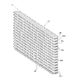
- FIG. 2 is a schematic perspective view of the outdoor heat exchanger 11.
- FIG. 3 is a partially enlarged view of the heat exchange section 27 described later of the outdoor heat exchanger 11.
- FIG. 4 is a schematic view showing a state in which the fin 29, which will be described later, is attached to the flat tube 28 in the heat exchange unit 27.
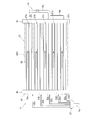
- FIG. 5 is a schematic configuration diagram of the outdoor heat exchanger 11. The arrow of the heat exchange unit 27 shown in FIG. 5 indicates the flow of the refrigerant during the heating operation (when the outdoor heat exchanger 11 functions as an evaporator).
- the outdoor heat exchanger 11 is a device that exchanges heat between the refrigerant flowing inside and the air.
- the outdoor heat exchanger 11 includes a shunt 22, a flat tube group 28G including a plurality of flat tubes 28 (examples of heat transfer tubes), a plurality of fins 29, a liquid header 40 (examples of headers), and a gas header 70.
- a shunt 22, the flat tube 28, the fins 29, the liquid header 40, and the gas header 70 are all made of aluminum or an aluminum alloy.
- the outdoor heat exchanger 11 has one row of heat exchange portions 27, and a plurality of flat tubes 28 are not arranged in the air flow direction.
- the exchange takes place.
- the heat exchange units 27 are arranged in the vertical direction, that is, the first heat exchange unit 27a, the second heat exchange unit 27b, the third heat exchange unit 27c, the fourth heat exchange unit 27d, and the fifth heat exchange unit 27e. And, (see FIG. 2).
- the shunt 22 is a mechanism for splitting the refrigerant.
- the shunt 22 is also a mechanism for merging the refrigerant.
- a liquid refrigerant pipe 20 is connected to the shunt 22.
- the shunt 22 has a plurality of shunt pipes 22a to 22e.
- the shunt 22 has a function of dividing the refrigerant flowing into the shunt 22 from the liquid refrigerant pipe 20 into a plurality of shunt pipes 22a to 22e and guiding the refrigerant into a plurality of spaces formed in the liquid header 40.
- the shunt 22 has a function of merging the refrigerant flowing from the liquid header 40 through the shunt pipes 22a to 22e and guiding the refrigerant to the liquid refrigerant pipe 20.
- the flow dividing pipes 22a to 22e and the plurality of spaces in the liquid header 40 are connected via the branched liquid refrigerant connecting pipes 49a to 49e, respectively.
- the flat tube group 28G is an example of a heat transfer tube group.
- the flat tube group 28G includes a plurality of flat tubes 28 as a plurality of heat transfer tubes.
- the flat tube 28 is a flat heat transfer tube having flat surfaces 28a which are heat transfer surfaces at the top and bottom as shown in FIG.
- a plurality of refrigerant passages 28b through which the refrigerant flows are formed in the flat pipe 28.
- the flat pipe 28 is a flat multi-hole pipe in which a large number of refrigerant passages 28b having a small passage cross-sectional area through which the refrigerant flows are formed.
- These plurality of refrigerant passages 28b are provided side by side in the air flow direction in the present embodiment.
- the maximum width of the flat pipe 28 in the cross section perpendicular to the refrigerant passage 28b may be 70% or more, or 85% or more, of the outer diameter of the main gas refrigerant pipe connecting portion 19a.
- flat pipes 28 extending in the horizontal direction between the liquid header 40 side and the gas header 70 side are arranged vertically in a plurality of stages.
- the flat tube 28 extending between the liquid header 40 side and the gas header 70 side is bent at two points, and the heat exchange portion 27 formed by the flat tube 28 is substantially U-shaped in a plan view. It is formed in a shape (see FIG. 2).
- the plurality of flat tubes 28 are arranged vertically at regular intervals.
- the plurality of fins 29 are members for increasing the heat transfer area of the outdoor heat exchanger 11.
- Each fin 29 is a plate-shaped member extending in the step direction in which the flat tubes 28 are arranged.
- the outdoor heat exchanger 11 is used in a mode in which a plurality of horizontally extending flat tubes 28 are arranged side by side in the vertical direction. Therefore, when the outdoor heat exchanger 11 is installed in the outdoor unit 2, each fin 29 extends in the vertical direction.
- a plurality of notches 29a extending along the insertion direction of the flat tube 28 are formed in each fin 29 so that a plurality of flat tubes 28 can be inserted.
- the notch 29a extends in the extending direction of the fin 29 and in the direction orthogonal to the thickness direction of the fin 29.
- the notch 29a formed in each fin 29 extends in the horizontal direction.
- the shape of the notch 29a of the fin 29 substantially matches the shape of the outer shape of the cross section of the flat tube 28.
- the notch 29a is formed in the fin 29 with an interval corresponding to the arrangement interval of the flat tubes 28.
- the plurality of fins 29 are arranged side by side along the extending direction of the flat tube 28.
- the adjacent flat tubes 28 are partitioned into a plurality of ventilation passages through which air flows.
- Each fin 29 has a communication portion 29b that communicates vertically with respect to the flat pipe 28 on the upstream side or the downstream side in the air flow direction.
- the communication portion 29b of the fin 29 is located on the windward side of the flat pipe 28.
- each flat tube 28 is connected to the liquid header 40, and the other end of each flat tube 28 is connected to the gas header 70.
- the outdoor heat exchanger 11 is arranged in a casing (not shown) of the outdoor unit 2 so that the longitudinal directions of the liquid header 40 and the gas header 70 substantially coincide with the vertical direction.
- the heat exchange portion 27 of the outdoor heat exchanger 11 is formed in a U-shape in a plan view as shown in FIG.
- the liquid header 40 is arranged near the left front corner of the casing (not shown) of the outdoor unit 2 (see FIG. 2).
- the gas header 70 is arranged near the right front corner of the casing (not shown) of the outdoor unit 2 (see FIG. 2).
- the gas header 70 is connected to a main gas refrigerant pipe connecting portion 19a and a branch gas refrigerant pipe connecting portion 19b forming an end on the gas header 70 side of the first gas refrigerant pipe 19 (see FIG. 5).
- the outer diameter of the main gas refrigerant pipe connecting portion 19a may be, for example, three times or more, or five times or more, the outer diameter of the branched gas refrigerant pipe connecting portion 19b.
- One end of the main gas refrigerant pipe connecting portion 19a is connected to the gas header 70 so as to communicate with the gas side internal space 25 at an intermediate position in the height direction of the gas header 70.
- One end of the branched gas refrigerant pipe connecting portion 19b is connected to the gas header 70 so as to communicate with the gas side internal space 25 in the vicinity of the lower end in the height direction of the gas header 70.
- the other end of the branched gas refrigerant pipe connecting portion 19b is connected to the main gas refrigerant pipe connecting portion 19a.
- the branched gas refrigerant pipe connecting portion 19b has an inner diameter smaller than that of the main gas refrigerant pipe connecting portion 19a, and is connected to the gas header 70 below the main gas refrigerant pipe connecting portion 19a to stay near the lower end of the gas header 70. It is possible to return the refrigerating machine oil to the compressor 8.
- These plurality of subspaces 23a to 23e are arranged in the vertical direction.
- the sub-spaces 23a to 23e are in a non-communication state in the liquid-side internal space 23 of the liquid header 40.
- the branch liquid refrigerant connecting pipes 49a to 49e (example of the first pipe) connected to the respective shunt pipes 22a to 22e of the shunt 22 are connected one-to-one. ..
- the refrigerants that have reached the sub-spaces 23a to 23e flow through the branch liquid refrigerant connecting pipes 49a to e and the flow dividing pipes 22a to 22e, and merge in the shunt 22.
- the refrigerant shunted by the shunt 22 flows through the shunt pipes 22a to 22e and the branch liquid refrigerant connection pipes 49a to 49e, and is supplied to the subspaces 23a to 23e. Become.
- the refrigerant flowing through the diversion pipe 22a flows into the sub space 23a
- the refrigerant flowing through the diversion pipe 22b flows into the sub space 23b
- the refrigerant flowing through the diversion pipe 22c flows into the sub space 23c
- the refrigerant flowing through the diversion pipe 22e flows into the sub space 23e.
- the refrigerant that has flowed into the subspaces 23a to 23e of the liquid side internal space 23 flows through the flat pipes 28 connected to the subspaces 23a to 23e.
- the refrigerant flowing through each of the flat tubes 28 evaporates by exchanging heat with air, becomes a gas phase refrigerant, and flows into the gas side internal space 25 of the gas header 70 to merge.
- the refrigerant flows in the refrigerant circuit 6 in the opposite direction to that during the heating operation.
- the high-temperature gas-phase refrigerant flows into the gas-side internal space 25 of the gas header 70 via the main gas refrigerant pipe connecting portion 19a and the branch gas refrigerant pipe connecting portion 19b of the first gas refrigerant pipe 19.
- the refrigerant that has flowed into the gas-side internal space 25 of the gas header 70 is split and flows into each flat pipe 28.
- the refrigerant that has flowed into the flat pipes 28 passes through the flat pipes 28 and flows into the subspaces 23a to 23e of the liquid side internal space 23 of the liquid header 40.
- the refrigerant that has flowed into the subspaces 23a to 23e of the liquid side internal space 23 merges with the shunt 22 and flows out to the liquid refrigerant pipe 20.
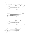
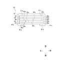
- FIG. 7 shows a side view external configuration diagram showing how the branched liquid refrigerant connecting pipes 49a to 49e are connected to the liquid header 40.
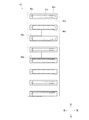
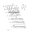
- FIG. 8 shows an exploded perspective view of the liquid header 40.
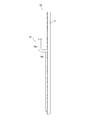
- FIG. 9 shows a sectional view of the liquid header 40 in a plan view.
- FIG. 10 is a plan sectional view showing how the branched liquid refrigerant connecting pipes 49a to 49e and the flat pipe 28 are connected to the liquid header 40.
- FIG. 11 shows a schematic view of the second liquid side member 41 as viewed from the rear side.
- FIG. 12 shows a schematic view of the sixth liquid side member 42 as viewed from the rear side.
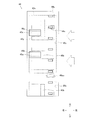
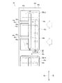
- FIG. 13 shows a schematic view of the fifth liquid side member 43 as viewed from the rear side.
- FIG. 14 shows a schematic view of the fourth liquid side member 44 as viewed from the rear side.
- FIG. 15 shows a schematic view of the third liquid side member 45 as viewed from the rear side.
- FIG. 16 shows a schematic view of the first liquid side member 46 as viewed from the rear side.
- the liquid header 40 includes a first liquid side member 46, a second liquid side member 41, a third liquid side member 45, a fourth liquid side member 44, a fifth liquid side member 43, and a sixth liquid side member. It has 42 and.
- the first liquid side member 46, the second liquid side member 41, the third liquid side member 45, the fourth liquid side member 44, the fifth liquid side member 43, and the sixth liquid side member 42 are brazed to each other. It is constructed by joining by brazing.
- the liquid header 40 is configured so that the outer shape in a plan view has a substantially quadrangular shape having a connection point of the flat tube 28 as one side.
- the second liquid side member 41 is a member that mainly constitutes the periphery of the outer shape of the liquid header 40 together with the first liquid side member 46 described later.
- the second liquid side member 41 preferably has a clad layer having a brazing material formed on its surface.
- the second liquid side member 41 includes a liquid side flat tube connecting plate 41a, a first liquid side outer wall 41b, a second liquid side outer wall 41c, a first liquid side claw portion 41d, and a second liquid side claw portion 41e. ,have.
- the second liquid side member 41 of the present embodiment can be formed by bending one sheet metal obtained by rolling with the longitudinal direction of the liquid header 40 as a crease.
- the plate thickness of each portion of the second liquid side member 41 is uniform and has the thickness on the first liquid side.
- the liquid-side flat tube connecting plate 41a (example of the second plate-shaped portion) is a flat plate-shaped portion that extends in the vertical direction (example of the first direction) and in the horizontal direction (example of the second direction).
- the liquid-side flat tube connecting plate 41a is formed with a plurality of liquid-side flat tube connecting openings 41x arranged side by side in the vertical direction.
- Each liquid side flat tube connection opening 41x is an opening penetrating in the thickness direction of the liquid side flat tube connection plate 41a.
- the flat tube 28 is joined by brazing in a state where the flat tube 28 is inserted into the liquid side flat tube connection opening 41x so that one end of the flat tube 28 completely passes through.
- the entire inner peripheral surface of the liquid side flat tube connection opening 41x and the entire outer peripheral surface of the flat tube 28 are in contact with each other.
- the thickness of the first liquid side which is the thickness of the second liquid side member 41 including the liquid side flat tube connecting plate 41a, is formed to be relatively thin, for example, about 1.0 mm or more and 2.0 mm or less.
- the length of the inner peripheral surface of the gas-side flat pipe connection opening 71x in the plate thickness direction can be shortened.
- the inner peripheral surface of the liquid side flat tube connection opening 41x and the outer peripheral surface of the flat tube 28 It is possible to suppress the friction generated between the tube and the tube to facilitate the insertion operation.
- the first liquid side outer wall 41b is a flat portion extending toward the front side from the front side surface of the end portion of the left side (outside of the outdoor unit 2, the side opposite to the gas header 70) of the liquid side flat pipe connecting plate 41a. Is.
- the second liquid side outer wall 41c is a flat portion extending toward the front side from the front side surface of the end portion on the right side (inside of the outdoor unit 2, gas header 70 side) of the liquid side flat pipe connecting plate 41a.
- the first liquid side claw portion 41d is a portion extending toward the right side from the front end portion of the first liquid side outer wall 41b.
- the second liquid side claw portion 41e is a portion extending from the front end portion of the second liquid side outer wall 41c toward the left side.
- the first liquid side claw portion 41d and the second liquid side claw portion 41e are the sixth liquid side member 42, the fifth liquid side member 43, and the fourth liquid side member 44 inside the second liquid side member 41 in a plan view.
- the third liquid side member 45 and the first liquid side member 46 they are in a state of extending on the extension of the first liquid side outer wall 41b and the second liquid side outer wall 41c, respectively.
- the sixth liquid side member 42, the fifth liquid side member 43, the fourth liquid side member 44, the third liquid side member 45, and the first liquid side member 46 are arranged inside the second liquid side member 41 in a plan view.
- the sixth liquid side member 42, the fifth liquid side member 43, and the fourth liquid side member 44 are bent.
- the third liquid side member 45 and the first liquid side member 46 are fixed to each other by being crimped by the second liquid side member 41. Then, in this state, brazing is performed in a furnace or the like, so that the members are joined by brazing and completely fixed.
- the 6th liquid side member 42 is the front side of the liquid side flat pipe connecting plate 41a of the 2nd liquid side member 41 (connection between the branch liquid refrigerant connecting pipes 49a to e and the liquid header 40). It is a member laminated so as to face and contact the surface (position side).
- the left and right lengths of the sixth liquid side member 42 are the same as the left and right lengths of the liquid side flat pipe connecting plate 41a of the second liquid side member 41 excluding both ends.
- the sixth liquid side member 42 preferably has a clad layer having a brazing material formed on its surface.
- the sixth liquid side member 42 has a sixth inner plate 42a and a plurality of sixth openings 42x.
- the sixth inner plate 42a (example of the fourth plate-shaped portion) has a flat plate shape extending in the vertical direction and in the horizontal direction.
- the plurality of sixth openings 42x (examples of connecting openings) are arranged side by side in the vertical direction and penetrate the sixth inner plate 42a in the plate thickness direction.
- Each sixth opening 42x is an opening larger than each liquid side flat pipe connecting opening 41x formed on the liquid side flat pipe connecting plate 41a of the second liquid side member 41.
- the outer edge of each sixth opening 42x is more specifically front and back in the stacking direction of each member. In the direction, it is configured to be located outside the outer edge of each liquid side flat pipe connecting opening 41x formed in the liquid side flat pipe connecting plate 41a of the second liquid side member 41.
- the upper and lower portions of the outer edge of each of the sixth openings 42x may be separated from the upper and lower portions of the outer edge of each liquid side flat tube connecting opening 41x of the liquid side flat tube connecting plate 41a by 2 mm or more. It is preferable that they are separated.
- the fifth liquid side member 43 faces the front side of the sixth liquid side member 42 (the connection position side between the branch liquid refrigerant connecting pipes 49a to e and the liquid header 40). It is a member laminated so as to be in contact with each other.
- the left and right lengths of the fifth liquid side member 43 are the same as the left and right lengths of the sixth liquid side member 42.
- the fifth liquid side member 43 preferably has a clad layer having a brazing material formed on its surface.
- the fifth liquid side member 43 has a fifth inner plate 43a and a plurality of fifth openings 43x.
- the fifth inner plate 43a (example of the fourth plate-shaped portion) has a flat plate shape extending in the vertical direction and in the horizontal direction.
- the plurality of fifth openings 43x are arranged side by side in the vertical direction and penetrate the fifth inner plate 43a in the plate thickness direction.
- each of the fifth openings 43x are located inside the sixth opening 42x of the sixth liquid side member 42 in the stacking direction view, and are formed on the liquid side flat pipe connecting plate 41a of the second liquid side member 41. It is an opening located inside the liquid-side flat tube connection opening 41x and inside the left and right widths of the flat tube 28.
- the upper and lower edges of each of the fifth openings 43x are located inside the sixth opening 42x of the sixth liquid side member 42 in the stacking direction, and the liquid side flat pipe connecting plate 41a of the second liquid side member 41. It is an opening located outside each liquid side flat tube connection opening 41x formed in.
- the fourth liquid side member 44 faces the front side of the fifth liquid side member 43 (the connection position side between the branch liquid refrigerant connecting pipes 49a to e and the liquid header 40). It is a member laminated so as to be in contact with each other.
- the left and right lengths of the fourth liquid side member 44 are the same as the left and right lengths of the fifth liquid side member 43.
- the fourth liquid side member 44 preferably has a clad layer having a brazing material formed on its surface.
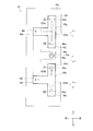
- the fourth liquid side member 44 has a fourth inner plate 44a, a plurality of fourth ascending side openings 44x, and a plurality of fourth descending side openings 44y.
- the fourth inner plate 44a (example of the fourth plate-shaped portion) has a flat plate shape extending in the vertical direction and in the horizontal direction.
- the fourth ascending side opening 44x is also fourthly lowered at a position overlapping the introduction space 51 of the first penetrating portion 45x of the third liquid side member 45.
- the side opening 44y is not provided, and the wall portion 44aa is widened.
- the plurality of fourth ascending side openings 44x are arranged side by side in the vertical direction and penetrate the fourth inner plate 44a in the plate thickness direction.
- Each of the fourth ascending side openings 44x is arranged on the upstream side in the air flow direction generated by the outdoor fan 16 with respect to each of the fourth descending side openings 44y.
- the air flow generated by the outdoor fan 16 is indicated by a dotted arrow.
- the edge of each of the fourth rising side openings 44x is located inside the edge of the fifth opening 43x of the fifth liquid side member 43 in the stacking direction view.
- each of the fourth rising side openings 44x is arranged on the upstream side of the center of the flat pipe 28 in the plan view in the air flow direction generated by the outdoor fan 16. Therefore, when the outdoor heat exchanger functions as an evaporator of the refrigerant, it is possible to guide a large amount of the refrigerant that has passed through each of the fourth rising side openings 44x to the windward side of each of the flat pipes 28. As a result, a large amount of refrigerant is guided to the windward side where it is easier to secure the temperature difference between the air and the refrigerant, and the heat exchange performance can be improved.
- the plurality of fourth descending side openings 44y are arranged side by side in the vertical direction and penetrate the fourth inner plate 44a in the plate thickness direction.
- Each of the fourth lowering side openings 44y is provided at a position that does not overlap with the fifth opening 43x of the fifth liquid side member 43 in the stacking direction view.
- each of the fourth descending side openings 44y is at a position overlapping the connecting portion 45c of the third liquid side member 45, which will be described later, in the stacking direction view, and the fifth liquid side member 43 is vertically adjacent to each other. It is arranged at a position between the five openings 43x in the vertical direction.
- the space in each of the fifth openings 43x of the fifth liquid side member 43 and the space in the fourth descending side opening 44y of the fourth liquid side member 44 do not communicate with each other in the stacking direction and are directly connected. Is not in communication. Therefore, the refrigerant flowing through the descending space 55, which will be described later, does not reach each of the fifth openings 43x of the fifth liquid side member 43 by moving to the front side.
- the upper end of the fourth descending side opening 44y is located further above the upper end of the corresponding connecting portion 45c so as to overlap, and the lower end of the fourth descending side opening 44y overlaps. It is located further below the lower end of the corresponding contact section 45c.
- a plate-shaped portion of the fourth inner plate 44a extends between the vertical directions of each of the fourth ascending side openings 44x. Similarly, a plate-shaped portion of the fourth inner plate 44a extends between the plurality of fourth descending side openings 44y in the vertical direction.
- the third liquid side member 45 faces the front side of the fourth liquid side member 44 (the connection position side between the branch liquid refrigerant connecting pipes 49a to e and the liquid header 40). It is a member laminated so as to be in contact with each other. The left and right lengths of the third liquid side member 45 are the same as the left and right lengths of the fourth liquid side member 44.
- the third liquid side member 45 preferably has a clad layer having a brazing material formed on its surface.
- the third liquid side member 45 has a third inner plate 45a, a plurality of first penetrating portions 45x, and a plurality of second penetrating portions 45y.
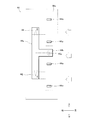
- the third inner plate 45a (example of the third plate-shaped portion, example of the portion in contact with the partition portion) has a flat plate shape extending in the vertical direction and in the horizontal direction.
- the third inner plate 45a is a partition portion 45b extending in the longitudinal direction of the liquid header 40 so as to partition the left and right spaces while creating a gap between the first through portion 45x and the vertical end portion. Corresponds to each first penetrating portion 45x.
- the third inner plate 45a has a connecting portion 45c extending from the vicinity of the right edge portion formed by the outdoor fan 16 on the downstream side in the air flow direction to the partition portion 45b.
- two connecting portions 45c arranged vertically extend from one partition portion 45b.
- the thickness of each portion of the third inner plate 45a in the plate thickness direction is uniform including the partition portion 45b and the connecting portion 45c.
- the connecting portion 45c and the fourth descending side opening 44y are located so that only a part thereof overlaps.
- an upper detour opening 44p penetrating in the plate thickness direction is formed above the connecting portion 45c in the upper region of the fourth descending side opening 44y, and of the fourth descending side opening 44y.
- the third liquid side member 45 and the fourth liquid side member 44 are arranged so as to form a lower detour opening 44q penetrating in the plate thickness direction on the lower side of the connecting portion 45c.
- the plurality of first penetrating portions 45x are arranged side by side in the vertical direction, and are openings penetrating in the plate thickness direction of the fourth inner plate 44a.
- a plurality of fourth ascending side openings 44x overlap each other in the first penetrating portion 45x in the stacking direction view.
- One introduction space 51 (example of communication area), one nozzle 52 (example of connection area), one rising space 53 (example of first area), and one in one first penetration portion 45x.
- One forward flow path 54 (example of the second region), a part of one descending space 55 (example of the third region), and one return flow path 56 (example of the fourth region) are included.
- the fourth lowering side opening 44y of the fourth liquid side member 44 constitutes another part of the lowering space 55.
- the nozzle 52 is located below any of the fourth liquid side members 44 communicating with the first penetrating portion 45x where the nozzle 52 is provided.
- the nozzle 52, the forward flow path 54, and the return flow path 56 are all the rear surface of the liquid side outer plate 46a of the first liquid side member 46, which will be described later, and the fourth liquid side member 44. 4
- the space is surrounded by the front surface of the inner plate 44a.
- the rear side of the introduction space 51 is covered with the front surface of the wall portion 44aa of the fourth inner plate 44a of the fourth liquid side member 44, and the front side is the first liquid side member 46 described later.
- the branch liquid refrigerant connecting pipes 49a to 49e connected to the external liquid pipe connecting opening 46x of the liquid side outer plate 46a communicate with each other.
- the front side is covered with the rear surface of the liquid side outer plate 46a of the first liquid side member 46, which will be described later, and the rear side is the fourth ascending of the fourth liquid side member 44.
- the portion other than the portion where the side opening 44x is provided is covered with the front surface of the fourth inner plate 44a of the fourth liquid side member 44.
- the fourth rising side opening 44x of the fourth liquid side member 44 communicates with the rising space 53 of the third liquid side member 45, and the introduction space 51, the nozzle 52, and the outgoing flow path in the third liquid side member 45. It does not communicate with 54, the descending space 55, or the return flow path 56.
- the front side is covered with the rear surface of the liquid side outer plate 46a of the first liquid side member 46, which will be described later, and the connecting portion 45c of the fourth liquid side member 44.
- the portion where the fourth descending side opening 44y is not provided is covered with the front surface of the fourth inner plate 44a of the fourth liquid side member 44, and the fourth liquid The portion of the side member 44 where the fourth lowering side opening 44y is provided is covered with the front surface of the fifth inner plate 43a of the fifth liquid side member 43.
- a circulation flow path structure including a flow path 54, a descending space 55, and a return flow path 56 is configured.
- the circulation flow path structure is provided side by side in the vertical direction so as to have a one-to-one correspondence with the branch liquid refrigerant connecting pipes 49a to e.
- the introduction space 51, the nozzle 52, and the rising space 53 are arranged in the longitudinal direction of the liquid header 40.
- the introduction space 51, the nozzle 52, and the rising space 53 are arranged in order from the bottom.
- the left edge of the nozzle 52 is located to the right of the left edge of the introduction space 51 and to the right of the left edge of the rising space 53. Further, the right edge of the nozzle 52 is located on the left side of the right edge of the introduction space 51, and is located on the left side of the right edge of the rising space 53.
- the width of the nozzle 52 in the left-right direction is shorter than the width of the introduction space 51 in the left-right direction and shorter than the width of the rising space 53 in the left-right direction.
- the refrigerant heading from the introduction space 51 to the ascending space 53 can increase the flow velocity when passing through the nozzle 52 having a narrowed passage cross-sectional area. Then, the refrigerant that has been increased in flow velocity and has flowed into the ascending space 53 can reach the fourth ascending side opening 44x located far above the nozzle 52.
- the branch liquid refrigerant connecting pipes 49a to 49e overlap and are connected at the overlapping portion A including the center in the left-right direction of the introduction space 51.
- the overlapping portion A which is the connection portion between the introduction space 51 and the corresponding branch liquid refrigerant connection pipes 49a to 49e, the nozzle 52, and the ascending space 53 are arranged in the vertical direction. Have been placed. Therefore, the refrigerant flowing through the branch liquid refrigerant connecting pipes 49a to 49e flows into the center of the introduction space 51 in the left-right direction through the external liquid pipe connecting opening 46x described later, and does not move in the left-right direction or.
- the nozzle 52 can be blown up vertically upward from the introduction space 51 toward the ascending space 53 via the nozzle 52 without moving too much in the left-right direction.
- the refrigerant passing through the nozzle 52 flows unevenly toward the upper right, and the region refrigerant on the right side of the introduction space 51 flows in. If this is the case, the refrigerant passing through the nozzle 52 may flow unevenly toward the upper left, but the structure of the present embodiment makes it possible to suppress such bias.
- the upper end of the ascending space 53 and the upper end of the descending space 55 are communicated with each other by the forward flow path 54. Further, the lower end portion of the ascending space 53 and the lower end portion of the descending space 55 are communicated with each other by the return flow path 56.
- the area of the forward flow path 54 is larger than the area of the return flow path 56. Is also formed large. Specifically, in the present embodiment, the longitudinal width of the liquid header 40 in the forward flow path 54 is formed longer than the longitudinal width of the liquid header 40 in the return flow path 56. As a result, the refrigerant that has risen in the rising space 53 and reached the vicinity of the upper end can easily pass through the outbound flow path 54.
- the area of the return flow path 56 is larger than the area of the forward flow path 54. Is also formed small. Specifically, in the present embodiment, the width of the liquid header 40 in the return flow path 56 in the longitudinal direction is shorter than the width of the liquid header 40 in the forward flow path 54 in the longitudinal direction. As a result, it is possible to prevent the refrigerant from flowing back from the rising space 53 to the return flow path 56.
- the plurality of second penetrating portions 45y are arranged vertically on the right side, which is the downstream side in the air flow direction formed by the outdoor fan 16. It is an opening that is arranged and penetrates in the plate thickness direction of the fourth inner plate 44a.
- One second penetrating portion 45y is surrounded by one partition portion 45b, two connecting portions 45c extending from the one partition portion 45b, and an edge portion near the right end portion of the third inner plate 45a. It is an open opening.
- the first liquid side member 46 is a member laminated so as to face and contact the front surface of the third inner plate 45a of the third liquid side member 45.
- the left and right lengths of the first liquid side member 46 are the same as the left and right lengths of the third liquid side member 45, the fourth liquid side member 44, the fifth liquid side member 43, and the sixth liquid side member 42. It is the same as the left and right length of the portion of the liquid side flat tube connecting plate 41a of the second liquid side member 41 excluding both ends.
- the first liquid side member 46 preferably has a clad layer having a brazing material formed on its surface.
- the first liquid side member 46 has a liquid side outer plate 46a.
- the liquid side outer plate 46a (example of the first plate-shaped portion) has a flat plate shape extending in the vertical direction and in the horizontal direction.
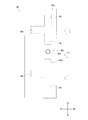
- the liquid side outer plate 46a is provided with a plurality of external liquid pipe connection openings 46x into which the branch liquid refrigerant connection pipes 49a to e are inserted and connected.
- the external liquid pipe connection opening 46x (example of the pipe connection opening) is an opening penetrating the liquid side outer plate 46a in the plate thickness direction.
- the plurality of external liquid pipe connection openings 46x are arranged along the longitudinal direction of the liquid header 40. In the present embodiment, each external liquid pipe connection opening 46x is arranged unevenly on the windward side of the liquid side outer plate 46a, and is arranged so that the center is located directly below the nozzle 52 in the stacking direction view. There is.
- the branched liquid refrigerant connecting pipes 49a to 49 of the first liquid side member 46 have the external liquid pipe connecting opening 46x
- the third liquid side member 45 has the first penetrating portion 45x
- the fourth liquid side member 44 has. It is in a state of communicating with a plurality of flat tubes 28 via the fourth rising side opening 44x and the fifth opening 43x of the fifth liquid side member 43.
- the front surface of the first liquid side member 46 is caulked in contact with the first liquid side claw portion 41d and the second liquid side claw portion 41e of the second liquid side member 41.
- the liquid refrigerant or the gas-liquid two-phase state refrigerant that has been shunted into the plurality of shunt pipes 22a to 22e in the shunt 22 flows through the branched liquid refrigerant connecting pipes 49a to 49, and thus the second liquid side member 41. It passes through the external liquid pipe connection opening 46x of the liquid side outer plate 46a and flows into the subspaces 23a to 23e of the liquid header 40.
- the refrigerant flowing into the introduction space 51 hits the wall portion 44aa of the fourth inner plate 44a of the fourth liquid side member 44, so that the flow path is narrowed after the vapor phase refrigerant and the liquid phase refrigerant are mixed.
- the flow velocity is increased and flows into the ascending space 53. Since the width of the rising space 53 in the left-right direction is narrowed by the partition portion 45b, even when the refrigerant circulation amount of the refrigerant circuit 6 is small, such as when the drive frequency of the compressor 8 is small.
- the refrigerant that has flowed into the ascending space 53 can easily reach the fourth ascending side opening 44x located near the upper end of the ascending space 53.
- the refrigerant that has flowed into the ascending space 53 flows toward the upper end of the ascending space 53 while splitting and flowing toward each of the fourth ascending side openings 44x.
- the amount of refrigerant circulating in the refrigerant circuit 6 is large, such as when the drive frequency of the compressor 8 is high, the amount of refrigerant reaching the vicinity of the upper end of the ascending space 53 increases, and the descending space passes through the outgoing flow path 54.
- the refrigerant reaches up to 55.
- the refrigerant that has reached the descending space 55 descends and is returned to the space above the nozzle 52 in the lower vicinity of the ascending space 53 again via the return flow path 56.
- the static pressure of the portion near the return flow path 56 of the ascending space 53 is smaller than that of the portion near the return flow path 56 of the descending space 55. Become. Therefore, the refrigerant that has descended from the descending space 55 is likely to be returned to the ascending space 53 via the return flow path 56.
- the refrigerant can be circulated by the ascending space 53, the forward flow path 54, the descending space 55, and the return flow path 56, any of the first ones when ascending and flowing through the ascending space 53 4
- a refrigerant that has branched to the ascending side opening 44x and does not flow it can be returned to the ascending space 53 via the outgoing flow path 54, the descending space 55, and the returning flow path 56, so that any one of them can be used. It is easy to flow through the fourth rising side opening 44x.
- the refrigerant descending in the descending space 55 mainly descends the region on the right side of the first penetrating portion 45x provided on the third inner plate 45a of the third liquid side member 45 and the second penetrating portion 45y. It flows. More specifically, the refrigerant descending in the descending space 55 is the rear surface of the liquid-side outer plate 46a of the first liquid-side member 46 and the fourth of the fourth liquid-side member 44 in the portion where the connecting portion 45c is not provided. It flows down the region between the inner plate 44a and the front surface, and flows so as to bypass the connecting portion 45c at the portion where the connecting portion 45c is present.
- the refrigerant flows into the fourth descending side opening 44y of the fourth liquid side member 44 through the upper detour opening 44p, and then flows through the lower detour opening 44q to the third liquid side member. It flows back to the first penetrating portion 45x or the second penetrating portion 45y of 45.
- the refrigerant that has been diverted and flowed into each of the fourth rising side openings 44x of the fourth liquid side member 44 is maintained in the separated state, and the fifth opening 43x of the fifth liquid side member 43 is maintained. And flow into each flat tube 28.
- the liquid header 40 of the outdoor heat exchanger 11 of the present embodiment has a structure in which a plurality of subspaces 23a to 23e are vertically partitioned in the liquid side internal space 23 by laminating plate-shaped portions of a plurality of members with each other. Has been realized. As a result, it is not necessary to insert and fix a plurality of horizontally spread partition plates to the cylindrical header in order to form a plurality of spaces arranged vertically in the cylindrical header as in the conventional case. become.
- the flat tube which is a flat heat transfer tube
- the flat tube will be largely inserted into the cylindrical header, and the flat tube will be flat. Wasteful space where the refrigerant tends to stay is generated above and below the portion of the pipe located in the cylindrical header.
- the inner diameter of the cylindrical header needs to be large enough to include at least the entire end of the flat tube, the space in the cylindrical header tends to be large, and the shaft in the header tends to be large. When the refrigerant flows in the direction, the passing cross-sectional area becomes large, and it is difficult to increase the flow velocity of the refrigerant.
- the refrigerant may stay.
- the wasted space can be reduced.
- the size of the space through which the refrigerant flows in the longitudinal direction of the liquid header 40 can be easily adjusted by simply adjusting the plate thickness and the size of the opening of the plate-shaped member, and the passage cross-sectional area of the refrigerant can be adjusted. It is also possible to increase the flow velocity of the refrigerant by reducing the value.
- the liquid header 40 is formed in the first penetrating portion 45x formed in the third inner plate 45a of the third liquid side member 45 with respect to the rising space 53 extending in the longitudinal direction of the liquid header 40.
- the forward flow path 54 and the return flow path 56 extending in the left-right direction, which is a direction different from the longitudinal direction of the above, are connected.
- the direction in which the refrigerant flows can be changed by the shape of the penetrating portion of one plate-shaped member. Therefore, it is possible to reduce the number of plate-shaped members required to change the direction in which the refrigerant flows in the liquid header 40.
- the rising space 53 of the first penetrating portion 45x formed in the third inner plate 45a of the third liquid side member 45 is set in the longitudinal direction of the rising space 53. It is arranged at a position biased to one side with respect to the center of the third inner plate 45a in the vertical direction. Therefore, the region on the opposite side of the center of the third inner plate 45a in the direction perpendicular to the longitudinal direction of the rising space 53 can be effectively used for other usage functions other than the usage function of the rising space 53. It has become.
- the width of the rising space 53 in the left-right direction can be narrowed by forming the partition portion 45b. Therefore, even if the amount of refrigerant circulating in the refrigerant circuit 6 is small, such as when the amount of refrigerant sent to the liquid header 40 is small, the refrigerant flowing so as to rise in the ascending space 53 is passed through the upper end of the ascending space 53. It is possible to sufficiently supply the flat tube 28 connected in the vicinity. Further, even if the amount of refrigerant circulated in the refrigerant circuit 6 is large, such as when the amount of refrigerant sent to the liquid header 40 is large, the refrigerant that has reached the upper end of the rising space 53 without being sent to the flat pipe 28. Can be sent to the flat tube 28 again via the forward flow path 54, the descending space 55, and the return flow path 56.
- the third inner plate 45a of the third liquid side member 45 has a partition portion 45b and a connecting portion 45c integrated. Therefore, even when a flow path for circulating and flowing the refrigerant is formed within the plate thickness of the third liquid side member 45, it can be realized by one member without dividing the member into a plurality of members. ..
- the fourth lowering side opening 44y of the fourth liquid side member 44 is located so as to face the connecting portion 45c of the third liquid side member 45, and communicates with a part of the contour of the fourth lowering side opening 44y.
- An upper detour opening 44p and a lower detour opening 44q are formed at a part of the edge of the portion 45c.
- the refrigerant flowing from the ascending space 53 in each of the fourth ascending side openings 44x is a flat pipe 28.
- the front side of the rising space 53 is covered with the rear surface of the liquid side outer plate 46a of the first liquid side member 46 described later, and the rear side. Is covered by the front surface of the fourth inner plate 44a of the fourth liquid side member 44, except for the portion where the fourth rising side opening 44x of the fourth liquid side member 44 is provided. Therefore, regardless of the degree of insertion of each flat pipe 28 in the liquid header 40, it is possible to stably secure the flow path cross-sectional area of the rising space 53 for raising and flowing the refrigerant.
- the second liquid side member 41 including the liquid side flat pipe connecting plate 41a is formed relatively thin. Therefore, when the flat tube 28 is inserted into the liquid side flat tube connection opening 41x in the pre-stage of joining by brazing, the inner peripheral surface of the liquid side flat tube connection opening 41x and the outer peripheral surface of the flat tube 28 It is possible to suppress the friction generated between the tube and the tube to facilitate the insertion operation.
- the sixth liquid side member 42 is further laminated on the liquid side flat pipe connecting plate 41a in the plate thickness direction. ing. Therefore, it is possible to increase the pressure resistance strength of the portion of the liquid header 40 on the side to which the flat tube 28 is connected.
- the third inner plate 44a is spread flat while omitting the fourth lowering side opening 44y in the fourth liquid side member 44 of the above embodiment.
- the thickness of the connecting portion 145c of the inner plate 45a may be thinner than the thickness of the partition portion 45b and other portions. Even in this form, the thin connecting portion 145c, the rear surface of the liquid side outer plate 46a of the first liquid side member 46, and the front surface of the fourth inner plate 44a of the fourth liquid side member 44. It becomes possible to flow the refrigerant through the gap between the and.
- the third liquid side member 45 having a thinly configured connecting portion 145c may be used. In this case, it becomes possible to improve the flow of the refrigerant around the connecting portion 145c.
- FIG. 18 is a schematic view of the third liquid side member 45 viewed from the rear side, and has a fourth opening 144x (example of a connecting opening) of the fourth liquid side member 44 laminated on the rear side and a front side. The positional relationship between the laminated first liquid side member 46 and the external liquid pipe connection opening 46x is also shown.
- the penetration portion 145x includes an introduction space 151, a nozzle 152, an ascending space 153, a first branch space 154, a first branch space 155, a second branch space 156, a third branch space 157, and a second branch space. It has a space 158, a third diversion space 159, a first end portion 161 and a second end portion 162, a third end portion 163, and a fourth end portion 164. In FIG. 18, only the penetrating portion 145x located near the center is hatched so as to distinguish the portions such as each space.
- the introduction space 151 (example of the communication region) is a portion extending from the center of the third liquid side member 45 in the air flow direction toward the downstream side of the air flow opposite to the introduction space 51 of the above embodiment. Is. A part of the introduction space 151 communicates with the external liquid pipe connection opening 46x of the first liquid side member 46.
- the nozzle 152 (example of the connection area) is provided above the downstream side in the air flow direction of the introduction space 151.
- the ascending space 153 (example of the first region) is provided above the nozzle 152 and extends further upward. Similar to the above embodiment, the refrigerant flowing into the introduction space 151 from the branch liquid refrigerant connection pipes 49a to 49e increases the flow velocity when passing through the nozzle 152 and rises in the ascending space 153.
- the first branch space 154 (example of the second region) is provided in the middle of the ascending space 153 in the vertical direction, and faces the upstream side in the air flow direction, which is a direction different from the direction in which the ascending space 153 extends. Is extending.
- the first diversion space 155 is a flow path that guides the refrigerant flowing through the first branch space 154 upward and downward.
- the second branch space 156 and the third branch space 157 extend from the upper end and the lower end of the first branch space 155 toward the upstream side in the air flow direction, respectively.
- the second diversion space 158 is a flow path that guides the refrigerant flowing through the second branch space 156 upward and downward.
- the third diversion space 159 is a flow path that guides the refrigerant flowing through the third branch space 157 upward and downward.
- the first end portion 161 and the second end portion 162 extend from the upper end and the lower end of the second diversion space 158 toward the upstream side in the air flow direction, respectively. Further, the third end portion 163 and the fourth end portion 164 extend from the upper end and the lower end of the third diversion space 159 toward the upstream side in the air flow direction, respectively.
- first end portion 161 and the second end portion 162, the third end portion 163, and the fourth end portion 164 communicate with the fourth opening 144x in the stacking direction, respectively.
- one refrigerant flow can be divided into a plurality of refrigerant flows by the penetrating portion 145x having a shape of branching from the rising space 153 toward the upstream side in the air flow direction. There is.
- the introduction space 151, the nozzle 152, and the rising space 153 are further omitted from the modified example B, and the liquid side outside of the first liquid side member 46.
- the refrigerant flowing from the external liquid pipe connection opening 46x of the plate 46a may directly flow into the first branch space 154.
- the external liquid pipe connection opening 46x of the liquid side outer plate 46a of the first liquid side member 46 is provided at a position overlapping the first branch space 154 in the stacking direction.
- the liquid header 40 for example, instead of the fourth liquid side member 44, the third liquid side member 45, and the first liquid side member 46 of the above embodiment, the fourth liquid shown in FIG. 20 is used.
- the side member 44, the third liquid side member 45 shown in FIG. 21, and the first liquid side member 46 shown in FIG. 22 may be used.
- the fourth liquid side member 44 includes the fourth inner plate 44a (an example of the fourth plate-shaped portion) and the plurality of fifth openings 43x of the fifth liquid side member 43 in the front-rear direction (stacking direction). 44g of the fourth liquid side opening which does not overlap, and a plurality of fourth branch flow openings 44w (an example of a communication opening) which overlap with the plurality of fifth openings 43x of the fifth liquid side member 43 in a one-to-one manner.
- the fourth liquid side opening 44g and the plurality of fourth branch flow openings 44w are independent openings that are not connected to each other.
- the fourth liquid side opening 44g includes a portion extending in the vertical direction from the region 44i to the region 44j on the leeward side (right side) and a portion extending from the central portion in the vertical direction to the region 44h on the windward side (left side).
- the third liquid side member 45 includes a third inner plate 45a (an example of a third plate-shaped portion), a communication port 45p, an upper third liquid side opening 45g (an example of a refrigerant flow path forming opening), and a lower third. It has a liquid side opening 45k (an example of a refrigerant flow path forming opening).
- the communication port 45p, the upper third liquid side opening 45g, and the lower third liquid side opening 45k are independent openings that are not connected to each other.
- the communication port 45p overlaps the region 44h of the fourth liquid side opening 44g of the fourth liquid side member 44 and the overlapping region C in the front-rear direction (stacking direction) view.
- the upper third liquid side opening 45g includes a first upwind portion 253a (example of the first region) extending in the vertical direction from the region 45i to the region 45j on the windward side (left side) and a leeward side (example of the first region) from the central portion in the vertical direction. It has a first leeward portion 254a (an example of a second region) extending to a region 45h on the right side).
- the lower third liquid side opening 45k includes a second upwind portion 253b (example of the first region) extending in the vertical direction from the region 45m to the region 45n on the windward side (left side) and a leeward side (example of the first region) from the central portion in the vertical direction.
- the region 45h of the upper third liquid side opening 45g overlaps with the region 44i of the fourth liquid side opening 44g in the overlapping region D.
- the region 45i of the upper third liquid side opening 45g overlaps with one of the fourth diversion openings 44w in the overlapping region D1
- the region 45j of the upper third liquid side opening 45g is the third. It overlaps with another one of the quadrant opening 44w in the overlapping region D2.
- the region 45l of the lower third liquid side opening 45k overlaps with the region 44j of the fourth liquid side opening 44g in the overlapping region E.
- the region 45m of the lower third liquid side opening 45k overlaps with one of the fourth diversion openings 44w in the overlapping region E1
- the region 45n of the lower third liquid side opening 45k is the third. It overlaps with another one of the quadrant opening 44w in the overlapping region E2.
- the first liquid side member 46 has a liquid side outer plate 46a and an external liquid pipe connecting opening 46x which is an opening to which any of the branch liquid refrigerant connecting pipes 49a to 49e is connected.
- the external liquid pipe connection opening 46x overlaps with the communication port 45p of the third liquid side member 45 and communicates with each other.
- the refrigerant flows as follows. First, the refrigerant that has flowed through any of the branch liquid refrigerant connecting pipes 49a to 49e flows through the external liquid pipe connecting opening 46x of the first liquid side member 46 and the communication port 45p of the third liquid side member 45. It flows into the overlapping region C, the region 44h of the fourth liquid side opening 44g of the fourth liquid side member 44. The refrigerant that has flowed into the region 44h of the fourth liquid side opening 44g branches into the region 44i side and the region 44j side in the fourth liquid side opening 44g and flows.
- the refrigerant that has flowed into the region 44i of the fourth liquid side opening 44g flows into the region 45h of the third liquid side opening 45g above the third liquid side member 45 in the overlapping region D.
- the refrigerant that has flowed into the region 45h of the upper third liquid side opening 45g flows through the first leeward portion 254a toward the windward side (left side) in the upper third liquid side opening 45g, and then passes through the first upwind portion 253a. By flowing separately in the vertical direction, the flow is branched into the area 45i side and the area 45j side.
- the refrigerant that has flowed into the region 45i of the upper third liquid side opening 45g flows into one of the fourth diversion openings 44w of the fourth liquid side member 44 in the overlapping region D1.
- the refrigerant that has flowed into the region 45j of the upper third liquid side opening 45g flows into another one of the fourth diversion opening 44w of the fourth liquid side member 44 in the overlapping region D2.
- the refrigerant that has flowed into the region 44j of the fourth liquid side opening 44g flows into the region 45l of the third liquid side opening 45k below the third liquid side member 45 in the overlapping region E.
- the refrigerant that has flowed into the region 45l of the lower third liquid side opening 45k flows through the second leeward portion 254b toward the windward side (left side) in the lower third liquid side opening 45k, and then passes through the second upwind portion 253b. By flowing separately in the vertical direction, the flow is branched into the region 45m side and the region 45n side.
- the refrigerant flowing in the region 45 m of the lower third liquid side opening 45k flows into one of the fourth diversion openings 44w of the fourth liquid side member 44 in the overlapping region E1.
- the refrigerant that has flowed into the region 45n of the lower third liquid side opening 45k flows into another one of the fourth diversion opening 44w of the fourth liquid side member 44 in the overlapping region E2.
- the refrigerant that has passed through the third liquid side member 45 flows through the fourth liquid side member 44, then returns to the third liquid side member 45 side again, and further, the fourth liquid side member 45 again. It flows through the side member 44.
- the refrigerant flows only to the one side, so that the portion where the refrigerant stays is It is easy to occur.
- the liquid header 40 of the present modification since it is possible to branch the refrigerant flow path while moving back and forth between the plate-shaped members a plurality of times, it is possible to divide the flow while suppressing the retention of the refrigerant. It is possible.
- a seventh liquid side member 345 having a seventh plate-shaped portion 345a is provided between the third liquid side member 45 and the first liquid side member 46.
- the plurality of descending side openings 345y may be provided in the seventh liquid side member 345.
- the refrigerant is used so as to bypass the connecting portion 45c while adopting a structure in which the partition portion 45b is integrally provided in the third liquid side member 45 via the connecting portion 45c. Will be able to flow.
- the partition portion 45b in the above embodiment is, for example, a first liquid side member 46 or a fourth liquid side member 45 arranged adjacent to the third liquid side member 45 instead of being provided by the third liquid side member 45.
- the side member 44 may have.
- a member having a shape corresponding to the partition portion 45b may be fixed to the rear surface of the liquid side outer plate 46a of the first liquid side member 46 by welding or the like before laminating, or the fourth liquid side member 44 may be fixed.
- a member having a shape corresponding to the partition portion 45b may be fixed to the front surface of the fourth inner plate 44a by welding or the like before laminating.
- a part of the liquid side outer plate 46a of the first liquid side member 46 may be pressed from the front side to the rear side to form a protruding portion having a shape corresponding to the partition portion 45b.
- a part of the fourth inner plate 44a of the fourth liquid side member 44 may be pressed from the rear side to the front side to form a protruding portion having a shape corresponding to the partition portion 45b.
- the heat transfer tubes of the heat exchanger are not limited to this.
- a group of heat transfer tubes in which a plurality of heat transfer tubes are arranged in a direction intersecting the air flow direction is arranged in the air flow direction.
- a plurality of them may be provided so as to be lined up.
- it is preferable that a plurality of each refrigerant flow path formed in the liquid header is also provided side by side in the air flow direction.
- the rising space 53 of the first penetrating portion 45x of the third inner plate 45a extends in the vertical direction, which is an example of the first direction, and the refrigerant flows in the vertical direction to flow the refrigerant into the third interior.
- a structure in which the forward flow path 54 and the return flow path 56 of the first through portion 45x of the plate 45a extend in the left-right direction, which is an example of the second direction, and the refrigerant flows in the left-right direction has been described as an example.
- first direction is not limited to the vertical direction
- second direction is not limited to the horizontal direction
- first direction may be the left-right direction and the second direction may be the up-down direction.
- first direction and the second direction do not have to be orthogonal to each other.
Landscapes
- Engineering & Computer Science (AREA)
- Physics & Mathematics (AREA)
- Mechanical Engineering (AREA)
- General Engineering & Computer Science (AREA)
- Thermal Sciences (AREA)
- Geometry (AREA)
- Chemical & Material Sciences (AREA)
- Combustion & Propulsion (AREA)
- Heat-Exchange Devices With Radiators And Conduit Assemblies (AREA)
- Details Of Heat-Exchange And Heat-Transfer (AREA)
Abstract
冷媒が流れる向きを変えることが可能な形状の板状部を含んで構成されたヘッダを有する熱交換器およびヒートポンプ装置を提供する。分岐液冷媒接続管(49a~e)が接続される室外熱交換器(11)であって、複数の扁平管(28)と複数の扁平管(28)が接続された液ヘッダ(40)を備え、液ヘッダ(40)は、分岐液冷媒接続管(49a~e)が接続される液側外部板(46a)と、複数の扁平管(28)が接続される液側扁平管接続板(41a)と、液側扁平管接続板(41a)と液側外部板(46a)の間に位置する第3内部板(45a)と、第3内部板(45a)と液側扁平管接続板(41a)との間に位置しており、各扁平管(28)に対応した複数の第4上昇側開口(44x)を有する第4液側部材(44)と、を有し、液側外部板(46a)と第3内部板(45a)と第4液側部材(44)と液側扁平管接続板(41a)とは積層されており、第3内部板(45a)は、上下方向に冷媒が流れる上昇空間(53、153)と、左右方向に冷媒が流れる往き流路(54)と、を少なくとも含む第1貫通部分(45x)を有しており、分岐液冷媒接続管(49a~e)と複数の扁平管(28)とは、第3内部板(45a)の第1貫通部分(45x)および第4液側部材(44)の複数の第4上昇側開口(44x)を介して連通している。
Description
本開示は、熱交換器およびヒートポンプ装置に関する。
従来より、空気調和装置の熱交換器として、複数の伝熱管が接続されたヘッダを有するものがある。
例えば、特許文献1(国際公開第2017/051728号)には、板状部材を用いてヘッダを構成させたものが提案されている。
ところが、従来の熱交換器のヘッダの板状部材では、単に、冷媒流路を分岐または合流させるための空間が形成されているに過ぎず、板状部材において冷媒が流れる向きを変えることについては、なんら検討されていない。
本開示の内容は、冷媒が流れる向きを変えることが可能な形状の板状部を含んで構成されたヘッダを有する熱交換器およびヒートポンプ装置を提供することを目的とする。
第1観点に係る熱交換器は、冷媒を流す第1配管が接続される熱交換器である。熱交換器は、複数の伝熱管と、ヘッダと、を備えている。ヘッダは、複数の伝熱管が接続されている。ヘッダは、第1板状部と、第2板状部と、第3板状部と、第4板状部と、を有している。第1板状部は、第1配管が接続される。第2板状部は、複数の伝熱管が接続される。第3板状部は、第1板状部と第2板状部の間に位置する。第4板状部は、第3板状部と第2板状部の間に位置しており、複数の伝熱管に対応する複数の連絡開口を有している。第1板状部と第3板状部と第4板状部と第2板状部とは積層方向に重なって配置されている。第3板状部は、冷媒流路形成開口を有している。冷媒流路形成開口は、第1領域と第2領域を少なくとも含んでいる。第1領域では、積層方向に垂直な第1方向に冷媒が流れる。第2領域では、積層方向に垂直であって第1方向とは異なる方向である第2方向に冷媒が流れる。第1配管と複数の伝熱管とは、第3板状部の冷媒流路形成開口および第4板状部の複数の連絡開口を介して連通している。
第1板状部を有する部材自体は、第1板状部が板状であればよく、部材の全体形状が板状であってもよいし、部材の全体形状が板状ではなくてもよい。第2板状部を有する部材や第3板状部を有する部材や第4板状部を有する部材についても同様に、それぞれ、部材の全体形状が板状であってもよいし、部材の全体形状が板状ではなくてもよい。
第1板状部と第2板状部と第3板状部と第4板状部とは、各板条部の板厚方向が同じであり、当該板厚方向に積層されていることが好ましい。
また、積層とは、板状部同士が直接接するように配置されている場合に限られず、板状部同士の間に更に別異の板状部が介在していてもよい。
また、第3板状部の冷媒流路形成開口に対して冷媒流れ方向における一方側の冷媒流路の数と、第3板状部の冷媒流路形成開口に対して冷媒流れ方向における他方側の冷媒流路の数とが、3倍以上異なることが好ましい。
また、第1領域の長手方向は、ヘッダの長手方向と同じであってよく、鉛直方向であることが好ましい。
また、第1領域は、積層方向に垂直な第1方向に延びていることが好ましく、当該第1方向がヘッダの長手方向であることが好ましい。第2領域では、積層方向に垂直であって第1方向とは異なる方向である第2方向に延びていることが好ましく、当該第2方向がヘッダの長手方向に垂直な方向であることが好ましい。
また、第4板状部が有する複数の連絡開口は、第1方向に並んで配置されていることが好ましい。
また、第4板状部が有する複数の連絡開口は、複数の伝熱管と、1対1に対応するように設けられていることが好ましい。
この熱交換器は、第3板状部の冷媒流路形成開口が、第1方向に冷媒が流れる第1領域と、第1方向とは異なる第2方向に冷媒が流れる第2領域と、を有している。このため、ヘッダ内を流れる冷媒の向きを、第3板状部の冷媒流路形成開口において変えることが可能になっている。
第2観点に係る熱交換器は、第1観点の熱交換器であって、複数の連絡開口は、第4板状部において、複数の伝熱管が並ぶ方向と積層方向の両方に垂直な方向に偏って配置されている。
なお、複数の連絡開口は、複数の伝熱管が並ぶ方向と積層方向の両方に垂直な方向における第4板状部の中心からずれて、偏って配置されていることが好ましい。また、複数の連絡開口は、第2方向における第4板状部の中心からずれて、偏って配置されていることが好ましい。
この熱交換器は、複数の連絡開口を第4板状部において偏って配置させることで、第4板状部における複数の連絡開口が形成されていない領域を有効利用することが可能になる。ここでの有効利用としては、特に限定されないが、冷媒流路を設ける部分として用いてもよいし、隣接する部材が有する開口を塞ぐための閉鎖部として用いてもよい。
また、複数の連絡開口を第4板状部における風上側に偏って配置させた場合には、複数の連絡開口を介して複数の伝熱管の風上側に冷媒を送ることが可能になる。
第3観点に係る熱交換器は、第1観点または第2観点の熱交換器であって、積層方向視において、複数の連絡開口と第1領域とは、重なって配置されている。
なお、第1配管と複数の伝熱管とは、ヘッダ内の冷媒流路の最短経路上において、第3板状部の冷媒流路形成開口のうちの第1領域を介して連通していることが好ましい。
また、第1領域は、複数の伝熱管が並ぶ方向と積層方向の両方に垂直な方向における第3板状部の中心からずれて配置されるか、または、第2方向における第3板状部の中心からずれて配置されていることが好ましい。これにより、第3板状部の第2方向において第1領域が設けられていない側の領域を広く確保し、当該広く確保した領域を有効利用することが可能になる。ここでの有効利用としては、特に限定されないが、冷媒流路を設ける部分として用いてもよいし、隣接する部材が有する開口を塞ぐための閉鎖部として用いてもよい。
この熱交換器は、第3板状部の冷媒流路形成開口のうちの第1領域を流れている冷媒を、各連絡開口を介して、各伝熱管に流すことが可能になる。
第4観点に係る熱交換器は、第1観点から第3観点のいずれかの熱交換器であって、第1板状部は、第1配管が接続される配管接続開口を有している。第3板状部の冷媒流路形成開口は、連絡領域と接続領域とをさらに含んでいる。接続領域は、第1領域または第2領域と、連絡領域と、を繋いでいる。連絡領域は、積層方向視において、第1板状部の配管接続開口と重なる重複箇所を有している。
この熱交換器は、第1配管内の空間と、第3板状部の冷媒流路形成開口における連絡領域とを積層方向に連通させることが可能になる。そして、第3板状部の冷媒流路形成開口では、連絡領域と第1領域または第2領域とを、接続領域を介して連通させることが可能になる。
第5観点に係る熱交換器は、第4観点の熱交換器であって、連絡領域と第1領域とは、第1方向に並んで位置している。積層方向および第1方向の両方に垂直な方向において、接続領域の最小幅は、連絡領域の最大幅よりも小さい。
なお、積層方向および第1方向の両方に垂直な方向において、接続領域の最小幅は、第1領域における最大幅よりも小さいことが好ましい。
この熱交換器は、連絡領域から接続領域を介して第1領域に冷媒を流す場合において、流路を接続領域において狭めることが可能になる。これにより、第1領域に流入する冷媒の第1方向における流速を高めることが可能になる。したがって、第1領域における接続領域とは反対側の端部まで冷媒を到達させやすい。
第6観点に係る熱交換器は、第4観点または第5観点の熱交換器であって、重複箇所と、接続領域と、第1領域とは、第1方向に並んでいる。
なお、第1板状部と第1配管との接続箇所を積層方向に向けて仮想的に延ばして得られる領域と、接続領域とは、ヘッダの長手方向視において重なっていることが好ましい。
この熱交換器は、第1配管を介して連絡領域に冷媒が流入した場合に、連絡領域から接続領域を介して第1方向に沿うように冷媒を流すことが可能になる。これにより、第1方向視において、第1方向および積層方向の両方に垂直な方向における冷媒の偏りを抑制させることができる。
第7観点に係る熱交換器は、第1観点から第6観点のいずれかの熱交換器であって、第4板状部は、積層方向視において、第1板状部と第1配管との接続箇所と重なる位置に壁部を有している。第4板状部が有する複数の連絡開口は、積層方向視において、第1板状部と第1配管との接続箇所に対してずれて位置している。
なお、第4板状部が有する壁部には、連絡開口は位置していない。
また、第4板状部が有する複数の連絡開口は、積層方向視において、第1板状部と第1配管との接続箇所に対して、第1方向にずれて位置していることが好ましい。また、第1方向が鉛直方向である場合には、第4板状部が有する複数の連絡開口は、積層方向視において、第1板状部と第1配管との接続箇所に対して上方に位置していることが好ましい。
この熱交換器は、第3板状部の冷媒流路形成開口のうち連絡領域に流入した冷媒を、第4板状部が有する壁部に当てることで、気相冷媒と液相冷媒とを混合させることが可能になる。そして、連絡領域に流入した冷媒を、第4連絡開口に導く前に、接続領域を介して第1領域に送ることが可能になる。このようにして、気相冷媒と液相冷媒とが混ざり合った冷媒を、各連絡開口に分流して流すことが可能となる。
第8観点に係る熱交換器は、第1観点から第7観点のいずれかの熱交換器であって、第1板状部と第4板状部とで挟まれた空間には、第1領域と第2領域と第3領域と第4領域が設けられている。第3領域は、積層方向視において、第1領域に対して第2方向に並んで設けられている。第2領域は、第1領域と第3領域とを連通させる。第4領域は、第1領域と第3領域とを第2領域とは異なる位置で連通させる。
この熱交換器は、第1配管からヘッダに流入した冷媒を、第3板状部の冷媒流路形成開口と第4板状部の開口を介して複数の伝熱管に分岐して流す際に、第1板状部と第4板状部とで挟まれた空間において第1領域と第2領域と第3領域と第4領域で冷媒を循環させながら、第4板状部の開口に送ることが可能になる。
第9観点に係る熱交換器は、第8観点の熱交換器であって、仕切部を有している。仕切部は、第1領域と第3領域との間であって、第2領域と第4領域との間に位置する。
この熱交換器は、第1領域と第2領域と第3領域と第4領域とを、仕切部によって仕切ることが可能になる。
第10観点に係る熱交換器は、第9観点の熱交換器であって、仕切部は、連絡部を介して第3板状部と一体化されている。連絡部は、第3板状部のうち第1領域と第2領域と第3領域と第4領域とのいずれかの輪郭となる部分から延び出している。
この熱交換器は、第3板状部に対する仕切部の位置を定めることができる。
第11観点に係る熱交換器は、第10観点の熱交換器であって、積層方向における連絡部の長さは、積層方向における仕切部の長さよりも短い。
この熱交換器は、第3板状部の冷媒流路形成開口において第1領域と第2領域と第3領域と第4領域で冷媒を循環させやすくなる。特に、第3板状部に接して配置される板状部において、第3板状部の冷媒流路形成開口に対向する部分において凹みや開口を設けさせなくても、第1領域と第2領域と第3領域と第4領域で冷媒を循環させることが可能になる。
第12観点に係る熱交換器は、第10観点または第11観点の熱交換器であって、第4板状部は、仕切部に接する部分と、積層方向視において連絡部をまたいでいる開口と、を有している。
この熱交換器は、第4板状部のうちの連絡部に接しない開口において連絡部を迂回させるよう冷媒を流すことができるため、第1領域と第2領域と第3領域と第4領域で冷媒を循環させやすくなる。
第13観点に係る熱交換器は、第10観点または第11観点の熱交換器であって、第5板状部をさらに備えている。第5板状部は、第1板状部と第3板状部の間に位置する。第5板状部は、仕切部に接する部分と、積層方向視において連絡部をまたいでいる開口と、を有している。
この熱交換器は、第5板状部のうちの連絡部に接しない開口において連絡部を迂回させるよう冷媒を流すことができるため、第1領域と第2領域と第3領域と第4領域で冷媒を循環させやすくなる。
第14観点に係る熱交換器は、第1観点から第13観点のいずれかの熱交換器であって、第3板状部の冷媒流路形成開口は、第1領域から第2方向に進むにつれて複数に分岐した部分を含む形状を有している。
この熱交換器は、第3板状部を用いて、冷媒を複数に分岐して流すことが可能となる。
第15観点に係るヒートポンプ装置は、第1観点から第14観点のいずれかの熱交換器と、ファンと、を備えている。ファンは、熱交換器を通過する空気流れを生じさせる。第4板状部の複数の連絡開口は、第4板状部における空気流れ方向の中心よりも風上側に位置している。伝熱管は、扁平管である。
なお、扁平管は、扁平面を有しているものであることが好ましく、断面形状における第1方向の幅が第2方向の幅よりも短いことが好ましく、空気流れ方向に並んだ複数の冷媒通路を有することが好ましい。
この熱交換器は、第4板状部の連絡開口が風上側に配置されているため、冷媒を扁平管の風上側に供給させやすい。このため、熱交換性能を向上させることが可能になる。
以下、本開示の熱交換器が採用された空気調和装置の実施形態について説明する。
(1)空気調和装置の構成
空気調和装置1について図面を参照しながら説明する。
空気調和装置1について図面を参照しながら説明する。
図1は、本開示の一実施形態に係る熱交換器を室外熱交換器11として有する空気調和装置1の概略構成図である。
空気調和装置1(ヒートポンプ装置の例)は、蒸気圧縮式の冷凍サイクルを行うことにより、空調対象空間の冷房および暖房を行う装置である。空調対象空間は、例えば、オフィスビル、商業施設、住居等の建物内の空間である。なお、空気調和装置は、冷媒サイクル装置の一例に過ぎず、本開示の熱交換器は、他の冷媒サイクル装置、例えば、冷蔵庫、冷凍庫、給湯器、床暖房装置等に使用されるものであってもよい。
空気調和装置1は、図1のように、主として、室外ユニット2と、室内ユニット9と、液冷媒連絡管4およびガス冷媒連絡管5と、室外ユニット2および室内ユニット9を構成する機器を制御する制御部3と、を有する。液冷媒連絡管4およびガス冷媒連絡管5は、室外ユニット2と室内ユニット9とを接続する冷媒連絡管である。空気調和装置1では、室外ユニット2と室内ユニット9とが、液冷媒連絡管4およびガス冷媒連絡管5を介して接続されることで、冷媒回路6が構成される。
なお、図1では、空気調和装置1は室内ユニット9を1台有するが、空気調和装置1は、液冷媒連絡管4およびガス冷媒連絡管5によって室外ユニット2に対して互いに並列に接続される複数の室内ユニット9を有してもよい。また、空気調和装置1は複数の室外ユニット2を有してもよい。また、空気調和装置1は、室外ユニット2と室内ユニット9とが一体に形成されている、一体型の空気調和装置であってもよい。
(1-1)室外ユニット
室外ユニット2は、空調対象空間外、例えば、建物の屋上や建物の壁面近傍等に設置される。
室外ユニット2は、空調対象空間外、例えば、建物の屋上や建物の壁面近傍等に設置される。
室外ユニット2は、主として、アキュムレータ7、圧縮機8、四路切換弁10、室外熱交換器11、膨張機構12、液側閉鎖弁13およびガス側閉鎖弁14、および室外ファン16を有している(図1参照)。
室外ユニット2は、冷媒回路6を構成する各種機器を接続する冷媒管として、吸入管17、吐出管18、第1ガス冷媒管19、液冷媒管20、および第2ガス冷媒管21を主に有する(図1参照)。吸入管17は、四路切換弁10と圧縮機8の吸入側とを接続する。吸入管17には、アキュムレータ7が設けられている。吐出管18は、圧縮機8の吐出側と四路切換弁10とを接続する。第1ガス冷媒管19は、四路切換弁10と室外熱交換器11のガス側とを接続する。液冷媒管20は、室外熱交換器11の液側と液側閉鎖弁13とを接続する。液冷媒管20には、膨張機構12が設けられている。第2ガス冷媒管21は、四路切換弁10とガス側閉鎖弁14とを接続する。
圧縮機8は、吸入管17から冷凍サイクルにおける低圧の冷媒を吸入し、図示しない圧縮機構で冷媒を圧縮して、圧縮した冷媒を吐出管18へと吐出する機器である。
四路切換弁10は、冷媒の流向を切り換えることで、冷媒回路6の状態を、冷房運転の状態と、暖房運転の状態との間で変更する機構である。冷媒回路6が冷房運転の状態にある時には、室外熱交換器11が冷媒の放熱器(凝縮器)として機能し、室内熱交換器91が冷媒の蒸発器として機能する。冷媒回路6が暖房運転の状態にある時には、室外熱交換器11が冷媒の蒸発器として機能し、室内熱交換器91が冷媒の凝縮器として機能する。四路切換弁10が冷媒回路6の状態を冷房運転の状態とする場合には、四路切換弁10は、吸入管17を第2ガス冷媒管21と連通させ、吐出管18を第1ガス冷媒管19と連通させる(図1の四路切換弁10内の実線参照)。四路切換弁10が冷媒回路6の状態を暖房運転の状態とする場合には、四路切換弁10は、吸入管17を第1ガス冷媒管19と連通させ、吐出管18を第2ガス冷媒管21と連通させる(図1中の四路切換弁10内の破線参照)。
室外熱交換器11(熱交換器の例)は、内部を流れる冷媒と室外ユニット2の設置場所の空気(熱源空気)との間で熱交換を行わせる機器である。室外熱交換器11の詳細については後述する。
膨張機構12は、冷媒回路6において室外熱交換器11と室内熱交換器91との間に配置される。本実施形態では、膨張機構12は、室外熱交換器11と液側閉鎖弁13との間の液冷媒管20に配置されている。なお、本空気調和装置1では、膨張機構12が室外ユニット2に設けられているが、これに代えて、膨張機構12は後述する室内ユニット9に設けられていてもよい。膨張機構12は、液冷媒管20を流れる冷媒の圧力や流量の調節を行う機構である。本実施形態では、膨張機構12は開度可変の電子膨張弁であるが、膨張機構12は感温筒式の膨張弁やキャピラリチューブであってもよい。
アキュムレータ7は、流入する冷媒をガス冷媒と液冷媒とに分離する気液分離機能を有する容器である。また、アキュムレータ7は、運転負荷の変動等に応じて発生する余剰冷媒の貯留機能を有する容器である。
液側閉鎖弁13は、液冷媒管20と液冷媒連絡管4との接続部に設けられている弁である。ガス側閉鎖弁14は、第2ガス冷媒管21とガス冷媒連絡管5との接続部に設けられている弁である。液側閉鎖弁13およびガス側閉鎖弁14は、空気調和装置1の運転時には開かれている。
室外ファン16(ファンの例)は、図示しない室外ユニット2のケーシング内に外部の熱源空気を吸入して室外熱交換器11に供給し、室外熱交換器11において冷媒と熱交換した空気を室外ユニット2のケーシング外に排出するためのファンである。室外ファン16は、例えばプロペラファンである。
(1-2)室内ユニット
室内ユニット9は、空調対象空間に設置されるユニットである。室内ユニット9は、例えば天井埋込式のユニットであるが、天井吊下式、壁掛式、または床置式のユニットであってもよい。また、室内ユニット9は、空調対象空間の外に設置されてもよい。例えば、室内ユニット9は、屋根裏、機械室、ガレージ等に設置されてもよい。この場合、室内熱交換器91において冷媒と熱交換した空気を、室内ユニット9から空調対象空間へと供給する空気通路が設置される。空気通路は、例えばダクトである。
室内ユニット9は、空調対象空間に設置されるユニットである。室内ユニット9は、例えば天井埋込式のユニットであるが、天井吊下式、壁掛式、または床置式のユニットであってもよい。また、室内ユニット9は、空調対象空間の外に設置されてもよい。例えば、室内ユニット9は、屋根裏、機械室、ガレージ等に設置されてもよい。この場合、室内熱交換器91において冷媒と熱交換した空気を、室内ユニット9から空調対象空間へと供給する空気通路が設置される。空気通路は、例えばダクトである。
室内ユニット9は、室内熱交換器91および室内ファン92を主に有する(図1参照)。
室内熱交換器91では、室内熱交換器91を流れる冷媒と、空調対象空間の空気との間で熱交換が行われる。室内熱交換器91は、タイプを限定するものではないが、例えば、図示しない複数の伝熱管とフィンとを有するフィン・アンド・チューブ型熱交換器である。室内熱交換器91の一端は、冷媒配管を介して液冷媒連絡管4と接続される。室内熱交換器91の他端は、冷媒配管を介してガス冷媒連絡管5と接続される。
室内ファン92は、室内ユニット9のケーシング(図示せず)内に空調対象空間内の空気を吸入して室内熱交換器91に供給し、室内熱交換器91において冷媒と熱交換した空気を空調対象空間へと吹き出す機構である。室内ファン92は、例えばターボファンである。ただし、室内ファン92のタイプは、ターボファンに限定されるものではなく適宜選択されればよい。
(1-3)制御部
制御部3は、空気調和装置1を構成する各種機器の動作を制御する機能部である。
制御部3は、空気調和装置1を構成する各種機器の動作を制御する機能部である。
制御部3は、例えば、室外ユニット2の室外制御ユニット(図示せず)と、室内ユニット9の室内制御ユニット(図示せず)とが、伝送線(図示せず)を介して通信可能に接続されて構成されている。室外制御ユニットおよび室内制御ユニットは、例えば、マイクロコンピュータや、マイクロコンピュータが実施可能な、空気調和装置1の制御用の各種プログラムが記憶されているメモリ等を有するユニットである。なお、図1では、便宜上、室外ユニット2および室内ユニット9とは離れた位置に制御部3を描画している。
なお、制御部3の機能は、室外制御ユニットおよび室内制御ユニットが協働することで実現される必要はない。例えば、制御部3の機能は、室外制御ユニットおよび室内制御ユニットのいずれか一方により実現されてもよいし、室外制御ユニットおよび室内制御ユニットとは異なる図示しない制御装置が制御部3の機能の一部または全部を実現してもよい。
制御部3は、図1に示されるように、圧縮機8、四路切換弁10、膨張機構12、室外ファン16および室内ファン92を含む、室外ユニット2および室内ユニット9の各種機器と電気的に接続されている。また、制御部3は、室外ユニット2および室内ユニット9に設けられた図示しない各種センサと電気的に接続されている。また、制御部3は、空気調和装置1のユーザが操作する図示しないリモコンと通信可能に構成されている。
制御部3は、各種センサの計測信号や、図示しないリモコンから受信する指令等に基づいて、空気調和装置1の運転および停止や、空気調和装置1を構成する各種機器の動作を制御する。
(2)室外熱交換器の構成
図面を参照しながら、室外熱交換器11の構成について説明する。
図面を参照しながら、室外熱交換器11の構成について説明する。
図2は、室外熱交換器11の概略斜視図である。図3は、室外熱交換器11の、後述する熱交換部27の部分拡大図である。図4は、熱交換部27における後述するフィン29の扁平管28に対する取付状態を示す概略図である。図5は、室外熱交換器11の概略構成図である。図5に示した熱交換部27の矢印は、暖房運転時(室外熱交換器11が蒸発器として機能する時)の冷媒の流れを示している。
なお、以下の説明において、向きや位置を説明するために、「上」、「下」、「左」、「右」、「前(前面)」、「後(背面)」等の表現を用いる場合がある。これらの表現は、特に断りの無い限り、図2中に描画した矢印の方向に従う。なお、これらの方向や位置を表す表現は、説明の便宜上用いられるものであって、特記無き場合、室外熱交換器11全体や室外熱交換器11の各構成の向きや位置を記載の表現の向きや位置に特定するものではない。
室外熱交換器11は、内部を流れる冷媒と空気との間で熱交換を行わせる機器である。
室外熱交換器11は、分流器22と、複数の扁平管28(伝熱管の例)を含む扁平管群28Gと、複数のフィン29と、液ヘッダ40(ヘッダの例)と、ガスヘッダ70と、を主に有している(図4および図5参照)。本実施形態では、分流器22、扁平管28、フィン29、液ヘッダ40およびガスヘッダ70は、全て、アルミニウム製、または、アルミニウム合金製である。
後述するように扁平管28と扁平管28に固定されるフィン29とは、熱交換部27を形成する(図2および図3参照)。室外熱交換器11は、1列の熱交換部27を有するものであり、空気流れ方向に複数の扁平管28が並んだものではない。室外熱交換器11では、熱交換部27の扁平管28とフィン29とにより形成される通風路を空気が流れることで、扁平管28を流れる冷媒と、通風路を流れる空気との間で熱交換が行われる。熱交換部27は、上下方向に並んだ、第1熱交換部27aと、第2熱交換部27bと、第3熱交換部27cと、第4熱交換部27dと、第5熱交換部27eと、に区画される(図2参照)。
(2-1)分流器
分流器22は、冷媒を分流させる機構である。また、分流器22は、冷媒を合流させる機構でもある。分流器22には、液冷媒管20が接続される。分流器22は、複数の分流管22a~22eを有する。分流器22は、液冷媒管20から分流器22流入した冷媒を複数の分流管22a~22eに分流させて、液ヘッダ40内に形成されている複数の空間に導く機能を有する。また、分流器22は、液ヘッダ40から分流管22a~22eを介して流入した冷媒を合流させて液冷媒管20へと導く機能を有する。具体的には、各分流管22a~22eと、液ヘッダ40内の複数の空間とは、それぞれ、分岐液冷媒接続管49a~49eを介して接続されている。
分流器22は、冷媒を分流させる機構である。また、分流器22は、冷媒を合流させる機構でもある。分流器22には、液冷媒管20が接続される。分流器22は、複数の分流管22a~22eを有する。分流器22は、液冷媒管20から分流器22流入した冷媒を複数の分流管22a~22eに分流させて、液ヘッダ40内に形成されている複数の空間に導く機能を有する。また、分流器22は、液ヘッダ40から分流管22a~22eを介して流入した冷媒を合流させて液冷媒管20へと導く機能を有する。具体的には、各分流管22a~22eと、液ヘッダ40内の複数の空間とは、それぞれ、分岐液冷媒接続管49a~49eを介して接続されている。
(2-2)扁平管群
扁平管群28Gは、伝熱管群の例である。扁平管群28Gは、複数の伝熱管として、複数の扁平管28を含む。扁平管28は、図3のように伝熱面となる扁平面28aを上下に有する扁平な伝熱管である。扁平管28には、図3のように、冷媒が流れる冷媒通路28bが複数形成されている。例えば、扁平管28は、冷媒が流れる通路断面積が小さな冷媒通路28bが多数形成されている扁平多穴管である。これらの複数の冷媒通路28bは、本実施形態では空気流れ方向に並んで設けられている。なお、扁平管28の冷媒通路28bに垂直な断面における最大幅は、主ガス冷媒管接続部19aの外径の70%以上であってよく、85%以上であってもよい。
扁平管群28Gは、伝熱管群の例である。扁平管群28Gは、複数の伝熱管として、複数の扁平管28を含む。扁平管28は、図3のように伝熱面となる扁平面28aを上下に有する扁平な伝熱管である。扁平管28には、図3のように、冷媒が流れる冷媒通路28bが複数形成されている。例えば、扁平管28は、冷媒が流れる通路断面積が小さな冷媒通路28bが多数形成されている扁平多穴管である。これらの複数の冷媒通路28bは、本実施形態では空気流れ方向に並んで設けられている。なお、扁平管28の冷媒通路28bに垂直な断面における最大幅は、主ガス冷媒管接続部19aの外径の70%以上であってよく、85%以上であってもよい。
室外熱交換器11では、図5のように、液ヘッダ40側とガスヘッダ70側との間を水平方向に延びる扁平管28が、上下に並べて複数段配置されている。なお、本実施形態では、液ヘッダ40側とガスヘッダ70側との間を延びる扁平管28は、2箇所で曲げられて、扁平管28により構成される熱交換部27は平面視において略U字状に形成されている(図2参照)。本実施形態では、複数の扁平管28は、上下に一定の間隔をあけて配置されている。
(2-3)フィン
複数のフィン29は、室外熱交換器11の伝熱面積を増大するための部材である。各フィン29は、扁平管28の並べられている段方向に延びる板状の部材である。室外熱交換器11は、複数の水平方向に延びる扁平管28が上下方向に並べて配置される態様で使用される。したがって、室外熱交換器11が室外ユニット2に設置された状態では、各フィン29は上下方向に延びる。
複数のフィン29は、室外熱交換器11の伝熱面積を増大するための部材である。各フィン29は、扁平管28の並べられている段方向に延びる板状の部材である。室外熱交換器11は、複数の水平方向に延びる扁平管28が上下方向に並べて配置される態様で使用される。したがって、室外熱交換器11が室外ユニット2に設置された状態では、各フィン29は上下方向に延びる。
各フィン29には、複数の扁平管28を差し込めるように、図4のように、扁平管28の差し込み方向に沿って延びる切り欠き29aが複数形成されている。切り欠き29aは、フィン29の延びる方向、および、フィン29の厚み方向と直交する方向に延びる。室外熱交換器11が室外ユニット2に設置された状態では、各フィン29に形成された切り欠き29aは水平方向に延びる。フィン29の切り欠き29aの形状は、扁平管28の断面の外形の形状にほぼ一致している。切り欠き29aは、フィン29に、扁平管28の配列間隔に対応する間隔を開けて形成されている。室外熱交換器11において、複数のフィン29は、扁平管28の延びる方向に沿って並べて配置される。複数のフィン29の、複数の切り欠き29aのそれぞれに扁平管28が差し込まれることで、隣り合う扁平管28の間が、空気が流れる複数の通風路に区画される。
各フィン29は、扁平管28に対して空気流れ方向の上流側または下流側において、上下方向に連通した連通部29bを有している。本実施形態では、扁平管28に対して風上側にフィン29の連通部29bが位置している。
(2-4)ガスヘッダおよび液ヘッダ
ガスヘッダ70および液ヘッダ40は、中空の部材である。
ガスヘッダ70および液ヘッダ40は、中空の部材である。
図5に示すように、液ヘッダ40には各扁平管28の一方側の端部が接続され、ガスヘッダ70には各扁平管28の他方側の端部が接続される。室外熱交換器11は、液ヘッダ40およびガスヘッダ70の長手方向が鉛直方向と概ね一致するように室外ユニット2の図示しないケーシング内に配置される。本実施形態では、室外熱交換器11の熱交換部27は、図2のように平面視U字形状に形成されている。液ヘッダ40は、室外ユニット2の図示しないケーシングの左前方角の近傍に配置される(図2参照)。ガスヘッダ70は、室外ユニット2の図示しないケーシングの右前方角の近傍に配置される(図2参照)。
(2-4-1)ガスヘッダ
ガスヘッダ70の内部には単一空間が形成される。液ヘッダ40に設けられていたような上下に並ぶ空間を仕切る仕切板は、ガスヘッダ70のガス側内部空間25には設けられていない。
ガスヘッダ70の内部には単一空間が形成される。液ヘッダ40に設けられていたような上下に並ぶ空間を仕切る仕切板は、ガスヘッダ70のガス側内部空間25には設けられていない。
ガスヘッダ70には、第1ガス冷媒管19におけるガスヘッダ70側の端部を構成する主ガス冷媒管接続部19aおよび分岐ガス冷媒管接続部19bが接続されている(図5参照)。なお、特に限定されないが、主ガス冷媒管接続部19aの外径は、例えば、分岐ガス冷媒管接続部19bの外径の3倍以上であってよく、5倍以上であってもよい。
主ガス冷媒管接続部19aの一端は、ガスヘッダ70の高さ方向における中間位置においてガス側内部空間25と連通するように、ガスヘッダ70に接続されている。
分岐ガス冷媒管接続部19bの一端は、ガスヘッダ70の高さ方向における下端近傍においてガス側内部空間25と連通するように、ガスヘッダ70に接続されている。分岐ガス冷媒管接続部19bの他端は、主ガス冷媒管接続部19aに接続されている。分岐ガス冷媒管接続部19bは、主ガス冷媒管接続部19aよりも細い内径で、主ガス冷媒管接続部19aよりも下方においてガスヘッダ70に接続されることで、ガスヘッダ70の下端近傍に滞留している冷凍機油を、圧縮機8に戻すことが可能になっている。
(2-4-2)液ヘッダ
液ヘッダ40の液側内部空間23は、複数のサブ空間23a~23eに区画されている(図5参照)。
液ヘッダ40の液側内部空間23は、複数のサブ空間23a~23eに区画されている(図5参照)。
これらの複数のサブ空間23a~23eは、上下方向に並んでいる。各サブ空間23a~23eは、液ヘッダ40の液側内部空間23においては非連通状態となっている。
各サブ空間23a~23eには、分流器22が有する各分流管22a~22eに接続された各分岐液冷媒接続管49a~e(第1配管の例)が、1対1に接続されている。これにより、冷房運転状態では、各サブ空間23a~23eに到達した冷媒は、各分岐液冷媒接続管49a~eおよび各分流管22a~22eを流れることで分流器22において合流する。また、暖房運転状態では、分流器22において分流された冷媒は、各分流管22a~22eおよび各分岐液冷媒接続管49a~eを流れることで、各サブ空間23a~23eに供給されることになる。
(3)室外熱交換器における冷媒の流れ
空気調和装置1が暖房運転を行うことで室外熱交換器11が冷媒の蒸発器として機能する場合には、液冷媒管20から分流器22に到達した気液二相状態の冷媒は、分流管22a~22eを経て、液ヘッダ40の液側内部空間23を構成する各サブ空間23a~23eに流入する。具体的には、分流管22aを流れた冷媒はサブ空間23aに、分流管22bを流れた冷媒はサブ空間23bに、分流管22cを流れた冷媒はサブ空間23cに、分流管22dを流れた冷媒はサブ空間23dに、分流管22eを流れた冷媒はサブ空間23eに、それぞれ流れる。液側内部空間23のサブ空間23a~23eに流入した冷媒は、各サブ空間23a~23eに接続されている各扁平管28を流れる。各扁平管28を流れる冷媒は、空気と熱交換することで蒸発し、気相の冷媒となってガスヘッダ70のガス側内部空間25に流入することで、合流する。
空気調和装置1が暖房運転を行うことで室外熱交換器11が冷媒の蒸発器として機能する場合には、液冷媒管20から分流器22に到達した気液二相状態の冷媒は、分流管22a~22eを経て、液ヘッダ40の液側内部空間23を構成する各サブ空間23a~23eに流入する。具体的には、分流管22aを流れた冷媒はサブ空間23aに、分流管22bを流れた冷媒はサブ空間23bに、分流管22cを流れた冷媒はサブ空間23cに、分流管22dを流れた冷媒はサブ空間23dに、分流管22eを流れた冷媒はサブ空間23eに、それぞれ流れる。液側内部空間23のサブ空間23a~23eに流入した冷媒は、各サブ空間23a~23eに接続されている各扁平管28を流れる。各扁平管28を流れる冷媒は、空気と熱交換することで蒸発し、気相の冷媒となってガスヘッダ70のガス側内部空間25に流入することで、合流する。
空気調和装置1が冷房運転またはデフロスト運転を行う際には、冷媒回路6を暖房運転時とは逆向きに冷媒が流れる。具体的には、第1ガス冷媒管19の主ガス冷媒管接続部19aおよび分岐ガス冷媒管接続部19bを介してガスヘッダ70のガス側内部空間25に高温の気相の冷媒が流入する。ガスヘッダ70のガス側内部空間25に流入した冷媒は、分流されて各扁平管28に流入する。各扁平管28に流入した冷媒は、各扁平管28を通過して、液ヘッダ40の液側内部空間23のサブ空間23a~23eに流入する。液側内部空間23のサブ空間23a~23eに流入した冷媒は、分流器22で合流し、液冷媒管20へと流出する。
(4)液ヘッダの詳細
図7に、液ヘッダ40に対して分岐液冷媒接続管49a~eが接続されている様子を示す側面視外観構成図を示す。図8に、液ヘッダ40の分解斜視図を示す。図9に、液ヘッダ40の平面視断面図を示す。図10に、液ヘッダ40に対して分岐液冷媒接続管49a~eおよび扁平管28が接続されている様子を示す平面視断面図を示す。
図7に、液ヘッダ40に対して分岐液冷媒接続管49a~eが接続されている様子を示す側面視外観構成図を示す。図8に、液ヘッダ40の分解斜視図を示す。図9に、液ヘッダ40の平面視断面図を示す。図10に、液ヘッダ40に対して分岐液冷媒接続管49a~eおよび扁平管28が接続されている様子を示す平面視断面図を示す。
また、図11に、第2液側部材41を後ろ側から見た概略図を示す。図12に、第6液側部材42を後ろ側から見た概略図を示す。図13に、第5液側部材43を後ろ側から見た概略図を示す。図14に、第4液側部材44を後ろ側から見た概略図を示す。図15に、第3液側部材45を後ろ側から見た概略図を示す。図16に、第1液側部材46を後ろ側から見た概略図を示す。なお、これらの各図には、隣り合って配置される部材が有する各開口の位置関係を投影しつつ破線等で示している。
液ヘッダ40は、第1液側部材46と、第2液側部材41と、第3液側部材45と、第4液側部材44と、第5液側部材43と、第6液側部材42と、を有している。液ヘッダ40は、第1液側部材46と第2液側部材41と第3液側部材45と第4液側部材44と第5液側部材43と第6液側部材42とが互いにロウ付けにより接合されて構成されている。
液ヘッダ40は、平面視における外形が、扁平管28の接続箇所を1つの辺として有する略四角形状となるように構成されている。
(4-1)第2液側部材
第2液側部材41は、主に、後述する第1液側部材46と共に液ヘッダ40の外形の周囲を構成する部材である。第2液側部材41は、ロウ材を有するクラッド層が表面に形成されたものであることが好ましい。
第2液側部材41は、主に、後述する第1液側部材46と共に液ヘッダ40の外形の周囲を構成する部材である。第2液側部材41は、ロウ材を有するクラッド層が表面に形成されたものであることが好ましい。
第2液側部材41は、液側扁平管接続板41aと、第1液側外壁41bと、第2液側外壁41cと、第1液側爪部41dと、第2液側爪部41eと、を有している。
特に限定されないが、本実施形態の第2液側部材41は、圧延により得られる1枚の板金を液ヘッダ40の長手方向を折り目とした折り曲げ加工により形成することができる。この場合、第2液側部材41の各部分の板厚は、一様であり、第1液側厚みを有している。
液側扁平管接続板41a(第2板状部の例)は、上下方向(第1方向の例)でかつ左右方向(第2方向の例)に広がった平板形状の部分である。液側扁平管接続板41aには、上下方向に並んで配置された複数の液側扁平管接続開口41xが形成されている。各液側扁平管接続開口41xは、液側扁平管接続板41aの厚み方向に貫通した開口である。この液側扁平管接続開口41xには、扁平管28の一端が完全に通過するように扁平管28が挿入された状態で、扁平管28がロウ付けにより接合される。ロウ付け接合された状態では、液側扁平管接続開口41xの内周面の全体と扁平管28の外周面の全体とは互いに接した状態となる。ここで、液側扁平管接続板41aを含む第2液側部材41の厚みである第1液側厚みは、例えば、1.0mm以上2.0mm以下程度に比較的薄く形成されているため、ガス側扁平管接続開口71xの内周面の板厚方向における長さを短くすることができている。このため、ロウ付けによる接合の前段階において、扁平管28を液側扁平管接続開口41xに挿入する作業を行う際に、液側扁平管接続開口41xの内周面と扁平管28の外周面との間で生じる摩擦を小さく抑え、挿入作業を容易にすることが可能となっている。
第1液側外壁41bは、液側扁平管接続板41aの左側(室外ユニット2の外側、ガスヘッダ70とは反対側)の端部の前側の面から、前側に向けて延び出した平面形状部分である。
第2液側外壁41cは、液側扁平管接続板41aの右側(室外ユニット2の内側、ガスヘッダ70側)の端部の前側の面から、前側に向けて延び出した平面形状部分である。
第1液側爪部41dは、第1液側外壁41bの前側端部から、右側に向けて延びだした部分である。第2液側爪部41eは、第2液側外壁41cの前側端部から、左側に向けて延びだした部分である。
第1液側爪部41dと第2液側爪部41eとは、平面視における第2液側部材41の内側に第6液側部材42、第5液側部材43、第4液側部材44、第3液側部材45、第1液側部材46を配置させる前の状態では、それぞれ第1液側外壁41bと第2液側外壁41cの延長上に延びた状態となっている。そして、平面視における第2液側部材41の内側に第6液側部材42、第5液側部材43、第4液側部材44、第3液側部材45、第1液側部材46を配置させた状態で、第1液側爪部41dと第2液側爪部41eとを互いに近づくように折り曲げることで、第6液側部材42と第5液側部材43と第4液側部材44と第3液側部材45と第1液側部材46とが第2液側部材41によってカシメられることで、互いに固定される。そして、この状態で、炉中等でロウ付けが行われることで、互いの部材がロウ付けによる接合されて完全に固定される。
(4-2)第6液側部材
第6液側部材42は、第2液側部材41の液側扁平管接続板41aの前側(分岐液冷媒接続管49a~eと液ヘッダ40との接続位置側)の面に面して接するように積層された部材である。この第6液側部材42の左右の長さは、第2液側部材41の液側扁平管接続板41aのうち両端部を除いた部分の左右の長さと同様である。第6液側部材42は、ロウ材を有するクラッド層が表面に形成されたものであることが好ましい。
第6液側部材42は、第2液側部材41の液側扁平管接続板41aの前側(分岐液冷媒接続管49a~eと液ヘッダ40との接続位置側)の面に面して接するように積層された部材である。この第6液側部材42の左右の長さは、第2液側部材41の液側扁平管接続板41aのうち両端部を除いた部分の左右の長さと同様である。第6液側部材42は、ロウ材を有するクラッド層が表面に形成されたものであることが好ましい。
第6液側部材42は、第6内部板42aと、複数の第6開口42xと、を有している。
第6内部板42a(第4板状部の例)は、上下方向でかつ左右方向に広がった平板形状を有している。
複数の第6開口42x(連絡開口の例)は、上下方向に並んで配置されており、第6内部板42aの板厚方向に貫通した開口である。
各第6開口42xは、第2液側部材41の液側扁平管接続板41aに形成された各液側扁平管接続開口41xよりも大きな開口である。第6液側部材42が第2液側部材41の液側扁平管接続板41aに積層された状態では、各第6開口42xの外縁は、各部材の積層方向において、より具体的には前後方向において、第2液側部材41の液側扁平管接続板41aに形成された各液側扁平管接続開口41xの外縁の外側に位置するように構成されている。これにより、ロウ付け接合時にロウ材が毛細管現象により移動して扁平管28の冷媒通路28bを塞いでしまうことを抑制することができている。この観点から、各第6開口42xの外縁の上下の部分は、液側扁平管接続板41aの各液側扁平管接続開口41xの外縁の上下の部分から、2mm以上離れていてよく、3mm以上離れていることが好ましい。
(4-3)第5液側部材
第5液側部材43は、第6液側部材42の前側(分岐液冷媒接続管49a~eと液ヘッダ40との接続位置側)の面に面して接するように積層された部材である。この第5液側部材43の左右の長さは、第6液側部材42の左右の長さと同様である。第5液側部材43は、ロウ材を有するクラッド層が表面に形成されたものであることが好ましい。
第5液側部材43は、第6液側部材42の前側(分岐液冷媒接続管49a~eと液ヘッダ40との接続位置側)の面に面して接するように積層された部材である。この第5液側部材43の左右の長さは、第6液側部材42の左右の長さと同様である。第5液側部材43は、ロウ材を有するクラッド層が表面に形成されたものであることが好ましい。
第5液側部材43は、第5内部板43aと、複数の第5開口43xと、を有している。
第5内部板43a(第4板状部の例)は、上下方向でかつ左右方向に広がった平板形状を有している。
複数の第5開口43x(連絡開口の例)は、上下方向に並んで配置されており、第5内部板43aの板厚方向に貫通した開口である。
各第5開口43xにおける左右の縁は、積層方向視において、第6液側部材42の第6開口42xよりも内側に位置し、第2液側部材41の液側扁平管接続板41aに形成された各液側扁平管接続開口41xよりも内側に位置し、扁平管28の左右の幅よりも内側に位置する開口である。なお、各第5開口43xの上下の縁は、積層方向視において、第6液側部材42の第6開口42xよりも内側に位置し、第2液側部材41の液側扁平管接続板41aに形成された各液側扁平管接続開口41xよりも外側に位置する開口である。
これにより、液ヘッダ40に挿入される各扁平管28の先端の左右の両端近傍を、第5液側部材43の各第5開口43xの縁に当てることができるため、扁平管28の液ヘッダ40における挿入程度を抑制することができている。
(4-4)第4液側部材
第4液側部材44は、第5液側部材43の前側(分岐液冷媒接続管49a~eと液ヘッダ40との接続位置側)の面に面して接するように積層された部材である。この第4液側部材44の左右の長さは、第5液側部材43の左右の長さと同様である。第4液側部材44は、ロウ材を有するクラッド層が表面に形成されたものであることが好ましい。
第4液側部材44は、第5液側部材43の前側(分岐液冷媒接続管49a~eと液ヘッダ40との接続位置側)の面に面して接するように積層された部材である。この第4液側部材44の左右の長さは、第5液側部材43の左右の長さと同様である。第4液側部材44は、ロウ材を有するクラッド層が表面に形成されたものであることが好ましい。
第4液側部材44は、第4内部板44aと、複数の第4上昇側開口44xと、複数の第4下降側開口44yと、を有している。
第4内部板44a(第4板状部の例)は、上下方向でかつ左右方向に広がった平板形状を有している。なお、第4内部板44aは、前後方向から見た場合において、第3液側部材45の第1貫通部分45xが有する導入空間51と重なる位置には、第4上昇側開口44xも第4下降側開口44yも設けられておらず、壁部44aaが広がっている。
複数の第4上昇側開口44x(連絡開口の例)は、上下方向に並んで配置されており、第4内部板44aの板厚方向に貫通した開口である。各第4上昇側開口44xは、各第4下降側開口44yよりも、室外ファン16により生じる空気流れ方向における上流側に配置されている。なお、図中は、室外ファン16により生じる空気流れを点線の矢印で示している。各第4上昇側開口44xの縁は、積層方向視において、第5液側部材43の第5開口43xの縁よりも内側に位置している。これにより、後述する上昇空間53を流れる冷媒が、各第4上昇側開口44xに向けて分岐して流れることで、各第4上昇側開口44xに対応するように接続された各扁平管28に対して冷媒を分流させることが可能になっている。ここで、各第4上昇側開口44xは、室外ファン16により生じる空気流れ方向において、平面視における扁平管28の中心よりも、上流側に配置されている。このため、室外熱交換器が冷媒の蒸発器として機能する場合において、各第4上昇側開口44xを通過した冷媒を、各扁平管28の風上側に多く導くことが可能になる。これにより、空気と冷媒の温度差をより確保しやすい風上側に多くの冷媒が導かれることで、熱交換性能を向上させることができている。
複数の第4下降側開口44y(開口の例)は、上下方向に並んで配置されており、第4内部板44aの板厚方向に貫通した開口である。各第4下降側開口44yは、積層方向視において、第5液側部材43の第5開口43xとは重複しない位置に設けられている。具体的には、各第4下降側開口44yは、積層方向視において、後述する第3液側部材45の連絡部45cと重なる位置であり、第5液側部材43の互いに上下に隣り合う第5開口43xの上下方向の間の位置に配置されている。これにより、第5液側部材43の各第5開口43x内の空間と、第4液側部材44の第4下降側開口44y内の空間とは、積層方向には連通しておらず、直接は連通していない。このため、後述する下降空間55を流れる冷媒が、前側に移動することで第5液側部材43の各第5開口43xに到達することは無い。なお、積層方向視において、第4下降側開口44yの上端は、重なるように対応した連絡部45cの上端よりもさらに上方に位置しており、第4下降側開口44yの下端は、重なるように対応した連絡部45cの下端よりもさらに下方に位置している。
なお、各第4上昇側開口44xの上下方向の間には、第4内部板44aの板状部分が広がっている。同様に、複数の第4下降側開口44yの上下方向の間には、第4内部板44aの板状部分が広がっている。
(4-5)第3液側部材
第3液側部材45は、第4液側部材44の前側(分岐液冷媒接続管49a~eと液ヘッダ40との接続位置側)の面に面して接するように積層された部材である。この第3液側部材45の左右の長さは、第4液側部材44の左右の長さと同様である。第3液側部材45は、ロウ材を有するクラッド層が表面に形成されたものであることが好ましい。
第3液側部材45は、第4液側部材44の前側(分岐液冷媒接続管49a~eと液ヘッダ40との接続位置側)の面に面して接するように積層された部材である。この第3液側部材45の左右の長さは、第4液側部材44の左右の長さと同様である。第3液側部材45は、ロウ材を有するクラッド層が表面に形成されたものであることが好ましい。
第3液側部材45は、第3内部板45aと、複数の第1貫通部分45xと、複数の第2貫通部分45yと、を有している。
第3内部板45a(第3板状部の例、仕切部に接する部分の例)は、上下方向でかつ左右方向に広がった平板形状を有している。第3内部板45aは、各第1貫通部分45xの上下方向の端部との間に隙間が生じさせつつ、左右の空間を仕切るように、液ヘッダ40の長手方向に延びている仕切部45bを、各第1貫通部分45xに対応するようにして有している。
また、第3内部板45aは、室外ファン16により形成される空気流れ方向の下流側である右側の縁部近傍から、仕切部45bに至るまで延びている連絡部45cを有している。本実施形態では、1つの仕切部45bからは、上下に並んだ2つの連絡部45cが延びだしている。ここで、第3内部板45aの各部分の板厚方向の厚みは、仕切部45bも連絡部45cも含めて一様となっている。なお、積層方向視において、連絡部45cと第4下降側開口44yとは、一部のみが重複するように位置している。具体的には、積層方向視において、第4下降側開口44yのうちの上方領域には連絡部45cの上側において板厚方向に貫通した上方迂回開口44pが生じ、第4下降側開口44yのうちの下方領域には連絡部45cの下側において板厚方向に貫通した下方迂回開口44qが生じるように、第3液側部材45と第4液側部材44とが配置されている。
複数の第1貫通部分45x(冷媒流路形成開口の例)は、上下方向に並んで配置されており、第4内部板44aの板厚方向に貫通した開口である。1つの第1貫通部分45xには、積層方向視において、複数の第4上昇側開口44xが重なっている。
1つの第1貫通部分45xには、1つの導入空間51(連絡領域の例)と、1つのノズル52(接続領域の例)と、1つの上昇空間53(第1領域の例)と、1つの往き流路54(第2領域の例)と、1つの下降空間55(第3領域の例)の一部と、1つの戻り流路56(第4領域の例)と、が含まれている。なお、第4液側部材44の第4下降側開口44yが、下降空間55の他の一部を構成している。なお、ノズル52は、当該ノズル52が設けられている第1貫通部分45xに対して連通しているいずれの第4液側部材44よりも下方に位置している。
ここで、ノズル52と往き流路54と戻り流路56とは、いずれも、後述する第1液側部材46の液側外部板46aの後ろ側の面と、第4液側部材44の第4内部板44aの前側の面と、によって囲まれた空間となっている。そして、導入空間51については、後ろ側は、第4液側部材44の第4内部板44aの壁部44aaの前側の面によって覆われており、前側は、後述する第1液側部材46の液側外部板46aの外部液管接続開口46xに接続された分岐液冷媒接続管49a~49eが連通している。また、上昇空間53については、前側は、後述する第1液側部材46の液側外部板46aの後ろ側の面で覆われており、後ろ側は、第4液側部材44の第4上昇側開口44xが設けられている箇所以外が、第4液側部材44の第4内部板44aの前側の面によって覆われている。なお、第4液側部材44の第4上昇側開口44xは、第3液側部材45における上昇空間53と連通しており、第3液側部材45における導入空間51やノズル52や往き流路54や下降空間55や戻り流路56とは連通していない。
また、下降空間55については、前側は、後述する第1液側部材46の液側外部板46aの後ろ側の面と、第4液側部材44の連絡部45cによって覆われている。そして、下降空間55の後ろ側については、第4下降側開口44yが設けられていない箇所については第4液側部材44の第4内部板44aの前側の面で覆われており、第4液側部材44の第4下降側開口44yが設けられている箇所については第5液側部材43の第5内部板43aの前側の面によって覆われている。
以上のようにして、液ヘッダ40では、第1液側部材46と第5液側部材43とによって積層方向に挟まれた空間において、一組の導入空間51とノズル52と上昇空間53と往き流路54と下降空間55と戻り流路56とからなる循環流路構造が構成されている。なお、循環流路構造は、各分岐液冷媒接続管49a~eに1対1に対応するようにして、上下方向に並んで設けられている。
導入空間51とノズル52と上昇空間53とは、液ヘッダ40の長手方向に並んでいる。本実施形態では、導入空間51とノズル52と上昇空間53とは、下から順に並んでいる。ノズル52の左側の縁は、導入空間51の左側の縁よりも右側に位置し、上昇空間53の左側の縁よりも右側に位置している。また、ノズル52の右側の縁は、導入空間51の右側の縁よりも左側に位置し、上昇空間53の右側の縁よりも左側に位置している。ノズル52の左右方向の幅は、導入空間51の左右方向の幅よりも短く、且つ、上昇空間53の左右方向の幅よりも短い。これにより、導入空間51から上昇空間53に向かう冷媒は、通過断面積が狭小化されたノズル52を通過する際に流速を高めることが可能になっている。そして、流速が高められて上昇空間53に流入した冷媒は、ノズル52から上方に遠く離れて位置する第4上昇側開口44xにも到達させることが可能になっている。
また、前後方向から見た場合に、分岐液冷媒接続管49a~49eは、導入空間51の左右方向における中心を含む重複箇所Aにおいて重複し、接続されている。そして、前後方向から見た場合に、導入空間51と対応する分岐液冷媒接続管49a~49eとの接続箇所である重複箇所Aと、ノズル52と、上昇空間53とは、鉛直方向に並んで配置されている。このため、分岐液冷媒接続管49a~49eを流れた冷媒は、後述の外部液管接続開口46xを介して導入空間51の左右方向における中心に流入し、左右方向への移動を伴うことなくまたは左右方向にあまり移動しないで、導入空間51からノズル52を介して上昇空間53に向けて鉛直上方に向けて吹き上がることができる。なお、例えば、導入空間51の左寄りの領域冷媒が流入する構造であれば、ノズル52を通過する冷媒は右上方に向けて偏って流れてしまい、導入空間51の右寄りの領域冷媒が流入する構造であれば、ノズル52を通過する冷媒は左上方に向けて偏って流れてしまうおそれがあるが、本実施形態の構造では、このような偏りを抑制することが可能になっている。
上昇空間53の上方端部と下降空間55の上方端部とは、往き流路54によって連通している。また、上昇空間53の下方端部と下降空間55の下方端部とは、戻り流路56によって連通している。
なお、本実施形態では、液ヘッダ40を左右方向(積層方向および液ヘッダの長手方向の両方に直交する方向)から見た場合に、往き流路54の面積は、戻り流路56の面積よりも大きく形成されている。具体的には、本実施形態では、往き流路54における液ヘッダ40の長手方向の幅が、戻り流路56における液ヘッダ40の長手方向の幅よりも長く形成されている。これにより、上昇空間53を上昇して上端近傍まで到達した冷媒が、往き流路54を通過しやすくなっている。また、本実施形態では、液ヘッダ40を左右方向(積層方向および液ヘッダの長手方向の両方に直交する方向)から見た場合に、戻り流路56の面積は、往き流路54の面積よりも小さく形成されている。具体的には、本実施形態では、戻り流路56における液ヘッダ40の長手方向の幅が、往き流路54における液ヘッダ40の長手方向の幅よりも短く形成されている。これにより、上昇空間53から戻り流路56へ冷媒が逆流することを抑制できている。
複数の第2貫通部分45y(冷媒流路形成開口の例、連絡部に接しない部分の例)は、室外ファン16により形成される空気流れ方向の下流側である右側において、上下方向に並んで配置されており、第4内部板44aの板厚方向に貫通した開口である。1つの第2貫通部分45yは、1つの仕切部45bと、当該1つの仕切部45bから延びだした2つの連絡部45cと、第3内部板45aの右側端部近傍の縁部分と、によって囲まれた開口である。
(4-6)第1液側部材
第1液側部材46は、第3液側部材45の第3内部板45aの前側の面に対して面して接するように積層された部材である。この第1液側部材46の左右の長さは、第3液側部材45、第4液側部材44、第5液側部材43、第6液側部材42の左右の長さと同様であり、第2液側部材41の液側扁平管接続板41aのうち両端部を除いた部分の左右の長さと同様である。
第1液側部材46は、第3液側部材45の第3内部板45aの前側の面に対して面して接するように積層された部材である。この第1液側部材46の左右の長さは、第3液側部材45、第4液側部材44、第5液側部材43、第6液側部材42の左右の長さと同様であり、第2液側部材41の液側扁平管接続板41aのうち両端部を除いた部分の左右の長さと同様である。
第1液側部材46は、ロウ材を有するクラッド層が表面に形成されたものであることが好ましい。
第1液側部材46は、液側外部板46aを有している。
液側外部板46a(第1板状部の例)は、上下方向でかつ左右方向に広がった平板形状を有している。
液側外部板46aには、各分岐液冷媒接続管49a~eが挿入されて接続される外部液管接続開口46xが複数設けられている。外部液管接続開口46x(配管接続開口の例)は、液側外部板46aの板厚方向に貫通した開口である。複数の外部液管接続開口46xは、液ヘッダ40の長手方向に沿って並んでいる。なお、本実施形態では、各外部液管接続開口46xは、液側外部板46aの風上側に偏って配置されており、積層方向視においてノズル52の直下に中心が位置するように配置されている。
これにより、各分岐液冷媒接続管49a~eは、第1液側部材46の外部液管接続開口46xと、第3液側部材45の第1貫通部分45xと、第4液側部材44の第4上昇側開口44xと、第5液側部材43の第5開口43xと、を介して、複数の扁平管28と連通した状態となっている。
第1液側部材46は、前側の面が、第2液側部材41の第1液側爪部41dおよび第2液側爪部41eと接してカシメられている。
(4-7)液ヘッダにおける冷媒の流れ
以下では、室外熱交換器11が冷媒の蒸発器として機能する場合の液ヘッダ40における冷媒の流れを説明する。なお、室外熱交換器11が冷媒の凝縮器または放熱器として機能する場合には、蒸発器として機能する場合とは概ね逆の流れになる。
以下では、室外熱交換器11が冷媒の蒸発器として機能する場合の液ヘッダ40における冷媒の流れを説明する。なお、室外熱交換器11が冷媒の凝縮器または放熱器として機能する場合には、蒸発器として機能する場合とは概ね逆の流れになる。
まず、分流器22において複数の分流管22a~22eに分流して流れた液冷媒または気液二相状態の冷媒は、分岐液冷媒接続管49a~eを流れることで、第2液側部材41の液側外部板46aの外部液管接続開口46xを通過して、液ヘッダ40の各サブ空間23a~23eに流入する。
具体的には、各サブ空間23a~23eにおける第3液側部材45の導入空間51に流入する。
導入空間51に流入した冷媒は、第4液側部材44の第4内部板44aが有する壁部44aaに当たることで、気相冷媒と液相冷媒とが混合された後、流路が狭く構成されているノズル52を通過する際に流速が高められ、上昇空間53に流れ込む。なお、仕切部45bにより上昇空間53の左右方向の幅を狭くできていることにより、圧縮機8の駆動周波数が小さい場合等のように冷媒回路6の冷媒循環量が少ない状態であっても、上昇空間53に流入した冷媒を、上昇空間53の上端近傍に位置する第4上昇側開口44xにまで到達させやすくなっている。ここで、上昇空間53に流入した冷媒は、各第4上昇側開口44xに向けて分流して流れながら、上昇空間53の上端近傍に向かう。なお、圧縮機8の駆動周波数が大きい場合等のように冷媒回路6の冷媒循環量が多い状態では、上昇空間53の上端近傍に到達する冷媒が多くなり、往き流路54を介して下降空間55にまで冷媒が到達する。下降空間55に到達した冷媒は、下降し、戻り流路56を介して再度、上昇空間53の下方近傍であって、ノズル52の上方の空間に戻される。ここで、上昇空間53では、ノズル52を通過することで冷媒の流速が増すため、上昇空間53の戻り流路56近傍部分は、下降空間55の戻り流路56近傍部分よりも静圧が小さくなる。このため、下降空間55を下降した冷媒は、戻り流路56を介して上昇空間53に戻されやすくなっている。このようにして、上昇空間53と往き流路54と下降空間55と戻り流路56により冷媒を循環させることが可能になっているため、上昇空間53を上昇して流れる際にいずれかの第4上昇側開口44xに分岐して流れなかった冷媒が生じたとしても、再度、往き流路54と下降空間55と戻り流路56を介して上昇空間53に戻すことができるため、いずれかの第4上昇側開口44xに流しやすくなっている。
なお、下降空間55を下降する冷媒は、主として、第3液側部材45の第3内部板45aに設けられた第1貫通部分45xの右側の領域と第2貫通部分45yとを下降するように流れる。より具体的には、下降空間55を下降する冷媒は、連絡部45cが無い部分では、第1液側部材46の液側外部板46aの後ろ側の面と第4液側部材44の第4内部板44aの前側の面との間の領域を下降して流れ、連絡部45cが有る部分では、連絡部45cを迂回するように流れる。連絡部45cを迂回する際には、冷媒は、上方迂回開口44pを介して第4液側部材44の第4下降側開口44yに流入した後、下方迂回開口44qを介して第3液側部材45の第1貫通部分45xまたは第2貫通部分45yに戻るように流れる。
以上のようにして、第4液側部材44の各第4上昇側開口44xに分流して流れた冷媒は、分流された状態を維持したままで、第5液側部材43の第5開口43xを通過し、各扁平管28に流入する。
(5)実施形態の特徴
(5-1)
本実施形態の室外熱交換器11の液ヘッダ40では、複数の部材の板状部分を互いに積層させることで、液側内部空間23において、複数のサブ空間23a~23eを上下に区画させた構造を実現させている。これにより、従来のように、円筒形状のヘッダ内で上下に並ぶ複数の空間を形成させるために、水平に広がった仕切板等を複数枚、円筒形状のヘッダに対して挿入固定させる作業が不要になる。
(5-1)
本実施形態の室外熱交換器11の液ヘッダ40では、複数の部材の板状部分を互いに積層させることで、液側内部空間23において、複数のサブ空間23a~23eを上下に区画させた構造を実現させている。これにより、従来のように、円筒形状のヘッダ内で上下に並ぶ複数の空間を形成させるために、水平に広がった仕切板等を複数枚、円筒形状のヘッダに対して挿入固定させる作業が不要になる。
また、従来の円筒形状のヘッダでは、扁平形状の伝熱管である扁平管の端部の全体をヘッダの内部空間に位置させると、円筒形状のヘッダ内に扁平管が大きく入り込むことになり、扁平管のうち円筒形状のヘッダ内に位置する部分の上下において冷媒が滞留しがちな無駄なスペースが生じてしまっている。また、円筒形状のヘッダの内径は、少なくとも扁平管の端部の全体を包含する大きさであることが必要になるため、円筒形状のヘッダ内の空間が大きくなりがちであり、ヘッダ内において軸方向に冷媒を流す場合における通過断面積が大きくなり、冷媒の流速を上げることが難しい。この傾向は、特に、扁平管の断面の長手方向の長さを長く形成した場合に顕著になってしまう。これに対して、本実施形態の液ヘッダ40では、扁平管28が板状の液側扁平管接続板41aや第6内部板42aに挿入固定されているため、冷媒が滞留してしまうような無駄なスペースを小さくすることができている。また、液ヘッダ40の長手方向に冷媒を流す空間の大きさは、板状の部材の板厚や開口の大きさを調節するだけで容易に調節することが可能であり、冷媒の通過断面積を小さくして冷媒の流速を上げることも可能になっている。
以上の液ヘッダ40では、第3液側部材45の第3内部板45aに形成された第1貫通部分45xには、液ヘッダ40の長手方向に延びた上昇空間53に対して、液ヘッダ40の長手方向とは異なる方向である左右方向に延びた往き流路54と戻り流路56が連なっている。このように、液ヘッダ40では、内部で冷媒が流れる向きの変更を、1枚の板状部材の貫通部分の形状によって実現することができている。このため、液ヘッダ40内で冷媒が流れる向きを変えるために必要となる板状部材の枚数を少なく抑えることが可能になっている。このように、目的とする冷媒流路設計を行うために必要となる板状部材の枚数を削減することで、ロウ付け時において、比較的内側に位置する部材に対しても十分な入熱を行いやすくなり、ロウ付け性能を高めることも可能になっている。さらに、1枚の板状部材の貫通部分の形状を変えるだけで冷媒が流れる向きを変えることができるため、液ヘッダ40内における流路設計の自由度を高めることが可能になる。
(5-2)
本実施形態の室外熱交換器11の液ヘッダ40では、第3液側部材45の第3内部板45aに形成された第1貫通部分45xが有する上昇空間53を、上昇空間53の長手方向に垂直な方向における第3内部板45aの中央に対して一方側に偏った位置に配置している。このため、上昇空間53の長手方向に垂直な方向における第3内部板45aの中央に対して他方側の領域を、上昇空間53の用途機能以外の他の用途機能に有効利用することが可能になっている。
本実施形態の室外熱交換器11の液ヘッダ40では、第3液側部材45の第3内部板45aに形成された第1貫通部分45xが有する上昇空間53を、上昇空間53の長手方向に垂直な方向における第3内部板45aの中央に対して一方側に偏った位置に配置している。このため、上昇空間53の長手方向に垂直な方向における第3内部板45aの中央に対して他方側の領域を、上昇空間53の用途機能以外の他の用途機能に有効利用することが可能になっている。
具体的には、仕切部45bおよび下降空間55を設ける領域として有効利用することで、第3液側部材45の第3内部板45aにおいて冷媒の循環を実現させることが可能になっている。
ここで、上昇空間53は、仕切部45bが形成されることで左右方向の幅を狭くすることができている。したがって、液ヘッダ40に送られる冷媒の量が少ない等のように冷媒回路6における冷媒の循環量が少ない状態であっても、上昇空間53を上昇するように流れる冷媒を、上昇空間53の上端近傍に接続されている扁平管28にも十分に供給することが可能となる。また、液ヘッダ40に送られる冷媒の量が多い等のように冷媒回路6における冷媒の循環量が多い状態であっても、扁平管28に送られることなく上昇空間53の上端に到達した冷媒を、往き流路54、下降空間55、戻り流路56を経て再び扁平管28に送ることが可能になる。
(5-3)
本実施形態の室外熱交換器11の液ヘッダ40では、第3液側部材45が有する第3内部板45aは、仕切部45bと連絡部45cとを一体化させて有している。このため、第3液側部材45の板厚内において冷媒を循環させて流す流路を形成する場合であっても、部材を複数に分けることなく、1つの部材で実現させることができている。
本実施形態の室外熱交換器11の液ヘッダ40では、第3液側部材45が有する第3内部板45aは、仕切部45bと連絡部45cとを一体化させて有している。このため、第3液側部材45の板厚内において冷媒を循環させて流す流路を形成する場合であっても、部材を複数に分けることなく、1つの部材で実現させることができている。
そして、第3液側部材45の連絡部45cに対向するように、第4液側部材44の第4下降側開口44yが位置しており、第4下降側開口44yの輪郭の一部と連絡部45cの縁の一部とで、上方迂回開口44pと下方迂回開口44qが形成されている。これにより、第3内部板45aが仕切部45bと連絡部45cとを一体化させて有しつつも、連絡部45cが循環する冷媒流れを阻害することを防いでいる。
(5-4)
本実施形態の室外熱交換器11の液ヘッダ40では、冷媒の蒸発器として機能する場合において、上昇空間53から各第4上昇側開口44xにおいて分流するように流れた冷媒は、各扁平管28における風上側に主に流入する。具体的には、室外ファン16によって形成される空気流れにおいて、扁平管28の風上側に主に流入する。これにより、冷媒と空気温度との相違が大きい風上側に冷媒を多く供給することが可能になるため、熱交換性能を向上させることが可能になっている。
本実施形態の室外熱交換器11の液ヘッダ40では、冷媒の蒸発器として機能する場合において、上昇空間53から各第4上昇側開口44xにおいて分流するように流れた冷媒は、各扁平管28における風上側に主に流入する。具体的には、室外ファン16によって形成される空気流れにおいて、扁平管28の風上側に主に流入する。これにより、冷媒と空気温度との相違が大きい風上側に冷媒を多く供給することが可能になるため、熱交換性能を向上させることが可能になっている。
(5-5)
本実施形態の室外熱交換器11の液ヘッダ40では、上昇空間53は、前側は、後述する第1液側部材46の液側外部板46aの後ろ側の面で覆われており、後ろ側は、第4液側部材44の第4上昇側開口44xが設けられている箇所以外が、第4液側部材44の第4内部板44aの前側の面によって覆われている。このため、液ヘッダ40における各扁平管28の差し込み程度とは無関係に、冷媒を上昇して流すための上昇空間53の流路断面積を安定的に確保することが可能になっている。
本実施形態の室外熱交換器11の液ヘッダ40では、上昇空間53は、前側は、後述する第1液側部材46の液側外部板46aの後ろ側の面で覆われており、後ろ側は、第4液側部材44の第4上昇側開口44xが設けられている箇所以外が、第4液側部材44の第4内部板44aの前側の面によって覆われている。このため、液ヘッダ40における各扁平管28の差し込み程度とは無関係に、冷媒を上昇して流すための上昇空間53の流路断面積を安定的に確保することが可能になっている。
(5-6)
本実施形態の室外熱交換器11の液ヘッダ40では、液側扁平管接続板41aを含む第2液側部材41が比較的薄く形成されている。このため、ロウ付けによる接合の前段階において、扁平管28を液側扁平管接続開口41xに挿入する作業を行う際に、液側扁平管接続開口41xの内周面と扁平管28の外周面との間で生じる摩擦を小さく抑え、挿入作業を容易にすることが可能となっている。
本実施形態の室外熱交換器11の液ヘッダ40では、液側扁平管接続板41aを含む第2液側部材41が比較的薄く形成されている。このため、ロウ付けによる接合の前段階において、扁平管28を液側扁平管接続開口41xに挿入する作業を行う際に、液側扁平管接続開口41xの内周面と扁平管28の外周面との間で生じる摩擦を小さく抑え、挿入作業を容易にすることが可能となっている。
そして、液側扁平管接続板41aを含む第2液側部材41を薄く形成した場合であっても、液側扁平管接続板41aには板厚方向にさらに第6液側部材42が積層されている。このため、液ヘッダ40の扁平管28が接続される側の部分の耐圧強度を高めることが可能になっている。
(6)変形例
(6-1)変形例A
上記実施形態では、室外熱交換器11の液ヘッダ40では、第3液側部材45の連絡部45cに対向するように、第4液側部材44の第4下降側開口44yが位置しており、第4下降側開口44yの輪郭の一部と連絡部45cの縁の一部とで上方迂回開口44pと下方迂回開口44qが形成された形態を例に挙げて説明した。
(6-1)変形例A
上記実施形態では、室外熱交換器11の液ヘッダ40では、第3液側部材45の連絡部45cに対向するように、第4液側部材44の第4下降側開口44yが位置しており、第4下降側開口44yの輪郭の一部と連絡部45cの縁の一部とで上方迂回開口44pと下方迂回開口44qが形成された形態を例に挙げて説明した。
これに対して、例えば、図17に示すように、上記実施形態の第4液側部材44における第4下降側開口44yを省略して第4内部板44aが平坦に広がるようにしつつ、第3内部板45aの連絡部145cの厚みを仕切部45bや他の部分の厚みよりも薄くしてもよい。この形態であっても、薄く構成された連絡部145cと、第1液側部材46の液側外部板46aの後ろ側の面や第4液側部材44の第4内部板44aの前側の面と、の間の隙間を介して、冷媒を流すことが可能になる。
なお、上記第4下降側開口44yが設けられた第4液側部材44と共に、薄く構成された連絡部145cを有する第3液側部材45を用いるようにしてもよい。この場合には、連絡部145cの周囲における冷媒の流れをより良好にすることが可能になる。
(6-2)変形例B
上記実施形態では、室外熱交換器11の液ヘッダ40では、第3液側部材45において冷媒を循環させながら、第4液側部材44の各第4上昇側開口44xに分流させる形態を例に挙げて説明した。
上記実施形態では、室外熱交換器11の液ヘッダ40では、第3液側部材45において冷媒を循環させながら、第4液側部材44の各第4上昇側開口44xに分流させる形態を例に挙げて説明した。
これに対して、室外熱交換器11の液ヘッダ40としては、例えば、図18に示すように、上記実施形態について、第4下降側開口44yを省略して第4内部板44aが平坦に広がるように形成された第4液側部材44と、上昇空間153から風上側に向かうにつれて冷媒流路が分岐するような貫通部分145xが形成された第3液側部材45と、を備えるものであってもよい。図18では、第3液側部材45を後ろ側から見た概略図であり、後ろ側に積層されている第4液側部材44が有する第4開口144x(連絡開口の例)と、前側に積層されている第1液側部材46が有する外部液管接続開口46xとの位置関係を合わせて示している。
貫通部分145xは、導入空間151と、ノズル152と、上昇空間153と、第1分岐空間154と、第1分流空間155と、第2分岐空間156と、第3分岐空間157と、第2分流空間158と、第3分流空間159と、第1端部161と、第2端部162と、第3端部163と、第4端部164と、を有している。なお、図18では、中心付近に位置する貫通部分145xのみについて、各空間等の部分を区別するように、ハッチングで示している。
導入空間151(連絡領域の例)は、第3液側部材45の空気流れ方向における中心から、上記実施形態の導入空間51とは反対側である空気流れの下流側に向けて延びている部分である。導入空間151の一部は、第1液側部材46が有する外部液管接続開口46xと連通している。
ノズル152(接続領域の例)は、導入空間151の空気流れ方向の下流側の上方に設けられている。
上昇空間153(第1領域の例)は、ノズル152の上方に設けられており、さらに上方に向けて延びている。上記実施形態と同様に、分岐液冷媒接続管49a~49eから導入空間151に流入した冷媒は、ノズル152を通過する際に流速を高めて、上昇空間153を上昇する。
第1分岐空間154(第2領域の例)は、上昇空間153の上下方向の途中に設けられており、上昇空間153が延びている方向とは異なる方向である空気流れ方向の上流側に向けて延びている。
第1分流空間155は、第1分岐空間154を流れた冷媒を、上方と下方に導く流路である。
第2分岐空間156と第3分岐空間157とは、それぞれ、第1分流空間155の上端と下端から空気流れ方向の上流側に向けて延びている。
第2分流空間158は、第2分岐空間156を流れた冷媒を、上方と下方に導く流路である。第3分流空間159は、第3分岐空間157を流れた冷媒を、上方と下方に導く流路である。
第1端部161と第2端部162とは、それぞれ、第2分流空間158の上端と下端から空気流れ方向の上流側に向けて延びている。また、第3端部163と第4端部164とは、それぞれ、第3分流空間159の上端と下端から空気流れ方向の上流側に向けて延びている。
そして、第1端部161と第2端部162と第3端部163と第4端部164とは、それぞれ、第4開口144xと積層方向に連通している。
以上の第3液側部材145では、上昇空間153から空気流れ方向上流側に向かうにつれて枝分かれする形状を有する貫通部分145xにより、1つの冷媒流れを複数の冷媒流れに分流させることが可能になっている。
(6-3)変形例C
上記変形例Bでは、第1液側部材46の液側外部板46aの外部液管接続開口46xから流入する冷媒が、導入空間151とノズル152と上昇空間153を介して、第1分岐空間154に向けて流れる第3液側部材45を例に挙げて説明した。
上記変形例Bでは、第1液側部材46の液側外部板46aの外部液管接続開口46xから流入する冷媒が、導入空間151とノズル152と上昇空間153を介して、第1分岐空間154に向けて流れる第3液側部材45を例に挙げて説明した。
これに対して、第3液側部材45としては、図19に示すように、変形例Bからさらに導入空間151とノズル152と上昇空間153が省略され、第1液側部材46の液側外部板46aの外部液管接続開口46xから流入する冷媒が、直接、第1分岐空間154に流入するものであってもよい。
なお、この場合には、第1液側部材46の液側外部板46aの外部液管接続開口46xは、積層方向において、第1分岐空間154と重なる位置に設けられることになる。
(6-4)変形例D
上記実施形態では、室外熱交換器11が冷媒の蒸発器として用いられる場合の液ヘッダ40では、第1液側部材46、第3液側部材45、第4液側部材44、第5液側部材43、第6液側部材42、第2液側部材41の順に冷媒が通過する構造の液ヘッダ40を例に挙げて説明した。
上記実施形態では、室外熱交換器11が冷媒の蒸発器として用いられる場合の液ヘッダ40では、第1液側部材46、第3液側部材45、第4液側部材44、第5液側部材43、第6液側部材42、第2液側部材41の順に冷媒が通過する構造の液ヘッダ40を例に挙げて説明した。
これに対して、液ヘッダ40としては、例えば、上記実施形態の第4液側部材44、第3液側部材45、第1液側部材46のそれぞれの代わりに、図20に示す第4液側部材44、図21に示す第3液側部材45、図22に示す第1液側部材46を用いてもよい。
ここで、第4液側部材44は、第4内部板44a(第4板状部の例)と、前後方向(積層方向)視において、第5液側部材43の複数の第5開口43xとは重複しない第4液側開口44gと、第5液側部材43の複数の第5開口43xと1対1に対応して重複した複数の第4分流開口44w(連絡開口の一例)と、を有している。第4液側開口44gと、複数の第4分流開口44wとは、繋がっていない互いに独立した開口である。第4液側開口44gは、風下側(右側)において領域44iから領域44jまで上下方向に延びた部分と、上下方向の中心部分から風上側(左側)である領域44hまで延びた部分と、を有している。
第3液側部材45は、第3内部板45a(第3板状部の例)と、連通口45pと、上第3液側開口45g(冷媒流路形成開口の例)と、下第3液側開口45k(冷媒流路形成開口の例)と、を有している。なお、連通口45pと、上第3液側開口45gと、下第3液側開口45kと、は、繋がっていない互いに独立した開口である。連通口45pは、前後方向(積層方向)視において、第4液側部材44の第4液側開口44gの領域44hと、重複領域Cにおいて重複している。上第3液側開口45gは、風上側(左側)において領域45iから領域45jまで上下方向に延びた第1風上部分253a(第1領域の例)と、上下方向の中心部分から風下側(右側)の領域45hまで延びた第1風下部分254a(第2領域の例)と、を有している。下第3液側開口45kは、風上側(左側)において領域45mから領域45nまで上下方向に延びた第2風上部分253b(第1領域の例)と、上下方向の中心部分から風下側(右側)の領域45lまで延びた第2風下部分254b(第2領域の例)と、を有している。前後方向(積層方向)視において、上第3液側開口45gの領域45hは、第4液側開口44gの領域44iと、重複領域Dにおいて重複している。前後方向(積層方向)視において、上第3液側開口45gの領域45iは、第4分流開口44wの1つと、重複領域D1において重複し、上第3液側開口45gの領域45jは、第4分流開口44wの別の1つと、重複領域D2において重複している。前後方向(積層方向)視において、下第3液側開口45kの領域45lは、第4液側開口44gの領域44jと、重複領域Eにおいて重複している。前後方向(積層方向)視において、下第3液側開口45kの領域45mは、第4分流開口44wの1つと、重複領域E1において重複し、下第3液側開口45kの領域45nは、第4分流開口44wの別の1つと、重複領域E2において重複している。
第1液側部材46は、液側外部板46aと、分岐液冷媒接続管49a~49eのいずれかが接続される開口である外部液管接続開口46xと、を有している。前後方向(積層方向)視において、外部液管接続開口46xは、第3液側部材45の連通口45pと重複しており、互いに連通している。
本変形例の液ヘッダ40を有する室外熱交換器11が冷媒の蒸発器として機能する場合には、次のように冷媒が流れることになる。まず、分岐液冷媒接続管49a~49eのいれかを流れた冷媒が、第1液側部材46の外部液管接続開口46xと、第3液側部材45の連通口45pと、を流れて、重複領域Cである、第4液側部材44の第4液側開口44gの領域44hに流入する。第4液側開口44gの領域44hに流入した冷媒は、第4液側開口44gにおいて、領域44i側と領域44j側とに分岐して流れる。第4液側開口44gの領域44iに流れた冷媒は、重複領域Dにおいて、第3液側部材45の上第3液側開口45gの領域45hに流れる。上第3液側開口45gの領域45hに流入した冷媒は、上第3液側開口45gにおいて、第1風下部分254aを風上側(左側)に向けて流れた後、第1風上部分253aを上下方向に分かれて流れることで、領域45i側と領域45j側とに分岐して流れる。上第3液側開口45gの領域45iに流れた冷媒は、重複領域D1において、第4液側部材44の第4分流開口44wの1つに流れる。上第3液側開口45gの領域45jに流れた冷媒は、重複領域D2において、第4液側部材44の第4分流開口44wの別の1つに流れる。第4液側開口44gの領域44jに流れた冷媒は、重複領域Eにおいて、第3液側部材45の下第3液側開口45kの領域45lに流れる。下第3液側開口45kの領域45lに流入した冷媒は、下第3液側開口45kにおいて、第2風下部分254bを風上側(左側)に向けて流れた後、第2風上部分253bを上下方向に分かれて流れることで、領域45m側と領域45n側とに分岐して流れる。下第3液側開口45kの領域45mに流れた冷媒は、重複領域E1において、第4液側部材44の第4分流開口44wの1つに流れる。下第3液側開口45kの領域45nに流れた冷媒は、重複領域E2において、第4液側部材44の第4分流開口44wの別の1つに流れる。そして、第4液側部材44の各第4分流開口44wを流れた冷媒は、第5液側部材43の各第5開口43x、第6液側部材42の各第6開口42xを介して、各扁平管28に流れる。
以上の液ヘッダ40においては、第3液側部材45を通過した冷媒は、第4液側部材44を流れた後、再度、第3液側部材45側に戻り、さらに、再度、第4液側部材44を流れる。このように、重複領域Cと重複領域Dと重複領域Eと重複領域D1と重複領域D2と重複領域E1と重複領域E2とを介して各板状部材の間を複数回行き来させることが可能になるため、液冷媒とガス冷媒の混合を効果的に行うことが可能になる。
また、例えば、複数の板状部材の積層方向のうちの一方側に進むにつれて分岐された流路が増大する構造の場合には、冷媒が当該一方側にのみ流れるため、冷媒が滞留する部分が生じやすい。これに対して、本変形例の液ヘッダ40では、各板状部材の間を複数回行き来させつつ冷媒流路を分岐させることが可能になるため、冷媒の滞留を抑制しながら分流させることが可能になっている。
(6-5)変形例E
上記実施形態では、第3内部板45aの第1貫通部分45xのうち連絡部45cが位置している部分を迂回させるように冷媒を流すために、第3液側部材45の後側に位置する第4液側部材44において、複数の第4下降側開口44yを設けた構造を例に挙げて説明した。
上記実施形態では、第3内部板45aの第1貫通部分45xのうち連絡部45cが位置している部分を迂回させるように冷媒を流すために、第3液側部材45の後側に位置する第4液側部材44において、複数の第4下降側開口44yを設けた構造を例に挙げて説明した。
これに対して、例えば、図23に示すように、第3液側部材45と第1液側部材46との間に第7板状部345aを有する第7液側部材345が設けられている場合において、上記実施形態のように第4液側部材44において複数の第4下降側開口44yを設ける代わりに、第7液側部材345において複数の下降側開口345yを設けるようにしてもよい。
この構造においても、上記実施形態と同様に、第3液側部材45において連絡部45cを介して仕切部45bを一体的に設ける構造を採用しつつも、当該連絡部45cを迂回させるように冷媒を流すことが可能になる。
(6-6)変形例F
上記実施形態では、第3内部板45aが連絡部45cを介して仕切部45bを一体的に有している第3液側部材45を有する液ヘッダ40を例に挙げて説明した。
上記実施形態では、第3内部板45aが連絡部45cを介して仕切部45bを一体的に有している第3液側部材45を有する液ヘッダ40を例に挙げて説明した。
これに対して、上記実施形態における仕切部45bは、第3液側部材45が有する代わりに、例えば、第3液側部材45に隣接して配置される第1液側部材46や第4液側部材44が有していてもよい。
例えば、第1液側部材46の液側外部板46aの後側の面に仕切部45bに対応する形状の部材を積層前に溶接等により固定してもよいし、第4液側部材44の第4内部板44aの前側の面に仕切部45bに対応する形状の部材を積層前に溶接等により固定してもよい。また、例えば、第1液側部材46の液側外部板46aの一部を前側から後側に向けてプレス加工することにより仕切部45bに対応する形状の突出部を形成させておいてもよいし、第4液側部材44の第4内部板44aの一部を後側から前側に向けてプレス加工することにより仕切部45bに対応する形状の突出部を形成させておいてもよい。
これらの構造によれば、上記実施形態において、第3内部板45aが仕切部45bを一体的に保持するために連絡部45cを設ける必要が無くなる。また、連絡部45cを迂回するように冷媒を流すために第4液側部材44に設けられている複数の第4下降側開口44yも不要となる。
(6-7)変形例G
上記実施形態および各変形例では、空気流れ方向に交差する方向に複数の伝熱管が並んで構成される伝熱管群が、空気流れ方向に1つだけ設けられている場合について、例に挙げて説明した。
上記実施形態および各変形例では、空気流れ方向に交差する方向に複数の伝熱管が並んで構成される伝熱管群が、空気流れ方向に1つだけ設けられている場合について、例に挙げて説明した。
これに対して、熱交換器の伝熱管はこれに限定されるものではなく、例えば、空気流れ方向に交差する方向に複数の伝熱管が並んで構成される伝熱管群が、空気流れ方向に複数並ぶように設けられていてもよい。この場合には、液ヘッダ内に形成される各冷媒流路も空気流れ方向に複数並んで設けられることが好ましい。
(6-8)変形例H
上記実施形態および各変形例では、第3内部板45aの第1貫通部分45xのうちの上昇空間53が第1方向の例である上下方向に延びて、上下方向に冷媒を流し、第3内部板45aの第1貫通部分45xのうちの往き流路54や戻り流路56が第2方向の例である左右方向に延びて、左右方向に冷媒を流す構造を例に挙げて説明した。
上記実施形態および各変形例では、第3内部板45aの第1貫通部分45xのうちの上昇空間53が第1方向の例である上下方向に延びて、上下方向に冷媒を流し、第3内部板45aの第1貫通部分45xのうちの往き流路54や戻り流路56が第2方向の例である左右方向に延びて、左右方向に冷媒を流す構造を例に挙げて説明した。
これに対して、第1方向は上下方向に限定されるものではなく、第2方向も左右方向に限定されるものではない。例えば、第1方向が左右方向であって、第2方向が上下方向となっていてもよい。また、第1方向と第2方向とは、直交する関係ではなくてもよい。
以上、本開示の実施形態を説明したが、特許請求の範囲に記載された本開示の趣旨及び範囲から逸脱することなく、形態や詳細の多様な変更が可能なことが理解されるであろう。
1 空気調和装置(ヒートポンプ装置)
11 室外熱交換器(熱交換器)
16 室外ファン(ファン)
19 第1ガス冷媒管
28 扁平管(伝熱管)
40 液ヘッダ(ヘッダ)
41 第2液側部材
41a 液側扁平管接続板(第2板状部)
41x 液側扁平管接続開口
42 第6液側部材
42a 第6内部板(第4板状部)
42x 第6開口(連絡開口)
43 第5液側部材
43a 第5内部板(第4板状部)
43x 第5開口(連絡開口)
44 第4液側部材
44a 第4内部板(第4板状部、仕切部に接する部分)
44aa 壁部
44p 上方迂回開口
44q 下方迂回開口
44x 第4上昇側開口(連絡開口)
44y 第4下降側開口(開口)
44w 第4分流開口(連絡開口)
45 第3液側部材
45a 第3内部板(第3板状部、仕切部に接する部分)
45b 仕切部
45c 連絡部
45g 上第3液側開口(冷媒流路形成開口)
45k 下第3液側開口(冷媒流路形成開口)
45x 第1貫通部分(冷媒流路形成開口)
45y 第2貫通部分(冷媒流路形成開口、連絡部をまたいでいる開口)
46 第1液側部材
46a 液側外部板(第1板状部)
46x 外部液管接続開口(配管接続開口)
49a~e 分岐液冷媒接続管(第1配管)
51 導入空間(連絡領域)
52 ノズル(接続領域)
53 上昇空間(第1領域)
54 往き流路(第2領域)
55 下降空間(第3領域)
56 戻り流路(第4領域)
70 ガスヘッダ
144x 第4開口(連絡開口)
145c 連絡部
145x 貫通部分(冷媒流路形成開口)
151 導入空間(連絡領域)
152 ノズル(接続領域)
153 上昇空間(第1領域)
154 第1分岐空間(第2領域)
253a 第1風上部分(第1領域)
253b 第2風上部分(第1領域)
254a 第1風下部分(第2領域)
254b 第2風下部分(第2領域)
345 第7液側部材(第5板状部)
345a 第7板状部(仕切部に接する部分)
345y 下降側開口(連絡部をまたいでいる開口)
A 重複箇所
11 室外熱交換器(熱交換器)
16 室外ファン(ファン)
19 第1ガス冷媒管
28 扁平管(伝熱管)
40 液ヘッダ(ヘッダ)
41 第2液側部材
41a 液側扁平管接続板(第2板状部)
41x 液側扁平管接続開口
42 第6液側部材
42a 第6内部板(第4板状部)
42x 第6開口(連絡開口)
43 第5液側部材
43a 第5内部板(第4板状部)
43x 第5開口(連絡開口)
44 第4液側部材
44a 第4内部板(第4板状部、仕切部に接する部分)
44aa 壁部
44p 上方迂回開口
44q 下方迂回開口
44x 第4上昇側開口(連絡開口)
44y 第4下降側開口(開口)
44w 第4分流開口(連絡開口)
45 第3液側部材
45a 第3内部板(第3板状部、仕切部に接する部分)
45b 仕切部
45c 連絡部
45g 上第3液側開口(冷媒流路形成開口)
45k 下第3液側開口(冷媒流路形成開口)
45x 第1貫通部分(冷媒流路形成開口)
45y 第2貫通部分(冷媒流路形成開口、連絡部をまたいでいる開口)
46 第1液側部材
46a 液側外部板(第1板状部)
46x 外部液管接続開口(配管接続開口)
49a~e 分岐液冷媒接続管(第1配管)
51 導入空間(連絡領域)
52 ノズル(接続領域)
53 上昇空間(第1領域)
54 往き流路(第2領域)
55 下降空間(第3領域)
56 戻り流路(第4領域)
70 ガスヘッダ
144x 第4開口(連絡開口)
145c 連絡部
145x 貫通部分(冷媒流路形成開口)
151 導入空間(連絡領域)
152 ノズル(接続領域)
153 上昇空間(第1領域)
154 第1分岐空間(第2領域)
253a 第1風上部分(第1領域)
253b 第2風上部分(第1領域)
254a 第1風下部分(第2領域)
254b 第2風下部分(第2領域)
345 第7液側部材(第5板状部)
345a 第7板状部(仕切部に接する部分)
345y 下降側開口(連絡部をまたいでいる開口)
A 重複箇所
Claims (15)
- 冷媒を流す第1配管(49a~e)が接続される熱交換器(11)であって、
複数の伝熱管(28)と、
複数の前記伝熱管が接続されたヘッダ(40)と、
を備え、
前記ヘッダは、
前記第1配管が接続される第1板状部(46a)と、
複数の前記伝熱管が接続される第2板状部(41a)と、
前記第1板状部と前記第2板状部の間に位置する第3板状部(45a)と、
前記第3板状部と前記第2板状部の間に位置しており、前記複数の伝熱管に対応する複数の連絡開口(42x、43x、44x、44w、144x)を有する第4板状部(42a、43a、44a)と、
を有し、
前記第1板状部と前記第3板状部と前記第4板状部と前記第2板状部とは積層方向に重なって配置されており、
前記第3板状部は、前記積層方向に垂直な第1方向に冷媒が流れる第1領域(53、153、253a、253b)と、前記積層方向に垂直であって前記第1方向とは異なる方向である第2方向に冷媒が流れる第2領域(54、154、254a、254b)と、を少なくとも含む冷媒流路形成開口(45x、45g、45k、145x)を有しており、
前記第1配管と複数の前記伝熱管とは、前記第3板状部の前記冷媒流路形成開口および前記第4板状部の複数の前記連絡開口を介して連通している、
熱交換器。 - 複数の前記連絡開口(44x、44w、144x)は、前記第4板状部(44a)において、複数の前記伝熱管が並ぶ方向と前記積層方向の両方に垂直な方向に偏って配置されている、
請求項1に記載の熱交換器。 - 前記積層方向視において、複数の前記連絡開口(44x、44w)と前記第1領域(53、253a、253b)とは、重なって配置されている、
請求項1または2に記載の熱交換器。 - 前記第1板状部は、前記第1配管が接続される配管接続開口(46x)を有しており、
前記第3板状部の前記冷媒流路形成開口は、連絡領域(51、151)と接続領域(52、152)とをさらに含んでおり、
前記接続領域は、前記第1領域または前記第2領域と、前記連絡領域と、を繋いでおり、
前記連絡領域は、前記積層方向視において、前記第1板状部の前記配管接続開口(46x)と重なる重複箇所(A)を有している、
請求項1から3のいずれか1項に記載の熱交換器。 - 前記連絡領域と前記第1領域とは、前記第1方向に並んで位置しており、
前記積層方向および前記第1方向の両方に垂直な方向において、前記接続領域の最小幅は、前記連絡領域の最大幅よりも小さい、
請求項4に記載の熱交換器。 - 前記重複箇所(A)と、前記接続領域と、前記第1領域とは、前記第1方向に並んでいる、
請求項4または5に記載の熱交換器。 - 前記第4板状部は、前記積層方向視において、前記第1板状部と前記第1配管との接続箇所と重なる位置に壁部(44aa)を有しており、
前記第4板状部が有する複数の前記連絡開口は、前記積層方向視において、前記第1板状部と前記第1配管との接続箇所に対してずれて位置している、
請求項1から6のいずれか1項に記載の熱交換器。 - 前記第1板状部(46a)と前記第4板状部(44a)とで挟まれた空間には、
前記第1領域(53)と、
前記積層方向視において、前記第1領域に対して前記第2方向に並んで設けられた第3領域(55)と、
前記第1領域と前記第3領域とを連通させる前記第2領域(54)と、
前記第1領域と前記第3領域とを前記第2領域とは異なる位置で連通させる第4領域(56)と、
が設けられている、
請求項1から7のいずれか1項に記載の熱交換器。 - 前記第1領域と前記第3領域との間であって、前記第2領域と前記第4領域との間に位置する仕切部(45b)を有している、
請求項8に記載の熱交換器。 - 前記仕切部は、前記第3板状部のうち前記第1領域と前記第2領域と前記第3領域と前記第4領域とのいずれかの輪郭となる部分から延びだした連絡部(45c、145c)を介して前記第3板状部と一体化されている、
請求項9に記載の熱交換器。 - 前記積層方向における前記連絡部(145c)の長さは、前記積層方向における前記仕切部の長さよりも短い、
請求項10に記載の熱交換器。 - 前記第4板状部は、前記仕切部に接する部分(44a)と、前記積層方向視において前記連絡部をまたいでいる開口(44y)と、を有している、
請求項10または11に記載の熱交換器。 - 前記第1板状部と前記第3板状部の間に位置する第5板状部(345)をさらに備え、
前記第5板状部は、前記仕切部に接する部分(345a)と、前記積層方向視において前記連絡部をまたいでいる開口(345y)と、を有している、
請求項10または11に記載のヒートポンプ装置。 - 前記第3板状部の前記冷媒流路形成開口(145x)は、前記第1領域(153)から前記第2方向に進むにつれて複数に分岐した部分を含む形状を有している、
請求項1から13のいずれか1項に記載の熱交換器。 - 請求項1から14のいずれか1項に記載の熱交換器(11)と、
前記熱交換器を通過する空気流れを生じさせるファン(16)と、
を備え、
前記第4板状部(44a)の複数の前記連絡開口(44x、44w、144x)は、前記第4板状部における空気流れ方向の中心よりも風上側に位置しており、
前記伝熱管は、扁平管である、
ヒートポンプ装置(1)。
Priority Applications (4)
| Application Number | Priority Date | Filing Date | Title |
|---|---|---|---|
| EP20831453.4A EP3992563B1 (en) | 2019-06-28 | 2020-06-23 | Heat exchanger and heat pump device |
| ES20831453T ES3001007T3 (es) | 2019-06-28 | 2020-06-23 | Intercambiador de calor y dispositivo de bomba de calor |
| CN202080047106.0A CN114041030B (zh) | 2019-06-28 | 2020-06-23 | 热交换器和热泵装置 |
| US17/562,363 US11740026B2 (en) | 2019-06-28 | 2021-12-27 | Heat exchanger and heat pump apparatus |
Applications Claiming Priority (2)
| Application Number | Priority Date | Filing Date | Title |
|---|---|---|---|
| JP2019-122165 | 2019-06-28 | ||
| JP2019122165A JP6822525B2 (ja) | 2019-06-28 | 2019-06-28 | 熱交換器およびヒートポンプ装置 |
Related Child Applications (1)
| Application Number | Title | Priority Date | Filing Date |
|---|---|---|---|
| US17/562,363 Continuation US11740026B2 (en) | 2019-06-28 | 2021-12-27 | Heat exchanger and heat pump apparatus |
Publications (1)
| Publication Number | Publication Date |
|---|---|
| WO2020262378A1 true WO2020262378A1 (ja) | 2020-12-30 |
Family
ID=74061407
Family Applications (1)
| Application Number | Title | Priority Date | Filing Date |
|---|---|---|---|
| PCT/JP2020/024602 Ceased WO2020262378A1 (ja) | 2019-06-28 | 2020-06-23 | 熱交換器およびヒートポンプ装置 |
Country Status (6)
| Country | Link |
|---|---|
| US (1) | US11740026B2 (ja) |
| EP (1) | EP3992563B1 (ja) |
| JP (1) | JP6822525B2 (ja) |
| CN (1) | CN114041030B (ja) |
| ES (1) | ES3001007T3 (ja) |
| WO (1) | WO2020262378A1 (ja) |
Cited By (3)
| Publication number | Priority date | Publication date | Assignee | Title |
|---|---|---|---|---|
| WO2025182019A1 (ja) * | 2024-02-29 | 2025-09-04 | 三菱電機株式会社 | 熱交換器用ヘッダ、熱交換器、及び冷凍サイクル装置 |
| JP7741461B1 (ja) * | 2024-07-04 | 2025-09-18 | ダイキン工業株式会社 | 熱交換器及び冷凍装置 |
| JP7759011B1 (ja) * | 2024-07-04 | 2025-10-23 | ダイキン工業株式会社 | 熱交換器及び冷凍装置 |
Families Citing this family (6)
| Publication number | Priority date | Publication date | Assignee | Title |
|---|---|---|---|---|
| JP6822525B2 (ja) * | 2019-06-28 | 2021-01-27 | ダイキン工業株式会社 | 熱交換器およびヒートポンプ装置 |
| WO2021025156A1 (ja) * | 2019-08-07 | 2021-02-11 | ダイキン工業株式会社 | 熱交換器およびヒートポンプ装置 |
| US12111112B2 (en) * | 2022-03-02 | 2024-10-08 | Mahle International Gmbh | Two-circuit evaporators |
| CN116007238B (zh) * | 2022-12-09 | 2024-10-25 | 青岛海信日立空调系统有限公司 | 一种空调器 |
| WO2024203166A1 (ja) * | 2023-03-31 | 2024-10-03 | ダイキン工業株式会社 | 熱交換器及び冷凍サイクル装置 |
| WO2026069925A1 (ja) | 2024-09-30 | 2026-04-02 | ダイキン工業株式会社 | 熱交換器 |
Citations (15)
| Publication number | Priority date | Publication date | Assignee | Title |
|---|---|---|---|---|
| US5241839A (en) * | 1991-04-24 | 1993-09-07 | Modine Manufacturing Company | Evaporator for a refrigerant |
| JPH0611291A (ja) * | 1992-04-02 | 1994-01-21 | Nartron Corp | 冷却システム用の積層プレートヘッダー及びその製造方法 |
| FR2793016A1 (fr) * | 1999-04-30 | 2000-11-03 | Valeo Climatisation | Boite collectrice allongee pour echangeur de chaleur resistant aux fortes pressions internes |
| JP2006010262A (ja) * | 2004-06-28 | 2006-01-12 | Denso Corp | 冷媒蒸発器 |
| JP2007531861A (ja) * | 2004-04-05 | 2007-11-08 | モーディーン・マニュファクチャリング・カンパニー | 流体流分配装置 |
| WO2014184914A1 (ja) * | 2013-05-15 | 2014-11-20 | 三菱電機株式会社 | 積層型ヘッダー、熱交換器、及び、空気調和装置 |
| JP2015078833A (ja) * | 2013-09-11 | 2015-04-23 | ダイキン工業株式会社 | 熱交換器および空気調和機 |
| WO2015162678A1 (ja) * | 2014-04-21 | 2015-10-29 | 三菱電機株式会社 | 積層型ヘッダー、熱交換器、及び、空気調和装置 |
| WO2016071946A1 (ja) * | 2014-11-04 | 2016-05-12 | 三菱電機株式会社 | 積層型ヘッダ、熱交換器、及び、空気調和装置 |
| WO2017051728A1 (ja) | 2015-09-22 | 2017-03-30 | 株式会社デンソー | 熱交換器、熱交換器の製造方法 |
| WO2017175346A1 (ja) * | 2016-04-07 | 2017-10-12 | 三菱電機株式会社 | 分配器、熱交換器、空気調和装置 |
| WO2017203566A1 (ja) * | 2016-05-23 | 2017-11-30 | 三菱電機株式会社 | 分配器、積層型ヘッダ、熱交換器、及び、空気調和装置 |
| WO2019058514A1 (ja) * | 2017-09-22 | 2019-03-28 | 三菱電機株式会社 | 熱交換器、冷凍サイクル装置、及び、熱交換器の製造方法 |
| WO2019073610A1 (ja) * | 2017-10-13 | 2019-04-18 | 三菱電機株式会社 | 積層型ヘッダー、熱交換器、及び、冷凍サイクル装置 |
| WO2019087235A1 (ja) * | 2017-10-30 | 2019-05-09 | 三菱電機株式会社 | 冷媒分配器および冷凍サイクル装置 |
Family Cites Families (27)
| Publication number | Priority date | Publication date | Assignee | Title |
|---|---|---|---|---|
| JP4107051B2 (ja) * | 2002-02-19 | 2008-06-25 | 株式会社デンソー | 熱交換器 |
| JP3960233B2 (ja) * | 2002-04-03 | 2007-08-15 | 株式会社デンソー | 熱交換器 |
| JP2004286286A (ja) * | 2003-03-20 | 2004-10-14 | Matsushita Electric Ind Co Ltd | 空気調和機の室外機 |
| US7152669B2 (en) * | 2003-10-29 | 2006-12-26 | Delphi Technologies, Inc. | End cap with an integral flow diverter |
| US20080023185A1 (en) * | 2006-07-25 | 2008-01-31 | Henry Earl Beamer | Heat exchanger assembly |
| US8210246B2 (en) * | 2008-03-11 | 2012-07-03 | Delphi Technologies, Inc. | High performance three-fluid vehicle heater |
| FR2941522B1 (fr) * | 2009-01-27 | 2012-08-31 | Valeo Systemes Thermiques | Echangeur de chaleur pour deux fluides, en particulier evaporateur de stockage pour dispositif de climatisation |
| JP4983998B2 (ja) * | 2010-09-29 | 2012-07-25 | ダイキン工業株式会社 | 熱交換器 |
| WO2013160956A1 (ja) * | 2012-04-26 | 2013-10-31 | 三菱電機株式会社 | 熱交換器用ヘッダ及びこの熱交換器用ヘッダを備えた熱交換器 |
| ES2755800T3 (es) * | 2012-06-11 | 2020-04-23 | 7Ac Tech Inc | Métodos y sistemas para intercambiadores de calor turbulentos y resistentes a la corrosión |
| JP5775971B2 (ja) * | 2012-09-06 | 2015-09-09 | 株式会社日立製作所 | 空気熱交換器 |
| JP5790730B2 (ja) * | 2012-12-25 | 2015-10-07 | ダイキン工業株式会社 | 熱交換器 |
| WO2014184918A1 (ja) * | 2013-05-15 | 2014-11-20 | 三菱電機株式会社 | 積層型ヘッダー、熱交換器、及び、空気調和装置 |
| US9976820B2 (en) * | 2013-05-15 | 2018-05-22 | Mitsubishi Electric Corporation | Stacking-type header, heat exchanger, and air-conditioning apparatus |
| WO2015004719A1 (ja) * | 2013-07-08 | 2015-01-15 | 三菱電機株式会社 | 積層型ヘッダー、熱交換器、空気調和装置、及び、積層型ヘッダーの板状体と管とを接合する方法 |
| JP5741680B1 (ja) * | 2013-12-27 | 2015-07-01 | ダイキン工業株式会社 | 熱交換器および空気調和装置 |
| KR102227419B1 (ko) * | 2014-01-15 | 2021-03-15 | 삼성전자주식회사 | 열교환기 및 이를 갖는 공기조화기 |
| DE102014203038A1 (de) * | 2014-02-19 | 2015-08-20 | MAHLE Behr GmbH & Co. KG | Wärmeübertrager |
| KR20160131577A (ko) * | 2015-05-08 | 2016-11-16 | 엘지전자 주식회사 | 공기조화기의 열교환기 |
| EP3348946B1 (en) * | 2015-09-07 | 2020-03-25 | Mitsubishi Electric Corporation | Laminated header, heat exchanger, and air conditioner |
| US10794636B2 (en) * | 2016-09-29 | 2020-10-06 | Daikin Industries, Ltd. | Heat exchanger and air conditioner |
| JP2018091503A (ja) * | 2016-11-30 | 2018-06-14 | ダイキン工業株式会社 | 熱交換器 |
| JP7071678B2 (ja) * | 2018-09-28 | 2022-05-19 | ダイキン工業株式会社 | 熱交換器 |
| JP6806187B2 (ja) * | 2019-06-13 | 2021-01-06 | ダイキン工業株式会社 | 熱交換器 |
| JP6822525B2 (ja) * | 2019-06-28 | 2021-01-27 | ダイキン工業株式会社 | 熱交換器およびヒートポンプ装置 |
| JP7055779B2 (ja) * | 2019-08-06 | 2022-04-18 | ダイキン工業株式会社 | ヘッダを有する熱交換器 |
| WO2021025156A1 (ja) * | 2019-08-07 | 2021-02-11 | ダイキン工業株式会社 | 熱交換器およびヒートポンプ装置 |
-
2019
- 2019-06-28 JP JP2019122165A patent/JP6822525B2/ja active Active
-
2020
- 2020-06-23 ES ES20831453T patent/ES3001007T3/es active Active
- 2020-06-23 EP EP20831453.4A patent/EP3992563B1/en active Active
- 2020-06-23 CN CN202080047106.0A patent/CN114041030B/zh active Active
- 2020-06-23 WO PCT/JP2020/024602 patent/WO2020262378A1/ja not_active Ceased
-
2021
- 2021-12-27 US US17/562,363 patent/US11740026B2/en active Active
Patent Citations (15)
| Publication number | Priority date | Publication date | Assignee | Title |
|---|---|---|---|---|
| US5241839A (en) * | 1991-04-24 | 1993-09-07 | Modine Manufacturing Company | Evaporator for a refrigerant |
| JPH0611291A (ja) * | 1992-04-02 | 1994-01-21 | Nartron Corp | 冷却システム用の積層プレートヘッダー及びその製造方法 |
| FR2793016A1 (fr) * | 1999-04-30 | 2000-11-03 | Valeo Climatisation | Boite collectrice allongee pour echangeur de chaleur resistant aux fortes pressions internes |
| JP2007531861A (ja) * | 2004-04-05 | 2007-11-08 | モーディーン・マニュファクチャリング・カンパニー | 流体流分配装置 |
| JP2006010262A (ja) * | 2004-06-28 | 2006-01-12 | Denso Corp | 冷媒蒸発器 |
| WO2014184914A1 (ja) * | 2013-05-15 | 2014-11-20 | 三菱電機株式会社 | 積層型ヘッダー、熱交換器、及び、空気調和装置 |
| JP2015078833A (ja) * | 2013-09-11 | 2015-04-23 | ダイキン工業株式会社 | 熱交換器および空気調和機 |
| WO2015162678A1 (ja) * | 2014-04-21 | 2015-10-29 | 三菱電機株式会社 | 積層型ヘッダー、熱交換器、及び、空気調和装置 |
| WO2016071946A1 (ja) * | 2014-11-04 | 2016-05-12 | 三菱電機株式会社 | 積層型ヘッダ、熱交換器、及び、空気調和装置 |
| WO2017051728A1 (ja) | 2015-09-22 | 2017-03-30 | 株式会社デンソー | 熱交換器、熱交換器の製造方法 |
| WO2017175346A1 (ja) * | 2016-04-07 | 2017-10-12 | 三菱電機株式会社 | 分配器、熱交換器、空気調和装置 |
| WO2017203566A1 (ja) * | 2016-05-23 | 2017-11-30 | 三菱電機株式会社 | 分配器、積層型ヘッダ、熱交換器、及び、空気調和装置 |
| WO2019058514A1 (ja) * | 2017-09-22 | 2019-03-28 | 三菱電機株式会社 | 熱交換器、冷凍サイクル装置、及び、熱交換器の製造方法 |
| WO2019073610A1 (ja) * | 2017-10-13 | 2019-04-18 | 三菱電機株式会社 | 積層型ヘッダー、熱交換器、及び、冷凍サイクル装置 |
| WO2019087235A1 (ja) * | 2017-10-30 | 2019-05-09 | 三菱電機株式会社 | 冷媒分配器および冷凍サイクル装置 |
Cited By (5)
| Publication number | Priority date | Publication date | Assignee | Title |
|---|---|---|---|---|
| WO2025182019A1 (ja) * | 2024-02-29 | 2025-09-04 | 三菱電機株式会社 | 熱交換器用ヘッダ、熱交換器、及び冷凍サイクル装置 |
| JP7741461B1 (ja) * | 2024-07-04 | 2025-09-18 | ダイキン工業株式会社 | 熱交換器及び冷凍装置 |
| JP7759011B1 (ja) * | 2024-07-04 | 2025-10-23 | ダイキン工業株式会社 | 熱交換器及び冷凍装置 |
| WO2026009733A1 (ja) * | 2024-07-04 | 2026-01-08 | ダイキン工業株式会社 | 熱交換器及び冷凍装置 |
| WO2026009734A1 (ja) * | 2024-07-04 | 2026-01-08 | ダイキン工業株式会社 | 熱交換器及び冷凍装置 |
Also Published As
| Publication number | Publication date |
|---|---|
| ES3001007T3 (es) | 2025-03-04 |
| JP2021008973A (ja) | 2021-01-28 |
| US11740026B2 (en) | 2023-08-29 |
| JP6822525B2 (ja) | 2021-01-27 |
| EP3992563A4 (en) | 2023-07-19 |
| CN114041030B (zh) | 2022-10-14 |
| EP3992563A1 (en) | 2022-05-04 |
| US20220120504A1 (en) | 2022-04-21 |
| CN114041030A (zh) | 2022-02-11 |
| EP3992563B1 (en) | 2024-11-13 |
Similar Documents
| Publication | Publication Date | Title |
|---|---|---|
| JP6819811B1 (ja) | 熱交換器およびヒートポンプ装置 | |
| JP6822525B2 (ja) | 熱交換器およびヒートポンプ装置 | |
| US11555655B2 (en) | Heat exchanger and heat pump device | |
| US11913689B2 (en) | Heat exchanger and heat pump device | |
| CN113811726B (zh) | 热交换器和热泵装置 | |
| JP2026053614A (ja) | 熱交換器および空気調和装置 | |
| JP7037076B2 (ja) | 熱交換器、ヒートポンプ装置および熱交換器の製造方法 |
Legal Events
| Date | Code | Title | Description |
|---|---|---|---|
| 121 | Ep: the epo has been informed by wipo that ep was designated in this application |
Ref document number: 20831453 Country of ref document: EP Kind code of ref document: A1 |
|
| NENP | Non-entry into the national phase |
Ref country code: DE |
|
| WWE | Wipo information: entry into national phase |
Ref document number: 2020831453 Country of ref document: EP |