WO2020262416A1 - 自動走行システム、農作業機、プログラム、プログラムを記録した記録媒体、及び方法 - Google Patents
自動走行システム、農作業機、プログラム、プログラムを記録した記録媒体、及び方法 Download PDFInfo
- Publication number
- WO2020262416A1 WO2020262416A1 PCT/JP2020/024694 JP2020024694W WO2020262416A1 WO 2020262416 A1 WO2020262416 A1 WO 2020262416A1 JP 2020024694 W JP2020024694 W JP 2020024694W WO 2020262416 A1 WO2020262416 A1 WO 2020262416A1
- Authority
- WO
- WIPO (PCT)
- Prior art keywords
- unit
- automatic
- planted
- planted crop
- work machine
- Prior art date
- Legal status (The legal status is an assumption and is not a legal conclusion. Google has not performed a legal analysis and makes no representation as to the accuracy of the status listed.)
- Ceased
Links
Images







Classifications
-
- A—HUMAN NECESSITIES
- A01—AGRICULTURE; FORESTRY; ANIMAL HUSBANDRY; HUNTING; TRAPPING; FISHING
- A01B—SOIL WORKING IN AGRICULTURE OR FORESTRY; PARTS, DETAILS, OR ACCESSORIES OF AGRICULTURAL MACHINES OR IMPLEMENTS, IN GENERAL
- A01B69/00—Steering of agricultural machines or implements; Guiding agricultural machines or implements on a desired track
- A01B69/007—Steering or guiding of agricultural vehicles, e.g. steering of the tractor to keep the plough in the furrow
- A01B69/008—Steering or guiding of agricultural vehicles, e.g. steering of the tractor to keep the plough in the furrow automatic
-
- A—HUMAN NECESSITIES
- A01—AGRICULTURE; FORESTRY; ANIMAL HUSBANDRY; HUNTING; TRAPPING; FISHING
- A01B—SOIL WORKING IN AGRICULTURE OR FORESTRY; PARTS, DETAILS, OR ACCESSORIES OF AGRICULTURAL MACHINES OR IMPLEMENTS, IN GENERAL
- A01B69/00—Steering of agricultural machines or implements; Guiding agricultural machines or implements on a desired track
-
- A—HUMAN NECESSITIES
- A01—AGRICULTURE; FORESTRY; ANIMAL HUSBANDRY; HUNTING; TRAPPING; FISHING
- A01B—SOIL WORKING IN AGRICULTURE OR FORESTRY; PARTS, DETAILS, OR ACCESSORIES OF AGRICULTURAL MACHINES OR IMPLEMENTS, IN GENERAL
- A01B69/00—Steering of agricultural machines or implements; Guiding agricultural machines or implements on a desired track
- A01B69/001—Steering by means of optical assistance, e.g. television cameras
-
- A—HUMAN NECESSITIES
- A01—AGRICULTURE; FORESTRY; ANIMAL HUSBANDRY; HUNTING; TRAPPING; FISHING
- A01D—HARVESTING; MOWING
- A01D41/00—Combines, i.e. harvesters or mowers combined with threshing devices
- A01D41/12—Details of combines
-
- A—HUMAN NECESSITIES
- A01—AGRICULTURE; FORESTRY; ANIMAL HUSBANDRY; HUNTING; TRAPPING; FISHING
- A01D—HARVESTING; MOWING
- A01D41/00—Combines, i.e. harvesters or mowers combined with threshing devices
- A01D41/12—Details of combines
- A01D41/127—Control or measuring arrangements specially adapted for combines
-
- A—HUMAN NECESSITIES
- A01—AGRICULTURE; FORESTRY; ANIMAL HUSBANDRY; HUNTING; TRAPPING; FISHING
- A01D—HARVESTING; MOWING
- A01D41/00—Combines, i.e. harvesters or mowers combined with threshing devices
- A01D41/12—Details of combines
- A01D41/127—Control or measuring arrangements specially adapted for combines
- A01D41/1278—Control or measuring arrangements specially adapted for combines for automatic steering
-
- A—HUMAN NECESSITIES
- A01—AGRICULTURE; FORESTRY; ANIMAL HUSBANDRY; HUNTING; TRAPPING; FISHING
- A01D—HARVESTING; MOWING
- A01D45/00—Harvesting of standing crops
- A01D45/10—Harvesting of standing crops of sugar cane
-
- A—HUMAN NECESSITIES
- A01—AGRICULTURE; FORESTRY; ANIMAL HUSBANDRY; HUNTING; TRAPPING; FISHING
- A01D—HARVESTING; MOWING
- A01D69/00—Driving mechanisms or parts thereof for harvesters or mowers
-
- G—PHYSICS
- G05—CONTROLLING; REGULATING
- G05D—SYSTEMS FOR CONTROLLING OR REGULATING NON-ELECTRIC VARIABLES
- G05D1/00—Control of position, course, altitude or attitude of land, water, air or space vehicles, e.g. using automatic pilots
- G05D1/20—Control system inputs
- G05D1/24—Arrangements for determining position or orientation
- G05D1/247—Arrangements for determining position or orientation using signals provided by artificial sources external to the vehicle, e.g. navigation beacons
- G05D1/248—Arrangements for determining position or orientation using signals provided by artificial sources external to the vehicle, e.g. navigation beacons generated by satellites, e.g. GPS
-
- G—PHYSICS
- G05—CONTROLLING; REGULATING
- G05D—SYSTEMS FOR CONTROLLING OR REGULATING NON-ELECTRIC VARIABLES
- G05D1/00—Control of position, course, altitude or attitude of land, water, air or space vehicles, e.g. using automatic pilots
- G05D1/40—Control within particular dimensions
- G05D1/43—Control of position or course in two dimensions [2D]
-
- G—PHYSICS
- G05—CONTROLLING; REGULATING
- G05D—SYSTEMS FOR CONTROLLING OR REGULATING NON-ELECTRIC VARIABLES
- G05D1/00—Control of position, course, altitude or attitude of land, water, air or space vehicles, e.g. using automatic pilots
- G05D1/60—Intended control result
- G05D1/648—Performing a task within a working area or space, e.g. cleaning
-
- G—PHYSICS
- G05—CONTROLLING; REGULATING
- G05D—SYSTEMS FOR CONTROLLING OR REGULATING NON-ELECTRIC VARIABLES
- G05D2105/00—Specific applications of the controlled vehicles
- G05D2105/15—Specific applications of the controlled vehicles for harvesting, sowing or mowing in agriculture or forestry
-
- G—PHYSICS
- G05—CONTROLLING; REGULATING
- G05D—SYSTEMS FOR CONTROLLING OR REGULATING NON-ELECTRIC VARIABLES
- G05D2107/00—Specific environments of the controlled vehicles
- G05D2107/20—Land use
- G05D2107/21—Farming, e.g. fields, pastures or barns
-
- G—PHYSICS
- G05—CONTROLLING; REGULATING
- G05D—SYSTEMS FOR CONTROLLING OR REGULATING NON-ELECTRIC VARIABLES
- G05D2109/00—Types of controlled vehicles
- G05D2109/10—Land vehicles
Definitions
- the present invention relates to an automatic driving system, an agricultural work machine, a program, a recording medium on which a program is recorded, and a method.
- the planted culm at the time of harvest may be in an abnormal state such as a lying state or a mixed weed state as well as a normal upright state.
- the device is controlled according to the state of the planted culm.
- the harvester is equipped with a television camera and an image processing device that captures the culm in front of the harvesting section.
- the image processing device detects the planted state of the grain culm by comparing the image from the television camera with the image showing the planted state of various grain culms stored in advance. When it is detected that a part of the grain culm in front of the cutting section has fallen, the traveling speed is reduced and the scraping reel moves downward in order to improve the cutting performance for the fallen grain culm.
- the existence of the fallen culm is estimated by the image recognition module constructed by using the neural network technology that employs deep learning. Furthermore, the position on the map of the fallen culm is also obtained based on the aircraft position calculated by satellite positioning. As a result, by comparing the distribution of the fallen culm area on the map with the distribution of the crop evaluation values of the crops on the map, the amount of fertilizer applied to the fallen culm area can be reduced or the amount of planting can be achieved in the next farming. It is also possible to adjust.
- the planted culm is in an abnormal state, there is a possibility that benefits will be generated by devising the travel route of the agricultural work machine.
- the work efficiency can be improved by making the relationship between the lodging direction of the culm and the traveling direction of the agricultural work machine (harvesting machine) appropriate.
- the planted culm is in a mixed state of weeds, by avoiding the area where weeds exist, weeds can be mixed into the harvest (in the case of a harvester) and fertilizer can be applied to the weeds (in the case of a management machine). It may be possible to suppress it.
- the fallen culm detection technique In the fallen culm detection technique according to Patent Document 1, the fallen culm is included in the photographed image by comparing the image showing the planting state of various culms stored in advance with the image taken from the camera. It is determined whether or not it is. With this technique, it is only estimated whether or not the planted culm has fallen, and the direction of lodging cannot be estimated. Further, in Patent Document 1, no disclosure or suggestion is made of setting or changing the traveling route of the agricultural work machine according to the planting state of the grain culm.
- Patent Document 2 In the fallen culm detection technology according to Patent Document 2, a neural network technology that employs deep learning, which has produced great results in image recognition in recent years, is used, so that it is possible to detect the planted state of various culms. Become. However, also in Patent Document 2, neither disclosure nor suggestion is made of setting or changing the traveling route of the agricultural work machine according to the planting state of the grain culm.
- an object of the present invention is to provide a system capable of setting a traveling route according to an abnormal state of a planted crop and causing an agricultural work machine to perform automatic work traveling.
- the automatic traveling system is equipped with a working unit for working on planted crops in the field and performs work traveling in the field, and the position of the agricultural working machine is determined based on the positioning data from the satellite positioning module.
- the machine position calculation unit to be calculated the automatic running control unit that automatically runs the agricultural work machine using the machine position, the information output unit that outputs the planted crop state information indicating the abnormal state of the planted crop, and the above. It is provided with a travel route setting unit for setting a travel route for automatic work travel performed by the agricultural work machine based on the planted crop state information.
- a travel route for automatic work travel is set based on the planted crop status information output from the information output unit, so that the agricultural work machine can use the travel route suitable for the abnormal condition of the planted crop. Can perform work running. It is advisable to determine in advance the type of abnormal state of the planted crop and the traveling route (or the method of determining the traveling route) suitable for the type, and register it in the traveling route setting unit. Regarding the traveling route here, the traveling route in one direction and the traveling route in the other direction are treated as different ones.
- the information output unit detects an abnormal state of the planted crop and a position where the abnormal state occurs based on a photographed image of the planted crop. Then, the planted crop state information is output based on the detection result.
- the position where the abnormal state occurs is detected based on the captured image, so that the traveling path of the agricultural work machine is appropriately set and the traveling is appropriate for the planted crop in the abnormal state. You can work on the route.
- the automatic traveling system includes a photographing unit for photographing the planted crop, and the information output unit includes an image photographed by the photographing unit, a position of the photographing unit, and the like. Based on the angle of view of the photographing unit, the abnormal state of the planted crop and the position where the abnormal state occurs are detected, and the planted crop state information is output based on the detection result.
- the field area included in the photographed image can be calculated from the position of the imaged section (center position of the photographed image) and the angle of view of the photographed image.
- the position where the abnormal state occurs in the image is detected, the positional relationship between the position where the abnormal state occurs and the agricultural work machine can also be calculated.
- the photographing unit is provided in the agricultural work machine.
- the photographing unit is provided in the agricultural work machine, it is possible to acquire the photographed image of the field while running the agricultural work machine.
- the abnormal state can be appropriately detected, and the work can be carried out on an appropriate traveling route for the planted crop in the abnormal state.
- the information output unit is configured to detect a fallen crop in which the planted crop is in a fallen state as the abnormal state.
- the information output unit is configured to detect the lodging direction of the lodging crop.
- the travel route for automatic work running is set based on the planted crop status information, even if the planted crop is in an abnormal state, proper work running can be performed according to the abnormal state. Specifically, the following two methods are suitable.
- the information output unit constantly checks the abnormal state of the planted crops. When an abnormal state is detected, a preset traveling route is changed in order to travel in an appropriate direction in the area where the abnormal state occurs.
- the information output unit uses the photographed image acquired by the photographing unit during the work run to plant the image.
- the standing crop state information is output, and the traveling route setting unit determines the next target traveling route (target traveling route) based on the planted crop state information.
- the harvesting work of the field is carried out by the first surrounding cutting and the subsequent central cutting.
- the work runs manually (may be automatic) on the outer peripheral area of the field.
- a traveling route for automatic traveling is calculated for the inner region located inside the outer peripheral region, and the agricultural work machine automatically performs the working traveling along this traveling route.
- the information output unit makes it possible to create information on the state of planted crops in the inner area. Therefore, when the perimeter mowing is completed, the travel route for the inner region can be set in consideration of the planted crop condition.
- the information output unit is subjected to the peripheral cutting work running in which the planted crops in the outer peripheral region of the field are cut by the photographing unit.
- the planted crop state information is output using the acquired captured image, and the traveling route setting unit uses the planted crop state information as a traveling route creation condition for the inner region located inside the outer peripheral region.
- the traveling route for the automatic work traveling is calculated.
- the automatic traveling system includes a moving body that can move independently of the agricultural work machine, and the photographing unit is provided on the moving body.
- the shooting unit can shoot without being restricted by the position of the agricultural work machine.
- the abnormal state can be appropriately detected, and the work can be carried out on an appropriate traveling route for the planted crop in the abnormal state.
- the photographing unit is arranged around the field in a state independent of the agricultural work machine.
- the shooting unit can shoot without being restricted by the position of the agricultural work machine.
- the abnormal state can be appropriately detected, and the work can be carried out on an appropriate traveling route for the planted crop in the abnormal state.
- the information output unit includes a machine-learned neural network that outputs the abnormal state of the planted crop using the captured image as an input image.
- the abnormal state can be detected more appropriately, and the work can be carried out on the appropriate traveling route for the planted crop in the abnormal state.
- the automatic traveling system includes an operation unit that accepts an artificial operation, and the information output unit is an abnormal state of the planted crop based on the artificial operation received by the operation unit. And the position where the abnormal state occurs are specified, and the planted crop state information is output based on the specific result.
- the abnormal state and position of the planted crop can be reliably identified based on the artificial operation, and the work can be carried out on the appropriate traveling route for the planted crop in the abnormal state.
- the agricultural work machine uses a work unit that performs work on planted crops in a field, an airframe position calculation unit that calculates an airframe position based on positioning data from a satellite positioning module, and the airframe position.
- An automatic running control unit that automatically runs the aircraft, an information output unit that outputs planted crop status information indicating an abnormal state of the planted crop, and an automatic running control unit based on the planted crop status information. It is provided with a travel route setting unit for setting a travel route.
- the program according to the present invention is a program for an automatic traveling system in which an agricultural work machine including a working unit for performing work on planted crops in a field and a satellite positioning module is allowed to perform automatic work traveling.
- An aircraft position calculation function that calculates the machine position of the agricultural work machine based on the positioning data from the positioning module, an automatic running control function that automatically runs the agricultural work machine using the machine position, and an abnormal state of the planted crop.
- An information output function that outputs planted crop status information indicating the above, and a travel route setting function that sets a travel route for automatic work travel performed by the agricultural work machine based on the planted crop status information are provided in a computer. make it happen.
- the recording medium on which the program according to the present invention is recorded is a program for an automatic running system that causes an agricultural work machine equipped with a working unit for working on planted crops in a field and a satellite positioning module to perform automatic working running.
- the information output function that outputs the planted crop status information indicating the abnormal status of the planted crop, and the planted crop status information, a travel route for automatic work travel performed by the agricultural work machine is set.
- the program that realizes the driving route setting function and the computer is recorded.
- the method according to the present invention is a method of causing an agricultural work machine provided with a working unit for working on planted crops in a field and a satellite positioning module to perform automatic work running, and positioning data from the satellite positioning module.
- a machine position calculation step for calculating the machine position of the agricultural work machine based on the above, an automatic running control step for automatically running the agricultural work machine using the machine position, and a planted crop state indicating an abnormal state of the planted crop. It includes an information output step for outputting information and a travel route setting step for setting a travel route for automatic work travel performed by the agricultural work machine based on the planted crop state information.
- the automatic traveling system includes a farming machine 1 having a harvesting unit 15 (an example of a working unit) for performing work on planted crops in the field and performing work traveling in the field, and agricultural work based on positioning data from the satellite positioning module 80.
- the machine position calculation unit 66 (FIG. 5) that calculates the machine position of the machine 1, the travel control unit 61 (an example of the automatic travel control unit) that automatically runs the agricultural work machine 1 using the machine position, and the abnormality of the planted crop.
- the travel route for the automatic work run performed by the agricultural work machine 1 is determined.
- a traveling route setting unit 64 for setting is provided.
- all the components of the automatic traveling system are mounted on the agricultural work machine 1.
- the agricultural work machine 1 is a normal combine harvester.
- the direction of the arrow F shown in FIGS. 1 and 2 is defined as “front”, and the direction of arrow B is defined as “rear”.
- the direction of the arrow L shown in FIG. 2 is “left”, and the direction of the arrow R is "right”.
- the direction of the arrow U shown in FIG. 1 is “up”, and the direction of the arrow D is "down”.
- the agricultural work machine 1 includes a crawler type traveling device 11, an operating unit 12, a threshing device 13, a grain tank 14, a harvesting unit 15, a transport device 16, and a grain discharging device 18. It is equipped with a satellite positioning module 80.
- the machine body 10 of the farm work machine 1 means an aggregate of the main components of the farm work machine 1, such as an operation unit 12, a threshing device 13, and a grain tank 14.
- the traveling device 11 may be driven by power from an engine (not shown) or by an electric motor.
- An operator who monitors the work of the agricultural work machine 1 can board the operation unit 12. The operator may monitor the work of the agricultural work machine 1 from outside the agricultural work machine 1.
- the harvesting section 15 is supported by the front portion of the machine body 10.
- the transport device 16 is provided adjacent to the rear side of the harvesting section 15.
- the harvesting section 15 harvests the planted crops in the field.
- the planted crop is, for example, a planted culm such as rice, but may be soybean, corn, or the like.
- the agricultural work machine 1 harvests the crops in the field while traveling. Then, the agricultural work machine 1 can perform work traveling by the traveling device 11 while harvesting the crops in the field by the harvesting unit 15.
- the planted crops harvested by the harvesting unit 15 are transported to the threshing device 13 by the transport device 16 as harvested crops.
- the harvested crop is threshed by the threshing device 13.
- the harvested grains obtained by the threshing treatment are stored in the grain tank 14.
- the grains stored in the grain tank 14 are discharged to the outside of the machine by the grain discharging device 18 as needed.
- the grain discharge device 18 is configured to swing around the vertical axis core at the rear of the machine body. That is, the discharge portion of the grain discharge device 18 is located in a discharge state in which the discharge portion of the grain discharge device 18 projects to the lateral outside of the machine body 10 to discharge crops, and the discharge portion of the grain discharge device 18 is located within the range of the machine width of the machine body 10.
- the grain discharge device 18 is configured so that it can be switched between the stored state and the stored state. When the grain discharge device 18 is in the stored state, the discharge port portion of the grain discharge device 18 is located in front of the operation unit 12 and above the harvest unit 15.
- the satellite positioning module 80 is attached to the left and right center side ends of the aircraft in the front part of the roof portion of the driving unit 12.
- the satellite positioning module 80 receives a GNSS (Global Navigation Satellite System) signal (including a GPS signal) from the artificial satellite GS and acquires the aircraft position.
- GNSS Global Navigation Satellite System
- an inertial navigation unit incorporating a gyro acceleration sensor and a magnetic compass sensor is incorporated in the satellite positioning module 80.
- the inertial navigation unit may be arranged at a location different from the satellite positioning module 80 in the agricultural work machine 1.
- An imaging unit 21 is provided on the front wall surface of the discharge unit of the grain discharge device 18.
- the photographing unit 21 is a color camera equipped with a wide-angle lens, for example, a CCD camera or a CMOS camera.
- the photographing unit 21 is configured to be able to take an image of the front of the agricultural work machine 1 in the forward direction from the location of the grain discharge port in the front-down direction.
- the photographing unit 21 is located on the front side of the driving unit 12, and is supported by the discharging unit of the grain discharging device 18 in a state where the photographing unit 21 is inclined forward and backward.
- the photographing unit 21 can image the state of the planted crop in the front end region of the harvesting unit 15 at a short distance. Further, the photographing unit 21 can photograph not only the planted crops existing in the field and the cut marks of the planted crops, but also other objects existing in the field, such as weeds and people.
- FIGS. 1 and 2 the normal planted crop group indicated by the reference numeral Z0, the weed group indicated by the reference numeral Z1, the collapsed crop group indicated by the reference numeral Z2, and the person indicated by the reference numeral Z3 are schematically shown. It is shown.
- the agricultural work machine 1 of this embodiment can run in both automatic running and manual running.
- the agricultural work machine 1 automatically travels along the traveling route set in the field.
- FIG. 3 shows an example of a standard harvesting operation in the field.
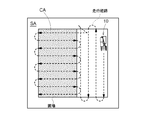
- the peripheral mowing work run hereinafter, simply referred to as peripheral mowing
- an outer peripheral area SA which is a working area (already mowed area)
- an unworked area is formed inside the outer peripheral area SA.
- An inner region CA uncut region
- a traveling route is set in the inner area CA.
- the running path for straight running extends in the horizontal direction of the drawing (# d), or the vertical running extending in the vertical direction of the drawing.
- One of the row path patterns (#e) is adopted. It should be noted that this straight-line running includes not only pure straight-line running but also straight-line running, for example, large curved line running, meandering running, and the like.
- the judgment condition (running route creation condition) for selecting either the horizontal traveling route pattern or the vertical traveling route pattern for the traveling route for straight traveling includes the lodging state of the lodging crop in the inner region CA, especially the lodging direction. included. Therefore, the traveling route is set so that the agricultural work machine 1 travels in the lodging direction of the fallen crop, that is, the cutting is performed.
- FIG. 4 shows an example in which a traveling route set by using a vertical traveling route pattern is changed to a traveling route set by using a horizontal traveling route pattern on the way.
- FIG. 5 shows a functional block diagram of the control system of the agricultural work machine 1.
- the control system of this embodiment is composed of a large number of electronic control units called ECUs, various operating devices, sensor groups and switch groups, and a wiring network such as an in-vehicle LAN that transmits data between them.
- the notification device 84 is a device for notifying the driver or the like of a warning such as an obstacle detection result or a working running state, and is a buzzer, a lamp, a speaker, a display, or the like.
- the control unit 6 is a core element of this control system and is shown as an aggregate of a plurality of ECUs.
- the positioning data from the satellite positioning module 80 and the captured image from the photographing unit 21 are input to the control unit 6 through the wiring network.
- the control unit 6 includes an output processing unit 6B and an input processing unit 6A as input / output interfaces.
- the output processing unit 6B is connected to the vehicle traveling equipment group 7A and the working equipment group 7B.
- the vehicle traveling device group 7A includes control devices related to vehicle traveling, such as an engine control device, a shift control device, a braking control device, and a steering control device.
- the working equipment group 7B includes a harvesting unit 15, a transporting device 16, a threshing device 13, a power control device in the grain discharging device 18, and the like.
- a traveling system detection sensor group 8A, a working system detection sensor group 8B, and the like are connected to the input processing unit 6A.
- the traveling system detection sensor group 8A includes sensors that detect the state of the engine speed adjuster, the accelerator pedal, the brake pedal, the speed change operation tool, and the like.
- the working system detection sensor group 8B includes a sensor for detecting the device state of the harvesting unit 15, the transport device 16, the threshing device 13, and the grain discharging device 18, and the state of crops and grains.
- the control unit 6 includes a travel control module 60, a travel route setting unit 64, an obstacle avoidance command generation unit 65, an aircraft position calculation unit 66, a notification unit 67, a travel locus management unit 68, and a planted crop state detection unit 50. It is equipped. Specifically, the control unit 6 is composed of a computer device having a CPU, a communication function, and a storage function (a drive unit and / or an input / output interface for an internal recording medium and an external recording medium), and a predetermined computer program. To.
- This computer program uses the computer device as a travel control module 60, a travel route setting unit 64, an obstacle avoidance command generation unit 65, an aircraft position calculation unit 66, a notification unit 67, a travel locus management unit 68, and a planted crop state detection. It functions as a unit 50.
- This computer program is recorded on the computer-readable recording medium described above. By executing this computer program, a method including steps corresponding to the above-mentioned functional units is executed in the automatic driving system.
- the aircraft position calculation unit 66 calculates the aircraft position, which is the map coordinates (or field coordinates) of at least one specific location of the aircraft 10, based on the positioning data sequentially sent from the satellite positioning module 80.
- the travel control module 60 is provided with a travel control unit 61, a work control unit 62, and a travel command unit 63.
- a traveling mode switch (not shown) for selecting between an automatic traveling mode in which the vehicle travels by automatic steering and a manual steering mode in which the vehicle travels by manual steering is provided in the driving unit 12. By operating this travel mode switch, it is possible to shift from manual steering running to automatic steering running, or from automatic steering running to manual steering running.
- the travel control unit 61 has an engine control function, a steering control function, a vehicle speed control function, and the like, and gives a travel control signal to the vehicle travel equipment group 7A.
- the work control unit 62 gives a work control signal to the work equipment group 7B via the output processing unit 6B in order to control the movements of the harvesting unit 15, the threshing device 13, the grain discharge device 18, and the like.
- the travel control unit 61 functions as an automatic travel control unit and a manual travel control unit.
- the travel command unit 63 generates a steering command and a vehicle speed command as automatic travel commands and gives them to the travel control unit 61.
- the steering command at the time of automatic driving is generated so as to eliminate the directional deviation and the positional deviation between the traveling route set by the traveling route setting unit 64 and the own aircraft position calculated by the aircraft position calculation unit 66. ..
- the vehicle speed command during automatic driving is generated based on a vehicle speed value set in advance. Steering commands and vehicle speed commands during manual driving are generated based on manual operation.
- the notification unit 67 generates notification data based on a request from each functional unit of the control unit 6 and gives it to the notification device 84.
- the travel locus management unit 68 manages the unworked area and the already worked area in the field based on the aircraft position from the aircraft position calculation unit 66 and the work travel information from the travel control module 60, and the remaining unworked area. Calculate the shape of the area.
- the planted crop status detection unit 50 outputs planted crop status information indicating an abnormal status of the planted crop.
- the abnormal state and the abnormal state of the planted crop are determined based on the image captured by the photographing unit 21, the position of the photographing unit 21 calculated from the position of the machine body, and the shooting angle of view of the photographing unit 21.
- the abnormal state of the planted crop includes a state in which weeds are mixed in the planted crop, a state in which the planted crop is lying down, and a state in which the planted crop is lying down in a specific direction. Obstacles are found in the planted crops, and obstacles are found in the cut marks of the planted crops. The abnormal state of such various planted crops and the position where the abnormal state occurs are included in the planted crop state information.
- the planted crop state detection unit 50 of this embodiment includes an image acquisition unit 51, a machine learning unit 52, a fallen crop detection unit 53, and an obstacle detection unit 54.
- the image acquisition unit 51 stores the photographed image sent from the photographing unit 21 at a predetermined cycle in the memory by linking it with the own machine position calculated by the machine body position calculating unit 66.
- the machine learning unit 52 is constructed by a machine-learned neural network. Since the photographed image acquired by the photographing unit 21 is used as an input image, the abnormal state of the planted crops (including the fallen crops, weeds, and people in the field) included in this photographed image is recognized and output. , A deep learning algorithm with excellent cognitive ability is used.
- the output of the machine learning unit 52 includes a fallen crop area where a fallen crop exists, a weed area where weeds exist, and a person area where a person exists, and recognizes the size of each area and the position in the captured image.
- the result data is output. Such recognition result data can be imaged as shown in FIG.
- the positional relationship between the collapsed crop area, the weed area, and the person area with respect to the aircraft 10 can be calculated.
- epipolar image processing on the captured image acquired over time can be used.
- the recognition result data output from the machine learning unit 52 and the distance to each area are used for various control processes as planted crop state information indicating an abnormal state of the planted crop.
- the fallen crop detection unit 53 extracts data on the fallen crop from the planted crop state information, obtains the position of the fallen crop area in the field and the fall direction of the fallen crop, and outputs it as the fallen crop data.
- the obstacle detection unit 54 extracts data on a person from the planted crop state information, obtains the position of a person area in the field, and outputs it as obstacle data.
- the notification unit 67 also generates information on the detected obstacles and fallen crops based on the obstacle data, and notifies the information through the notification device 84.
- the travel route setting unit 64 has a function of expanding the created travel route for automatic driving in a memory and sequentially setting it as a target travel route in automatic driving. At that time, if the planted crop status information is output from the planted crop status detection unit 50, for example, if the collapsed crop data from the collapsed crop detection unit 53 is output, based on this collapsed crop data, Set or reset the travel route for automatic work travel.
- the travel route setting unit 64 is configured to create and change the travel route based on the planted crop state information.
- the travel route setting unit 64 sets more fallen crops with respect to the inner region CA, which is an unworked region located inside the outer peripheral region SA where the work travel is to be performed.
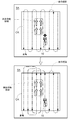
- a travel route is set so that the work can be carried out in a direction close to or after cutting. For example, as shown in FIG. 7, perimeter mowing generally leaves a rectangular inner region CA. Then, for example, for this inner region CA, a traveling route is set so as to connect a plurality of parallel linear routes in a U-turn. At that time, the traveling route is set so as to be a follow-up for the fallen crop based on the fallen crop area and the fall direction (indicated by the arrow in the fallen crop area in FIG. 7). This improves the efficiency of harvesting work in the fallen crop area.
- the traveling route setting unit 64 does not use the traveling route set in advance as the target traveling route, and the lodging crop A new target driving route is set, which is a follow-up or almost a follow-up.
- the target traveling route on the previously set traveling route does not result in additional cutting for the fallen crop area detected in the middle of central cutting, at that time.
- the target travel route is changed, and a new target travel route is set, which is a follow-up or almost a follow-up. This improves the efficiency of harvesting work in the fallen crop area.
- the target travel route may be set so that the travel route setting unit 64 travels the agricultural work machine 1 in a direction intersecting the direction of the lodging of the crop.
- the traveling route is set so that the traveling route is orthogonal to the direction of the crop lodging (indicated by the arrow) in the collapsed crop area. This improves the efficiency of harvesting work in the fallen crop area.
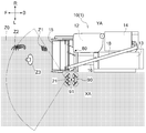
- the traveling route is set so that the fallen crop is in a state of falling toward the unworked area XA when viewed from the machine 10 of the agricultural work machine 1.
- the work running is performed so that the left side of the machine body 10 is the unworked area XA and the right side of the machine body 10 is the already worked area YA.
- the traveling route is set by the traveling route setting unit 64 so that the lying down crop is tilted to the left when viewed from the machine body 10.
- the harvesting run in which the left side of the machine body 10 is the unworked area XA is often performed when the driving unit 12 is located on the right side portion of the machine body 10.
- the optimum travel route is set for such the abnormal state.
- a travel route is set to avoid such anomalous areas.
- the obstacle avoidance command generation unit 65 generates an obstacle avoidance command including vehicle speed change including forced stop, engine stop, turning running, etc. based on obstacle data from the obstacle detection unit 54, and travels. It is given to the control module 60.
- the components constituting the traveling control module 60 and the planted crop state detection unit 50 shown in FIG. 5 are mainly separated for the purpose of explanation, and the integration of the components and the division of the components are not performed. , May be done freely.
- the photographing unit 21 is attached to the front end of the grain discharging device 18, but may be attached to another portion. Further, the plurality of photographing units 21 may be attached to different parts. Since it is important to monitor the front in the traveling direction, the photographing unit 21 may be provided on the front portion of the combine, for example, the front end portion of the roof portion of the driving unit 12.
- the machine learning unit 52 is composed of a neural network machine-learned by using a deep learning algorithm.
- the machine learning unit 52 may be configured by a neural network using an algorithm other than the deep learning algorithm, for example, a recurrent neural network. Further, an image recognition technique other than the machine-learned neural network may be adopted for the machine learning unit 52.
- a part of the components of the automatic traveling system may be provided outside the agricultural work machine 1.
- the functional units of the control unit 6 may be provided in a control device (computer device) provided outside the agricultural work machine 1.
- the agricultural work machine 1 is not limited to the ordinary combine harvester.
- the farm work machine 1 may be a head-feeding combine.
- the agricultural work machine 1 may be a corn harvester.
- FIG. 11 shows a corn harvester which is an agricultural work machine 1.
- the header (harvesting section) of the ordinary combine is replaced with the pre-harvest processing apparatus 115.
- This corn harvester separates tufts from the corn to be planted, separates grains from tufts, and stores the grains.
- This corn harvester includes a crawler type traveling device (not shown), an operating unit 112, a threshing device 113, a grain tank 114, a harvesting pretreatment device 115 as a working unit, a transport device 116, a grain discharging device 118, and a satellite. It includes components such as a positioning module 180.
- the body 110 of the corn harvester means a collection of components, but in some cases may mean individual components such as a traveling device or a pre-harvesting device 115.
- the pre-harvest treatment device 115 separates the tufts from the corn to be planted and sends the tufts to the transport device 116.
- the threshing device 113 separates the grains from the tufts transported by the transport device 116.
- An imaging unit 121 is provided on the front wall surface of the discharge unit of the grain discharge device 118.
- the automatic traveling system includes the control unit 6 and causes the agricultural work machine 1 to execute the same automatic traveling as in the above-described embodiment.
- FIG. 12 shows another form of corn harvester. This corn harvester separates tufts from the corn to be planted, removes the bracts from the tufts, and stores the tufts.
- This corn harvester has components such as a wheel-type traveling device (not shown), a driving unit 212, a leaflet removing unit 213, a storage tank 214, a harvesting unit 215 as a working unit, a transport device 216, and a satellite positioning module 280. It has.
- the body 210 of the corn harvester means a collection of components, but in some cases, it may mean individual components such as a traveling device and a harvesting unit 215.
- the harvesting unit 215 separates the tufts from the corn to be planted and sends the tufts to the transport device 216.
- the bract removing unit 213 removes the bracts from the tufts transported by the transport device 216.
- a photographing unit 221 is provided above the driving unit 212.
- the automatic traveling system according to the present embodiment includes the control unit 6 and causes the agricultural work machine 1 to execute the same automatic traveling as in the above-described embodiment.
- the agricultural work machine 1 may be a sugar cane harvester.
- FIG. 13 shows a sugar cane harvester as an example of an agricultural work machine. This sugar cane harvester harvests the sugar cane to be planted, separates the sugar cane from impurities, and discharges the sugar cane to the rear of the machine.
- This sugar cane harvester is equipped with components such as a wheel-type traveling device 311, a driving unit 312, a separating device 313, a harvesting unit 315 as a working unit, a transport device 316, a discharge device 318, and a satellite positioning module 380.
- the body 310 of the sugar cane harvester means a collection of components, but in some cases, it may mean individual components such as a traveling device 311 and a harvesting unit 315.
- the harvesting unit 315 cuts the sugar cane to be planted and sends the sugar cane to the transport device 316.
- the separation device 313 separates impurities from the sugar cane transported by the transfer device 316.
- the discharge device 318 discharges sugar cane separated from impurities by the separation device 313 to the rear of the machine body 310.
- An imaging unit 321 is provided above the driving unit 312.
- the automatic traveling system according to the present embodiment includes the control unit 6 and causes the agricultural work machine 1 to execute the same automatic traveling as in the above-described embodiment.
- the agricultural work machine 1 may be a passenger type management machine.
- FIG. 14 shows a passenger-type management machine as an example of an agricultural work machine. This passenger-type management machine performs spraying work of spraying chemicals (agricultural chemicals, fertilizers, etc.) on planted crops while traveling in the field.
- spraying chemicals agricultural chemicals, fertilizers, etc.
- This passenger-type management machine includes components such as a traveling wheel 411 (wheel-type traveling device), a driving unit 412, a chemical spraying unit 415 as a working unit, a chemical tank 425, a broadcaster 426, and a satellite positioning module 480.
- the body 410 of the passenger-type management machine means a collection of components, but in some cases, it may mean individual components such as a traveling wheel 411 and a chemical spraying unit 415.
- the drug spraying unit 415 sprays the drug stored in the drug tank 425 to the field.
- the chemical spraying portion 415 includes a center boom 415D and left and right side booms 415E.
- An imaging unit 421 is provided above the driving unit 412.
- the automatic traveling system according to the present embodiment includes the control unit 6 and causes the agricultural work machine 1 to execute the same automatic traveling as in the above-described embodiment.
- the automatic traveling system of the present embodiment includes a photographing unit 90 (an example of a moving body) that can move independently of the agricultural work machine 1.
- the photographing unit 21 is provided in the photographing unit 90.
- the photographing unit 90 is a flying object that can be moved by flight, and is a so-called drone.
- the photographing unit 90 includes a satellite positioning module 91.
- FIG. 16 shows a functional block diagram of the control system of the automatic driving system of the present embodiment.
- the main components of this control system are a control unit 6 mounted on the agricultural work machine 1 and a control unit 92 mounted on the photographing unit 90.
- the control unit 6 of the agricultural work machine 1 has the same configuration and function as the illustrated example of FIG.
- the agricultural work machine 1 is provided with a communication unit 85 capable of communicating with the photographing unit 90 via the communication network N.
- the communication unit 85 is connected to the control unit 6.
- the control unit 92 controls the operation of the photographing unit 90.
- the control unit 92 includes a computer device and a predetermined computer program.
- the photographing unit 90 is provided with a communication unit 93 capable of communicating with the agricultural work machine 1 via the communication network N.
- the communication unit 93 is connected to the control unit 92.
- the control unit 92 controls the movement (flight) of the photographing unit 90.
- the control unit 92 controls the flight of the photographing unit 90 so that the photographing unit 90 is located at a predetermined position with respect to the agricultural work machine 1 (for example, the upper left side of the agricultural work machine 1).
- the control unit 92 calculates the position of the moving body, which is the map coordinates (or field coordinates) of at least one specific location of the photographing unit 90, based on the positioning data sequentially sent from the satellite positioning module 91.
- the moving body position includes information indicating the orientation of the photographing unit 90, that is, the orientation (angle of view) of the photographing unit 21.
- the control unit 92 transmits the captured image sent from the photographing unit 21 at a predetermined cycle and the calculated moving body position to the control unit 6 of the agricultural work machine 1 in a state of being linked to each other. Then, the image acquisition unit 51 of the control unit 6 of the agricultural work machine 1 acquires the photographed image transmitted from the photographing unit 90 via the communication unit 85 and stores it in the memory.
- the planted crop state detection unit 50 generates and outputs planted crop state information.
- the photographing unit 90 may be a vehicle, a balloon, a self-propelled robot, or the like.
- the photographing unit 90 is a device that can move by itself. It is also possible that the photographing unit 90 does not have a moving function.
- the photographing unit 90 may be a stationary device installed around the field. The device may be permanently installed or temporarily installed. In this case, the photographing unit 21 is arranged around the field in a state independent of the agricultural work machine 1.
- the photographing unit 90 may be portable by the operator.
- the photographing unit 90 may be a mobile information terminal such as a smartphone.
- the image captured by the photographing unit 21 is transmitted from the photographing unit 90 to the agricultural work machine 1 via the communication network N.
- the image may be transmitted via a mobile information terminal (smartphone or the like) held by the operator. Specifically, the image may be first transmitted from the photographing unit 90 to the mobile information terminal, and then transmitted from the mobile information terminal to the agricultural work machine 1.
- the image may be transmitted via another computer, a server, an agricultural information management system, or the like. Specifically, the image may be first transmitted from the photographing unit 90 to the server or the like, and then transmitted from the server to the agricultural work machine 1. Further, the image may be first transmitted from the photographing unit 90 to the server or the like, then transmitted from the server to the operator's mobile information terminal, and then transmitted from the mobile information terminal to the agricultural work machine 1.
- the agricultural work machine 1 includes the control unit 6 shown in FIG.
- the image acquisition unit 51 acquires an image of the field taken from another computer, server, agricultural information management system, or the like via the communication unit 85, and stores it in the memory.
- the image acquired by the image acquisition unit 51 is an image taken in advance and stored in a server or the like.
- the image may be taken by a camera of a mobile information terminal, may be taken by a camera mounted on a drone, a passenger-type management machine, or the like, or may be taken by an artificial satellite camera. It may be a captured image (so-called satellite image).
- the satellite image may be transmitted directly from the artificial satellite to the agricultural work machine 1.
- the planted crop state detection unit 50 analyzes the image of the field and generates and outputs the planted crop state information.
- the generation of planted crop status information may be performed based on an artificial operation from the operator.
- FIG. 17 shows a functional block diagram of the control system of the automatic driving system of the present embodiment.
- the control unit 6 of the agricultural work machine 1 has the same configuration and function as the illustrated example of FIG.
- the control unit 6 includes an information output unit 550 in place of the planted crop state detection unit 50.
- the agricultural work machine 1 is provided with a display input device 86 (an example of an operation unit) that accepts an artificial operation instead of the photographing unit 21.
- the display input device 86 is, for example, a liquid crystal touch panel device.
- the information output unit 550 identifies the abnormal state of the planted crop and the position where the abnormal state occurs based on the artificial operation received by the display input device 86, and outputs the planted crop state information based on the specific result. Output. Specifically, the control unit 6 displays a map of the field on the display input device 86 and waits for an artificial operation from the operator. The operator operates the display input device 86 to input an abnormal state of the planted crop (for example, a state of lodging of the crop) and a position where the abnormal state occurs. The information output unit 550 generates and outputs planted crop state information based on the artificial operation received by the display input device 86.
- the present invention is applicable to an automatic traveling system for agricultural work machines, agricultural work machines, programs, recording media on which programs are recorded, and methods.
- Agricultural work machine 15 Harvesting department (working department) 21: Photographing unit 50: Planted crop condition detection unit (information output unit) 61: Travel control unit (automatic travel control unit) 64: Travel route setting unit 66: Aircraft position calculation unit 80: Satellite positioning module 86: Display input device (operation unit) 90: Mobile 115: Pre-harvest treatment device (working unit) 121: Imaging unit 180: Satellite positioning module 215: Harvesting unit (working unit) 221: Imaging unit 280: Satellite positioning module 310: Aircraft 315: Harvesting unit (working unit) 321 : Imaging unit 380 : Satellite positioning module 415 : Chemical spraying unit (working unit) 421: Imaging unit 480: Satellite positioning module 550: Information output unit CA: Inner area SA: Outer peripheral area
Landscapes
- Life Sciences & Earth Sciences (AREA)
- Environmental Sciences (AREA)
- Engineering & Computer Science (AREA)
- Automation & Control Theory (AREA)
- Physics & Mathematics (AREA)
- General Physics & Mathematics (AREA)
- Remote Sensing (AREA)
- Radar, Positioning & Navigation (AREA)
- Mechanical Engineering (AREA)
- Soil Sciences (AREA)
- Aviation & Aerospace Engineering (AREA)
- Guiding Agricultural Machines (AREA)
- Combines (AREA)
- Control Of Position, Course, Altitude, Or Attitude Of Moving Bodies (AREA)
Abstract
自動走行システムは、圃場の植立作物に対して作業を行う作業部を備え圃場で作業走行を行う農作業機と、衛星測位モジュール80からの測位データに基づいて農作業機の機体位置を算出する機体位置算出部66と、機体位置を用いて農作業機を自動走行させる自動走行制御部61と、植立作物の異常状態を示す植立作物状態情報を出力する情報出力部50と、植立作物状態情報に基づいて、農作業機が行う自動作業走行のための走行経路を設定する走行経路設定部64と、を備える。
Description
本発明は、自動走行システム、農作業機、プログラム、プログラムを記録した記録媒体、及び方法に関する。
収穫時期の植立穀稈は、正常である直立状態だけでなく、倒伏状態や雑草混在状態などの異常な状態となる場合がある。特許文献1に記載された収穫機では、植立穀稈の状態に応じた装置の制御が行われる。詳しくは、この収穫機には、刈取部の前方の穀稈を撮影するテレビカメラと画像処理装置とが備えられている。画像処理装置は、テレビカメラからの画像と、予め記憶させておいた種々の穀稈の植立状態を示す画像とを比較して、穀稈の植立状態を検出する。刈取部前方の穀稈の一部が倒伏していることが検出されると、倒伏穀稈に対する刈取性能を向上させるために、走行速度を減速すると共に、掻込みリールが下方に移動する。
特許文献2による収穫機では、深層学習を採用したニューラルネットワーク技術を用いて構築された画像認識モジュールによって、倒伏穀稈の存在が推定される。更に、衛星測位によって算出される機体位置に基づいて、倒伏穀稈の地図上の位置も求められる。その結果、地図上における倒伏穀稈領域の分布と、地図上における農作物の作物評価値の分布とを対比することで、次回の農作において、倒伏穀稈領域に対する施肥量を低減させたり、植付け量を調整したりすることも可能となる。
植立穀稈が異常状態にある場合、農作業機の走行経路を工夫することによりメリットが生じる可能性がある。例えば、植立穀稈が倒伏状態にある場合、穀稈の倒伏方向と農作業機(収穫機)の進行方向との関係を適切にすることにより、作業効率を向上できる可能性がある。例えば、植立穀稈が雑草混在状態にある場合、雑草が存在する領域を避けることにより、収穫物への雑草の混入(収穫機の場合)や、雑草への施肥(管理機の場合)を抑制できる可能性がある。
特許文献1による倒伏穀稈検出技術では、予め記憶させておいた種々の穀稈の植立状態を示す画像とカメラからの撮影画像とを比較することで、撮影画像に倒伏穀稈が含まれているかどうかが判定される。この技術では、植立穀稈が倒伏しているか否かだけが推定され、倒伏方向は推定することができない。また、特許文献1において、穀稈の植立状態に応じた農作業機の走行経路の設定や変更は、開示も示唆もされていない。
特許文献2による倒伏穀稈検出技術では、近年、画像認識において大きな成果を出している深層学習を採用したニューラルネットワーク技術が用いられているので、種々の穀稈の植立状態の検出が可能となる。しかし、特許文献2においても、穀稈の植立状態に応じた農作業機の走行経路の設定や変更は、開示も示唆もされていない。
上記実情に鑑みて、本発明の課題は、植立作物の異常状態に応じて走行経路を設定し、農作業機に自動作業走行を行わせることが可能なシステムを提供することである。
本発明による自動走行システムは、圃場の植立作物に対して作業を行う作業部を備え圃場で作業走行を行う農作業機と、衛星測位モジュールからの測位データに基づいて前記農作業機の機体位置を算出する機体位置算出部と、前記機体位置を用いて前記農作業機を自動走行させる自動走行制御部と、前記植立作物の異常状態を示す植立作物状態情報を出力する情報出力部と、前記植立作物状態情報に基づいて、前記農作業機が行う自動作業走行のための走行経路を設定する走行経路設定部と、を備える。
この構成によれば、情報出力部から出力された植立作物状態情報に基づいて、自動作業走行のための走行経路が設定されるので、植立作物の異常状態に適した走行経路で農作業機が作業走行を行うことができる。植立作物の異常状態の種別と、当該種別に適した走行経路(あるいは、走行経路の決定方法)を予め決めて、走行経路設定部に登録しておくとよい。なお、ここでの走行経路に関して、一方方向の走行経路と他方方向の走行経路とが別のものとして取り扱われている。
本発明の好適な実施形態の1つでは、前記情報出力部は、前記植立作物を撮影した撮影画像に基づいて前記植立作物の異常状態と当該異常状態が発生している位置とを検知し、検知結果に基づいて前記植立作物状態情報を出力する。
この構成によれば、撮影画像に基づいて異常状態が発生している位置が検知されるので、農作業機の走行経路が適切に設定されて、異常状態となっている植立作物にとって適切な走行経路で作業走行を行うことができる。
本発明の好適な実施形態の1つでは、自動走行システムは、前記植立作物を撮影する撮影部を備え、前記情報出力部は、前記撮影部による撮影画像と、前記撮影部の位置と、前記撮影部の画角と、に基づいて前記植立作物の異常状態と当該異常状態が発生している位置とを検知し、検知結果に基づいて前記植立作物状態情報を出力する。
この構成によれば、撮影部の位置(撮影中心位置)と撮影画角とから、撮影画像に含まれる圃場領域が算出できるので、当該撮影画像から情報出力部が植立作物の異常状態と撮影画像における異常状態が発生している位置とを検知した場合、異常状態が発生している位置と農作業機との位置関係も算出できる。この推定結果に基づいて、走行経路を設定することで、異常状態となっている植立作物にとって適切な走行経路で作業走行を行うことができる。
本発明の好適な実施形態の1つでは、前記撮影部が前記農作業機に設けられている。
この構成によれば、撮影部が農作業機に設けられているので、農作業機を走行させながら圃場の撮影画像を取得することができる。これにより、異常状態を適切に検出し、異常状態となっている植立作物にとって適切な走行経路で作業走行を行うことができる。
植立作物に対する作業(例えば、収穫作業)を困難にする植立作物の異常状態の一つは、植立作物が倒伏している状態である。例えば、倒伏した植立作物(倒伏作物)の収穫に関しては、収穫走行の方向を適切に選択する方法、収穫走行の最後に行う方法、機械刈りを諦めて手刈りを用いる方法などがあるので、適切に倒伏作物の位置を知ることが重要である。このことから、本発明の好適な実施形態の1つでは、前記情報出力部は、前記異常状態として前記植立作物が倒伏状態である倒伏作物を検知するように構成されている。
植立作物の異常状態が倒伏作物であり、その倒伏作物の倒伏方向がある程度揃っている場合には、倒伏作物に対する適切な収穫方向(追い刈りが適切である)が知られている。このことから、本発明の好適な実施形態の1つでは、前記情報出力部は、前記倒伏作物の倒伏方向を検知するように構成されている。
植立作物状態情報に基づいて自動作業走行のための走行経路が設定されるので、植立作物が異常状態であっても、その異常状態に応じて適正な作業走行を行うことができる。詳しくは、次の2つの方法が好適である。
(1)圃場に対する作業走行において、常時、情報出力部による植立作物の異常状態がチェックされる。異常状態が検知されると、その異常状態が発生している領域を適正な方向で走行するために、予め設定されている走行経路を変更する。この(1)の方法を実践するために、本発明の好適な実施形態の1つでは、前記情報出力部は、前記作業走行中に前記撮影部よって取得された前記撮影画像を用いて前記植立作物状態情報を出力し、前記走行経路設定部は、前記植立作物状態情報に基づいて、次の目標となる走行経路(目標走行経路)を決定する。
(2)圃場の収穫作業は、最初に行われる周囲刈りと、その後に行われる中央刈りとによって行われる。周囲刈りでは、圃場の外周領域を手動で(自動であってもよい)作業走行を行う。中央刈りでは、外周領域の内側に位置する内側領域に対して自動走行のための走行経路が算出され、この走行経路に沿って農作業機は自動で作業走行を行う。最初に行われる周囲刈りの際に、情報出力部によって内側領域の植立作物状態情報の作成が可能となる。したがって、周囲刈りが終了すると、内側領域のための走行経路が植立作物状態を考慮して設定することができる。この(2)の方法を実践するために、本発明の好適な実施形態の1つでは、前記情報出力部は、前記圃場の外周領域の植立作物を刈り取る周囲刈り作業走行において前記撮影部よって取得された前記撮影画像を用いて前記植立作物状態情報を出力し、前記走行経路設定部は、前記植立作物状態情報を走行経路作成条件として、前記外周領域の内側に位置する内側領域の前記自動作業走行のための走行経路を算出する。
本発明の好適な実施形態の1つでは、自動走行システムは、前記農作業機から独立して移動可能な移動体を備え、前記撮影部が前記移動体に設けられている。
この構成によれば、農作業機の位置に制約されずに撮影部が撮影を行うことが可能となる。これにより、異常状態を適切に検出し、異常状態となっている植立作物にとって適切な走行経路で作業走行を行うことができる。
本発明の好適な実施形態の1つでは、前記撮影部が、前記農作業機から独立した状態で圃場周辺に配置される。
この構成によれば、農作業機の位置に制約されずに撮影部が撮影を行うことが可能となる。これにより、異常状態を適切に検出し、異常状態となっている植立作物にとって適切な走行経路で作業走行を行うことができる。
本発明の好適な実施形態の1つでは、前記情報出力部は、前記撮影画像を入力画像として植立作物の前記異常状態を出力する、機械学習されたニューラルネットワークを含んでいる。
この構成によれば、異常状態を更に適切に検出し、異常状態となっている植立作物にとって適切な走行経路で作業走行を行うことができる。
本発明の好適な実施形態の1つでは、自動走行システムは、人為操作を受け付ける操作部を備え、前記情報出力部は、前記操作部が受け付けた人為操作に基づいて前記植立作物の異常状態と当該異常状態が発生している位置とを特定し、特定結果に基づいて前記植立作物状態情報を出力する。
この構成によれば、人為操作に基づいて植立作物の異常状態及び位置を確実に特定し、異常状態となっている植立作物にとって適切な走行経路で作業走行を行うことができる。
また、本発明による農作業機は、圃場の植立作物に対して作業を行う作業部と、衛星測位モジュールからの測位データに基づいて機体位置を算出する機体位置算出部と、前記機体位置を用いて機体を自動走行させる自動走行制御部と、前記植立作物の異常状態を示す植立作物状態情報を出力する情報出力部と、前記植立作物状態情報に基づいて、自動作業走行のための走行経路を設定する走行経路設定部と、を備える。
また、本発明によるプログラムは、圃場の植立作物に対して作業を行う作業部と衛星測位モジュールとを備える農作業機に自動作業走行を行わせる自動走行システムのためのプログラムであって、前記衛星測位モジュールからの測位データに基づいて前記農作業機の機体位置を算出する機体位置算出機能と、前記機体位置を用いて前記農作業機を自動走行させる自動走行制御機能と、前記植立作物の異常状態を示す植立作物状態情報を出力する情報出力機能と、前記植立作物状態情報に基づいて、前記農作業機が行う自動作業走行のための走行経路を設定する走行経路設定機能と、をコンピュータに実現させる。
また、本発明によるプログラムを記録した記録媒体は、圃場の植立作物に対して作業を行う作業部と衛星測位モジュールとを備える農作業機に自動作業走行を行わせる自動走行システムのためのプログラムを記録した記録媒体であって、前記衛星測位モジュールからの測位データに基づいて前記農作業機の機体位置を算出する機体位置算出機能と、前記機体位置を用いて前記農作業機を自動走行させる自動走行制御機能と、前記植立作物の異常状態を示す植立作物状態情報を出力する情報出力機能と、前記植立作物状態情報に基づいて、前記農作業機が行う自動作業走行のための走行経路を設定する走行経路設定機能と、をコンピュータに実現させるプログラムを記録している。
また、本発明による方法は、圃場の植立作物に対して作業を行う作業部と衛星測位モジュールとを備える農作業機に自動作業走行を行わせる方法であって、前記衛星測位モジュールからの測位データに基づいて前記農作業機の機体位置を算出する機体位置算出ステップと、前記機体位置を用いて前記農作業機を自動走行させる自動走行制御ステップと、前記植立作物の異常状態を示す植立作物状態情報を出力する情報出力ステップと、前記植立作物状態情報に基づいて、前記農作業機が行う自動作業走行のための走行経路を設定する走行経路設定ステップと、を含んでいる。
〔第1実施形態〕
本発明に係る自動走行システムの実施形態が、図面に基づいて以下説明される。自動走行システムは、圃場の植立作物に対して作業を行う収穫部15(作業部の一例)を備え圃場で作業走行を行う農作業機1と、衛星測位モジュール80からの測位データに基づいて農作業機1の機体位置を算出する機体位置算出部66(図5)と、機体位置を用いて農作業機1を自動走行させる走行制御部61(自動走行制御部の一例)と、植立作物の異常状態を示す植立作物状態情報を出力する植立作物状態検知ユニット50(情報出力部の一例)と、植立作物状態情報に基づいて、農作業機1が行う自動作業走行のための走行経路を設定する走行経路設定部64と、を備える。本実施形態では、自動走行システムの構成要素は、全て農作業機1に搭載されている。農作業機1は、収穫機である普通型コンバインである。なお、特に断りがない限り、図1及び図2に示す矢印Fの方向を「前」、矢印Bの方向を「後」とする。また、図2に示す矢印Lの方向を「左」、矢印Rの方向を「右」とする。また、図1に示す矢印Uの方向を「上」、矢印Dの方向を「下」とする。
本発明に係る自動走行システムの実施形態が、図面に基づいて以下説明される。自動走行システムは、圃場の植立作物に対して作業を行う収穫部15(作業部の一例)を備え圃場で作業走行を行う農作業機1と、衛星測位モジュール80からの測位データに基づいて農作業機1の機体位置を算出する機体位置算出部66(図5)と、機体位置を用いて農作業機1を自動走行させる走行制御部61(自動走行制御部の一例)と、植立作物の異常状態を示す植立作物状態情報を出力する植立作物状態検知ユニット50(情報出力部の一例)と、植立作物状態情報に基づいて、農作業機1が行う自動作業走行のための走行経路を設定する走行経路設定部64と、を備える。本実施形態では、自動走行システムの構成要素は、全て農作業機1に搭載されている。農作業機1は、収穫機である普通型コンバインである。なお、特に断りがない限り、図1及び図2に示す矢印Fの方向を「前」、矢印Bの方向を「後」とする。また、図2に示す矢印Lの方向を「左」、矢印Rの方向を「右」とする。また、図1に示す矢印Uの方向を「上」、矢印Dの方向を「下」とする。
図1及び図2に示されるように、農作業機1は、クローラ式の走行装置11、運転部12、脱穀装置13、穀粒タンク14、収穫部15、搬送装置16、穀粒排出装置18、衛星測位モジュール80を備えている。農作業機1の機体10は、農作業機1の主な構成要素、例えば運転部12、脱穀装置13、穀粒タンク14などの集合体を意味する。
走行装置11は、エンジン(図示せず)からの動力によって駆動されるものであっても、電動モータで駆動されるものであってもよい。
運転部12には、農作業機1の作業を監視するオペレータが搭乗可能である。なお、オペレータは、農作業機1の機外から農作業機1の作業を監視していてもよい。
収穫部15は機体10の前部に支持されている。搬送装置16は収穫部15よりも後側に隣接して設けられている。収穫部15は圃場の植立作物を収穫する。植立作物は、例えば稲等の植立穀稈であるが、大豆やトウモロコシ等であってもよい。この構成により、農作業機1は、走行しながら圃場の作物を収穫する。そして、農作業機1は、収穫部15によって圃場の作物を収穫しながら走行装置11によって走行する作業走行が可能である。
収穫部15によって刈り取られた植立作物は刈取作物として、搬送装置16によって脱穀装置13へ搬送される。刈取作物は脱穀装置13によって脱穀処理される。脱穀処理により得られた収穫物としての穀粒は、穀粒タンク14に貯留される。穀粒タンク14に貯留された穀粒は、必要に応じて、穀粒排出装置18によって機外に排出される。穀粒排出装置18は機体後部の縦軸芯回りに揺動可能に構成されている。即ち、穀粒排出装置18の排出部が機体10よりも機体横外側へ張り出して作物を排出可能な排出状態と、穀粒排出装置18の排出部が機体10の機体横幅の範囲内に位置する収納状態と、に切換可能なように穀粒排出装置18は構成されている。穀粒排出装置18が収納状態である場合、穀粒排出装置18の排出口部は運転部12よりも前側に位置すると共に収穫部15の上方に位置する。
衛星測位モジュール80が、運転部12のルーフ部前部における機体左右中央側端部に取り付けられている。衛星測位モジュール80は、人工衛星GSからのGNSS(Global Navigation Satellite System)の信号(GPS信号を含む)を受信して、機体位置を取得する。なお、衛星測位モジュール80による衛星航法を補完するために、ジャイロ加速度センサや磁気方位センサを組み込んだ慣性航法ユニットが衛星測位モジュール80に組み込まれている。もちろん、慣性航法ユニットは、農作業機1において衛星測位モジュール80と別の箇所に配置されてもよい。
穀粒排出装置18の排出部の前壁面に撮影部21が設けられている。撮影部21は、広角レンズを装着したカラーカメラであって、例えばCCDカメラやCMOSカメラである。穀粒排出装置18が収納状態の場合、撮影部21は、農作業機1の前進方向の前方を、当該穀粒排出口の箇所から前下方の向きで撮像可能に構成されている。このとき、撮影部21は運転部12よりも前側に位置し、撮影部21の前後方向が前下がりに傾斜する状態で穀粒排出装置18の排出部に支持される。これにより、撮影部21は、収穫部15の前端領域における植立作物の状態を近距離で撮像できる。また、この撮影部21は、圃場に存在する植立作物及び植立作物の刈り跡だけでなく、その他の圃場に存在する物体、例えば、雑草や人物なども撮影可能である。図1及び図2では、符号Z0で示された正常な植立作物群、符号Z1で示された雑草群、符号Z2で示された倒伏作物群、符号Z3で示された人物が模式的に示されている。
この実施形態の農作業機1は自動走行と手動走行との両方で走行可能である。自動走行では、農作業機1は、圃場に設定される走行経路に沿って自動的に作業走行する。図3には、圃場における標準的な収穫作業の一例が示されている。ここでは、農作業機1が圃場に入ると(#a)、周囲刈り作業走行(以下単に周囲刈りと称する)が行われる(#b)。何周かの周囲刈りが手動又は自動で行われると、この圃場の外周に既作業領域(既刈領域)である外周領域SAが形成されると共に、外周領域SAの内側には、未作業領域(未刈領域)である内側領域CAが形成される(#c)。次に、内側領域CAである未作業領域(未刈領域)に対して中央刈り作業走行(以下単に中央刈りと称する)を自動で行うために、内側領域CAに走行経路が設定される。この中央刈りに直線走行とUターン走行とを組み合わせた往復走行が用いられる場合、直線走行のための走行経路が図面横方向に延びる横走行経路パターン(#d)、又は図面縦方向に延びる縦走行経路パターン(#e)のいずれかが採用される。なお、この直線走行には、純然たる直線走行だけでなく、直線状の走行、例えば、大きな湾曲線走行、蛇行走行なども含まれている。直線走行のための走行経路は横走行経路パターン又は縦走行経路パターンのいずれかを選択するための判定条件(走行経路作成条件)には、内側領域CAの倒伏作物の倒伏状態、特に倒伏方向が含まれる。したがって、農作業機1が倒伏作物の倒伏方向に向かって走行するように、つまり追い刈りとなるように、走行経路が設定される。
中央刈りの途中で、他の走行経路パターンを用いた走行経路に変更することも可能である。図4では、縦走行経路パターンを用いて設定された走行経路から、途中で、横走行経路パターンを用いて設定された走行経路に変更される例が示されている。
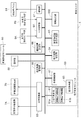
図5には、農作業機1の制御系の機能ブロック図が示されている。この実施形態の制御系は、多数のECUと呼ばれる電子制御ユニットと、各種動作機器、センサ群やスイッチ群、それらの間のデータ伝送を行う車載LANなどの配線網から構成されている。報知デバイス84は、運転者等に障害物の検出結果や作業走行の状態などの警告を報知するためのデバイスであり、ブザー、ランプ、スピーカ、ディスプレイなどである。
制御ユニット6は、この制御系の中核要素であり、複数のECUの集合体として示されている。衛星測位モジュール80からの測位データや撮影部21からの撮影画像は、配線網を通じて制御ユニット6に入力される。
制御ユニット6は、入出力インタフェースとして、出力処理部6Bと入力処理部6Aとを備えている。出力処理部6Bは、車両走行機器群7A及び作業装置機器群7Bと接続している。車両走行機器群7Aには、車両走行に関する制御機器、例えばエンジン制御機器、変速制御機器、制動制御機器、操舵制御機器などが含まれている。作業装置機器群7Bには、収穫部15、搬送装置16、脱穀装置13、穀粒排出装置18における動力制御機器などが含まれている。入力処理部6Aには、走行系検出センサ群8Aや作業系検出センサ群8Bなどが接続されている。走行系検出センサ群8Aには、エンジン回転数調整具、アクセルペダル、ブレーキペダル、変速操作具などの状態を検出するセンサが含まれている。作業系検出センサ群8Bには、収穫部15、搬送装置16、脱穀装置13、穀粒排出装置18における装置状態及び作物や穀粒の状態を検出するセンサが含まれている。
制御ユニット6には、走行制御モジュール60、走行経路設定部64、障害物回避指令生成部65、機体位置算出部66、報知部67、走行軌跡管理部68、及び植立作物状態検知ユニット50が備えられている。具体的には、制御ユニット6は、CPU、通信機能、及びストレージ機能(内部記録媒体並びに外部記録媒体に対するドライブユニット及び/又は入出力インタフェース)を備えたコンピュータ装置と、所定のコンピュータプログラムとで構成される。このコンピュータプログラムは、コンピュータ装置を、走行制御モジュール60、走行経路設定部64、障害物回避指令生成部65、機体位置算出部66、報知部67、走行軌跡管理部68、及び植立作物状態検知ユニット50として機能させる。このコンピュータプログラムは、コンピュータが読み取り可能な上述の記録媒体に記録されている。このコンピュータプログラムを実行することにより、自動走行システムにおいて、上述の各機能部に対応するステップを含む方法が実行される。
機体位置算出部66は、衛星測位モジュール80から逐次送られてくる測位データに基づいて、機体10の少なくとも1つの特定箇所の地図座標(又は圃場座標)である機体位置を算出する。
走行制御モジュール60には、走行制御部61と作業制御部62と走行指令部63とが備えられている。自動操舵で走行する自動走行モードと、手動操舵で走行する手動操舵モードとのいずれかを選択する走行モードスイッチ(非図示)が運転部12内に設けられている。この走行モードスイッチを操作することで、手動操舵走行から自動操舵走行への移行、あるいは自動操舵走行から手動操舵走行への移行が可能である。
走行制御部61は、エンジン制御機能、操舵制御機能、車速制御機能などを有し、車両走行機器群7Aに走行制御信号を与える。作業制御部62は、収穫部15、脱穀装置13、穀粒排出装置18などの動きを制御するために、出力処理部6Bを介して作業装置機器群7Bに作業制御信号を与える。走行制御部61は、自動走行制御部及び手動走行制御部として機能する。
走行指令部63は、自動走行指令として、操舵指令及び車速指令を生成して、走行制御部61に与える。自動走行時の操舵指令は、走行経路設定部64によって設定された走行経路と、機体位置算出部66によって算出された自機位置との間の方位ずれ及び位置ずれを解消するように生成される。自動走行時の車速指令は、前もって設定されている車速値に基づいて生成される。手動走行時の操舵指令や車速指令は、手動操作に基づいて生成される。
報知部67は、制御ユニット6の各機能部からの要求に基づいて報知データを生成し、報知デバイス84に与える。
走行軌跡管理部68は、機体位置算出部66からの機体位置及び走行制御モジュール60からの作業走行情報に基づいて、圃場における未作業領域と既作業領域とを管理し、残されている未作業領域の形状を算出する。
植立作物状態検知ユニット50は、植立作物の異常状態を示す植立作物状態情報を出力する。なお、この実施形態では、撮影部21による撮影画像と、機体位置から算出される撮影部21の位置と、撮影部21の撮影画角とに基づいて、植立作物の異常状態と異常状態が発生している位置とを含む植立作物状態情報を出力する。なお、この実施形態では、植立作物の異常状態には、植立作物に雑草が紛れている状態、植立作物が倒伏している状態、植立作物が特定方向に倒伏している状態、植立作物に障害物が紛れ込んでいる状態、植立作物の刈り跡に障害物が紛れている状態などが含まれている。このような種々の植立作物の異常状態、及びその異常状態が発生している位置が、植立作物状態情報に含まれている。
このため、この実施形態の植立作物状態検知ユニット50には、画像取得部51、機械学習ユニット52、倒伏作物検出部53、障害物検出部54が含まれている。画像取得部51は、撮影部21から所定周期で送られてくる撮影画像を、機体位置算出部66によって算出された自機位置とリンクさせてメモリに格納する。
機械学習ユニット52は、機械学習されたニューラルネットワークによって構築されている。撮影部21によって取得された撮影画像を入力画像として、この撮影画像に含まれている植立作物の異常状態(圃場における倒伏作物、雑草、人物を含む)を認識して出力するので、ここでは、認識能力に優れたディープラーニングアルゴリズムが用いられている。機械学習ユニット52の出力には、倒伏作物が存在する倒伏作物領域と、雑草が存在する雑草領域と、人物が存在する人物領域とが含まれ、各領域のサイズと撮影画像における位置を示す認識結果データが出力される。このような認識結果データは、図6に示すようにイメージ化することができる。この認識結果データと撮影部21の撮影画角とに基づいて、機体10に対する、倒伏作物領域、雑草領域、人物領域の位置関係を算出することができる。機体10から各領域までの正確な距離を算出するためには、例えば、経時的に取得した撮影画像に対するエピポーラ画像処理などが利用可能である。機械学習ユニット52から出力される認識結果データや各領域までの距離は、植立作物の異常状態を示す植立作物状態情報として、種々の制御処理に利用される。
倒伏作物検出部53は、植立作物状態情報から倒伏作物に関するデータを取り出して、圃場における倒伏作物領域の位置及び倒伏作物の倒伏方向を求め、倒伏作物データとして、出力する。障害物検出部54は、植立作物状態情報から人物に関するデータを取り出して、圃場における人物領域の位置を求め、障害物データとして、出力する。同時に、報知部67も、検出された障害物や倒伏作物に関する情報を障害物データに基づいて生成し、報知デバイス84を通じて報知する。
走行経路設定部64は、作成された自動走行のための走行経路をメモリに展開し、順次自動走行における目標走行経路として設定する機能を有する。その際、植立作物状態検知ユニット50から植立作物状態情報が出力されていれば、例えば、倒伏作物検出部53からの倒伏作物データが出力されていれば、この倒伏作物データに基づいて、自動作業走行のための走行経路を設定又は再設定する。走行経路設定部64は、植立作物状態情報に基づいて走行経路の作成及び変更を行うように構成されている。
周囲刈りにおいて倒伏作物データが出力された場合、走行経路設定部64は、これから作業走行が行われる外周領域SAの内側に位置する未作業領域である内側領域CAに対して、より多くの倒伏作物に対して追い刈りもしくは追い刈りに近い方向で作業走行できるように、走行経路を設定する。例えば、図7で示されているように、一般に、周囲刈りによって、矩形状の内側領域CAが残される。そして、例えば、この内側領域CAのために、複数の平行な直線状経路をUターンでつないでいくような走行経路が設定される。その際、倒伏作物領域と倒伏方向(図7では倒伏作物領域内の矢印で示されている)とに基づいて、倒伏作物に対して追い刈りとなるように走行経路が設定される。これにより、倒伏作物領域の収穫作業効率が向上する。
未作業領域である内側領域CAにおける中央刈りの途中において倒伏作物データが出力された場合でも、走行経路設定部64は、前もって設定されている走行経路を目標走行経路として使用せずに、倒伏作物に対して追い刈りもしくはほぼ追い刈りとなる新たな目標走行経路を設定する。例えば、図8で示されているように、中央刈りの途中で検出された倒伏作物領域に対して、前もって設定されている走行経路での目標走行経路では、追い刈りにならない場合、その時点で、目標走行経路を変更して、追い刈りもしくはほぼ追い刈りとなる新たな目標走行経路が設定される。これにより、倒伏作物領域の収穫作業効率が向上する。
走行経路設定部64が、作物の倒伏の方向に対して交差する方向に農作業機1を走行させるように、目標走行経路を設定してもよい。例えば、図9に示されるように、倒伏作物領域における作物の倒伏の方向(矢印で示されている)に対して走行経路が直交するように、走行経路が設定される。これにより、倒伏作物領域の収穫作業効率が向上する。
特に、図10に示されるように、農作業機1の機体10から見て倒伏作物が未作業領域XAの側に倒れた状態になるように、走行経路が設定されると好適である。図10の例では、機体10の左が未作業領域XAであり機体10の右が既作業領域YAとなるように、作業走行が行われている。そして、農作業機1が倒伏作物領域を走行する際に、機体10から見て倒伏作物が左に倒れた状態になるように、走行経路設定部64により走行経路が設定されている。なお、機体10の左が未作業領域XAとなるような収穫走行は、運転部12が機体10における右側部分に位置する場合に行われることが多い。
植立作物状態情報に含まれている植立作物の異常状態が倒伏作物以外の場合、例えば、雑草が混在しているような異常状態の場合、そのような異常状態に最適な走行経路が設定されるか、あるいは、そのような異常状態の領域を回避する走行経路が設定される。
障害物回避指令生成部65は、障害物検出部54からの障害物データに基づいて、強制的な停止を含む車速変更、エンジン停止、旋回走行などを含む障害物回避指令を生成して、走行制御モジュール60に与える。
なお、図5に示された走行制御モジュール60や植立作物状態検知ユニット50を構成する構成要素は、主に説明目的で分けられており、当該構成要素の統合や、当該構成要素の分割は、自由に行われてよい。
〔第1実施形態の変形例〕
(1)上述した実施形態では、撮影部21として広角レンズを装着した可視光カメラが採用されたが、赤外光カメラあるいは可視光カメラと赤外光カメラとからなるハイブリッドカメラを採用してもよい
(1)上述した実施形態では、撮影部21として広角レンズを装着した可視光カメラが採用されたが、赤外光カメラあるいは可視光カメラと赤外光カメラとからなるハイブリッドカメラを採用してもよい
(2)上述した実施形態では、撮影部21は、穀粒排出装置18の前端に取り付けられていたが、他の部位に取り付けられてもよい。また、複数の撮影部21が、別々の部位に取り付けられてもよい。走行方向の前方を監視することが重要なので、撮影部21は、コンバインの前部、例えば、運転部12のルーフ部の前端部等に備えるとよい。
(3)上述した実施形態では、機械学習ユニット52は、ディープラーニングアルゴリズムを用いて機械学習されたニューラルネットワークで構成されている。機械学習ユニット52が、ディープラーニングアルゴリズム以外のアルゴリズムを用いたニューラルネットワーク、例えばリカレントニューラルネットワークで構成されてもよい。更には、機械学習ユニット52に、機械学習されたニューラルネットワーク以外の画像認識技術が採用されてもよい
(4)自動走行システムの構成要素の一部が、農作業機1の外部に設けられてもよい。例えば、制御ユニット6の機能部(走行制御モジュール60、走行経路設定部64、障害物回避指令生成部65、機体位置算出部66、報知部67、走行軌跡管理部68、植立作物状態検知ユニット50)の一部又は全部が、農作業機1の外部に設けられた制御装置(コンピュータ装置)に備えられてもよい。
(5)農作業機1は、普通型コンバインに限られない。例えば、農作業機1は、自脱型コンバインであってもよい。
(6)農作業機1は、トウモロコシ収穫機であってもよい。図11には、農作業機1であるトウモロコシ収穫機が示されている。本実施形態のトウモロコシ収穫機は、普通型コンバインのヘッダ(収穫部)を収穫前処理装置115に換装したものである。このトウモロコシ収穫機は、植立するトウモロコシから房状体を分離し、房状体から穀粒を分離し、穀粒を貯留する。
このトウモロコシ収穫機は、クローラ式の走行装置(図示なし)、運転部112、脱穀装置113、穀粒タンク114、作業部としての収穫前処理装置115、搬送装置116、穀粒排出装置118、衛星測位モジュール180等の構成要素を備えている。トウモロコシ収穫機の機体110は、構成要素の集合体を意味するが、場合によっては、走行装置や収穫前処理装置115などの個別の構成要素を意味することがある。
収穫前処理装置115は、植立するトウモロコシから房状体を分離させて、房状体を搬送装置116へ送り出す。脱穀装置113は、搬送装置116により搬送された房状体から穀粒を分離する。穀粒排出装置118の排出部の前壁面に、撮影部121が設けられている。本実施形態に係る自動走行システムは、上述した実施形態と同様に、制御ユニット6を備え、農作業機1に同様の自動走行を実行させる。
(7)図12には、別の形態のトウモロコシ収穫機が示されている。このトウモロコシ収穫機は、植立するトウモロコシから房状体を分離し、房状体から包葉を取り除き、房状体を貯留する。
このトウモロコシ収穫機は、車輪式の走行装置(図示なし)、運転部212、包葉除去部213、貯留タンク214、作業部としての収穫部215、搬送装置216、衛星測位モジュール280等の構成要素を備えている。トウモロコシ収穫機の機体210は、構成要素の集合体を意味するが、場合によっては、走行装置や収穫部215などの個別の構成要素を意味することがある。
収穫部215は、植立するトウモロコシから房状体を分離させて、房状体を搬送装置216へ送り出す。包葉除去部213は、搬送装置216により搬送された房状体から包葉を取り除く。運転部212の上部に、撮影部221が設けられている。本実施形態に係る自動走行システムは、上述した実施形態と同様に、制御ユニット6を備え、農作業機1に同様の自動走行を実行させる。
(8)農作業機1は、サトウキビ収穫機であってもよい。図13には、農作業機の一例としてのサトウキビ収穫機が示されている。このサトウキビ収穫機は、植立するサトウキビを収穫し、サトウキビと夾雑物とを分離して、サトウキビを機体後方へ排出する。
このサトウキビ収穫機は、車輪式の走行装置311、運転部312、分離装置313、作業部としての収穫部315、搬送装置316、排出装置318、衛星測位モジュール380等の構成要素を備えている。サトウキビ収穫機の機体310は、構成要素の集合体を意味するが、場合によっては、走行装置311や収穫部315などの個別の構成要素を意味することがある。
収穫部315は、植立するサトウキビを刈り取って、サトウキビを搬送装置316へ送り出す。分離装置313は、搬送装置316により搬送されたサトウキビから夾雑物を分離する。排出装置318は、分離装置313により夾雑物から分離されたサトウキビを機体310の後方へ排出する。運転部312の上部に、撮影部321が設けられている。本実施形態に係る自動走行システムは、上述した実施形態と同様に、制御ユニット6を備え、農作業機1に同様の自動走行を実行させる。
(9)農作業機1は、乗用型管理機であってもよい。図14には、農作業機の一例としての乗用型管理機が示されている。この乗用型管理機は、圃場を走行しながら植立作物へ薬剤(農薬や肥料等)を散布する散布作業を行う。
この乗用型管理機は、走行車輪411(車輪式の走行装置)、運転部412、作業部としての薬剤散布部415、薬剤タンク425、ブロードキャスター426、衛星測位モジュール480等の構成要素を備えている。乗用型管理機の機体410は、構成要素の集合体を意味するが、場合によっては、走行車輪411や薬剤散布部415などの個別の構成要素を意味することがある。
薬剤散布部415は、薬剤タンク425に貯留された薬剤を圃場に散布する。薬剤散布部415は、センターブーム415Dと、左右のサイドブーム415Eと、を備えている。運転部412の上部に、撮影部421が設けられている。本実施形態に係る自動走行システムは、上述した実施形態と同様に、制御ユニット6を備え、農作業機1に同様の自動走行を実行させる。
〔第2実施形態〕
以下、自動走行システムの別の実施形態を説明する。以降の説明では、上述した実施形態と同様の構成については同じ符号を付し、詳しい説明を省略する場合がある。
以下、自動走行システムの別の実施形態を説明する。以降の説明では、上述した実施形態と同様の構成については同じ符号を付し、詳しい説明を省略する場合がある。
本実施形態の自動走行システムは、図15に示されるように、農作業機1から独立して移動可能な撮影ユニット90(移動体の一例)を備える。そして、撮影部21が撮影ユニット90に設けられている。本実施形態では、撮影ユニット90は、飛行により移動が可能な飛翔体であり、所謂ドローンである。撮影ユニット90は、衛星測位モジュール91を備えている。
図16には、本実施形態の自動走行システムの制御系の機能ブロック図が示されている。この制御系の主な構成要素は、農作業機1に搭載された制御ユニット6と、撮影ユニット90に搭載された制御ユニット92と、である。農作業機1の制御ユニット6は、図6の図示例と同様の構成及び機能を備える。農作業機1には、通信ネットワークNを介して撮影ユニット90と通信可能な通信部85が備えられている。通信部85は、制御ユニット6に接続されている。
制御ユニット92は、撮影ユニット90の動作を制御する。制御ユニット92は、制御ユニット6と同様に、コンピュータ装置と所定のコンピュータプログラムとで構成される。撮影ユニット90には、通信ネットワークNを介して農作業機1と通信可能な通信部93が備えられている。通信部93は、制御ユニット92に接続されている。
制御ユニット92は、撮影ユニット90の移動(飛行)を制御する。制御ユニット92は、撮影ユニット90が農作業機1に対して所定の位置(例えば、農作業機1の左上方)に位置するよう、撮影ユニット90の飛行を制御する。
制御ユニット92は、衛星測位モジュール91から逐次送られてくる測位データに基づいて、撮影ユニット90の少なくとも1つの特定箇所の地図座標(又は圃場座標)である移動体位置を算出する。なお、移動体位置には、撮影ユニット90の向き、すなわち撮影部21の向き(画角)を示す情報が含まれる。制御ユニット92は、撮影部21から所定周期で送られてくる撮影画像と、算出した移動体位置とを、互いにリンクさせた状態で、農作業機1の制御ユニット6へ送信する。そして、農作業機1の制御ユニット6の画像取得部51は、撮影ユニット90から送信された撮影画像を通信部85を介して取得し、メモリに格納する。以下、上述した実施形態と同様にして、植立作物状態検知ユニット50が植立作物状態情報を生成し出力する。
〔第2実施形態の変形例〕
(1)撮影ユニット90は、車両や気球、自走可能なロボット等でもよい。
(1)撮影ユニット90は、車両や気球、自走可能なロボット等でもよい。
(2)上述の実施形態では、撮影ユニット90は、自ら移動可能な装置である。撮影ユニット90が移動の機能を有さない形態も可能である。例えば、撮影ユニット90は、圃場周辺に設置される定置式装置であってもよい。当該装置は、恒常的に設置されてもよいし、一時的に設置されてもよい。この場合、撮影部21が、農作業機1から独立した状態で圃場周辺に配置される。なお、撮影ユニット90がオペレータにより持ち運び可能であってもよい。例えば、撮影ユニット90が、スマートフォン等の携帯情報端末であってもよい。
(3)上述の実施形態では、撮影部21が撮影した画像が、通信ネットワークNを介して、撮影ユニット90から農作業機1へ送信される。画像の送信が、オペレータが保持する携帯情報端末(スマートフォン等)を経由して行われてもよい。詳しくは、画像が、まず撮影ユニット90から携帯情報端末へ送信され、続いて携帯情報端末から農作業機1へ送信されてもよい。画像の送信が、他のコンピュータやサーバ、農業情報の管理システム等を介して行われてもよい。詳しくは、画像が、まず撮影ユニット90からサーバ等へ送信され、続いてサーバから農作業機1へ送信されてもよい。また、画像が、まず撮影ユニット90からサーバ等へ送信され、続いてサーバからオペレータの携帯情報端末へ送信され、続いて携帯情報端末から農作業機1へ送信されてもよい。
〔第3実施形態〕
上述の実施形態では、自動走行システムが撮影部21を含む形態が説明された。自動走行システムが撮影部21を含まない形態も可能である。この形態では、農作業機1が、図16に示される制御ユニット6を備える。画像取得部51は、他のコンピュータやサーバ、農業情報の管理システム等から、通信部85を介して、圃場を撮影した画像を取得し、メモリに格納する。画像取得部51が取得する画像は、事前に撮影されてサーバ等に蓄積された画像である。当該画像は、携帯情報端末のカメラで撮影されたものであってもよいし、ドローンや乗用型管理機等に搭載されたカメラで撮影されたものであってもよいし、人工衛星のカメラで撮影された画像(いわゆる衛星画像)であってもよい。なお、衛星画像が人工衛星から農作業機1へ直接送信されてもよい。
上述の実施形態では、自動走行システムが撮影部21を含む形態が説明された。自動走行システムが撮影部21を含まない形態も可能である。この形態では、農作業機1が、図16に示される制御ユニット6を備える。画像取得部51は、他のコンピュータやサーバ、農業情報の管理システム等から、通信部85を介して、圃場を撮影した画像を取得し、メモリに格納する。画像取得部51が取得する画像は、事前に撮影されてサーバ等に蓄積された画像である。当該画像は、携帯情報端末のカメラで撮影されたものであってもよいし、ドローンや乗用型管理機等に搭載されたカメラで撮影されたものであってもよいし、人工衛星のカメラで撮影された画像(いわゆる衛星画像)であってもよい。なお、衛星画像が人工衛星から農作業機1へ直接送信されてもよい。
〔第4実施形態〕
上述の実施形態では、植立作物状態検知ユニット50が、圃場を撮影した画像を解析して、植立作物状態情報を生成し出力する。植立作物状態情報の生成が、オペレータからの人為操作に基づいて行われてもよい。図17には、本実施形態の自動走行システムの制御系の機能ブロック図が示されている。農作業機1の制御ユニット6は、図6の図示例と同様の構成及び機能を備える。制御ユニット6は、植立作物状態検知ユニット50に替えて、情報出力部550を備える。そして農作業機1は、撮影部21に替えて、人為操作を受け付ける表示入力装置86(操作部の一例)を備える。表示入力装置86は、例えば、液晶タッチパネル装置である。
上述の実施形態では、植立作物状態検知ユニット50が、圃場を撮影した画像を解析して、植立作物状態情報を生成し出力する。植立作物状態情報の生成が、オペレータからの人為操作に基づいて行われてもよい。図17には、本実施形態の自動走行システムの制御系の機能ブロック図が示されている。農作業機1の制御ユニット6は、図6の図示例と同様の構成及び機能を備える。制御ユニット6は、植立作物状態検知ユニット50に替えて、情報出力部550を備える。そして農作業機1は、撮影部21に替えて、人為操作を受け付ける表示入力装置86(操作部の一例)を備える。表示入力装置86は、例えば、液晶タッチパネル装置である。
情報出力部550は、表示入力装置86が受け付けた人為操作に基づいて植立作物の異常状態と当該異常状態が発生している位置とを特定し、特定結果に基づいて植立作物状態情報を出力する。具体的には、制御ユニット6は、圃場の地図を表示入力装置86に表示させて、オペレータからの人為操作を待機する。オペレータは、表示入力装置86を操作して、植立作物の異常状態(例えば、作物の倒伏の状態)と当該異常状態が発生している位置とを入力する。情報出力部550は、表示入力装置86が受け付けた人為操作に基づいて、植立作物状態情報を生成し出力する。
本発明は、農作業機の自動走行システム、農作業機、プログラム、プログラムを記録した記録媒体、及び方法に適用可能である。
1 :農作業機
15 :収穫部(作業部)
21 :撮影部
50 :植立作物状態検知ユニット(情報出力部)
61 :走行制御部(自動走行制御部)
64 :走行経路設定部
66 :機体位置算出部
80 :衛星測位モジュール
86 :表示入力装置(操作部)
90 :移動体
115 :収穫前処理装置(作業部)
121 :撮影部
180 :衛星測位モジュール
215 :収穫部(作業部)
221 :撮影部
280 :衛星測位モジュール
310 :機体
315 :収穫部(作業部)
321 :撮影部
380 :衛星測位モジュール
415 :薬剤散布部(作業部)
421 :撮影部
480 :衛星測位モジュール
550 :情報出力部
CA :内側領域
SA :外周領域
15 :収穫部(作業部)
21 :撮影部
50 :植立作物状態検知ユニット(情報出力部)
61 :走行制御部(自動走行制御部)
64 :走行経路設定部
66 :機体位置算出部
80 :衛星測位モジュール
86 :表示入力装置(操作部)
90 :移動体
115 :収穫前処理装置(作業部)
121 :撮影部
180 :衛星測位モジュール
215 :収穫部(作業部)
221 :撮影部
280 :衛星測位モジュール
310 :機体
315 :収穫部(作業部)
321 :撮影部
380 :衛星測位モジュール
415 :薬剤散布部(作業部)
421 :撮影部
480 :衛星測位モジュール
550 :情報出力部
CA :内側領域
SA :外周領域
Claims (16)
- 圃場の植立作物に対して作業を行う作業部を備え圃場で作業走行を行う農作業機と、
衛星測位モジュールからの測位データに基づいて前記農作業機の機体位置を算出する機体位置算出部と、
前記機体位置を用いて前記農作業機を自動走行させる自動走行制御部と、
前記植立作物の異常状態を示す植立作物状態情報を出力する情報出力部と、
前記植立作物状態情報に基づいて、前記農作業機が行う自動作業走行のための走行経路を設定する走行経路設定部と、を備えた自動走行システム。 - 前記情報出力部は、前記植立作物を撮影した撮影画像に基づいて前記植立作物の異常状態と当該異常状態が発生している位置とを検知し、検知結果に基づいて前記植立作物状態情報を出力する請求項1に記載の自動走行システム。
- 前記植立作物を撮影する撮影部を備え、
前記情報出力部は、前記撮影部による撮影画像と、前記撮影部の位置と、前記撮影部の画角と、に基づいて前記植立作物の異常状態と当該異常状態が発生している位置とを検知し、検知結果に基づいて前記植立作物状態情報を出力する請求項2に記載の自動走行システム。 - 前記撮影部が前記農作業機に設けられている請求項3に記載の自動走行システム。
- 前記情報出力部は、前記異常状態として前記植立作物が倒伏状態である倒伏作物を検知する請求項4に記載の自動走行システム。
- 前記情報出力部は、前記倒伏作物の倒伏方向を検知する請求項5に記載の自動走行システム。
- 前記情報出力部は、前記作業走行中に前記撮影部よって取得された前記撮影画像を用いて前記植立作物状態情報を出力し、
前記走行経路設定部は、前記植立作物状態情報に基づいて、次の目標走行経路を決定する請求項3から6のいずれか一項に記載の自動走行システム。 - 前記情報出力部は、前記圃場の外周領域の植立作物を刈り取る周囲刈り作業走行において前記撮影部よって取得された前記撮影画像を用いて前記植立作物状態情報を出力し、
前記走行経路設定部は、前記植立作物状態情報を走行経路作成条件として、前記外周領域の内側に位置する内側領域の前記自動作業走行のための走行経路を算出する請求項3から6のいずれか一項に記載の自動走行システム。 - 前記農作業機から独立して移動可能な移動体を備え、
前記撮影部が前記移動体に設けられている請求項3に記載の自動走行システム。 - 前記撮影部が、前記農作業機から独立した状態で圃場周辺に配置される請求項3に記載の自動走行システム。
- 前記情報出力部は、前記撮影画像を入力画像として植立作物の前記異常状態を出力する、機械学習されたニューラルネットワークを含んでいる請求項3から10のいずれか一項に記載の自動走行システム。
- 人為操作を受け付ける操作部を備え、
前記情報出力部は、前記操作部が受け付けた人為操作に基づいて前記植立作物の異常状態と当該異常状態が発生している位置とを特定し、特定結果に基づいて前記植立作物状態情報を出力する請求項1に記載の自動走行システム。 - 圃場の植立作物に対して作業を行う作業部と、
衛星測位モジュールからの測位データに基づいて機体位置を算出する機体位置算出部と、
前記機体位置を用いて機体を自動走行させる自動走行制御部と、
前記植立作物の異常状態を示す植立作物状態情報を出力する情報出力部と、
前記植立作物状態情報に基づいて、自動作業走行のための走行経路を設定する走行経路設定部と、を備えた農作業機。 - 圃場の植立作物に対して作業を行う作業部と衛星測位モジュールとを備える農作業機に自動作業走行を行わせる自動走行システムのためのプログラムであって、
前記衛星測位モジュールからの測位データに基づいて前記農作業機の機体位置を算出する機体位置算出機能と、
前記機体位置を用いて前記農作業機を自動走行させる自動走行制御機能と、
前記植立作物の異常状態を示す植立作物状態情報を出力する情報出力機能と、
前記植立作物状態情報に基づいて、前記農作業機が行う自動作業走行のための走行経路を設定する走行経路設定機能と、をコンピュータに実現させるプログラム。 - 圃場の植立作物に対して作業を行う作業部と衛星測位モジュールとを備える農作業機に自動作業走行を行わせる自動走行システムのためのプログラムを記録した記録媒体であって、
前記衛星測位モジュールからの測位データに基づいて前記農作業機の機体位置を算出する機体位置算出機能と、
前記機体位置を用いて前記農作業機を自動走行させる自動走行制御機能と、
前記植立作物の異常状態を示す植立作物状態情報を出力する情報出力機能と、
前記植立作物状態情報に基づいて、前記農作業機が行う自動作業走行のための走行経路を設定する走行経路設定機能と、をコンピュータに実現させるプログラムを記録した記録媒体。 - 圃場の植立作物に対して作業を行う作業部と衛星測位モジュールとを備える農作業機に自動作業走行を行わせる方法であって、
前記衛星測位モジュールからの測位データに基づいて前記農作業機の機体位置を算出する機体位置算出ステップと、
前記機体位置を用いて前記農作業機を自動走行させる自動走行制御ステップと、
前記植立作物の異常状態を示す植立作物状態情報を出力する情報出力ステップと、
前記植立作物状態情報に基づいて、前記農作業機が行う自動作業走行のための走行経路を設定する走行経路設定ステップと、を含んでいる方法。
Priority Applications (2)
| Application Number | Priority Date | Filing Date | Title |
|---|---|---|---|
| CN202080040999.6A CN113923977B (zh) | 2019-06-28 | 2020-06-24 | 自动行驶系统、农业机械、记录介质以及方法 |
| KR1020217034189A KR20220027811A (ko) | 2019-06-28 | 2020-06-24 | 자동 주행 시스템, 농작업기, 프로그램, 프로그램을 기록한 기록 매체 및 방법 |
Applications Claiming Priority (4)
| Application Number | Priority Date | Filing Date | Title |
|---|---|---|---|
| JP2019-121782 | 2019-06-28 | ||
| JP2019121782 | 2019-06-28 | ||
| JP2020-086288 | 2020-05-15 | ||
| JP2020086288A JP7381402B2 (ja) | 2019-06-28 | 2020-05-15 | 自動走行システム |
Publications (1)
| Publication Number | Publication Date |
|---|---|
| WO2020262416A1 true WO2020262416A1 (ja) | 2020-12-30 |
Family
ID=74060174
Family Applications (1)
| Application Number | Title | Priority Date | Filing Date |
|---|---|---|---|
| PCT/JP2020/024694 Ceased WO2020262416A1 (ja) | 2019-06-28 | 2020-06-24 | 自動走行システム、農作業機、プログラム、プログラムを記録した記録媒体、及び方法 |
Country Status (3)
| Country | Link |
|---|---|
| KR (1) | KR20220027811A (ja) |
| CN (1) | CN113923977B (ja) |
| WO (1) | WO2020262416A1 (ja) |
Cited By (4)
| Publication number | Priority date | Publication date | Assignee | Title |
|---|---|---|---|---|
| EP4268558A1 (de) * | 2022-04-27 | 2023-11-01 | CLAAS Selbstfahrende Erntemaschinen GmbH | Assistenzsystem zur generierung von routenplänen für autonome landwirtschaftliche arbeitsmaschinen |
| WO2025062192A1 (en) * | 2023-09-20 | 2025-03-27 | Agco International Gmbh | System for mapping crop lodging |
| US12276985B2 (en) | 2021-09-30 | 2025-04-15 | Zimeno Inc. | Obstruction avoidance |
| JP2025101341A (ja) * | 2023-12-25 | 2025-07-07 | 井関農機株式会社 | 収穫作業機の走行経路生成装置 |
Families Citing this family (1)
| Publication number | Priority date | Publication date | Assignee | Title |
|---|---|---|---|---|
| JP7822261B2 (ja) * | 2022-06-30 | 2026-03-02 | 株式会社クボタ | 機体制御システム |
Citations (9)
| Publication number | Priority date | Publication date | Assignee | Title |
|---|---|---|---|---|
| JP2010268811A (ja) * | 2010-08-02 | 2010-12-02 | Iseki & Co Ltd | コンバイン |
| JP2015191592A (ja) * | 2014-03-28 | 2015-11-02 | ヤンマー株式会社 | 自律走行作業車両 |
| JP2016101132A (ja) * | 2014-11-28 | 2016-06-02 | 井関農機株式会社 | コンバイン |
| JP2017136035A (ja) * | 2016-02-04 | 2017-08-10 | ヤンマー株式会社 | 追従型コンバイン |
| JP2017169539A (ja) * | 2016-03-25 | 2017-09-28 | 井関農機株式会社 | コンバイン |
| JP2018143160A (ja) * | 2017-03-03 | 2018-09-20 | 国立研究開発法人農業・食品産業技術総合研究機構 | 作物の倒伏度評価装置及び作物の倒伏度評価方法 |
| JP2019062793A (ja) * | 2017-09-29 | 2019-04-25 | 井関農機株式会社 | コンバインの制御システム |
| JP2019080496A (ja) * | 2017-10-27 | 2019-05-30 | 井関農機株式会社 | コンバインの操縦アシスト装置 |
| JP2020018255A (ja) * | 2018-08-02 | 2020-02-06 | 井関農機株式会社 | 収穫作業システム |
Family Cites Families (11)
| Publication number | Priority date | Publication date | Assignee | Title |
|---|---|---|---|---|
| JP2510772B2 (ja) * | 1990-07-25 | 1996-06-26 | 株式会社クボタ | 藺草ハ―ベスタ |
| JPH11155340A (ja) | 1997-11-25 | 1999-06-15 | Yanmar Agricult Equip Co Ltd | 汎用コンバイン |
| JP2000270607A (ja) * | 1999-03-25 | 2000-10-03 | Kubota Corp | 刈取収穫機 |
| WO2015133585A1 (ja) * | 2014-03-07 | 2015-09-11 | ヤンマー株式会社 | 農作物収穫装置 |
| JP6639835B2 (ja) * | 2015-09-01 | 2020-02-05 | 株式会社クボタ | 走行作業機 |
| WO2018139143A1 (ja) * | 2017-01-24 | 2018-08-02 | 株式会社クボタ | コンバイン、収穫機、及び、自動操舵システム |
| JP6638683B2 (ja) * | 2017-03-28 | 2020-01-29 | 井関農機株式会社 | 農作業支援システム |
| JP7068781B2 (ja) * | 2017-06-23 | 2022-05-17 | 株式会社クボタ | 収穫機 |
| JP6887323B2 (ja) | 2017-06-23 | 2021-06-16 | 株式会社クボタ | コンバイン及び圃場営農マップ生成方法 |
| JP2019028688A (ja) * | 2017-07-28 | 2019-02-21 | 井関農機株式会社 | 自律走行コンバインの収穫システム |
| CN109634270A (zh) * | 2018-10-25 | 2019-04-16 | 丰疆智慧农业股份有限公司 | 用于无人驾驶农机的作业控制系统及作业控制方法 |
-
2020
- 2020-06-24 WO PCT/JP2020/024694 patent/WO2020262416A1/ja not_active Ceased
- 2020-06-24 KR KR1020217034189A patent/KR20220027811A/ko not_active Ceased
- 2020-06-24 CN CN202080040999.6A patent/CN113923977B/zh active Active
Patent Citations (9)
| Publication number | Priority date | Publication date | Assignee | Title |
|---|---|---|---|---|
| JP2010268811A (ja) * | 2010-08-02 | 2010-12-02 | Iseki & Co Ltd | コンバイン |
| JP2015191592A (ja) * | 2014-03-28 | 2015-11-02 | ヤンマー株式会社 | 自律走行作業車両 |
| JP2016101132A (ja) * | 2014-11-28 | 2016-06-02 | 井関農機株式会社 | コンバイン |
| JP2017136035A (ja) * | 2016-02-04 | 2017-08-10 | ヤンマー株式会社 | 追従型コンバイン |
| JP2017169539A (ja) * | 2016-03-25 | 2017-09-28 | 井関農機株式会社 | コンバイン |
| JP2018143160A (ja) * | 2017-03-03 | 2018-09-20 | 国立研究開発法人農業・食品産業技術総合研究機構 | 作物の倒伏度評価装置及び作物の倒伏度評価方法 |
| JP2019062793A (ja) * | 2017-09-29 | 2019-04-25 | 井関農機株式会社 | コンバインの制御システム |
| JP2019080496A (ja) * | 2017-10-27 | 2019-05-30 | 井関農機株式会社 | コンバインの操縦アシスト装置 |
| JP2020018255A (ja) * | 2018-08-02 | 2020-02-06 | 井関農機株式会社 | 収穫作業システム |
Cited By (5)
| Publication number | Priority date | Publication date | Assignee | Title |
|---|---|---|---|---|
| US12276985B2 (en) | 2021-09-30 | 2025-04-15 | Zimeno Inc. | Obstruction avoidance |
| EP4268558A1 (de) * | 2022-04-27 | 2023-11-01 | CLAAS Selbstfahrende Erntemaschinen GmbH | Assistenzsystem zur generierung von routenplänen für autonome landwirtschaftliche arbeitsmaschinen |
| WO2025062192A1 (en) * | 2023-09-20 | 2025-03-27 | Agco International Gmbh | System for mapping crop lodging |
| JP2025101341A (ja) * | 2023-12-25 | 2025-07-07 | 井関農機株式会社 | 収穫作業機の走行経路生成装置 |
| JP7726262B2 (ja) | 2023-12-25 | 2025-08-20 | 井関農機株式会社 | 収穫作業機の走行経路生成装置 |
Also Published As
| Publication number | Publication date |
|---|---|
| CN113923977A (zh) | 2022-01-11 |
| KR20220027811A (ko) | 2022-03-08 |
| CN113923977B (zh) | 2023-10-24 |
Similar Documents
| Publication | Publication Date | Title |
|---|---|---|
| JP7381402B2 (ja) | 自動走行システム | |
| US12324370B2 (en) | Harvester, surrounding condition detection system, surrounding condition detection program, recording medium recording the surrounding condition detection program and surrounding condition detection method | |
| WO2020262416A1 (ja) | 自動走行システム、農作業機、プログラム、プログラムを記録した記録媒体、及び方法 | |
| JP7527838B2 (ja) | 農作業機 | |
| EP3991531A1 (en) | Obstacle detection system, agricultural work vehicle, obstacle detection program, recording medium on which obstacle detection program is recorded, and obstacle detection method | |
| JP7183121B2 (ja) | 作業車 | |
| JP2019008536A (ja) | コンバイン及び圃場営農マップ生成方法 | |
| CN113727597B (zh) | 收割机等农业机械 | |
| JP7068781B2 (ja) | 収穫機 | |
| JP6854713B2 (ja) | コンバイン | |
| JP7069087B2 (ja) | 走行経路生成システム | |
| JP7174487B2 (ja) | 農作業機 | |
| JP7041889B2 (ja) | 自脱型コンバイン | |
| WO2020262287A1 (ja) | 農作業機、自動走行システム、プログラム、プログラムを記録した記録媒体、及び方法 | |
| JP7466276B2 (ja) | 作業車協調システム | |
| JP7149897B2 (ja) | 収穫機 | |
| JP7829471B2 (ja) | 作業車及び作業車を制御するシステム | |
| JP7822261B2 (ja) | 機体制御システム | |
| JP7641763B2 (ja) | 走行経路管理システム | |
| JP6765349B2 (ja) | 収穫機 | |
| JP2024084284A (ja) | 圃場作業車 | |
| CN119200578A (zh) | 控制系统以及作业机 |
Legal Events
| Date | Code | Title | Description |
|---|---|---|---|
| 121 | Ep: the epo has been informed by wipo that ep was designated in this application |
Ref document number: 20831688 Country of ref document: EP Kind code of ref document: A1 |
|
| NENP | Non-entry into the national phase |
Ref country code: DE |
|
| 122 | Ep: pct application non-entry in european phase |
Ref document number: 20831688 Country of ref document: EP Kind code of ref document: A1 |