WO2021002216A1 - 合成砥石 - Google Patents
合成砥石 Download PDFInfo
- Publication number
- WO2021002216A1 WO2021002216A1 PCT/JP2020/024053 JP2020024053W WO2021002216A1 WO 2021002216 A1 WO2021002216 A1 WO 2021002216A1 JP 2020024053 W JP2020024053 W JP 2020024053W WO 2021002216 A1 WO2021002216 A1 WO 2021002216A1
- Authority
- WO
- WIPO (PCT)
- Prior art keywords
- synthetic grindstone
- wafer
- abrasive
- synthetic
- binder
- Prior art date
- Legal status (The legal status is an assumption and is not a legal conclusion. Google has not performed a legal analysis and makes no representation as to the accuracy of the status listed.)
- Ceased
Links
Images


Classifications
-
- B—PERFORMING OPERATIONS; TRANSPORTING
- B24—GRINDING; POLISHING
- B24B—MACHINES, DEVICES, OR PROCESSES FOR GRINDING OR POLISHING; DRESSING OR CONDITIONING OF ABRADING SURFACES; FEEDING OF GRINDING, POLISHING, OR LAPPING AGENTS
- B24B37/00—Lapping machines or devices; Accessories
- B24B37/11—Lapping tools
- B24B37/12—Lapping plates for working plane surfaces
- B24B37/14—Lapping plates for working plane surfaces characterised by the composition or properties of the plate materials
-
- B—PERFORMING OPERATIONS; TRANSPORTING
- B24—GRINDING; POLISHING
- B24D—TOOLS FOR GRINDING, BUFFING OR SHARPENING
- B24D3/00—Physical features of abrasive bodies, or sheets, e.g. abrasive surfaces of special nature; Abrasive bodies or sheets characterised by their constituents
-
- B—PERFORMING OPERATIONS; TRANSPORTING
- B24—GRINDING; POLISHING
- B24D—TOOLS FOR GRINDING, BUFFING OR SHARPENING
- B24D3/00—Physical features of abrasive bodies, or sheets, e.g. abrasive surfaces of special nature; Abrasive bodies or sheets characterised by their constituents
- B24D3/02—Physical features of abrasive bodies, or sheets, e.g. abrasive surfaces of special nature; Abrasive bodies or sheets characterised by their constituents the constituent being used as bonding agent
- B24D3/04—Physical features of abrasive bodies, or sheets, e.g. abrasive surfaces of special nature; Abrasive bodies or sheets characterised by their constituents the constituent being used as bonding agent and being essentially inorganic
- B24D3/06—Physical features of abrasive bodies, or sheets, e.g. abrasive surfaces of special nature; Abrasive bodies or sheets characterised by their constituents the constituent being used as bonding agent and being essentially inorganic metallic or mixture of metals with ceramic materials, e.g. hard metals, "cermets", cements
-
- B—PERFORMING OPERATIONS; TRANSPORTING
- B24—GRINDING; POLISHING
- B24D—TOOLS FOR GRINDING, BUFFING OR SHARPENING
- B24D3/00—Physical features of abrasive bodies, or sheets, e.g. abrasive surfaces of special nature; Abrasive bodies or sheets characterised by their constituents
- B24D3/02—Physical features of abrasive bodies, or sheets, e.g. abrasive surfaces of special nature; Abrasive bodies or sheets characterised by their constituents the constituent being used as bonding agent
- B24D3/04—Physical features of abrasive bodies, or sheets, e.g. abrasive surfaces of special nature; Abrasive bodies or sheets characterised by their constituents the constituent being used as bonding agent and being essentially inorganic
- B24D3/14—Physical features of abrasive bodies, or sheets, e.g. abrasive surfaces of special nature; Abrasive bodies or sheets characterised by their constituents the constituent being used as bonding agent and being essentially inorganic ceramic, i.e. vitrified bondings
-
- B—PERFORMING OPERATIONS; TRANSPORTING
- B24—GRINDING; POLISHING
- B24D—TOOLS FOR GRINDING, BUFFING OR SHARPENING
- B24D3/00—Physical features of abrasive bodies, or sheets, e.g. abrasive surfaces of special nature; Abrasive bodies or sheets characterised by their constituents
- B24D3/02—Physical features of abrasive bodies, or sheets, e.g. abrasive surfaces of special nature; Abrasive bodies or sheets characterised by their constituents the constituent being used as bonding agent
- B24D3/20—Physical features of abrasive bodies, or sheets, e.g. abrasive surfaces of special nature; Abrasive bodies or sheets characterised by their constituents the constituent being used as bonding agent and being essentially organic
- B24D3/28—Resins or natural or synthetic macromolecular compounds
-
- B—PERFORMING OPERATIONS; TRANSPORTING
- B24—GRINDING; POLISHING
- B24D—TOOLS FOR GRINDING, BUFFING OR SHARPENING
- B24D3/00—Physical features of abrasive bodies, or sheets, e.g. abrasive surfaces of special nature; Abrasive bodies or sheets characterised by their constituents
- B24D3/34—Physical features of abrasive bodies, or sheets, e.g. abrasive surfaces of special nature; Abrasive bodies or sheets characterised by their constituents characterised by additives enhancing special physical properties, e.g. wear resistance, electric conductivity, self-cleaning properties
- B24D3/346—Physical features of abrasive bodies, or sheets, e.g. abrasive surfaces of special nature; Abrasive bodies or sheets characterised by their constituents characterised by additives enhancing special physical properties, e.g. wear resistance, electric conductivity, self-cleaning properties utilised during polishing, or grinding operation
-
- C—CHEMISTRY; METALLURGY
- C09—DYES; PAINTS; POLISHES; NATURAL RESINS; ADHESIVES; COMPOSITIONS NOT OTHERWISE PROVIDED FOR; APPLICATIONS OF MATERIALS NOT OTHERWISE PROVIDED FOR
- C09K—MATERIALS FOR MISCELLANEOUS APPLICATIONS, NOT PROVIDED FOR ELSEWHERE
- C09K3/00—Materials not provided for elsewhere
- C09K3/14—Anti-slip materials; Abrasives
-
- H—ELECTRICITY
- H10—SEMICONDUCTOR DEVICES; ELECTRIC SOLID-STATE DEVICES NOT OTHERWISE PROVIDED FOR
- H10P—GENERIC PROCESSES OR APPARATUS FOR THE MANUFACTURE OR TREATMENT OF DEVICES COVERED BY CLASS H10
- H10P52/00—Grinding, lapping or polishing of wafers, substrates or parts of devices
-
- H—ELECTRICITY
- H10—SEMICONDUCTOR DEVICES; ELECTRIC SOLID-STATE DEVICES NOT OTHERWISE PROVIDED FOR
- H10P—GENERIC PROCESSES OR APPARATUS FOR THE MANUFACTURE OR TREATMENT OF DEVICES COVERED BY CLASS H10
- H10P72/00—Handling or holding of wafers, substrates or devices during manufacture or treatment thereof
- H10P72/04—Apparatus for manufacture or treatment
- H10P72/0428—Apparatus for mechanical treatment or grinding or cutting
-
- B—PERFORMING OPERATIONS; TRANSPORTING
- B24—GRINDING; POLISHING
- B24B—MACHINES, DEVICES, OR PROCESSES FOR GRINDING OR POLISHING; DRESSING OR CONDITIONING OF ABRADING SURFACES; FEEDING OF GRINDING, POLISHING, OR LAPPING AGENTS
- B24B7/00—Machines or devices designed for grinding plane surfaces on work, including polishing plane glass surfaces; Accessories therefor
- B24B7/20—Machines or devices designed for grinding plane surfaces on work, including polishing plane glass surfaces; Accessories therefor characterised by a special design with respect to properties of the material of non-metallic articles to be ground
- B24B7/22—Machines or devices designed for grinding plane surfaces on work, including polishing plane glass surfaces; Accessories therefor characterised by a special design with respect to properties of the material of non-metallic articles to be ground for grinding inorganic material, e.g. stone, ceramics, porcelain
- B24B7/228—Machines or devices designed for grinding plane surfaces on work, including polishing plane glass surfaces; Accessories therefor characterised by a special design with respect to properties of the material of non-metallic articles to be ground for grinding inorganic material, e.g. stone, ceramics, porcelain for grinding thin, brittle parts, e.g. semiconductors, wafers
Definitions
- the present invention relates to a synthetic grindstone for gliding the surface of a work piece such as a silicon wafer.
- the surface of a silicon wafer which is a substrate for a semiconductor element, is generally processed by slicing a silicon single crystal ingod to a mirror surface through several steps such as a wrapping step, an etching step, and a polishing step.
- a wrapping step dimensional accuracy such as parallelism and flatness and shape accuracy are obtained.
- the etching step the work-altered layer formed in the wrapping step is removed.
- the polishing step a wafer having a mirror surface level roughness is formed while maintaining good shape accuracy by chemical mechanical polishing (hereinafter referred to as “CMP”).
- CMP chemical mechanical polishing
- a polishing process equivalent to this is also used to remove damage in grinding processing called back grind in the post-semiconductor process.
- CMG dry chemical mechanical grinding
- a synthetic grindstone in which an abrasive (abrasive grains) is immobilized with a resin binder such as a hard resin is used. Then, the synthetic grindstone is pressed against the wafer while rotating the wafer and the synthetic grindstone (see, for example, Patent Document 2).
- the convex portion on the surface of the wafer is fragile and peels off due to heating and oxidation of the fine processing starting point due to friction with the synthetic grindstone. In this way, only the convex portion of the wafer is ground and flattened.
- the above-mentioned synthetic grindstone had the following problems. That is, as described above, in the CMG step, since the processing principle is to remove the material by utilizing the chemical reaction between the solids, the processing speed does not increase unless the heat of reaction is sufficiently increased. Further, there is also a problem that the abrasive released from the synthetic grindstone is discharged by the centrifugal force accompanying the rotation of the synthetic grindstone or the wafer, does not participate in the grinding action, and the processing speed is lowered.
- an object of the present invention is to provide a synthetic grindstone that realizes high grinding efficiency in grinding.
- the synthetic grindstone according to the present embodiment includes an abrasive having a chemical mechanical grinding action on the work material, a friction accelerator, and a binder that binds the abrasive and the friction accelerator.
- the synthetic grindstone according to the present embodiment includes an abrasive having a chemical mechanical grinding action on the work material and a binder that binds the abrasive, and the binder includes a thickener having a thickening action. Is impregnated, or the thickener is dissolved and impregnated with a low melting point wax.
- the perspective view which shows the synthetic grindstone. Explanatory drawing which shows the structure of the synthetic grindstone.
- Explanatory drawing which shows the working principle of the synthetic grindstone Explanatory drawing which shows the structure and manufacturing method of the synthetic grindstone which concerns on 3rd Embodiment of this invention.
- FIG. 1 to 4 are diagrams showing the first embodiment of the present invention.
- S indicates a silicon wafer (work piece) to be ground.
- the CMG device 10 includes a rotary table mechanism 20 that supports the wafer S and a grindstone support mechanism 30 that supports the synthetic grindstone 100 described later.
- the CMG device 10 constitutes a part of the wafer processing device.
- the wafer S is carried in and out of the CMG device 10 by a transfer robot or the like.
- the rotary table mechanism 20 includes a table motor 21 arranged on the floor surface, a table shaft 22 arranged so as to project upward from the table motor 21, and a table 23 attached to the upper end of the table shaft 22. ..
- the table 23 has a mechanism for detachably holding the wafer S to be ground. As a holding mechanism, for example, there is a vacuum suction mechanism.
- the grindstone support mechanism 30 is arranged on the floor surface and has a motor housed therein, and a vertical swing that is supported by the frame 31 and swings in the direction of the arrow in FIG. 1 by the motor in the frame 31. It includes a moving shaft 32, an arm 33 provided at the upper end of the swinging shaft 32 and extending in the horizontal direction, and a grindstone driving mechanism 40 provided on the tip end side of the arm 33.
- the grindstone drive mechanism 40 includes a rotary motor unit 41.
- the rotary motor unit 41 includes a rotary shaft 42 that projects downward.
- a disk-shaped wheel holding member 43 is attached to the tip of the rotating shaft 42.
- a disc-shaped synthetic grindstone 100 is detachably attached to the wheel holding member 43.
- a bolt is screwed into the screw hole provided in the synthetic grindstone 100 from the wheel holding member 43 side.
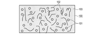
- the synthetic grindstone 100 has an abrasive 101 having a chemical mechanical grinding action on the wafer S, and the friction accelerator 102 is dispersed in the abrasive 101 and bonded by the binder 103. It is formed by forming pores.
- the abrasive 101 is appropriately selected depending on the material of the work material, and when the wafer S is made of a silicon material, it is preferable that the cerium oxide having an average particle size of 10 ⁇ m or less is used as a main component. In addition to cerium oxide, silicon oxide, iron oxide, titanium oxide, and chromium oxide can also be applied, and a mixture thereof may be used.
- the friction accelerator 102 is mainly composed of a fibrous substance having a Mohs hardness lower than that of the wafer S and a high coefficient of friction.
- the fibrous material any or a mixture of whiskers (crystals that grow like whiskers from the crystal surface to the outside), fibers can be applied.
- the whiskers oxide whiskers and carbide whiskers having high mechanical strength are preferable.
- the fiber cellulose fiber and carbon fiber are preferable.
- the binder 103 is mainly composed of an organic compound resin such as a phenol resin, a urethane resin, or an epoxy resin, or a low melting point vitreous binder.
- the composition of the synthetic grindstone 100 is, for example, 40 to 55% by volume of the abrasive 101, 1 to 5% by volume of the friction accelerator 102, and 9 to 30% by volume of the binder 103.
- the porosity of the synthetic grindstone 100 is 10 to 50% by volume. The pores are filled with the friction accelerator 102.
- the synthetic grindstone 100 configured in this way is attached to the CMG device 10 and grinds the wafer S as follows. That is, the synthetic grindstone 100 is attached to the wheel holding member 43. Next, the wafer S is attached to the table 23 by the transfer robot.
- the table motor 21 is driven to rotate the table 23 in the direction of the arrow in FIG.
- the rotary motor unit 41 is driven to rotate the wheel holding member 43 and the synthetic grindstone 100 in the direction of the arrow in FIG.
- the peripheral speed of the synthetic grindstone 100 is rotated at, for example, 600 m / min, and the synthetic grindstone 100 is pressed toward the wafer S side at a processing pressure of 300 g / cm 2 .
- the swing shaft 32 is swung in the direction of the arrow in FIG. By interlocking these, the synthetic grindstone 100 and the wafer S slide.
- FIG. 4 shows the relationship between the synthetic grindstone 100 and the wafer S at this time.
- the synthetic grindstone 100 and the wafer S slide, and an external force acts on the binder 103.
- this external force acts continuously, the binder 103 loosens, and the abrasive 101 and the soft friction accelerator 102 fall off on the wafer S.
- the released abrasive 101 is entangled with the fibrous friction accelerator 102 and slides in the gap between the synthetic grindstone 100 and the wafer S.
- the abrasive 101 has a chemical polishing action, and staying on the surface of the wafer S for a long time leads to an increase in the frequency of opportunities for the chemical polishing action.
- the friction accelerator 102 repeatedly microscopically adheres and peels off by rubbing against the surface of the wafer S and the abrasive 101. Friction heat is generated when this operation acts as a brake. Since the frictional heat is also generated between the abrasive 101 and the binder 103 and the wafer S, it is added to the frictional heat.
- FIG. 4H shows how the frictional heat generated in the gap between the synthetic grindstone 100 and the wafer S spreads from the surface of the wafer S to the inside of the wafer S.
- the friction accelerator 102 is used to promote the chemical reaction due to the temperature rise on the surface of the wafer S, and the grinding efficiency is increased, so that the processing time for surface grinding of the wafer S by the CMG apparatus 10 and the synthetic grindstone 100 is shortened. Can be made to.
- the grinding efficiency can be increased and the processing time can be shortened by combining the temperature raising effect of the friction accelerator 102 and the retention effect of the polishing agent 101.
- FIGS. 1 to 4 are diagrams showing a second embodiment of the present invention.
- the same functional parts as those in FIGS. 1 to 4 are designated by the same reference numerals, and detailed description thereof will be omitted.
- the synthetic grindstone 100A according to the second embodiment of the present invention is attached to the CMG device 10 in the same manner as the synthetic grindstone 100 described above.
- a thickener 104 is added to the synthetic whetstone 100.
- the main component of the thickener 104 is, for example, glycerin.
- glycol may be used, or a mixture thereof may be used.
- a method of adding the thickener 104 it may be directly mixed, or as shown in FIG. 5, it may be impregnated with a solution of glycerin or the like dissolved in a low melting point wax.
- the synthetic grindstone 100A configured in this way is attached to the CMG device 10 and grinds the wafer S in the same manner as the synthetic grindstone 100 described above.
- FIG. 6 shows the relationship between the synthetic grindstone 100A and the wafer S at this time.
- the synthetic grindstone 100A and the wafer S slide, and an external force acts on the binder 103.
- this external force acts continuously, the binder 103 loosens, and the abrasive 101 and the soft friction accelerator 102 fall off on the wafer S.
- the released abrasive 101 is entangled with the fibrous friction accelerator 102 and slides in the gap between the synthetic grindstone 100A and the wafer S.
- the abrasive 101 has a chemical polishing action, and staying on the surface of the wafer S for a long time leads to an increase in the frequency of opportunities for the chemical polishing action.
- the component of the thickener 104 that is, glycerin, which is impregnated inside the synthetic grindstone 100A together with the low melting point wax, begins to elute. Since the low melting point wax has a small molecular weight, the lubricating action between the synthetic grindstone 100A and the wafer S is limited. The thickener 104 eluted in the same manner as the low melting point wax becomes a highly viscous liquid M between the synthetic grindstone 100A and the wafer S.
- FIG. 6H shows how the frictional heat generated in the gap between the synthetic grindstone 100A and the wafer S spreads from the surface of the wafer S to the inside of the wafer S.
- the abrasive 101 Since the abrasive 101 is trapped in the highly viscous liquid N, the effect of suppressing the discharge action of the abrasive 101 and increasing the residence time of the abrasive 101 increases the frequency of opportunities for the chemical polishing action. There is also.
- the grinding efficiency is increased and the processing time is shortened by combining the temperature raising effect of the friction accelerator 102 and the thickener 104 and the retention effect of the abrasive 101. Can be done.
- FIGS. 7 to 8 are diagrams showing a third embodiment of the present invention.
- the same functional parts as those in FIGS. 1 to 6 are designated by the same reference numerals, and detailed description thereof will be omitted.
- the synthetic grindstone 200 according to the second embodiment of the present invention is attached to the CMG device 10 in the same manner as the synthetic grindstone 100 described above.
- the synthetic grindstone 200 is formed by an abrasive 201 having a chemical mechanical grinding action on the wafer S and a binder 202 that disperses and binds the abrasive 201. Further, the binder 202 is impregnated with the thickener 203 having a thickening action dissolved in the low melting point wax as shown in FIG.
- the abrasive 201 is appropriately selected depending on the material of the work material, and when the wafer S is made of a silicon material, it is preferable that the polishing agent 201 contains cerium oxide having an average particle size of 10 ⁇ m or less as a main component. In addition to cerium oxide, silicon oxide and iron oxide can also be applied, and a mixture thereof may be used.
- the binder 202 is mainly composed of an organic substance such as a phenol resin or a low melting point vitreous binder.
- the main component of the thickener 203 is, for example, glycerin.
- glycol may be used, or a mixture thereof may be used.
- a method of adding the thickener 203 it may be directly mixed, or as shown in FIG. 7, it may be impregnated with a solution of glycerin or the like dissolved in a low melting point wax.
- the synthetic grindstone 200 configured in this way is attached to the CMG device 10 and grinds the wafer S as follows. That is, the synthetic grindstone 200 is attached to the wheel holding member 43. Next, the wafer S is attached to the table 23 by the transfer robot.
- the table motor 21 is driven to rotate the table 23 in the direction of the arrow in FIG.
- the rotary motor unit 41 is driven to rotate the wheel holding member 43 and the synthetic grindstone 100 in the direction of the arrow in FIG.
- the peripheral speed of the synthetic grindstone 200 is rotated at, for example, 600 m / min, and the synthetic grindstone 200 is pressed toward the wafer S side at a processing pressure of 300 g / cm 2 .
- the swing shaft 32 is swung in the direction of the arrow in FIG. By interlocking these, the synthetic grindstone 200 and the wafer S slide.
- FIG. 8 shows the relationship between the synthetic grindstone 200 and the wafer S at this time.
- the synthetic grindstone 200 and the wafer S slide, and an external force acts on the binder 202.
- this external force acts continuously, the binder 202 loosens and the abrasive 201 falls off on the wafer S.
- the polishing agent 201 has a chemical polishing action, and grinding of the surface of the wafer S is started.
- the component of the thickener 203 that is, glycerin, which is impregnated inside the synthetic grindstone 200 together with the low melting point wax, begins to elute. Since the low melting point wax has a small molecular weight, the lubricating action between the synthetic grindstone 200 and the wafer S is limited. The thickener 203 eluted in the same manner as the low melting point wax becomes a highly viscous liquid N between the synthetic grindstone 200 and the wafer S.
- FIG. 8H shows how the frictional heat generated in the gap between the synthetic grindstone 200 and the wafer S spreads from the surface of the wafer S to the inside of the wafer S.
- the abrasive 201 Since the abrasive 201 is trapped in the highly viscous liquid N, the effect of suppressing the discharge action of the abrasive 201 and increasing the residence time of the abrasive 201 increases the frequency of opportunities for the chemical polishing action. There is also.
- the thickener 203 can be used to promote the temperature rise on the surface of the wafer S, and the abrasive 201 can be stopped on the working surface. Therefore, by increasing the grinding efficiency, it is possible to shorten the processing time for surface grinding of the wafer S by the CMG device 10 and the synthetic grindstone 200.
- the grinding efficiency can be increased and the processing time can be shortened by combining the temperature raising effect of the thickener 203 and the retention effect of the polishing agent 201.
- the present invention is not limited to the above embodiment, and can be variously modified at the implementation stage without departing from the gist thereof.
- each embodiment may be carried out in combination as appropriate, in which case the combined effect can be obtained.
- the above-described embodiment includes various inventions, and various inventions can be extracted by a combination selected from a plurality of disclosed constituent requirements. For example, even if some constituent requirements are deleted from all the constituent requirements shown in the embodiment, if the problem can be solved and the effect is obtained, the configuration in which the constituent requirements are deleted can be extracted as an invention.
Landscapes
- Engineering & Computer Science (AREA)
- Mechanical Engineering (AREA)
- Chemical & Material Sciences (AREA)
- Inorganic Chemistry (AREA)
- Ceramic Engineering (AREA)
- Materials Engineering (AREA)
- Organic Chemistry (AREA)
- Polishing Bodies And Polishing Tools (AREA)
- Mechanical Treatment Of Semiconductor (AREA)
Abstract
ウェーハSを化学機械研削する合成砥石(100)において、平均粒径が10μm以下の酸化セリウムを主成分とし、ウェーハSに対し化学機械研削作用を有する研磨剤(101)と、ウェーハSよりも低いモース硬度で、かつ、高い摩擦係数を有する繊維物質を主成分とし、発熱作用を有する摩擦促進剤(102)と、フェノール樹脂を主成分とし、研磨剤(101)と摩擦促進剤(102)を分散して結合する結合剤(103)とを備えている。
Description
本発明は、シリコンウェーハ等の被削物の表面をグライディング加工するための合成砥石に関する。
半導体製造分野では、半導体素子の基板となるシリコンウェーハの表面の加工はシリコン単結晶インゴッドをスライスしたウェーハをラッピング工程、エッチング工程、ポリッシング工程等の数段の工程を経て鏡面に仕上げるのが一般的である。ラッピング工程においては、平行度、平坦度等の寸法精度、形状精度を得る。次いで、エッチング工程においてはラッピング工程でできた加工変質層を除去する。更にポリッシング工程においては、ケミカルメカニカル研磨(以下、「CMP」と称する。)により、良好な形状精度を維持した上で鏡面レベルの面粗さを持ったウェーハを形成する。また、これと同等のポリシング工程は半導体後工程においてバックグラインドと呼ばれる研削加工のダメージを除去する際にも用いられる。
近年、ポリッシング工程の代わりに、乾式のケミカルメカニカル研削(以下、「CMG」と称する。)による表面加工を行う方法が用いられている(例えば、特許文献1参照)。CMG工程では、研磨剤(砥粒)を硬質樹脂等の樹脂結合剤で固定化した合成砥石を用いる。そして、ウェーハ及び合成砥石を回転させながら合成砥石をウェーハに押圧させる(例えば、特許文献2参照)。ウェーハ表面の凸部は、合成砥石との摩擦により微細な加工起点が加熱・酸化されて脆くなって剥がれ落ちる。このようにして、ウェーハの凸部だけが研削され、平坦化される。
また、CMG工程において、研削レートを向上させることで、加工能率を向上させる合成砥石が提案されている(例えば、特許文献3参照)。
上述した合成砥石は、次のような問題があった。すなわち、上述したようにCMG工程では、固体間の化学反応を利用して材料除去を加工原理としているため、反応熱が十分に上昇しないと加工速度が上昇しなかった。また、合成砥石から遊離した研磨剤が合成砥石又はウェーハの回転に伴う遠心力で排出され、研削作用に関与せず、加工速度が低下するという問題もあった。
そこで、本発明は上記の課題を解決するためになされたものであり、研削加工における高い研削効率を実現する合成砥石を提供することを目的とする。
本実施形態に係る合成砥石は、被削材に対し化学機械研削作用を有する研磨剤と、摩擦促進剤と、前記研磨剤と前記摩擦促進剤を結合する結合剤とを備えている。
本実施形態に係る合成砥石は、被削材に対し化学機械研削作用を有する研磨剤と、前記研磨剤を結合する結合剤を具備し、前記結合剤には、増粘作用を有する増粘剤が含浸されている、又は、前記増粘剤が低融点ワックスで溶解されて含浸されている。
研削加工における摩擦による発熱を促進し、短時間で温度上昇を図ることで、高い研削効率を実現することが可能となる。
図1~図4は、本発明の第1の実施の形態を示す図である。なお、これらの図においてSは研削対象となるシリコンウェーハ(被削物)を示している。図1に示すように、CMG装置10は、ウェーハSを支持する回転テーブル機構20と、後述する合成砥石100を支持する砥石支持機構30とを備えている。CMG装置10は、ウェーハ処理装置の一部を構成している。CMG装置10には、搬送ロボット等によりウェーハSが搬入・搬出される。
回転テーブル機構20は、床面に配置されるテーブルモータ21と、このテーブルモータ21から上方に突出して配置されたテーブル軸22と、このテーブル軸22の上端に取り付けられたテーブル23を備えている。テーブル23は、研削対象であるウェーハSを着脱自在に保持する機構を有している。保持する機構としては、例えば真空吸着機構がある。
砥石支持機構30は、床面に配置されると共に内部にモータが収容された架台31と、この架台31に支持され、架台31内のモータによって図1中矢印方向に揺動する鉛直方向の揺動軸32と、この揺動軸32の上端に設けられ、水平方向に延設されるアーム33と、このアーム33の先端側に設けられた砥石駆動機構40を備えている。
砥石駆動機構40は、回転モータ部41を備えている。回転モータ部41は、下方に突出した回転軸42を備えている。回転軸42の先端部には円板状のホイール保持部材43が取り付けられている。ホイール保持部材43には、図2に示すように、円板状の合成砥石100が着脱自在に取り付けられている。合成砥石100の装着には、合成砥石100に設けられたネジ孔に、ホイール保持部材43側からボルトをネジ込んで装着する。
合成砥石100は、図3に示すように、ウェーハSに対し化学機械研削作用を有する研磨剤101を有し、この研磨剤101内に摩擦促進剤102を分散して結合剤103によって結合し、気孔を形成して形成されている。研磨剤101は、被削材の材質によって適宜選択されるものであり、ウェーハSがシリコン材製の場合には、平均粒径が10μm以下の酸化セリウムを主成分とすることが好ましい。なお、酸化セリウムの他、酸化ケイ素、酸化鉄、酸化チタン、酸化クロムも適用でき、これらの混合物でも良い。
摩擦促進剤102は、ウェーハSよりも低いモース硬度で、かつ、高い摩擦係数を有する繊維物質を主成分とする。繊維物質は、ウィスカ(結晶表面から外側に向けて髭状に成長した結晶)、ファイバのいずれか又は混合物を適用できる。ウィスカとしては、機械的強度の大きな酸化物系ウィスカ及び炭化物系ウィスカが好ましい。ファイバとしては、セルロースファイバ及びカーボンファイバが好ましい。結合剤103は、フェノール樹脂、ウレタン樹脂、エポキシ樹脂等の有機化合物系樹脂又は低融点ガラス質結合剤を主成分としている。
なお、合成砥石100の組成は例えば、研磨剤101が40~55体積%、摩擦促進剤102が1~5体積%、結合剤103が9~30体積%である。また、合成砥石100の気孔率は10~50体積%である。気孔には、摩擦促進剤102が充填される。
このように構成された合成砥石100は、CMG装置10に取り付けられて、次のようにしてウェーハSを研削する。すなわち、合成砥石100をホイール保持部材43に取り付ける。次に、搬送ロボットによりウェーハSをテーブル23に取り付ける。
次に、テーブルモータ21を駆動して、テーブル23を図1中矢印方向に回転させる。また、回転モータ部41を駆動して、ホイール保持部材43及び合成砥石100を図1中矢印方向に回転させる。合成砥石100の周速を例えば、600m/minで回転させると共に、加工圧力300g/cm2でウェーハS側に押圧する。さらに、揺動軸32を図1中矢印方向に揺動させる。これらが連動することで、合成砥石100とウェーハSとが摺動する。
この時の合成砥石100とウェーハSとの関係を図4に示す。加工が開始されると、合成砥石100とウェーハSが摺動し、結合剤103に外力が作用する。この外力が連続して作用することで結合剤103が緩み、研磨剤101及び軟質の摩擦促進剤102がウェーハS上に脱落する。遊離した研磨剤101は、繊維状の摩擦促進剤102に絡まり、合成砥石100とウェーハSとの隙間において摺動される。研磨剤101は化学研磨作用を有しており、ウェーハS表面に長く滞留することで化学研磨作用の機会頻度の向上につながる。
一方、摩擦促進剤102は、ウェーハS表面及び研磨剤101と擦れあうことで微視的な凝着と剥離を繰り返す。この動作がブレーキ作用となることで摩擦熱が発生する。摩擦熱は、研磨剤101及び結合剤103とウェーハSとの間でも生じているため、その摩擦熱に加わることとなる。図4中Hは、合成砥石100とウェーハSとの隙間で生じた摩擦熱がウェーハS表面からウェーハS内部に拡がる様子を示している。
CMG工程による加工量Lは、Prestonの公式から導かれる。すなわち、L=k・P・V・t(k:Preston係数、P:砥石面圧力、V:砥石相対速度、t:加工時間)により表される。研磨効率(V/t)を促進させる比例定数kの要因の一つとして熱影響がある。
熱化学反応式は一般にアレニウスの式によりk(速度定数)=Aexp(-E/RT)と示され(A:反応係数、E:活性化エネルギ、R:気体定数、T:絶対温度)、絶対温度Tに対し正の相関となる。したがって、発熱量を大きくすることで加工雰囲気において熱が発生すると化学作用の駆動エネルギとなり、化学反応は促進され、加工量は増加する。
一方、摩擦係数μと発生熱量Qは一般的な公式ΔQ=μ・ΔW・v/J(ΔW:加えた仕事量、v:すべり速度、J:仕事量を熱量に変換する換算定数)で示されることから、摩擦係数の増大で絶対温度TはQの積分値として示される。よって摩擦係数、特に、動摩擦係数が大きいほど温度上昇も大きくなる。
このようにして摩擦促進剤102を用いてウェーハS表面の温度上昇による化学反応を促進し、研削効率が上昇させることで、CMG装置10及び合成砥石100によるウェーハSの表面研削の加工時間を短縮させることができる。
本実施の形態に係る合成砥石100によれば、摩擦促進剤102による温度上昇効果及び研磨剤101の滞留効果を組み合わせることで、研削効率が上昇し、加工時間を短縮させることができる。
図5~図6は、本発明の第2の実施の形態を示す図である。これらの図において、図1~図4と同一機能部分には同一符号を付し、その詳細な説明は省略する。本発明の第2の実施の形態に係る合成砥石100Aは、上述した合成砥石100と同様に、CMG装置10に取り付けられる。
合成砥石100Aは、合成砥石100に対し、増粘剤104が加えられている。増粘剤104の主成分は、例えばグリセリンである。なお、グリセリンの他、グリコールでも良く、これらの混合物でも良い。また、増粘剤104の添加方法としては、直接混合しても良いし、図5に示すように、グリセリン等を低融点ワックスで溶解させたものを含浸させるようにしても良い。
このように構成された合成砥石100Aは、CMG装置10に取り付けられて、上述した合成砥石100と同様にウェーハSを研削する。
この時の合成砥石100AとウェーハSとの関係を図6に示す。加工が開始されると、合成砥石100AとウェーハSが摺動し、結合剤103に外力が作用する。この外力が連続して作用することで結合剤103が緩み、研磨剤101及び軟質の摩擦促進剤102がウェーハS上に脱落する。遊離した研磨剤101は、繊維状の摩擦促進剤102に絡まり、合成砥石100AとウェーハSとの隙間において摺動される。研磨剤101は化学研磨作用を有しており、ウェーハS表面に長く滞留することで化学研磨作用の機会頻度の向上につながる。
さらに、合成砥石100AとウェーハSとの間の摺動及び摩擦促進剤102の摺動により、摩擦熱が発生する。これにより、合成砥石100A内部に低融点ワックスと共に含浸した増粘剤104の成分、すなわちグリセリンが溶出を初める。低融点ワックスは分子量が少ないために合成砥石100AとウェーハS間の潤滑作用は限定的である。その低融点ワックスと同じくして溶出した増粘剤104は合成砥石100AとウェーハS間で高粘度な液体Mとなる。
その結果、合成砥石100AとウェーハSとの極く狭い隙間の中で高い剪断応力をもつ液体となり、結果的に摩擦熱を生じる。生じた摩擦熱は液体M内に留まり易く、温度上昇による化学反応を促進し、研削効率が上昇する。したがって、CMG装置10及び合成砥石100AによるウェーハSの表面研削の加工時間を短縮させることができる。図6中Hは、合成砥石100AとウェーハSとの隙間で生じた摩擦熱がウェーハS表面からウェーハS内部に拡がる様子を示している。なお、高粘度の液体N内によって研磨剤101がトラップされるため、研磨剤101の排出作用が抑制され、研磨剤101の滞留時間が長くなることで化学研磨作用の機会頻度が向上するという効果もある。
本実施の形態に係る合成砥石100Aによれば、摩擦促進剤102及び増粘剤104による温度上昇効果及び研磨剤101の滞留効果を組み合わせることで、研削効率が上昇し、加工時間を短縮させることができる。
図7~図8は、本発明の第3の実施の形態を示す図である。これらの図において、図1~図6と同一機能部分には同一符号を付し、その詳細な説明は省略する。本発明の第2の実施の形態に係る合成砥石200は、上述した合成砥石100と同様に、CMG装置10に取り付けられる。
合成砥石200は、ウェーハSに対し化学機械研削作用を有する研磨剤201と、この研磨剤201を分散して結合する結合剤202とによって形成されている。また、結合剤202には、増粘作用を有する増粘剤203が低融点ワックスに溶解され、図7に示すようにして含浸されている。
研磨剤201は、被削材の材質によって適宜選択されるものであり、ウェーハSがシリコン材製の場合には、平均粒径が10μm以下の酸化セリウムを主成分とすることが好ましい。なお、酸化セリウムの他、酸化ケイ素、酸化鉄も適用でき、これらの混合物でも良い。
結合剤202は、フェノール樹脂等の有機物又は低融点ガラス質結合剤を主成分としている。増粘剤203の主成分は、例えばグリセリンである。なお、グリセリンの他、グリコールでも良く、これらの混合物でも良い。また、増粘剤203の添加方法としては、直接混合しても良いし、図7に示すように、グリセリン等を低融点ワックスで溶解させたものを含浸させるようにしても良い。
このように構成された合成砥石200は、CMG装置10に取り付けられて、次のようにしてウェーハSを研削する。すなわち、合成砥石200をホイール保持部材43に取り付ける。次に、搬送ロボットによりウェーハSをテーブル23に取り付ける。
次に、テーブルモータ21を駆動して、テーブル23を図1中矢印方向に回転させる。また、回転モータ部41を駆動して、ホイール保持部材43及び合成砥石100を図1中矢印方向に回転させる。合成砥石200の周速を例えば、600m/minで回転させると共に、加工圧力300g/cm2でウェーハS側に押圧する。さらに、揺動軸32を図1中矢印方向に揺動させる。これらが連動することで、合成砥石200とウェーハSとが摺動する。
この時の合成砥石200とウェーハSとの関係を図8に示す。加工が開始されると、合成砥石200とウェーハSが摺動し、結合剤202に外力が作用する。この外力が連続して作用することで結合剤202が緩み、研磨剤201がウェーハS上に脱落する。研磨剤201は化学研磨作用を有しており、ウェーハS表面の研削が開始される。
一方、合成砥石200とウェーハSとの間の摺動により、摩擦熱が発生する。これにより、合成砥石200内部に低融点ワックスと共に含浸した増粘剤203の成分、すなわちグリセリンが溶出を初める。低融点ワックスは分子量が少ないために合成砥石200とウェーハS間の潤滑作用は限定的である。その低融点ワックスと同じくして溶出した増粘剤203は合成砥石200とウェーハS間で高粘度な液体Nとなる。
その結果、合成砥石200とウェーハSとの極く薄い隙間の中で高い剪断応力をもつ液体となり、結果的に摩擦熱を生じる。生じた摩擦熱は液体N内に留まり易く、温度上昇による化学反応を促進し、研削効率が上昇する。したがって、CMG装置10及び合成砥石200によるウェーハSの表面研削の加工時間を短縮させることができる。図8中Hは、合成砥石200とウェーハSとの隙間で生じた摩擦熱がウェーハS表面からウェーハS内部に拡がる様子を示している。なお、高粘度の液体N内によって研磨剤201がトラップされるため、研磨剤201の排出作用が抑制され、研磨剤201の滞留時間が長くなることで化学研磨作用の機会頻度が向上するという効果もある。
このようにして増粘剤203を用いてウェーハS表面の温度上昇を促進すると共に、研磨剤201を作用面に止めることができる。したがって、研削効率を上昇させることで、CMG装置10及び合成砥石200によるウェーハSの表面研削の加工時間を短縮させることができる。
本実施の形態に係る合成砥石200によれば、増粘剤203による温度上昇効果及び研磨剤201の滞留効果を組み合わせることで、研削効率が上昇し、加工時間を短縮させることができる。
なお、本発明は、上記実施形態に限定されるものではなく、実施段階ではその要旨を逸脱しない範囲で種々に変形することが可能である。また、各実施形態は適宜組み合わせて実施してもよく、その場合組み合わせた効果が得られる。更に、上記実施形態には種々の発明が含まれており、開示される複数の構成要件から選択された組み合わせにより種々の発明が抽出され得る。例えば、実施形態に示される全構成要件からいくつかの構成要件が削除されても、課題が解決でき、効果が得られる場合には、この構成要件が削除された構成が発明として抽出され得る。
10…CMG装置、20…回転テーブル機構、21…テーブルモータ、22…テーブル軸、23…テーブル、30…砥石支持機構、31…架台、32…揺動軸、33…アーム、40…砥石駆動機構、41…回転モータ部、42…回転軸、43…ホイール保持部材、100,100A…合成砥石、101…研磨剤、102…摩擦促進剤、103…結合剤、104…増粘剤、200…合成砥石、201…研磨剤、202…結合剤、203…増粘剤、S…ウェーハ。
Claims (9)
- 被削材を化学機械研削する合成砥石において、
前記被削材に対し化学機械研削作用を有する研磨剤と、
摩擦促進剤と、
前記研磨剤と前記摩擦促進剤を結合する結合剤とを備えている合成砥石。 - 前記研磨剤は、酸化セリウム、酸化ケイ素、酸化鉄、酸化チタン、酸化クロムのいずれか又は混合物を主成分とし、平均粒径が10μm以下である請求項1に記載の合成砥石。
- 前記摩擦促進剤は、前記被削材よりも低いモース硬度で、かつ、高い摩擦係数を有する繊維物質を主成分とする請求項1に記載の合成砥石。
- 前記摩擦促進剤は、ウィスカ、ファイバのいずれか又は混合物を主成分とする請求項3に記載の合成砥石。
- 前記結合剤は、有機化合物系樹脂又は低融点ガラス質結合剤を主成分とする請求項1に記載の合成砥石。
- 前記結合剤には、増粘作用を有する増粘剤が含浸されている、又は、前記増粘剤が低融点ワックスで溶解されて含浸されている請求項1に記載の合成砥石。
- 前記増粘剤は、グリセリン又はグリコールの少なくとも一方を主成分とする請求項6に記載の合成砥石。
- 被削材を化学機械研削する合成砥石において、
前記被削材に対し化学機械研削作用を有する研磨剤と、
前記研磨剤を結合する結合剤を具備し、
前記結合剤には、増粘作用を有する増粘剤が含浸されている、又は、前記増粘剤が低融点ワックスで溶解されて含浸されている合成砥石。 - 前記増粘剤は、グリセリン又はグリコールの少なくとも一方を主成分とする請求項8に記載の合成砥石。
Priority Applications (4)
| Application Number | Priority Date | Filing Date | Title |
|---|---|---|---|
| EP20834645.2A EP3995255A4 (en) | 2019-07-02 | 2020-06-19 | SYNTHETIC GRINDING STONE |
| CN202080047180.2A CN114025916A (zh) | 2019-07-02 | 2020-06-19 | 合成磨石 |
| KR1020217040206A KR20220006106A (ko) | 2019-07-02 | 2020-06-19 | 합성 지석 |
| US17/538,153 US20220088746A1 (en) | 2019-07-02 | 2021-11-30 | Synthetic grindstone |
Applications Claiming Priority (2)
| Application Number | Priority Date | Filing Date | Title |
|---|---|---|---|
| JP2019-123773 | 2019-07-02 | ||
| JP2019123773A JP6779541B1 (ja) | 2019-07-02 | 2019-07-02 | 合成砥石 |
Related Child Applications (1)
| Application Number | Title | Priority Date | Filing Date |
|---|---|---|---|
| US17/538,153 Continuation US20220088746A1 (en) | 2019-07-02 | 2021-11-30 | Synthetic grindstone |
Publications (1)
| Publication Number | Publication Date |
|---|---|
| WO2021002216A1 true WO2021002216A1 (ja) | 2021-01-07 |
Family
ID=73022359
Family Applications (1)
| Application Number | Title | Priority Date | Filing Date |
|---|---|---|---|
| PCT/JP2020/024053 Ceased WO2021002216A1 (ja) | 2019-07-02 | 2020-06-19 | 合成砥石 |
Country Status (7)
| Country | Link |
|---|---|
| US (1) | US20220088746A1 (ja) |
| EP (1) | EP3995255A4 (ja) |
| JP (1) | JP6779541B1 (ja) |
| KR (1) | KR20220006106A (ja) |
| CN (1) | CN114025916A (ja) |
| TW (1) | TWI772824B (ja) |
| WO (1) | WO2021002216A1 (ja) |
Cited By (2)
| Publication number | Priority date | Publication date | Assignee | Title |
|---|---|---|---|---|
| TWI846117B (zh) * | 2021-11-17 | 2024-06-21 | 日商斯庫林集團股份有限公司 | 基板處理裝置 |
| US12304024B2 (en) | 2021-06-14 | 2025-05-20 | Disco Corporation | Polishing tool |
Families Citing this family (4)
| Publication number | Priority date | Publication date | Assignee | Title |
|---|---|---|---|---|
| JP7262864B1 (ja) | 2022-09-28 | 2023-04-24 | 株式会社東京ダイヤモンド工具製作所 | 合成砥石、合成砥石アセンブリ、及び、合成砥石の製造方法 |
| JP7751863B1 (ja) * | 2025-03-19 | 2025-10-09 | 有限会社サクセス | 半導体結晶の研削加工方法および当該研削加工方法において使用される研削加工用の砥石 |
| JP7659285B1 (ja) | 2024-06-26 | 2025-04-09 | 有限会社サクセス | 半導体結晶の研削加工方法および当該研削加工方法において使用される研削加工用の砥石 |
| WO2026004548A1 (ja) * | 2024-06-26 | 2026-01-02 | 有限会社サクセス | 半導体結晶の研削加工方法および当該研削加工方法において使用される研削加工用の砥石 |
Citations (10)
| Publication number | Priority date | Publication date | Assignee | Title |
|---|---|---|---|---|
| JPS50140982A (ja) * | 1974-04-26 | 1975-11-12 | ||
| JPH0386465A (ja) * | 1989-08-25 | 1991-04-11 | Mizuho Kenma Toishi Kk | 超硬砥粒超仕上げ砥石 |
| JPH07241775A (ja) * | 1994-03-03 | 1995-09-19 | Kanebo Ltd | 合成砥石及びバフ材並びにその製造方法 |
| JP2002086361A (ja) * | 2000-09-14 | 2002-03-26 | Xebec Technology Co Ltd | 弾性砥石 |
| JP2004087912A (ja) | 2002-08-28 | 2004-03-18 | Okamoto Machine Tool Works Ltd | 基板の乾式化学機械研磨方法およびそれに用いる装置 |
| JP2008229761A (ja) * | 2007-03-19 | 2008-10-02 | Disco Abrasive Syst Ltd | 乾式研磨砥石 |
| JP4573492B2 (ja) | 2001-03-27 | 2010-11-04 | 株式会社東京ダイヤモンド工具製作所 | 合成砥石 |
| JP2016082127A (ja) | 2014-10-20 | 2016-05-16 | 三井研削砥石株式会社 | 研磨工具 |
| JP2016514627A (ja) * | 2013-03-29 | 2016-05-23 | スリーエム イノベイティブ プロパティズ カンパニー | 不織布研磨物品及びその製造方法 |
| JP2018521866A (ja) * | 2015-06-29 | 2018-08-09 | サンーゴバン アブレイシブズ,インコーポレイティド | 砥粒品および形成方法 |
Family Cites Families (18)
| Publication number | Priority date | Publication date | Assignee | Title |
|---|---|---|---|---|
| JPS59169764A (ja) * | 1983-03-14 | 1984-09-25 | Kanebo Ltd | 固型砥石 |
| JPH09207071A (ja) * | 1995-12-01 | 1997-08-12 | Masayuki Oka | 油脂研摩剤入り海綿状樹脂砥石 |
| JPH09314471A (ja) * | 1996-05-28 | 1997-12-09 | Mitsubishi Materials Corp | ブレードおよびその製造方法 |
| US5919549A (en) * | 1996-11-27 | 1999-07-06 | Minnesota Mining And Manufacturing Company | Abrasive articles and method for the manufacture of same |
| US6719615B1 (en) * | 2000-10-10 | 2004-04-13 | Beaver Creek Concepts Inc | Versatile wafer refining |
| JP2000301459A (ja) * | 1999-04-19 | 2000-10-31 | Nippei Toyama Corp | 砥石およびこれを用いた研磨方法 |
| JP2000301461A (ja) * | 1999-04-21 | 2000-10-31 | Nippei Toyama Corp | 砥石の製造方法および研磨方法 |
| US6755720B1 (en) * | 1999-07-15 | 2004-06-29 | Noritake Co., Limited | Vitrified bond tool and method of manufacturing the same |
| US20020016139A1 (en) * | 2000-07-25 | 2002-02-07 | Kazuto Hirokawa | Polishing tool and manufacturing method therefor |
| JP2004106080A (ja) * | 2002-09-17 | 2004-04-08 | Okamoto Machine Tool Works Ltd | 基板の乾式化学機械研磨方法および乾式化学機械研磨装置 |
| JP4357173B2 (ja) * | 2002-12-27 | 2009-11-04 | 善二郎 小柳津 | ポリ尿素弾性研削材及びその製造方法 |
| JP2004235201A (ja) * | 2003-01-28 | 2004-08-19 | Okamoto Machine Tool Works Ltd | 基板の乾式化学機械研磨方法および乾式化学機械研磨装置 |
| JP2008006559A (ja) * | 2006-06-30 | 2008-01-17 | Hitachi Maxell Ltd | 鏡面加工方法、および鏡面加工用の加工体 |
| DE102009038941B4 (de) * | 2009-08-26 | 2013-03-21 | Siltronic Ag | Verfahren zur Herstellung einer Halbleiterscheibe |
| CN101780662A (zh) * | 2010-03-17 | 2010-07-21 | 大连理工大学 | 超精密低损伤磨削硅片的软磨料砂轮 |
| JP2013240867A (ja) * | 2012-05-22 | 2013-12-05 | Mezoteku Dia Kk | 表面研磨板 |
| JP6734018B2 (ja) * | 2014-09-17 | 2020-08-05 | 株式会社フジミインコーポレーテッド | 研磨材、研磨用組成物、及び研磨方法 |
| MX365727B (es) * | 2015-04-14 | 2019-06-12 | 3M Innovative Properties Co | Articulo abrasivo de tela no tejida y metodo para fabricarlo. |
-
2019
- 2019-07-02 JP JP2019123773A patent/JP6779541B1/ja active Active
-
2020
- 2020-06-19 KR KR1020217040206A patent/KR20220006106A/ko active Pending
- 2020-06-19 WO PCT/JP2020/024053 patent/WO2021002216A1/ja not_active Ceased
- 2020-06-19 TW TW109120909A patent/TWI772824B/zh active
- 2020-06-19 CN CN202080047180.2A patent/CN114025916A/zh active Pending
- 2020-06-19 EP EP20834645.2A patent/EP3995255A4/en not_active Withdrawn
-
2021
- 2021-11-30 US US17/538,153 patent/US20220088746A1/en not_active Abandoned
Patent Citations (10)
| Publication number | Priority date | Publication date | Assignee | Title |
|---|---|---|---|---|
| JPS50140982A (ja) * | 1974-04-26 | 1975-11-12 | ||
| JPH0386465A (ja) * | 1989-08-25 | 1991-04-11 | Mizuho Kenma Toishi Kk | 超硬砥粒超仕上げ砥石 |
| JPH07241775A (ja) * | 1994-03-03 | 1995-09-19 | Kanebo Ltd | 合成砥石及びバフ材並びにその製造方法 |
| JP2002086361A (ja) * | 2000-09-14 | 2002-03-26 | Xebec Technology Co Ltd | 弾性砥石 |
| JP4573492B2 (ja) | 2001-03-27 | 2010-11-04 | 株式会社東京ダイヤモンド工具製作所 | 合成砥石 |
| JP2004087912A (ja) | 2002-08-28 | 2004-03-18 | Okamoto Machine Tool Works Ltd | 基板の乾式化学機械研磨方法およびそれに用いる装置 |
| JP2008229761A (ja) * | 2007-03-19 | 2008-10-02 | Disco Abrasive Syst Ltd | 乾式研磨砥石 |
| JP2016514627A (ja) * | 2013-03-29 | 2016-05-23 | スリーエム イノベイティブ プロパティズ カンパニー | 不織布研磨物品及びその製造方法 |
| JP2016082127A (ja) | 2014-10-20 | 2016-05-16 | 三井研削砥石株式会社 | 研磨工具 |
| JP2018521866A (ja) * | 2015-06-29 | 2018-08-09 | サンーゴバン アブレイシブズ,インコーポレイティド | 砥粒品および形成方法 |
Non-Patent Citations (1)
| Title |
|---|
| See also references of EP3995255A4 |
Cited By (2)
| Publication number | Priority date | Publication date | Assignee | Title |
|---|---|---|---|---|
| US12304024B2 (en) | 2021-06-14 | 2025-05-20 | Disco Corporation | Polishing tool |
| TWI846117B (zh) * | 2021-11-17 | 2024-06-21 | 日商斯庫林集團股份有限公司 | 基板處理裝置 |
Also Published As
| Publication number | Publication date |
|---|---|
| CN114025916A (zh) | 2022-02-08 |
| JP2021008016A (ja) | 2021-01-28 |
| TWI772824B (zh) | 2022-08-01 |
| US20220088746A1 (en) | 2022-03-24 |
| TW202106848A (zh) | 2021-02-16 |
| JP6779541B1 (ja) | 2020-11-04 |
| EP3995255A1 (en) | 2022-05-11 |
| EP3995255A4 (en) | 2023-07-12 |
| KR20220006106A (ko) | 2022-01-14 |
Similar Documents
| Publication | Publication Date | Title |
|---|---|---|
| JP6779541B1 (ja) | 合成砥石 | |
| CN101972979B (zh) | 一种金刚石表面化学机械复合研磨抛光方法与装置 | |
| JP6779540B1 (ja) | 合成砥石 | |
| JP5314030B2 (ja) | 硬質かつ/または脆性の材料の研磨加工 | |
| TWI460777B (zh) | 用於研磨半導體晶圓的方法 | |
| JP7106209B2 (ja) | SiC基板の研磨方法 | |
| WO2008117883A1 (ja) | 合成砥石 | |
| JP2021053738A (ja) | 研削装置及び研削ヘッド | |
| CN104981324A (zh) | 单晶SiC基板的表面加工方法、其制造方法和单晶SiC基板的表面加工用磨削板 | |
| CN112139859A (zh) | 一种无水抛光kdp晶体的方法 | |
| CN110039381A (zh) | 圆柱滚子的超精密抛光方法 | |
| CN113182938B (zh) | 金刚石复相材料表面的加工方法 | |
| CN102574266A (zh) | 半导体晶片的研磨方法 | |
| JP4594545B2 (ja) | 研磨装置及びこれを含んだ研削・研磨機 | |
| CN115091354B (zh) | 用于对陶瓷的表面进行研磨的磨具 | |
| JP2012238824A (ja) | 断熱性を有するcmp装置用補助板及び回転定盤 | |
| JP7747505B2 (ja) | ビトリファイドボンド砥石 | |
| JP2006210488A (ja) | メカノケミカル研磨方法及びメカノケミカル研磨装置 | |
| RU2295798C2 (ru) | Способ полирования полупроводниковых материалов | |
| JPH05170B2 (ja) | ||
| JP4580118B2 (ja) | 研磨方法及び研削・研磨方法 | |
| CN111409015B (zh) | 一种磨床机构、研磨工艺及其研磨材料的制备工艺 | |
| US20230142939A1 (en) | MANUFACTURING METHOD OF SiC SUBSTRATE | |
| JP2025134673A (ja) | 絶縁層用研削ホイール | |
| Tanaka | Experimental Trial of Fullerene Wheel Fabrication |
Legal Events
| Date | Code | Title | Description |
|---|---|---|---|
| 121 | Ep: the epo has been informed by wipo that ep was designated in this application |
Ref document number: 20834645 Country of ref document: EP Kind code of ref document: A1 |
|
| ENP | Entry into the national phase |
Ref document number: 20217040206 Country of ref document: KR Kind code of ref document: A |
|
| NENP | Non-entry into the national phase |
Ref country code: DE |
|
| ENP | Entry into the national phase |
Ref document number: 2020834645 Country of ref document: EP Effective date: 20220202 |