WO2021002421A1 - 制御システム - Google Patents
制御システム Download PDFInfo
- Publication number
- WO2021002421A1 WO2021002421A1 PCT/JP2020/025985 JP2020025985W WO2021002421A1 WO 2021002421 A1 WO2021002421 A1 WO 2021002421A1 JP 2020025985 W JP2020025985 W JP 2020025985W WO 2021002421 A1 WO2021002421 A1 WO 2021002421A1
- Authority
- WO
- WIPO (PCT)
- Prior art keywords
- unit
- timer
- counter
- time
- data
- Prior art date
- Legal status (The legal status is an assumption and is not a legal conclusion. Google has not performed a legal analysis and makes no representation as to the accuracy of the status listed.)
- Ceased
Links
Images


Classifications
-
- G—PHYSICS
- G05—CONTROLLING; REGULATING
- G05B—CONTROL OR REGULATING SYSTEMS IN GENERAL; FUNCTIONAL ELEMENTS OF SUCH SYSTEMS; MONITORING OR TESTING ARRANGEMENTS FOR SUCH SYSTEMS OR ELEMENTS
- G05B19/00—Program-control systems
- G05B19/02—Program-control systems electric
- G05B19/04—Program control other than numerical control, i.e. in sequence controllers or logic controllers
- G05B19/05—Programmable logic controllers, e.g. simulating logic interconnections of signals according to ladder diagrams or function charts
- G05B19/054—Input/output
-
- G—PHYSICS
- G05—CONTROLLING; REGULATING
- G05B—CONTROL OR REGULATING SYSTEMS IN GENERAL; FUNCTIONAL ELEMENTS OF SUCH SYSTEMS; MONITORING OR TESTING ARRANGEMENTS FOR SUCH SYSTEMS OR ELEMENTS
- G05B19/00—Program-control systems
- G05B19/02—Program-control systems electric
- G05B19/04—Program control other than numerical control, i.e. in sequence controllers or logic controllers
- G05B19/05—Programmable logic controllers, e.g. simulating logic interconnections of signals according to ladder diagrams or function charts
- G05B19/052—Linking several PLC's
-
- G—PHYSICS
- G05—CONTROLLING; REGULATING
- G05B—CONTROL OR REGULATING SYSTEMS IN GENERAL; FUNCTIONAL ELEMENTS OF SUCH SYSTEMS; MONITORING OR TESTING ARRANGEMENTS FOR SUCH SYSTEMS OR ELEMENTS
- G05B19/00—Program-control systems
- G05B19/02—Program-control systems electric
- G05B19/418—Total factory control, i.e. centrally controlling a plurality of machines, e.g. direct or distributed numerical control [DNC], flexible manufacturing systems [FMS], integrated manufacturing systems [IMS] or computer integrated manufacturing [CIM]
- G05B19/41865—Total factory control, i.e. centrally controlling a plurality of machines, e.g. direct or distributed numerical control [DNC], flexible manufacturing systems [FMS], integrated manufacturing systems [IMS] or computer integrated manufacturing [CIM] characterised by job scheduling, process planning, material flow
-
- G—PHYSICS
- G06—COMPUTING OR CALCULATING; COUNTING
- G06F—ELECTRIC DIGITAL DATA PROCESSING
- G06F1/00—Details not covered by groups G06F3/00 - G06F13/00 and G06F21/00
- G06F1/04—Generating or distributing clock signals or signals derived directly therefrom
- G06F1/12—Synchronisation of different clock signals provided by a plurality of clock generators
-
- G—PHYSICS
- G06—COMPUTING OR CALCULATING; COUNTING
- G06F—ELECTRIC DIGITAL DATA PROCESSING
- G06F1/00—Details not covered by groups G06F3/00 - G06F13/00 and G06F21/00
- G06F1/04—Generating or distributing clock signals or signals derived directly therefrom
- G06F1/14—Time supervision arrangements, e.g. real time clock
-
- G—PHYSICS
- G06—COMPUTING OR CALCULATING; COUNTING
- G06F—ELECTRIC DIGITAL DATA PROCESSING
- G06F15/00—Digital computers in general; Data processing equipment in general
- G06F15/16—Combinations of two or more digital computers each having at least an arithmetic unit, a program unit and a register, e.g. for a simultaneous processing of several programs
- G06F15/163—Interprocessor communication
- G06F15/173—Interprocessor communication using an interconnection network, e.g. matrix, shuffle, pyramid, star, snowflake
- G06F15/17306—Intercommunication techniques
- G06F15/17325—Synchronisation; Hardware support therefor
-
- G—PHYSICS
- G05—CONTROLLING; REGULATING
- G05B—CONTROL OR REGULATING SYSTEMS IN GENERAL; FUNCTIONAL ELEMENTS OF SUCH SYSTEMS; MONITORING OR TESTING ARRANGEMENTS FOR SUCH SYSTEMS OR ELEMENTS
- G05B2219/00—Program-control systems
- G05B2219/10—Plc systems
- G05B2219/13—Plc programming
- G05B2219/13063—Synchronization between modules
-
- G—PHYSICS
- G05—CONTROLLING; REGULATING
- G05B—CONTROL OR REGULATING SYSTEMS IN GENERAL; FUNCTIONAL ELEMENTS OF SUCH SYSTEMS; MONITORING OR TESTING ARRANGEMENTS FOR SUCH SYSTEMS OR ELEMENTS
- G05B2219/00—Program-control systems
- G05B2219/10—Plc systems
- G05B2219/13—Plc programming
- G05B2219/13141—Derive sequence program from design, cad data of machine
-
- G—PHYSICS
- G05—CONTROLLING; REGULATING
- G05B—CONTROL OR REGULATING SYSTEMS IN GENERAL; FUNCTIONAL ELEMENTS OF SUCH SYSTEMS; MONITORING OR TESTING ARRANGEMENTS FOR SUCH SYSTEMS OR ELEMENTS
- G05B2219/00—Program-control systems
- G05B2219/30—Nc systems
- G05B2219/31—From computer integrated manufacturing till monitoring
- G05B2219/31001—CIM, total factory control
-
- Y—GENERAL TAGGING OF NEW TECHNOLOGICAL DEVELOPMENTS; GENERAL TAGGING OF CROSS-SECTIONAL TECHNOLOGIES SPANNING OVER SEVERAL SECTIONS OF THE IPC; TECHNICAL SUBJECTS COVERED BY FORMER USPC CROSS-REFERENCE ART COLLECTIONS [XRACs] AND DIGESTS
- Y02—TECHNOLOGIES OR APPLICATIONS FOR MITIGATION OR ADAPTATION AGAINST CLIMATE CHANGE
- Y02P—CLIMATE CHANGE MITIGATION TECHNOLOGIES IN THE PRODUCTION OR PROCESSING OF GOODS
- Y02P90/00—Enabling technologies with a potential contribution to greenhouse gas [GHG] emissions mitigation
- Y02P90/02—Total factory control, e.g. smart factories, flexible manufacturing systems [FMS] or integrated manufacturing systems [IMS]
Definitions
- This disclosure relates to an FA (Factory Automation) control system.
- FA technology using a control device such as a PLC (programmable logic controller) is widely used at various production sites.
- a control device sends and receives data to and from one or more devices via a bus or network.
- Patent Document 1 discloses a control system in which a plurality of control devices are connected to a controller level network. A plurality of input / output devices are connected to each of the plurality of control devices via a device level network. Each control device transmits input values acquired from a plurality of input / output devices to a server via a controller level network.
- Patent Document 2 Japanese Patent Application Laid-Open No. 2014-146877 (Patent Document 2), the first communication device and the second communication device are connected by a PCIe cable IF. Regarding the time synchronization correction amount calculation, the time request packet is transmitted from the first communication device to the second communication device, and the time response packet is transmitted from the second communication device to the first communication device.
- Patent Document 1 since a plurality of control devices execute control processes independently of each other, the timing of collecting or generating data (input data) in the device between one control device and another control device. Alternatively, the timing of transmitting data (output data) such as commands to the device to the target device cannot be synchronized with each other.
- Patent Document 2 provides a means for calculating the correction amount of time synchronization with respect to such timing synchronization, but it is required to exchange time request packets and time response packets as a procedure of time synchronization. Therefore, the synchronization procedure is complicated, and the time synchronization process including the packet communication time and correction takes time.
- One object of the present disclosure is to provide a configuration that simplifies the processing required for time synchronization between units and shortens the processing time.
- the timer indicated by the above timer is used between the first unit and the second unit, each having a timer, and the first unit and the second unit. It is provided with a data line for exchanging data including values, a signal line for electrically connecting the first unit and the second unit, and an adjusting means connected to the signal line and the data line for adjustment.
- the means acquires a timer value via the data line, and sets the timer of the second unit to the timer of the first unit based on the acquired timer value.
- the adjusting means acquires a timer value transmitted through the data line between the units when a trigger signal is given, and sets the timer of the second unit to the timer of the first unit based on the acquired timer value. ..
- the time to set the timer can be easily determined by the trigger signal. Further, the adjusting means can adjust the timer by using the timer value transmitted through the data line. As a result, it is not necessary to have a communication session for requesting / responding to the timer value between the units for the time synchronization of adjusting the timer, so that the time related to the timer adjustment can be shortened accordingly.
- one of the first unit and the second unit transmits the trigger signal to the signal line.
- the transmission source of the trigger signal may be either the first unit or the second unit. Therefore, either the first unit or the second unit can determine when to perform the correction process.
- control system further includes a unit that transmits a trigger signal to the signal line and is different from the first unit and the second unit.
- the trigger signal can be transmitted to a unit different from the first unit and the second unit.
- the adjusting means is provided in one of the first unit and the second unit.
- either one of the first unit and the second unit can be made to perform a process for time synchronization of setting a timer.
- control system further comprises a unit comprising adjusting means, which is different from the first unit and the second unit.
- the first unit and another unit different from the second unit perform the process for time synchronization of setting the timer. Therefore, it is avoided to apply the load related to the processing to the first unit and the second unit.
- the adjusting means when the adjusting means receives the trigger signal via the signal line, the timer value of the timer of the first unit and the timer of the second unit are used by using the timer value acquired via the data line.
- the timer of the second unit can be changed to the timer of the first unit. match.
- the adjustment value can be determined. For example, it is possible to carry out an adjustment in which the adjustment value is increased as the synchronization deviation is larger.
- the adjusting means determines the adjusting value from the tendency of the change in the magnitude of the difference detected each time the trigger signal is received.
- the adjustment value can be determined based on the tendency of the change in the magnitude of the synchronization deviation indicated by the above difference. For example, when the synchronization deviation tends to be large, adjustments that increase the adjustment value can be performed.
- control system further comprises a plurality of control devices connected to the first network, each of the plurality of control devices including a first unit and a second unit, and the plurality of control devices. Is a common time received via the first network and synchronizes with each other according to the time used for synchronization between timers.
- the time can be synchronized with each other between the control devices including the first unit and the second unit, and each control device uses a timer that synchronizes the time between the units. Can be synchronized. Therefore, each control device and each unit included in each control device can be synchronized with each other.
- control system is further between one or more devices connected to each of the plurality of control devices and the plurality of control devices via a second network lower than the first network.
- the control device and one or more devices connected to the second network of the control device are synchronized with each other by the timer value of the synchronization timer.
- each control device each unit included in each control device, and each device connected to each control device can be synchronized with each other.
- the processing required for time synchronization between units is simplified, and the processing time is shortened.
- FIG. 1 is a schematic diagram showing an example of an application scene of the control system 1 according to the present embodiment.
- the control system 1 according to the present embodiment is a control system for factory automation, and includes a plurality of control devices 2A, 2B, and 2C.
- Each control device controls an arbitrary control target (for example, a manufacturing device or equipment) including a field device 90 (90A, 90B, 90C, 90D, 90E, 90F, 90I). Since each control device has the same configuration, the control device 2A will be described as a representative.
- each control device 2A has a CPU unit 100 and a functional unit 200 each having a timer, a data bus 111 for exchanging data between the CPU unit 100 and the functional unit 200, and a CPU unit 100.
- a signal line 113 for electrically connecting the function unit 200 and the function unit 200 is provided. Time synchronization is performed using the timer value indicated by the counter OC1 of the functional unit 200 and the timer value indicated by the counter DC2 of the CPU unit 100.
- the functional unit 200 acquires the absolute time acquired from the master clock 191A, and sets a value synchronized with the acquired absolute time in the counter OC1.
- the value of the counter value OC1 is transmitted to the CPU unit 100 via the data bus 111, and the CPU unit 100 sets the timer value, which is the value of the counter value OC1, to the counter DC2.
- the CPU unit 100 periodically updates (increments or decrements) the value of the counter DC2 using the output of the internal hardware circuit.
- the functional unit 200 After startup, the functional unit 200 periodically updates the value of the counter OC1 based on the absolute time acquired from the master clock 191A. The functional unit 200 periodically transmits the timer value, which is the value of the counter OC1, via the data bus 111.
- a correction process for synchronizing the time is performed. Specifically, when the CPU unit 100 receives the time synchronization signal via the signal line 113, it latches (receives) the timer value indicated by the counter OC1 transmitted on the data bus 111, and the counter DC2 of the CPU unit 100. Acquires (latch) the timer value indicated by. Based on these acquired timer values, the CPU unit 100 sets the timer (counter DC2) of the CPU unit 100 to the timer (counter OC1) of the functional unit 200. That is, the CPU unit 100 calculates the difference between the acquired timer values, that is, the time synchronization deviation, and corrects the value of the counter DC2 so as to reduce the calculated synchronization deviation.
- the correction of the timer value or the counter value is a concept including the adjustment of the timer value so as to reduce the time synchronization deviation.
- the value of the counter DC2 is time-synchronized with the value of the counter OC1, that is, the master clock 191A. It will be possible.
- the timer value of the counter DC2 is a control program for controlling various devices such as the field device 90, and an input / output program for exchanging data between the field device 90 and the network 110. Etc. are referenced for scheduling. Therefore, in each control device 2, such scheduling can be performed in synchronization with the timer value of the counter DC2 that is time-synchronized with the master clock 191A.
- each control device 2 the correction process related to the time synchronization between the units can be executed by using the trigger signal as an opportunity.
- the time synchronization signal as a trigger signal, for example, periodically, it is possible to periodically perform a correction process for correcting the value of the counter DC2 so as to eliminate (or reduce) the synchronization deviation. It becomes.
- control devices 2A, 2B and 2C have a time-synchronized counter OC1 and a counter DC2 (corresponding to the time-synchronized (2) in the figure).
- the time can be synchronized with each other between the plurality of control devices 2A, 2B and 2C (corresponding to the time synchronization (1) in the figure).
- the counter DC2 included in each of the control devices 2A, 2B and 2C is a timer 91A, 91B, 91C, 91D, 91E, 91F, 91G, 91H included in one or a plurality of field devices 90 connected via the network 110.
- 91I hereinafter collectively referred to as timers 91A to 91I
- time-synchronized time-synchronized.
- control devices 2A, 2B and 2C and the field devices 90A to 90I are time-synchronized with each other (corresponding to the time synchronization (3) in the figure).
- the devices of the entire control system 1 can be synchronized with each other at the time of the master clock 191A.
- PLC programmable controller
- control device the technical concept disclosed in the present specification is arbitrary without being limited to the name of PLC. It is applicable to the control device of. Further, the entire system including the PLC (control device) is also referred to as a "control system” below.
- FIG. 2 is a schematic diagram showing an example of the overall configuration of the control system 1 according to the present embodiment.
- the networks are connected to a plurality of levels, and different functions are assigned to the networks at each level. Specifically, for example, four levels of networks 11 to 14 are provided, but not limited to.
- Network 11 is a control level network.
- the network 11 provides a plurality of control devices 2A, 2B and 2C (hereinafter, may be collectively referred to as "control device 2"), a device / line management device 190, and a SCADA (Supervisory Control And Data Acquisition) function.
- the display device 280 is connected, and a data link capable of exchanging data between the devices is formed in the network 11.
- the device / line management device 190 and the display device 280 correspond to devices connected to the network and devices for managing the production line.
- the network 11 mainly provides transmission of information related to the control system as a main function.
- Various field devices 90 such as sensors and actuators are connected to the control device 2. These field devices 90 may be directly connected to the control device 2 via an input / output unit mounted on the control device 2, or may be connected to the control device 2 via a network 110. In the configuration example shown in FIG. 2, the control device 2 is connected to one or more networks 110. One or more field devices 90 are connected to each network 110. Each of the one or more field devices 90 exchanges information with an actuator that exerts some physical action on a manufacturing apparatus, a production line, or the like (hereinafter, also collectively referred to as a "field"), and a field. Including input / output devices. Therefore, in addition to the four levels of networks 11 to 14, a field-level network 110 will be added to the control system 1 shown in FIG.
- the data exchanged between the control device 2 and the field device 90 via the network 110 is updated in a very short cycle of several hundred ⁇ sec order to several tens of msec order.
- the data update process of such exchanged data is also referred to as input / output refresh process.
- Network 12 is provided as a management level network.
- a device / line management device 190 for managing devices and lines, and manufacturing control devices 380 and 390 for managing manufacturing plans and the like are connected to the network 12.
- the device / line management device 190, the manufacturing control devices 380 and 390 exchange management information such as a manufacturing plan and exchange device or line information via the network 12.
- Network 13 is provided as a computer-level network.
- the manufacturing control devices 380 and 390 and the manufacturing execution system (EMS: Manufacturing Execution System) 400 that manages the time series DB (abbreviation of database) 450 are connected to the network 13.
- the manufacturing control devices 380 and 390, and the manufacturing execution system 400 exchange production control and information system data via the network 13.
- the manufacturing execution system 400 stores the observed values, which are input values from the field device 90 collected via the network 13, in the time series DB 450 as time series data according to the observed order.
- the control device 2 has a function of generating a frame including a designated observed value.
- the control device 2 transfers the generated frame to the manufacturing execution system 400 via the networks 11, 12 and 13.
- the manufacturing execution system 400 stores the frames of the observed values received from the control device 2 in the time series DB 450 according to the time series.
- time series data is a series of data obtained by continuously (or discontinuously) observing changes in data (observed values) for an arbitrary object over time. Means a value.
- the "observed value” is a concept that collectively refers to a value (actual value) that can be used in a control calculation in the control device 2, and is typically acquired from a controlled object and input to the control calculation. Values (measured values obtained from fields, etc.), output values for controlled objects determined by control operations based on the acquired input values (command values given to fields, etc.), operations calculated in the process of control operations It can include values (arbitrary variable values) and the like. That is, the "observed value” includes an arbitrary value that can be stored as data in the control device 2 or can be output externally as data from the control device 2.
- Network 14 includes an external network such as the Internet.
- the manufacturing execution system 400 and an external device on the cloud are connected to the network 14.
- the manufacturing execution system 400 transfers the data of the time series DB 450 to the device on the cloud by exchanging data with the device on the cloud.
- the support device 500 can be connected to the control device 2.
- the support device 500 is a device that supports the preparation necessary for the control device 2 to control the controlled object.
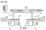
- step 3A shows an assembly process of a product (work)
- step 3B shows a painting process of the assembled product
- step 3C shows an inspection process of the painted product.
- control system data data for actually controlling the device
- control system data data for actually controlling the device
- the network 13 and the network 14 at a higher level are also called “corporate network”, and data for monitoring, managing, and controlling production activities at a production line / factory (hereinafter, "information system data"). (Sometimes collectively referred to as) to provide information-related communications.
- protocols and frameworks corresponding to such differences in required characteristics are adopted.
- EtherNet / IP registered trademark
- EtherCAT registered trademark
- the protocol of the network 11 (first protocol) and the protocol of the network 110 (second protocol) may be the same or different.
- each of the plurality of control devices 2A, 2B, and 2C connected to the network 11 transmits and receives data to and from one or more field devices 90 connected via the network 110.
- the control device 2 has a process of collecting data (input data) collected or generated by the field device 90 (input process) and a process of generating data (output data) such as a command to the field device 90 (output data). Arithmetic processing) and processing (output processing) of transmitting the generated output data to the target field device 90 are executed.
- control device 2 has a timer that defines the timing of data transmission and is time-synchronized with each other between the subjects (that is, one or a plurality of field devices 90) to which data is transmitted and received.
- the time is not synchronized between the plurality of control devices 2, for example, the field device 90 connected to one control device 2 and the field device 90 connected to another control device 2 The time cannot be synchronized between them. As a result, the timings of the input / output refresh processes may not match, and it becomes difficult to operate a plurality of field devices 90 connected to different control devices 2 in cooperation with each other.
- the timers of the plurality of control devices 2 are time-synchronized with each other. As a result, it is possible to realize coordinated control of a plurality of field devices 90 connected to different control devices 2, that is, between different processes.
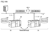
- FIG. 3 is a schematic diagram showing a network configuration example of the control system 1 according to the present embodiment.
- the control system 1 shown in FIG. 3 includes a plurality of control devices 2A, 2B and 2C, and a plurality of field devices 90A to 90I.
- the control system 1 employs a network in which at least some control devices are daisy-chained.
- Each of the control devices 2A, 2B and 2C functions as a master that manages data transmission within the corresponding network 110.
- the field devices 90A to 90I function as slaves that perform data transmission in accordance with a command from the corresponding master.
- the control devices 2A, 2B and 2C are connected to the control level network 11 (upper network).
- a device / line management device 190 is connected to the network 11.
- Field devices 90A, 90B, and 90C are sequentially connected to the network 110 connected to the control device 2A by a daisy chain, and field devices 90D, 90E, and 90F are daisy chained to the network 110 connected to the control device 2B.
- Field devices 90G, 90H, and 90I are sequentially connected by a daisy chain to the network 110 which is sequentially connected by a chain and is connected to the control device 2C.
- control device 2 and one or a plurality of field devices 90 can all be regarded as communication devices having a data transmission function.
- the control device 2 and one or a plurality of field devices 90 receives data transmitted on the network from a communication device connected adjacently, the data is required. It has a function of transmitting to another communication device connected adjacently according to the above.
- the transmission / reception timing is synchronized between the plurality of communication devices connected to the network 110, that is, the control device 2 and the one or the plurality of field devices 90 (time synchronization in the figure). Equivalent to (3)).
- each of the control device 2 and one or the plurality of field devices 90 includes a timer (or a counter that is synchronously incremented or decremented) that is time-synchronized with each other.
- Each of the controller 2 and one or more field devices 90 determines the timing of data transmission or reception according to their time-synchronized timers or counters.
- timing represents the concept of time, time, or time when some event occurs.
- time synchronization means that the timers, time data, etc. of each other are synchronized.
- timers 101A, 101B and 101C correspond to counter OC1 (see FIG. 1), respectively, and timers 102A, 102B and 102C correspond to counter DC2 (see FIG. 1), respectively.
- time synchronizations (1), (2) and (3) shown in FIG. 1 will be described more specifically with reference to FIG.
- the control device 2A includes a timer 102A, and the field devices 90A, 90B, and 90C include timers 91A, 91B, and 91C, respectively.
- the timer 102A of the control device 2A functions as a master, and the timers 91A, 91B, 91C of the field devices 90A, 90B, 90C synchronize the timing with reference to this master. For example, a value based on the timer value of the timer 102A is set in the timers 91A, 91B, 91C.
- the control device 2B has a timer 102B, and the field devices 90D, 90E, 90F have timers 91D, 91E, 91F, respectively.
- the timer 102B of the control device 2B functions as a master, and the timers 91D, 91E, 91F of the field devices 90D, 90E, 90F synchronize the timing with reference to this master. For example, values based on the timer value of the timer 102B are set in the timers 91D, 91E, and 91F.
- the control device 2C has a timer 102C, and the field devices 90G, 90H, 90I have timers 91G, 91H, 91I, respectively.
- the timer 102C of the control device 2C functions as a master, and the timers 91G, 91H, 91I of the field devices 90G, 90H, 90I synchronize the timing with reference to this master. For example, values based on the timer value of the timer 102C are set in the timers 91G, 91H, and 91I.
- each of the control devices 2A, 2B, and 2C functions as a master that manages data transmission in the corresponding network 110, and the field device 90 connected to each control device 2 transmits data according to a command from the master. Acts as a slave to do. By synchronizing the timers with each other between the master and the slave, it is possible to match the data transmission timing and the like between the control device 2 constituting the network 110 and the field device 90.
- the control device 2A further has a timer 101A that is time-synchronized with the timer 102A.
- the control device 2B further has a timer 101B that is time-synchronized with the timer 102B.
- the control device 2C further has a timer 101C that is time-synchronized with the timer 102C (corresponding to the time synchronization (2) in the figure).
- any of the timers 101A, 101B and 101C can function as a master of the entire control system 1.
- the timer 101A of the control device 2A is set as the master, and the timers of the control devices 2B and 2C synchronize the time with this master.
- the time can be synchronized with each other between the plurality of control devices 2A, 2B and 2C (corresponding to the time synchronization (1) in the figure).
- each of the plurality of control devices 2A, 2B and 2C has an inter-device timer (timers 101A, 101B and 101C) whose time is synchronized with each other among the plurality of control devices 2A, 2B and 2C, and the network 110. It has inter-device timers (timers 102A, 102B and 102C) that are time-synchronized with one or more field devices 90 connected via the inter-device timer, and the inter-device timer and the inter-device timer are time-synchronized with each other. ..
- timer 102A time-synchronized between the control device 2A and the field devices 90A, 90B, 90C and the device time-synchronized between the control device 2B and the field devices 90D, 90E, 90F.
- the timer (timer 102B) and the inter-device timer (timer 102C) whose time is synchronized between the control device 2C and the field devices 90G, 90H, and 90I are time-synchronized with each other.
- FIG. 2 has described a configuration example in which the timer of any of the control devices 2 is set as the master, the time acquired from the outside via the network 11 may be used as the master, or the device / line management device 190.
- the timer of an external device such as may be used as a master.
- FIG. 4 is a schematic diagram showing data communication processing of the control system 1 according to the present embodiment.
- data is exchanged between the control device 2A connected to the network 110 and the plurality of field devices 90A to 90C according to a predetermined system cycle.
- the data collected from the field device 90 by each control device 2 by the input processing and the output data generated by the arithmetic processing according to a predetermined system cycle. Etc. are exchanged.
- the field device 90 connected to the control device 2A, the field device 90 connected to the control device 2B, and the field device 90 connected to the control device 2C can be operated in cooperation with each other. That is, the field equipment 90 can be operated in cooperation between different processes.
- communication on the network 11 is also referred to as "upper network (NW) communication".
- the timing at which the transmission of data in the lower network communication should be started is determined based on the timers that are time-synchronized with each other among the plurality of control devices 2A, 2B and 2C. ..
- the timing of exchanging data with the field device 90 can be matched between the plurality of control devices 2A, 2B and 2C, and as a result, the field device 90 can be used between different processes.
- the control timing can be synchronized.
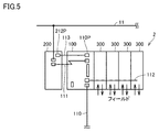
- FIG. 5 is a schematic view showing a configuration example of a unit of the control device 2 according to the present embodiment.
- the control device 2 included in the control system 1 includes a CPU (Central Processing Unit) unit 100 (hereinafter referred to as a CPU unit 100), one or more functional units 200, and one or more functions. Includes unit 300.
- the number of functional units 300 included in the control device 2 is four, but it may be one or two or more, and the number of functional units 200 included in the control device 2 is one, but two or more. It may be there.
- the CPU unit 100 connects one or more functional units 200 to the data bus 111 via the signal line 113. Further, the CPU unit 100 connects one or a plurality of functional units 300 via the data bus 112.
- the data bus 111 is, but is not limited to, an I / O serial interface bus that complies with, for example, PCIe (PCI Express).
- the signal line 113 is an optical fiber cable or an electrical signal cable, and transmits a time synchronization signal 130 which is a trigger signal.
- the CPU unit 100 has a program execution unit that executes a program created according to the control target. More specifically, the CPU unit 100 corresponds to an arithmetic processing unit that executes a system program and various user programs.
- the functional unit 200 carries out communication processing or information processing.
- the functional unit 200 includes an interface for connecting the data bus 111 and a signal port 212P for connecting the signal line 113.
- the functional unit 200 is arranged so as to mediate between the network 11 and the control device 2, so that the CPU unit 100 communicates data with a device connected to the network 11 via the functional unit 200. It can be carried out. Further, by connecting the signal line 113 between the signal port 110P of the CPU unit 100 and the signal port 212P of the functional unit 200, the CPU unit 100 and the functional unit 200 transmit the time synchronization signal 130 via the signal line 113. Receive.
- the functional unit 200 monitors the access to the CPU unit 100 from the Internet such as the network 14, and the access to the CPU unit 100 from other devices in the network 11, and the occurrence of some security event. Is detected, the inside or outside of the control device 2 is notified of the detected security event.
- the information processing performed by the functional unit 200 is not limited to the security monitoring process.
- the functional unit 300 functions as a so-called I / O unit that exchanges signals with equipment and devices to be controlled such as a field device 90 and various devices (sensors, actuators, etc.) arranged therein. Be prepared. Specifically, the functional unit 300 outputs the command value calculated by the CPU unit 100 to the field, or collects the input value from the field.
- the functional unit 300 includes, for example, a DI (Digital Input) module that receives a digital signal from a control target, a DO (Digital Output) module that outputs a digital signal to the control target, and an AI (AI) that receives an analog signal from the control target.
- DI Digital Input
- DO Digital Output
- AI AI
- the functional unit 300 may include a controller equipped with special functions such as PID (Proportional Integral Derivative) control and motion control.
- PID Proportional Integral Derivative
- the functional unit 200 or the functional unit 300 can be provided as an expansion unit that can be detachably attached to the CPU unit 100.
- FIG. 6 is a block diagram showing a hardware configuration example of the CPU unit 100 included in the control device 2 according to the present embodiment.
- the CPU unit 100 includes a processor 102, a chipset 104, a main storage device 106, a secondary storage device 108, a higher-level network controller 105, a USB (Universal Serial Bus) controller 107, a memory card interface 114, and the like. Includes local bus controllers 120 and 122, field network controllers 118, counter 126, RTC (Real Time Clock) 128, and signal port 110P.
- a processor 102 includes a processor 102, a chipset 104, a main storage device 106, a secondary storage device 108, a higher-level network controller 105, a USB (Universal Serial Bus) controller 107, a memory card interface 114, and the like.
- the processor 102 is composed of a CPU, an MPU (microprocessor unit), a GPU (Graphics Processing Unit), etc., and reads various programs stored in the secondary storage device 108, expands them in the main storage device 106, and executes them. , Control according to the control target, and various processes as described later are realized.
- the secondary storage device 108 is composed of, for example, a non-volatile storage device such as an HDD (Hard Disk Drive) or an SSD (Solid State Drive).
- the main storage device 106 is composed of a volatile storage device such as a DRAM (Dynamic Random Access Memory) or a SRAM (Static Random Access Memory).
- the chipset 104 realizes the processing of the CPU unit 100 as a whole by controlling the processor 102 and each device.
- the secondary storage device 108 in addition to the system program for realizing the basic functions, the user program created according to the manufacturing device and equipment to be controlled is stored. Further, the secondary storage device 108 also stores a time series database as described later.
- the upper network controller 105 exchanges data with the manufacturing execution system 400 or a device on the cloud (see FIG. 1) via the upper network 11.
- the USB controller 107 controls the exchange of data with the support device 500 via the USB connection.
- the memory card interface 114 is configured so that the memory card 116 can be attached and detached, data can be written to the memory card 116, and various data (user programs, trace data, etc.) can be read from the memory card 116. ing.
- the counter 126 is used as a time reference for managing the execution timing of various processes in the CPU unit 100.
- the counter 126 typically increments or decrements the counter value at predetermined intervals.
- the CPU unit 100 may be mounted as a counter 126 by using a high precision event timer (HPET: High Precision Event Timer) or the like, which is a hardware timer arranged on the system bus that drives the processor 102. Alternatively, it may be mounted using a dedicated circuit such as ASIC (Application Specific Integrated Circuit) or FPGA (Field-Programmable Gate Array).
- HPET High Precision Event Timer
- ASIC Application Specific Integrated Circuit
- FPGA Field-Programmable Gate Array
- the RTC128 is a kind of counter having a timekeeping function, and provides the current time to the processor 102 or the like.
- the local bus controller 122 is an interface for exchanging data with the functional units 300-1, 300-2, ... Which can be connected to the CPU unit 100.
- the local bus controller 122 uses a counter 123 as a time reference for managing timing between the functional units 300-1, 300-2, ..., Which are other devices connected via the data bus 112. Have.
- each of the functional units 300-1, 300-2, ... Has a counter 125 used as a time reference for managing timing between the local bus controller 122 and the other functional units 300. ..
- the same configuration as the counter 126 described above can be adopted.
- the field network controller 118 controls the exchange of data with other devices including the field device 90 via the network 110.
- the field network controller 118 has a counter 119 used as a time reference for managing timing with other devices.
- the local bus controller 120 is an interface for exchanging data with the functional units 200-1, 200-2, ... Which can be connected to the CPU unit 100.
- the local bus controller 120 uses a counter 121 as a time reference for managing timing between the functional units 200-1, 200-2, ..., Which are other devices connected via the data bus 111. Have.
- each of the functional units 200-1, 200-2, ... Has a counter 213 used as a time reference for managing the timing with the local bus controller 120.
- the counter 121 and the counter 213 can adopt the same configuration as the counter 126 described above.
- each device on the network 110 also has a counter used as a time reference for managing the timing with the field network controller 118.
- the same configuration as the counter 126 described above can be adopted.
- the field network controller 118 functions as a communication master for performing constant periodic communication via the network 110, and is the difference between the counter value indicated by the counter of each device connected to the fieldbus and the counter value indicated by the counter 119. Is sequentially monitored, and if necessary, a synchronization signal for instructing correction is output to the device in which the counter value is deviated. As described above, the field network controller 118 has a synchronization management function for giving a command to the device to match the counter value indicated by the counter of the device with the counter value indicated by the counter 119.
- a signal line 113 that transmits a time synchronization signal 130 is connected to the signal port 110P.
- the counter 119, the counter 121, and the counter 123 are synchronized with the counter 126.
- FIG. 6 shows a configuration example in which the necessary functions are provided by the processor 102 executing the program, and the CPU unit 100 uses dedicated hardware for some or all of these provided functions. It may be implemented using a circuit (for example, ASIC (Application specific Integrated Circuit) or FPGA (Field-Programmable Gate Array)). Alternatively, the main part of the CPU unit 100 may be realized by using hardware that follows a general-purpose architecture (for example, an industrial personal computer based on a general-purpose personal computer). In this case, the virtualization technology may be used to execute a plurality of OSs (Operating Systems) having different uses in parallel, and to execute necessary applications on each OS.
- OSs Operating Systems
- the CPU unit 100 and the support device 500 are configured as separate bodies, but a configuration is adopted in which all or part of these functions are integrated into a single device. You may.
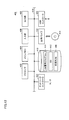
- FIG. 7 is a block diagram showing a hardware configuration example of the functional unit 200 included in the control device 2 according to the present embodiment.
- functional unit 200 includes processor 202, chipset 204, main memory 206, storage 208, inter-unit interface 210, network interface 220, and signal port 212P.
- a signal line 113 that transmits a time synchronization signal 130 is connected to the signal port 212P.
- the processor 202 is composed of a CPU, an MPU, a GPU, and the like. Like the CPU unit 100 described above, the functional unit 200 has one or more processors 202 and / or a processor 202 having one or more cores. By controlling the processor 202 and peripheral elements, the chipset 204 realizes the processing of the functional unit 200 as a whole.
- Chipset 204 includes a signal generator 26, which is a circuit element that generates a time synchronization signal 130. The time synchronization signal 130 from the signal generator 26 is sent to the signal line 113 via the signal port 212P.
- the main memory 206 is composed of a volatile storage device such as a DRAM or SRAM.
- the storage 208 is composed of, for example, a non-volatile storage device such as a flash memory.
- the processor 202 reads various programs stored in the storage 208, expands them in the main memory 206, and executes them to realize processing such as monitoring of security events.
- the storage 208 stores a system program 22 and a user program 20 for realizing basic processing. Further, the storage 208 has a storage area 21 for storing time-series data of the observed values collected by the functional unit 200.
- the user program 20 includes a time synchronization program 23 that controls time synchronization between units and a security program 24 for security monitoring processing.
- the time synchronization program 23 includes a correction program 25 for realizing the correction unit 20A or the correction unit 20B described later by being executed.
- the security program 24 performs security monitoring processing based on security settings that prescribe rules and the like defined in advance by the operator or administrator of the control device 2, collects observation values based on the processing results, and takes time. It is stored in the storage area 21 as series data.
- the inter-unit interface 210 connects the data bus 111.
- the inter-unit interface 210 exchanges data with the CPU unit 100 via the data bus 111.
- the inter-unit interface 210 includes a data communication circuit 211 including a controller (Tx / Rx CTRL) and a buffer for transmitting and receiving data to and from the CPU unit 100 or another functional unit 200, and a counter 213.
- a controller Tx / Rx CTRL
- a buffer for transmitting and receiving data to and from the CPU unit 100 or another functional unit 200, and a counter 213.
- the network interface 220 includes a controller (Tx / Rx CTRL) 222 and a buffer 226 for exchanging data via the network 11.
- the buffer provided in the inter-unit interface 210 and the network interface 220 corresponds to a storage unit that temporarily stores data to be transmitted and data received.
- the counter 213 has the same configuration as the counter 126 (see FIG. 6) included in the CPU unit 100.
- the network interface 220 and the inter-unit interface 210 of the functional unit 200 may be composed of a NIC (Network Interface Card). Further, FIG. 7 shows a configuration example in which necessary processing is realized by executing a program by the processor 202, and a part or all of the processing provided is a dedicated hardware circuit (for example,). , ASIC, FPGA, etc.).
- FIG. 8 is a block diagram showing a hardware configuration example of the functional unit 300 included in the control device 2 according to the present embodiment.
- the functional unit 300 provides various functions necessary for realizing control of various machines or equipment by the control system 1. More specifically, each of the functional units 300 includes a functional module 157, an I / O interface 159, and a communication circuit 161.
- the function module 157 is a part that executes the main processing of each function unit 300, and controls the collection of field information from the machine or equipment to be controlled and the output of a command signal to the machine or equipment to be controlled.
- the I / O interface 159 is a circuit that mediates the exchange of signals with a machine or equipment to be controlled.
- the communication circuit 161 processes the data sequentially transferred to the data bus 112. That is, when the communication circuit 161 receives some data via the data bus 112, the communication circuit 161 processes the received data and then transmits the communication data to the functional unit 300 located next on the data bus 112.
- the communication circuit 161 provides a function of relaying such data.
- the communication circuit 161 includes transmission / reception ports 162, 164, a controller 166 for transmission / reception, and a counter 168.
- the transmission / reception ports 162 and 164 are parts that are physically connected to the data bus 112, and perform processing such as reception and reproduction of data transmitted on the data bus 112 in accordance with a command from the controller 166 to perform data. Achieve sequential transfer of.
- the controller 166 performs data processing such as reading data transferred on the data bus 112 and changing the data.
- the counter 168 generates a clock that serves as a reference for timing such as command output by the controller 166 or processing execution by the function module 157.
- a counter using a real-time clock can be adopted, but in the present embodiment, a free-run counter that counts up (increments) at a predetermined cycle can be applied.
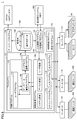
- FIG. 9 is a block diagram showing a software configuration example of the CPU unit 100 according to the present embodiment.
- the CPU unit 100 includes a PLC engine 150, a time series database 180, an upper connection program 192, and a gateway program 194.
- the PLC engine 150 typically has an execution environment for various programs in which the processor 102 of the CPU unit 100 reads out the system program stored in the secondary storage device 108, deploys it to the main storage device 106, and executes it. Is provided, and various programs can be executed in the execution environment.
- the PLC engine 150 includes a control program 152, a variable management program 160, a scheduler program 170, an input program 172, an output program 174, and a time synchronization program 177.
- the variable management program 160, the scheduler program 170, the input program 172, and the output program 174 may be implemented as a part of the system program. In this case, each function provided by these programs may be provided by a single system program.
- the control program 152 is typically composed of a user program 154, a database writing program 156, and a serialization communication program 158.
- the user program 154 corresponds to a main part that provides a control calculation function, and can be arbitrarily configured according to a manufacturing device or equipment to be controlled by the CPU unit 100.
- the user program 154 can be defined by, for example, ladder logic using a function block or the like.
- the database writing program 156 is called by the instruction specified in the user program 154 and writes the specified data to the time series database 180.
- the serialization communication program 158 performs serialization processing on the data written from the database writing program 156 to the time series database 180. More specifically, the serialization communication program 158 executes a process (serialization) of converting time series data into a storeable byte string. The target data is converted into a predetermined byte string by the serialization process and then stored in the time series database 180. It should be noted that the serialization process does not necessarily have to be performed according to the speed of writing data to the time series database 180, the data capacity, and the like. That is, the serialized communication program 158 has an optional configuration.
- the variable management program 160 manages the values available in the PLC engine 150 in the form of variables. More specifically, the variable management program 160 includes system variables indicating the state of the CPU unit 100 and device variables indicating values held by various devices connected to the CPU unit 100 via the local bus or field bus. , A user variable indicating a value held by the user program 154 executed by the CPU unit 100 is managed.
- the input program 172 provides a function of acquiring input data from various devices connected to the CPU unit 100 via a local bus or a field bus.
- the output program 174 outputs a command value (output data) calculated by the user program 154 executed in the CPU unit 100 to a target device connected via the data bus 112 or the network 110.
- the time synchronization program 177 connects to the CPU unit 100, the functional unit 200 connected to the data bus 111, the functional unit 300 connected to the data bus 112, and the network 110 when the control program in the CPU unit 100 is executed.
- the time synchronization with the field device 90 to be performed is realized.
- the time synchronization program 177 includes a correction program 178 for appropriately correcting a timer managed for time synchronization.
- the correction unit 10B described later is realized. The correction process performed by the correction unit 10B will be described later.
- the scheduler program 170 manages resource allocation, execution timing, etc. for processes or tasks of the CPU unit 100.
- a process or task includes a process or task that can be generated by executing the control program 152, the variable management program 160, the input program 172, the output program 174, the time synchronization program 177, and the like by the CPU unit 100. ..
- the time-series database 180 is typically located in the main storage 106 or the secondary storage 108, and has the function of storing data and responds to the specified data in response to an external request (query). It is equipped with a search function.
- the time series database 180 stores the time series data 182 written by the database writing program 156. That is, the time series database 180 stores at least a part of the input data, the output data, the calculation data calculated in the control calculation by the control program 152, the manufacturing data, and the event data in the time series.
- Such input data and output data include data received by the CPU unit 100 from the functional unit 300 and data transmitted by the CPU unit 100 to the functional unit 300.
- the event data may include data related to security monitoring received by the CPU unit 100 from the functional unit 200.
- the upper connection program 192 exchanges data with an external device connected to the upper network 13 such as the manufacturing execution system 400.
- input data and calculation data can be output from the CPU unit 100 to the manufacturing execution system 400, and manufacturing information can be received from the manufacturing execution system 400.
- the higher-level connection program 192 provides a manufacturing data acquisition function for acquiring manufacturing data from the manufacturing execution system 400 associated with the controlled object.
- the manufacturing execution system 400 has a time series DB 450.
- the database connection program 193 may be provided in place of the upper connection program 192 or as a part of the upper connection program 192.
- the database connection program 193 may, for example, send a query such as SQL to a relational database and execute a process of receiving a response.
- the time-series data 182 of the time-series database 180 in the CPU unit 100 can be transferred to the manufacturing execution system 400 and stored in the time-series DB 450. Details of the time-series data output to the manufacturing execution system 400 by the database connection program 193 will be described later.
- the gateway program 194 communicates with the device on the cloud.
- the time series data 182 of the time series database 180 is provided to the device that provides the IoT service on the cloud.
- the gateway program 194 acquires data of a specified type from the time series database 180 at a specified cycle and outputs the data as time series data.
- the time-series data output to the IoT service providing device by the gateway program 194 can have, for example, the same configuration as the time-series data output to the manufacturing execution system 400 by the database connection program 193.
- the input program 172 of the CPU unit 100 acquires input data from a field device 90 such as a sensor via the data buses 111, 112 and / or the network 110.
- the upper connection program 192 of the CPU unit 100 acquires manufacturing data from the manufacturing execution system 400.
- the variable management program 160 manages these acquired input data and manufacturing data as variables.
- the user program 154 executes a predetermined control operation while referring to the system variables, device variables, and user variables managed by the variable management program 160, and outputs the execution result (output data) to the variable management program 160. To do.
- the output program 174 outputs the output data calculated by the control calculation of the user program 154 as control output to the field device 90 such as an actuator via the data bus 112 and / or the network 110.
- the database writing program 156 writes the specified observation values among the variables managed by the variable management program 160 into the time series database 180.
- the upper connection program 192 uses the values of the specified variables among the variables managed by the variable management program 160 and / or the specified data of the time series data 182 stored in the time series database 180 in a time series. It is output as data to the manufacturing execution system 400.
- the gateway program 194 uses the values of the specified variables among the variables managed by the variable management program 160 and / or the specified data among the time series data 182 stored in the time series database 180 as time series data. Is output to the IoT service.
- the IoT service providing device provides, for example, a service that performs behavior analysis based on time-series data from the CPU unit 100 and performs predictive maintenance of equipment and devices to be controlled.
- the control device 2 has a function of synchronizing the time and the counter (hereinafter, also referred to as “time synchronization” and “counter synchronization”, respectively).
- time is intended to indicate a certain point in the flow of time, and is defined by using a unit such as hour, minute, or second.
- the "counter” includes a value for controlling timing in the control device 2 and related devices, and is basically a value that is incremented or decremented by a predetermined value every predetermined unit time (hereinafter referred to as "counter”).
- the value indicated by the counter is also referred to as "counter value”).
- the counter value corresponds to the value of the timer, and represents, for example, a 64-bit length integer value capable of expressing the order of nanoseconds, without limitation.
- the synchronization accuracy of the time is inferior to the synchronization accuracy of the counter. Therefore, in the present embodiment, between the units constituting the control device 2 and between each unit and another device including the field device 90. In between, time synchronization using a counter value is adopted.
- FIGS. 10A and 10B are diagrams schematically showing an example of a configuration for time synchronization managed by the control device 2 according to the present embodiment.
- a configuration for each control device 2 to acquire a counter value of the master clock from the network 11 and a configuration for realizing time synchronization using the time synchronization signal 130 as a trigger will be described.
- the time synchronization signal 130 is generated by the signal generator 26 (see FIG. 7) of the functional unit 200 and transmitted to the signal line 113.
- the configuration for realizing such time synchronization is, for example, a case where the master clock of TSN (Time-Sensitive Networking) is provided to the control device 2 via the network 11 (see FIG. 10A), and a case where the control device 2 is provided with the network 11.
- TSN Time-Sensitive Networking
- EtherCAT registered trademark: Ethernet for Control Automation Technology
- the standard of the master clock provided to the control device 2 via the network 11 is not limited to these, and may be, for example, IECEE1588.
- the TSN master clock 191A is provided by, for example, the device / line management device 190 on the network 11.
- the master clock 191A indicates, for example, an absolute time managed by a time synchronization server located on the Internet.
- the master clock 191A may be another device on the network 11.
- the functional unit 200 includes a synchronization processing unit 200A when the time synchronization program 23 is executed.
- the synchronization processing unit 200A communicates with the device / line management device 190 via the network interface 220 and refers to the master clock 191A. Further, the synchronization processing unit 200A has a counter DC1 and a counter OC1.
- the synchronization processing unit 200A may include a correction unit 20A that performs correction processing for the counter value.
- the counter DC1 and the counter OC1 correspond to, for example, the counter 213 (see FIG. 6 or 7).
- the CPU unit 100 includes a synchronization processing unit 100A by executing the time synchronization program 177.
- the synchronization processing unit 100A includes a correction unit 10B, a storage area 10C, a counter DC2, and a counter OC2.
- the counter DC2 corresponds to the counter 119 and the counter 123 (see FIG. 6).
- the counter DC2 also corresponds to a counter (counter 126 or the like in FIG. 6) referred to by the scheduler program 170 to schedule the execution timing of the control program 152 or the like.
- the counter OC2 corresponds to the counter 121 (see FIG. 6).
- the counters OC1 and OC2 represent counters by Ordinary Clock, and counters DC1 and DC2 represent counters by Distributed Clock.
- the synchronization processing unit 200A uses the function of the device / line management device 190 as a time synchronization server to correct the transmission delay of the network 11 or the like when acquiring the time of the master clock 191A. As a result, the synchronization processing unit 200A can acquire a more accurate time from the master clock 191A.
- the synchronization processing unit 200A sets a counter value based on the time acquired from the master clock 191A in the counter OC1.
- the synchronization processing unit 200A periodically acquires the time of the master clock 191A from the device / line management device 190 and sets it in the counter OC1.
- the synchronization processing unit 200A can synchronize the counter OC1 with the master clock 191A.
- the functional unit 200 functions as a time synchronization server with respect to the CPU unit 100. That is, the synchronization processing unit 200A periodically transmits the counter value of the counter OC1 to the data bus 111. As a result, the functional unit 200 can provide the CPU unit 100 connected to the data bus 111 with a counter value synchronized with the master clock 191A (that is, a counter value of the counter OC1).
- the synchronization processing unit 100A of the CPU unit 100 receives the timer value of the counter OC1 via the data bus 111 at startup, and sets the received timer value in the counter OC2. After that, the synchronization processing unit 100A periodically updates (increments or decrements) the counter value of the counter OC2 in synchronization with the output from the internal hardware circuit, and sets the updated value in the counter DC2. As a result, the counter value of the counter DC2 is periodically updated.
- the synchronization processing unit 100A synchronizes the counter OC2 and the counter DC2 with the counter OC1 synchronized with the master clock 191A, so that the counter DC2 can be synchronized with the master clock 191A.
- the CPU unit 100 performs program scheduling based on the synchronization between the master clock 191A and the counter described above. This point will be described with reference to FIGS. 6 and 9. More specifically, the scheduler program 170 performs scheduling of the control program 152 and the like with reference to the counter 126. Further, the input program 172 and the output program 174 perform time synchronization with each device with reference to the counter 119 and the counter 123 synchronized with the counter 126. As a result, scheduling of the control program 152 and the like in the CPU unit 100 and time synchronization between each device connected to the control device 2 and the control device 2 can be performed with reference to the master clock 191A. As a result, scheduling of a control program or the like in the CPU unit 100 and input / output between each device connected to the control device 2 and the control device 2 can be performed in synchronization with the master clock 119A.
- the synchronization processing unit 100A corrects the counter value of the counter DC2 by using a value for reducing the synchronization deviation (hereinafter, also referred to as an adjustment value D). Specifically, when the correction unit 10B receives the time synchronization signal 130 from the signal line 113, the correction unit 10B performs a correction process including a latch process.
- the correction unit 10B latches (acquires) the counter value of the counter DC2, and stores the latched counter value LDC2 in the storage area 10C. Further, in the latch processing, the correction unit 10B latches (receives) the counter value of the counter OC1 transmitted via the data bus 111, and stores the latched counter value LOC1 in the storage area 10C.
- the adjustment value D (positive value or negative value) is added to the latched counter value, and the added value is set in the counter DC2.
- the adjustment value D may be added to the counter value of the counter DC2 at a specified frequency.
- the above adjustment value D is fixed or variable.
- the variable value may include a value determined according to the magnitude of the difference between the latched counter values LOC1 and LDC2. Further, the value of "N" may be fixed or variable, and the variable value may include, for example, a value determined according to the magnitude of the adjustment value D.
- the correction unit 10B detects a tendency of a change (drift-like change) in the difference between the counter values LOC1 and LDC2, which is calculated each time the time synchronization signal 130 is received, and adjusts the above adjustment value according to the change tendency.
- the value of D or "N” may be determined. That is, the value of the above adjustment value D or "N” is determined so that the synchronization deviation calculated each time the time synchronization signal 130 is received becomes small, that is, the difference in synchronization deviation converges to a predetermined value. .. For example, by increasing the adjustment value D or decreasing the value of "N" as the fluctuation range is larger, the synchronization deviation can be reduced and the synchronization deviation can converge to a predetermined value earlier.
- the initialization of the counter DC2 by setting the above adjustment value D to the value of the counter DC2 may be included.
- the timing at which the correction process is performed may be the time when the time synchronization signal 130 is received, or may be after a predetermined time has elapsed from the time when the time synchronization signal 130 is received.
- the unit of the source of the time synchronization signal 130 is not limited to the functional unit 200, and may be another unit provided in the control system 1 of FIG.
- a predetermined trigger signal generator (not shown) provided in the control system 1 of FIG. 1, or any control device 2 (CPU unit 100 or functional unit 200, 300 (see FIG. 5) of the control device 2), or The device / line management device 190 may be used.
- the time synchronization signal 130 is output periodically, for example, every 1 ms, but the method is not limited to the method of periodically outputting the signal 130. For example, when the counter value of the counter OC1 of the synchronization processing unit 200A of the functional unit 200 becomes equal to a certain indicated value, the unit of the source of the time synchronization signal 130 may output the time synchronization signal 130.
- the time is acquired from the master clock 191A provided by the TSN, but the acquisition route of the master time for time synchronization is not limited to the TSN.
- it may be acquired from the master clock 191B of EtherCAT.
- EtherCAT the master clock 191B is synchronized with the absolute time.
- counters DC1 and DC2 are used for time synchronization.
- the synchronization processing unit 200B of the functional unit 200 periodically acquires the time of the master clock 191B after correcting the propagation delay.
- the synchronization processing unit 200B sets a counter value indicating the acquired time in the counter DC1.
- the synchronization processing unit 200B periodically reads the counter value of the counter DC1 and transmits it to the data bus 111.
- the counter DC1 corresponds to the counter 213 (see FIG. 6).
- the counter DC2 corresponds to the counters 119, 121 and 123 (see FIG. 6) and the counters referred to by the scheduler program 170 in FIG. 9 for scheduling the execution timing of the control program 152 and the like (counter 126 and the like in FIG. 6). To do.
- the synchronization processing unit 100B of the CPU unit 100 sets the counter value received via the data bus 111 to the counter DC2. After that, the value of the counter DC2 is updated (incremented or decremented) in synchronization with the output of the internal hardware circuit. As a result, the count value of the counter DC2 is periodically updated. Further, when the time synchronization signal 130 is received via the signal line 113, the correction unit 10B of the synchronization processing unit 100B latches the counter value received via the data bus 111, and sets the latch counter value LDC1 as the storage area 10C. Store in. Further, when the correction unit 10B receives the time synchronization signal 130, it latches the counter value of the counter DC2 and stores it in the storage area 10C as the latch counter value LDC2.
- the adjustment value D used for the correction may include a value determined according to the magnitude of the difference (synchronization deviation) between the latch counter values LDC1 and LDC2.
- the correction unit 10B detects a tendency of a change (drift-like change) in the difference between the latch counter values LDC1 and LDC2 calculated each time the time synchronization signal 130 is received, and adjusts the above according to the change tendency.
- a value of value D or "N” may be determined.
- the value of the adjustment value D or "N” may be determined so that the difference calculated each time the time synchronization signal 130 is received becomes small, that is, the difference converges to a predetermined value.
- initialization of the counter DC2 may be included by setting the above adjustment value to the value of the counter DC2.
- the time for performing the correction process may be the same as that of FIG. 10A.
- the time synchronization signal 130 may be output to the signal line 113 when the counter value of the counter DC1 becomes equal to a certain indicated value.
- the correction process is not limited to the configuration performed by the correction unit 10B of the CPU unit 100, and may be performed by using the correction unit 20A and the storage unit 20C of the functional unit 200.
- the synchronization processing unit 100A of the CPU unit 100 periodically transmits the counter value of the counter DC2 to the data bus 111.
- the correction unit 20A receives the time synchronization signal 130 from the signal line 113, the correction unit 20A performs a latch process.
- the correction unit 20A latches (acquires) the counter value of the counter OC1 and latches (receives) the counter value of the counter DC2 transmitted via the data bus 111.
- the counter values latched in this way are stored in the storage unit 20C as latch counter values LOC1 and LDC2.
- the correction unit 20A calculates the difference in synchronization deviation between the latch counter values LOC1 and LDC2 of the storage unit 20C, determines the adjustment value D (positive value or negative value) so that the difference becomes small.
- the determined adjustment value D is added to the latch counter value LDC2.
- the correction unit 20A transfers the added latch counter value to the CPU unit 100 via the data bus 111.
- the CPU unit 100 sets the received latch counter value after addition in the counter DC2. As a result, the counter value of the counter DC2 of the CPU unit 100 is corrected for synchronization deviation.
- the correction unit 20B may perform the correction processing of the counter value of the counter DC2 of the CPU unit 100 by using the storage unit 20C.
- the synchronization processing unit 100B periodically transmits the counter value of the counter DC2 to the data bus 111.
- the correction unit 20B receives the time synchronization signal 130 from the signal line 113, the correction unit 20B performs a latch process.
- the correction unit 20B latches (acquires) the counter value of the counter DC1 and latches (receives) the counter value of the counter DC2 transmitted via the data bus 111.
- the counter values latched in this way are stored in the storage unit 20C as latch counter values LDC1 and LDC2.
- the correction unit 20B determines an adjustment value D such that the difference in synchronization deviation between the latch counter values LDC1 and LDC2 becomes small, and adds the determined adjustment value D to the latch counter value LDC2.
- the correction unit 20B transfers the added value to the CPU unit 100 via the data bus 111.
- the CPU unit 100 sets the received latch counter value LDC2 after addition to the counter DC2. As a result, the counter value of the counter DC2 of the CPU unit 100 is corrected for synchronization deviation.
- the first timer value (counter value of the counter OC1) indicated by the timer of the first unit (functional unit 200) is shown.
- the second timer value (timer value of the counter DC2) indicated by the timer of the second unit (CPU unit 100) are acquired via the data line (data bus 111), and the acquired timer is obtained. Based on the value, the synchronization shift between the timer of the first unit and the timer of the second unit is corrected. As a result, the timer (counter DC2) of the second unit (CPU unit 100) can be set to match the timer (counter OC1) of the first unit (functional unit 200).
- control system 1 may further include a unit 370 different from the CPU unit 100 and the functional unit 200, and cause the unit 370 to perform the correction process described above.
- the unit 370 can be connected to the signal line 113 and the data bus 111.
- the unit 370 includes a hardware processor, and the hardware processor executes a program to realize the correction unit 20A (or the correction unit 20B) or the correction unit 371 corresponding to the correction unit 10B.
- the correction unit 371 reads the counter value from the counter OC1 and the counter DC2 (or the counter DC1 and the counter DC2) via the data bus 111.
- the correction unit 371 corrects the count value of the counter DC2 by using the read counter value so that the synchronization deviation becomes small as described above.
- the corrected counter value is set in the counter DC2 via the data bus 111.
- the correction units 20A and 20B, the correction unit 10B, and the correction unit 371 shown in FIGS. 10A and 10B are examples of the adjusting means.
- the control device 2 or the control system 1 uses a dedicated hardware circuit (for example, ASIC or FPGA) to perform a part or all of the processing provided by the correction units 20A and 20B, the correction unit 10B, and the correction unit 371. May be implemented.
- each control device 2 using the time of the master clock 191A (or 191B), (i) time synchronization is realized between the units, and (ii) each unit and a device connected to the unit are realized. Time synchronization is realized between the two, and in the (iii) CPU unit 100, time synchronization for execution of the control program 152, the input program 172, and the output program 174 is realized by the scheduler program 170. Further, when each control device 2 performs time synchronization using the common master clocks 191A and 191B, (iv) time synchronization can be realized between different control devices 2, that is, between different processes.
- control system 1 is configured to include correction units 20A and 20B, correction units 10B, and correction unit 371, but may be configured to include at least one of these correction units.
- FIG. 11 is a diagram showing an example of a flowchart of the process according to the present embodiment.
- FIG. 11 includes a synchronization process and an observation value collection process.
- the processor 202 of the functional unit 200 performs processing by the synchronization processing unit 200A (or 200B).
- the processor 202 acquires the time from the master clock 191A (or 191B) and sets the timer value in the counter OC1 (or DC1) (step S1).
- the processor 202 determines whether it is time to transmit the time synchronization signal 130 (step S3). If it is determined that the time synchronization signal 130 is not the transmission time (NO in step S3), the process returns to step S1, but if it is determined that the transmission time has come (YES in step S3), the signal generator 26 generates the time synchronization signal 130. Output to the signal line 113 (step S5).
- the processor 202 periodically transmits the counter value of the counter OC1 (or DC1) to the data bus 111 (step S7).
- the transmission of this counter value is carried out regardless of the transmission of the time synchronization signal 130.
- the processor 101 performs processing by the synchronization processing unit 100A (or 100B). In the process of FIG. 11, a process of setting the counter OC2 and updating the counter value of the counter DC2 is performed.
- the processor 101 determines whether to receive the time synchronization signal 130 from the signal line 113 (step S25). While the time synchronization signal 130 is not received (NO in step S25), the process of step S25 is repeated.
- step S25 When the processor 101 determines that the time synchronization signal 130 has been received (YES in step S25), the processor 101 performs the counter value latch processing described above (step S27). The processor 101 determines whether it is time to perform the correction process by the correction unit 10B (step S29). For example, it is determined whether a predetermined time has elapsed since the time synchronization signal 130 was received. While it is determined that it is not time to perform the correction (NO in step S29), the process of step S29 is repeated.
- Step S31 When it is time for the processor 101 to perform the correction process, for example, when it is determined that a predetermined time has elapsed since the time synchronization signal 130 was received (YES in step S29), the correction process described above is performed by the correction unit 10B. (Step S31).
- the correction process includes calculation of the difference between the latched counter values (step S33), determination of the adjustment value D for correction (step S35), and change of the counter value of the counter DC2 using the adjustment value D (step S37). including.
- the processor 101 collects the observed values and stores them in the time series database 180 (step S41).
- the processor 101 reads the time-series data 182 of the time-series database 180 and transmits it to the manufacturing execution system 400 or the IoT service providing device on the cloud (step S43).
- a frame for transmitting the time series data 182 is generated and transmitted in the frame format (step S45).
- the manufacturing execution system 400 receives a frame of time series data 182 from the control device 2 (step S61) and stores it in the time series DB 450 (step S63).
- the correction for the time synchronization process is performed in the CPU unit 100, but as described above, the correction for the time synchronization process may be performed in the functional unit 200 in the same manner as in step S31.
- the functional unit 200 provided the counter value to the CPU unit 100 by periodically transmitting the counter value of the counter OC1 (or the counter DC1) to the data bus 111.
- the method of providing the counter value to the CPU unit 100 is not limited to this.
- the CPU 100 refers to (reads) the counter value of the counter OC1 (or counter DC1) of the functional unit 200 via the data bus 111. You may.
- FIG. 12 is a diagram showing a configuration example of the manufacturing execution system 400 according to the present embodiment.
- the manufacturing execution system 400 is realized by using hardware (for example, a general-purpose personal computer) that follows a general-purpose architecture.
- the manufacturing execution system 400 includes a processor 402, a main memory 404, an input unit 406, an output unit 408, a storage 410, an optical drive 412, and a USB controller for communicating with an external device. Includes 420 and a network controller 413 that connects networks 13 and 14. These components are connected via the processor bus 418.
- the processor 402 is composed of a CPU, a GPU, or the like, reads a program stored in the storage 410, expands it into the main memory 404, and executes it to realize various processes as described later.
- the main memory 404 is composed of a volatile storage device such as DRAM or SRAM.
- the storage 410 is composed of, for example, a non-volatile storage device such as an HDD or SSD.
- the storage 410 in addition to the OS 412 for realizing the basic functions, various programs for providing the functions as the manufacturing execution system 400 are stored.
- the various programs include a DB management program 411. Further, the storage 410 has an area for storing the time series DB 450.
- the input unit 406 is composed of a keyboard, a mouse, and the like, and receives user operations on the manufacturing execution system 400.
- the output unit 408 is composed of a display, various indicators, a printer, and the like, and outputs a processing result from the processor 402 and the like.
- the manufacturing execution system 400 has an optical drive 412, and from a recording medium 414 (for example, an optical recording medium such as a DVD (Digital Versatile Disc)) that non-transiently stores a computer-readable program, among the recording media 414.
- a recording medium 414 for example, an optical recording medium such as a DVD (Digital Versatile Disc)
- the program stored in is read and installed in the storage 410 or the like.
- FIG. 12 shows a configuration example in which the functions required as the manufacturing execution system 400 are provided by the processor 402 executing the program, and the manufacturing execution system 400 is a part of these provided functions or All may be implemented using a dedicated hardware circuit (eg, ASIC or FPGA).
- a dedicated hardware circuit eg, ASIC or FPGA
- FIG. 13 is a diagram showing a DB manager provided by executing the DB management program 411 of FIG.
- the DB manager 451 provided by executing the DB management program 411 by the processor 402 manages the time-series DB 450 (for example, DB generation, aggregation, editing, analysis, output, etc.). To do.
- FIGS. 14A and 14B are schematic views showing a processing example when the control device 2 according to the present embodiment transmits time series data to the manufacturing execution system 400.
- FIGS. 14A and 14B a case where the time synchronization process is not performed (see FIG. 14A) and a case where the time synchronization process is performed (see FIG. 14B) are shown in contrast.
- FIG. 15 is a diagram schematically showing a frame of time series data and aggregated data generated by the control device 2 according to the present embodiment.
- FIG. 15A shows a frame for storing the observation values collected by the control device 2B in the process 3B
- FIG. 15B shows a frame for storing the observation values collected by the control device 2A in the process 3A.
- FIG. 15 (C) shows an example of a time-series DB 450 that stores observation values aggregated by the DB manager 451.
- FIG. 14A shows a configuration in which the control devices 2A and 2B are connected to the manufacturing execution system 400 via the upper network 13. In the configuration shown in FIG. 14A, it is assumed that the time synchronization is not performed between the control device 2A and the control device 2B.
- Each time series data includes the observed values collected by the control devices 2A and 2B and the time associated with each observed value. Conversely, in the configuration shown in FIG. 14A, the control devices 2A and 2B can only add a time as information indicating the collection timing of each observed value. The time is managed by the control devices 2A and 2B, respectively, and the time synchronization is incomplete.
- the times do not completely match between the time-series data collected by the manufacturing execution system 400, so that the DB manager 451 aggregates (that is, integrates) the respective time-series data at the exact timing. ) Cannot be done.
- the control device 2A and the control device 2B are provided with the time-synchronized counter described above.
- the time series data frame transmitted from each of the control device 2A and the control device 2B is associated with the observation values collected in the steps 3A and 3B, and the time 452 indicating the timing of collecting each observation value (for example).
- the time obtained from the master clock) and the counter value 453 eg, the counter value of the counter DC2 can be included (see (A) in FIG. 15 and (B) in FIG. 15).
- the DB manager 451 can adjust the timing of the observed values included in the time series data by using the counter value 453 included in the time series data received from each of the control devices 2A and 2B. That is, even if the observed values are collected by different control devices 2 (different processes), they are aggregated and stored in the time series DB 450 with the time axes almost completely matched (see (C) in FIG. 15). , The aggregated data can be used for the analysis of observed values.
- the signal line and the adjusting means (10B, 20A, 20B) connected to the data line are provided.
- the adjusting means When the trigger signal (130) is received via the signal line, the timer value is acquired via the data line, and the timer (OC1) of the first unit is notified based on the acquired timer value.
- a control system that sets the timer (DC2) of the second unit [Structure 2] The control system according to configuration 1, wherein one of the first unit and the second unit transmits the trigger signal to the signal line. [Structure 3] The control system according to the configuration 1 or 2, further comprising a unit (190) for transmitting the trigger signal to the signal line, which is different from the first unit and the second unit. Control system. [Structure 4] The control system according to any one of configurations 1 to 3, wherein the adjusting means is provided in one of the first unit and the second unit. [Structure 5] The control system according to any one of configurations 1 to 4, wherein the control system further includes a unit including the adjusting means, which is different from the first unit and the second unit.
- the adjusting means When the trigger signal is received via the signal line, the timer value of the timer of the first unit and the timer value of the timer of the second unit are used by using the timer value acquired via the data line. By acquiring the difference between the above and adjusting the timer value of the timer of the second unit using the adjustment value based on the acquired difference, the timer of the second unit is adjusted to the timer of the first unit. , The control system according to any one of configurations 1 to 5. [Structure 7] The adjusting means The control system according to configuration 6, wherein the adjustment value is determined from the tendency of a change in the magnitude of the difference detected each time the trigger signal is received.
- the control system further A plurality of control devices (2) connected to the first network (11) are provided. Each of the plurality of control devices includes the first unit and the second unit. The control system according to configuration 7, wherein the plurality of control devices synchronize with each other according to a common time received via the first network and a time (191A, 191B) used for synchronization between the timers.
- the control system further With one or more devices (90) connected to each of the plurality of control devices via a second network (110) lower than the first network.
- a synchronization timer (101A, 101B, 101C) synchronized with each other among the plurality of control devices is provided.
- the control system according to configuration 8 wherein the control device and the one or more devices connected to the second network of the control device are synchronized with each other by a timer value of the synchronization timer.
Landscapes
- Engineering & Computer Science (AREA)
- Physics & Mathematics (AREA)
- General Physics & Mathematics (AREA)
- Theoretical Computer Science (AREA)
- General Engineering & Computer Science (AREA)
- Automation & Control Theory (AREA)
- Computer Hardware Design (AREA)
- Manufacturing & Machinery (AREA)
- Quality & Reliability (AREA)
- Mathematical Physics (AREA)
- Software Systems (AREA)
- Programmable Controllers (AREA)
Abstract
Description
図1を参照して、本発明が適用される場面の一例について説明する。図1は、本実施の形態に係る制御システム1の適用場面の一例を示す模式図である。本実施の形態に係る制御システム1は、ファクトリオートメーション用の制御システムであり、複数の制御装置2A,2B,2Cを備える。各制御装置は、フィールド機器90(90A、90B、90C、90D、90E、90F、90I)を含む任意の制御対象(例えば、製造装置や設備)を制御する。各制御装置は、同様の構成を備えるので、制御装置2Aを代表して説明する。
以下の説明においては、「制御装置」の典型例として、PLC(プログラマブルコントローラ)を具体例として説明するが、PLCの名称に限定されることなく、本明細書に開示された技術思想は、任意の制御装置に対して適用可能である。また、PLC(制御装置)を含むシステム全体を、以下では「制御システム」とも称する。
まず、本実施の形態に従うFA(Factory Automation:ファクトリオートメーション)に適用され得る制御システムの全体構成について説明する。図2は、本実施の形態に従う制御システム1の全体構成の一例を示す模式図である。
図1に示すファクトリーネットワークにおいては、ネットワーク11に接続される複数の制御装置2A,2Bおよび2Cの各々は、ネットワーク110を介して接続される1または複数のフィールド機器90とのデータを送受信する。具体的には、制御装置2は、フィールド機器90において収集または生成されたデータ(入力データ)を収集する処理(入力処理)、フィールド機器90に対する指令などのデータ(出力データ)を生成する処理(演算処理)および、生成した出力データを対象のフィールド機器90へ送信する処理(出力処理)などを実行する。
(c1.ネットワーク構成例)
次に、本実施の形態に従う制御システム1のネットワーク構成例について説明する。図3は、本実施の形態に従う制御システム1のネットワーク構成例を示す模式図である。
図4は、本実施の形態に従う制御システム1のデータ通信処理を示す模式図である。図4を参照して、ネットワーク110に接続される制御装置2Aと複数のフィールド機器90A~90Cとの間では、予め定められたシステム周期に従って、データが遣り取りされる。
図5は、本実施の形態に係る制御装置2のユニットの構成例を示す模式図である。図5を参照して、制御システム1が備える制御装置2は、CPU(Central Processing Unit)のユニット100(以下、CPUユニット100と称する)、1または複数の機能ユニット200、および1または複数の機能ユニット300を含む。図5では、制御装置2が備える機能ユニット300は4台としているが、1台または2台以上であってよく、また制御装置2が備える機能ユニット200は1台としているが、2台以上であってよい。CPUユニット100は、1または複数の機能ユニット200を、データバス111と信号線113を介して接続する。また、CPUユニット100は、1または複数の機能ユニット300を、データバス112を介して接続する。
図6は、本実施の形態に係る制御装置2に含まれるCPUユニット100のハードウェア構成例を示すブロック図である。
図6のCPUユニット100では、カウンタ119、カウンタ121およびカウンタ123は、カウンタ126と同期する。
図7は、本実施の形態に係る制御装置2に含まれる機能ユニット200のハードウェア構成例を示すブロック図である。図7を参照して、機能ユニット200は、プロセッサ202、チップセット204、主メモリ206、ストレージ208、ユニット間インターフェイス210、ネットワークインターフェイス220、および信号ポート212Pを含む。信号ポート212Pは、時刻同期信号130を伝送する信号線113が接続される。
図8は、本実施の形態に係る制御装置2に含まれる機能ユニット300のハードウェア構成例を示すブロック図である。図8を参照して、機能ユニット300は、制御システム1による様々な機械または設備等の制御を実現するために必要な各種機能を提供する。より具体的には、機能ユニット300の各々は、機能モジュール157と、I/Oインターフェイス159と、通信回路161とを含む。
次に、本実施の形態に係る制御システム1を構成するCPUユニット100のソフトウェア構成例について説明する。
まず、本実施の形態に係る制御装置2は、時刻およびカウンタを同期させる機能(以下、それぞれ「時刻同期」および「カウンタ同期」とも称す。)を有している。
本実施の形態では、例えば、カウンタDC2のカウンタ値の更新はCPUユニット100の内部のハードウェア回路の出力信号に同期して実施される。そのため、ハードウェア回路の誤差等に起因して機能ユニット200のカウンタOC1のカウンタ値と、CPUユニット100のカウンタDC2のカウンタ値との差(以下、これを同期ずれともいう)が大きくなる可能性がある。同期ずれが大きくなると、CPUユニット100内における制御プログラムのスケジューリング、および制御装置2に接続される各デバイスと当該制御装置2との間の入出力を、マスタクロック119Aに同期させて実施することができないとの事態が生じる。なお、上記の差が生じる要因は、ハードウェア回路の誤差等に限定されない。
図10Aでは、時刻はTSNが提供するマスタクロック191Aから取得されたが、時刻同期のためのマスタの時刻の取得経路はTSNに限定されない。例えば図10Bに示すように、EtherCATのマスタクロック191Bから取得されてもよい。EtherCATではマスタクロック191Bは、絶対時刻に同期している。図10Bでは、時刻同期のためにカウンタDC1とDC2が用いられる。
図10Aと図10Bでは、補正処理はCPUユニット100の補正部10Bが実施する構成に限定されず、機能ユニット200の補正部20Aおよび記憶部20Cを用いて実施してもよい。
図11は、本実施の形態に係る処理のフローチャートの一例を示す図である。図11は、同期処理と観測値の収集処理を含む。図11を参照して、機能ユニット200のプロセッサ202は同期処理部200A(または200B)による処理を実施する。
図12は、本実施の形態に係る製造実行システム400の構成例を示す図である。製造実行システム400は、一例として、汎用的なアーキテクチャに従うハードウェア(例えば、汎用パソコン)を用いて実現される。
図14Aと図14Bは、本実施の形態に係る制御装置2が製造実行システム400に時系列データを送信する場合の処理例を示す模式図である。図14Aと図14Bでは時刻同期処理が実施されないケース(図14(A)参照)と時刻同期処理が実施されるケース(図14B参照)とが対比して示される。図15は、本実施の形態に係る制御装置2において生成される時系列データのフレームと集約データを模式的に示す図である。図15の(A)は、工程3Bの制御装置2Bが収集する観測値を格納するフレームを示し、図15の(B)は、工程3Aの制御装置2Aが収集する観測値を格納するフレームを示し、図15の(C)は、DBマネージャー451によって集約された観測値を格納する時系列DB450の一例を示す。
上述したような本実施の形態は、以下のような技術思想を含む。
[構成1]
ファクトリオートメーション用の制御システム(1)であって、
各々がタイマを有する第1のユニット(200)および第2のユニット(100)と、
前記第1のユニットと前記第2のユニットとの間で、前記タイマが示すタイマ値を含むデータを遣り取りするためのデータライン(111)と、
前記第1のユニットと前記第2のユニットとを電気的に接続する信号線(113)と、
前記信号線および前記データラインに接続される調整手段(10B、20A、20B)と、を備え、
前記調整手段は、
トリガ信号(130)を前記信号線を介して受信したときの、前記データラインを介して前記タイマ値を取得し、取得したタイマ値に基づいて、前記第1のユニットのタイマ(OC1)に前記第2のユニットのタイマ(DC2)を合わせる、制御システム。
[構成2]
前記第1のユニットおよび前記第2のユニットのうちの一方が、前記トリガ信号を前記信号線に伝送する、構成1に記載の制御システム。
[構成3]
前記制御システムは、さらに、前記トリガ信号を前記信号線に伝送するユニットであって、前記第1のユニットおよび前記第2のユニットとは異なるユニット(190)を備える、構成1または2に記載の制御システム。
[構成4]
前記調整手段は、前記第1のユニットおよび前記第2のユニットのうちの一方に備えられる、構成1から3のいずれか1に記載の制御システム。
[構成5]
前記制御システムは、さらに、前記調整手段を備えるユニットであって、前記第1のユニットおよび前記第2のユニットとは異なるユニットを備える、構成1から4のいずれか1に記載の制御システム。
[構成6]
前記調整手段は、
前記トリガ信号を前記信号線を介して受信したとき、前記データラインを介して取得したタイマ値を用いて、前記第1のユニットのタイマのタイマ値と前記第2のユニットのタイマのタイマ値との差を取得し、取得した差に基づく調整値を用いて、前記第2のユニットのタイマのタイマ値を調整することにより、前記第1のユニットのタイマに前記第2のユニットのタイマを合わせる、構成1から5のいずれか1に記載の制御システム。
[構成7]
前記調整手段は、
前記トリガ信号を受信する毎に検出される前記差の大きさの変化の傾向から、前記調整値を決定する、構成6に記載の制御システム。
[構成8]
前記制御システムは、さらに、
第1のネットワーク(11)に接続される複数の制御装置(2)を備え、
前記複数の制御装置の各々は、前記第1のユニットおよび前記第2のユニットを含み、
前記複数の制御装置は、前記第1のネットワークを介して受信する共通の時刻であって前記タイマの間の同期に用いる時刻(191A,191B)により互いに同期する、構成7に記載の制御システム。
[構成9]
前記制御システムは、さらに、
前記第1のネットワークよりも下位の第2のネットワーク(110)を介して、前記複数の制御装置の各々に接続される1または複数の機器(90)と、
前記複数の制御装置の間で互いに同期された同期タイマ(101A,101B,101C)と、を備え、
前記制御装置と、当該制御装置の前記第2のネットワークに接続される前記1または複数の機器は、前記同期タイマのタイマ値により互いに同期する、構成8に記載の制御システム。
Claims (9)
- ファクトリオートメーション用の制御システムであって、
各々がタイマを有する第1のユニットおよび第2のユニットと、
前記第1のユニットと前記第2のユニットとの間で、前記タイマが示すタイマ値を含むデータを遣り取りするためのデータラインと、
前記第1のユニットと前記第2のユニットとを電気的に接続する信号線と、
前記信号線および前記データラインに接続される調整手段と、を備え、
前記調整手段は、
トリガ信号を前記信号線を介して受信したとき、前記データラインを介して前記タイマ値を取得し、取得したタイマ値に基づいて、前記第1のユニットのタイマに前記第2のユニットのタイマを合わせる、制御システム。 - 前記第1のユニットおよび前記第2のユニットのうちの一方が、前記トリガ信号を前記信号線に伝送する、請求項1に記載の制御システム。
- 前記制御システムは、さらに、前記トリガ信号を前記信号線に伝送するユニットであって、前記第1のユニットおよび前記第2のユニットとは異なるユニットを備える、請求項1または2に記載の制御システム。
- 前記調整手段は、前記第1のユニットおよび前記第2のユニットのうちの一方に備えられる、請求項1から3のいずれか1項に記載の制御システム。
- 前記制御システムは、さらに、
前記調整手段を備えるユニットであって、前記第1のユニットおよび前記第2のユニットとは異なるユニットを備える、請求項1から4のいずれか1項に記載の制御システム。 - 前記調整手段は、
前記トリガ信号を前記信号線を介して受信したとき、前記データラインを介して取得したタイマ値を用いて、前記第1のユニットのタイマのタイマ値と前記第2のユニットのタイマのタイマ値との差を取得し、取得した差に基づく調整値を用いて、前記第2のユニットのタイマのタイマ値を調整することにより、前記第1のユニットのタイマに前記第2のユニットのタイマを合わせる、請求項1から5のいずれか1項に記載の制御システム。 - 前記調整手段は、
前記トリガ信号を受信する毎に取得される前記差の大きさの変化の傾向から、前記調整値を決定する、請求項6に記載の制御システム。 - 前記制御システムは、さらに、
第1のネットワークに接続される複数の制御装置を備え、
前記複数の制御装置の各々は、前記第1のユニットおよび前記第2のユニットを含み、
前記複数の制御装置は、前記第1のネットワークを介して受信する共通の時刻であって前記第1のユニットのタイマと前記第2のユニットのタイマの間の同期に用いる時刻により互いに同期する、請求項7に記載の制御システム。 - 前記制御システムは、さらに、
前記第1のネットワークよりも下位の第2のネットワークを介して、前記複数の制御装置の各々に接続される1または複数の機器と、
前記複数の制御装置の間で互いに同期された同期タイマと、を備え、
各前記複数の制御装置と、当該制御装置に前記第2のネットワークを介して接続される前記1または複数の機器とは、前記同期タイマのタイマ値により互いに同期する、請求項8に記載の制御システム。
Priority Applications (4)
| Application Number | Priority Date | Filing Date | Title |
|---|---|---|---|
| JP2021529179A JP7484912B2 (ja) | 2019-07-04 | 2020-07-02 | 制御システム |
| EP20834296.4A EP3995910A4 (en) | 2019-07-04 | 2020-07-02 | CONTROL SYSTEM |
| US17/623,374 US12276973B2 (en) | 2019-07-04 | 2020-07-02 | Control system |
| CN202080046725.8A CN114080574B (zh) | 2019-07-04 | 2020-07-02 | 控制系统 |
Applications Claiming Priority (2)
| Application Number | Priority Date | Filing Date | Title |
|---|---|---|---|
| JP2019125025 | 2019-07-04 | ||
| JP2019-125025 | 2019-07-04 |
Publications (1)
| Publication Number | Publication Date |
|---|---|
| WO2021002421A1 true WO2021002421A1 (ja) | 2021-01-07 |
Family
ID=74100360
Family Applications (1)
| Application Number | Title | Priority Date | Filing Date |
|---|---|---|---|
| PCT/JP2020/025985 Ceased WO2021002421A1 (ja) | 2019-07-04 | 2020-07-02 | 制御システム |
Country Status (5)
| Country | Link |
|---|---|
| US (1) | US12276973B2 (ja) |
| EP (1) | EP3995910A4 (ja) |
| JP (1) | JP7484912B2 (ja) |
| CN (1) | CN114080574B (ja) |
| WO (1) | WO2021002421A1 (ja) |
Cited By (5)
| Publication number | Priority date | Publication date | Assignee | Title |
|---|---|---|---|---|
| WO2022168338A1 (ja) * | 2021-02-04 | 2022-08-11 | オムロン株式会社 | 制御装置 |
| CN114978392A (zh) * | 2021-02-26 | 2022-08-30 | 株式会社安川电机 | 控制器、设备控制系统和时间同步方法 |
| JP2022131336A (ja) * | 2021-02-26 | 2022-09-07 | 株式会社安川電機 | コントローラ、機器制御システム、時刻同期方法、および時刻同期プログラム |
| JP7499980B1 (ja) * | 2023-04-11 | 2024-06-14 | 三菱電機株式会社 | 通信機器、時刻同期システム、時刻同期方法及びプログラム |
| WO2024162337A1 (ja) * | 2023-02-01 | 2024-08-08 | オムロン株式会社 | 制御装置、制御システム、方法およびプログラム |
Families Citing this family (8)
| Publication number | Priority date | Publication date | Assignee | Title |
|---|---|---|---|---|
| JP7251402B2 (ja) * | 2019-08-20 | 2023-04-04 | オムロン株式会社 | 制御システム、制御装置およびプログラム |
| US12158687B2 (en) * | 2020-05-14 | 2024-12-03 | Cirrus Logic, Inc. | System and method for providing increased number of time synchronized outputs by using communicating primary and secondary devices |
| US12143713B2 (en) | 2020-05-14 | 2024-11-12 | Cirrus Logic, Inc. | Multi-chip camera controller system with inter-chip communication |
| US12143078B2 (en) | 2020-12-11 | 2024-11-12 | Cirrus Logic, Inc. | Circuit element pair matching method and circuit |
| JP7034399B1 (ja) * | 2021-06-25 | 2022-03-11 | 三菱電機株式会社 | 入力ユニット、制御システム、通信方法及びプログラム |
| JP7288156B1 (ja) * | 2023-03-17 | 2023-06-06 | 日機装株式会社 | 連携システム、連携方法、連携プログラム、および連携補助プログラム |
| EP4660724A1 (de) * | 2024-06-04 | 2025-12-10 | Siemens Aktiengesellschaft | Verfahren zum bereitstellen einer sicheren zeitbasis für ein steuerprogramm |
| EP4682648A1 (de) * | 2024-07-18 | 2026-01-21 | Siemens Aktiengesellschaft | Verfahren zum betreiben einer zyklusorientierten steuerungs-software |
Citations (7)
| Publication number | Priority date | Publication date | Assignee | Title |
|---|---|---|---|---|
| JP2009020547A (ja) * | 2007-07-10 | 2009-01-29 | Yaskawa Electric Corp | 分散型モーション制御システム |
| JP2014146877A (ja) | 2013-01-28 | 2014-08-14 | Ricoh Co Ltd | 通信システム、及び時刻同期方法 |
| JP2015118505A (ja) | 2013-12-18 | 2015-06-25 | 富士電機株式会社 | コントローラシステム |
| JP2018064219A (ja) * | 2016-10-14 | 2018-04-19 | オムロン株式会社 | 制御装置および通信装置 |
| WO2018146891A1 (ja) * | 2017-02-09 | 2018-08-16 | オムロン株式会社 | 通信システム、通信装置および通信方法 |
| WO2019065015A1 (ja) * | 2017-09-27 | 2019-04-04 | オムロン株式会社 | 制御システムおよび通信方法 |
| JP2019062288A (ja) * | 2017-09-25 | 2019-04-18 | オムロン株式会社 | 制御システムおよび制御装置 |
Family Cites Families (13)
| Publication number | Priority date | Publication date | Assignee | Title |
|---|---|---|---|---|
| DE10048808A1 (de) | 2000-09-29 | 2002-04-18 | Bosch Gmbh Robert | Verfahren und Vorrichtung zur Steuerung von Betriebsabläufen |
| JP6299064B2 (ja) | 2013-01-25 | 2018-03-28 | オムロン株式会社 | 制御装置、制御方法、およびプログラム |
| KR101697390B1 (ko) * | 2013-03-29 | 2017-02-01 | 한국전자통신연구원 | 복수의 프로세서와 라인 인터페이스를 갖는 데이터 통신 시스템의 프로세서 시각 동기화 장치 및 그 방법 |
| DE112013007257T5 (de) | 2013-07-19 | 2016-04-07 | Mitsubishi Electric Corporation | Ringförmiges synchrones Netzwerksystem und Zeit-Slave-Station |
| US9541947B2 (en) * | 2013-08-07 | 2017-01-10 | General Electric Company | Time protocol based timing system for time-of-flight instruments |
| EP3026515B1 (en) | 2014-02-27 | 2021-04-07 | Fuji Electric Co., Ltd. | Programmable controller system |
| AT516737B1 (de) * | 2015-07-24 | 2016-08-15 | Stiwa Holding Gmbh | Verfahren zur Übergabe eines Werkstückträgers |
| WO2017077628A1 (ja) * | 2015-11-05 | 2017-05-11 | 三菱電機株式会社 | 機能ユニット及び制御装置 |
| JP6772748B2 (ja) | 2016-10-14 | 2020-10-21 | オムロン株式会社 | 演算装置および制御システム |
| JP6399136B1 (ja) | 2017-03-31 | 2018-10-03 | オムロン株式会社 | 制御装置、制御プログラム、および制御システム |
| JP2019096243A (ja) * | 2017-11-28 | 2019-06-20 | ルネサスエレクトロニクス株式会社 | 半導体装置及びその故障検出方法 |
| JP7143697B2 (ja) | 2018-09-14 | 2022-09-29 | オムロン株式会社 | 制御システムおよび制御装置 |
| KR101970715B1 (ko) | 2018-11-26 | 2019-04-22 | 한밭대학교 산학협력단 | 스마트 팩토리의 이종 프로토콜을 갖는 기기간 데이터 통신 시스템 |
-
2020
- 2020-07-02 US US17/623,374 patent/US12276973B2/en active Active
- 2020-07-02 WO PCT/JP2020/025985 patent/WO2021002421A1/ja not_active Ceased
- 2020-07-02 EP EP20834296.4A patent/EP3995910A4/en active Pending
- 2020-07-02 JP JP2021529179A patent/JP7484912B2/ja active Active
- 2020-07-02 CN CN202080046725.8A patent/CN114080574B/zh active Active
Patent Citations (7)
| Publication number | Priority date | Publication date | Assignee | Title |
|---|---|---|---|---|
| JP2009020547A (ja) * | 2007-07-10 | 2009-01-29 | Yaskawa Electric Corp | 分散型モーション制御システム |
| JP2014146877A (ja) | 2013-01-28 | 2014-08-14 | Ricoh Co Ltd | 通信システム、及び時刻同期方法 |
| JP2015118505A (ja) | 2013-12-18 | 2015-06-25 | 富士電機株式会社 | コントローラシステム |
| JP2018064219A (ja) * | 2016-10-14 | 2018-04-19 | オムロン株式会社 | 制御装置および通信装置 |
| WO2018146891A1 (ja) * | 2017-02-09 | 2018-08-16 | オムロン株式会社 | 通信システム、通信装置および通信方法 |
| JP2019062288A (ja) * | 2017-09-25 | 2019-04-18 | オムロン株式会社 | 制御システムおよび制御装置 |
| WO2019065015A1 (ja) * | 2017-09-27 | 2019-04-04 | オムロン株式会社 | 制御システムおよび通信方法 |
Non-Patent Citations (1)
| Title |
|---|
| See also references of EP3995910A4 |
Cited By (11)
| Publication number | Priority date | Publication date | Assignee | Title |
|---|---|---|---|---|
| WO2022168338A1 (ja) * | 2021-02-04 | 2022-08-11 | オムロン株式会社 | 制御装置 |
| JP2022119703A (ja) * | 2021-02-04 | 2022-08-17 | オムロン株式会社 | 制御装置 |
| JP7834978B2 (ja) | 2021-02-04 | 2026-03-25 | オムロン株式会社 | 制御装置 |
| CN114978392A (zh) * | 2021-02-26 | 2022-08-30 | 株式会社安川电机 | 控制器、设备控制系统和时间同步方法 |
| JP2022131336A (ja) * | 2021-02-26 | 2022-09-07 | 株式会社安川電機 | コントローラ、機器制御システム、時刻同期方法、および時刻同期プログラム |
| US11770235B2 (en) | 2021-02-26 | 2023-09-26 | Kabushiki Kaisha Yaskawa Denki | Time synchronization of controller |
| JP7382980B2 (ja) | 2021-02-26 | 2023-11-17 | 株式会社安川電機 | コントローラ、機器制御システム、時刻同期方法、および時刻同期プログラム |
| US12120211B2 (en) | 2021-02-26 | 2024-10-15 | Kabushiki Kaisha Yaskawa Denki | Time synchronization of local device |
| WO2024162337A1 (ja) * | 2023-02-01 | 2024-08-08 | オムロン株式会社 | 制御装置、制御システム、方法およびプログラム |
| JP7499980B1 (ja) * | 2023-04-11 | 2024-06-14 | 三菱電機株式会社 | 通信機器、時刻同期システム、時刻同期方法及びプログラム |
| WO2024214169A1 (ja) * | 2023-04-11 | 2024-10-17 | 三菱電機株式会社 | 通信機器、時刻同期システム、時刻同期方法及びプログラム |
Also Published As
| Publication number | Publication date |
|---|---|
| EP3995910A1 (en) | 2022-05-11 |
| EP3995910A4 (en) | 2023-08-09 |
| US20220413474A1 (en) | 2022-12-29 |
| JPWO2021002421A1 (ja) | 2021-01-07 |
| JP7484912B2 (ja) | 2024-05-16 |
| CN114080574A (zh) | 2022-02-22 |
| US12276973B2 (en) | 2025-04-15 |
| CN114080574B (zh) | 2024-09-03 |
Similar Documents
| Publication | Publication Date | Title |
|---|---|---|
| JP7484912B2 (ja) | 制御システム | |
| CN108572613B (zh) | 控制装置、信息处理方法 | |
| CN114761889B (zh) | 控制系统 | |
| JP6399136B1 (ja) | 制御装置、制御プログラム、および制御システム | |
| CN111034128B (zh) | 控制系统以及控制装置 | |
| WO2019163443A1 (ja) | 通信システム、通信装置および通信方法 | |
| JP7003951B2 (ja) | 制御システム | |
| US20210064003A1 (en) | Controller and Control System | |
| WO2018070190A1 (ja) | 演算装置および制御システム | |
| WO2022185589A1 (ja) | 情報処理装置、方法およびプログラム | |
| CN114600416B (zh) | 控制系统、控制系统的通信控制方法以及控制装置 | |
| JP6939665B2 (ja) | ネットワークシステム | |
| Huang et al. | Research on software synchronization method of real-time ethernet distributed motion control system | |
| WO2024162337A1 (ja) | 制御装置、制御システム、方法およびプログラム | |
| WO2024079892A1 (ja) | データ収集装置、データ収集システム、データベース作成方法及びプログラム |
Legal Events
| Date | Code | Title | Description |
|---|---|---|---|
| 121 | Ep: the epo has been informed by wipo that ep was designated in this application |
Ref document number: 20834296 Country of ref document: EP Kind code of ref document: A1 |
|
| ENP | Entry into the national phase |
Ref document number: 2021529179 Country of ref document: JP Kind code of ref document: A |
|
| NENP | Non-entry into the national phase |
Ref country code: DE |
|
| ENP | Entry into the national phase |
Ref document number: 2020834296 Country of ref document: EP Effective date: 20220204 |
|
| WWG | Wipo information: grant in national office |
Ref document number: 17623374 Country of ref document: US |