WO2021002431A1 - 自動分析装置 - Google Patents
自動分析装置 Download PDFInfo
- Publication number
- WO2021002431A1 WO2021002431A1 PCT/JP2020/026012 JP2020026012W WO2021002431A1 WO 2021002431 A1 WO2021002431 A1 WO 2021002431A1 JP 2020026012 W JP2020026012 W JP 2020026012W WO 2021002431 A1 WO2021002431 A1 WO 2021002431A1
- Authority
- WO
- WIPO (PCT)
- Prior art keywords
- unit
- evaporation concentration
- sample
- automatic analyzer
- concentration
- Prior art date
- Legal status (The legal status is an assumption and is not a legal conclusion. Google has not performed a legal analysis and makes no representation as to the accuracy of the status listed.)
- Ceased
Links
Images


Classifications
-
- G—PHYSICS
- G01—MEASURING; TESTING
- G01N—INVESTIGATING OR ANALYSING MATERIALS BY DETERMINING THEIR CHEMICAL OR PHYSICAL PROPERTIES
- G01N1/00—Sampling; Preparing specimens for investigation
- G01N1/28—Preparing specimens for investigation including physical details of (bio-)chemical methods covered elsewhere, e.g. G01N33/50, C12Q
- G01N1/40—Concentrating samples
- G01N1/4022—Concentrating samples by thermal techniques; Phase changes
-
- G—PHYSICS
- G01—MEASURING; TESTING
- G01N—INVESTIGATING OR ANALYSING MATERIALS BY DETERMINING THEIR CHEMICAL OR PHYSICAL PROPERTIES
- G01N35/00—Automatic analysis not limited to methods or materials provided for in any single one of groups G01N1/00 - G01N33/00; Handling materials therefor
-
- G—PHYSICS
- G01—MEASURING; TESTING
- G01N—INVESTIGATING OR ANALYSING MATERIALS BY DETERMINING THEIR CHEMICAL OR PHYSICAL PROPERTIES
- G01N35/00—Automatic analysis not limited to methods or materials provided for in any single one of groups G01N1/00 - G01N33/00; Handling materials therefor
- G01N35/10—Devices for transferring samples or any liquids to, in, or from, the analysis apparatus, e.g. suction devices, injection devices
- G01N35/1095—Devices for transferring samples or any liquids to, in, or from, the analysis apparatus, e.g. suction devices, injection devices for supplying the samples to flow-through analysers
-
- G—PHYSICS
- G01—MEASURING; TESTING
- G01N—INVESTIGATING OR ANALYSING MATERIALS BY DETERMINING THEIR CHEMICAL OR PHYSICAL PROPERTIES
- G01N1/00—Sampling; Preparing specimens for investigation
- G01N1/28—Preparing specimens for investigation including physical details of (bio-)chemical methods covered elsewhere, e.g. G01N33/50, C12Q
- G01N1/44—Sample treatment involving radiation, e.g. heat
-
- G—PHYSICS
- G01—MEASURING; TESTING
- G01N—INVESTIGATING OR ANALYSING MATERIALS BY DETERMINING THEIR CHEMICAL OR PHYSICAL PROPERTIES
- G01N30/00—Investigating or analysing materials by separation into components using adsorption, absorption or similar phenomena or using ion-exchange, e.g. chromatography or field flow fractionation
- G01N30/02—Column chromatography
- G01N30/62—Detectors specially adapted therefor
- G01N30/72—Mass spectrometers
- G01N30/7233—Mass spectrometers interfaced to liquid or supercritical fluid chromatograph
-
- G—PHYSICS
- G01—MEASURING; TESTING
- G01N—INVESTIGATING OR ANALYSING MATERIALS BY DETERMINING THEIR CHEMICAL OR PHYSICAL PROPERTIES
- G01N35/00—Automatic analysis not limited to methods or materials provided for in any single one of groups G01N1/00 - G01N33/00; Handling materials therefor
- G01N35/00584—Control arrangements for automatic analysers
- G01N35/00594—Quality control, including calibration or testing of components of the analyser
-
- G—PHYSICS
- G01—MEASURING; TESTING
- G01N—INVESTIGATING OR ANALYSING MATERIALS BY DETERMINING THEIR CHEMICAL OR PHYSICAL PROPERTIES
- G01N35/00—Automatic analysis not limited to methods or materials provided for in any single one of groups G01N1/00 - G01N33/00; Handling materials therefor
- G01N35/0098—Automatic analysis not limited to methods or materials provided for in any single one of groups G01N1/00 - G01N33/00; Handling materials therefor involving analyte bound to insoluble magnetic carrier, e.g. using magnetic separation
-
- G—PHYSICS
- G01—MEASURING; TESTING
- G01N—INVESTIGATING OR ANALYSING MATERIALS BY DETERMINING THEIR CHEMICAL OR PHYSICAL PROPERTIES
- G01N35/00—Automatic analysis not limited to methods or materials provided for in any single one of groups G01N1/00 - G01N33/00; Handling materials therefor
- G01N35/02—Automatic analysis not limited to methods or materials provided for in any single one of groups G01N1/00 - G01N33/00; Handling materials therefor using a plurality of sample containers moved by a conveyor system past one or more treatment or analysis stations
- G01N35/025—Automatic analysis not limited to methods or materials provided for in any single one of groups G01N1/00 - G01N33/00; Handling materials therefor using a plurality of sample containers moved by a conveyor system past one or more treatment or analysis stations having a carousel or turntable for reaction cells or cuvettes
-
- G—PHYSICS
- G01—MEASURING; TESTING
- G01N—INVESTIGATING OR ANALYSING MATERIALS BY DETERMINING THEIR CHEMICAL OR PHYSICAL PROPERTIES
- G01N1/00—Sampling; Preparing specimens for investigation
- G01N1/28—Preparing specimens for investigation including physical details of (bio-)chemical methods covered elsewhere, e.g. G01N33/50, C12Q
- G01N1/40—Concentrating samples
- G01N1/4022—Concentrating samples by thermal techniques; Phase changes
- G01N2001/4027—Concentrating samples by thermal techniques; Phase changes evaporation leaving a concentrated sample
-
- G—PHYSICS
- G01—MEASURING; TESTING
- G01N—INVESTIGATING OR ANALYSING MATERIALS BY DETERMINING THEIR CHEMICAL OR PHYSICAL PROPERTIES
- G01N30/00—Investigating or analysing materials by separation into components using adsorption, absorption or similar phenomena or using ion-exchange, e.g. chromatography or field flow fractionation
- G01N30/02—Column chromatography
- G01N2030/022—Column chromatography characterised by the kind of separation mechanism
- G01N2030/025—Gas chromatography
-
- G—PHYSICS
- G01—MEASURING; TESTING
- G01N—INVESTIGATING OR ANALYSING MATERIALS BY DETERMINING THEIR CHEMICAL OR PHYSICAL PROPERTIES
- G01N35/00—Automatic analysis not limited to methods or materials provided for in any single one of groups G01N1/00 - G01N33/00; Handling materials therefor
- G01N2035/00178—Special arrangements of analysers
-
- G—PHYSICS
- G01—MEASURING; TESTING
- G01N—INVESTIGATING OR ANALYSING MATERIALS BY DETERMINING THEIR CHEMICAL OR PHYSICAL PROPERTIES
- G01N35/00—Automatic analysis not limited to methods or materials provided for in any single one of groups G01N1/00 - G01N33/00; Handling materials therefor
- G01N2035/00346—Heating or cooling arrangements
- G01N2035/00356—Holding samples at elevated temperature (incubation)
- G01N2035/00376—Conductive heating, e.g. heated plates
Definitions
- the present invention relates to an automatic analyzer that analyzes a sample.
- LC-MS liquid chromatography
- MS mass spectrometer
- sample pretreatment When analyzing a biological sample such as blood or urine (hereinafter, simply referred to as a sample) by LC-MS, it is necessary to perform pretreatment to improve the degree of purification of the sample.
- a biological sample such as blood or urine (hereinafter, simply referred to as a sample) by LC-MS
- pretreatment for example, there are methods such as solid-phase extraction (SPE: Solid Phase Extraction) and liquid-liquid extraction (LLE: Liquid-Liquid Extraction).
- evaporation concentration is performed to increase the concentration of the analysis target component by evaporating the extract from which the analysis target component contained in the sample is extracted. There is.
- Patent Document 1 As a technique for evaporating and concentrating a sample, for example, in Patent Document 1, a container containing a sample is inserted into a holder having a heating wire coil to automatically execute an evaporation process of the sample liquid.
- the device to be used is disclosed.
- reaction solution In batch processing, the reaction solution is processed in a batch, so it is not possible to select whether to concentrate for each sample.
- the present invention has been made in view of the above, and an object of the present invention is to realize an automatic analyzer capable of controlling the evaporation concentration of a sample by selecting whether or not to carry out the evaporation concentration of each sample.
- the present invention is configured as follows.
- an evaporative concentration unit that evaporates the extract from which the analysis target component in the sample is extracted to concentrate the analysis target component
- an analysis unit that analyzes the analysis target component of the sample, and the above. It includes an evaporation concentration unit and a control unit that controls the operation of the analysis unit.
- the control unit determines whether or not to perform the evaporation concentration treatment on the analysis target component in the sample, and the analysis target component in the sample is subjected to the evaporation concentration treatment on the sample determined to be subjected to the evaporation concentration treatment. To concentrate.
- Example 1 It is a figure which shows schematic the whole structure of the automatic analyzer which concerns on Example 1 of this invention. It is a figure which shows an example of the pretreatment process of the analysis process by an automatic analyzer. It is a figure which shows typically an example of the evaporation concentration mechanism by Example 1 of this invention. It is a figure which shows the ejector pin for pushing up a reaction vessel from the bottom. It is a figure which shows typically the evaporation concentration mechanism in Example 2. It is a figure which shows Example 3, and is the figure which shows typically the example which installs the evaporation enrichment part in one area provided with the exhaust means. It is a figure which shows the modification of the example shown in FIG.
- an automatic analyzer that combines LC-MS (Liquid Chromatography-Mass Spectrometry) as an analysis mechanism with a sample pretreatment function will be described as an example.
- LC-MS Liquid Chromatography-Mass Spectrometry
- capillary electrophoresis as an analysis mechanism will be described.
- the present invention can also be applied to an automatic analyzer that combines a separation means such as the above and a detector such as an absorptiometer.
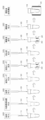
- FIG. 1 is a diagram schematically showing an overall configuration of an automatic analyzer according to a first embodiment of the present invention.
- the automatic analyzer 100 includes a pretreatment unit 101 for pretreating a sample, a separation unit 102 for separating components in a sample, an analysis unit 103 for analyzing the separated components, and an apparatus.
- a control unit 104 for controlling the overall operation, an input unit 105 for the user to input information to the apparatus, a display unit 106 for displaying the information to the user, and various types related to the control of the automatic analyzer 100.
- It is provided with a storage unit 107 such as a storage medium for storing the information of.
- the control unit 104, the input unit 105, the display unit 106, and the storage unit 107 constitute a control device that controls the overall operation of the automatic analyzer 100.
- the input unit 105 and the display unit 106 are shown as separate bodies in the first embodiment, for example, the input unit 105 and the display unit 106 may be integrally configured as in a touch panel type monitor. Good.
- the pretreatment unit 101 has a transfer mechanism 112 for transporting the sample container 111 containing the sample to be analyzed to the sample dispensing position, and the reaction container 116 mounted in the plurality of openings 119 in the reaction container 116.
- a reaction vessel disk 120 capable of holding the solution at a constant temperature, a reagent disk 122 holding a plurality of reagent containers 121 containing reagents, and an opening of the reaction vessel disk 120 from the sample container 111 conveyed to the sample dispensing position.
- a sample dispensing mechanism 113 for dispensing the sample to the reaction vessel 116 housed in the part 119 is provided.
- the pretreatment unit 101 includes a reagent dispensing mechanism 123 for dispensing the reagent from the reagent container 121 to the reaction vessel 116 of the reaction vessel disc 120, and a disposable dispensing chip 115a attached to the nozzle of the sample dispensing mechanism 113.
- the pretreatment unit 101 conveys the reaction vessel mounting rack 117 on which the unused reaction vessel 116 is mounted and the unused dispensing chip 115a from the dispensing chip mounting rack 115 to the dispensing chip attachment / detachment unit 114. Transport of the used reaction vessel 116 from the opening 119 of the reaction vessel disc 120 to the discarding portion (not shown) and the unused reaction vessel from the reaction vessel mounting rack 117 to the opening 119 of the reaction vessel disc 120. A transport mechanism 118 that transports the 116 is provided.
- the pretreatment unit 101 places the reaction vessel 116 between the magnetic separation mechanism 124 that separates the magnetic beads in the solution contained in the reaction vessel 116 by the magnetic force of the magnet, and the reaction vessel disc 120 and the magnetic separation mechanism 124. It is provided with a transport mechanism 125 for transporting and an evaporation concentration mechanism 131 for evaporating and concentrating the components to be analyzed in the solution in the reaction vessel 116.
- the pretreatment section 101 includes a transfer mechanism 132 for transporting the reaction vessel 116 between the reaction vessel disk 120 and the evaporation concentration mechanism 131, and a reaction vessel 116 after evaporation concentration in the separation unit 102 for separating the components in the sample. It is provided with a separation unit dispensing mechanism 133 for dispensing the solution in the solution, and an analysis unit 103 for detecting and analyzing components in the solution separated by the separation unit 102.
- the magnetic separation mechanism 124 is provided on the rotating track 126 of the reagent dispensing mechanism 123.
- the reagent dispensing mechanism 123 can discharge the reagent to the reaction vessel 116 supported by the magnetic separation mechanism 124 and suck the solution in the reaction vessel 116.
- the reaction vessel disk 120 functions as an incubator that keeps the temperature of the reaction vessel 116 installed in the opening 119 constant, and incubates the reaction vessel 116 installed in the opening 119 for a certain period of time.
- the separation unit 102 is, for example, an LC (Liquid Chromatography) and includes a column or the like as a function of separating components in the reaction solution dispensed by the separation unit dispensing mechanism 133.
- the separation unit 102 separates the components in the reaction solution dispensed from the reaction vessel 116 by the separation unit dispensing mechanism 133, and sequentially introduces the separated components into the analysis unit 103.
- the analysis unit 103 is, for example, an MS (Mass Spectrometry: mass spectrometer) and includes an electron multiplier tube or the like as a function of ionizing and mass-analyzing the components introduced from the separation unit 102.
- the analysis unit 103 ionizes the components introduced from the separation unit 102 to detect the amount of ions (that is, the amount of components), and outputs the detection result to the control unit 104.
- the control unit 104 controls the operation of the evaporation concentration mechanism (evaporation concentration unit) 131, the operation of the separation unit 102, and the operation of the analysis unit 103. Further, the control unit 104 calculates the concentration value of the component in the sample using the detection result (ion amount) from the analysis unit 103 and the calibration curve acquired in advance, and stores the analysis result in the storage unit 107. The analysis result is displayed on the display unit 106.
- a calibration curve for example, first, a standard substance having a known concentration is analyzed for a plurality of concentrations. Then, the amount of ions, that is, the time change of ionic strength (mass chromatogram) is obtained with respect to the m / z (mass / charge ratio) of the ions derived from the standard substance, and the peak area of the mass chromatogram is obtained. A calibration curve is created from the relationship between this area and the concentration of the standard substance.
- the peak area of the mass chromatogram is obtained for the sample to be analyzed, and the component concentration of the component to be analyzed is determined from the correspondence between the peak area of this mass chromatogram and the calibration curve.
- the comparison between the data can be performed with high accuracy. That is, it is possible to compare and verify the ionic strength, which may show some fluctuation in each analysis due to the influence of sample pretreatment, sample injection into LC-MS, ionization in LC-MS, etc. .. This method is called the internal standard method.
- FIG. 2 is a diagram showing an example of a pretreatment process of analysis processing by an automatic analyzer.
- an unused reaction vessel 116 is installed from the reaction vessel mounting rack 117 to the opening 119 on the reaction vessel disk 120 by the transport mechanism 118. Further, prior to the dispensing of the sample, the sample dispensing mechanism 113 is made to access the dispensing tip attachment / detachment portion 114, and the dispensing tip 115a is attached to the tip of the nozzle.
- the sample dispensing mechanism 113 sucks the sample containing the analysis target component from the sample container 111 via the dispensing tip 115a and discharges the sample into the reaction vessel 116 of the reaction vessel disc 120 (step S200).
- the used dispensing tip 115a is discarded at the dispensing tip attachment / detachment unit 114, and the unused dispensing tip 115a is discarded.
- the 115a is attached.
- the reagent dispensing mechanism 123 sucks the internal standard substance as the reagent corresponding to the component to be analyzed from the reagent container 121 of the reagent disk 122 and discharges it into the reaction container 116 (step S201).
- the reagent dispensing mechanism 123 sucks, for example, a reagent as a deproteinizing agent from the reagent container 121 of the reagent disk 122, and discharges the reagent into the reaction vessel 116 (step S202).
- the reagent dispensing mechanism 123 sucks the suspension of magnetic beads as a reagent from the reagent container 121 of the reagent disk 122 and discharges it into the reaction container 116 (step S203).
- the reaction vessel 116 into which the sample, the internal standard substance, and the magnetic beads are dispensed is conveyed to the magnetic separation mechanism 124 by the transfer mechanism 125, and the magnetic beads are washed (step S204).
- the magnetic separation mechanism 124 magnetic beads holding the components to be analyzed and the internal standard substance are collected on the inner wall surface of the reaction vessel 116 by the magnetic force of the magnet 201 arranged at a position along the outer surface of the reaction vessel 116 (FIG. In 2, it is shown as a magnetic bead group 202).
- the reagent dispensing mechanism 123 sucks the solution in the reaction vessel 116 and discards it.
- the magnetic beads, the components to be analyzed held by the magnetic beads, and the internal standard substance remain in the reaction vessel 116.
- the reagent dispensing mechanism 123 sucks the cleaning liquid for washing impurities other than the substances (components to be analyzed and internal standard substances) held on the magnetic beads from the reagent container 121 of the reagent disk 122 into the reaction container 116. Discharge.
- the constraint due to the magnetic force of the magnet 201 of the magnetic beads may be temporarily released.
- the reagent dispensing mechanism 123 sucks the solution (cleaning solution) of the reaction vessel 116 and discards it to clean the magnetic beads.
- the reagent dispensing mechanism 123 sucks the eluate that elutes the components to be analyzed and the internal standard substance from the magnetic bead group 202 as a reagent from the reagent container 121 of the reagent disk 122 and discharges it into the reaction vessel 116 (step). S205).
- Step S206 the solution (purified solution) of the reaction vessel 116 (purified liquid) was collected by the reagent dispensing mechanism 123 on the inner wall surface of the reaction vessel 116 by the magnetic force of the magnet 201. ) (Step S206) and is discharged into an unused reaction vessel 116 of the reaction vessel disc 120 different from the reaction vessel 116 arranged in the magnetic separation mechanism 124 (step S207).
- the purified liquid contained in the reaction vessel 116 of the reaction vessel disc 120 is incubated.
- reaction vessel 116 containing the purified liquid is transported to the evaporation concentration mechanism 131 by the transport mechanism 132, and the components in the purified liquid are evaporated and concentrated (step S208).
- the detailed configuration of the evaporation concentration mechanism 131 will be described later.
- the reagent dispensing mechanism 123 is used to dilute the diluted liquid from the reagent container 121 of the reagent disk 122. Is sucked and discharged into the reaction vessel 116.
- the purified liquid obtained by the above pretreatment step is sucked from the reaction vessel 116 by the dispensing mechanism 133 for the separation unit and discharged to the separation unit 102, and the components separated by the separation unit 102 are ionized by the analysis unit 103.
- the amount of ions (that is, the amount of components) is detected.
- the detection result of the analysis unit 103 is output to the control unit 104, and the concentration value of the component in the sample is calculated using the calibration curve.
- the automatic analyzer has an evaporation concentration mechanism and a control method that can select whether or not to carry out evaporation concentration for each component to be analyzed, that is, for each sample. For example, each sample is assigned an identification number, and which identification number the sample is subjected to the evaporation concentration treatment is stored in the storage unit 107 via the input unit 105, and is based on the content stored in the control unit 104. Then, the presence or absence of evaporation concentration is selected for each sample, and the sample processing is executed.
- control unit 104 determines whether or not the component to be analyzed in the sample is subjected to the evaporation concentration treatment, and the sample determined to be subjected to the evaporation concentration treatment is subjected to the evaporation concentration mechanism (evaporation concentration unit) 131. Concentrate the components to be analyzed in the sample.
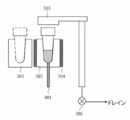
- FIG. 3 is a diagram schematically showing an example of the evaporation concentration mechanism 131 according to the first embodiment of the present invention.
- the evaporation concentration mechanism 131 has a plurality of container receiving portions 301 for receiving the reaction vessel 116 containing the purified liquid obtained by the above-mentioned pretreatment step, and the reaction vessel is conveyed to the container receiving portion 301.
- Each 116 is distributed to either the container receiving unit 301 of the evaporation concentration unit 302 that performs evaporation concentration or the container receiving unit 301 of the standby unit 303 that does not perform evaporation concentration.
- the evaporation concentration mechanism 131 includes a heating means 304 for heating the reaction vessel 116 and an exhaust means 305 for sucking the vapor in the reaction vessel 116.
- the heating means 304 include a Peltier element and a heater whose temperature can be controlled by an analyzer.
- An example of the exhaust means 305 is a vacuum pump or the like whose operation can be controlled by an analyzer. Further, a valve 306 may be provided between the opening of the exhaust means 305 and the drain.
- the first example is a method of moving the evaporation concentration mechanism 131.
- the control unit 104 moves the evaporation / concentration mechanism 131 so that the point at which the transfer mechanism 132 accesses the evaporation / concentration mechanism 131 coincides with the container receiving unit 301.
- the reaction vessel 116 is transported to the container receiving unit 301 on the standby unit 303 by the transport mechanism 132, and after waiting for a certain period of time, the purified liquid is used. Is introduced into the separation unit 102 by the dispensing mechanism 133 for the separation unit.
- the reaction vessel 116 is conveyed to the container receiving portion 301 on the evaporation concentration unit 302 by the transfer mechanism 132.
- the exhaust means 305 is arranged at a position (first position) near the heating unit 304 of the evaporation concentration unit 302 and separated from the heating unit 304 by a certain distance or more.
- the exhaust means exhaust unit
- the exhaust means is located above the reaction vessel 116 arranged in the heating unit 304 so as to be arranged at a position close to the reaction vessel 116 (position close to the heating unit 304: second position).
- Move 305 In this case, the evaporation concentration mechanism 131 may be moved.
- the reaction vessel 116 is evaporated and concentrated by exhausting the reaction vessel 116 in a state of being heated by the heating means (heating unit) 304 and in a state where the valve 306 is opened for a certain period of time.
- the evaporation concentration unit 302 is raised with respect to the exhaust means 305, or the exhaust means 305 is lowered with respect to the reaction vessel 116, so that the opening of the reaction vessel 116 is brought into close contact with the exhaust means 305. And better.
- reaction vessel 116 and the vessel receiving portion 301 are in close contact with each other, so that the reaction vessel 116 cannot be removed when the reaction vessel 116 is carried out from the container receiving portion 301.
- an ejector pin 401 for pushing up the reaction vessel 116 from below may be provided. By making the ejector pin 401 a mechanism that moves up and down at the same time as the exhaust means 305, it is possible to reduce the number of drive means such as a motor.
- the second example is a method of fixing the installation position of the evaporation concentration mechanism 131.
- the control unit 104 conveys the reaction vessel 116 to the container receiving unit 301 of the evaporation concentration unit 302 or the standby unit 303 by the transfer mechanism 132, depending on whether or not the sample is subjected to evaporation concentration.
- the exhaust means 305 is moved with respect to the reaction vessel 116 on the evaporation concentration unit 302 so that the exhaust means 305 is located above the reaction vessel 116.
- reaction vessel 116 is heated and exhausted for a certain period of time to evaporate and concentrate. Then, the purified liquid in the reaction vessel 116 is introduced into the separation unit 102 by the separation unit dispensing mechanism 133 that can access the container receiving unit 301 of the evaporation concentration mechanism 131.
- the number of container receiving units 301 in FIG. 3 is an example, and should be changed in consideration of the number of samples that can be processed per hour set in the automatic analyzer, that is, the throughput, the time required for evaporation concentration, and the like. Can be done. Assuming that the throughput is 100 samples / hour (36 seconds / sample) and the time required for evaporation concentration is 108 seconds (36 seconds x 3), the evaporation concentration unit 302 and the standby unit 303 each have three container receiving units. If 301 is provided, the evaporation concentration mechanism 131 can sequentially process the reaction vessel 116 without any free time even when the same treatment is continuously carried out, and a throughput of 100 samples / hour can be obtained. At this time, the exhaust means 305 is required for each of the three container receiving portions 301 in the evaporation concentrating portion 302.
- valve 306 When the reaction vessel 116 and the exhaust means 305 are brought into close contact with each other to perform exhaust, the valve 306 is opened during suction of steam and the valve 306 is closed after the suction is completed so that the reaction vessel 116 does not separate from the exhaust means 116. You can prevent that.
- heating the exhaust means 305 itself can be mentioned.
- air suction by the exhaust means 305 can be performed as a countermeasure.
- the sample requiring the evaporation concentration treatment is moved to the evaporation concentration unit 302, and the sample not requiring the evaporation concentration treatment is a standby unit not subjected to the evaporation concentration treatment.
- the sample that is moved to 303 and needs the evaporation concentration treatment is subjected to the evaporation concentration treatment in the evaporation concentration unit 302, and is moved to the separation unit 102 together with the sample that does not need the evaporation concentration treatment. Then, in the separation unit 102, the separated components are moved to the analysis unit 103, and analysis is performed.
- an automatic analyzer capable of controlling the evaporation concentration of the sample by selecting whether or not the evaporation concentration is performed for each sample.
- the standby unit 303 and the evaporation concentration unit 302 are adjacent to each other, but the standby unit 303 is formed of a heat insulating material and is affected by the heat from the evaporation concentration unit 302.
- the configuration can be restricted.
- the standby unit 303 and the evaporation concentration unit 302 can be arranged apart from each other so as not to be affected by heat.
- Example 2 Next, Example 2 of the present invention will be described.
- Example 2 the configuration of the evaporation concentration mechanism is different from that of Example 1, and the other configurations are the same. For this reason, illustration and detailed description of parts other than the evaporation concentration mechanism will be omitted.
- FIG. 5 is a diagram schematically showing the evaporation concentration mechanism 131 in Example 2.
- the evaporation concentration mechanism 131 has a container support portion 501 that receives and supports the reaction vessel 116 containing the purified liquid obtained by the above-mentioned pretreatment step, and the reaction vessel is conveyed to the container support portion 501. For each 116, the presence or absence of evaporation concentration is controlled.
- the evaporative concentration mechanism 131 in the second embodiment includes a heating means 502 for heating the reaction vessel 116 and a movable means (movable portion) 503 that controls contact / non-contact of the heating means 502 with the reaction vessel 116.
- the exhaust means 305 for sucking the vapor in the reaction vessel 116 and the valve 306 between the opening and the drain of the exhaust means 305 are provided.
- the reaction vessel 116 is transported to the container support portion 501 of the evaporation concentration mechanism 131 by the transport mechanism 132.
- the heating means (heating unit) 502 is located in a non-heating position where it does not come into contact with the reaction vessel 116 and does not heat the extract in the reaction vessel 116 when evaporation concentration is not performed.
- the heating means 502 is moved by the movable means (movable part) 503 in a direction approaching the reaction vessel 116 and moved to a position (heating position) in contact with the reaction vessel 116. , The extract in the reaction vessel 116 is heated.
- the exhaust means 305 is moved to the upper part of the reaction vessel 116 to perform heating and exhaust with the valve 306 open for a certain period of time.
- the movable means 503 When the purified liquid in the reaction vessel 116 is not subjected to evaporation concentration, the movable means 503 maintains a state in which the heating means 502 is separated from the reaction vessel 116 by a certain interval or more, and the reaction vessel 116 and the heating means are separated. A state in which the 502 does not come into contact with each other is maintained for a certain period of time.
- the purified liquid in the reaction vessel 116 is introduced into the separation section 102 by the separation section dispensing mechanism 133.
- Example 1 by moving the heating means 502 without providing a standby unit separately from the evaporation unit, contact and non-contact with the reaction vessel 116 are performed, and evaporation concentration is performed. It is possible to sort out whether or not the above is carried out for each reaction vessel 116.
- the same effect as that of the first embodiment can be obtained, and the contact between the heating means 502 and the reaction vessel 16 can be opened by the movable means 503, which is shown in FIG. There is no need to consider arranging such ejector pins.
- the evaporation concentration mechanism 131 can be miniaturized.
- Example 3 of the present invention field will be described.
- Example 3 the configuration of the evaporation concentration mechanism is different from that of Example 1, and the other configurations are the same. For this reason, illustration and detailed description of parts other than the evaporation concentration mechanism will be omitted.
- Example 3 by installing the evaporation concentration unit 302 in one area provided with the exhaust means, it is possible to carry out evaporation concentration at one time for a plurality of reaction vessels 116.
- FIG. 6 is a diagram showing the third embodiment, and is a diagram schematically showing an example in which the evaporation concentration unit 302 is installed in one area provided with an exhaust means. Further, FIG. 7 is a diagram showing a modified example of the example shown in FIG.
- the exhaust means (exhaust unit) 604 exhausts the inside of the evaporation concentration area 601.
- Examples of the opening / closing means 602 and 603 include shutters whose opening / closing can be controlled by an automatic analyzer.
- An example of the exhaust means 604 is a vacuum pump or the like whose operation can be controlled by an automatic analyzer.
- FIG. 6 shows a method of moving the evaporation concentration unit 302.
- the evaporation concentration unit is located at a point where the transport mechanism 132 can access the container receiving unit 301 in order to receive the reaction vessel 116 for performing evaporation concentration. Move 302.
- reaction vessel 116 is carried into the vessel receiving unit 301 by the transport mechanism 132. If the reaction vessel 116 is continuously carried into the plurality of vessel receiving portions 301, the above operation is repeated.
- the opening / closing means 602 is closed, the evaporation concentration area 601 is closed from the outside air, and the exhaust means 604 is operated.
- the opening / closing means 603 is opened, and the transfer mechanism 132 moves the evaporation concentration unit 302 to a point where the dispensing mechanism 133 for the separation unit can access the reaction vessel 116. After that, the purified liquid in the reaction vessel 116 is introduced into the separation unit 102 by the dispensing mechanism 133 for the separation unit.
- the example shown in FIG. 7 is an example of a method of fixing the installation position of the evaporation concentration unit 302.
- the reaction vessel 116 for performing evaporation concentration is carried into the container receiving portion 301 of the evaporation concentration unit 302 by the transport mechanism 132. If the reaction vessel 116 is continuously carried into the plurality of vessel receiving portions 301, the above operation is repeated.
- the exhaust means 604 is operated. After the evaporative concentration is carried out for a certain period of time, the opening / closing means 603 is opened, and the purified liquid in the reaction vessel 116 is introduced into the separation unit 102 by the dispensing mechanism 133 for the separation unit.
- the same effect as that of the first embodiment can be obtained, and only one exhaust means 604 can be used.
- Example 4 of the present invention will be described.
- the concentration ratio calculation process of Example 4 is a process of calculating the concentration rate of the sample subjected to the evaporation concentration treatment or determining the presence or absence of an abnormality in the evaporation concentration treatment.
- the determination process of the fourth embodiment can be applied to any of the first to third embodiments.
- Example 4 is an example for confirming whether or not the concentration treatment has been performed reliably, determining the case where the concentration is abnormal, and ensuring reliability.
- FIG. 8 is a diagram showing an example of a step of calculating the concentration ratio of the purified liquid obtained by the pretreatment step.
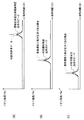
- FIGS. 9 to 11 are diagrams schematically showing an example of a mass chromatogram acquired by the analysis unit for each of the standard substance for calculating the concentration ratio, the internal standard substance, the standard substance, and the component to be analyzed. The vertical axis shows the ionic strength, and the horizontal axis shows the LC retention time.
- FIG. 9A is a mass chromatogram derived from a standard substance for calculating the concentration ratio
- FIG. 9B is a mass chromatogram derived from an internal standard substance
- FIG. 9C is a mass chromatogram. The mass chromatogram derived from the standard substance is shown.
- FIGS. 10 and 11 are a standard substance for calculating the concentration ratio
- (B) is an internal standard substance
- (C) is a mass chromatogram derived from each of the components to be analyzed. It is explanatory drawing about the comparative example of.
- reaction vessel 116 containing the purified liquid obtained by the above-mentioned pretreatment step is conveyed to the evaporation concentration mechanism 131, and the analysis target component 801 in the purification liquid is evaporated and concentrated (step S208).
- the diluent is sucked from the reagent container 121 of the reagent disk 122 by the reagent dispensing mechanism 123. Discharge to the reaction vessel 116 (step S801).
- a predetermined standard substance 802 for calculating the concentration ratio is added to the reagent container 121 containing the diluent according to Example 4.
- a substance that is detected at the same time as the analysis target component is selected within the LC retention time range in which the analysis target component of the sample to be analyzed is detected.
- a standard substance having a known concentration is analyzed according to the process of analysis processing, a mass chromatogram of the standard substance (see FIG. 9 and the like) is acquired in advance, and recorded in the storage unit 107 as reference data for determination.
- data including peaks derived from the components to be analyzed and the internal standard substance of the sample can be obtained, and the same LC can be obtained.
- Data including peaks derived from the reference material for calculating the concentration ratio can be obtained within the retention time range of (see FIGS. 10 and 11).
- Data standardization is, for example, comparing peaks at the same holding time and calculating what percentage of the peak area of the acquired data is when the size of the peak area of the judgment reference data is 100%. It is done by.
- the difference ratio represented by the following equation (1) is defined as an index indicating the degree of discrepancy between the determination reference data and the acquired data.
- Difference ratio (%) ⁇ 1- (acquired data) / (judgment reference data) ⁇ ⁇ 100 ⁇ ⁇ ⁇ (1)
- the difference ratio given by the above formula (1) is compared with a preset difference ratio threshold value, and the presence or absence of an abnormality in evaporation concentration is determined based on the comparison result. That is, the presence or absence of an abnormality in evaporation concentration can be temporarily determined by calculating the difference ratio at the same time as calculating the concentration of the component to be analyzed and comparing it with the difference ratio threshold value.
- the determination process is executed by the control unit 104.
- the difference ratio threshold value as a judgment standard is set in advance prior to the analysis process and the evaporation concentration abnormality judgment process, and is stored in the storage unit 107 in the same manner as the judgment reference data. It should be noted that the operator may be able to input as appropriate. It is known that the standard measurement error of LC-MS is about 5 to 10%. Therefore, in the fourth embodiment, the case where the difference ratio threshold value is set to 15% will be described as an example.
- the difference ratio threshold value may be set for each device so as to further improve the determination accuracy of the abnormality of evaporation concentration.
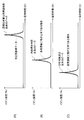
- the peak area derived from the concentration ratio calculation standard substance is compared. Is less in the data acquired during sample analysis than in the criterion data for judgment.
- this difference ratio exceeds the difference ratio threshold value (15%), it is determined that there is an abnormality in which the amount of evaporation of the purified liquid is reduced in the evaporation concentration treatment. This is because when the amount of evaporation is small, the total amount of the purified liquid after adding the diluent containing the standard substance for calculating the concentration ratio is larger than that in the normal state, and the concentration of the standard substance for calculating the concentration ratio is low.
- FIG. 10 (B) the concentrations of the components to be analyzed and the internal standard substance in the purified liquid decrease and the peak area decreases, so that as shown in FIG. 10 (C). The concentration of the component to be analyzed is calculated to be small.
- the data derived from the component to be analyzed is standardized by the data derived from the internal standard substance, or the data derived from the component to be analyzed is standardized by the data derived from the standard substance for calculating the concentration ratio by the internal standard method. It may be corrected by.
- the peak area derived from the standard substance for calculating the concentration ratio is compared. Is more in the data acquired during sample analysis than in the criterion data for judgment.
- this difference ratio exceeds the difference ratio threshold value (15%), it is determined that there is an abnormality in which the amount of evaporation of the purified liquid increases in the evaporation concentration treatment.
- the amount of evaporation increases, as shown in FIG. 11B, the total amount of the purified liquid after adding the diluent containing the reference substance for calculating the concentration ratio becomes smaller than in the normal state, and for calculating the concentration ratio. This is because the concentration of the standard substance is high.
- the concentrations of the components to be analyzed and the internal standard substance in the purified liquid increase and the peak area increases, the concentrations of the components to be analyzed are calculated in large amounts as shown in FIG. 11 (C). It ends up.
- the data derived from the component to be analyzed is standardized by the data derived from the internal standard substance, or the data derived from the component to be analyzed is standardized by the data derived from the standard substance for calculating the concentration ratio by the internal standard method. It may be corrected by.
- the control unit 104 determines whether or not the evaporation concentration process is sufficient, and if it determines that the evaporation concentration process is insufficient, the control unit 104 causes the display unit 106 to display an alarm indicating that the evaporation concentration process is insufficient. Is possible.
- MS isotope-labeled stable isotope compounds of the components to be analyzed or compounds with similar chemical and physical properties (similar compounds) as internal standard substances.
- the standard substance for calculating the concentration ratio it can be captured by magnetic beads during the pretreatment of the sample, and it is derived from the component to be analyzed and the internal standard substance in the mass chromatogram. A substance that is sufficiently separated from the peak and is detected within the LC retention time measured for the component to be analyzed is selected as the standard substance for calculating the concentration ratio.
- Example 4 the component to be analyzed is captured by the hydrophobic interaction with the magnetic beads. Also, in LC, a reverse phase column is usually used as the separation column. Retention on a reversed-phase column is basically based on hydrophobic interactions.
- the standard substance for calculating the concentration ratio has hydrophobicity that is captured by magnetic beads and a reverse phase column to the same extent as the component to be analyzed.
- a non-dissociated ionic compound is generally highly hydrophobic, so that it can be retained in a reverse phase column.
- the difference between the dissociated state and the non-dissociated state arises from the relationship between the pH of the mobile phase of LC and the pKa of the compound.
- the retention behavior can be stabilized by setting the pKa of the component to be analyzed and the internal standard substance to a value that is ⁇ 2 or more away from the pH of the mobile phase. That is, in consideration of the above, from the balance between the pKa of the analysis target component or the internal standard substance and the mobile phase, the peaks derived from the analysis target component or the internal standard substance are sufficiently separated from the chromatogram, and the analysis target component is sufficiently separated. It is important to select a substance that can be detected within the holding time of LC to be measured as a standard substance for calculating the concentration ratio.
- the peak m / z of the mass chromatogram derived from the component to be analyzed, the internal standard substance, and the standard substance for calculating the concentration ratio is at least 1 [Da]. It is desirable that the distance is preferably 3 [Da] or more.
- the MS used as a detector uses an apparatus equipped with an MS / MS method capable of detecting product ions. Is desirable.
- the MS / MS method is used, even if the m / z of the precursor ions of each substance is the same, the m / z of the product ions may be different.
- Example 4 of the present invention a diluted solution containing a standard substance was added to the extract that had been concentrated by the evaporation concentration unit 131, and the analysis unit 103 detected and detected the signal amount of the standard substance. Since the concentration ratio of the extract is calculated from the signal amount, the sample to be heated and the sample not to be heated are mixed, and the sample to be heated is concentrated and continuously in a constant cycle. In the case of specific treatment, reliability can be ensured because it is configured to confirm whether or not the concentration treatment has been reliably performed and to determine if the concentration is abnormal.
- the present invention configured as described above has the following effects.
- the extract from which the components to be analyzed are extracted is evaporated to prepare the sample solution.
- the mechanism 131 is provided.
- the evaporative concentration mechanism 131 has a container receiving unit 301 that receives the reaction container 116 containing the extract, and a mechanism and control for allocating whether or not to perform evaporation concentration for each reaction container 116 that reaches the container receiving unit 301. Since the method is provided, it is possible to select whether or not to carry out evaporation concentration for each sample, and it is possible to realize an automatic analyzer capable of controlling evaporation concentration of the sample.
- each of the above configurations, functions, etc. may be realized by designing a part or all of them by, for example, an integrated circuit. Further, each of the above configurations, functions, and the like may be realized by software by the processor interpreting and executing a program that realizes each function.
- the analysis unit 103 may be an optical analyzer other than the mass spectrometer, for example.
- 100 Automatic analyzer, 101 ... Preprocessing unit, 102 ... Separation unit, 103 ... Analysis unit, 104 ... Control unit, 105 ... Input unit, 106 ... Display unit , 107 ... Storage unit, 111 ... Sample container, 112 ... Conveyance mechanism, 113 ... Sample dispensing mechanism, 114 ... Dispensing chip attachment / detachment unit, 115 ... Dispensing chip mounted Rack, 115a ... Dispensing chip, 116 ... Reaction vessel, 117 ... Reaction vessel mounting rack, 118 ... Conveyance mechanism, 119 ... Opening, 120 ... Reaction vessel disc, 121. .. Reagent container, 122 ... Reagent disk, 123 ...
- Reagent dispensing mechanism 124 ... Magnetic separation mechanism, 125 ... Conveyance mechanism, 126 ... Rotational orbit, 131 ... Evaporation concentration mechanism , 132 ... Conveying mechanism, 133 ... Dispensing mechanism for separation part, 201 ... Magnet, 202 ... Magnetic bead group, 203 ... Magnetic bead group, 301 ... Container receiving part, 302 ... Evaporation and concentration section, 303 ... Standby section, 304 ... Heating means, 305 ... Exhaust means, 306 ... Valve, 401 ... Ejector pin, 501 ... Container support section, 502 ... Heating means, 503 ... Movable means, 601 ... Evaporation concentration area, 602 ... Opening and closing means, 603 ... Opening and closing means, 604 ... Exhaust means, 801 ... Components to be analyzed, 802: Standard substance for calculating concentration ratio
Landscapes
- Chemical & Material Sciences (AREA)
- Health & Medical Sciences (AREA)
- Immunology (AREA)
- Analytical Chemistry (AREA)
- Physics & Mathematics (AREA)
- Biochemistry (AREA)
- General Health & Medical Sciences (AREA)
- General Physics & Mathematics (AREA)
- Life Sciences & Earth Sciences (AREA)
- Pathology (AREA)
- Engineering & Computer Science (AREA)
- Quality & Reliability (AREA)
- Chemical Kinetics & Catalysis (AREA)
- Sampling And Sample Adjustment (AREA)
- Other Investigation Or Analysis Of Materials By Electrical Means (AREA)
- Automatic Analysis And Handling Materials Therefor (AREA)
Abstract
Description
図1は、本発明の実施例1に係る自動分析装置の全体構成を概略的に示す図である。
次に、本発明の実施例2について説明する。
次に、本発明野実施例3について説明する。
次に、本発明の実施例4について説明する。
差分比率(%)=│1-(取得したデータ)/(判定用基準データ)│×100 ・・・(1)
Claims (10)
- 試料中の分析対象成分を抽出した抽出液を蒸発させて前記分析対象成分を濃縮する濃縮処理を行う蒸発濃縮部と、
前記試料の分析対象成分を分析する分析部と、
前記蒸発濃縮部及び前記分析部の動作を制御する制御部と、
を備える自動分析装置において、
前記制御部は、前記試料中の分析対象成分に対して蒸発濃縮処理を行うか否かを判定し、蒸発濃縮処理を行うと判定した試料に対して前記蒸発濃縮部により前記試料中の分析対象成分を濃縮させることを特徴とする自動分析装置。 - 請求項1に記載の自動分析装置において、
前記蒸発濃縮部は、前記抽出液を加熱して蒸発させる加熱部と、
前記加熱部により発生した蒸気を吸引する排気部と、を有することを特徴とする自動分析装置。 - 請求項2に記載の自動分析装置において、
前記蒸発濃縮部は、前記制御部が、蒸発濃縮を行わない判定した試料を待機させる待機部を、さらに有することを特徴とする自動分析装置。 - 請求項2に記載の自動分析装置において、
前記排気部は、前記加熱部と一定距離離間した第1の位置と、前記加熱部と密接する第2の位置との間を移動し、
前記制御部は、
前記蒸発濃縮を行わない際には、前記第1の位置に前記排気部を配置し、
前記蒸発濃縮を行う際には、前記第2の位置まで前記排気部を移動させることを特徴とする自動分析装置。 - 請求項2に記載の自動分析装置において、
前記抽出液は、容器に収容され、
前記加熱部は、前記容器を受容する容器受容部と、前記容器受容部に収容された前記容器を下方から押し上げるエジェクタピンを有することを特徴とする自動分析装置。 - 請求項2に記載の自動分析装置において、
前記抽出液は、容器に収容され、
前記加熱部を、前記容器と接触せず、前記容器内の抽出液を加熱しない非加熱位置と、前記容器に接触させる加熱位置との間を移動させる可動部を備えることを特徴とする自動分析装置。 - 請求項2に記載の自動分析装置において、
前記加熱部は、蒸発濃縮エリア内に配置され、前記蒸発濃縮エリアを開閉する開閉部を備え、前記排気部は、前記蒸発濃縮エリア内を排気することを特徴とする自動分析装置。 - 請求項2に記載の自動分析装置において、
前記蒸発濃縮部により前記濃縮処理が行われた前記抽出液に標準物質を含む希釈液を添加し、前記分析部により、前記標準物質の信号量を検出し、検出した前記信号量から、前記抽出液の濃縮比率を算出することを特徴とする自動分析装置。 - 請求項8に記載の自動分析装置において、
表示部を備え、前記制御部は、前記抽出液の濃縮比率から蒸発濃縮処理が十分か否かを判定し、不十分であると判定すると、蒸発濃縮処理が不十分であることを示すアラームを前記表示部に表示させるこことを特徴とする自動分析装置。 - 請求項2に記載の自動分析装置において、
蒸発濃縮処理対象の試料と、蒸発濃縮処理を行わない試料とを混在して一定間隔で連続的に処理することを特徴とする自動分析装置。
Priority Applications (4)
| Application Number | Priority Date | Filing Date | Title |
|---|---|---|---|
| JP2021529185A JP7402875B2 (ja) | 2019-07-04 | 2020-07-02 | 自動分析装置 |
| CN202080047940.XA CN114072679B (zh) | 2019-07-04 | 2020-07-02 | 自动分析装置 |
| EP20834676.7A EP3995832A4 (en) | 2019-07-04 | 2020-07-02 | AUTOMATIC ANALYSIS DEVICE |
| US17/622,908 US12529709B2 (en) | 2019-07-04 | 2020-07-02 | Automatic analysis device |
Applications Claiming Priority (2)
| Application Number | Priority Date | Filing Date | Title |
|---|---|---|---|
| JP2019-125016 | 2019-07-04 | ||
| JP2019125016 | 2019-07-04 |
Publications (1)
| Publication Number | Publication Date |
|---|---|
| WO2021002431A1 true WO2021002431A1 (ja) | 2021-01-07 |
Family
ID=74100386
Family Applications (1)
| Application Number | Title | Priority Date | Filing Date |
|---|---|---|---|
| PCT/JP2020/026012 Ceased WO2021002431A1 (ja) | 2019-07-04 | 2020-07-02 | 自動分析装置 |
Country Status (5)
| Country | Link |
|---|---|
| US (1) | US12529709B2 (ja) |
| EP (1) | EP3995832A4 (ja) |
| JP (1) | JP7402875B2 (ja) |
| CN (1) | CN114072679B (ja) |
| WO (1) | WO2021002431A1 (ja) |
Cited By (7)
| Publication number | Priority date | Publication date | Assignee | Title |
|---|---|---|---|---|
| WO2022230282A1 (ja) * | 2021-04-27 | 2022-11-03 | 株式会社日立ハイテク | 自動分析装置 |
| WO2023074351A1 (ja) * | 2021-10-25 | 2023-05-04 | 株式会社日立ハイテク | 自動分析装置の制御方法、自動分析装置 |
| WO2023095560A1 (ja) * | 2021-11-24 | 2023-06-01 | 株式会社日立ハイテク | 自動分析装置 |
| CN116868042A (zh) * | 2021-03-03 | 2023-10-10 | 株式会社日立高新技术 | 蒸发浓缩机构以及蒸发浓缩机构的控制方法 |
| WO2024214544A1 (ja) * | 2023-04-10 | 2024-10-17 | 株式会社日立ハイテク | 蒸発濃縮機構及びそれを備える自動分析装置 |
| WO2025243688A1 (ja) * | 2024-05-20 | 2025-11-27 | 株式会社日立ハイテク | 処理装置 |
| WO2025263417A1 (ja) * | 2024-06-21 | 2025-12-26 | 株式会社日立ハイテク | 処理装置及び自動分析装置 |
Families Citing this family (2)
| Publication number | Priority date | Publication date | Assignee | Title |
|---|---|---|---|---|
| ES3006019T3 (en) * | 2020-12-17 | 2025-03-17 | Hoffmann La Roche | Evaporation-based sample preparation workflow for mass spectrometry |
| CN116139534A (zh) * | 2023-01-14 | 2023-05-23 | 广东青云山药业有限公司 | 用于丹参提取的自动逆流提取装置的控制方法及系统 |
Citations (6)
| Publication number | Priority date | Publication date | Assignee | Title |
|---|---|---|---|---|
| JPH10260118A (ja) * | 1997-03-19 | 1998-09-29 | Dainippon Seiki:Kk | 液体試料中の成分物質の自動抽出装置および液体試料中の成分物質の自動濃度測定装置 |
| JP2009042117A (ja) * | 2007-08-09 | 2009-02-26 | Olympus Corp | 恒温槽および自動分析装置 |
| JP2013174488A (ja) * | 2012-02-24 | 2013-09-05 | Panasonic Corp | 揮発性物質濃縮方法 |
| US20160346712A1 (en) * | 2016-08-09 | 2016-12-01 | Parto Negar Persia Co. | Automated solid phase extraction |
| JP2018205046A (ja) * | 2017-05-31 | 2018-12-27 | シスメックス株式会社 | 試料調製装置、試料調製システム、試料調製方法及び粒子分析装置 |
| JP2019505773A (ja) * | 2015-12-18 | 2019-02-28 | エフ ホフマン−ラ ロッシュ アクチェン ゲゼルシャフト | 自動化された臨床診断システムおよび方法 |
Family Cites Families (14)
| Publication number | Priority date | Publication date | Assignee | Title |
|---|---|---|---|---|
| JP3673789B2 (ja) * | 2003-03-31 | 2005-07-20 | 株式会社日立製作所 | 気化ガス検出方法および気化ガス検出装置 |
| DE102010022016A1 (de) | 2010-05-29 | 2011-12-01 | Gerstel Systemtechnik Gmbh & Co.Kg | Vorrichtung zur Durchführung einer Probenvorbereitung |
| CN103282770B (zh) * | 2011-01-07 | 2015-08-12 | 株式会社日立高新技术 | 质量分析装置、分析法和校准试样 |
| JP5862668B2 (ja) * | 2011-07-26 | 2016-02-16 | 株式会社島津製作所 | ガス吹付式蒸発・乾固装置 |
| JP5882043B2 (ja) * | 2011-12-20 | 2016-03-09 | 株式会社アルバック | 検量線作成装置、検量線作成方法、及びプログラム、並びに濃度定量装置及び濃度定量方法。 |
| JP5924950B2 (ja) * | 2012-01-20 | 2016-05-25 | シスメックス株式会社 | 試料分析装置 |
| US10379132B1 (en) * | 2015-02-02 | 2019-08-13 | Elemental Scientific, Inc. | Auto-sampling system with inline preparation of concentrated sulfuric acid and phosphoric acid for analytic elemental determination |
| CN105717227B (zh) * | 2016-02-02 | 2017-08-04 | 天津科技大学 | 一种浓缩苹果汁风味品质判别方法及其应用 |
| EP3427031B1 (en) * | 2016-03-07 | 2025-12-17 | Yokogawa Fluence Analytics, Inc. | Device and methods for simultaneous determination of intrinsic viscosity and non-newtonian behavior of polymers |
| US10809259B2 (en) * | 2016-10-21 | 2020-10-20 | The University Of Toledo | Protocol for preconcentration and quantification of microcystins using LC-MS |
| US10436794B1 (en) * | 2016-10-21 | 2019-10-08 | The University Of Toledo | Protocol for preconcentration and quantification of microcystins using LC-MS |
| CN107102079A (zh) * | 2017-04-26 | 2017-08-29 | 苏州海科医药技术有限公司 | 检测人血浆中阿托伐他汀及代谢物的液相色谱‑串联质谱方法及临床药动学研究的应用 |
| US11162879B2 (en) * | 2017-07-24 | 2021-11-02 | Kanomax Fmt, Inc. | Particle detection system and method |
| US20240019347A1 (en) * | 2020-12-07 | 2024-01-18 | Hitachi High-Tech Corporation | Evaporative concentration mechanism, analyzer including the same, and method of controlling evaporative concentration mechanism |
-
2020
- 2020-07-02 US US17/622,908 patent/US12529709B2/en active Active
- 2020-07-02 EP EP20834676.7A patent/EP3995832A4/en active Pending
- 2020-07-02 CN CN202080047940.XA patent/CN114072679B/zh active Active
- 2020-07-02 WO PCT/JP2020/026012 patent/WO2021002431A1/ja not_active Ceased
- 2020-07-02 JP JP2021529185A patent/JP7402875B2/ja active Active
Patent Citations (6)
| Publication number | Priority date | Publication date | Assignee | Title |
|---|---|---|---|---|
| JPH10260118A (ja) * | 1997-03-19 | 1998-09-29 | Dainippon Seiki:Kk | 液体試料中の成分物質の自動抽出装置および液体試料中の成分物質の自動濃度測定装置 |
| JP2009042117A (ja) * | 2007-08-09 | 2009-02-26 | Olympus Corp | 恒温槽および自動分析装置 |
| JP2013174488A (ja) * | 2012-02-24 | 2013-09-05 | Panasonic Corp | 揮発性物質濃縮方法 |
| JP2019505773A (ja) * | 2015-12-18 | 2019-02-28 | エフ ホフマン−ラ ロッシュ アクチェン ゲゼルシャフト | 自動化された臨床診断システムおよび方法 |
| US20160346712A1 (en) * | 2016-08-09 | 2016-12-01 | Parto Negar Persia Co. | Automated solid phase extraction |
| JP2018205046A (ja) * | 2017-05-31 | 2018-12-27 | シスメックス株式会社 | 試料調製装置、試料調製システム、試料調製方法及び粒子分析装置 |
Non-Patent Citations (1)
| Title |
|---|
| See also references of EP3995832A4 * |
Cited By (16)
| Publication number | Priority date | Publication date | Assignee | Title |
|---|---|---|---|---|
| US12502623B2 (en) | 2021-03-03 | 2025-12-23 | Hitachi High-Tech Corporation | Evaporation concentration mechanism and method for controlling same |
| CN116868042A (zh) * | 2021-03-03 | 2023-10-10 | 株式会社日立高新技术 | 蒸发浓缩机构以及蒸发浓缩机构的控制方法 |
| EP4303587A4 (en) * | 2021-03-03 | 2025-01-08 | Hitachi High-Tech Corporation | EVAPORATIVE CONCENTRATION MECHANISM AND METHOD FOR CONTROLLING THE EVAPORATIVE CONCENTRATION MECHANISM |
| JPWO2022230282A1 (ja) * | 2021-04-27 | 2022-11-03 | ||
| WO2022230282A1 (ja) * | 2021-04-27 | 2022-11-03 | 株式会社日立ハイテク | 自動分析装置 |
| JP7688149B2 (ja) | 2021-10-25 | 2025-06-03 | 株式会社日立ハイテク | 自動分析装置の制御方法、自動分析装置 |
| WO2023074351A1 (ja) * | 2021-10-25 | 2023-05-04 | 株式会社日立ハイテク | 自動分析装置の制御方法、自動分析装置 |
| JPWO2023074351A1 (ja) * | 2021-10-25 | 2023-05-04 | ||
| EP4425184A4 (en) * | 2021-10-25 | 2025-10-29 | Hitachi High Tech Corp | METHOD FOR CONTROLLING AN AUTOMATIC ANALYSIS DEVICE AND AN AUTOMATIC ANALYSIS DEVICE |
| WO2023095560A1 (ja) * | 2021-11-24 | 2023-06-01 | 株式会社日立ハイテク | 自動分析装置 |
| JP7644262B2 (ja) | 2021-11-24 | 2025-03-11 | 株式会社日立ハイテク | 自動分析装置 |
| EP4439068A4 (en) * | 2021-11-24 | 2025-12-10 | Hitachi High Tech Corp | AUTOMATIC ANALYSIS DEVICE |
| JPWO2023095560A1 (ja) * | 2021-11-24 | 2023-06-01 | ||
| WO2024214544A1 (ja) * | 2023-04-10 | 2024-10-17 | 株式会社日立ハイテク | 蒸発濃縮機構及びそれを備える自動分析装置 |
| WO2025243688A1 (ja) * | 2024-05-20 | 2025-11-27 | 株式会社日立ハイテク | 処理装置 |
| WO2025263417A1 (ja) * | 2024-06-21 | 2025-12-26 | 株式会社日立ハイテク | 処理装置及び自動分析装置 |
Also Published As
| Publication number | Publication date |
|---|---|
| CN114072679A (zh) | 2022-02-18 |
| EP3995832A4 (en) | 2023-08-16 |
| US20220268798A1 (en) | 2022-08-25 |
| US12529709B2 (en) | 2026-01-20 |
| JP7402875B2 (ja) | 2023-12-21 |
| CN114072679B (zh) | 2025-11-21 |
| EP3995832A1 (en) | 2022-05-11 |
| JPWO2021002431A1 (ja) | 2021-01-07 |
Similar Documents
| Publication | Publication Date | Title |
|---|---|---|
| JP7402875B2 (ja) | 自動分析装置 | |
| EP2633327B1 (en) | System layout for an automated system for sample preparation and analysis | |
| JP7232841B2 (ja) | 自動分析装置 | |
| JP6035603B2 (ja) | 試料導入装置 | |
| CN110959185A (zh) | 具有多种检测能力的集成样品处理系统 | |
| JPWO2009123297A1 (ja) | 質量分析装置を用いた定量分析方法 | |
| US20100291712A1 (en) | Manipulation of magnetic microparticles in a high pressure liquid system and extraction process | |
| US20200340957A1 (en) | Analysis Device | |
| JP7046070B2 (ja) | 分析系におけるプロセス中に試薬を同定するための方法 | |
| JP2024023491A (ja) | ウラシルおよびジヒドロウラシルの分析方法 | |
| JP7051871B2 (ja) | 分析系におけるプロセス中に試薬を同定するための方法 | |
| Otake et al. | A simple reliable quantification of glyphosate in human urine using MonoSpin TiO extraction and isotope dilution mass spectrometry | |
| US20250003997A1 (en) | Automatic analysis device | |
| JP7665555B2 (ja) | 化学物質検知装置及び化学物質検知方法 | |
| EP4697006A1 (en) | Evaporation concentration mechanism and automatic analysis device including same | |
| WO2025243688A1 (ja) | 処理装置 | |
| WO2025263417A1 (ja) | 処理装置及び自動分析装置 | |
| EP4689669A1 (en) | Methods for quantitation of adiponectin by mass spectrometry | |
| WO2022013790A1 (en) | System and method for disposing of a reaction vessel of a mass spectrometry system |
Legal Events
| Date | Code | Title | Description |
|---|---|---|---|
| 121 | Ep: the epo has been informed by wipo that ep was designated in this application |
Ref document number: 20834676 Country of ref document: EP Kind code of ref document: A1 |
|
| ENP | Entry into the national phase |
Ref document number: 2021529185 Country of ref document: JP Kind code of ref document: A |
|
| NENP | Non-entry into the national phase |
Ref country code: DE |
|
| ENP | Entry into the national phase |
Ref document number: 2020834676 Country of ref document: EP Effective date: 20220204 |
|
| WWG | Wipo information: grant in national office |
Ref document number: 17622908 Country of ref document: US |