WO2021005696A1 - 端末及び通信方法 - Google Patents
端末及び通信方法 Download PDFInfo
- Publication number
- WO2021005696A1 WO2021005696A1 PCT/JP2019/027059 JP2019027059W WO2021005696A1 WO 2021005696 A1 WO2021005696 A1 WO 2021005696A1 JP 2019027059 W JP2019027059 W JP 2019027059W WO 2021005696 A1 WO2021005696 A1 WO 2021005696A1
- Authority
- WO
- WIPO (PCT)
- Prior art keywords
- csi
- series
- base station
- user device
- side link
- Prior art date
- Legal status (The legal status is an assumption and is not a legal conclusion. Google has not performed a legal analysis and makes no representation as to the accuracy of the status listed.)
- Ceased
Links
Images







Classifications
-
- H—ELECTRICITY
- H04—ELECTRIC COMMUNICATION TECHNIQUE
- H04L—TRANSMISSION OF DIGITAL INFORMATION, e.g. TELEGRAPHIC COMMUNICATION
- H04L5/00—Arrangements affording multiple use of the transmission path
- H04L5/003—Arrangements for allocating sub-channels of the transmission path
- H04L5/0048—Allocation of pilot signals, i.e. of signals known to the receiver
- H04L5/0051—Allocation of pilot signals, i.e. of signals known to the receiver of dedicated pilots, i.e. pilots destined for a single user or terminal
-
- H—ELECTRICITY
- H04—ELECTRIC COMMUNICATION TECHNIQUE
- H04L—TRANSMISSION OF DIGITAL INFORMATION, e.g. TELEGRAPHIC COMMUNICATION
- H04L5/00—Arrangements affording multiple use of the transmission path
- H04L5/003—Arrangements for allocating sub-channels of the transmission path
- H04L5/0048—Allocation of pilot signals, i.e. of signals known to the receiver
-
- H—ELECTRICITY
- H04—ELECTRIC COMMUNICATION TECHNIQUE
- H04L—TRANSMISSION OF DIGITAL INFORMATION, e.g. TELEGRAPHIC COMMUNICATION
- H04L27/00—Modulated-carrier systems
- H04L27/26—Systems using multi-frequency codes
- H04L27/2601—Multicarrier modulation systems
- H04L27/2602—Signal structure
- H04L27/261—Details of reference signals
- H04L27/2613—Structure of the reference signals
- H04L27/26134—Pilot insertion in the transmitter chain, e.g. pilot overlapping with data, insertion in time or frequency domain
-
- H—ELECTRICITY
- H04—ELECTRIC COMMUNICATION TECHNIQUE
- H04L—TRANSMISSION OF DIGITAL INFORMATION, e.g. TELEGRAPHIC COMMUNICATION
- H04L5/00—Arrangements affording multiple use of the transmission path
- H04L5/003—Arrangements for allocating sub-channels of the transmission path
- H04L5/0048—Allocation of pilot signals, i.e. of signals known to the receiver
- H04L5/005—Allocation of pilot signals, i.e. of signals known to the receiver of common pilots, i.e. pilots destined for multiple users or terminals
-
- H—ELECTRICITY
- H04—ELECTRIC COMMUNICATION TECHNIQUE
- H04L—TRANSMISSION OF DIGITAL INFORMATION, e.g. TELEGRAPHIC COMMUNICATION
- H04L5/00—Arrangements affording multiple use of the transmission path
- H04L5/0091—Signalling for the administration of the divided path, e.g. signalling of configuration information
- H04L5/0094—Indication of how sub-channels of the path are allocated
-
- H—ELECTRICITY
- H04—ELECTRIC COMMUNICATION TECHNIQUE
- H04W—WIRELESS COMMUNICATION NETWORKS
- H04W72/00—Local resource management
- H04W72/04—Wireless resource allocation
- H04W72/044—Wireless resource allocation based on the type of the allocated resource
- H04W72/0446—Resources in time domain, e.g. slots or frames
-
- H—ELECTRICITY
- H04—ELECTRIC COMMUNICATION TECHNIQUE
- H04W—WIRELESS COMMUNICATION NETWORKS
- H04W72/00—Local resource management
- H04W72/20—Control channels or signalling for resource management
-
- H—ELECTRICITY
- H04—ELECTRIC COMMUNICATION TECHNIQUE
- H04L—TRANSMISSION OF DIGITAL INFORMATION, e.g. TELEGRAPHIC COMMUNICATION
- H04L5/00—Arrangements affording multiple use of the transmission path
- H04L5/003—Arrangements for allocating sub-channels of the transmission path
- H04L5/0053—Allocation of signalling, i.e. of overhead other than pilot signals
Definitions
- the present invention relates to a terminal (user device) and a communication method in a wireless communication system.
- LTE Long Term Evolution
- LTE-A Long Term Evolution Advanced
- NR New Radio
- 5G New Radio
- SAlink Sidelink
- D2D Device to Device
- the following channels are included in the channels for direct communication between terminals used in direct communication between terminals (side link technology).
- the channel for transmitting control information such as SCI (Siderink Control Information) is referred to as PSCCH (Physical Sidelink Control Channel), and the channel for transmitting data is referred to as PSCH (Physical Sidelink Sharp Channel).
- PSCCH Physical Sidelink Control Channel
- PSCH Physical Sidelink Sharp Channel
- V2X Vehicle to Everything
- HARQ Hybrid Automatic Repeat
- HARQ Hybrid Automatic Repeat
- SFCI Supplemental Feedback
- DM-RS Demodulation Reference Signal
- CSI-RS Channel State Information Reference Signal
- the DM-RS is a reference signal used for demodulation of, for example, PSCCH, PSSCH, and PSBCH (Physical Sidelink Broadcast Channel).
- DM-RS may be used for demodulation of PSFCH.
- CSI-RS is a reference signal used for, for example, reporting channel state information, RLM (Radio Link Monitoring), and RLF (Radio Link Failure).
- the present invention has been made in view of the above points, and an object of the present invention is to provide a technique for defining a reference signal in a side link (NR-SL) of NR.
- the present invention is not limited to terminal-to-terminal communication in V2X, and may be applied to any terminal.
- a terminal having a control unit that generates a sequence corresponding to a sequence of reference signals between base station terminals and a transmission unit that transmits the generated reference signal having the sequence to another terminal.
- a technology for defining a reference signal in the side link (NR-SL) of NR is provided.
- FIG. 1 is a diagram for explaining four types of side link transmission modes in NR-V2X.
- the transmission mode may be called a resource allocation mode, and is not limited to this.
- the user device 20A transmits PSCCH / PSCH to the user device 20B based on the SL scheduling by the base station device 10.
- PSCCH / PSSCH transmission is performed based on the resource selection of the user device itself.
- the side link transmission mode 2 of the NR-V2X is further subdivided.
- the user device 20A is transferred to the user device 20B based on the resource selection of the user device 20A itself.
- the PSCCH / PSCH is transmitted to the user device A, and the user device 20B transmits the PSCCH / PSCH to the user device A based on the resource selection of the user device 20B itself.
- the user device 20A uses the user device 20A according to the resource pattern (reserve pattern) notified from the base station device 10, specified by the specifications, or set in advance. PSSCH is transmitted to the device 20B.
- the user apparatus 20A performs scheduling for transmission of the user apparatus 20B by transmitting SL scheduling to the user apparatus 20B, and the user apparatus 20B performs scheduling for transmission thereof. Based on the scheduling, PSCCH / PSCH is transmitted to the user apparatus 20A.
- SL-CSI-RS As an embodiment of the present invention, regarding CSI-RS in the side link (hereinafter, also referred to as SL-CSI-RS), the sequence of SL-CSI-RS (sequence) is used, and CSI-RS (Uu CSI) between base station terminals is used. -It is conceivable that the series corresponds to the series of RS). In other words, it is conceivable to apply the same provisions for the CSI-RS (Uu CSI-RS) series between base station terminals as the provisions for the SL-CSI-RS series.
- the SL-CSI-RS may be referred to as, for example, SRS (Sounding Reference Signal) or SRS (SL-SRS) in the side link, or may be another signal used for the same purpose.
- FIG. 2 is a diagram for explaining the generation of CSI-RS (Uu's CSI-RS) series between base station terminals. As shown in FIG. 2, the equation of the sequence r (m) of the reference signal CSI-RS includes a pseudo-random sequence c (i), and the pseudo-random sequence generation is initialized by init .
- the init formula includes n ID , n ⁇ s, f , and l.
- n ID corresponds to scramblingID or sequenceGenerationConfig upper layer parameter
- n mu s, f corresponds to the slot number within a radio frame
- l corresponds to the OFDM symbol number within a slot.
- n ID TX-UE ID
- the ID of the TX-UE may be referred to as a Source ID, a Group ID, or a Group Source ID
- the ID of the RX-UE may be referred to as a Destination ID, a Group ID, or a Group Destination ID.
- the value of n ID may be set (in advance). For example, one value in ⁇ 0, 1, ..., 1023 ⁇ may be set by a parameter different from the parameter for downlink CSI-RS.
- n ID may be provided as a parameter transmitted and received between user devices. For example, it may be provided as a parameter of the PC5-RRC message.
- the parameters of PC5-RRC may mean higher layer parameters transmitted and received between UEs in the connection of upper layers (for example, RRC connection) performed between UEs.
- the value of n ID may be determined by combining the above (1), (2), (3) and (4).
- the above (1) may be applied before the PC5-RRC connection setup, and the above (4) may be applied after the PC5-RRC connection setup.
- a plurality of values in the above (1), (2), (3) and (4) may be combined and used as one value.
- PC5-RRC connection setup may mean the connection of the upper layer performed between UEs.
- the upper layer connection made between UEs may be made for Unicast communication or Groupcast communication.
- n mu s, f For values of n mu s, f included in the formula to produce a sequence of (i) SL-CSI-RS , or may be a slot number of the wireless frame of the side links. (Ii) the value of n mu s, f may be a slot number in a subframe in the Quick. (Iii) the value of n mu s, f is the Uu wireless frame or in a sub-frame (i.e., wireless frame or in a sub-frame between the user device and the base station) a slot number It may be (see Uu-based SL scheduling in FIG. 1).
- the value of (iv) n ⁇ s, f is, SFN (System frame number) and / or frame number used in the side links (e.g., DFN (direct frame number)) may be determined based on.
- (V) the value of n mu s, f may be determined by combining the above (i) (ii) (iii ) (iv). For example, in the case of a carrier in which only the unlicensed spectrum or SL is set, the above (i) is applied, and in the case of a carrier in which the license spectrum (licensed spectrum) or Uu and SL are mixed, the above (iii) is applied. ) May be applied. Note that the frame and subframe may be not only an existing frame and subframe but also a time resource different from the existing frame and subframe.
- Cinit The range of n ID values contained in the equations that generate the SL-CSI-RS sequence can be widened or narrowed (eg ⁇ 0, 1, ..., 65535 ⁇ ).
- the init equation can be, for example, the following equation instead of the equation in FIG.
- FIG. 3 is a diagram for explaining the mapping of the CSI-RS series of NR-Uu.
- FIG. 4 is a table showing the CSI-RS series of NR-Uu.
- FIG. 5 is a table showing the position of CSI-RS in the slot of NR-Uu.
- the maximum number of CSI-RS ports is 2 or the maximum number of layers.
- a part of the line numbers 1 to 18 in FIG. 5 may be applied for NR-SL.
- the line numbers (Low) 1, 2 and 3 in FIG. 5 may be applied for NR-SL.
- line numbers other than 1 to 18 may be additionally applied for NR-SL.
- line numbers 1, 2, 3 and / or a new configuration may be applied to the NR-SL.
- the time domain resource of SL-CSI-RS may be fixed to the last symbol of PSSCH.
- the time domain resource of SL-CSI-RS may be set (in advance).
- the time domain resource of SL-CSI-RS may be notified by SCI (Sidelink Control Information) and / or DCI (Downlink Control Information).
- the SL-CSI-RS resource is notified by the DCI transmitted from the base station apparatus 10, and further, the resource notified by the DCI by the SCI transmitted from the user apparatus 20.
- the position and the like may be notified.
- the time domain resource of SL-CSI-RS may be determined based on the setting of DM-RS (eg, the position of the time domain of DM-RS).
- the time domain resource of SL-CSI-RS may be provided as a parameter of PC5-RRC.
- the time domain resource of SL-CSI-RS may be explicitly indicated or implicitly indicated. Further, the time domain resource of SL-CSI-RS may be determined by combining the above (1), (2), (3), (4) and (5).
- the frequency domain resource of SL-CSI-RS may be determined based on any of the following.
- the frequency domain resource of SL-CSI-RS may be fixed to a specific subcarrier of PSCH.
- the frequency domain resource of SL-CSI-RS may be set (in advance).
- the frequency domain resource of SL-CSI-RS may be notified by SCI (Sidelink Control Information) and / or DCI (Downlink Control Information).
- the frequency domain resource of SL-CSI-RS may be determined based on the setting of DM-RS (eg, the position of DM-RS).
- the frequency domain resource of SL-CSI-RS may be provided as a parameter of PC5-RRC.
- the frequency domain resource of SL-CSI-RS may be explicitly indicated or implicitly indicated. Further, the frequency domain resource of SL-CSI-RS may be determined by combining the above (1), (2), (3), (4) and (5).
- the reference point for k or reference point for the parameter k shown in FIG. 3 is at a specific subcarrier in the resource pool (eg, subcarrier 0 in the resource pool). There may be.
- the reference point or reference point for the parameter k may be a specific subcarrier in the subchannel (eg, subcarrier 0 in the sub-channel).
- the reference point or reference point for the parameter k is a specific subcarrier (for example, subcarrier 0 of the least) in the resource block having the lowest number among the resource blocks actually used for PSCCH. -Numered RB in actuator-utilized RB for the PSCCH)).
- the reference point or reference point for the parameter k is a specific subcarrier in the common resource block 0 for the sidelink (eg, subcarrier 0 in the community resource block 0 for SL). You may.
- FIG. 6 is a diagram showing an example of a slot including PSCCH, PSCH, DM-RS, and CSI-RS.
- FIGS. 7 and 8 are diagrams showing an example of a periodic (periodic) and / or quasi-persistent SL-CSI-RS configuration (SL-CSI-RS configuration).
- the down arrow indicates the SL-CSI-RS opportunity (SL-CSI-RS occupation).
- the periodic and / or quasi-persistent SL-CSI-RS may be set by the PC5-RRC configuration (PC5-RRC configuration).
- the PC5-RRC setting may mean a setting shared between UEs in the connection of the upper layer performed between UEs.
- the SL-CSI-RS configuration in the slot (SL-CSI-RS configuration) and the period / offset may be set.
- SL-CSI-RS is transmitted on the same subchannel as PSCCH / PSCH on the slot, and if PSCCH / PSCH is not transmitted on that slot, SL-CSI (on any subchannel). -RS does not have to be transmitted. With such a setting, it is possible to prevent wastefully transmitting only SL-CSI-RS on the slot.
- (2) Resources in the frequency domain of the resource block level (subchannel level) may be provided when setting / indicating the periodic and / or quasi-persistent SL-CSI-RS. For example, as shown in FIG. 8, when periodic SL-CSI-RS is transmitted to the user device 20 on a certain slot based on periodicity / offset, PSCCH / PSCH is transmitted on that slot.
- SL-CSI-RS is transmitted on the same subchannel as PSCCH / PSCH on the slot, and if PSCCH / PSCH is not transmitted on that slot, SL is transmitted on the resource in the set frequency domain.
- -CSI-RS may be transmitted.
- SL-CSI-RS is transmitted periodically to obtain a better CSI. Further, it is possible to avoid discontinuous signal transmission in the frequency direction and reduce the influence on PSCCH / PSCH transmission. It is also set when the periodic SL-CSI-RS is transmitted to the user device 20 on a certain slot based on the periodicity / offset, and when the PSCCH / PSCH is transmitted on the slot.
- SL-CSI-RS may be transmitted on resources in the frequency domain.
- aperiodic SL-CSI-RS may be notified by SCI.
- the aperiodic SL-CSI-RS may be notified by a combination of SCI and DCI.
- one bit in the SCI may be used to notify the presence or absence of SL-CSI-RS in the scheduled PSCH.
- the plurality of bits in the SCI may be used to notify the presence or absence of SL-CSI-RS in the scheduled PSCH and / or the SL-CSI-RS configuration to be transmitted.
- A-SL-CSI-RS aperiodic SL-CSI-RS
- SL-CSI-RS may be set as follows when is notified (in the case of repetition).
- A SL-CSI-RS is a specific slot (eg, first slot, last slot, SL-CSI-RS opportunity slot (SL-CSI-RS occupation slot) in PSCH on multiple slots. It may be mapped only to (s))).
- B SL-CSI-RS may be mapped on all slots of PSSCH across multiple slots.
- the SL-CSI-RS configuration (for example, sequence, mapping resource, etc.) mapped to each slot may all be the same, or may be different for each slot. For example, the configuration may be based on the slot index.
- PSCCH DM-RS As an embodiment of the present invention, with respect to DM-RS transmitted by PSCCH (hereinafter referred to as PSCCH DM-RS), the sequence of PSCCH DM-RS is defined as a sequence corresponding to the sequence of PDCCH DM-RS. Is possible. In other words, it is conceivable to apply the same provisions for the PDCCH DM-RS series as the provisions for the PSCCH DM-RS series.
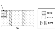
- FIG. 10 is a diagram showing an example of a slot including PSCCH, PSSCH, and DM-RS.
- PSCCH DM-RS is shown at the tip of the arrow.
- FIG. 11 is a diagram for explaining the generation of the PDCCH DM-RS series.
- the provisions for the PDCCH DM-RS series as the provisions for the PSCCH DM-RS series, the following changes or updates may be applied.
- n ID TX-UE ID
- RX-UE TX-UE ID
- mod 2 16 The value of n ID included in the formula for generating the PSCCH DM-RS series may be defined as a specification.
- n ID may be one of ⁇ 0, 1, ..., 65535 ⁇ .
- the value of n ID may be a different value depending on the cast type (eg, broadcast / group cast / unicast).
- the ID of the TX-UE may be referred to as a Source ID, a Group ID, or a Group Source ID
- the ID of the RX-UE may be referred to as a Destination ID, a Group ID, or a Group Destination ID.
- the value of n ID may be set (in advance). For example, one value in ⁇ 0, 1, ..., 65535 ⁇ may be set by a parameter different from the parameter for PDCCH DM-RS.
- the value of n ID may be provided as a parameter of PC5-RRC transmitted / received between the user devices.
- the value of n ID may be determined by combining the above (1), (2), (3) and (4). For example, the above (1) may be applied before the PC5-RRC connection setup, and the above (4) may be applied after the PC5-RRC connection setup.
- n mu s, f For values of n mu s, f included in the formula to produce a sequence of (i) DM-RS, or may be a slot number of the wireless frame of the side links.
- the value of n mu s, f may be a slot number in a subframe in the Quick.
- the value of n mu s, f is the Uu wireless frame or in a sub-frame (i.e., wireless frame or in a sub-frame between the user device and the base station) a slot number It may be (see Uu-based SL scheduling in FIG. 1).
- n ⁇ s, f is, SFN (System frame number) and / or frame number used in the side links (e.g., DFN (direct frame number)) may be determined based on.
- V) the value of n mu s, f may be determined by combining the above (i) (ii) (iii ) (iv). For example, in the case of a carrier in which only the unlicensed spectrum or SL is set, the above (i) is applied, and in the case of a carrier in which the license spectrum (licensed spectrum) or Uu and SL are mixed, the above (iii) is applied. ) May be applied.
- FIG. 12 is a diagram for explaining the mapping of the DM-RS series for PDCCH.
- the mapping of the DM-RS series for PDCCH may be applied, and the following changes or updates may be applied. ..
- the reference point for k or reference point for the parameter k shown in FIG. 12 is at a specific subcarrier in the resource pool (eg, subcarrier 0 in the resource pool). There may be.
- the reference point or reference point for the parameter k may be a specific subcarrier in the subchannel (eg, subcarrier 0 in the sub-channel).
- the reference point or reference point for the parameter k is a specific subcarrier (for example, subcarrier 0 of the least) in the resource block having the lowest number among the resource blocks actually used for PSCCH. -Numered RB in actually-utilized RB for the PSCCH)).
- the reference point or reference point for the parameter k is a specific subcarrier in the common resource block 0 for the side link (eg, subcarrier 0 in the communication block 0 for SL). You may.
- PSSCH DM-RS DM-RS transmitted by PSSCH
- sequence of PSSCH DM-RS is defined as PDSCH (Physical Downlink Shared Channel) or PUSCH (Physical Uplink). It is conceivable to use a series corresponding to the DM-RS series of Shared Channel). In other words, it is conceivable to apply the same provisions for the PDSCH or PUSCH DM-RS series as the provisions for the PSSCH DM-RS series.
- FIG. 13 is a diagram for explaining the generation of the PDSCH DM-RS series.
- N SCID The value of n SCID included in the formula for generating the PSCH DM-RS sequence may be defined as 0 or 1 in the specifications.
- B The value of n SCID may be set (in advance).
- C The value of n SCID may be notified by SCI and / or DCI.
- D The value of n SCID may be determined according to the resource allocation mode (resource transmission mode).
- n SCID is determined without notification by the DM-RS series initialization field in the DCI format for scheduling side links.
- N nSCID ID The value of N nSCID ID included in the formula for generating the PSCH DM-RS series may be determined by the specifications.
- the N nSCID ID may be one of ⁇ 0, 1, ..., 65535 ⁇ .
- the value of N nSCID ID may be a different value depending on the cast type (eg, broadcast / group cast / unicast).
- UE ID mod 2 16 The value of N nSCID ID mod 2 16 ).
- the ID of the TX-UE may be referred to as a Source ID, a Group ID, or a Group Source ID
- the ID of the RX-UE may be referred to as a Destination ID, a Group ID, or a Group Destination ID.
- the value of N nSCID ID may be set (in advance). For example, one value in ⁇ 0, 1, ..., 65535 ⁇ may be set by a parameter different from the parameter for PDSCH.
- the value of N nSCID ID may be provided as a parameter of PC5-RRC transmitted / received between the user devices.
- the value of N nSCID ID may be derived from the information regarding PSCCH.
- N nSCID ID may be determined by combining the above (1), (2), (3), (4), and (5).
- the above (1) may be applied before the PC5-RRC connection setup, and the above (4) may be applied after the PC5-RRC connection setup.
- n mu s, f For values of n mu s, f included in the formula to produce a sequence of (i) PSSCH DM-RS, or may be a slot number of the wireless frame of the side links. (Ii) the value of n mu s, f may be a slot number in a subframe in the Quick. (Iii) the value of n mu s, f is the Uu wireless frame or in a sub-frame (i.e., wireless frame or in a sub-frame between the user device and the base station) a slot number It may be (see Uu-based SL scheduling in FIG. 1).
- n ⁇ s, f is, SFN (System frame number) and / or frame number used in the side links (e.g., DFN (direct frame number)) may be determined based on.
- V) the value of n mu s, f may be determined by combining the above (i) (ii) (iii ) (iv). For example, in the case of a carrier in which only the unlicensed spectrum or SL is set, the above (i) is applied, and in the case of a carrier in which the license spectrum (licensed spectrum) or Uu and SL are mixed, the above (iii) is applied. ) May be applied.
- the complexity of mounting the user device can be reduced.
- FIG. 14 is a diagram for explaining the mapping of the DM-RS series for PDSCH.
- FIG. 15 is a table showing parameters for setting the DM-RS for PDSCH. For mapping of PSCH DM-RS series to side-link physical resources (SL physical resources), apply the mapping of DM-RS series for PDSCH / PUSCH, and apply the following changes or updates. May be good.
- the reference point for k or reference point for the parameter k shown in FIG. 14 is at a specific subcarrier in the resource pool (eg, subcarrier 0 in the resource pool). There may be.
- the reference point or reference point for the parameter k may be a specific subcarrier in the subchannel (eg, subcarrier 0 in the sub-channel).
- the reference point or reference point for the parameter k is a specific subcarrier in the resource block having the lowest number among the resource blocks actually used for PSSCH (for example, subcarrier 0 of the lowest). -Numered RB in actuator-utilized RB for the PSCCH)). (4) The reference point or reference point for the parameter k is a specific subcarrier in the common resource block 0 for the sidelink (eg, subcarrier 0 in the community resource block 0 for SL). You may.
- DM-RS position configuration (sets) of PSCH DM-RS
- TD-CDM Time Division-Code Division Multiplexing
- OCC Orthogonal Cover Code
- wt (l') + 1.
- FD-CDM Frequency Division-Code Division Multiplexing
- the FDM may multiplex the two DM-RS ports.
- Transmission / reception switching gap (TS / RX switching gap) (2) AGC (Automatic Gain Control) (3) Preamble (4) Discovery (Discovery) (5) PSFCH (6) SL-SSB (Synchronization Signal Block)
- the base station apparatus 10 and the user apparatus 20 include a function of carrying out the above-described embodiment.
- the base station apparatus 10 and the user apparatus 20 may each have only a part of the functions in the embodiment.
- FIG. 16 is a diagram showing an example of the functional configuration of the base station apparatus 10.
- the base station apparatus 10 includes a transmission unit 110, a reception unit 120, a setting unit 130, and a control unit 140.
- the functional configuration shown in FIG. 16 is only an example. Any function classification and name of the functional unit may be used as long as the operation according to the embodiment of the present invention can be executed.
- the transmission unit 110 includes a function of generating a signal to be transmitted to the user device 20 side and transmitting the signal wirelessly. In addition, the transmission unit 110 transmits information such as SL scheduling to the user device 20.
- the receiving unit 120 includes a function of receiving various signals transmitted from the user apparatus 20 and acquiring information of, for example, a higher layer from the received signals.
- the setting unit 130 stores preset setting information and various setting information to be transmitted to the user device 20 in the storage device, and reads the setting information from the storage device as needed.
- the content of the setting information is, for example, information related to the setting of V2X.
- control unit 140 performs processing related to the setting for the user device 20 to perform V2X. Further, the function unit related to signal transmission in the control unit 140 may be included in the transmission unit 110, and the function unit related to signal reception in the control unit 140 may be included in the reception unit 120.
- FIG. 17 is a diagram showing an example of the functional configuration of the user device 20.
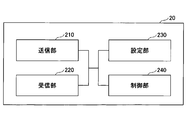
- the user device 20 includes a transmission unit 210, a reception unit 220, a setting unit 230, and a control unit 240.
- the functional configuration shown in FIG. 17 is only an example. Any function classification and name of the functional unit may be used as long as the operation according to the embodiment of the present invention can be executed.
- the transmission unit 210 creates a transmission signal from the transmission data and wirelessly transmits the transmission signal.
- the receiving unit 220 wirelessly receives various signals and acquires a signal of a higher layer from the received signal of the physical layer.
- the transmission unit 210 transmits the side link CSI-RS and DM-RS to the other user device 20.
- the receiving unit 220 has a function of receiving the SL scheduling transmitted from the base station apparatus 10.
- the receiving unit 220 receives the side link CSI-RS and DM-RS from the other user device 20.
- the setting unit 230 stores various setting information received from the base station device 10 or the user device 20 by the receiving unit 220 in the storage device, and reads it out from the storage device as needed.
- the setting unit 230 also stores preset setting information.
- the content of the setting information is, for example, information related to CSI-RS and DM-RS of the side link.
- the control unit 240 controls the D2D communication executed with the other user device 20 as described in the embodiment. In addition, the control unit 240 executes a wireless access procedure with another user device 20.
- the function unit related to signal transmission in the control unit 240 may be included in the transmission unit 210, and the function unit related to signal reception in the control unit 240 may be included in the reception unit 220.
- each functional block may be realized by one device in which a plurality of elements are physically and / or logically combined, or two or more devices physically and / or logically separated from each other directly and. / Or indirectly (eg, wired and / or wireless) may be connected and realized by these plurality of devices.
- both the base station device 10 and the user device 20 in the embodiment of the present invention may function as a computer that performs the processing according to the embodiment of the present invention.
- FIG. 18 is a diagram showing an example of a hardware configuration of a wireless communication device which is a base station device 10 or a user device 20 according to an embodiment of the present invention.
- the above-mentioned base station device 10 and user device 20 are physically as computer devices including a processor 1001, a storage device 1002, an auxiliary storage device 1003, a communication device 1004, an input device 1005, an output device 1006, a bus 1007, and the like. It may be configured.
- the word “device” can be read as a circuit, device, unit, etc.
- the hardware configuration of the base station device 10 and the user device 20 may be configured to include one or more of the devices shown by 1001 to 1006 shown in the figure, or may not include some of the devices. May be done.
- the processor 1001 For each function of the base station device 10 and the user device 20, by loading predetermined software (program) on the hardware such as the processor 1001 and the storage device 1002, the processor 1001 performs an calculation and the communication device 1004 communicates. It is realized by controlling the reading and / or writing of data in the storage device 1002 and the auxiliary storage device 1003.
- the processor 1001 operates, for example, an operating system to control the entire computer.
- the processor 1001 may be composed of a central processing unit (CPU: Central Processing Unit) including an interface with a peripheral device, a control device, an arithmetic unit, a register, and the like.
- CPU Central Processing Unit
- the processor 1001 reads a program (program code), a software module or data from the auxiliary storage device 1003 and / or the communication device 1004 into the storage device 1002, and executes various processes according to these.
- a program program that causes a computer to execute at least a part of the operations described in the above-described embodiment is used.
- the transmission unit 110, the reception unit 120, the setting unit 130, and the control unit 140 of the base station device 10 shown in FIG. 16 may be stored in the storage device 1002 and realized by a control program that operates in the processor 1001.
- 17 are stored in the storage device 1002 and realized by a control program that operates in the processor 1001. May be good. Although it has been described that the various processes described above are executed by one processor 1001, they may be executed simultaneously or sequentially by two or more processors 1001. Processor 1001 may be mounted on one or more chips. The program may be transmitted from the network via a telecommunication line.
- the storage device 1002 is a computer-readable recording medium, and is, for example, at least one of ROM (Read Only Memory), EPROM (Erasable Programmable ROM), EEPROM (Electrically Erasable Programmable ROM), RAM (Random Access Memory), and the like. It may be configured.
- the storage device 1002 may be referred to as a register, a cache, a main memory (main storage device), or the like.
- the storage device 1002 can store a program (program code), a software module, or the like that can be executed to carry out the process according to the embodiment of the present invention.
- the auxiliary storage device 1003 is a computer-readable recording medium, for example, an optical disk such as a CD-ROM (Compact Disc ROM), a hard disk drive, a flexible disk, an optical magnetic disk (for example, a compact disk, a digital versatile disk, Blu).
- -It may be composed of at least one of a ray (registered trademark) disk), a smart card, a flash memory (for example, a card, a stick, a key drive), a floppy (registered trademark) disk, a magnetic strip, and the like.
- the auxiliary storage device 1003 may be referred to as an auxiliary storage device.
- the storage medium described above may be, for example, a database, server or other suitable medium containing the storage device 1002 and / or the auxiliary storage device 1003.
- the communication device 1004 is hardware (transmission / reception device) for communicating between computers via a wired and / or wireless network, and is also referred to as, for example, a network device, a network controller, a network card, a communication module, or the like.
- the transmission unit 110 and the reception unit 120 of the base station device 10 may be realized by the communication device 1004.
- the transmission unit 210 and the reception unit 220 of the user device 20 may be realized by the communication device 1004.
- the input device 1005 is an input device (for example, a keyboard, a mouse, a microphone, a switch, a button, a sensor, etc.) that receives an input from the outside.
- the output device 1006 is an output device (for example, a display, a speaker, an LED lamp, etc.) that outputs to the outside.
- the input device 1005 and the output device 1006 may have an integrated configuration (for example, a touch panel).
- each device such as the processor 1001 and the storage device 1002 is connected by a bus 1007 for communicating information.
- the bus 1007 may be composed of a single bus or may be composed of different buses between the devices.
- the base station device 10 and the user device 20 are a microprocessor, a digital signal processor (DSP: Digital Signal Processor), an ASIC (Application Specific Integrated Circuit), a PLD (Programmable Logic Device), an FPGA (Field Programmable Gate Array), etc., respectively. It may be configured to include the hardware of, and a part or all of each functional block may be realized by the hardware. For example, processor 1001 may be implemented on at least one of these hardware.
- a control unit that generates a sequence corresponding to a sequence of reference signals between base station terminals and a reference signal having the generated sequence are transmitted to other terminals.
- a terminal having a transmitter and a terminal for
- the above configuration provides a technique for defining a reference signal in the NR side link (NR-SL).
- the boundary of the functional unit or the processing unit in the functional block diagram does not always correspond to the boundary of the physical component.
- the operation of the plurality of functional units may be physically performed by one component, or the operation of one functional unit may be physically performed by a plurality of components. With respect to the processing procedure described in the embodiment, the order of processing may be changed as long as there is no contradiction.
- the base station device 10 and the user device 20 have been described with reference to functional block diagrams, but such devices may be implemented in hardware, software, or a combination thereof.
- the software operated by the processor of the base station apparatus 10 according to the embodiment of the present invention and the software operated by the processor of the user apparatus 20 according to the embodiment of the present invention are random access memory (RAM), flash memory, and read, respectively. It may be stored in a dedicated memory (ROM), EPROM, EEPROM, registers, hard disk (HDD), removable disk, CD-ROM, database, server or any other suitable storage medium.
- information notification includes physical layer signaling (for example, DCI (Downlink Control Information), UCI (Uplink Control Information)), higher layer signaling (for example, RRC (Radio Resource Control) signaling, MAC (Medium Access Control) signaling, etc. Broadcast information (MIB (Master Information Block), SIB (System Information Block)), other signals, or a combination thereof may be used.
- RRC signaling may be referred to as an RRC message, for example, RRC. It may be a connection setup (RRCConnectionSetup) message, an RRC connection reconfiguration (RRCConnectionReconfiguration) message, or the like.
- Each aspect / embodiment described in the present specification includes LTE (LongTermEvolution), LTE-A (LTE-Advanced), SUPER 3G, IMT-Advanced, 4G, 5G, FRA (FutureRadioAccess), W-CDMA. (Registered Trademarks), GSM (Registered Trademarks), CDMA2000, UMB (Ultra-Mobile Broadband), IEEE 802.11 (Wi-Fi), IEEE 802.16 (WiMAX), LTE 802.20, UWB (Ultra-WideBand), It may be applied to Bluetooth®, other systems that utilize suitable systems and / or next-generation systems that are extended based on them.
- the specific operation performed by the base station apparatus 10 in the present specification may be performed by its upper node (upper node).
- various operations performed for communication with the user device 20 are other than the base station device 10 and / or the base station device 10. It is clear that it can be done by other network nodes, such as, but not limited to, MME or S-GW.
- MME Mobility Management Entity
- S-GW Serving Mobility Management Entity
- the user device 20 may be a subscriber station, a mobile unit, a subscriber unit, a wireless unit, a remote unit, a mobile device, a wireless device, a wireless communication device, a remote device, a mobile subscriber station, an access terminal, a mobile terminal, etc. It may also be referred to as a wireless terminal, remote terminal, handset, user agent, mobile client, client, or some other suitable term.
- the base station apparatus 10 may be referred to by those skilled in the art by NB (NodeB), eNB (evolvedNodeB), gNB, BaseStation, or some other suitable term.
- NB NodeB
- eNB evolvedNodeB
- gNB BaseStation
- determining and “determining” used in this specification may include a wide variety of actions.
- “Judgment” and “decision” are, for example, judgment (judging), calculation (calculating), calculation (computing), processing (processing), derivation (deriving), investigating (investigating), and searching (looking up) (for example, a table).
- Searching in a database or another data structure), confirming (ascertaining) may be regarded as “judgment” or “decision”.
- judgment and “decision” are receiving (for example, receiving information), transmitting (for example, transmitting information), input (input), output (output), and access.
- Base station device 110 Transmission unit 120 Reception unit 130 Setting unit 140 Control unit 20 User device 210 Transmission unit 220 Reception unit 230 Setting unit 240 Control unit 1001 Processor 1002 Storage device 1003 Auxiliary storage device 1004 Communication device 1005 Input device 1006 Output device
Landscapes
- Engineering & Computer Science (AREA)
- Signal Processing (AREA)
- Computer Networks & Wireless Communication (AREA)
- Mobile Radio Communication Systems (AREA)
Abstract
Description
NR-V2Xにおけるサイドリンク送信モードについて説明する。
本発明の実施形態として、サイドリンクにおけるCSI-RS(以下、SL-CSI-RSとも称する)について、SL-CSI-RSの系列(sequence)を、基地局端末間のCSI-RS(UuのCSI-RS)の系列に対応する系列とすることが考えられる。言い換えると、基地局端末間のCSI-RS(UuのCSI-RS)の系列に対する規定と同様の規定を、SL-CSI-RSの系列に対する規定として適用することが考えられる。なお、SL-CSI-RSは、例えばSRS(Sounding Reference Signal)又はサイドリンクにおけるSRS(SL-SRS)と呼ばれてもよいし、同様の目的で用いられる別の信号であってもよい。
図2は、基地局端末間のCSI-RS(UuのCSI-RS)の系列の生成を説明するための図である。図2に示されるように、参照信号CSI-RSの系列r(m)の式には、疑似ランダム系列c(i)が含まれ、疑似ランダム系列生成はcinitによって初期化される。cinitの式には、nID、nμ s、f、lが含まれている。nIDは、上位レイヤパラメータのscramblingIDまたはsequenceGenerationConfigに対応し、nμ s、fは、無線フレーム内のスロット番号に対応し、lは、スロット内のOFDMシンボル番号に対応している。基地局端末間のCSI-RSの系列に対する規定をSL-CSI-RSの系列に対する規定として適用する際に、以下に示すような変更または更新を適用してもよい。
(nID)
(1)SL-CSI-RSの系列を生成する式に含まれるnIDの値について、仕様として定義してもよい。例えば、nIDは、{0、1、...、1023}の中の一つの値であってもよい。あるいは、nIDの値は、キャスト種別(例:ブロードキャスト/グループキャスト/ユニキャスト)に応じた異なる値であってもよい。
(2)nIDの値は、送信側ユーザ装置(TX-UE)のIDまたは受信側ユーザ装置(RX-UE)のIDに応じて決定されてもよい(例:nID=TX-UE ID mod 210)。TX-UEのIDはSource IDやGroup ID、Group Source IDと呼ばれてもよいし、RX-UEのIDはDestination IDやGroup ID、Group Destination IDと呼ばれてもよい。
(3)nIDの値は、(事前に)設定されてもよい。例えば、{0、1、...、1023}の中の一つの値が、下りリンクCSI-RS用のパラメータとは異なるパラメータによって設定されてもよい。
(4)nIDの値は、ユーザ装置間で送受信されるパラメータとして提供されてもよい。例えば、PC5-RRCメッセージのパラメータとして提供されてもよい。なお、PC5-RRCのパラメータは、UE間で行われる上位レイヤの接続(例えば、RRCコネクション)において、UE間で送受信される上位レイヤパラメータを意味してもよい。
(5)nIDの値は、上記(1)(2)(3)(4)を組み合わせて決定されてもよい。例えば、PC5-RRC connection setupより前には、上記(1)を適用し、PC5-RRC connection setup後には、上記(4)を適用してもよい。あるいは、上記(1)(2)(3)(4)における複数の値を組み合わせて1つの値として用いてもよい。なお、PC5-RRC connection setupは、UE間で行われる上位レイヤの接続を意味してもよい。UE間で行われる上位レイヤの接続は、Unicast通信やGroupcast通信のために行われてもよい。
(i)SL-CSI-RSの系列を生成する式に含まれるnμ s、fの値について、サイドリンクの(無線)フレーム内のスロット番号であってもよい。
(ii)nμ s、fの値は、サイドリンクのサブフレーム内のスロット番号であってもよい。
(iii)nμ s、fの値は、Uuの(無線)フレームまたはサブフレーム内の(すなわち、ユーザ装置と基地局との間の(無線)フレームまたはサブフレーム内の)スロット番号であってもよい(図1におけるUu-based SL scheduling参照)。
(iv)nμ s、fの値は、SFN(System frame number)および/またはサイドリンクで使用されるframe number(例えば、DFN(direct frame number))に基づいて決定されてもよい。
(v)nμ s、fの値は、上記(i)(ii)(iii)(iv)を組み合わせて決定されてもよい。例えば、アンライセンス スペクトラム(unlicensed spectrum)又はSLのみが設定されたキャリアの場合は、上記(i)を適用し、ライセンス スペクトラム(licensed spectrum)又はUuとSLが混在するキャリアの場合は、上記(iii)を適用してもよい。なお、フレームおよびサブフレームについては、既存のフレームおよびサブフレームだけではなく、既存のフレームおよびサブフレームとは異なる時間リソースであってもよい。
SL-CSI-RSの系列を生成する式に含まれるnIDの値の範囲は広げる、または、狭めることができる(例:{0、1、...、65535})。
この場合、cinitの式は、図2における式に代えて、例えば、以下のような式とすることができる。

図3は、NR-UuのCSI-RSの系列のマッピングを説明するための図である。図4は、NR-UuのCSI-RSの系列を示す表である。図5は、NR-Uuのスロット内のCSI-RSの位置を示す表である。
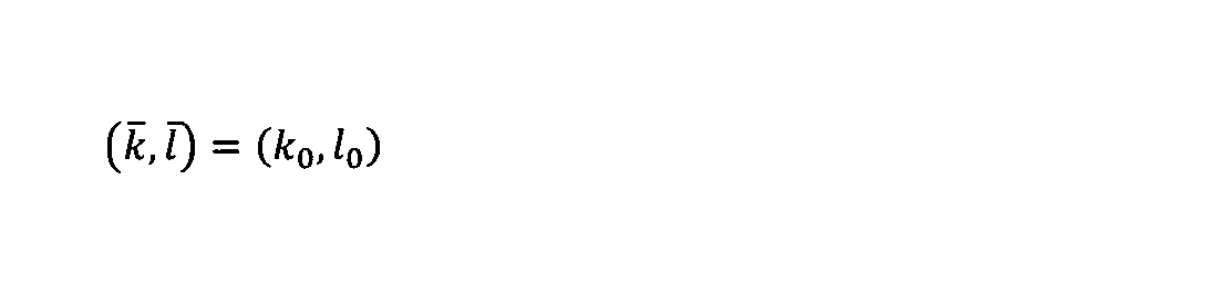
(1)SL-CSI-RSの時間領域リソースについては、PSSCHの最後のシンボルに固定されてもよい。例えば、パラメータfirstOFDMSymbolInTimeDomain、l0=13であってもよいし、PSSCHとして利用可能な最後のシンボルに固定されてもよい。パラメータfirstOFDMSymbolInTimeDomain2、l1は規定されなくてもよい。
(2)SL-CSI-RSの時間領域リソースは、(事前に)設定されてもよい。
(3)SL-CSI-RSの時間領域リソースは、SCI(Sidelink Control Information)および/またはDCI(Downlink Control Information)によって通知されてもよい。例えば、サイドリンク送信モード1の場合に、基地局装置10から送信されるDCIによってSL-CSI-RSリソースが通知され、さらに、ユーザ装置20から送信されるSCIによって、DCIによって通知されたリソースにおける位置等が通知されてもよい。
(4)SL-CSI-RSの時間領域リソースは、DM-RSの設定(例:DM-RSの時間領域の位置)に基づいて決定されてもよい。
(5)SL-CSI-RSの時間領域リソースは、PC5-RRCのパラメータとして提供されてもよい。
なお、SL-CSI-RSの時間領域リソースは明示的に指示されてもよいし、暗示的に指示されてもよい。また、SL-CSI-RSの時間領域リソースは、上記(1)(2)(3)(4)(5)を組み合わせて決定されてもよい。
パラメータfrequencyDomainAllocation、k0、k1、k2、k3
パラメータcdm-Type
パラメータnrofPorts
パラメータdensity
すなわち、例えばSL-CSI-RSの周波数領域リソースは、以下の何れかに基づいて決定されてもよい。
(1)SL-CSI-RSの周波数領域リソースについては、PSSCHの特定のサブキャリアに固定されてもよい。例えば、パラメータfrequencyDomainAllocation、k0=0であってもよい。また、一つ又は複数のRow毎に設定されてもよい。
(2)SL-CSI-RSの周波数領域リソースは、(事前に)設定されてもよい。
(3)SL-CSI-RSの周波数領域リソースは、SCI(Sidelink Control Information)および/またはDCI(Downlink Control Information)によって通知されてもよい。
(4)SL-CSI-RSの周波数領域リソースは、DM-RSの設定(例:DM-RSの位置)に基づいて決定されてもよい。
(5)SL-CSI-RSの周波数領域リソースは、PC5-RRCのパラメータとして提供されてもよい。
なお、SL-CSI-RSの周波数領域リソースは明示的に指示されてもよいし、暗示的に指示されてもよい。また、SL-CSI-RSの周波数領域リソースは、上記(1)(2)(3)(4)(5)を組み合わせて決定されてもよい。
(1)図3に示されたパラメータkのための参照ポイント(reference point for k)又は基準点は、リソースプールにおける特定のサブキャリア(例えば、サブキャリア0(subcarrier 0 in the resource pool))であってもよい。
(2)パラメータkのための参照ポイント又は基準点は、サブチャネルにおける特定のサブキャリア(例えば、サブキャリア0(subcarrier 0 in the sub-channel))であってもよい。
(3)パラメータkのための参照ポイント又は基準点は、実際にPSCCHに利用されたリソースブロックの中で最も番号の小さいリソースブロックにおける特定のサブキャリア(例えば、サブキャリア0(subcarrier 0 of the lowest-numbered RB in actually-utilized RB for the PSCCH))であってもよい。
(4)パラメータkのための参照ポイント又は基準点は、サイドリンクのための共通リソースブロック0における特定のサブキャリア(例えば、サブキャリア0(subcarrier 0 in the common resource block 0 for SL))であってもよい。
図6は、PSCCH、PSSCH、DM-RS、CSI-RSを含むスロットの一例を示す図である。
(1)周期的および/又は準パーシステントなSL-CSI-RSを設定/指示する際に、リソースブロックレベル(サブチャネルレベル)の周波数領域のリソースは提供されなくてもよい。例えば、図7に示されるように、周期性/オフセットに基づいて周期的SL-CSI-RSが或るスロット上でユーザ装置20に送信される場合において、そのスロット上でPSCCH/PSSCHが送信される場合には、該スロット上のPSCCH/PSSCHと同じサブチャネルでSL-CSI-RSが送信され、そのスロット上でPSCCH/PSSCHが送信されない場合には、(いずれのサブチャネルでも)SL-CSI-RSは送信されなくてもよい。このような設定により、スロット上でSL-CSI-RSだけが無駄に送信されることを防ぐことができる。
(2)周期的および/又は準パーシステントなSL-CSI-RSを設定/指示する際に、リソースブロックレベル(サブチャネルレベル)の周波数領域のリソースが提供されてもよい。例えば、図8に示されるように、周期性/オフセットに基づいて周期的SL-CSI-RSが或るスロット上でユーザ装置20に送信される場合において、そのスロット上でPSCCH/PSSCHが送信される場合には、該スロット上のPSCCH/PSSCHと同じサブチャネルでSL-CSI-RSが送信され、そのスロット上でPSCCH/PSSCHが送信されない場合には、設定された周波数領域のリソース上でSL-CSI-RSが送信されてもよい。このような設定により、SL-CSI-RSが周期的に送信され、より良いCSIが得られる。また、周波数方向に非連続な信号送信を回避し、PSCCH/PSSCH送信への影響を低減できる。なお、周期性/オフセットに基づいて周期的SL-CSI-RSが或るスロット上でユーザ装置20に送信される場合において、そのスロット上でPSCCH/PSSCHが送信される場合にも、設定された周波数領域のリソース上でSL-CSI-RSが送信されてもよい。
(i)例えば、SCIの中の1ビットを用いて、スケジューリングされたPSSCHにおけるSL-CSI-RSの有無を通知してもよい。
(ii)あるいは、SCIの中の複数のビットを用いて、スケジューリングされたPSSCHにおけるSL-CSI-RSの有無及び/又は送信されるSL-CSI-RS構成を通知してもよい。
(a)SL-CSI-RSは、複数のスロット上のPSSCHの中の、特定のスロット(例:最初のスロット、最後のスロット、SL-CSI-RS機会のスロット(SL-CSI-RS occasion slot(s)))にだけマッピングされてもよい。
(b)SL-CSI-RSは、複数のスロットにわたるPSSCHの、すべてのスロット上にマッピングされてもよい。各スロットにマッピングされるSL-CSI-RSの構成(configuration)(例えば、系列、マッピングリソース等)は、すべて同じであってもよいし、スロット毎に異なってもよい。例えば、スロットインデックス(slot index)に基づく構成であってもよい。
本発明の実施形態として、PSCCHで送信されるDM-RS(以下、PSCCH DM-RSと称する)について、PSCCH DM-RSの系列(sequence)を、PDCCH DM-RSの系列に対応する系列とすることが考えられる。言い換えると、PDCCH DM-RSの系列に対する規定と同様の規定を、PSCCH DM-RSの系列に対する規定として適用することが考えられる。
(1)PSCCH DM-RSの系列を生成する式に含まれるnIDの値について、仕様として定義してもよい。例えば、nIDは、{0、1、...、65535}の中の一つの値であってもよい。あるいは、nIDの値は、キャスト種別(例:ブロードキャスト/グループキャスト/ユニキャスト)に応じた異なる値であってもよい。
(2)nIDの値は、送信側ユーザ装置(TX-UE)のIDまたは受信側ユーザ装置(RX-UE)のIDに応じて決定されてもよい(例:nID=TX-UE ID mod 216)。TX-UEのIDはSource IDやGroup ID、Group Source IDと呼ばれてもよいし、RX-UEのIDはDestination IDやGroup ID、Group Destination IDと呼ばれてもよい。
(3)nIDの値は、(事前に)設定されてもよい。例えば、{0、1、...、65535}の中の一つの値が、PDCCH DM-RS用のパラメータとは異なるパラメータによって設定されてもよい。
(4)nIDの値は、ユーザ装置間で送受信されるPC5-RRCのパラメータとして提供されてもよい。
(5)nIDの値は、上記(1)(2)(3)(4)を組み合わせて決定されてもよい。例えば、PC5-RRC connection setupより前には、上記(1)を適用し、PC5-RRC connection setup後には、上記(4)を適用してもよい。
(i)DM-RSの系列を生成する式に含まれるnμ s、fの値について、サイドリンクの(無線)フレーム内のスロット番号であってもよい。
(ii)nμ s、fの値は、サイドリンクのサブフレーム内のスロット番号であってもよい。
(iii)nμ s、fの値は、Uuの(無線)フレームまたはサブフレーム内の(すなわち、ユーザ装置と基地局との間の(無線)フレームまたはサブフレーム内の)スロット番号であってもよい(図1におけるUu-based SL scheduling参照)。
(iv)nμ s、fの値は、SFN(System frame number)および/またはサイドリンクで使用されるframe number(例えば、DFN(direct frame number))に基づいて決定されてもよい。
(v)nμ s、fの値は、上記(i)(ii)(iii)(iv)を組み合わせて決定されてもよい。例えば、アンライセンス スペクトラム(unlicensed spectrum)又はSLのみが設定されたキャリアの場合は、上記(i)を適用し、ライセンス スペクトラム(licensed spectrum)又はUuとSLが混在するキャリアの場合は、上記(iii)を適用してもよい。
(1)図12に示されたパラメータkのための参照ポイント(reference point for k)又は基準点は、リソースプールにおける特定のサブキャリア(例えば、サブキャリア0(subcarrier 0 in the resource pool))であってもよい。
(2)パラメータkのための参照ポイント又は基準点は、サブチャネルにおける特定のサブキャリア(例えば、サブキャリア0(subcarrier 0 in the sub-channel))であってもよい。
(3)パラメータkのための参照ポイント又は基準点は、実際にPSCCHに利用されたリソースブロックの中で最も番号の小さいリソースブロックにおける特定のサブキャリア(例えば、サブキャリア0(subcarrier 0 of the lowest-numbered RB in actually-utilized RB for the PSCCH))であってもよい。
(4)パラメータkのための参照ポイント又は基準点は、サイドリンクのための共通リソースブロック0における特定のサブキャリア(例えば、サブキャリア0(subcarrier 0 in the common resource block 0 for SL))であってもよい。
本発明の実施形態として、PSSCHで送信されるDM-RS(以下、PSSCH DM-RSと称する)について、PSSCH DM-RSの系列(sequence)を、PDSCH(Physical Downlink Shared Channel)またはPUSCH(Physical Uplink Shared Channel)のDM-RSの系列に対応する系列とすることが考えられる。言い換えると、PDSCHまたはPUSCHのDM-RSの系列に対する規定と同様の規定を、PSSCH DM-RSの系列に対する規定として適用することが考えられる。
(a)PSSCH DM-RSの系列を生成する式に含まれるnSCIDの値について、仕様において、0または1と定義してもよい。
(b)nSCIDの値は、(事前に)設定されてもよい。
(c)nSCIDの値は、SCIおよび/またはDCIによって通知されてもよい。
(d)nSCIDの値は、リソース割当てモード(リソース送信モード)に応じて決定されてもよい。
(1)PSSCH DM-RSの系列を生成する式に含まれるNnSCID IDの値について、仕様で決められてもよい。例えば、NnSCID IDは、{0、1、...、65535}の中の一つの値であってもよい。あるいは、NnSCID IDの値は、キャスト種別(例:ブロードキャスト/グループキャスト/ユニキャスト)に応じた異なる値であってもよい。
(2)NnSCID IDの値は、送信側ユーザ装置(TX-UE)のIDまたは受信側ユーザ装置(RX-UE)のIDに応じて決定されてもよい(例:NnSCID ID=TX-UE ID mod 216)。TX-UEのIDはSource IDやGroup ID、Group Source IDと呼ばれてもよいし、RX-UEのIDはDestination IDやGroup ID、Group Destination IDと呼ばれてもよい。
(3)NnSCID IDの値は、(事前に)設定されてもよい。例えば、{0、1、...、65535}の中の一つの値が、PDSCH用のパラメータとは異なるパラメータによって設定されてもよい。
(4)NnSCID IDの値は、ユーザ装置間で送受信されるPC5-RRCのパラメータとして提供されてもよい。
(5)NnSCID IDの値は、PSCCHに関する情報から導出されてもよい。例えば、PSCCHをスクランブルするCRC(CRC scrambling PSCCH)から導出されてもよい。例えば、HPN(HARQ Process Number又はHARQ Process IDと呼ばれてもよい)、NDI(New Data Indicator)、RV(Redundancy Version)、周波数領域リソース、MCS(Modulation Coding Scheme)等から導出されてもよい。
(6)NnSCID IDの値は、上記(1)(2)(3)(4)(5)を組み合わせて決定されてもよい。例えば、PC5-RRC connection setupより前には、上記(1)を適用し、PC5-RRC connection setup後には、上記(4)を適用してもよい。
(i)PSSCH DM-RSの系列を生成する式に含まれるnμ s、fの値について、サイドリンクの(無線)フレーム内のスロット番号であってもよい。
(ii)nμ s、fの値は、サイドリンクのサブフレーム内のスロット番号であってもよい。
(iii)nμ s、fの値は、Uuの(無線)フレームまたはサブフレーム内の(すなわち、ユーザ装置と基地局との間の(無線)フレームまたはサブフレーム内の)スロット番号であってもよい(図1におけるUu-based SL scheduling参照)。
(iv)nμ s、fの値は、SFN(System frame number)および/またはサイドリンクで使用されるframe number(例えば、DFN(direct frame number))に基づいて決定されてもよい。
(v)nμ s、fの値は、上記(i)(ii)(iii)(iv)を組み合わせて決定されてもよい。例えば、アンライセンス スペクトラム(unlicensed spectrum)又はSLのみが設定されたキャリアの場合は、上記(i)を適用し、ライセンス スペクトラム(licensed spectrum)又はUuとSLが混在するキャリアの場合は、上記(iii)を適用してもよい。
(1)図14に示されたパラメータkのための参照ポイント(reference point for k)又は基準点は、リソースプールにおける特定のサブキャリア(例えば、サブキャリア0(subcarrier 0 in the resource pool))であってもよい。
(2)パラメータkのための参照ポイント又は基準点は、サブチャネルにおける特定のサブキャリア(例えば、サブキャリア0(subcarrier 0 in the sub-channel))であってもよい。
(3)パラメータkのための参照ポイント又は基準点は、実際にPSSCHに利用されたリソースブロックの中で最も番号の小さいリソースブロックにおける特定のサブキャリア(例えば、サブキャリア0(subcarrier 0 of the lowest-numbered RB in actually-utilized RB for the PSCCH))であってもよい。
(4)パラメータkのための参照ポイント又は基準点は、サイドリンクのための共通リソースブロック0における特定のサブキャリア(例えば、サブキャリア0(subcarrier 0 in the common resource block 0 for SL))であってもよい。
(1)送信/受信切り替えギャップ(TS/RX switching gap)
(2)AGC(Automatic Gain Control)
(3)プリアンブル(Preamble)
(4)発見(Discovery)
(5)PSFCH
(6)SL-SSB(Synchronization Signal Block)
次に、これまでに説明した処理及び動作を実行する基地局装置10及びユーザ装置20の機能構成例を説明する。基地局装置10及びユーザ装置20は上述した実施例を実施する機能を含む。ただし、基地局装置10及びユーザ装置20はそれぞれ、実施例の中の一部の機能のみを備えることとしてもよい。
図16は、基地局装置10の機能構成の一例を示す図である。図16に示されるように、基地局装置10は、送信部110と、受信部120と、設定部130と、制御部140とを有する。図16に示される機能構成は一例に過ぎない。本発明の実施の形態に係る動作を実行できるのであれば、機能区分及び機能部の名称はどのようなものでもよい。
図17は、ユーザ装置20の機能構成の一例を示す図である。図17に示されるように、ユーザ装置20は、送信部210と、受信部220と、設定部230と、制御部240とを有する。図17に示される機能構成は一例に過ぎない。本発明の実施の形態に係る動作を実行できるのであれば、機能区分及び機能部の名称はどのようなものでもよい。
上述の本発明の実施の形態の説明に用いた機能構成図(図16及び図17)は、機能単位のブロックを示している。これらの機能ブロック(構成部)は、ハードウェア及び/又はソフトウェアの任意の組み合わせによって実現される。また、各機能ブロックの実現手段は特に限定されない。すなわち、各機能ブロックは、物理的及び/又は論理的に複数要素が結合した1つの装置により実現されてもよいし、物理的及び/又は論理的に分離した2つ以上の装置を直接的及び/又は間接的に(例えば、有線及び/又は無線)で接続し、これら複数の装置により実現されてもよい。
以上、説明したように、本発明の実施形態によれば、基地局端末間の参照信号の系列に対応する系列を生成する制御部と、生成した前記系列を有する参照信号を他の端末に送信する送信部と、を有する端末が提供される。
以上、本発明の実施の形態を説明してきたが、開示される発明はそのような実施形態に限定されず、当業者は様々な変形例、修正例、代替例、置換例等を理解するであろう。発明の理解を促すため具体的な数値例を用いて説明がなされたが、特に断りのない限り、それらの数値は単なる一例に過ぎず適切な如何なる値が使用されてもよい。上記の説明における項目の区分けは本発明に本質的ではなく、2以上の項目に記載された事項が必要に応じて組み合わせて使用されてよいし、ある項目に記載された事項が、別の項目に記載された事項に(矛盾しない限り)適用されてよい。機能ブロック図における機能部又は処理部の境界は必ずしも物理的な部品の境界に対応するとは限らない。複数の機能部の動作が物理的には1つの部品で行われてもよいし、あるいは1つの機能部の動作が物理的には複数の部品により行われてもよい。実施の形態で述べた処理手順については、矛盾の無い限り処理の順序を入れ替えてもよい。処理説明の便宜上、基地局装置10及びユーザ装置20は機能的なブロック図を用いて説明されたが、そのような装置はハードウェアで、ソフトウェアで又はそれらの組み合わせで実現されてもよい。本発明の実施の形態に従って基地局装置10が有するプロセッサにより動作するソフトウェア及び本発明の実施の形態に従ってユーザ装置20が有するプロセッサにより動作するソフトウェアはそれぞれ、ランダムアクセスメモリ(RAM)、フラッシュメモリ、読み取り専用メモリ(ROM)、EPROM、EEPROM、レジスタ、ハードディスク(HDD)、リムーバブルディスク、CD-ROM、データベース、サーバその他の適切な如何なる記憶媒体に保存されてもよい。
110 送信部
120 受信部
130 設定部
140 制御部
20 ユーザ装置
210 送信部
220 受信部
230 設定部
240 制御部
1001 プロセッサ
1002 記憶装置
1003 補助記憶装置
1004 通信装置
1005 入力装置
1006 出力装置
Claims (6)
- 基地局端末間のチャネル状態情報のための参照信号の系列に対応するサイドリンクの参照信号の系列を生成する制御部と、
生成した前記系列を有する前記サイドリンクの参照信号を他の端末に送信する送信部と、
を有する端末。 - 前記サイドリンクの参照信号の最大ポート数は2である、
請求項1に記載の端末。 - 前記サイドリンクの参照信号の有無及び構成の少なくとも何れかは、複数のスロットにわたるPSSCH(Physical Sidelink Shared Channel)送信を通知するSCI(Sidelink Contol Information)によって設定される、
請求項1に記載の端末。 - 前記サイドリンクの参照信号は、前記複数のスロットの中の、すべてのスロットまたは特定のスロットにマッピングされる、
請求項3に記載の端末。 - 前記複数のスロットのすべてのスロットまたは特定のスロットにマッピングされる前記参照信号の構成は、スロット毎に異なる、
請求項4に記載の端末。 - 基地局端末間のチャネル状態情報のための参照信号の系列に対応するサイドリンクの参照信号の系列を生成する生成ステップと、
生成した前記系列を有する前記サイドリンクの参照信号を他の端末に送信する送信ステップと、
を有する端末の通信方法。
Priority Applications (6)
| Application Number | Priority Date | Filing Date | Title |
|---|---|---|---|
| CN201980098205.9A CN114175782A (zh) | 2019-07-08 | 2019-07-08 | 终端及通信方法 |
| CA3143226A CA3143226A1 (en) | 2019-07-08 | 2019-07-08 | Terminal and communication method |
| JP2021530384A JP7317114B2 (ja) | 2019-07-08 | 2019-07-08 | ユーザ装置及び通信方法 |
| PCT/JP2019/027059 WO2021005696A1 (ja) | 2019-07-08 | 2019-07-08 | 端末及び通信方法 |
| EP19936623.8A EP3998811A4 (en) | 2019-07-08 | 2019-07-08 | TERMINAL AND COMMUNICATION METHOD |
| US17/597,273 US12143326B2 (en) | 2019-07-08 | 2019-07-08 | Terminal and communication method |
Applications Claiming Priority (1)
| Application Number | Priority Date | Filing Date | Title |
|---|---|---|---|
| PCT/JP2019/027059 WO2021005696A1 (ja) | 2019-07-08 | 2019-07-08 | 端末及び通信方法 |
Publications (1)
| Publication Number | Publication Date |
|---|---|
| WO2021005696A1 true WO2021005696A1 (ja) | 2021-01-14 |
Family
ID=74113943
Family Applications (1)
| Application Number | Title | Priority Date | Filing Date |
|---|---|---|---|
| PCT/JP2019/027059 Ceased WO2021005696A1 (ja) | 2019-07-08 | 2019-07-08 | 端末及び通信方法 |
Country Status (6)
| Country | Link |
|---|---|
| US (1) | US12143326B2 (ja) |
| EP (1) | EP3998811A4 (ja) |
| JP (1) | JP7317114B2 (ja) |
| CN (1) | CN114175782A (ja) |
| CA (1) | CA3143226A1 (ja) |
| WO (1) | WO2021005696A1 (ja) |
Families Citing this family (5)
| Publication number | Priority date | Publication date | Assignee | Title |
|---|---|---|---|---|
| CN110535611B (zh) * | 2019-08-14 | 2025-02-11 | 中兴通讯股份有限公司 | 信号发送、接收、信息反馈方法、装置、通信节点及介质 |
| KR102859038B1 (ko) * | 2019-09-30 | 2025-09-11 | 후아웨이 테크놀러지 컴퍼니 리미티드 | 통신 방법 및 장치 |
| WO2021062608A1 (zh) * | 2019-09-30 | 2021-04-08 | 华为技术有限公司 | 用于确定信道状态信息参考信号资源映射的方法及装置 |
| CN112769525A (zh) * | 2019-11-06 | 2021-05-07 | 维沃移动通信有限公司 | 旁链路csi上报控制方法、旁链路csi上报方法及相关设备 |
| WO2024206867A1 (en) * | 2023-03-31 | 2024-10-03 | Apple Inc. | Enhanced sidelink csi-rs transmissions for beam measurement |
Citations (2)
| Publication number | Priority date | Publication date | Assignee | Title |
|---|---|---|---|---|
| WO2014126022A1 (ja) * | 2013-02-12 | 2014-08-21 | 京セラ株式会社 | 移動通信システム、通信装置、及びd2d端末 |
| WO2018012614A1 (ja) * | 2016-07-15 | 2018-01-18 | シャープ株式会社 | 端末装置および方法 |
Family Cites Families (1)
| Publication number | Priority date | Publication date | Assignee | Title |
|---|---|---|---|---|
| JP2019149593A (ja) * | 2016-07-15 | 2019-09-05 | シャープ株式会社 | 端末装置および方法 |
-
2019
- 2019-07-08 JP JP2021530384A patent/JP7317114B2/ja active Active
- 2019-07-08 CA CA3143226A patent/CA3143226A1/en active Pending
- 2019-07-08 EP EP19936623.8A patent/EP3998811A4/en active Pending
- 2019-07-08 US US17/597,273 patent/US12143326B2/en active Active
- 2019-07-08 CN CN201980098205.9A patent/CN114175782A/zh not_active Withdrawn
- 2019-07-08 WO PCT/JP2019/027059 patent/WO2021005696A1/ja not_active Ceased
Patent Citations (2)
| Publication number | Priority date | Publication date | Assignee | Title |
|---|---|---|---|---|
| WO2014126022A1 (ja) * | 2013-02-12 | 2014-08-21 | 京セラ株式会社 | 移動通信システム、通信装置、及びd2d端末 |
| WO2018012614A1 (ja) * | 2016-07-15 | 2018-01-18 | シャープ株式会社 | 端末装置および方法 |
Non-Patent Citations (4)
| Title |
|---|
| ITL: "DM-RS sequence for PSCCH/PSSCH/PSBCH in V2V", 3GPP TSG-RAN WG1#86 R1-167750, 22 August 2016 (2016-08-22), XP051054005, Retrieved from the Internet <URL:http://www.3gpp.org/ftp/tsg_ran/WG1_RL1/TSGR1_1744/Docs/R1-167750.zip> * |
| LG ELECTRONICS: "Remaining details on DMRS for PSBCH", 3GPP TSG-RAN WG1#86 R1-166822, 22 August 2016 (2016-08-22), XP051125579, Retrieved from the Internet <URL:http://www.3gpp.org/ftp/tsg_ran/WG1_RL1/TSGR1_839/Docs/R1-166822.zip> * |
| See also references of EP3998811A4 * |
| SONY: "Discussion on DMRS enhancement and operation for V2V", 3GPP TSG-RAN WG1#84 R1-160677, 15 February 2016 (2016-02-15), XP051054005, Retrieved from the Internet <URL:http://www.3gpp.org/ftp/tsg_ran/WG1_RL1/TSGR1_84/Docs/R1-160677.zip> * |
Also Published As
| Publication number | Publication date |
|---|---|
| US12143326B2 (en) | 2024-11-12 |
| US20220321291A1 (en) | 2022-10-06 |
| CA3143226A1 (en) | 2021-01-14 |
| EP3998811A1 (en) | 2022-05-18 |
| EP3998811A4 (en) | 2023-03-08 |
| JPWO2021005696A1 (ja) | 2021-01-14 |
| JP7317114B2 (ja) | 2023-07-28 |
| CN114175782A (zh) | 2022-03-11 |
Similar Documents
| Publication | Publication Date | Title |
|---|---|---|
| EP3986020B1 (en) | User equipment | |
| JP7317114B2 (ja) | ユーザ装置及び通信方法 | |
| US12598028B2 (en) | Communication apparatus and communication method | |
| CN110167040A (zh) | 无线通信系统中的装置和方法、计算机可读存储介质 | |
| JPWO2019049348A1 (ja) | ユーザ装置、及び能力情報通知方法 | |
| JP7078534B2 (ja) | 端末、無線通信方法、基地局及びシステム | |
| US12137065B2 (en) | Terminal and communication method | |
| JP7009369B2 (ja) | 基地局及び信号送信方法 | |
| JP7829003B2 (ja) | 端末、通信方法及び通信システム | |
| US20200195317A1 (en) | User apparatus and communication method | |
| EP3457742A1 (en) | User terminal and wireless communication method | |
| JP7140129B2 (ja) | 無線通信装置、無線通信方法およびコンピュータプログラム | |
| US20220173828A1 (en) | User apparatus and communication method | |
| EP3214779A1 (en) | Communication control device, wireless communication device, communication control method, wireless communication method and program | |
| US11140747B2 (en) | Base station and user apparatus | |
| CN117322083A (zh) | 用于半持久调度(sps)混合自动重传请求(harq)跳过的上行链路控制信息(uci)复用 | |
| CN103313392B (zh) | 处理控制信道的方法及其通讯装置 | |
| WO2021140671A1 (ja) | 端末及び通信方法 | |
| WO2020230213A1 (ja) | ユーザ装置 | |
| US20200015224A1 (en) | User apparatus and base station | |
| US12526119B2 (en) | Terminal and base station | |
| WO2021039607A1 (ja) | 端末及び通信方法 |
Legal Events
| Date | Code | Title | Description |
|---|---|---|---|
| 121 | Ep: the epo has been informed by wipo that ep was designated in this application |
Ref document number: 19936623 Country of ref document: EP Kind code of ref document: A1 |
|
| ENP | Entry into the national phase |
Ref document number: 2021530384 Country of ref document: JP Kind code of ref document: A |
|
| ENP | Entry into the national phase |
Ref document number: 3143226 Country of ref document: CA |
|
| NENP | Non-entry into the national phase |
Ref country code: DE |
|
| ENP | Entry into the national phase |
Ref document number: 2019936623 Country of ref document: EP Effective date: 20220208 |