WO2021005794A1 - 回転電機のロータ及びその製造方法 - Google Patents
回転電機のロータ及びその製造方法 Download PDFInfo
- Publication number
- WO2021005794A1 WO2021005794A1 PCT/JP2019/027569 JP2019027569W WO2021005794A1 WO 2021005794 A1 WO2021005794 A1 WO 2021005794A1 JP 2019027569 W JP2019027569 W JP 2019027569W WO 2021005794 A1 WO2021005794 A1 WO 2021005794A1
- Authority
- WO
- WIPO (PCT)
- Prior art keywords
- end plate
- press
- rotor core
- rotor
- hole
- Prior art date
- Legal status (The legal status is an assumption and is not a legal conclusion. Google has not performed a legal analysis and makes no representation as to the accuracy of the status listed.)
- Ceased
Links
Images
Classifications
-
- H—ELECTRICITY
- H02—GENERATION; CONVERSION OR DISTRIBUTION OF ELECTRIC POWER
- H02K—DYNAMO-ELECTRIC MACHINES
- H02K15/00—Processes or apparatus specially adapted for manufacturing, assembling, maintaining or repairing of dynamo-electric machines
- H02K15/02—Processes or apparatus specially adapted for manufacturing, assembling, maintaining or repairing of dynamo-electric machines of stator or rotor bodies
- H02K15/03—Processes or apparatus specially adapted for manufacturing, assembling, maintaining or repairing of dynamo-electric machines of stator or rotor bodies having permanent magnets
-
- H—ELECTRICITY
- H02—GENERATION; CONVERSION OR DISTRIBUTION OF ELECTRIC POWER
- H02K—DYNAMO-ELECTRIC MACHINES
- H02K1/00—Details of the magnetic circuit
- H02K1/06—Details of the magnetic circuit characterised by the shape, form or construction
- H02K1/22—Rotating parts of the magnetic circuit
- H02K1/27—Rotor cores with permanent magnets
- H02K1/2706—Inner rotors
- H02K1/272—Inner rotors the magnetisation axis of the magnets being perpendicular to the rotor axis
- H02K1/274—Inner rotors the magnetisation axis of the magnets being perpendicular to the rotor axis the rotor consisting of two or more circumferentially positioned magnets
- H02K1/2753—Inner rotors the magnetisation axis of the magnets being perpendicular to the rotor axis the rotor consisting of two or more circumferentially positioned magnets the rotor consisting of magnets or groups of magnets arranged with alternating polarity
- H02K1/276—Magnets embedded in the magnetic core, e.g. interior permanent magnets [IPM]
-
- H—ELECTRICITY
- H02—GENERATION; CONVERSION OR DISTRIBUTION OF ELECTRIC POWER
- H02K—DYNAMO-ELECTRIC MACHINES
- H02K1/00—Details of the magnetic circuit
- H02K1/06—Details of the magnetic circuit characterised by the shape, form or construction
- H02K1/22—Rotating parts of the magnetic circuit
- H02K1/27—Rotor cores with permanent magnets
- H02K1/2786—Outer rotors
- H02K1/2787—Outer rotors the magnetisation axis of the magnets being perpendicular to the rotor axis
- H02K1/2789—Outer rotors the magnetisation axis of the magnets being perpendicular to the rotor axis the rotor consisting of two or more circumferentially positioned magnets
- H02K1/2791—Surface mounted magnets; Inset magnets
-
- H—ELECTRICITY
- H02—GENERATION; CONVERSION OR DISTRIBUTION OF ELECTRIC POWER
- H02K—DYNAMO-ELECTRIC MACHINES
- H02K1/00—Details of the magnetic circuit
- H02K1/06—Details of the magnetic circuit characterised by the shape, form or construction
- H02K1/22—Rotating parts of the magnetic circuit
- H02K1/28—Means for mounting or fastening rotating magnetic parts on to, or to, the rotor structures
-
- H—ELECTRICITY
- H02—GENERATION; CONVERSION OR DISTRIBUTION OF ELECTRIC POWER
- H02K—DYNAMO-ELECTRIC MACHINES
- H02K1/00—Details of the magnetic circuit
- H02K1/06—Details of the magnetic circuit characterised by the shape, form or construction
- H02K1/22—Rotating parts of the magnetic circuit
- H02K1/28—Means for mounting or fastening rotating magnetic parts on to, or to, the rotor structures
- H02K1/30—Means for mounting or fastening rotating magnetic parts on to, or to, the rotor structures using intermediate parts, e.g. spiders
-
- H—ELECTRICITY
- H02—GENERATION; CONVERSION OR DISTRIBUTION OF ELECTRIC POWER
- H02K—DYNAMO-ELECTRIC MACHINES
- H02K7/00—Arrangements for handling mechanical energy structurally associated with dynamo-electric machines, e.g. structural association with mechanical driving motors or auxiliary dynamo-electric machines
- H02K7/003—Couplings; Details of shafts
Definitions
- the present invention relates to a rotor of a rotary electric machine provided with a rotor core and an end plate, and a method for manufacturing the same.
- Patent Document 1 describes a method for manufacturing an electric motor rotor having a laminated core and a pair of end plates arranged on both sides in the axial direction of the laminated core.
- This manufacturing method includes a step of fitting a rotation shaft into a through hole of an end plate formed in a dish shape so as to have elasticity in the plate thickness direction, and an end plate of the laminated core with the end plate elastically deformed. It has a step of contacting the portion.
- Patent Document 1 describes that according to this manufacturing method, a state in which the end portion of the laminated core and the end plate are in contact with each other can be maintained by the elastic restoring force of the end plate.
- the end plate is formed in a dish shape in advance. Therefore, for example, if the end plate is deformed such as warped or distorted in each of the above steps, the desired elastic force on the end plate cannot be obtained. Therefore, there is a problem that the end plate and the laminated core do not always adhere to each other, and a gap may be generated between the end plate and the end portion of the laminated core.
- the present invention has been made to solve the above-mentioned problems, and an object of the present invention is to provide a rotor of a rotary electric machine capable of more reliably adhering an end plate and a rotor core, and a method for manufacturing the same. ..
- the rotor of a rotary electric machine includes a rotor core, an end plate provided at an end of the rotor core in the axial direction of the rotor core, and a shaft that penetrates each of the rotor core and the end plate along the axial direction.
- the end plate has an annular flat plate portion in contact with the rotor core and a warped portion provided on the inner peripheral side of the flat plate portion and in contact with the shaft, and the warped portion. Is warped so as to be separated from the rotor core as the distance from the flat plate portion is increased in the radial cross section of the end plate.
- the first press-fitting portion located on one end side of the rotor core on the shaft to which the rotor core is attached is the first of the flat plate-shaped first end plate supported by a jig.
- the jig has a step of press-fitting into the through hole, and the jig is formed at a position surrounded by a flat surface portion supporting the first end plate and the flat surface portion, and has the diameter of the first through hole and the first through hole.
- a hole portion having a diameter larger than any of the diameters of the press-fitting portion and extending in a direction perpendicular to the flat surface portion, and a tapered surface formed between the inner peripheral surface of the hole portion and the flat surface portion. have.
- the end plate and the rotor core can be brought into close contact with each other more reliably.
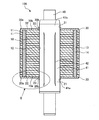
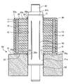
- FIG. 1 is a cross-sectional view showing a configuration of a rotor 100 of a rotary electric machine according to the present embodiment.
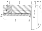
- FIG. 2 is an enlarged cross-sectional view showing part II of FIG. 1 and 2 show radial cross sections of the rotor core 10, the first end plate 20, and the second end plate 30.
- IPM Interior Permanent Magnet
- the rotor 100 shown in FIGS. 1 and 2 constitutes a part of an inner rotor type rotary electric machine.
- the inner rotor type rotary electric machine includes a rotor 100 and a stator (not shown) arranged on the outer peripheral side of the rotor 100.
- the rotor 100 is rotatably supported with respect to the stator by bearings (not shown).
- the rotor 100 includes a rotor core 10, a first end plate 20, a second end plate 30, and a shaft 40.
- the first end plate 20 is provided at one end of the rotor core 10 in the axial direction of the rotor core 10.
- the second end plate 30 is provided at the other end of the rotor core 10 in the axial direction.
- the shaft 40 penetrates each of the rotor core 10, the first end plate 20, and the second end plate 30 along the axial direction.
- the shaft 40 has a large diameter portion 41 in a part in the axial direction.
- the large diameter portion 41 has a larger diameter than the other portions of the shaft 40.
- the rotor core 10, the first end plate 20, and the second end plate 30 are fixed to the large diameter portion 41.
- the large diameter portion 41 has a first press-fitting portion 41a that is press-fitted into the first end plate 20 and a second press-fitting portion 41b that is press-fitted into the second end plate 30.
- Each of the first press-fitting portion 41a and the second press-fitting portion 41b is a part of the large diameter portion 41 in the axial direction.
- a first protrusion 42 extending in the axial direction is formed on the outer peripheral surface of the large diameter portion 41.
- the rotor core 10 has a structure in which a plurality of electromagnetic steel plates 11 are laminated.
- the rotor core 10 has a cylindrical shape as a whole.
- a through hole 12 penetrating in the axial direction is formed in the central portion of the rotor core 10.
- a large diameter portion 41 of the shaft 40 is attached to the through hole 12 of the rotor core 10 by press fitting or shrink fitting.
- the rotor core 10 is fixed to the shaft 40.
- a plurality of magnet insertion holes 13 penetrating in the axial direction are formed on the outer peripheral side of the through hole 12.
- a permanent magnet 14 is inserted into each of the magnet insertion holes 13.
- Each axial end of the magnet insertion hole 13 is closed by the first end plate 20.
- the other end of each of the magnet insertion holes 13 in the axial direction is closed by the second end plate 30.
- Each of the first end plate 20 and the second end plate 30 has a disk-like shape.
- the first end plate 20 and the second end plate 30 are formed of a non-magnetic material such as SUS304.
- the first end plate 20 and the second end plate 30 are formed of a non-magnetic material in order to prevent the magnetic flux of the permanent magnet 14 from leaking to the first end plate 20 or the second end plate 30 and lowering the magnetic force. Is.
- a first through hole 21 penetrating in the axial direction is formed in the central portion of the first end plate 20.
- the first press-fitting portion 41a of the shaft 40 is press-fitted into the first through hole 21.
- the first end plate 20 is fixed to the shaft 40.
- the first end plate 20 has a flat plate portion 22 in contact with the end surface 10a on one end side in the axial direction of the rotor core 10.
- the flat plate portion 22 has an annular shape.
- the flat plate portion 22 is provided on the outer peripheral side of the first press-fitting portion 41a of the shaft 40.
- the flat plate portion 22 is provided over the entire circumference in the circumferential direction centered on the first press-fitting portion 41a.
- the surface of the flat plate portion 22 and the end surface 10a of the rotor core 10 are in surface contact with each other without a gap.
- the outer peripheral side end portion of the flat plate portion 22, that is, the outer peripheral side end portion 20a of the first end plate 20, is located on the inner peripheral side of the outer peripheral surface of the rotor core 10 when viewed along the axial direction.
- the first end plate 20 has a warped portion 23 provided on the inner peripheral side of the flat plate portion 22 and on the outer peripheral side of the first press-fitting portion 41a of the shaft 40.
- the inner peripheral side end portion of the warped portion 23, that is, the inner peripheral side end portion 20b of the first end plate 20, is in contact with the outer peripheral surface of the first press-fitting portion 41a.
- the warped portion 23 is provided over the entire circumference in the circumferential direction centered on the first press-fitting portion 41a. In the radial cross section of the first end plate 20 as shown in FIGS.
- the warped portion 23 warps so as to be separated from the end surface 10a of the rotor core 10 as it is separated from the flat plate portion 22, that is, closer to the shaft 40. There is. Further, the warped portion 23 is continuously and smoothly connected to the flat plate portion 22 in the radial cross section, and is curved so that the rotor core 10 side is convex. The width of the warped portion 23, that is, the radial dimension of the warped portion 23 is smaller than the width of the flat plate portion 22, that is, the radial dimension of the flat plate portion 22.
- the flat plate portion 22 Since the warped portion 23 is provided, the flat plate portion 22 is pressed against the end surface 10a of the rotor core 10 by the elastic force of the first end plate 20 itself, with the inner peripheral side end portion 20b of the first end plate 20 as a fulcrum. .. Therefore, the flat plate portion 22 is in close contact with the end surface 10a of the rotor core 10 without a gap.
- a second through hole 31 penetrating in the axial direction is formed in the central portion of the second end plate 30.
- the second press-fitting portion 41b of the shaft 40 is press-fitted into the second through hole 31.
- the second end plate 30 is fixed to the shaft 40.
- the second end plate 30 has a flat plate portion 32 in contact with the end surface 10b on the other end side in the axial direction of the rotor core 10.
- the flat plate portion 32 has an annular shape.
- the flat plate portion 32 is provided on the outer peripheral side of the second press-fitting portion 41b of the shaft 40.
- the flat plate portion 32 is provided over the entire circumference in the circumferential direction centered on the second press-fitting portion 41b.
- the surface of the flat plate portion 32 and the end surface 10b of the rotor core 10 are in surface contact with each other without a gap.
- the outer peripheral side end portion of the flat plate portion 32 that is, the outer peripheral side end portion 30a of the second end plate 30, is located on the inner peripheral side of the outer peripheral surface of the rotor core 10 when viewed along the axial direction.
- the second end plate 30 has a warped portion 33 provided on the inner peripheral side of the flat plate portion 32 and on the outer peripheral side of the second press-fitting portion 41b of the shaft 40.
- the inner peripheral side end portion of the warped portion 33 that is, the inner peripheral side end portion 30b of the second end plate 30, is in contact with the outer peripheral surface of the second press-fitting portion 41b.
- the warped portion 33 is provided over the entire circumference in the circumferential direction centered on the second press-fitting portion 41b. In the radial cross section of the second end plate 30 as shown in FIG. 1, the warped portion 33 is warped so as to be separated from the end surface 10b of the rotor core 10 as it is separated from the flat plate portion 32, that is, closer to the shaft 40.
- the warped portion 33 is continuously and smoothly connected to the flat plate portion 32 in the radial cross section, and is curved so that the rotor core 10 side is convex.
- the width of the warped portion 33 that is, the radial dimension of the warped portion 33 is smaller than the width of the flat plate portion 32, that is, the radial dimension of the flat plate portion 32.
- the flat plate portion 32 Since the warped portion 33 is provided, the flat plate portion 32 is pressed against the end surface 10b of the rotor core 10 by the elastic force of the second end plate 30 itself, with the inner peripheral side end portion 30b of the second end plate 30 as a fulcrum. .. Therefore, the flat plate portion 32 is in close contact with the end surface 10b of the rotor core 10 without a gap.
- the flat plate portion 22 of the first end plate 20 is in close contact with the end surface 10a of the rotor core 10, and the flat plate portion 32 of the second end plate 30 is in close contact with the end surface 10b of the rotor core 10. That is, the rotor core 10 is pressed from both ends in the axial direction by the first end plate 20 and the second end plate 30. As a result, it is possible to prevent the electromagnetic steel sheets 11 located at both ends of the rotor core 10 in the axial direction from vibrating due to electromagnetic force during the operation of the rotary electric machine. Further, this makes it possible to regulate the axial position of the permanent magnet 14. Therefore, the noise generated during the operation of the rotary electric machine can be suppressed.
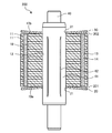
- FIG. 3 is a cross-sectional view showing the configuration of the rotor 200 of the rotary electric machine according to the comparative example of the present embodiment. Also in the configuration of the comparative example shown in FIG. 3, each of the first end plate 20 and the second end plate 30 is fixed to the shaft 40 by press fitting. However, in the configuration of the comparative example, the outer peripheral sides of the first end plate 20 and the second end plate 30 are warped in the direction away from the rotor core 10.
- a gap 201 is formed between the first end plate 20 and the end face 10a of the rotor core 10, and a gap 202 is formed between the second end plate 30 and the end face 10b of the rotor core 10.
- first end plate 20 and the second end plate 30 which were formed in a flat plate shape before press-fitting, were deformed by the stress generated during press-fitting.
- a force is locally applied around the central hole of a flat plate-shaped member such as the first end plate 20 and the second end plate 30 to press-fit the flat plate-shaped member into a columnar member such as the shaft 40, the flat plate-shaped member is formed into a flat plate.
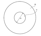
- FIG. 4 is a plan view showing the configuration of the first end plate 20 used in the method for manufacturing a rotor of a rotary electric machine according to the present embodiment.
- FIG. 4 shows the configuration of the first end plate 20 as a component before the rotor 100 is assembled.
- the first end plate 20 has a disk-like and flat plate-like shape.
- a first through hole 21 into which the first press-fitting portion 41a of the shaft 40 is press-fitted is formed in the central portion of the first end plate 20.
- the first through hole 21 has a perfect circular cross-sectional shape. That is, the inner peripheral surface of the first through hole 21 is not formed with a protrusion protruding inward in the radial direction and a concave portion recessed outward in the radial direction.
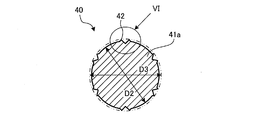
- FIG. 5 is a cross-sectional view showing the configuration of the first press-fitting portion 41a of the shaft 40 used in the method for manufacturing a rotor of a rotary electric machine according to the present embodiment.
- FIG. 5 shows a configuration in which the shaft 40 as a component before the rotor 100 is assembled is cut in a plane perpendicular to the axial direction.
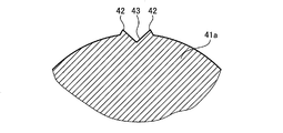
- FIG. 6 is an enlarged cross-sectional view showing the VI portion of FIG.
- first protrusions 42 projecting outward in the radial direction are formed on the outer peripheral surface of the first press-fitting portion 41a of the shaft 40, respectively.
- each of the first protrusions 42 extends along the axial direction to a portion of the large diameter portion 41 of the shaft 40 that is press-fitted into the rotor core 10.
- the first protrusion 42 has a function of securing a fixing force when the shaft 40 is press-fitted into the rotor core 10 and a function of securing a fixing force when the shaft 40 is press-fitted into the first end plate 20. ing.
- a recess 43 capable of accommodating fragments of the rotor core 10 scraped by the first protrusion 42 during press fitting is formed between two adjacent first protrusions 42.
- D1 be the diameter of the first through hole 21 of the first end plate 20 shown in FIG.
- D2 be the diameter of the cylindrical portion of the first press-fitting portion 41a in which neither the first protrusion 42 nor the recess 43 is formed.
- D3 be the diameter of the circumscribed circle that circumscribes the plurality of first protrusions 42 about the central axis of the shaft 40.
- the diameter D1, the diameter D2, and the diameter D3 satisfy the relationship of D2 ⁇ D1 ⁇ D3.
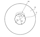
- FIG. 7 is a plan view showing the configuration of the second end plate 30 used in the method for manufacturing a rotor of a rotary electric machine according to the present embodiment.
- FIG. 7 shows the configuration of the second end plate 30 as a component before the rotor 100 is assembled.
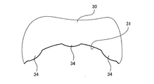
- FIG. 8 is an enlarged plan view showing the VIII portion of FIG. 7.
- the second end plate 30 has a disk-like and flat plate-like shape.
- a second through hole 31 into which the large diameter portion 41 of the shaft 40 is press-fitted is formed in the central portion of the second end plate 30.
- a plurality of second protrusions 34, each of which protrudes inward in the radial direction, are formed on the inner peripheral surface of the second through hole 31.
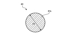
- FIG. 9 is a cross-sectional view showing the configuration of the second press-fitting portion 41b of the shaft 40 used in the method for manufacturing a rotor of a rotary electric machine according to the present embodiment.
- FIG. 9 shows a configuration in which the shaft 40 as a component before the rotor 100 is assembled is cut in a plane perpendicular to the axial direction.
- the second press-fitting portion 41b of the shaft 40 has a perfect circular cross-sectional shape. That is, the outer peripheral surface of the second press-fitting portion 41b is not formed with protrusions protruding outward in the radial direction and recesses recessed inward in the radial direction.
- the diameter of the cylindrical portion where the second protrusion 34 is not formed is defined as D4.
- D5 be the diameter of the inscribed circle inscribed in the plurality of second protrusions 34 about the central axis of the second through hole 31.
- the diameter of the second press-fitting portion 41b is D6.
- the diameter D4, the diameter D5, and the diameter D6 satisfy the relationship of D5 ⁇ D6 ⁇ D4.
- the diameter D6 of the second press-fitting portion 41b may be the same as the diameter D2 of the first press-fitting portion 41a.
- the diameter D4 of the second through hole 31 may be the same as the diameter D1 of the first through hole 21.
- the configurations of the first press-fitting portion 41a and the first end plate 20 are different from the configurations of the second press-fitting portion 41b and the second end plate 30. That is, while a plurality of first protrusions 42 are formed on the outer peripheral surface of the first press-fitting portion 41a, no protrusions or recesses are formed on the outer peripheral surface of the second press-fitting portion 41b. Further, while no protrusions or recesses are formed on the inner peripheral surface of the first through hole 21 of the first end plate 20, a plurality of protrusions and recesses are formed on the inner peripheral surface of the second through hole 31 of the second end plate 30. The second protrusion 34 is formed.
- the plurality of first protrusions 42 are not provided on the entire portion of the large diameter portion 41 to be press-fitted into the rotor core 10, and do not reach the second press-fitting portion 41b. ..
- the shaft 40 is press-fitted into the rotor core 10
- the inner peripheral surface of the rotor core 10 is scraped by the first protrusion 42.
- the scraped pieces of the rotor core 10 can be retained inside the rotor core 10.
- the configuration of the second press-fitting portion 41b and the second end plate 30 may be the same as the configuration of the first press-fitting portion 41a and the first end plate 20. That is, the first protrusion 42 is formed on the outer peripheral surface of the second press-fitting portion 41b as well as the first press-fitting portion 41a, and the second through hole 31 also has a perfect circular cross-sectional shape like the first through hole 21. You may be doing it. Alternatively, a second protrusion 34 is formed on the inner peripheral surface of the first through hole 21 as in the second through hole 31, and the first press-fitting portion 41a also has a perfect circular cross-sectional shape like the second press-fitting portion 41b. You may have.
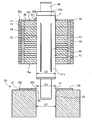
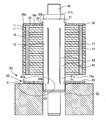
- FIGS. 10 to 13 are cross-sectional views showing a manufacturing process of the rotor 100 of the rotary electric machine according to the present embodiment.
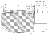
- FIG. 12 is an enlarged cross-sectional view showing the XII portion of FIG. 10 to 13 show a step of press-fitting the first press-fitting portion 41a of the shaft 40 into the first end plate 20 as a part of the manufacturing process of the rotor 100.
- the second end plate 30 is already attached to the second press-fitting portion 41b by press-fitting.
- the step of press-fitting the second press-fitting portion 41b into the second end plate 30 may be performed after the step of press-fitting the first press-fitting portion 41a into the first end plate 20.
- the step of press-fitting the second press-fitting portion 41b into the second end plate 30 can be performed in the same manner as the step of press-fitting the first press-fitting portion 41a into the first end plate 20.
- FIG. 10 shows a state before the shaft 40 is press-fitted into the first end plate 20.
- the flat plate-shaped first end plate 20 is first supported by the jig 50.
- the jig 50 has a flat surface portion 51 that supports the first end plate 20, and a cylindrical hole portion 52 that is formed at a position surrounded by the flat surface portion 51 and extends in a direction perpendicular to the flat surface portion 51. ing. Assuming that the diameter of the hole 52 is D7, the diameter D7 satisfies the relationship of D7> D1 and the relationship of D7> D2.
- a tapered surface 53 is formed on the entire circumference of the corner portion between the flat surface portion 51 and the inner peripheral surface of the hole portion 52.
- the first end plate 20 is positioned so that the center of the hole 52 and the center of the first through hole 21 coincide with each other when viewed in a direction perpendicular to the flat surface 51.
- FIGS. 11 and 12 show a state in which the shaft 40 is being press-fitted into the first end plate 20.
- the first press-fitting portion 41a of the shaft 40 is gradually press-fitted into the first through hole 21 of the first end plate 20.
- the inner peripheral side end portion 20b of the first end plate 20 is deformed by the stress generated by the press fitting of the shaft 40. That is, the inner peripheral side end portion 20b of the first end plate 20 is deformed along the tapered surface 53 with the inner peripheral edge portion 51a of the flat surface portion 51 as a fulcrum.
- the inner peripheral side end portion 20b of the first end plate 20 is warped in the press-fitting direction of the shaft 40.
- the warped portion 23 is formed on the inner peripheral side of the first end plate 20.
- the outer peripheral side end portion 20a of the first end plate 20 rises from the flat surface portion 51 with the inner peripheral edge portion 51a as a fulcrum.
- a gap 54 is formed between the outer peripheral side end portion 20a and the flat surface portion 51.
- the first end plate 20 is deformed into a disc spring-like shape that is convex in the direction away from the rotor core 10 as a whole.
- FIG. 13 shows a state in which the press-fitting of the shaft 40 into the first end plate 20 is completed.
- the portion of the first end plate 20 on the outer peripheral side of the warped portion 23 is sandwiched between the end surface 10a of the rotor core 10 and the flat surface portion 51 of the jig 50 and deformed into a flat plate shape. ..
- the flat plate portion 22 is formed on the first end plate 20.
- the flat plate portion 22 is pressed against the end face 10b of the rotor core 10 by the elastic force of the first end plate 20 itself, with the inner peripheral side end portion 20b as a fulcrum.
- the flat plate portion 22 is in close contact with the end surface 10a of the rotor core 10 without a gap.
- the elastic force of the first end plate 20 is obtained by deforming the first end plate 20 itself into a disc spring-like shape with the press fitting of the shaft 40.
- the reason why the first end plate 20 is deformed into a disc spring-like shape is mainly due to the action of the tapered surface 53 provided on the jig 50.
- each of the first end plate 20 and the second end plate 30 is brought into close contact with the rotor core 10 by its own elastic force without any gap.
- flat plate-shaped parts can be used for each of the first end plate 20 and the second end plate 30, and it is not necessary to add other parts such as rivets and bosses. Therefore, it is possible to simplify the manufacturing process of the rotor 100 and reduce the manufacturing cost of the rotor 100.
- the rotor 100 of the rotary electric machine includes a rotor core 10, a first end plate 20, and a shaft 40.
- the first end plate 20 is provided at the end of the rotor core 10 in the axial direction of the rotor core 10.
- the shaft 40 penetrates each of the rotor core 10 and the first end plate 20 along the axial direction.
- the first end plate 20 has an annular flat plate portion 22 in contact with the rotor core 10 and a warped portion 23 provided on the inner peripheral side of the flat plate portion 22 and in contact with the shaft 40. In the radial cross section of the first end plate 20, the warped portion 23 is warped so as to be separated from the rotor core 10 as the distance from the flat plate portion 22 increases.
- the first end plate 20 is an example of an end plate.
- the flat plate portion 22 of the first end plate 20 is pressed against the rotor core 10 by the elastic force of the first end plate 20 itself. Therefore, according to the above configuration, the first end plate 20 and the rotor core 10 can be brought into close contact with each other more reliably.
- the first press-fitting portion 41a located on one end side of the rotor core 10 in the shaft 40 to which the rotor core 10 is attached is supported by a jig 50 in a flat plate shape. It has a step of press-fitting into the first through hole 21 of the first end plate 20.
- the jig 50 has a flat surface portion 51, a hole portion 52, and a tapered surface 53. The flat surface portion 51 is configured to support the first end plate 20.
- the hole portion 52 is formed at a position surrounded by the flat surface portion 51, has a diameter D7 larger than both the diameter D1 of the first through hole 21 and the diameter D2 of the first press-fitting portion 41a, and is perpendicular to the flat surface portion 51. It is stretched in the above direction.
- the tapered surface 53 is formed between the inner peripheral surface of the hole 52 and the flat surface 51.
- the inner peripheral side end portion of the first end plate 20 is deformed along the tapered surface 53.
- the first end plate 20 is deformed into a disc spring-like shape as a whole.
- the first protrusion 42 is formed on the outer peripheral surface of the first press-fitting portion 41a, and the first through hole 21 is formed in a perfect circular cross section. Has been done. According to this configuration, the fixing force between the first end plate 20 and the shaft 40 can be secured by the first protrusion 42.
- the first press-fitting portion 41a is formed in a perfect circular cross section, and the second protrusion 34 is provided on the inner peripheral surface of the first through hole 21. It is formed. According to this configuration, the fixing force between the first end plate 20 and the shaft 40 can be secured by the second protrusion 34.
- the second press-fitting portion 41b located on the other end side of the rotor core 10 in the shaft 40 is supported by the jig 50 at the second flat end. It further includes a step of press-fitting into the second through hole 31 of the plate 30.
- a first protrusion 42 is formed on the outer peripheral surface of the first press-fitting portion 41a.
- the first through hole 21 is formed to have a perfect circular cross section.
- the second press-fitting portion 41b is formed to have a perfect circular cross section.
- a second protrusion 34 is formed on the inner peripheral surface of the second through hole 31.
- the present invention is not limited to the above embodiment and can be modified in various ways.
- the IPM type rotor 100 is taken as an example, but the present invention can be applied to various types of rotors such as SPM (Surface Permanent Magnet) type, sequential type, and inset type. ..
Landscapes
- Engineering & Computer Science (AREA)
- Power Engineering (AREA)
- Manufacturing & Machinery (AREA)
- Iron Core Of Rotating Electric Machines (AREA)
- Manufacture Of Motors, Generators (AREA)
Abstract
Description
本発明に係る回転電機のロータの製造方法は、ロータコアが取り付けられたシャフトにおいて前記ロータコアの一端側に位置する第1圧入部を、治具に支持された平板状の第1端板の第1貫通孔に圧入する工程を有し、前記治具は、前記第1端板を支持する平面部と、前記平面部に囲まれた位置に形成され、前記第1貫通孔の直径及び前記第1圧入部の直径のいずれよりも大きい直径を有し、前記平面部と垂直な方向に延伸した穴部と、前記穴部の内周面と前記平面部との間に形成されたテーパ面と、を有している。
本発明の実施の形態1に係る回転電機のロータ及びその製造方法について説明する。まず、本実施の形態に係る回転電機のロータの構成について図1及び図2を用いて説明する。図1は、本実施の形態に係る回転電機のロータ100の構成を示す断面図である。図2は、図1のII部を拡大して示す断面図である。図1及び図2では、ロータコア10、第1端板20及び第2端板30の径方向断面が示されている。本実施の形態では、永久磁石14が内部に埋め込まれたIPM(Interior Permanent Magnet)方式のロータ100を例示している。
Claims (5)
- ロータコアと、
前記ロータコアの軸方向において前記ロータコアの端部に設けられた端板と、
前記ロータコア及び前記端板のそれぞれを前記軸方向に沿って貫通したシャフトと、
を備え、
前記端板は、前記ロータコアに接触した環状の平板部と、前記平板部よりも内周側に設けられ前記シャフトに接触した反り部と、を有しており、
前記反り部は、前記端板の径方向断面において、前記平板部から離れるほど前記ロータコアから離れるように反っている回転電機のロータ。 - ロータコアが取り付けられたシャフトにおいて前記ロータコアの一端側に位置する第1圧入部を、治具に支持された平板状の第1端板の第1貫通孔に圧入する工程を有し、
前記治具は、
前記第1端板を支持する平面部と、
前記平面部に囲まれた位置に形成され、前記第1貫通孔の直径及び前記第1圧入部の直径のいずれよりも大きい直径を有し、前記平面部と垂直な方向に延伸した穴部と、
前記穴部の内周面と前記平面部との間に形成されたテーパ面と、
を有している回転電機のロータの製造方法。 - 前記第1圧入部の外周面には第1突起が形成されており、
前記第1貫通孔は断面真円状に形成されている請求項2に記載の回転電機のロータの製造方法。 - 前記第1圧入部は断面真円状に形成されており、
前記第1貫通孔の内周面には第2突起が形成されている請求項2に記載の回転電機のロータの製造方法。 - 前記シャフトにおいて前記ロータコアの他端側に位置する第2圧入部を、前記治具に支持された平板状の第2端板の第2貫通孔に圧入する工程をさらに有し、
前記第1圧入部の外周面には第1突起が形成されており、
前記第1貫通孔は断面真円状に形成されており、
前記第2圧入部は断面真円状に形成されており、
前記第2貫通孔の内周面には第2突起が形成されている請求項2に記載の回転電機のロータの製造方法。
Priority Applications (5)
| Application Number | Priority Date | Filing Date | Title |
|---|---|---|---|
| PCT/JP2019/027569 WO2021005794A1 (ja) | 2019-07-11 | 2019-07-11 | 回転電機のロータ及びその製造方法 |
| JP2021530462A JP7123261B2 (ja) | 2019-07-11 | 2019-07-11 | 回転電機のロータ及びその製造方法 |
| US17/600,397 US12040665B2 (en) | 2019-07-11 | 2019-07-11 | Rotor of rotating electric machine and method of manufacturing rotor |
| EP19936996.8A EP3998695A4 (en) | 2019-07-11 | 2019-07-11 | ROTOR FOR ELECTRIC ROTATING MACHINE AND METHOD FOR MANUFACTURING THEREOF |
| CN201980098219.0A CN114128090B (zh) | 2019-07-11 | 2019-07-11 | 旋转电机的转子及其制造方法 |
Applications Claiming Priority (1)
| Application Number | Priority Date | Filing Date | Title |
|---|---|---|---|
| PCT/JP2019/027569 WO2021005794A1 (ja) | 2019-07-11 | 2019-07-11 | 回転電機のロータ及びその製造方法 |
Publications (1)
| Publication Number | Publication Date |
|---|---|
| WO2021005794A1 true WO2021005794A1 (ja) | 2021-01-14 |
Family
ID=74114501
Family Applications (1)
| Application Number | Title | Priority Date | Filing Date |
|---|---|---|---|
| PCT/JP2019/027569 Ceased WO2021005794A1 (ja) | 2019-07-11 | 2019-07-11 | 回転電機のロータ及びその製造方法 |
Country Status (5)
| Country | Link |
|---|---|
| US (1) | US12040665B2 (ja) |
| EP (1) | EP3998695A4 (ja) |
| JP (1) | JP7123261B2 (ja) |
| CN (1) | CN114128090B (ja) |
| WO (1) | WO2021005794A1 (ja) |
Cited By (1)
| Publication number | Priority date | Publication date | Assignee | Title |
|---|---|---|---|---|
| JP7204027B1 (ja) | 2022-04-25 | 2023-01-13 | 三菱電機株式会社 | 回転電機及びそのローター |
Families Citing this family (2)
| Publication number | Priority date | Publication date | Assignee | Title |
|---|---|---|---|---|
| US11742711B1 (en) * | 2019-11-19 | 2023-08-29 | United States Of America As Represented By The Secretary Of The Air Force | Rotor for a high speed electrical machine |
| JP7740944B2 (ja) * | 2021-09-29 | 2025-09-17 | ニデック株式会社 | ロータ及びモータ |
Citations (4)
| Publication number | Priority date | Publication date | Assignee | Title |
|---|---|---|---|---|
| JP2005295744A (ja) * | 2004-04-02 | 2005-10-20 | Nissan Motor Co Ltd | 回転電機用ロータの製造方法および回転電機用ロータ |
| JP2008178253A (ja) * | 2007-01-19 | 2008-07-31 | Fanuc Ltd | 電動機ロータの製造方法及び電動機 |
| JP2016201896A (ja) * | 2015-04-09 | 2016-12-01 | トヨタ自動車株式会社 | ロータ及びその製造方法 |
| JP2018182795A (ja) * | 2017-04-04 | 2018-11-15 | 日産自動車株式会社 | 電動モータのロータ製造方法及び電動モータのロータ |
Family Cites Families (10)
| Publication number | Priority date | Publication date | Assignee | Title |
|---|---|---|---|---|
| JP2005130688A (ja) * | 2003-10-01 | 2005-05-19 | Asmo Co Ltd | 磁石埋込型ロータ、及び電動機 |
| JP2005229767A (ja) | 2004-02-16 | 2005-08-25 | Mitsubishi Electric Corp | 回転電機 |
| JP2007329986A (ja) * | 2006-06-06 | 2007-12-20 | Toshiba Mitsubishi-Electric Industrial System Corp | 回転電機の回転子 |
| JP5500360B2 (ja) * | 2010-05-12 | 2014-05-21 | 株式会社デンソー | 回転電機の回転子 |
| JP5560917B2 (ja) * | 2010-06-03 | 2014-07-30 | トヨタ自動車株式会社 | 回転電機用ロータの製造方法及び回転電機用シャフト素材 |
| JP5141749B2 (ja) * | 2010-12-06 | 2013-02-13 | トヨタ自動車株式会社 | エンドプレートおよびこれを用いた回転電機のロータ |
| US8970085B2 (en) * | 2011-04-01 | 2015-03-03 | Denso Corporation | Rotor for electric rotating machine and method of manufacturing the same |
| JP5685506B2 (ja) * | 2011-08-19 | 2015-03-18 | 株式会社安川電機 | 回転電機の回転子、回転電機および回転子の端面部材 |
| JP2017184375A (ja) * | 2016-03-29 | 2017-10-05 | トヨタ自動車株式会社 | 回転電機のロータ |
| JP6804633B2 (ja) * | 2017-03-28 | 2020-12-23 | 本田技研工業株式会社 | ロータ |
-
2019
- 2019-07-11 JP JP2021530462A patent/JP7123261B2/ja active Active
- 2019-07-11 US US17/600,397 patent/US12040665B2/en active Active
- 2019-07-11 WO PCT/JP2019/027569 patent/WO2021005794A1/ja not_active Ceased
- 2019-07-11 EP EP19936996.8A patent/EP3998695A4/en active Pending
- 2019-07-11 CN CN201980098219.0A patent/CN114128090B/zh active Active
Patent Citations (4)
| Publication number | Priority date | Publication date | Assignee | Title |
|---|---|---|---|---|
| JP2005295744A (ja) * | 2004-04-02 | 2005-10-20 | Nissan Motor Co Ltd | 回転電機用ロータの製造方法および回転電機用ロータ |
| JP2008178253A (ja) * | 2007-01-19 | 2008-07-31 | Fanuc Ltd | 電動機ロータの製造方法及び電動機 |
| JP2016201896A (ja) * | 2015-04-09 | 2016-12-01 | トヨタ自動車株式会社 | ロータ及びその製造方法 |
| JP2018182795A (ja) * | 2017-04-04 | 2018-11-15 | 日産自動車株式会社 | 電動モータのロータ製造方法及び電動モータのロータ |
Non-Patent Citations (1)
| Title |
|---|
| See also references of EP3998695A4 * |
Cited By (2)
| Publication number | Priority date | Publication date | Assignee | Title |
|---|---|---|---|---|
| JP7204027B1 (ja) | 2022-04-25 | 2023-01-13 | 三菱電機株式会社 | 回転電機及びそのローター |
| JP2023161169A (ja) * | 2022-04-25 | 2023-11-07 | 三菱電機株式会社 | 回転電機及びそのローター |
Also Published As
| Publication number | Publication date |
|---|---|
| JP7123261B2 (ja) | 2022-08-22 |
| EP3998695A4 (en) | 2022-07-20 |
| EP3998695A1 (en) | 2022-05-18 |
| JPWO2021005794A1 (ja) | 2021-11-18 |
| CN114128090B (zh) | 2025-06-10 |
| CN114128090A (zh) | 2022-03-01 |
| US12040665B2 (en) | 2024-07-16 |
| US20220216774A1 (en) | 2022-07-07 |
Similar Documents
| Publication | Publication Date | Title |
|---|---|---|
| CN103004056B (zh) | 旋转电机用转子芯及其制造方法 | |
| CN107408852B (zh) | 转子、旋转电机以及转子的制造方法 | |
| CN101621221B (zh) | 电动机及该电动机的制造方法 | |
| CN103051087B (zh) | 旋转电机的转子 | |
| US20140062245A1 (en) | Rotor for rotating electric machine | |
| EP3018802B1 (en) | Method for producing a rotor | |
| JP7123261B2 (ja) | 回転電機のロータ及びその製造方法 | |
| JP7132857B2 (ja) | 永久磁石埋設型ロータ及び永久磁石埋設型ロータの製造方法 | |
| WO2009093524A1 (ja) | 回転子積層鉄心 | |
| JP2000341920A (ja) | 永久磁石埋め込み型モータ | |
| JP2011135634A (ja) | ステータおよびこのステータを備えるモータ | |
| WO2014184842A1 (ja) | 回転電機の磁石埋込型ロータ | |
| JP2005137117A (ja) | 回転電機の回転子 | |
| JP2010136514A (ja) | ロータ | |
| JP2013143805A (ja) | 回転電機のロータ、およびこれを備えた回転電機 | |
| JPH05219668A (ja) | 永久磁石式回転子 | |
| JP2005323429A (ja) | 回転電機及びその組立て方法 | |
| JP7378496B2 (ja) | 回転電機のロータおよび回転電機のロータの製造方法 | |
| WO2020017189A1 (ja) | モータおよびモータの製造方法 | |
| JP2024093453A (ja) | ロータ、回転電機、およびロータの製造方法 | |
| CN116722683A (zh) | 旋转电机的转子 | |
| JP2007037288A (ja) | 永久磁石形回転電機用回転子及びその製造方法 | |
| JP2020156164A (ja) | ロータおよびロータの製造方法 | |
| JP2019221035A (ja) | 回転電機および回転電機の製造方法 | |
| JP2018125986A (ja) | 回転電機のステータ |
Legal Events
| Date | Code | Title | Description |
|---|---|---|---|
| 121 | Ep: the epo has been informed by wipo that ep was designated in this application |
Ref document number: 19936996 Country of ref document: EP Kind code of ref document: A1 |
|
| ENP | Entry into the national phase |
Ref document number: 2021530462 Country of ref document: JP Kind code of ref document: A |
|
| NENP | Non-entry into the national phase |
Ref country code: DE |
|
| ENP | Entry into the national phase |
Ref document number: 2019936996 Country of ref document: EP Effective date: 20220211 |
|
| WWG | Wipo information: grant in national office |
Ref document number: 201980098219.0 Country of ref document: CN |