WO2021005974A1 - 車載ネットワークシステム - Google Patents
車載ネットワークシステム Download PDFInfo
- Publication number
- WO2021005974A1 WO2021005974A1 PCT/JP2020/023404 JP2020023404W WO2021005974A1 WO 2021005974 A1 WO2021005974 A1 WO 2021005974A1 JP 2020023404 W JP2020023404 W JP 2020023404W WO 2021005974 A1 WO2021005974 A1 WO 2021005974A1
- Authority
- WO
- WIPO (PCT)
- Prior art keywords
- power supply
- power
- electronic device
- hub
- vehicle
- Prior art date
- Legal status (The legal status is an assumption and is not a legal conclusion. Google has not performed a legal analysis and makes no representation as to the accuracy of the status listed.)
- Ceased
Links
Images


Classifications
-
- H—ELECTRICITY
- H02—GENERATION; CONVERSION OR DISTRIBUTION OF ELECTRIC POWER
- H02J—ELECTRIC POWER NETWORKS; CIRCUIT ARRANGEMENTS OR SYSTEMS FOR SUPPLYING OR DISTRIBUTING ELECTRIC POWER; SYSTEMS FOR STORING ELECTRIC ENERGY
- H02J1/00—Circuit arrangements for DC mains or DC distribution networks
- H02J1/14—Balancing load and power generation in DC networks
-
- H—ELECTRICITY
- H02—GENERATION; CONVERSION OR DISTRIBUTION OF ELECTRIC POWER
- H02J—ELECTRIC POWER NETWORKS; CIRCUIT ARRANGEMENTS OR SYSTEMS FOR SUPPLYING OR DISTRIBUTING ELECTRIC POWER; SYSTEMS FOR STORING ELECTRIC ENERGY
- H02J7/00—Circuit arrangements for charging or discharging batteries or for supplying loads from batteries
- H02J7/855—Circuit arrangements for charging or discharging batteries or for supplying loads from batteries with circuits adapted for supplying loads from the battery
-
- B—PERFORMING OPERATIONS; TRANSPORTING
- B60—VEHICLES IN GENERAL
- B60R—VEHICLES, VEHICLE FITTINGS, OR VEHICLE PARTS, NOT OTHERWISE PROVIDED FOR
- B60R16/00—Electric or fluid circuits specially adapted for vehicles and not otherwise provided for; Arrangement of elements of electric or fluid circuits specially adapted for vehicles and not otherwise provided for
- B60R16/02—Electric or fluid circuits specially adapted for vehicles and not otherwise provided for; Arrangement of elements of electric or fluid circuits specially adapted for vehicles and not otherwise provided for electric constitutive elements
- B60R16/0207—Wire harnesses
- B60R16/0215—Protecting, fastening and routing means therefor
-
- B—PERFORMING OPERATIONS; TRANSPORTING
- B60—VEHICLES IN GENERAL
- B60R—VEHICLES, VEHICLE FITTINGS, OR VEHICLE PARTS, NOT OTHERWISE PROVIDED FOR
- B60R16/00—Electric or fluid circuits specially adapted for vehicles and not otherwise provided for; Arrangement of elements of electric or fluid circuits specially adapted for vehicles and not otherwise provided for
- B60R16/02—Electric or fluid circuits specially adapted for vehicles and not otherwise provided for; Arrangement of elements of electric or fluid circuits specially adapted for vehicles and not otherwise provided for electric constitutive elements
- B60R16/023—Electric or fluid circuits specially adapted for vehicles and not otherwise provided for; Arrangement of elements of electric or fluid circuits specially adapted for vehicles and not otherwise provided for electric constitutive elements for transmission of signals between vehicle parts or subsystems
- B60R16/0238—Electrical distribution centers
-
- B—PERFORMING OPERATIONS; TRANSPORTING
- B60—VEHICLES IN GENERAL
- B60R—VEHICLES, VEHICLE FITTINGS, OR VEHICLE PARTS, NOT OTHERWISE PROVIDED FOR
- B60R16/00—Electric or fluid circuits specially adapted for vehicles and not otherwise provided for; Arrangement of elements of electric or fluid circuits specially adapted for vehicles and not otherwise provided for
- B60R16/02—Electric or fluid circuits specially adapted for vehicles and not otherwise provided for; Arrangement of elements of electric or fluid circuits specially adapted for vehicles and not otherwise provided for electric constitutive elements
- B60R16/03—Electric or fluid circuits specially adapted for vehicles and not otherwise provided for; Arrangement of elements of electric or fluid circuits specially adapted for vehicles and not otherwise provided for electric constitutive elements for supply of electrical power to vehicle subsystems or for
- B60R16/033—Electric or fluid circuits specially adapted for vehicles and not otherwise provided for; Arrangement of elements of electric or fluid circuits specially adapted for vehicles and not otherwise provided for electric constitutive elements for supply of electrical power to vehicle subsystems or for characterised by the use of electrical cells or batteries
-
- H—ELECTRICITY
- H02—GENERATION; CONVERSION OR DISTRIBUTION OF ELECTRIC POWER
- H02J—ELECTRIC POWER NETWORKS; CIRCUIT ARRANGEMENTS OR SYSTEMS FOR SUPPLYING OR DISTRIBUTING ELECTRIC POWER; SYSTEMS FOR STORING ELECTRIC ENERGY
- H02J1/00—Circuit arrangements for DC mains or DC distribution networks
-
- H—ELECTRICITY
- H02—GENERATION; CONVERSION OR DISTRIBUTION OF ELECTRIC POWER
- H02J—ELECTRIC POWER NETWORKS; CIRCUIT ARRANGEMENTS OR SYSTEMS FOR SUPPLYING OR DISTRIBUTING ELECTRIC POWER; SYSTEMS FOR STORING ELECTRIC ENERGY
- H02J1/00—Circuit arrangements for DC mains or DC distribution networks
- H02J1/08—Three-wire DC power distribution systems; Systems having more than three wires
- H02J1/084—Three-wire DC power distribution systems; Systems having more than three wires for selectively connecting the load or loads to one or several among a plurality of power lines or power sources
-
- H—ELECTRICITY
- H02—GENERATION; CONVERSION OR DISTRIBUTION OF ELECTRIC POWER
- H02J—ELECTRIC POWER NETWORKS; CIRCUIT ARRANGEMENTS OR SYSTEMS FOR SUPPLYING OR DISTRIBUTING ELECTRIC POWER; SYSTEMS FOR STORING ELECTRIC ENERGY
- H02J7/00—Circuit arrangements for charging or discharging batteries or for supplying loads from batteries
- H02J7/34—Parallel operation in networks using both storage and other DC sources, e.g. providing buffering
-
- H—ELECTRICITY
- H02—GENERATION; CONVERSION OR DISTRIBUTION OF ELECTRIC POWER
- H02J—ELECTRIC POWER NETWORKS; CIRCUIT ARRANGEMENTS OR SYSTEMS FOR SUPPLYING OR DISTRIBUTING ELECTRIC POWER; SYSTEMS FOR STORING ELECTRIC ENERGY
- H02J2105/00—Networks for supplying or distributing electric power characterised by their spatial reach or by the load
- H02J2105/30—Networks for supplying or distributing electric power characterised by their spatial reach or by the load the load networks being external to vehicles, i.e. exchanging power with vehicles
-
- Y—GENERAL TAGGING OF NEW TECHNOLOGICAL DEVELOPMENTS; GENERAL TAGGING OF CROSS-SECTIONAL TECHNOLOGIES SPANNING OVER SEVERAL SECTIONS OF THE IPC; TECHNICAL SUBJECTS COVERED BY FORMER USPC CROSS-REFERENCE ART COLLECTIONS [XRACs] AND DIGESTS
- Y02—TECHNOLOGIES OR APPLICATIONS FOR MITIGATION OR ADAPTATION AGAINST CLIMATE CHANGE
- Y02T—CLIMATE CHANGE MITIGATION TECHNOLOGIES RELATED TO TRANSPORTATION
- Y02T10/00—Road transport of goods or passengers
- Y02T10/80—Technologies aiming to reduce greenhouse gasses emissions common to all road transportation technologies
- Y02T10/92—Energy efficient charging or discharging systems for batteries, ultracapacitors, supercapacitors or double-layer capacitors specially adapted for vehicles
Definitions
- the technology disclosed here belongs to the technical field related to in-vehicle network systems.
- Patent Document 1 a gateway ECU that relays communication between ECUs of different networks is provided, and only a network in which a transmission target ECU that first starts transmission after all networks go to sleep is waked up.
- An in-vehicle communication system is disclosed.
- Patent Document 1 since the unused ECU is waked up in the network including the transmission target ECU, wasteful power consumption may occur. Therefore, there is room for improvement from the viewpoint of reducing power consumption.
- the technology disclosed here was made in view of these points, and the purpose of the technology is to simplify the configuration of the power supply system of the vehicle and suppress the increase in power consumption.
- the technology disclosed herein targets an in-vehicle network system of a vehicle having a plurality of electronic devices operated by electric power supplied from the battery, and supplies a power source between the battery and each of the electronic devices.
- a plurality of power hubs arranged in the middle of the path and connected to a part of each of the electronic devices by a power supply line, and power supply / cutoff to each of the connected electronic devices provided in each of the power hubs.
- Each of the electronic devices is provided with a plurality of power supply ICs for performing the above and a plurality of power supply control units for outputting control signals relating to supply / cutoff of power to each electronic device to each of the power supply ICs.
- Each power hub includes a first electronic device capable of constantly supplying power from the battery and a second electronic device capable of supplying power from the battery by the operation of a occupant of the vehicle.
- Each of the first and second electronic devices is connected to the battery or another power hub by one main power supply line, and the first and second electronic devices are connected to the power hub located in the vicinity, respectively, and the respective power control devices.
- Is configured to output a control signal to each power supply IC in order to distribute the power supplied to each power supply hub by each main power supply line to the first and second electronic devices.
- the power hub is connected to the battery or another power hub by one main feeder.
- the first and second electronic devices are connected to power hubs located in the vicinity, respectively.
- the length of the feeder line extending from the first and second electronic devices to the power supply hub can be shortened as much as possible.
- the configuration of the power supply system can be simplified. Further, by shortening the feeding line, the power consumption due to the electric resistance of the feeding line can be reduced as much as possible.
- the power supply control unit can switch the supply / cutoff of power to the first and second electronic devices for each power hub. That is, since each power hub itself is connected to a battery or another power hub, the first electronic device can always be in a state where power can be supplied. On the other hand, the supply / cutoff of electric power to the second electronic device can be switched by software via the power supply control unit and the power supply hub. As a result, it is possible to supply power only to the electronic devices that require power supply among the first and second electronic devices. As a result, power consumption can also be reduced.
- a central processing unit for setting the electronic device to be operated according to the scene of the vehicle is further provided, and each power supply control unit is built in each power supply hub and the central processing unit is installed. It may be configured to receive the signal from the device and generate the control signal to be output to the corresponding power supply IC.
- each power supply control unit is built in each power supply hub, the configuration of the power supply system can be further simplified.
- the second electronic devices having a common unused scene among the second electronic devices located in the vicinity of the respective power hubs are collectively supplied with the power supply by a single power supply line. It may be configured to be connected to a hub.
- the number of feeders can be reduced by connecting to the power hub with a single feeder.
- control can be simplified by cutting off the power supply at the same time.
- each of the first electronic devices may be connected to the corresponding power supply hub by an independent feeder line.
- the first electronic device that operates by being constantly supplied with power does not need to be operated in particular when the occupant is on board, such as a keyless device or a surveillance camera for preventing theft. Includes things. Therefore, by connecting each of the first electronic devices to the power supply hub by an individual feeder, it is possible to appropriately cut off the power supply for the electronic devices that do not need to be constantly operated. As a result, the increase in power consumption can be suppressed more effectively.
- the power hub is located near the first electronic device and is connected to the battery or other power hub.
- the first and second electronic devices are connected to power hubs located in the vicinity, respectively.
- the power supply control unit can switch the supply / cutoff of power to the first and second electronic devices by software. As a result, power consumption can be reduced.
- FIG. It is a block diagram which shows the power system of the vehicle which mounted the vehicle-mounted network which concerns on Embodiment 1.
- FIG. It is a block diagram which shows an example of the power supply topology of a zone near the side door on the left front side. It is a table showing an example of an electronic device that is not used for each scene. It is a block diagram which shows an example of the power supply topology of the zone of the vehicle left front of the vehicle which mounted the vehicle-mounted network which concerns on Embodiment 2.
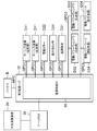
- FIG. 1 shows a power supply system of a vehicle 1 equipped with an in-vehicle network according to the first embodiment.
- the vehicle 1 is a 5-door type vehicle having four side doors and one back door.
- the vehicle 1 has a plurality of electronic devices D that are operated by the electric power supplied from the battery B.
- Each electronic device D includes an electronic device (first electronic device) that can always supply power from the battery and an electronic device (second electronic device) that can supply power from the battery B by the operation of the occupant of the vehicle 1. Equipment) and including.
- an electronic device capable of constantly supplying power from a battery is referred to as a constant power supply electronic device D1.
- an electronic device capable of supplying power from the battery B by the operation of an occupant of the vehicle 1 and having relatively low power consumption is referred to as an accessory electronic device D2.
- an electronic device capable of supplying power from the battery B by the operation of an occupant of the vehicle 1 and having a relatively large power consumption is referred to as an ignition electronic device D3.
- the electronic device belonging to the constant power supply electronic device D1 is indicated as the electronic device D1n (n is 1, 2, 7), And the electronic device belonging to the accessory electronic device D2 is D2n (n is 1, 2, ). 7), And the electronic device belonging to the ignition electronic device D3 may be indicated as D3n (n is 1, 2, ).
- the electronic devices D1 to D3 are not distinguished, they are simply referred to as electronic devices D.
- the constant power supply electronic device D1 is, for example, a keyless device D11, a surveillance camera device D12 for theft monitoring, a burglar alarm device D13, a brake light D14, and the like.
- the accessory electronic device D2 is an electronic device that is supposed to be used regardless of whether the engine of the vehicle 1 is turned on or off, and is, for example, a headlight D21, an electric mirror D22, an audio device D23, or the like.
- the ignition electronic device D3 can be used even when the engine of the vehicle 1 is off, but is basically an electronic device that is supposed to be used when the engine is on.
- the electronic device D is a concept including a sensor for operating each of the devices, an actuator, an ECU for controlling the actuator, and the like.
- the vehicle 1 is divided into a plurality of zones (six in the first embodiment), and the on / off of the power supply of the electronic device D can be controlled for each zone.
- the power hub 10 referred to here has a function of dividing the power supplied from the battery B for each power system (constant power supply, accessory power supply, and ignition power supply) at a position close to each electronic device D and distributing the power to each electronic device.
- the power supply hub 10 arranged on the left front side is referred to as a first power supply hub 11, and the power supply hub 10 arranged near the side door zone on the left front side is referred to as a second power supply hub 12 on the left rear side.
- the arranged power supply hub 10 is referred to as a third power supply hub 13, the power supply hub 10 arranged on the right front side is referred to as a fourth power supply hub 14, and the power supply hub 10 arranged near the side door on the right front side is referred to as a fifth power supply. It is called a hub 15, and the power supply hub 10 arranged on the right rear side is sometimes called a sixth power supply hub 16.
- the power hubs 11 to 16 are not distinguished, they are simply referred to as power hubs 10.
- the number of zones is increased or decreased, the number of power supply hubs 10 is also increased or decreased accordingly.
- Each power hub 10 is arranged in the middle of the power path between the battery B and each electronic device D.
- Each power hub 10 is connected to the battery B or a nearby power hub 10 by a single main feeder MPC.
- the first power supply hub 11 and the fourth power supply hub 14 are connected to the battery B by the main feeder line MPC.
- the second power supply hub 12 is connected to the first power supply hub 11 by the main feeder line MPC.
- the third power supply hub 13 is connected to the second power supply hub 12 by the main feeder line MPC.
- the fifth power supply hub 15 is connected to the fourth power supply hub 14 by the main feeder line MPC.
- the sixth power supply hub 16 is connected to the fifth power supply hub 15 by a main feeder line MPC. Further, the third power supply hub 13 and the sixth power supply hub 16 are connected to each other by the main feeder line MPC.
- the battery B and the power supply hubs 11 to 16 form a loop-shaped power supply path.
- the power hubs 11 to 16 are basically supplied with power from the battery B through the shorter power path, but when a part of the main feeder line MPC is disconnected, other power hubs 11 to 16 are basically supplied. Power is supplied through the power path.
- the second power supply hub 12 is basically supplied with electric power from the battery B via the first power supply hub 11.
- the fourth power supply hub 14, the fifth power supply hub 15, the sixth power supply hub 16, and the third power supply hub 13 are disconnected. Power is supplied from the battery B via.
- Each power hub 10 is arranged in the vicinity of the constant power supply electronic device D1 in the vehicle 10.
- Each power hub 10 is connected to the constant power supply electronic device D1, the accessory electronic device D2, and the ignition electronic device D3 located in the vicinity by feeding lines SPC1 to 3, respectively.
- Each main feeder line MPC and each feeder line SPC may be any electric wire that can supply electric power, and is composed of, for example, a wire harness.
- each power hub 10 has a plurality of power supply ICs 50 (see FIG. 2) for supplying / cutting power to each connected electronic device D.
- Each power hub 10 is connected to the zone ECU 20.
- Each zone ECU 20 is configured to input a control signal from a central processing unit 30 that controls the entire control of the vehicle 1.
- the central processing unit 30 and each zone ECU 20 are connected by communication wiring.
- the central processing unit 30 sets the electronic device D to be operated according to the scene of the vehicle 1.
- Each zone ECU 20 receives a control signal from the central processing unit 30, and receives a control signal for supplying / cutting power to each electronic device D to each power hub 10 (strictly speaking, a power supply IC described later). Is output respectively.
- each zone ECU 20 has a function of managing and controlling each electronic device D.
- the zone ECU 20 receives detection results from various sensors (vehicle speed sensor, vehicle interior temperature sensor, etc.) and uses them for processing in the own machine or transmits information to the central processing unit 30.
- FIG. 2 shows an example of the power supply topology of the zone near the side door on the left front side, that is, the zone in which the second power supply hub 12 is arranged.
- the second power hub 12 includes a left front side door locking mechanism in the keyless device D11, a left rear side door locking mechanism in the keyless device D11, a left electric mirror D22, and an indoor use.
- Camera D24, air conditioner D31, electric power window D33 on the left front side door, electric power window D33 on the left rear side door, electric power seat D34 on the driver's side seat, electric power seat D34 on the passenger side seat, Are connected respectively.
- the electronic device D shown here is an example, and it is not excluded that the electronic device D other than these is connected to the second power supply hub 12.
- a power supply IC 50 is built in the second power supply hub 12.
- the power supply IC 50 is electrically connected to the battery B via the main feeder line MPC.
- the power supply IC 50 is electrically connected to each electronic device D connected to the second power supply hub 12 via the feeder lines SPC1 to 3.
- Power is supplied to the power supply IC 50 from the battery B by the main wiring MPC.
- the electric power from the battery B is temporarily supplied to the second power supply hub 12 as it is.
- the electric power from the battery B is supplied to the constant power supply electronic device D1 (here, two keyless devices D11) and the accessory electronic device D2 (here, the electric mirror D22,) via the power supply IC50 of the second power supply hub 12. It is distributed to the indoor camera D24) and the ignition electronic device D3 (here, the air conditioner D31, the two electric power windows D33, and the electric power seat D34).
- the power supply IC 50 includes a plurality of switch circuits that connect (on) / cut off (off) the power transmission paths between the battery B and each electronic device D, and a plurality of switches that adjust the voltage of the battery B. It has a DCDC converter of.
- the power supply IC 50 receives a control signal (hereinafter, referred to as an on signal) for turning on the switch circuit from the zone ECU 20, the power supply IC 50 turns on the switch circuit corresponding to the on signal.
- the power supply IC 50 receives an ON signal for the electric mirror D22 from the zone ECU 20, the power supply IC 50 turns on the switch circuit corresponding to the electric mirror D22 so that power is supplied to the electric mirror D22. To do.
- the central processing unit 30 outputs a control signal to the zone ECU 20 when two conditions are satisfied, and causes the zone ECU 20 to output an on signal to the power supply IC 50.
- One of the two conditions is, for example, that the driver of the vehicle 1 turns the key inserted into the key cylinder to the accessory, on, or start position.
- the other of the two conditions is a condition that, for example, the operation switch of the accessory electronic device D2 is pressed while the one condition is satisfied.
- the central processing unit 30 outputs a control signal to the zone ECU 20 when two conditions are satisfied, and causes the zone ECU 20 to output an on signal to the power supply IC 50.
- One of the two conditions is, for example, a condition that the driver of the vehicle 1 turns the key inserted in the key cylinder to the on or start position.
- the other of the two conditions is a condition that, for example, the operation switch of the ignition electronic device D3 is pressed while one of the above conditions is satisfied.
- each constant power supply electronic device D1 is connected to the second power supply hub 12 by each individual feeder line SPC1.
- a part of the ignition electronic device D3 is collectively connected to the second power supply hub 12 by a single feeder line SPC3.
- the ignition electronic devices D3 having a common unused scene are collectively connected to the second power supply hub 12 by a single feeder line SPC3.
- the accessory electronic devices D2 having a common unused scene are collectively connected to the second power supply hub 12 by a single feeder line SPC2.
- those that are not used in common are, for example, the electric power windows D33 on the front side and the rear side, and the electric power seats D34 on the driver's seat side and the passenger's seat side.
- FIG. 3 illustrates an electronic device D in which unused scenes are common.
- FIG. 3 shows not only the electronic device D connected to the second power supply hub 12 but also those connected to another power supply hub 10.
- group G1 in FIG. 3 indicates a group of electronic devices that are not used when the vehicle 1 is "running forward".
- This group G1 includes, for example, a rearward confirmation camera, a radar, and electric power seats D34 on the driver's seat side and the passenger's seat side.
- Group G2 indicates a group of electronic devices that are not used in the "stopped” state and the "air conditioning in use” state of the vehicle 1.
- This group G2 includes an electric power window D33.
- Group G3 shows a group of electronic devices that are not used when the vehicle 1 is in the "driver switch off” state and the outside of the vehicle is "bright” such as in the daytime.
- This group G3 includes, for example, a headlight D21 and a side light.
- the scene of the vehicle 1 is, for example, (1) a plurality of external cameras provided on the body or the like of the vehicle 1 and photographing the environment outside the vehicle, and (2) detected on a target or the like outside the vehicle provided on the body or the like of the vehicle 1.
- Multiple radars (3) position sensors (not shown) that detect 10 vehicle positions (vehicle position information) using the Global Positioning System (GPS), (4) vehicle speed sensors, acceleration sensors,
- the vehicle status sensor (not shown) that acquires the status of the vehicle 1 is composed of the outputs of sensors that detect the behavior of the vehicle such as the yaw rate sensor, and (5) the status of the occupants of the vehicle 1 that is composed of the indoor camera D24 and the like. It is possible to make a judgment based on the information obtained from the occupant state sensor or the like.
- the determination of the scene is mainly executed by the central processing unit 30, but each zone ECU 20 may independently determine some scenes.
- the electronic device D having a common unused scene is basically connected to the common power hub 10.
- the electric power window D33 of the side door on the left rear side of the vehicle is closer to the third power supply hub 13 than to the second power supply hub 12.
- the electric power window D33 of the side door on the left rear side of the vehicle is connected to the second power supply hub 12.
- the brake light D14 the brake light D14 on the right side of the vehicle is closer to the sixth power supply hub 16.
- the brake light D14 on the right side of the vehicle is also connected to the third power supply hub 13 like the brake light D14 on the left side of the vehicle. This simplifies the control of the power supply.
- the constant power supply electronic device D1 is connected to the second power supply hub 12 by each individual feeder line PC1.
- the power supply of the constant power supply electronic device D1 can be appropriately cut off according to the scene of the vehicle 1.
- the surveillance camera device D12 for theft monitoring and the burglar alarm device D13 are always-powered electronic devices D1, but they do not need to be operated in particular when the vehicle 1 is stopped and the occupant is on board. Therefore, in the scene, the power supply to the surveillance camera device D12 for theft monitoring and the burglar alarm device D13 is cut off. As a result, power consumption can be suppressed.
- a plurality of power supply hubs 10 are arranged in the vicinity of the constant power supply electronic device D1, and each power supply hub 10 is connected to the battery B or another power supply hub 10 by one main feeder MPD. Is connected to.
- the accessory electronic device D2 and the ignition electronic device D3 are connected to power hubs 10 located in the vicinity of the accessory electronic device D2 and the ignition electronic device D3, respectively.
- the length of the feeding line extending from each electronic device D to each power hub 10 can be shortened as much as possible.
- the configuration of the power supply system can be simplified. Further, by shortening the feeding line, the power consumption due to the electric resistance of the feeding line can be reduced as much as possible.
- each power supply hub 10 itself is connected to the battery B or another power supply hub 10, the constant power supply electronic device D1 can always be in a state where electric power can be supplied.
- the supply / cutoff of electric power to the accessory electronic device D2 and the ignition electronic device D3 can be switched by software via the zone ECU 20 and the power supply hub 10.
- power consumption can also be reduced.
- the electronic devices D2 and D3 having a common unused scene are collectively a single feeder line. It is connected to the power hub 10 by SPCs 2 and 3. As a result, the number of feeder lines SPCs 2 and 3 can be reduced. Further, since the electronic devices D2 and D3 are not used in common, the control can be simplified by cutting off the power supply at the same time.
- the constant power supply electronic device D1 is connected to the corresponding power supply hub 10 by each independent power supply line SPC1. That is, the constant power supply electronic device D1 includes a device that is constantly operated like the keyless device D11 and a device that does not need to be operated particularly when an occupant is on board, such as a surveillance camera D12 for preventing theft. Therefore, by connecting the constant power supply electronic device D1 to the power supply hub 10 by the individual feeder line SPC1, the power supply to the constant power supply electronic device D1 that does not need to be constantly operated can be appropriately cut off. As a result, the increase in power consumption can be suppressed more effectively. Only the constant power supply electronic device D1 capable of shutting off the power supply is connected to the power supply hub 10 by the individual feeder line SPC1, and the other constant power supply electronic devices D1 are collectively powered by one feeder line. It may be connected to the hub 10.
- the configuration of the power supply hub 210 is different from that of the power supply hub 210 in the first embodiment.
- the zone ECU 20 is built in the power supply hub 210 (the second power supply hub 212 is shown in FIG. 4). It is different from the first embodiment. In this way, if the zone ECU 20 is built in the power hub 210, the communication wiring between the zone ECU 20 and the power supply IC 50 can be shortened as much as possible, so that the configuration of the power system can be further simplified. it can.
- the supply / cutoff of electric power to the accessory electronic device D2 and the ignition electronic device D3 can be switched by software via the zone ECU 20 and the power supply hub 10.
- the zone ECU 20 and the power supply hub 10 it is possible to supply power only to the electronic device D that requires power supply among the constant power supply electronic device D1, the accessory electronic device D2, and the ignition electronic device D3, and the power consumption can be reduced. Can be done.
- the electronic devices D2 and D3 having a common unused scene are collectively connected to the power hub 10 by a single feeder line SPC2 and 33. It was. Not limited to this, the accessory electronic device D2 and the ignition electronic device D3 may also be connected to the power hub 10 by separate feeder lines SPC2 and 3, respectively.
- a table as shown in FIG. 3 is stored in advance in a storage unit (not shown) of the zone ECU 20, and the zone ECU 20 refers to the table to generate an on signal. As a result, it is possible to collectively control the accessory electronic device D2 and the ignition electronic device D3 that are not used.
- the technology disclosed here is useful as an in-vehicle network system for a vehicle having a plurality of electronic devices operated by electric power supplied from a battery.
- Vehicle 10 Power hub 20 Zone ECU (power control device) 30 Central processing unit 50 Power supply IC D Electronic device D1 Constant power supply Electronic device (first electronic device) D2 accessory electronic device (second electronic device) D3 ignition electronic device (second electronic device) MPC main feed line SPC1 feed line SPC2 feed line SPC3 feed line
Landscapes
- Engineering & Computer Science (AREA)
- Mechanical Engineering (AREA)
- Power Engineering (AREA)
- Small-Scale Networks (AREA)
- Charge And Discharge Circuits For Batteries Or The Like (AREA)
- Direct Current Feeding And Distribution (AREA)
Abstract
電子機器(D)は、常時、電力供給が可能な第1の電子機器と、乗員の操作により電力供給が可能になる第2の電子機器とを含む。各電源ハブ(10)は、第1の電子機器の近傍にそれぞれ配置されるとともに、それぞれ1つの主給電線(MPC)によりバッテリ(B)又は他の電源ハブ(10)と接続されており、第1及び第2の電子機器は、近傍に位置する電源ハブ(10)にそれぞれ接続されていて、各ゾーンECU(20)は、各主給電線MPCにより各電源ハブ(10)に供給される電力を第1及び第2の電子機器に振り分けるべく、各電源供給IC(50)に制御信号を出力する。
Description
ここに開示された技術は、車載ネットワークシステムに関する技術分野に属する。
近年、車載機器の電動化が顕著であり、車両には多数の電子機器が配置される。これに伴い、各電子機器への電源供給の構成が検討されている。
例えば、特許文献1では、異なるネットワークのECU同士の通信を中継するゲートウェイECUを設け、全てのネットワークがスリープ状態になってから最初に送信を開始する送信対象ECUが存在するネットワークだけをウェイクアップさせる車載通信システムが開示されている。
ところで、電子機器が増大すると、バッテリからの給電線数もそれに伴い増加する。給電線数が増加すると、電源系統の構成が複雑になるだけでなく、給電線抵抗等の影響により消費電力自体も大きくなるおそれがある。特許文献1では、通信線についてはネットワーク毎に分けているが、電源からの給電線については特に考慮されていない。
また、特許文献1では、送信対象ECUが含まれるネットワーク内において、使用しないECUについてもウェイクアップされるので、無駄な電力消費が生じ得る。したがって、消費電力の削減という観点からも改善の余地がある。
ここに開示された技術は、斯かる点に鑑みてなされたものであり、その目的とするとこは、車両の電源系統の構成を簡易化するとともに、消費電力の増大を抑制することにある。
前記課題を解決するために、ここに開示された技術では、バッテリから供給される電力により作動する複数の電子機器を有する車両の車載ネットワークシステムを対象として、前記バッテリと前記各電子機器との電源経路の途中に配置され、前記各電子機器の一部と給電線によりそれぞれ接続された複数の電源ハブと、前記各電源ハブにそれぞれ設けられ、接続された各電子機器への電力の供給/遮断を行うための複数の電源供給ICと、前記各電源供給ICに対して、各電子機器への電力の供給/遮断に関する制御信号を出力する複数の電源制御部とを備え、前記各電子機器は、常時、前記バッテリから電力供給が可能な第1の電子機器と、前記車両の乗員の操作により前記バッテリからの電力供給が可能になる第2の電子機器とを含み、前記各電源ハブは、それぞれ1つの主給電線により前記バッテリ又は他の電源ハブと接続されており、前記第1及び第2の電子機器は、近傍に位置する前記電源ハブにそれぞれ接続されており、前記各電源制御装置は、前記各主給電線により前記各電源ハブにそれぞれ供給される電力を前記第1及び第2の電子機器に振り分けるべく、前記各電源供給ICに制御信号を出力する、という構成とした。
この構成によると、電源ハブは1つの主給電線によりバッテリ又は他の電源ハブと接続されている。そして、第1及び第2の電子機器は、近傍に位置する電源ハブにそれぞれ接続されている。これにより、バッテリからは第2の電子機器用の給電線を延ばしたり、第2の電子機器用のリレーを設けたりする必要がなくなる。また、第1及び第2の電子機器から電源ハブに延ばす給電線の長さを出来る限り短くすることができる。この結果、電源系統の構成を簡単にすることができる。さらに、給電線を短くすることで、給電線の電気抵抗による電力消費も出来る限り小さくすることができる。
また、電源制御部により、電源ハブ毎に、第1及び第2の電子機器への電力の供給/遮断を切り替えることができる。すなわち、各電源ハブ自体は、バッテリ又は他の電源ハブと接続されているため、第1の電子機器については、常に電力を供給可能な状態にすることができる。一方で、第2の電子機器への電力の供給/遮断は、電源制御部と電源ハブとを介して、ソフトウェア的に切り替えることができる。これにより、第1及び第2の電子機器のうち電力供給が必要な電子機器にのみ電力を供給するようにすることができる。この結果、消費電力も低減することができる。
したがって、車両の電源系統の構成を簡易化するとともに、消費電力の増大を抑制することができる。
前記車載ネットワークシステムにおいて、前記車両のシーンに応じて作動させる前記電子機器を設定する中央演算装置を更に備え、前記各電源制御部は、前記各電源ハブにそれぞれ内蔵されているとともに、前記中央演算装置からの信号を受けて、対応する前記電源供給ICに出力する前記制御信号を生成する、という構成でもよい。
この構成によると、各電源制御部が各電源ハブに内蔵されているため、電源系統の構成をより簡易化することができる。
前記車載ネットワークシステムにおいて、前記各電源ハブの近傍にそれぞれ位置する、前記各第2の電子機器のうち使用しないシーンが共通する第2の電子機器は、まとめて単一の給電線により、前記電源ハブと接続されている、という構成でもよい。
この構成によると、使用しないシーンが共通する電子機器については、単一の給電線により電源ハブと接続することにより、給電線をより少なくすることができる。また、使用しないシーンが共通する電子機器であるため、同時に電力の供給を遮断するようにすれば、制御を簡単にすることができる。
前記車載ネットワークシステムにおいて、前記各第1の電子機器は、それぞれ独立した個別給電線により、対応する前記電源ハブとそれぞれ接続されている、という構成でもよい。
すなわち、常時電源の供給を受けて作動する第1の電子機器は、キーレス装置のように常時作動させるものと、盗難防止用の監視カメラのように乗員が乗車した状態では特に作動させる必要がないものとを含んでいる。このため、各第1の電子機器をそれぞれ個別給電線により電源ハブと接続することにより、常時作動させる必要のない電子機器については適宜電力の供給を遮断させることができる。これにより、消費電力の増大をより効果的に抑制することができる。
以上説明したように、ここに開示された技術によると、電源ハブが第1の電子機器の近傍に配置されて、バッテリ又は他の電源ハブと接続されている。そして、第1及び第2の電子機器は、近傍に位置する電源ハブにそれぞれ接続されている。これにより、バッテリから引き延ばす給電線の数を出来る限り少なくすることができる。
また、電源制御部により、第1及び第2の電子機器への電力の供給/遮断をソフトウェア的に切り替えることができる。これにより、消費電力を低減することができる。
したがって、車両の電源系統の構成を簡易化するとともに、消費電力の増大を抑制することができる。
以下、例示的な実施形態について、図面を参照しながら詳細に説明する。
(実施形態1)
図1は、実施形態1に係る車載ネットワークが搭載された車両1の電源系統を示す。この車両1は、4つのサイドドアと1つのバックドアとを備える5ドア式の車両である。
図1は、実施形態1に係る車載ネットワークが搭載された車両1の電源系統を示す。この車両1は、4つのサイドドアと1つのバックドアとを備える5ドア式の車両である。
車両1は、バッテリBから供給される電力により作動する複数の電子機器Dを有する。各電子機器Dは、常時、バッテリから電力供給が可能な電子機器(第1の電子機器)と、車両1の乗員の操作によりバッテリBからの電力供給が可能になる電子機器(第2の電子機器)とを含む。以下の説明において、常時、バッテリから電力供給が可能な電子機器を常時電源電子機器D1という。また、車両1の乗員の操作によりバッテリBからの電力供給が可能になる電子機器でかつ電力消費が比較的小さい電子機器をアクセサリ電子機器D2という。また、車両1の乗員の操作によりバッテリBからの電力供給が可能になる電子機器でかつ電力消費が比較的大きい電子機器をイグニッション電子機器D3という。
尚、常時電源電子機器D1に属する電子機器については、電子機器D1n(nは1,2,・・・)と示し、アクセサリ電子機器D2に属する電子機器については、D2n(nは1,2,・・・)と示し、イグニッション電子機器D3に属する電子機器については、D3n(nは1,2,・・・)と示すことがある。また、各電子機器D1~D3を区別しないときには、単に電子機器Dという。
常時電源電子機器D1は、例えば、キーレス装置D11、盗難監視用の監視カメラ装置D12やバーグラアラーム装置D13、ブレーキ灯D14等である。アクセサリ電子機器D2は、車両1のエンジンのオン/オフに関わらずに使用することを想定された電子機器であって、例えば、前照灯D21、電動ミラーD22、オーディオ機器D23等である。イグニッション電子機器D3は、車両1のエンジンがオフの状態でも使用可能であるが、基本的には前記エンジンがオンの時に使用することを想定された電子機器であって、例えば、空調装置D31、電動パワーステアリング装置D32、電動パワーウィンドウD33等である。尚、電子機器Dは、前記各装置を作動させるためのセンサ、アクチュエータ、該アクチュエータを制御するECU等を含む概念である。
本実施形態1の電源系統では、車両1を複数(本実施形態1では6つ)のゾーンに分け、ゾーン毎に電子機器Dの電力供給のオン/オフが制御できるように構成されている。
各ゾーンには、電源ハブ10がそれぞれ設けられている。ここでいう電源ハブ10は、バッテリBから供給される電力を各電子機器Dに近い位置で電源系統(常時電源、アクセサリ電源、及びイグニッション電源)毎に分けて、各電子機器に配電する機能を有するものである。以下の説明において、左前側に配置された電源ハブ10を第1電源ハブ11といい、左前側のサイドドアゾーン近傍に配置された電源ハブ10を第2電源ハブ12といい、左後側に配置された電源ハブ10を第3電源ハブ13といい、右前側に配置された電源ハブ10を第4電源ハブ14といい、右前側のサイドドア近傍に配置された電源ハブ10を第5電源ハブ15といい、右後側に配置された電源ハブ10を第6電源ハブ16ということがある。各電源ハブ11~16を区別しないときには、単に電源ハブ10という。尚、ゾーンの数が増減させるときには、それに応じて電源ハブ10の個数も増減する。
各電源ハブ10は、バッテリBと各電子機器Dとの電源経路の途中に配置されている。各電源ハブ10は、バッテリB又は近傍の電源ハブ10と単独の主給電線MPCによりそれぞれ接続されている。具体的には、第1電源ハブ11及び第4電源ハブ14は、主給電線MPCによりバッテリBと接続されている。第2電源ハブ12は、主給電線MPCにより第1電源ハブ11と接続されている。第3電源ハブ13は、主給電線MPCにより第2電源ハブ12と接続されている。第5電源ハブ15は、主給電線MPCにより第4電源ハブ14と接続されている。第6電源ハブ16は、主給電線MPCにより第5電源ハブ15と接続されている。また、第3電源ハブ13と第6電源ハブ16とは、主給電線MPCにより互いに接続されている。これにより、バッテリBと各電源ハブ11~16によりループ状の電源経路が形成される。
各電源ハブ11~16は、基本的には電源経路が短い方の経路を通ってバッテリBからの電力が供給されるが、主給電線MPCの一部が断線したときなどには、他の電源経路を通って電力が供給される。例えば、第2電源ハブ12は、基本的には、第1電源ハブ11を経由してバッテリBから電力が供給される。しかし、第1電源ハブ12と第2電源ハブ12との間の主給電線MPCが断線したときには、第4電源ハブ14、第5電源ハブ15、第6電源ハブ16、及び第3電源ハブ13を経由して、バッテリBから電力が供給される。
各電源ハブ10は、車両10における常時電源電子機器D1の近傍にそれぞれ配置されている。各電源ハブ10は、近傍に位置する常時電源電子機器D1、アクセサリ電子機器D2、及びイグニッション電子機器D3と給電線SPC1~3によりそれぞれ接続されている。
各主給電線MPC及び各給電線SPCは、電力が供給できる電線であればよく、例えばワイヤーハーネスで構成されている。
詳しくは後述するが、各電源ハブ10は、接続された各電子機器Dへの電力の供給/遮断を行うための複数の電源供給IC50(図2参照)をそれぞれ有する。
各電源ハブ10は、ゾーンECU20とそれぞれ接続されている。各ゾーンECU20は、車両1の全体の制御を統括する中央演算装置30からの制御信号がそれぞれ入力されるように構成されている。中央演算装置30と各ゾーンECU20とは通信配線によりそれぞれ接続されている。
中央演算装置30は、車両1のシーンに応じて作動させる電子機器Dを設定する。各ゾーンECU20は、中央演算装置30からの制御信号を受けて、各電源ハブ10(厳密には、後述する電源供給IC)に対して、各電子機器Dへの電力の供給/遮断に関する制御信号をそれぞれ出力する。また、各ゾーンECU20は、各電子機器Dを管理及び制御する機能を有する。例えば、ゾーンECU20は、各種センサ(車速センサや車室内温度センサ等)からの検出結果を受信して、自機内での処理に使用したり、中央演算装置30に情報を送信したりする。
図2は、左前側のサイドドア近傍におけるゾーン、すなわち第2電源ハブ12が配置されたゾーンの電源トポロジーの一例を示す。本実施形態1において、第2の電源ハブ12には、キーレス装置D11における左前側のサイドドアのロック機構、キーレス装置D11における左後側のサイドドアのロック機構、左側の電動ミラーD22、室内用カメラD24、空調装置D31、左前側のサイドドアの電動パワーウィンドウD33、左後側のサイドドアの電動パワーウィンドウD33、運転席側シートの電動パワーシートD34、助手席側シートの電動パワーシートD34、がそれぞれ接続されている。尚、ここで示す電子機器Dは一例であり、これら以外の電子機器Dが第2電源ハブ12と接続されることを排除しない。
図2に示すように、第2電源ハブ12内には、電源供給IC50が内蔵されている。電源供給IC50は、主給電線MPCを介してバッテリBと電気的に接続されている。電源供給IC50は、給電線SPC1~3を介して第2電源ハブ12に接続された各電子機器Dと電気的に接続されている。電源供給IC50には、主配線MPCにより、バッテリBから電力が供給されている。バッテリBからの電力は、一旦、第2電源ハブ12にそのまま供給される。その後、バッテリBからの電力は、第2電源ハブ12の電源供給IC50を介して、常時電源電子機器D1(ここでは、2つのキーレス装置D11)、アクセサリ電子機器D2(ここでは、電動ミラーD22、室内用カメラD24)、及びイグニッション電子機器D3(ここでは、空調装置D31、2つの電動パワーウィンドウD33、電動パワーシートD34)に振り分けられる。
具体的には、電源供給IC50は、バッテリBと各電子機器Dとの間の電力伝達経路をそれぞれ接続(オン)/遮断(オフ)する複数のスイッチ回路と、バッテリBの電圧を調整する複数のDCDCコンバータとを有する。電源供給IC50は、ゾーンECU20からスイッチ回路をオンにする制御信号(以下、オン信号という)を受信したときに、該オン信号に対応するスイッチ回路をオンにする。例えば、電源供給IC50が、ゾーンECU20から電動ミラーD22に対するオン信号を受信したときには、電源供給IC50は、電動ミラーD22に対応するスイッチ回路をオンにして、電動ミラーD22に電力が供給されるようにする。
中央演算装置30は、アクセサリ電子機器D2については、2つの条件が満たされたとときに、ゾーンECU20に制御信号を出力して、該ゾーンECU20から電源供給IC50にオン信号を出力させる。2つの条件のうち一方は、例えば、車両1の運転者がキーシリンダーに挿し込んだキーをアクセサリ、オン、又はスタートの位置に回すという条件である。2つの条件のうち他方は、前記一方の条件が満たされた状態で、例えば、アクセサリ電子機器D2の操作スイッチが押されるという条件である。
中央演算装置30は、イグニッション電子機器D3については、2つの条件が満たされたとときに、ゾーンECU20に制御信号を出力して、該ゾーンECU20から電源供給IC50にオン信号を出力させる。2つの条件のうち一方は、例えば、車両1の運転者がキーシリンダーに挿し込んだキーをオン又はスタートの位置に回すという条件である。2つの条件のうち他方は、前記一方の条件が満たされた状態で、例えば、イグニッション電子機器D3の操作スイッチが押されるという条件である。
ここで、図2に示すように、本実施形態1では、各常時電源電子機器D1については、各個別給電線SPC1により第2電源ハブ12と接続されている。一方で、イグニッション電子機器D3の一部はまとめて単一の給電線SPC3により第2電源ハブ12と接続されている。具体的には、イグニッション電子機器D3のうち使用しないシーンが共通するイグニッション電子機器D3は、まとめて単一の給電線SPC3により第2電源ハブ12と接続されている。また、アクセサリ電子機器D2のうち使用しないシーンが共通するアクセサリ電子機器D2同士は、まとめて単一の給電線SPC2により第2電源ハブ12と接続されている。イグニッション電子機器D3のうち使用しないシーンが共通するものとは、例えば、前側及び後側の電動パワーウィンドウD33や運転者席側及び助手席側の電動パワーシートD34などである。
図3には、使用されないシーンが共通する電子機器Dを例示している。この図3は、第2電源ハブ12に接続された電子機器Dに限らず、他の電源ハブ10に接続されたものについても記載している。
例えば、図3のグループG1は、車両1が「前方に走行している」状態で使用しない電子機器のグループを示している。このグループG1には、例えば、後方確認用のカメラ、レーダー、運転者席側及び助手席側の電動パワーシートD34が含まれる。グループG2は、車両1の「停車」の状態でかつ「空調使用中」状態で使用しない電子機器のグループを示している。このグループG2には、電動パワーウィンドウD33が含まれる。グループG3には、車両1の「運転者用のスイッチがオフになっている」状態でかつ昼間のように車外が「明るい」場合に使用しない電子機器のグループを示している。このグループG3には、例えば、前照灯D21、車幅灯が含まれる。
車両1のシーンは、例えば、(1)車両1のボディ等に設けられかつ車外環境を撮影する複数の車外カメラ、(2)車両1のボディ等に設けられかつ車外の物標等を検知する複数のレーダー、(3)全地球測位システム(Global Positioning System:GPS)を利用して、車両10位置(車両位置情報)を検出する位置センサ(図示省略)、(4)車速センサ、加速度センサ、ヨーレートセンサ等の車両の挙動を検出するセンサ類の出力から構成され車両1の状態を取得する車両状態センサ(図示省略)、(5)室内用カメラD24等により構成され、車両1の乗員の状態を取得する乗員状態センサ等から得られた情報を基に判断することができる。シーンの判定は、主に、中央演算装置30で実行されるが、一部のシーンに関して、各ゾーンECU20が独自に判定するようにしてもよい。
本実施形態1では、使用されないシーンが共通する電子機器Dについては、基本的には、共通の電源ハブ10に接続するようにしている。例えば、図1に示すように、車両左後側のサイドドアの電動パワーウィンドウD33は、第2電源ハブ12よりも第3電源ハブ13の方が近い。しかし、本実施形態1では、車両左後側のサイドドアの電動パワーウィンドウD33は、第2電源ハブ12に接続している。また、ブレーキ灯D14についても、車両右側のブレーキ灯D14は、第6電源ハブ16の方が近い。しかし、本実施形態1では、車両右側のブレーキ灯D14も、車両左側のブレーキ灯D14と同様に第3電源ハブ13に接続している。これにより、電力供給の制御を簡易化するようにしている。
一方で、上述したように、常時電源電子機器D1については、各個別給電線PC1により第2電源ハブ12と接続されている。これにより、車両1のシーンに応じて、常時電源電子機器D1についても、電力の供給を適宜遮断することができる。例えば、盗難監視用の監視カメラ装置D12やバーグラアラーム装置D13は常時電源電子機器D1であるが、車両1の停車中でかつ乗員が乗車しているシーンでは、特に作動させる必要がない。このため、当該シーンにおいて、盗難監視用の監視カメラ装置D12やバーグラアラーム装置D13への電力の供給を遮断するようにする。これにより、消費電力を抑えることができるようになる。
ここで、本実施形態1のように、車両1に複数の電子機器Dが搭載されている場合、従来は、複数の配線及びリレーによりバッテリBと各電子機器Dとを接続していた。このため、従来は、電子機器Dの数が増加する度に、車両の電源系統が複雑化していた。
これに対して、本実施形態1によると、複数の電源ハブ10を常時電源電子機器D1の近傍に配置して、各電源ハブ10を1つの主給電線MPDによりバッテリB又は他の電源ハブ10と接続している。そして、アクセサリ電子機器D2及びイグニッション電子機器D3は、近傍に位置する電源ハブ10にそれぞれ接続されている。これにより、バッテリBからはアクセサリ電子機器D2やイグニッション電子機器D3用に給電線を延ばしたり、リレーを設けたりする必要がなくなる。また、各電子機器Dから各電源ハブ10に延ばす給電線の長さを出来る限り短くすることができる。この結果、電源系統の構成を簡単にすることができる。さらに、給電線を短くすることで、給電線の電気抵抗による電力消費も出来る限り小さくすることができる。
また、各電源ハブ10自体は、バッテリB又は他の電源ハブ10と接続されているため、常時電源電子機器D1については、常に電力を供給可能な状態にすることができる。一方で、アクセサリ電子機器D2やイグニッション電子機器D3への電力の供給/遮断は、ゾーンECU20と電源ハブ10とを介して、ソフトウェア的に切り替えることができる。これにより、常時電源電子機器D1、アクセサリ電子機器D2、及びイグニッション電子機器D3のうち電力供給が必要な電子機器Dにのみ電力を供給するようにすることができる。この結果、消費電力も低減することができる。
また、本実施形態1では、各電源ハブ10の近傍にそれぞれ位置する、アクセサリ電子機器D2及びイグニッション電子機器D3のうち使用しないシーンが共通する電子機器D2,D3は、まとめて単一の給電線SPC2,3により、電源ハブ10と接続されている。これにより、給電線SPC2,3をより少なくすることができる。また、使用しないシーンが共通する電子機器D2,D3であるため、同時に電力の供給を遮断するようにすれば、制御を簡単にすることができる。
さらに、本実施形態1では、常時電源電子機器D1は、それぞれ独立した個別給電線SPC1により、対応する電源ハブ10とそれぞれ接続されている。すなわち、常時電源電子機器D1は、キーレス装置D11のように常時作動させるものと、盗難防止用の監視カメラD12のように乗員が乗車した状態では特に作動させる必要がないものとを含んでいる。このため、常時電源電子機器D1をそれぞれ個別給電線SPC1により電源ハブ10と接続することにより、常時作動させる必要のない常時電源電子機器D1については適宜電力の供給を遮断させることができる。これにより、消費電力の増大をより効果的に抑制することができる。尚、電力の供給を遮断させることが可能な常時電源電子機器D1のみを個別給電線SPC1により電源ハブ10と接続して、他の常時電源電子機器D1については、まとめて1つの給電線により電源ハブ10と接続するようにしてもよい。
(実施形態2)
以下、実施形態2について、図面を参照しながら詳細に説明する。尚、以下の説明において前記実施形態1と共通の部分については、同じ符号を付して、その詳細な説明を省略する。
以下、実施形態2について、図面を参照しながら詳細に説明する。尚、以下の説明において前記実施形態1と共通の部分については、同じ符号を付して、その詳細な説明を省略する。
本実施形態2に係る車載ネットワークでは、電源ハブ210の構成が、前記実施形態1における電源ハブ210とは異なる。具体的には、図4に示すように、本実施形態2に係る車載ネットワークでは、ゾーンECU20が電源ハブ210(図4では第2電源ハブ212を示す)内に内蔵されている点で、前記実施形態1とは異なる。このように、ゾーンECU20を電源ハブ210内に内蔵されれば、ゾーンECU20と電源供給IC50との間の通信配線を出来る限り短くすることができるため、電源系統の構成をより簡易化することができる。
また、本実施形態2でも、アクセサリ電子機器D2やイグニッション電子機器D3への電力の供給/遮断は、ゾーンECU20と電源ハブ10とを介して、ソフトウェア的に切り替えることができる。これにより、常時電源電子機器D1、アクセサリ電子機器D2、及びイグニッション電子機器D3のうち電力供給が必要な電子機器Dにのみ電力を供給するようにすることができ、消費電力の低減も実現することができる。
(その他の実施形態)
ここに開示された技術は、前述の実施形態に限られるものではなく、請求の範囲の主旨を逸脱しない範囲で代用が可能である。
ここに開示された技術は、前述の実施形態に限られるものではなく、請求の範囲の主旨を逸脱しない範囲で代用が可能である。
例えば、前述の実施形態では、アクセサリ電子機器D2やイグニッション電子機器D3において、使用しないシーンが共通する電子機器D2,D3は、まとめて単一の給電線SPC2,33により電源ハブ10と接続されていた。これに限らず、アクセサリ電子機器D2及びイグニッション電子機器D3についても、電源ハブ10とそれぞれ個別の給電線SPC2,3により接続してもよい。この場合、例えば、ゾーンECU20の記憶部(図示省略)に、図3で示すようなテーブルを予め記憶させておき、該ゾーンECU20がそれを参照して、オン信号を生成するようにする。これにより、使用しないアクセサリ電子機器D2及びイグニッション電子機器D3をまとめて制御するようにすることができる。
前述の実施形態は単なる例示に過ぎず、本開示の範囲を限定的に解釈してはならない。本開示の範囲は請求の範囲によって定義され、請求の範囲の均等範囲に属する変形や変更は、全て本開示の範囲内のものである。
ここに開示された技術は、バッテリから供給される電力により作動する複数の電子機器を有する車両の車載ネットワークシステムとして有用である。
1 車両
10 電源ハブ
20 ゾーンECU(電源制御装置)
30 中央演算装置
50 電源供給IC
D 電子機器
D1 常時電源電子機器(第1の電子機器)
D2 アクセサリ電子機器(第2の電子機器)
D3 イグニッション電子機器(第2の電子機器)
MPC 主給電線
SPC1 給電線
SPC2 給電線
SPC3 給電線
10 電源ハブ
20 ゾーンECU(電源制御装置)
30 中央演算装置
50 電源供給IC
D 電子機器
D1 常時電源電子機器(第1の電子機器)
D2 アクセサリ電子機器(第2の電子機器)
D3 イグニッション電子機器(第2の電子機器)
MPC 主給電線
SPC1 給電線
SPC2 給電線
SPC3 給電線
Claims (4)
- バッテリから供給される電力により作動する複数の電子機器を有する車両の車載ネットワークシステムであって、
前記バッテリと前記各電子機器との電源経路の途中に配置され、前記各電子機器の一部と給電線によりそれぞれ接続された複数の電源ハブと、
各電源ハブにそれぞれ設けられ、接続された各電子機器への電力の供給/遮断を行うための複数の電源供給ICと、
前記各電源供給ICに対して、各電子機器への電力の供給/遮断に関する制御信号を出力する複数の電源制御部とを備え、
前記各電子機器は、
常時、前記バッテリから電力供給が可能な第1の電子機器と、
前記車両の乗員の操作により前記バッテリからの電力供給が可能になる第2の電子機器と、
を含み、
前記各電源ハブは、それぞれ1つの主給電線により前記バッテリ又は他の電源ハブと接続されており、
前記第1及び第2の電子機器は、近傍に位置する前記電源ハブにそれぞれ接続されており、
前記各電源制御装置は、前記各主給電線により前記各電源ハブにそれぞれ供給される電力を前記第1及び第2の電子機器に振り分けるべく、前記各電源供給ICに制御信号を出力することを特徴とする車載ネットワークシステム。 - 請求項1に記載の車載ネットワークシステムにおいて、
前記車両のシーンに応じて作動させる前記電子機器を設定する中央演算装置を更に備え、
前記各電源制御部は、前記各電源ハブにそれぞれ内蔵されているとともに、前記中央演算装置からの信号を受けて、対応する前記電源供給ICに出力する前記制御信号を生成することを特徴とする車載ネットワークシステム。 - 請求項1又は2に記載の車載ネットワークシステムにおいて、
前記各電源ハブの近傍にそれぞれ位置する、前記各第2の電子機器のうち使用しないシーンが共通する第2の電子機器は、まとめて単一の給電線により、前記電源ハブと接続されていることを特徴とする車載ネットワークシステム。 - 請求項1~3のいずれか1つに記載の車載ネットワークシステムにおいて、
前記各第1の電子機器は、それぞれ独立した個別給電線により、対応する前記電源ハブとそれぞれ接続されていることを特徴とする車載ネットワークシステム。
Priority Applications (3)
| Application Number | Priority Date | Filing Date | Title |
|---|---|---|---|
| EP20836492.7A EP3971037B1 (en) | 2019-07-09 | 2020-06-15 | Vehicle-mounted network system |
| CN202080044234.XA CN114051465B (zh) | 2019-07-09 | 2020-06-15 | 车载网络系统 |
| US17/620,745 US11955826B2 (en) | 2019-07-09 | 2020-06-15 | Vehicle-mounted network system |
Applications Claiming Priority (2)
| Application Number | Priority Date | Filing Date | Title |
|---|---|---|---|
| JP2019-127734 | 2019-07-09 | ||
| JP2019127734A JP7306119B2 (ja) | 2019-07-09 | 2019-07-09 | 車載ネットワークシステム |
Publications (1)
| Publication Number | Publication Date |
|---|---|
| WO2021005974A1 true WO2021005974A1 (ja) | 2021-01-14 |
Family
ID=74113761
Family Applications (1)
| Application Number | Title | Priority Date | Filing Date |
|---|---|---|---|
| PCT/JP2020/023404 Ceased WO2021005974A1 (ja) | 2019-07-09 | 2020-06-15 | 車載ネットワークシステム |
Country Status (5)
| Country | Link |
|---|---|
| US (1) | US11955826B2 (ja) |
| EP (1) | EP3971037B1 (ja) |
| JP (1) | JP7306119B2 (ja) |
| CN (1) | CN114051465B (ja) |
| WO (1) | WO2021005974A1 (ja) |
Families Citing this family (5)
| Publication number | Priority date | Publication date | Assignee | Title |
|---|---|---|---|---|
| DE112021008453T5 (de) * | 2021-11-09 | 2024-09-05 | Hitachi Astemo, Ltd. | Elektronische steuervorrichtung und fahrzeugsteuersystem |
| WO2023167004A1 (ja) | 2022-03-02 | 2023-09-07 | 矢崎総業株式会社 | 車載接続システム及び車載システム設計方法 |
| JP2023174329A (ja) * | 2022-05-27 | 2023-12-07 | 日立Astemo株式会社 | 車載制御装置 |
| JP7572993B2 (ja) | 2022-06-28 | 2024-10-24 | 株式会社Subaru | 電源システム |
| JP7765639B2 (ja) * | 2022-07-25 | 2025-11-06 | Astemo株式会社 | 車載制御装置 |
Citations (4)
| Publication number | Priority date | Publication date | Assignee | Title |
|---|---|---|---|---|
| JPH09275632A (ja) * | 1996-04-04 | 1997-10-21 | Harness Sogo Gijutsu Kenkyusho:Kk | 電力分配システム |
| JP2003095043A (ja) * | 1997-04-21 | 2003-04-03 | Hitachi Ltd | 乗物の電力供給装置 |
| JP2016201740A (ja) | 2015-04-13 | 2016-12-01 | 株式会社デンソー | 車載通信システム、中継装置及びノード |
| WO2017222074A1 (ja) * | 2016-06-24 | 2017-12-28 | 矢崎総業株式会社 | 車両用回路体 |
Family Cites Families (17)
| Publication number | Priority date | Publication date | Assignee | Title |
|---|---|---|---|---|
| JP3435699B2 (ja) * | 1992-03-30 | 2003-08-11 | マツダ株式会社 | 車両用負荷制御装置 |
| US7999408B2 (en) * | 2003-05-16 | 2011-08-16 | Continental Automotive Systems, Inc. | Power and communication architecture for a vehicle |
| JP4072684B2 (ja) * | 2003-09-11 | 2008-04-09 | 太平洋精工株式会社 | 車両用バッテリー充放電管理装置 |
| JP2006205867A (ja) * | 2005-01-27 | 2006-08-10 | Nissan Motor Co Ltd | 電力供給システム及び電力供給制御方法 |
| JP4416802B2 (ja) * | 2006-03-07 | 2010-02-17 | 富士通テン株式会社 | 電源管理装置 |
| JP2007253683A (ja) | 2006-03-22 | 2007-10-04 | Fujitsu Ten Ltd | 制御装置 |
| JP5019571B2 (ja) * | 2006-09-29 | 2012-09-05 | 古河電気工業株式会社 | 車両用負荷制御システム |
| JP2009129083A (ja) * | 2007-11-21 | 2009-06-11 | Denso Corp | 車両制御装置およびそれを用いた車両制御システム |
| US20090152943A1 (en) * | 2007-12-17 | 2009-06-18 | Wael William Diab | Method and system for vehicular power distribution utilizing power over ethernet |
| JP5110110B2 (ja) * | 2010-03-18 | 2012-12-26 | 株式会社デンソー | 車両用電源装置 |
| JP5462088B2 (ja) * | 2010-06-30 | 2014-04-02 | 株式会社日本自動車部品総合研究所 | 車載ネットワークシステム |
| JP6094439B2 (ja) * | 2013-09-30 | 2017-03-15 | 株式会社デンソー | 車両制御システム |
| JP6294857B2 (ja) * | 2015-07-08 | 2018-03-14 | 矢崎総業株式会社 | ワイヤハーネス |
| JP6662178B2 (ja) * | 2016-04-25 | 2020-03-11 | 株式会社オートネットワーク技術研究所 | 車載電源用のスイッチ装置 |
| JP6883311B2 (ja) * | 2016-05-17 | 2021-06-09 | 株式会社ユピテル | 電源制御装置及びプログラム |
| JP6965505B2 (ja) * | 2016-10-04 | 2021-11-10 | 株式会社デンソー | 自動運転制御装置 |
| DE102017205176A1 (de) | 2017-03-28 | 2018-10-04 | Robert Bosch Gmbh | Bordnetz |
-
2019
- 2019-07-09 JP JP2019127734A patent/JP7306119B2/ja active Active
-
2020
- 2020-06-15 WO PCT/JP2020/023404 patent/WO2021005974A1/ja not_active Ceased
- 2020-06-15 US US17/620,745 patent/US11955826B2/en active Active
- 2020-06-15 CN CN202080044234.XA patent/CN114051465B/zh active Active
- 2020-06-15 EP EP20836492.7A patent/EP3971037B1/en active Active
Patent Citations (4)
| Publication number | Priority date | Publication date | Assignee | Title |
|---|---|---|---|---|
| JPH09275632A (ja) * | 1996-04-04 | 1997-10-21 | Harness Sogo Gijutsu Kenkyusho:Kk | 電力分配システム |
| JP2003095043A (ja) * | 1997-04-21 | 2003-04-03 | Hitachi Ltd | 乗物の電力供給装置 |
| JP2016201740A (ja) | 2015-04-13 | 2016-12-01 | 株式会社デンソー | 車載通信システム、中継装置及びノード |
| WO2017222074A1 (ja) * | 2016-06-24 | 2017-12-28 | 矢崎総業株式会社 | 車両用回路体 |
Non-Patent Citations (1)
| Title |
|---|
| See also references of EP3971037A4 |
Also Published As
| Publication number | Publication date |
|---|---|
| US11955826B2 (en) | 2024-04-09 |
| CN114051465B (zh) | 2024-02-20 |
| US20220416555A1 (en) | 2022-12-29 |
| EP3971037A4 (en) | 2022-07-13 |
| CN114051465A (zh) | 2022-02-15 |
| EP3971037A1 (en) | 2022-03-23 |
| EP3971037B1 (en) | 2023-08-02 |
| JP7306119B2 (ja) | 2023-07-11 |
| JP2021011231A (ja) | 2021-02-04 |
Similar Documents
| Publication | Publication Date | Title |
|---|---|---|
| WO2021005974A1 (ja) | 車載ネットワークシステム | |
| JP7434728B2 (ja) | 車載ネットワークシステム | |
| US10654430B2 (en) | Automotive power supply device and power box | |
| JP3234861B2 (ja) | 乗物の電源供給装置及び集約配線装置 | |
| US20030187519A1 (en) | Control and evaluation system for a compound sensor | |
| JP7322536B2 (ja) | 移動体の制御装置 | |
| JP2021020606A (ja) | 車載電源システム | |
| US20210068199A1 (en) | In-vehicle network system | |
| JPH0848195A (ja) | 車両用電源供給装置 | |
| US20220250558A1 (en) | Onboard network system | |
| WO2022202294A1 (ja) | 車載通信装置及び車載通信システム | |
| JP7508969B2 (ja) | 移動体の電源システム | |
| JP2000023358A (ja) | 車両用電力供給装置 | |
| CN114103836A (zh) | 多域控制车载系统以及汽车 | |
| WO2021020175A1 (ja) | 車載電源システム | |
| WO2021020228A1 (ja) | 車載電源システム | |
| JP2011093377A (ja) | 電源制御システム及び電子装置 | |
| JP2003065145A (ja) | 車両用負荷駆動制御装置 | |
| JP2019147410A (ja) | セルフシャット装置および車載制御装置 | |
| JP2000177511A (ja) | 乗物の電源供給装置及び集約配線装置 |
Legal Events
| Date | Code | Title | Description |
|---|---|---|---|
| 121 | Ep: the epo has been informed by wipo that ep was designated in this application |
Ref document number: 20836492 Country of ref document: EP Kind code of ref document: A1 |
|
| ENP | Entry into the national phase |
Ref document number: 2020836492 Country of ref document: EP Effective date: 20211213 |