WO2021006028A1 - 送液方法及び検査チップ - Google Patents
送液方法及び検査チップ Download PDFInfo
- Publication number
- WO2021006028A1 WO2021006028A1 PCT/JP2020/024539 JP2020024539W WO2021006028A1 WO 2021006028 A1 WO2021006028 A1 WO 2021006028A1 JP 2020024539 W JP2020024539 W JP 2020024539W WO 2021006028 A1 WO2021006028 A1 WO 2021006028A1
- Authority
- WO
- WIPO (PCT)
- Prior art keywords
- liquid
- flow path
- merging
- merging flow
- mixing
- Prior art date
- Legal status (The legal status is an assumption and is not a legal conclusion. Google has not performed a legal analysis and makes no representation as to the accuracy of the status listed.)
- Ceased
Links
Images


Classifications
-
- B—PERFORMING OPERATIONS; TRANSPORTING
- B01—PHYSICAL OR CHEMICAL PROCESSES OR APPARATUS IN GENERAL
- B01L—CHEMICAL OR PHYSICAL LABORATORY APPARATUS FOR GENERAL USE
- B01L3/00—Containers or dishes for laboratory use, e.g. laboratory glassware; Droppers
- B01L3/50—Containers for the purpose of retaining a material to be analysed, e.g. test tubes
- B01L3/502—Containers for the purpose of retaining a material to be analysed, e.g. test tubes with fluid transport, e.g. in multi-compartment structures
- B01L3/5027—Containers for the purpose of retaining a material to be analysed, e.g. test tubes with fluid transport, e.g. in multi-compartment structures by integrated microfluidic structures, i.e. dimensions of channels and chambers are such that surface tension forces are important, e.g. lab-on-a-chip
- B01L3/502746—Containers for the purpose of retaining a material to be analysed, e.g. test tubes with fluid transport, e.g. in multi-compartment structures by integrated microfluidic structures, i.e. dimensions of channels and chambers are such that surface tension forces are important, e.g. lab-on-a-chip characterised by the means for controlling flow resistance, e.g. flow controllers, baffles or throttle valves
-
- B—PERFORMING OPERATIONS; TRANSPORTING
- B01—PHYSICAL OR CHEMICAL PROCESSES OR APPARATUS IN GENERAL
- B01L—CHEMICAL OR PHYSICAL LABORATORY APPARATUS FOR GENERAL USE
- B01L3/00—Containers or dishes for laboratory use, e.g. laboratory glassware; Droppers
- B01L3/50—Containers for the purpose of retaining a material to be analysed, e.g. test tubes
- B01L3/502—Containers for the purpose of retaining a material to be analysed, e.g. test tubes with fluid transport, e.g. in multi-compartment structures
- B01L3/5027—Containers for the purpose of retaining a material to be analysed, e.g. test tubes with fluid transport, e.g. in multi-compartment structures by integrated microfluidic structures, i.e. dimensions of channels and chambers are such that surface tension forces are important, e.g. lab-on-a-chip
-
- G—PHYSICS
- G01—MEASURING; TESTING
- G01N—INVESTIGATING OR ANALYSING MATERIALS BY DETERMINING THEIR CHEMICAL OR PHYSICAL PROPERTIES
- G01N37/00—Details not covered by any other group of this subclass
-
- B—PERFORMING OPERATIONS; TRANSPORTING
- B01—PHYSICAL OR CHEMICAL PROCESSES OR APPARATUS IN GENERAL
- B01F—MIXING, e.g. DISSOLVING, EMULSIFYING OR DISPERSING
- B01F25/00—Flow mixers; Mixers for falling materials, e.g. solid particles
- B01F25/40—Static mixers
- B01F25/42—Static mixers in which the mixing is affected by moving the components jointly in changing directions, e.g. in tubes provided with baffles or obstructions
- B01F25/421—Static mixers in which the mixing is affected by moving the components jointly in changing directions, e.g. in tubes provided with baffles or obstructions by moving the components in a convoluted or labyrinthine path
-
- B—PERFORMING OPERATIONS; TRANSPORTING
- B01—PHYSICAL OR CHEMICAL PROCESSES OR APPARATUS IN GENERAL
- B01F—MIXING, e.g. DISSOLVING, EMULSIFYING OR DISPERSING
- B01F25/00—Flow mixers; Mixers for falling materials, e.g. solid particles
- B01F25/40—Static mixers
- B01F25/42—Static mixers in which the mixing is affected by moving the components jointly in changing directions, e.g. in tubes provided with baffles or obstructions
- B01F25/43—Mixing tubes, e.g. wherein the material is moved in a radial or partly reversed direction
- B01F25/433—Mixing tubes wherein the shape of the tube influences the mixing, e.g. mixing tubes with varying cross-section or provided with inwardly extending profiles
-
- B—PERFORMING OPERATIONS; TRANSPORTING
- B01—PHYSICAL OR CHEMICAL PROCESSES OR APPARATUS IN GENERAL
- B01F—MIXING, e.g. DISSOLVING, EMULSIFYING OR DISPERSING
- B01F33/00—Other mixers; Mixing plants; Combinations of mixers
- B01F33/30—Micromixers
-
- B—PERFORMING OPERATIONS; TRANSPORTING
- B01—PHYSICAL OR CHEMICAL PROCESSES OR APPARATUS IN GENERAL
- B01F—MIXING, e.g. DISSOLVING, EMULSIFYING OR DISPERSING
- B01F33/00—Other mixers; Mixing plants; Combinations of mixers
- B01F33/30—Micromixers
- B01F33/3035—Micromixers using surface tension to mix, move or hold the fluids
- B01F33/30352—Micromixers using surface tension to mix, move or hold the fluids using roughness of the surfaces
-
- B—PERFORMING OPERATIONS; TRANSPORTING
- B01—PHYSICAL OR CHEMICAL PROCESSES OR APPARATUS IN GENERAL
- B01L—CHEMICAL OR PHYSICAL LABORATORY APPARATUS FOR GENERAL USE
- B01L3/00—Containers or dishes for laboratory use, e.g. laboratory glassware; Droppers
- B01L3/50—Containers for the purpose of retaining a material to be analysed, e.g. test tubes
- B01L3/502—Containers for the purpose of retaining a material to be analysed, e.g. test tubes with fluid transport, e.g. in multi-compartment structures
- B01L3/5027—Containers for the purpose of retaining a material to be analysed, e.g. test tubes with fluid transport, e.g. in multi-compartment structures by integrated microfluidic structures, i.e. dimensions of channels and chambers are such that surface tension forces are important, e.g. lab-on-a-chip
- B01L3/502715—Containers for the purpose of retaining a material to be analysed, e.g. test tubes with fluid transport, e.g. in multi-compartment structures by integrated microfluidic structures, i.e. dimensions of channels and chambers are such that surface tension forces are important, e.g. lab-on-a-chip characterised by interfacing components, e.g. fluidic, electrical, optical or mechanical interfaces
-
- B—PERFORMING OPERATIONS; TRANSPORTING
- B01—PHYSICAL OR CHEMICAL PROCESSES OR APPARATUS IN GENERAL
- B01L—CHEMICAL OR PHYSICAL LABORATORY APPARATUS FOR GENERAL USE
- B01L7/00—Heating or cooling apparatus; Heat insulating devices
-
- G—PHYSICS
- G01—MEASURING; TESTING
- G01N—INVESTIGATING OR ANALYSING MATERIALS BY DETERMINING THEIR CHEMICAL OR PHYSICAL PROPERTIES
- G01N1/00—Sampling; Preparing specimens for investigation
-
- G—PHYSICS
- G01—MEASURING; TESTING
- G01N—INVESTIGATING OR ANALYSING MATERIALS BY DETERMINING THEIR CHEMICAL OR PHYSICAL PROPERTIES
- G01N35/00—Automatic analysis not limited to methods or materials provided for in any single one of groups G01N1/00 - G01N33/00; Handling materials therefor
- G01N35/08—Automatic analysis not limited to methods or materials provided for in any single one of groups G01N1/00 - G01N33/00; Handling materials therefor using a stream of discrete samples flowing along a tube system, e.g. flow injection analysis
-
- B—PERFORMING OPERATIONS; TRANSPORTING
- B01—PHYSICAL OR CHEMICAL PROCESSES OR APPARATUS IN GENERAL
- B01L—CHEMICAL OR PHYSICAL LABORATORY APPARATUS FOR GENERAL USE
- B01L2300/00—Additional constructional details
- B01L2300/06—Auxiliary integrated devices, integrated components
- B01L2300/0609—Holders integrated in container to position an object
-
- B—PERFORMING OPERATIONS; TRANSPORTING
- B01—PHYSICAL OR CHEMICAL PROCESSES OR APPARATUS IN GENERAL
- B01L—CHEMICAL OR PHYSICAL LABORATORY APPARATUS FOR GENERAL USE
- B01L2300/00—Additional constructional details
- B01L2300/06—Auxiliary integrated devices, integrated components
- B01L2300/0627—Sensor or part of a sensor is integrated
-
- B—PERFORMING OPERATIONS; TRANSPORTING
- B01—PHYSICAL OR CHEMICAL PROCESSES OR APPARATUS IN GENERAL
- B01L—CHEMICAL OR PHYSICAL LABORATORY APPARATUS FOR GENERAL USE
- B01L2300/00—Additional constructional details
- B01L2300/06—Auxiliary integrated devices, integrated components
- B01L2300/0681—Filter
-
- B—PERFORMING OPERATIONS; TRANSPORTING
- B01—PHYSICAL OR CHEMICAL PROCESSES OR APPARATUS IN GENERAL
- B01L—CHEMICAL OR PHYSICAL LABORATORY APPARATUS FOR GENERAL USE
- B01L2300/00—Additional constructional details
- B01L2300/08—Geometry, shape and general structure
- B01L2300/0809—Geometry, shape and general structure rectangular shaped
- B01L2300/0816—Cards, e.g. flat sample carriers usually with flow in two horizontal directions
-
- B—PERFORMING OPERATIONS; TRANSPORTING
- B01—PHYSICAL OR CHEMICAL PROCESSES OR APPARATUS IN GENERAL
- B01L—CHEMICAL OR PHYSICAL LABORATORY APPARATUS FOR GENERAL USE
- B01L2300/00—Additional constructional details
- B01L2300/08—Geometry, shape and general structure
- B01L2300/0848—Specific forms of parts of containers
- B01L2300/0851—Bottom walls
-
- B—PERFORMING OPERATIONS; TRANSPORTING
- B01—PHYSICAL OR CHEMICAL PROCESSES OR APPARATUS IN GENERAL
- B01L—CHEMICAL OR PHYSICAL LABORATORY APPARATUS FOR GENERAL USE
- B01L2300/00—Additional constructional details
- B01L2300/08—Geometry, shape and general structure
- B01L2300/0848—Specific forms of parts of containers
- B01L2300/0858—Side walls
-
- B—PERFORMING OPERATIONS; TRANSPORTING
- B01—PHYSICAL OR CHEMICAL PROCESSES OR APPARATUS IN GENERAL
- B01L—CHEMICAL OR PHYSICAL LABORATORY APPARATUS FOR GENERAL USE
- B01L2300/00—Additional constructional details
- B01L2300/08—Geometry, shape and general structure
- B01L2300/0861—Configuration of multiple channels and/or chambers in a single devices
- B01L2300/0867—Multiple inlets and one sample wells, e.g. mixing, dilution
-
- B—PERFORMING OPERATIONS; TRANSPORTING
- B01—PHYSICAL OR CHEMICAL PROCESSES OR APPARATUS IN GENERAL
- B01L—CHEMICAL OR PHYSICAL LABORATORY APPARATUS FOR GENERAL USE
- B01L2300/00—Additional constructional details
- B01L2300/08—Geometry, shape and general structure
- B01L2300/0861—Configuration of multiple channels and/or chambers in a single devices
- B01L2300/087—Multiple sequential chambers
-
- B—PERFORMING OPERATIONS; TRANSPORTING
- B01—PHYSICAL OR CHEMICAL PROCESSES OR APPARATUS IN GENERAL
- B01L—CHEMICAL OR PHYSICAL LABORATORY APPARATUS FOR GENERAL USE
- B01L2300/00—Additional constructional details
- B01L2300/08—Geometry, shape and general structure
- B01L2300/0861—Configuration of multiple channels and/or chambers in a single devices
- B01L2300/0883—Serpentine channels
-
- B—PERFORMING OPERATIONS; TRANSPORTING
- B01—PHYSICAL OR CHEMICAL PROCESSES OR APPARATUS IN GENERAL
- B01L—CHEMICAL OR PHYSICAL LABORATORY APPARATUS FOR GENERAL USE
- B01L2300/00—Additional constructional details
- B01L2300/08—Geometry, shape and general structure
- B01L2300/0887—Laminated structure
-
- B—PERFORMING OPERATIONS; TRANSPORTING
- B01—PHYSICAL OR CHEMICAL PROCESSES OR APPARATUS IN GENERAL
- B01L—CHEMICAL OR PHYSICAL LABORATORY APPARATUS FOR GENERAL USE
- B01L2300/00—Additional constructional details
- B01L2300/16—Surface properties and coatings
- B01L2300/161—Control and use of surface tension forces, e.g. hydrophobic, hydrophilic
-
- B—PERFORMING OPERATIONS; TRANSPORTING
- B01—PHYSICAL OR CHEMICAL PROCESSES OR APPARATUS IN GENERAL
- B01L—CHEMICAL OR PHYSICAL LABORATORY APPARATUS FOR GENERAL USE
- B01L2300/00—Additional constructional details
- B01L2300/18—Means for temperature control
-
- B—PERFORMING OPERATIONS; TRANSPORTING
- B01—PHYSICAL OR CHEMICAL PROCESSES OR APPARATUS IN GENERAL
- B01L—CHEMICAL OR PHYSICAL LABORATORY APPARATUS FOR GENERAL USE
- B01L2400/00—Moving or stopping fluids
- B01L2400/06—Valves, specific forms thereof
-
- B—PERFORMING OPERATIONS; TRANSPORTING
- B01—PHYSICAL OR CHEMICAL PROCESSES OR APPARATUS IN GENERAL
- B01L—CHEMICAL OR PHYSICAL LABORATORY APPARATUS FOR GENERAL USE
- B01L2400/00—Moving or stopping fluids
- B01L2400/08—Regulating or influencing the flow resistance
- B01L2400/084—Passive control of flow resistance
- B01L2400/086—Passive control of flow resistance using baffles or other fixed flow obstructions
-
- B—PERFORMING OPERATIONS; TRANSPORTING
- B01—PHYSICAL OR CHEMICAL PROCESSES OR APPARATUS IN GENERAL
- B01L—CHEMICAL OR PHYSICAL LABORATORY APPARATUS FOR GENERAL USE
- B01L2400/00—Moving or stopping fluids
- B01L2400/08—Regulating or influencing the flow resistance
- B01L2400/084—Passive control of flow resistance
- B01L2400/088—Passive control of flow resistance by specific surface properties
Definitions
- the present invention relates to a liquid feeding method and an inspection tip using a tip provided with a flow path through which a liquid is fed.
- Such an inspection or analysis chip may be provided with a flow path structure capable of merging and mixing a plurality of liquids.
- Patent Document 1 discloses a chip having a mixing mechanism that mixes liquids by merging three or more flow paths through which liquids flow.
- a part of the three or more flow paths through which the liquid flows merges to form one merged flow path, and the merged flow path has two or more branch paths at the downstream end thereof.
- the flow path of the other part of the three or more flow paths is joined to at least one of the two or more branch paths.
- An object of the present invention is to provide a liquid feeding method and an inspection chip capable of accurately mixing a plurality of liquids without providing a complicated liquid feeding control mechanism.
- the liquid feeding method according to the present invention is a liquid feeding method using an inspection chip, wherein the inspection chip has a merging flow path for merging the first liquid and the second liquid and a downstream side from the merging flow path.
- the first liquid and the second liquid are mixed, the first liquid is sent to the merging flow path, and the first liquid is merging.
- the first liquid and the second liquid are merged.
- the sample is a body fluid, a virus, a bacterium, a cell, or an extract thereof.
- the volume of the first liquid is smaller than the volume of the second liquid.
- the first liquid has higher wettability than the second liquid.
- a height difference is repeatedly provided at the bottom of the merging flow path in the liquid feeding direction of the merging flow path.
- the wall surface of the confluence flow path is surface-treated.
- the wall surface of the merging flow path is a rough surface.
- the first liquid and the second liquid are fed by the pressure of the gas generated by applying light or heat to the gas generating member.
- the first liquid and the second liquid are held independently in the upstream flow path and the downstream side of the upstream flow path.
- a height difference is repeatedly provided at the bottom of the merging flow path.
- the first liquid and the second liquid are held independently in the upstream flow path and the downstream side of the upstream flow path, respectively.
- a merging flow path that merges the first liquid and the second liquid, and a mixing flow path that mixes the merged first liquid and the second liquid on the downstream side of the merging flow path.
- And the wall surface of the confluence flow path is surface-treated.
- the wall surface of the merging flow path is a rough surface.
- the upstream flow path further includes a sample holding portion for holding a sample on the downstream side of the second liquid.
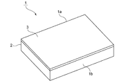
- FIG. 1 is a perspective view showing the appearance of a chip used in the liquid feeding method according to the first embodiment of the present invention.
- FIG. 2 is a schematic plan view for explaining the flow path structure of the chip used in the liquid feeding method according to the first embodiment of the present invention.
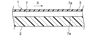
- FIG. 3 is a schematic cross-sectional view showing an enlarged merging flow path in the chip used in the liquid feeding method according to the first embodiment of the present invention.
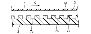
- FIG. 4 is a schematic cross-sectional view showing an enlarged merging flow path of a modified example of the chip used in the liquid feeding method according to the first embodiment of the present invention.
- FIG. 5 is a schematic plan view for explaining the flow path structure of the chip used in the liquid feeding method according to the second embodiment of the present invention.
- FIG. 6 is a schematic plan view showing an enlarged view of the confluence flow path of the chips used in the liquid feeding method according to the second embodiment of the present invention.
- FIG. 7 is an enlarged view showing the merging flow path of the modified example.
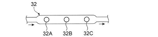
- FIG. 8 is a schematic plan view showing an enlarged view of the mixed liquid sampling section used in Examples 5 and 6 and Comparative Example 2.
- FIG. 9 is a schematic plan view for explaining the flow path structure of the chip used in the comparative example.
- FIG. 1 is a perspective view showing the appearance of a chip used in the liquid feeding method according to the first embodiment of the present invention.
- FIG. 2 is a schematic plan view for explaining the flow path structure of the chip used in the liquid feeding method according to the first embodiment of the present invention.
- the chip 1 used in the liquid feeding method according to the first embodiment of the present invention is an inspection chip.
- the chip 1 can be widely used for inspection, analysis, and the like.
- the chip 1 has a rectangular plate-like shape.
- the shape of the chip 1 is not particularly limited.
- the substrate 2 has a substrate 2 and a cover member 3 provided on the substrate 2.
- the substrate 2 is made of an injection molded product made of synthetic resin.
- the cover member 3 is made of an elastomer or a synthetic resin.
- the substrate 2 and the cover member 3 may be made of other materials.
- the chip 1 may be configured by laminating a plurality of synthetic resin sheets, and is not particularly limited.
- a flow path through which the liquid is sent is provided inside the chip 1.
- the flow path is a micro flow path.
- the flow path may not be a micro flow path but a flow path having a larger cross-sectional area than the micro flow path. However, it is preferably a microchannel. As a result, various tests and analyzes can be performed with a small amount of sample.
- the microchannel means a minute channel that produces a micro effect when the liquid is transported.
- the liquid is strongly affected by surface tension and behaves differently from the liquid flowing through a normal large-sized channel.
- the cross-sectional shape and size of the microchannel are not particularly limited as long as the channel produces the above micro effect.
- the smaller one is when the cross-sectional shape of the microchannel is approximately rectangular (including a square) from the viewpoint of reducing channel resistance.
- the size of the side is preferably 20 ⁇ m or more, more preferably 50 ⁇ m or more, still more preferably 100 ⁇ m or more. From the viewpoint of further miniaturization of the microfluidic device using the chip 1, the size of the smaller side is preferably 5 mm or less, more preferably 1 mm or less, still more preferably 500 ⁇ m or less.
- the diameter (minor diameter in the case of an ellipse) is preferably 20 ⁇ m or more, more preferably 50 ⁇ m or more, still more preferably 100 ⁇ m or more. From the viewpoint of further miniaturization of the microfluidic device, the diameter (minor diameter in the case of an ellipse) is preferably 5 mm or less, more preferably 1 mm or less, and further preferably 500 ⁇ m or less.
- the dimension of the smaller side It is preferably 5 ⁇ m or more, more preferably 10 ⁇ m or more, and further preferably 20 ⁇ m or more. Further, the size of the smaller side is preferably 200 ⁇ m or less, and more preferably 100 ⁇ m or less.
- a flow path structure like the flow path 4 shown in FIG. 2 is configured in the chip 1.
- the flow path 4 has a first flow path 5, a second flow path 6, a confluence flow path 7, and a mixing flow path 8.
- the upstream flow path 4A is formed by the first flow path 5 and the second flow path 6.
- the upstream side flow path 4A is a branch flow path.
- the first flow path 5 and the second flow path 6 are provided to send the first liquid and the second liquid, respectively.
- the first liquid and the second liquid may be microfluidics, respectively.
- the downstream end of the first flow path 5 and the downstream end of the second flow path 6 are connected to the flow path connection portion 9. Further, a merging flow path 7 is connected to the downstream side of the flow path connecting portion 9.
- the merging flow path 7 is a flow path for merging the first liquid and the second liquid.
- the wall surface 7a of the merging flow path 7 shown in FIG. 3 is made of a material having a high affinity with the first liquid.
- a mixing flow path 8 is connected to the downstream end of the merging flow path 7.
- the mixing flow path 8 is a flow path for mixing the first liquid and the second liquid.
- the mixing flow path 8 has a first flow path portion 8a and a second flow path portion 8b.
- the first flow path portion 8a is a recess in which the flow path is expanded toward the first side surface 1a side of the chip 1.
- the second flow path portion 8b is a recess in which the flow path is expanded toward the second side surface 1b side of the chip 1.
- the first flow path portion 8a and the second flow path portion 8b are provided alternately in order from the first flow path portion 8a. By alternately providing the first flow path portion 8a and the second flow path portion 8b in this way, a plurality of liquids can be mixed more accurately.
- the mixing flow path 8 is not particularly limited as long as it is a flow path capable of mixing the first liquid and the second liquid merged in the merging flow path 7.
- the first liquid is sent from the first flow path 5 toward the merging flow path 7.
- This liquid feeding is preferably performed by applying gas from the rear of the first liquid.
- a pump (micropump) that generates such a gas is connected to the first flow path 5.
- the micropump may be provided inside the chip 1 or outside the chip 1 as in the present embodiment.
- a gas generating member arranged in a space connected to the upstream side of the first flow path 5 can be mentioned.
- the gas generating member is a member that generates gas by an external force such as light or heat. By applying an external force to the gas generating member at a predetermined timing, gas can be generated and the gas can be sent to the first flow path 5. Thereby, the first liquid can be sent from the first flow path 5 toward the merging flow path 7.
- the gas generating member include a gas generating tape.
- the liquid feeding means other appropriate means may be used as long as the liquid can be fed from the first flow path 5 toward the merging flow path 7.
- the first liquid is sent to the merging flow path 7 by being pushed by the gas.
- the first liquid is wetted and spread on the wall surface 7a of the merging flow path 7 shown in FIG.
- the wall surface 7a of the merging flow path 7 is made of a material having a high affinity with the first liquid, so that the first liquid is wetted and spread on the wall surface 7a of the merging flow path 7.
- a space through which gas can pass is formed in the merging flow path 7.
- the X direction is the liquid feeding direction, and the merging flow path 7 extends.
- the second liquid is sent from the second flow path 6 to the merging flow path 7.
- the method of feeding the second liquid is also not particularly limited.
- gas is used as in the first liquid feeding method.
- the cost can be further reduced by using the same liquid feeding means for the first liquid and the second liquid.
- the first liquid and the second liquid are merged.
- the first liquid since the first liquid is stopped in the merging flow path 7 in advance, by sending the second liquid to the merging flow path 7, the first liquid can be sent without timing the liquid feeding. The liquid and the second liquid can be surely merged.
- the merged first liquid and second liquid are sent to the mixing flow path 8 by further supplying gas from at least one of the first flow path 5 and the second flow path 6. Thereby, the first liquid and the second liquid are mixed.
- the mixed liquid mixed in the mixing flow path 8 can be discharged from the flow path on the downstream side and recovered.
- the first liquid is previously wetted and spread on the wall surface 7a of the merging flow path 7 to stop the liquid, and a space through which the gas can pass through the merging flow path 7. Is formed. Then, since the second liquid is sent to the merging flow path 7 in this state, the first liquid and the second liquid can be reliably merged without timing the feeding. Thereby, the merged first liquid and the second liquid can be surely mixed in the mixing flow path 8 on the downstream side.
- the liquid feeding method of the present embodiment it is only necessary to wet and spread the first liquid on the wall surface 7a of the merging flow path 7 and to form a space in the merging flow path 7 through which the gas can pass. , The first liquid and the second liquid can be mixed accurately, so that a complicated liquid feed control mechanism is not required. Therefore, it is possible to reduce the size of a device such as a microfluidic device including the chip 1. In addition, the manufacturing cost can be reduced.
- the wall surface 7a has a high affinity with the first liquid.
- the first liquid can be sufficiently wetted and spread on the surface of the wall surface 7a, and a space through which the gas can pass can be formed in the merging flow path 7. .. That is, by increasing the affinity between the wall surface 7a and the first liquid, the required length of the merging flow path 7 can be further shortened, and the chip 1 can be miniaturized and reduced in cost.
- a material having a high affinity with the first liquid may be selected.
- a surface treatment such as hydrophilic treatment or hydrophobic treatment to the wall surface 7a, the affinity between the wall surface 7a and the first liquid is enhanced, whereby the first liquid is wetted with the wall surface 7a of the merging flow path 7.
- a space through which the gas can pass may be formed in the merging flow path 7.
- a surface treatment include a surfactant coating treatment and a plasma surface treatment.
- the wall surface 7a may be roughened, whereby the first liquid may be wetted and spread on the wall surface 7a of the merging flow path 7, and a space through which the gas can pass may be formed in the merging flow path 7.
- the arithmetic mean height Sa of the wall surface 7a is preferably 100 nm or more, more preferably 500 nm or more.
- the upper limit of the arithmetic mean height Sa is not particularly limited, but may be, for example, 1000 nm.
- the arithmetic mean height Sa can be measured in accordance with ISO25178.
- a recess 7c may be repeatedly provided on the bottom surface 7b of the merging flow path 7 toward the liquid feeding direction of the merging flow path 7 to provide a height difference.
- the first liquid may be wetted and spread on the wall surface 7a of the merging flow path 7, and a space through which the gas can pass may be formed in the merging flow path 7.
- the length of the merging flow path 7 can be set shorter.
- the recesses 7c repeatedly provided on the bottom surface 7b of the merging flow path 7 are periodically provided at regular intervals.
- the X direction is the liquid feeding direction, and the merging flow path 7 extends.
- the depth (height difference) of the recess 7c forming the merging flow path 7 is not particularly limited, and is preferably 0.2 mm or more, preferably 1 mm or less.
- the first liquid can be more easily retained by the recess 7c.
- the depth of the recess 7c forming the merging flow path 7 is equal to or less than the above upper limit value, the second liquid is more difficult to stay in the recess 7c, and the mixing flow path 8 on the downstream side makes it easier to supply the liquid. be able to.
- the cross-sectional area of the confluent channel 7 is preferably 0.0004 mm 2 or more, preferably 25 mm 2 or less.
- the cross-sectional area of the merging flow path 7 is equal to or greater than the above lower limit value, it is easier to form a space through which the gas can pass in the merging flow path 7. Further, when the cross-sectional area of the merging flow path 7 is not more than the above upper limit value, it is possible to make it easier to merge the first liquid and the second liquid.
- the length of the merging flow path 7 is appropriately selected depending on the amount of the first liquid sent, the cross-sectional area of the merging flow path 7, the presence or absence of surface treatment, etc., but is preferably 300 mm or less. , More preferably 200 mm or less.
- the lower limit of the length of the merging flow path 7 is not particularly limited, but is, for example, 1 mm or more.
- FIG. 5 is a schematic plan view for explaining the flow path structure of the chip used in the liquid feeding method according to the second embodiment of the present invention.
- the upstream side flow path 24A is not branched and is linear.
- the upstream side flow path 24A is provided with a second liquid holding portion 26 and a first liquid holding portion 25 in this order from the upstream side.
- the upstream side flow path 24A may be a linear flow path, or may be a branched flow path as in the first embodiment.
- the first flow path 5 may be provided with the second liquid holding portion
- the second flow path 6 may be provided with the first liquid holding portion. You may.
- a sample holding portion 22 is provided between the second liquid holding portion 26 and the first liquid holding portion 25.
- the sample held in the sample holding unit 22 can be recovered by the second liquid sent from the second liquid holding unit 26.
- sample held in the sample holding unit 22 examples include body fluids, viruses, bacteria, cells, and extracts thereof.
- the sample holding unit 22 can be used in the form of, for example, a membrane, a filter, a plate, a fibrous material, a tube, particles, a porous material, or the like.
- the sample holding unit 22 can be composed of, for example, silicon compounds, phosphate minerals, silicate minerals, aluminosilicate minerals and the like.
- the sample holding portion 22 is preferably made of silica fiber or glass fiber.
- a merging flow path 27 is provided on the downstream side of the upstream side flow path 24A. Further, a mixing flow path 28 is provided on the downstream side of the merging flow path 27. In FIG. 5, the merging flow path 27 and the mixing flow path 28 are shown in a simplified manner.
- FIG. 6 is an enlarged view showing the confluence flow path of the chips used in the liquid feeding method according to the second embodiment of the present invention.
- the merging flow path 27 of the chip 21 has a zigzag structure in a plan view. Further, in the merging flow path 27, the depth of the flow path is deepened in the shaded portion.
- the first flow path portion 27a having a relatively deep flow path and the second flow path portion 27b having a relatively shallow flow path repeat each other. It is provided alternately.
- the first flow path portion 27a extends in the first direction X1, is refracted by the first bent portion 27c, and is connected to the second flow path portion 27b.
- the second flow path portion 27b extends in the second direction X2, is refracted by the second bent portion 27d, and is connected to the first flow path portion 27a.
- the first bent portion 27c and the second bent portion 27d are bent portions that bend the flow path and also change the depth of the flow path.
- the merging flow path 27 is provided with repeated height differences and has a flat zigzag structure.
- the first liquid can be wetted and spread on the wall surface of the merging flow path 27, and a space through which the gas can pass can be formed in the merging flow path 27.
- the lengths of the first flow path portions 27a are substantially the same.
- the first flow path portions 27a are provided so as to be substantially parallel to each other.
- the lengths of the first flow path portions 27a do not have to be substantially the same, and may not be substantially parallel.
- the lengths of the second flow path portions 27b are provided so as to be substantially the same.
- the second flow path portions 27b are provided so as to be substantially parallel to each other.
- the lengths of the second flow path portions 27b do not have to be substantially the same, and may not be substantially parallel.
- the angle formed by X and X1 can be, for example, 0 ° or more and 90 ° or less. Further, the angle formed by X and X2 can be, for example, 0 ° or more and 90 ° or less.
- the ratio of the depths of the first flow path portion 27a and the second flow path portion 27b is preferably 1 or more, more preferably 1.5. As mentioned above, it is preferably 3 or less, and more preferably 2.5 or less. When the depth ratio (first flow path portion 27a / second flow path portion 27b) is within the above range, it is easier to wet and spread the first liquid more reliably on the wall surface of the merging flow path 27 to stop the liquid. it can.
- the number of Y is preferably 5 or more, more preferably 10 or more. It is preferably 30 or less, more preferably 25 or less.
- the first liquid can be more reliably wetted and spread by the wall surface of the merging flow path 27 to facilitate stopping.
- the height difference may not be repeatedly provided, and only a flat zigzag structure may be provided.
- the first liquid can be wetted and spread on the wall surface of the merging flow path 27, and a space through which the gas can pass can be formed in the merging flow path 27.
- the same configuration as that of the merging flow path 27 of FIG. 6 can be adopted except that the height difference is not repeatedly provided. Further, from the viewpoint of mixing the first liquid and the second liquid more uniformly, it is preferable that the height difference is repeatedly provided as in the merging flow path 27.
- the merging flow path described in the first embodiment may be used. Further, the mixing flow path 28 may also use the mixing flow path described in the first embodiment, and is not particularly limited.
- the chip 21 can also adopt the same configuration as that of the first embodiment having the substrate 2 and the cover member 3 provided on the substrate 2, and the dimensions of the flow path 24 and the like are also the first.
- the configuration described in the embodiment can be adopted.
- the extraction solution containing the sample is injected into the extraction solution holding unit 23A from an injection port (not shown).
- the micropump 30A is driven to send the extraction solution held in the extraction solution holding unit 23A to the sample holding unit 22.
- the sample holding unit 22 holds the sample.
- the cleaning liquid held in the cleaning liquid holding unit 23B is sent to the sample holding unit 22.
- the sample held in the sample holding unit 22 is washed.
- the extract solution and the cleaning solution are sent to the sample holding section 22 and then collected by the sample holding section 22 at the waste liquid section (not shown) on the downstream side. Further, these operations shall be performed in a state where the valve portions 31A and 31B are open and the valve portions 31C and 31D are closed.
- the valve portions 31A and 31B are closed, and the valve portions 31C and 31D are opened.
- the micropump 30B is driven to send the first liquid held in the first liquid holding portion 25 to the merging flow path 27.
- the micropump 30A and the micropump 30B are preferably gas generating members such as a gas generating tape. Specifically, it is preferable to supply the liquid by the pressure of the gas generated by applying light or heat to the gas generating member. In this case, contamination can be made even less likely to occur.
- the first liquid is wetted and spread on the wall surface of the merging flow path 27.
- the first liquid is stopped in the merging flow path 27, and a space through which the gas can pass is formed in the merging flow path 27.
- the second liquid held in the second liquid holding unit 26 is sent to the sample holding unit 22, and the sample held in the sample holding unit 22 is collected.
- the second liquid from which the sample is collected is sent to the merging flow path 27.
- the first liquid and the second liquid are merged. Also in this embodiment, since the first liquid is stopped in the merging flow path 27 in advance, by sending the second liquid to the merging flow path 27, the liquid feeding timing is not required. The liquid 1 and the liquid 2 can be surely merged.
- the merged first liquid and second liquid are sent to the mixing flow path 28. Thereby, the first liquid and the second liquid are mixed.
- the mixed liquid mixed in the mixing flow path 28 can be discharged from the flow path on the downstream side and recovered.
- the first liquid preferably contains a reagent for reacting with the sample.
- the sample and the reaction reagent are uniformly mixed, so that the chemical reaction between the sample and the reaction reagent is uniformly performed in a later step.
- the first liquid preferably contains a polymerase as a reaction reagent with the sample.
- the second liquid preferably contains water.
- the reaction reagent can be appropriately selected according to the sample.
- the first liquid has a higher wettability than the second liquid.
- the first liquid can be more reliably wetted and spread by the wall surface of the merging flow path to facilitate stopping.
- the volume of the first liquid held in the first liquid holding portion is smaller than the volume of the second liquid held in the second liquid holding portion.
- the first liquid can be more reliably wetted and spread on the wall surface of the merging flow path to facilitate stopping, and the second liquid can be more reliably merged with the first liquid.
- the volume of the first liquid held in the first liquid holding portion corresponds to the amount of liquid sent from the first liquid.
- the volume of the second liquid held in the second liquid holding portion corresponds to the amount of liquid sent by the second liquid.
- the ratio (V1 / V2) is preferably 0.5 or less. , More preferably 0.35 or less.
- the first liquid can be more reliably wetted and spread by the wall surface 7a of the merging flow path 7 to facilitate stopping, and the second liquid can be more reliably merged with the first liquid.
- the lower limit of the ratio (V1 / V2) is not particularly limited, but can be, for example, 0.05.
- the amount of the first liquid to be fed is preferably 20 ⁇ L or less, more preferably 10 ⁇ L or less. In this case, the first liquid can be more reliably wetted and spread by the wall surface 7a of the merging flow path 7 to facilitate stopping.
- the lower limit of the amount of the first liquid to be fed is not particularly limited, but may be, for example, 1 ⁇ L.
- the amount of the second liquid to be sent is preferably 20 ⁇ L or more, more preferably 30 ⁇ L or more. In this case, the second liquid can be more reliably merged with the first liquid.
- the upper limit of the amount of the second liquid to be fed is not particularly limited, but can be, for example, 200 ⁇ L.
- the liquid feeding method of the present invention is used for merging and mixing three or more liquids. You may. In that case, three or more flow paths may be connected to the flow path connection portion. Further, in that case, one kind of liquid may be stopped at the merging flow path, or two or more kinds of liquids may be stopped at the merging flow path. The remaining liquids may be merged in that state. Even in that case, a plurality of liquids can be accurately mixed without a complicated liquid feed control mechanism.
- Example 1 a chip 1 having the flow path structure shown in FIG. 2 was produced.
- the chip 1 was produced by attaching a cover member 3 to a substrate 2 which is an injection molded product made of a cycloolefin polymer.
- the merging flow path has a width of 1 mm, a depth of 1 mm, and a length of 60 mm.
- the merging flow path was the merging flow path 27A having a flat zigzag structure shown in FIG. Further, in the extending direction X2 of the second flow path portion 27b, the distance between the flow path centers of the adjacent first flow path portions 27a is set to 1.5 mm. Further, in the extending direction X1 of the first flow path portion 27a, the distance between the flow path centers of the adjacent second flow path portions 27b is set to 1.5 mm.
- the mixed state of the first liquid and the second liquid was measured by the following method.
- the mixing uniformity was evaluated according to the following evaluation criteria.
- the mixed solution after merging and mixing is sent to the measurement flow path (flow path width 1 mm, flow path depth 1 mm, flow path length 100 mm) on the downstream side of the merging flow path 7, and is upstream of the fed mixed solution.
- the vicinity, the vicinity of the middle stream, and the vicinity of the downstream were observed with a fluorescence microscope, and the number of fluorescent particles per unit area was measured.
- Example 2 In Example 2, the merging flow path 27 of FIG. 6 was formed, which was provided with a repeating height difference and had a flat zigzag structure. Further, the chip is the same as in the first embodiment except that the flow path depth of the first flow path portion 27a is 1.3 mm and the flow path depth of the second flow path portion 27b is 0.7 mm. 1 was prepared, and the mixed state and mixing uniformity were evaluated. The position where the first liquid stopped was 20 mm from the upstream end of the merging flow path 7.
- Example 3 In Example 3, a surfactant (sodium dodecyl sulfate (SDS), manufactured by Fuji Film Wako Pure Chemical Industries, Ltd.) was dissolved in water at a ratio of 2.0 wt% on the inner wall surface (wall surface 7a) of the merging flow path 7 shown in FIG. Chip 1 was produced in the same manner as in Example 1 except that the sample was applied to a 5 ⁇ L flow path, and the mixed state and mixing uniformity were evaluated. The position where the first liquid stopped was 50 mm from the upstream end of the merging flow path 7.
- SDS sodium dodecyl sulfate
- the chip 1 is produced in the same manner as in the first embodiment except that the inner wall surface (wall surface 7a) of the merging flow path 7 shown in FIG. 2 is roughened by sandblasting the injection molding die. Then, the mixed state and mixing uniformity were evaluated. The position where the first liquid stopped was 30 mm from the upstream end of the merging flow path 7.
- Comparative Example 1 a chip 101 having the flow path structure shown in FIG. 9 was produced.
- the chip 101 was produced by attaching the cover member 3 to the substrate 2 which is an injection molded product made of a cycloolefin polymer.
- the chip 101 of Comparative Example 1 is directly connected to the mixing flow path from the flow path connection portion (merging point) and does not have a merging flow path.
- the results are shown in Table 1 below.
- the arithmetic mean height (Sa) shown in Table 1 is obtained by observing the inner wall surface of the confocal flow path with a laser microscope (manufactured by Olympus Corporation, model number "LEXT OLS4000") and measuring a range of 2 mm square. It was.
- Example 5 the chip 21 having the flow path structure shown in FIG. 5 was produced.
- the chip 21 was produced by attaching the cover member 3 to the substrate 2 which is an injection molded product made of a cycloolefin polymer.
- As the merging flow path a merging flow path 27 having the structure shown in FIG. 7 was formed.
- the merging flow path 27 has a width of 1 mm and a length of 36 mm. Further, the flow path depth of the first flow path portion 27a was set to 1.3 mm, and the flow path depth of the second flow path portion 27b was set to 0.7 mm.
- the distance between the flow path centers of the adjacent first flow path portions 27a was set to 1.5 mm.
- the distance between the flow path centers of the adjacent second flow path portions 27b was set to 1.5 mm.
- the mixed liquid sampling unit 32 shown in FIG. 8 was provided on the downstream side of the mixing flow path 28.
- the mixed liquid sampling unit 32 was provided with an upstream cell 32A, a middle flow cell 32B, and a downstream cell 32C in order from the upstream side. Evaluation was performed using such a chip 21 as follows.
- DNA purified from Escherichia coli NBRC 12713 strain was prepared as a sample. Purification was performed using the MonoFas Bacterial Genome DNA Extraction Kit (manufactured by GL Sciences).
- the first liquid prepared 1 ⁇ L of “Mighty Amp DNA Polymerase (Takara Bio Inc.)” and 4 ⁇ L of water
- the second liquid 25 ⁇ L of Mighty Amp buffer (manufactured by Takara Bio Inc.) and 20 ⁇ L of water prepared
- the second liquid was sent to the merging flow path 27 using a gas and merged with the first liquid in the merging flow path 27. Then, the merged first liquid and second liquid were sent to the mixing flow path 28 by gas, and the first liquid and the second liquid were mixed.
- the mixed liquid was recovered from the upstream cell 32A, the middle flow cell 32B, and the downstream cell 32C of the mixing and collecting unit 32, respectively.
- the PCR reagents include Primer-F (manufactured by Hokkaido Biosystems) 50 pmol / ⁇ L: 1 ⁇ L, Primer-R (manufactured by Hokkaido Biosystems) 50 pmol / ⁇ L: 1 ⁇ L, and SYBR Green (Lonza): A mixture of 1 ⁇ L was injected into a tube, and the dried product was used.
- the PCR reaction solution prepared from the recovered solution was amplified using a thermal cycler "Light cycler 96 (Roche)". Amplification was performed 40 times in a cycle of 98 ° C.-15 seconds and 67 ° C.-15 seconds after heating at 98 ° C.-120 seconds. From the relationship between the number of PCR cycles and the fluorescence intensity, the Ct value (the point at which the quadratic derivative of the amplification curve is obtained and its maximum) was obtained.
- Example 6 In Example 6, the upstream cell 32A is the same as in Example 5, except that the merging flow path 27 shown in FIG. 6 is changed to the merging flow path 27A shown in FIG. 7 in which the height difference is not provided repeatedly. , The Ct value of the recovered liquid obtained from the middle flow cell 32B and the downstream cell 32C was measured, and the uniformity was evaluated from the variation of the Ct value (standard deviation SD).
- Comparative Example 2 In Comparative Example 2, the Ct values of the recovered liquids obtained from the upstream cell 32A, the middle flow cell 32B, and the downstream cell 32C, respectively, were the same as in the fifth embodiment except that the merging flow path 27 shown in FIG. 6 was not provided. Was measured, and the uniformity was evaluated from the variation in Ct value (standard deviation SD).
Landscapes
- Chemical & Material Sciences (AREA)
- Health & Medical Sciences (AREA)
- Chemical Kinetics & Catalysis (AREA)
- General Health & Medical Sciences (AREA)
- Analytical Chemistry (AREA)
- Dispersion Chemistry (AREA)
- Clinical Laboratory Science (AREA)
- General Physics & Mathematics (AREA)
- Immunology (AREA)
- Pathology (AREA)
- Biochemistry (AREA)
- Physics & Mathematics (AREA)
- Life Sciences & Earth Sciences (AREA)
- Hematology (AREA)
- Automatic Analysis And Handling Materials Therefor (AREA)
- Feeding, Discharge, Calcimining, Fusing, And Gas-Generation Devices (AREA)
- Physical Or Chemical Processes And Apparatus (AREA)
Abstract
複雑な送液制御機構を設けずとも、複数の液体を精度よく混合することができる、送液方法を提供する。 検査チップ1を用いた送液方法であって、第1の液体を上流側流路4Aから合流流路7に送液し、第1の液体を合流流路7の壁面に濡れ広がらせることにより、合流流路7内において第1の液体を停止させる工程と、第2の液体を上流側流路4Aから合流流路7に送液し、第1の液体及び第2の液体を合流させる工程と、合流させた第1の液体及び第2の液体を混合流路8に送液し、第1の液体及び第2の液体を混合させる工程と、を備える、送液方法。
Description
本発明は、液体が送液される流路が設けられているチップを用いた送液方法及び検査チップに関する。
従来、液体が送液される流路が設けられているチップを用いて、各種検体又は試料の送液や反応を制御することにより、血液検査や遺伝子検査などの検査又は生化学分析が試みられている。このような検査用又は分析用のチップにおいては、複数の液体を合流させ、混合することを可能とする流路構造が設けられることがある。
例えば、下記の特許文献1には、液体が流れる3本以上の流路を合流させて液体を混合する混合機構を備えるチップが開示されている。特許文献1のチップでは、液体が流れる3本以上の流路のうちの一部の流路が合流して1本の合流路となり、合流路はその下流側端部において2本以上の分岐路に分岐し、この2本以上の分岐路のうち少なくとも1本に、3本以上の流路のうちの他部の流路が合流されている。
しかしながら、特許文献1のような流路の場合、複数の液体を合流させ均一に混合するには、各液体における送液のタイミングの制御が難しいという問題がある。また、チップ間の寸法バラつき等により、合流タイミングがずれることがあり、この場合、一部の液体が混合されずに通過してしまったり、混合状態が不均一になったりすることがある。そのため、測定結果にもバラつきが生じることがある。
また、各液体における送液のタイミングを精度よく制御するためには、複雑な送液制御機構を有する大掛かりな装置が必要となり、小型化が難しいという問題がある。また、製造コストが高くなるという問題がある。
本発明の目的は、複雑な送液制御機構を設けずとも、複数の液体を精度よく混合することができる、送液方法及び検査チップを提供することにある。
本発明に係る送液方法は、検査チップを用いた送液方法であって、前記検査チップは、第1の液体及び第2の液体を合流させる合流流路と、前記合流流路より下流側において、合流させた前記第1の液体及び前記第2の液体を混合させる混合流路とを備え、前記第1の液体を前記合流流路に送液し、前記第1の液体を前記合流流路の壁面に濡れ広がらせることにより、前記合流流路内において前記第1の液体を停止させる工程と、前記第2の液体を前記合流流路に送液し、前記第1の液体及び前記第2の液体を合流させる工程と、合流させた前記第1の液体及び前記第2の液体を前記混合流路に送液し、第1の液体及び前記第2の液体を混合させる工程と、を備える。
本発明に係る送液方法のある特定の局面では、前記第2の液体を用いて検体を回収した後、前記第1の液体及び前記第2の液体を合流させる。
本発明に係る送液方法の他の特定の局面では、前記検体が、体液、ウイルス、細菌、細胞、又はこれらの抽出物である。
本発明に係る送液方法の他の特定の局面では、前記第1の液体の体積が、前記第2の液体の体積よりも小さい。
本発明に係る送液方法のさらに他の特定の局面では、前記第1の液体は、前記第2の液体よりも濡れ性が高い。
本発明に係る送液方法のさらに他の特定の局面では、前記合流流路の送液方向において、前記合流流路の底部に繰り返し高低差が設けられている。
本発明に係る送液方法のさらに他の特定の局面では、前記合流流路の壁面に表面処理がなされている。
本発明に係る送液方法のさらに他の特定の局面では、前記合流流路の壁面が粗面である。
本発明に係る送液方法のさらに他の特定の局面では、前記第1の液体及び前記第2の液体が、ガス発生部材に光又は熱を加えることにより発生させたガスの圧力によって送液される。
本発明に係る検査チップの広い局面では、第1の液体及び第2の液体が、それぞれ、独立して保持されている、上流側流路と、前記上流側流路よりも下流側において、前記第1の液体及び前記第2の液体を合流させる合流流路と、前記合流流路より下流側において、合流させた前記第1の液体及び前記第2の液体を混合させる混合流路と、を備え、前記合流流路の送液方向において、前記合流流路の底部に繰り返し高低差が設けられている。
本発明に係る検査チップの他の広い局面では、第1の液体及び第2の液体が、それぞれ、独立して保持されている、上流側流路と、前記上流側流路よりも下流側において、前記第1の液体及び前記第2の液体を合流させる合流流路と、前記合流流路より下流側において、合流させた前記第1の液体及び前記第2の液体を混合させる混合流路と、を備え、前記合流流路の壁面に表面処理がなされている。
本発明に係る検査チップの別の広い局面では、第1の液体及び第2の液体が、それぞれ、独立して保持されている、上流側流路と、前記上流側流路よりも下流側において、前記第1の液体及び前記第2の液体を合流させる合流流路と、前記合流流路より下流側において、合流させた前記第1の液体及び前記第2の液体を混合させる混合流路と、を備え、前記合流流路の壁面が粗面である。
本発明に係る検査チップのある特定の局面では、前記上流側流路は、前記第2の液体よりも下流側において、検体を保持するための検体保持部をさらに備える。
本発明によれば、複雑な送液制御機構を設けずとも、複数の液体を精度よく混合することができる、送液方法及び検査チップを提供することができる。
以下、図面を参照しつつ、本発明の具体的な実施形態を説明することにより、本発明を明らかにする。
(第1の実施形態)
図1は、本発明の第1の実施形態に係る送液方法で用いるチップの外観を示す斜視図である。また、図2は、本発明の第1の実施形態に係る送液方法で用いるチップの流路構造を説明するための模式的平面図である。
図1は、本発明の第1の実施形態に係る送液方法で用いるチップの外観を示す斜視図である。また、図2は、本発明の第1の実施形態に係る送液方法で用いるチップの流路構造を説明するための模式的平面図である。
本発明の第1の実施形態に係る送液方法で用いるチップ1は、検査チップである。チップ1は、検査や分析などに幅広く用いることができる。本実施形態において、チップ1は、矩形板状の形状を有する。もっとも、チップ1の形状は、特に限定されない。
本実施形態において、基板2と、基板2上に設けられたカバー部材3とを有する。基板2は、合成樹脂の射出成形体からなる。カバー部材3は、エラストマーや合成樹脂からなる。もっとも、基板2及びカバー部材3は、他の材料により構成されていてもよい。また、チップ1は、複数枚の合成樹脂シートを積層することにより構成されていてもよく、特に限定されない。
チップ1の内部には、液体が送液される流路が設けられている。ここでは、流路がマイクロ流路である。流路は、マイクロ流路ではなく、マイクロ流路よりも断面積の大きな流路であってもよい。もっとも、マイクロ流路であることが好ましい。それによって、微量の試料により、様々な検査や分析を行うことができる。
ところで、マイクロ流路とは、液体の搬送に際し、マイクロ効果が生じるような微細な流路をいう。このようなマイクロ流路では、液体は、表面張力の影響を強く受け、通常の大寸法の流路を流れる液体とは異なる挙動を示す。
マイクロ流路の横断面形状及び大きさは、上記のマイクロ効果が生じる流路であれば特に限定はされない。例えば、マイクロ流路に液体を流す際、ポンプや重力を用いるときに、流路抵抗を低下させる観点から、マイクロ流路の横断面形状がおおむね長方形(正方形を含む)の場合には、小さい方の辺の寸法で、20μm以上が好ましく、50μm以上がより好ましく、100μm以上がさらに好ましい。チップ1を用いたマイクロ流体デバイスのより一層の小型化の観点より、小さい方の辺の寸法で、5mm以下が好ましく、1mm以下がより好ましく、500μm以下がさらに好ましい。
また、マイクロ流路の横断面形状がおおむね円形の場合には、直径(楕円の場合には、短径)が、20μm以上が好ましく、50μm以上がより好ましく、100μm以上がさらに好ましい。マイクロ流体デバイスのより一層の小型化の観点より、直径(楕円の場合には、短径)は、5mm以下が好ましく、1mm以下がより好ましく、500μm以下がさらに好ましい。
一方、例えば、マイクロ流路に液体を流す際、毛細管現象を有効に活用する場合には、マイクロ流路の横断面形状がおおむね長方形(正方形を含む)の場合には、小さい方の辺の寸法で、5μm以上であることが好ましく、10μm以上であることがより好ましく、20μm以上であることがさらに好ましい。また、小さい方の辺の寸法で、200μm以下であることが好ましく、100μm以下であることがさらに好ましい。
本実施形態において、チップ1内には、図2に示す流路4のような流路構造が構成されている。
図2に示すように、流路4は、第1の流路5と、第2の流路6と、合流流路7と、混合流路8とを有する。第1の流路5及び第2の流路6により、上流側流路4Aが構成されている。本実施形態では、上流側流路4Aが分岐流路である。
第1の流路5及び第2の流路6は、それぞれ、第1の液体及び第2の液体を送液するために設けられている。第1の液体及び第2の液体は、それぞれ、マイクロ流体であってもよい。
第1の流路5の下流側端部及び第2の流路6の下流側端部は、流路接続部9に接続されている。また、流路接続部9の下流側には、合流流路7が接続されている。
合流流路7は、第1の液体及び第2の液体を合流させるための流路である。本実施形態では、図3に示す合流流路7の壁面7aが第1の液体との親和性の高い材料により構成されている。また、合流流路7の下流側端部には、混合流路8が連ねられている。
混合流路8は、第1の液体及び第2の液体を混合させるための流路である。本実施形態では、混合流路8は、第1の流路部8aと第2の流路部8bとを有する。第1の流路部8aは、チップ1の第1の側面1a側に流路が拡大されている凹部である。第2の流路部8bは、チップ1の第2の側面1b側に流路が拡大されている凹部である。また、第1の流路部8a及び第2の流路部8bは、第1の流路部8aから順に交互に設けられている。このように、第1の流路部8a及び第2の流路部8bを交互に設けることにより、複数の液体をより一層精度よく混合することができる。もっとも、混合流路8は、合流流路7で合流された第1の液体及び第2の液体を混合できる流路であればよく、特に限定されない。
以下、チップ1を用いた送液方法の一例について説明する。
まず、第1の液体を、第1の流路5から合流流路7に向かって送液する。この送液は、好ましくは、第1の液体の後方から、ガスを付与することにより行なわれる。このようなガスを発生するポンプ(マイクロポンプ)が、第1の流路5に連結されている。マイクロポンプは、本実施形態のように、チップ1の内部に設けられていてもよいし、チップ1の外部に設けられていてもよい。
また、他の送液手段としては、第1の流路5より上流側に連結された空間に配置されたガス発生部材が挙げられる。ガス発生部材とは、光や熱等の外力によりガスを発生する部材である。ガス発生部材に所定のタイミングで外力を加えることによりガスを発生させ、第1の流路5にガスを送り込むことができる。それによって、第1の液体を、第1の流路5から合流流路7に向かって送液することができる。ガス発生部材としては、例えば、ガス発生テープが挙げられる。なお、送液手段は、第1の流路5から合流流路7に向かって送液することができることができる限りにおいて、他の適宜の手段を用いてもよい。
本実施形態では、上記ガスに押されることにより、第1の液体が、合流流路7に送液される。本実施形態の送液方法では、図3に示す合流流路7の壁面7aに第1の液体を濡れ広がらせる。それによって、第1の液体を合流流路7内で停止させるとともに、合流流路7内に気体が通過することのできる空間を形成する。なお、本実施形態では、合流流路7の壁面7aを第1の液体との親和性の高い材料により構成することにより、第1の液体を合流流路7の壁面7aに濡れ広がらせるとともに、合流流路7内に気体が通過することのできる空間を形成している。なお、図3においては、X方向が送液方向であり、合流流路7が延びる方向である。
次に、第2の流路6から、第2の液体を合流流路7に送液する。第2の液体の送液方法についても、特に限定されない。好ましくは、第1の液体の送液方法と同様に、ガスが用いられる。その場合には、第1の液体及び第2の液体の送液手段を同じとすることにより、コストのより一層の低減を果たすことができる。
第2の液体を合流流路7に送液することにより、第1の液体及び第2の液体を合流させる。本実施形態では、予め第1の液体が合流流路7内において停止しているため、第2の液体を合流流路7に送液することにより、送液のタイミングを図らずとも、第1の液体及び第2の液体を確実に合流させることができる。
次に、第1の流路5及び第2の流路6の少なくとも一方から、さらにガスを供給することにより、合流した第1の液体及び第2の液体を混合流路8に送液する。それによって、第1の液体及び第2の液体を混合させる。混合流路8で混合された混合液は、さらに下流側の流路から排出し、回収することができる。
従来、複数の液体を合流させ均一に混合するには、各液体における送液のタイミングの制御が難しいという問題がある。また、チップ間の寸法バラつき等により、合流タイミングがずれることがあり、複数の液体が合流できずに分離した状態で通過してしまうことがある。そのため、混合状態が不均一になり、精度よく混合できないという問題がある。この場合、測定結果にもバラつきが生じることがある。
これに対して、本実施形態の送液方法では、予め第1の液体を合流流路7の壁面7aに濡れ広がらせて停止させるとともに、合流流路7内に気体が通過することのできる空間を形成しておく。そして、この状態で、第2の液体を合流流路7に送液するため、送液のタイミングを図らずとも、第1の液体及び第2の液体を確実に合流させることができる。それによって、下流側の混合流路8において、合流した第1の液体及び第2の液体を確実に混合することができる。
また、本実施形態の送液方法では、第1の液体を合流流路7の壁面7aに濡れ広がらせるとともに、合流流路7内に気体が通過することのできる空間を形成しておくだけで、第1の液体及び第2の液体を精度よく混合することができるため、複雑な送液制御機構を必要としない。そのため、チップ1を含むマイクロ流体デバイスなどのデバイスの小型化を図ることができる。また、製造コストを低減することもできる。
合流流路7では、壁面7aと第1の液体との親和性が高いことが好ましい。この場合、合流流路7の長さを短くしたとしても、第1の液体を壁面7aの表面上に十分濡れ広がらせるとともに、合流流路7内に気体が通過することのできる空間を形成できる。すなわち、壁面7aと第1の液体との親和性を高めることによって、必要な合流流路7の長さをより短くすることができ、チップ1の小型化や低コスト化を達成できる。
例えば、合流流路7の壁面7aを構成する材料として、第1の液体との親和性の高い材料を選択してもよい。また、壁面7aに親水処理や疎水処理のような表面処理を施すことにより、壁面7aと第1の液体との親和性を高め、それによって第1の液体を合流流路7の壁面7aに濡れ広がらせるとともに、合流流路7内に気体が通過することのできる空間を形成してもよい。このような表面処理としては、例えば、界面活性剤の塗布処理、プラズマによる表面処理などが挙げられる。
あるいは、壁面7aを粗面化し、それによって第1の液体を合流流路7の壁面7aに濡れ広がらせるとともに、合流流路7内に気体が通過することのできる空間を形成してもよい。この場合、壁面7aの算術平均高さSaは、好ましくは100nm以上、より好ましくは500nm以上である。算術平均高さSaの上限値は特に限定されないが、例えば、1000nmとすることができる。なお、算術平均高さSaは、ISO25178に準拠して測定することができる。
あるいは、図4に示すように、合流流路7の送液方向に向かって、合流流路7の底面7bに繰り返し凹部7cを設け、高低差を設けてもよい。それによって、第1の液体を合流流路7の壁面7aに濡れ広がらせるとともに、合流流路7内に気体が通過することのできる空間を形成してもよい。また、この場合、第1の液体を凹部7cに滞留し易くすることができるため、合流流路7の長さをより短く設定することもできる。また、図4に示すように、合流流路7の底面7bに繰り返し設けられる凹部7cは、一定の間隔で周期的に設けられていることが好ましい。なお、図4においても、X方向が送液方向であり、合流流路7が延びる方向である。
また、この場合、合流流路7を形成する凹部7cの深さ(高低差)は、特に限定されず、好ましくは0.2mm以上、好ましくは1mm以下である。合流流路7を形成する凹部7cの深さが上記下限値以上である場合、第1の液体を凹部7cにより一層滞留し易くすることができる。また、合流流路7を形成する凹部7cの深さが上記上限値以下である場合、第2の液体が凹部7cにより一層滞留し難く、下流側の混合流路8により一層送液し易くすることができる。
本発明においては、合流流路7の断面積が、好ましくは0.0004mm2以上、好ましくは25mm2以下である。合流流路7の断面積が上記下限値以上である場合、合流流路7内に気体が通過することのできる空間をより一層形成し易い。また、合流流路7の断面積が上記上限値以下である場合、第1の液体と第2の液体をより一層合流し易くすることができる。
本発明において、合流流路7の長さは、第1の液体の送液量や合流流路7の断面積、表面処理の有無等に応じて適宜選択されるが、好ましくは300mm以下であり、より好ましくは200mm以下である。合流流路7の長さが上記上限値以下である場合、チップ1の小型化や低コスト化を達成しやすい。なお、合流流路7の長さの下限値は、特に限定されないが、例えば1mm以上である。
(第2の実施形態)
図5は、本発明の第2の実施形態に係る送液方法で用いるチップの流路構造を説明するための模式的平面図である。図5に示すように、チップ21では、上流側流路24Aが分岐しておらず、直線状である。上流側流路24Aには、上流側から順に第2の液体保持部26及び第1の液体保持部25が設けられている。このように、上流側流路24Aは、直線状流路であってもよく、第1の実施形態のように、分岐状流路であってもよい。なお、第1の実施形態においても、例えば、第1の流路5に第2の液体保持部が設けられていてもよく、第2の流路6に第1の液体保持部が設けられていてもよい。
図5は、本発明の第2の実施形態に係る送液方法で用いるチップの流路構造を説明するための模式的平面図である。図5に示すように、チップ21では、上流側流路24Aが分岐しておらず、直線状である。上流側流路24Aには、上流側から順に第2の液体保持部26及び第1の液体保持部25が設けられている。このように、上流側流路24Aは、直線状流路であってもよく、第1の実施形態のように、分岐状流路であってもよい。なお、第1の実施形態においても、例えば、第1の流路5に第2の液体保持部が設けられていてもよく、第2の流路6に第1の液体保持部が設けられていてもよい。
また、チップ21では、第2の液体保持部26及び第1の液体保持部25の間に検体保持部22が設けられている。検体保持部22に保持されている検体は、第2の液体保持部26から送液される第2の液体により回収することができる。
検体保持部22に保持される検体としては、例えば、体液、ウイルス、細菌、細胞、又はこれらの抽出物が挙げられる。なお、検体保持部22は、例えば、膜、フィルター、プレート、繊維状、チューブ、粒子、多孔質等の形態で用いることができる。また、検体保持部22は、例えば、ケイ素化合物類、リン酸塩鉱物類、ケイ酸塩鉱物類、又はアルミノケイ酸塩鉱物類等により構成することができる。なかでも、検体保持部22は、シリカ繊維やガラス繊維であることが好ましい。
また、チップ21においても、上流側流路24Aより下流側に、合流流路27が設けられている。また、合流流路27より下流側に混合流路28が設けられている。なお、図5では、合流流路27及び混合流路28を簡略化して示している。
図6は、本発明の第2の実施形態に係る送液方法で用いるチップの合流流路を拡大して示す図である。
図6に示すように、チップ21の合流流路27は、平面視において、ジグザグ構造を有している。また、合流流路27では、斜線部において、流路の深さが深くされている。
具体的には、合流流路27では、流路の深さが相対的に深い第1の流路部27aと、流路の深さが相対的に浅い第2の流路部27bとが繰り返し交互に設けられている。第1の流路部27aは、第1の方向X1に延びており、第1の屈曲部27cで屈折して第2の流路部27bに連なっている。第2の流路部27bは、第2の方向X2に延びており、第2の屈曲部27dで屈折して第1の流路部27aに連なっている。なお、第1の屈曲部27c及び第2の屈曲部27dは、流路を屈曲させるとともに、流路の深さも変化させる屈曲部である。このようにして、繰り返し高低差が設けられており、平面ジグザグ構造を有する、合流流路27が構成されている。これにより、チップ21では、第1の液体を合流流路27の壁面に濡れ広がらせるとともに、合流流路27内に気体が通過することのできる空間を形成することができる。
本実施形態においては、各第1の流路部27aの長さが略同一となるように設けられている。各第1の流路部27aが略平行となるように設けられている。もっとも、各第1の流路部27aの長さは略同一でなくてもよく、略平行でなくともよい。
また、各第2の流路部27bの長さが略同一となるように設けられている。各第2の流路部27bが略平行となるように設けられている。もっとも、各第2の流路部27bの長さは略同一でなくてもよく、略平行でなくともよい。
本実施形態において、流路の進行方向をXとしたときに、XとX1のなす角度は、例えば、0°以上、90°以下とすることができる。また、XとX2のなす角度は、例えば、0°以上、90°以下とすることができる。
第1の流路部27a及び第2の流路部27bの深さの比(第1の流路部27a/第2の流路部27b)は、好ましくは1以上、より好ましくは1.5以上、好ましくは3以下、より好ましくは2.5以下である。深さの比(第1の流路部27a/第2の流路部27b)が上記範囲内にある場合、第1の液体を合流流路27の壁面により一層確実に濡れ広げて停止させ易くできる。
本実施形態においては、一組の第1の流路部27a及び第2の流路部27bを繰り返しの単位Yとしたときに、Yの数が、好ましくは5以上、より好ましくは10以上、好ましくは30以下、より好ましくは25以下である。Yの数が上記範囲内にある場合、第1の液体を合流流路27の壁面により一層確実に濡れ広げて停止させ易くできる。
なお、本発明においては、図7に示す変形例の合流流路27Aのように、繰り返し高低差が設けられておらず、平面ジグザグ構造のみが設けられていてもよい。この場合においても、第1の液体を合流流路27の壁面に濡れ広がらせるとともに、合流流路27内に気体が通過することのできる空間を形成することができる。なお、この場合、繰り返し高低差が設けられていないこと以外は、図6の合流流路27と同様の構成を採用することができる。また、第1の液体及び第2の液体をより一層均一に混合する観点からは、合流流路27のように繰り返し高低差が設けられていることが好ましい。
なお、合流流路27は、第1の実施形態で説明した合流流路を用いてもよい。また、混合流路28についても、第1の実施形態で説明した混合流路を用いてもよく、特に限定されない。
チップ21においても、基板2と、基板2上に設けられたカバー部材3とを有する第1の実施形態と同様の構成を採用することができ、また流路24の寸法等についても第1の実施形態で説明した構成を採用することができる。
以下、チップ21を用いた送液方法の一例について説明する。
まず、検体を含む抽出溶液を、抽出溶液保持部23Aに注入口(図示せず)から注入する。次に、マイクロポンプ30Aを駆動し、抽出溶液保持部23Aに保持された抽出溶液を検体保持部22に送液する。これにより、検体保持部22において検体を保持させる。次に、洗浄液保持部23Bに保持された洗浄液を検体保持部22に送液する。これにより、検体保持部22に保持された検体を洗浄する。なお、抽出溶液及び洗浄液は、検体保持部22に送液した後、検体保持部22により下流側の廃液部(図示せず)で回収する。また、これらの操作は、弁部31A及び31Bが開放されており、弁部31C及び31Dは閉止されている状態で行うものとする。
次に、弁部31A及び31Bを閉止し、弁部31C及び31Dを開放する。次に、マイクロポンプ30Bを駆動し、第1の液体保持部25に保持された第1の液体を合流流路27に送液する。なお、マイクロポンプ30A及びマイクロポンプ30Bは、第1の実施形態で説明したものを用いることができる。なかでも、マイクロポンプ30A及びマイクロポンプ30Bは、ガス発生テープのようなガス発生部材であることが好ましい。具体的には、ガス発生部材に光又は熱を加えることにより発生させたガスの圧力によって送液することが好ましい。この場合、コンタミをより一層生じ難くすることができる。
本実施形態の送液方法では、合流流路27の壁面に第1の液体を濡れ広がらせる。それによって、第1の液体を合流流路27内で停止させるとともに、合流流路27内に気体が通過することのできる空間を形成する。
一方で、第2の液体保持部26に保持された第2の液体を検体保持部22に送液し、検体保持部22に保持された検体を回収する。次に、検体を回収した第2の液体を合流流路27に送液する。
第2の液体を合流流路27に送液することにより、第1の液体及び第2の液体を合流させる。本実施形態においても、予め第1の液体が合流流路27内において停止しているため、第2の液体を合流流路27に送液することにより、送液のタイミングを図らずとも、第1の液体及び第2の液体を確実に合流させることができる。
次に、さらにガスを供給することにより、合流した第1の液体及び第2の液体を混合流路28に送液する。それによって、第1の液体及び第2の液体を混合させる。混合流路28で混合された混合液は、さらに下流側の流路から排出し、回収することができる。
第2の実施形態の送液方法のように、第2の液体により検体を回収した後、第1の液体と合流させ、混合してもよい。この場合、第1の液体は、検体との反応試薬を含むことが好ましい。第1の液体が検体との反応試薬を含む場合、検体と反応試薬とが均一に混合されるため、後の工程において検体と反応試薬との化学反応が均一に行われる。
例えば、検体が核酸である場合、第1の液体は、検体との反応試薬としてポリメラーゼを含むことが好ましい。また、第2の液体は水を含むことが好ましい。なお、反応試薬は検体に合わせて適宜選択することができる。
本発明において、第1の液体は、第2の液体よりも濡れ性が高いことが好ましい。この場合、第1の液体を合流流路の壁面により一層確実に濡れ広げて停止させ易くできる。
また、本発明においては、第1の液体保持部に保持される第1の液体の体積が、第2の液体保持部に保持される第2の液体の体積よりも小さいことが好ましい。この場合、第1の液体を合流流路の壁面により一層確実に濡れ広げて停止させ易くできるとともに、第2の液体を第1の液体とより一層確実に合流させることができる。なお、第1の液体保持部に保持される第1の液体の体積は、第1の液体の送液量に相当する。また、第2の液体保持部に保持される第2の液体の体積は、第2の液体の送液量に相当する。
また、本発明においては、第1の液体の送液量をV1とし、第2の液体の送液量をV2としたときに、比(V1/V2)が、好ましくは0.5以下であり、より好ましくは0.35以下である。この場合、第1の液体を合流流路7の壁面7aにより一層確実に濡れ広げて停止させ易くできるとともに、第2の液体を第1の液体とより一層確実に合流させることができる。上記比(V1/V2)の下限値は、特に限定されないが、例えば、0.05とすることができる。
第1の液体の送液量は、好ましくは20μL以下であり、より好ましくは10μL以下である。この場合、第1の液体を合流流路7の壁面7aにより一層確実に濡れ広げて停止させ易くできる。また、第1の液体の送液量の下限値は、特に限定されないが、例えば、1μLとすることができる。
第2の液体の送液量は、好ましくは20μL以上、より好ましくは30μL以上である。この場合、第2の液体を第1の液体とより一層確実に合流させることができる。また、第2の液体の送液量の上限値は、特に限定されないが、例えば、200μLとすることができる。
なお、各実施形態の送液方法の説明では、第1の液体及び第2の液体の合流及び混合方法について説明したが、本発明の送液方法は、3以上の液体の合流及び混合に用いてもよい。その場合、3つ以上の流路を流路接続部に接続してもよい。また、その場合、1種類の液体を合流流路で停止させておいてもよいし、2種以上の液体を合流流路で停止させておいてもよい。その状態で残りの液体を合流させてもよい。その場合においても、複雑な送液制御機構がなくとも、複数の液体を精度よく混合することができる。
以下、本発明の具体的な実施例及び比較例を挙げることにより、本発明を明らかにする。なお、本発明は以下の実施例に限定されるものではない。
(実施例1)
実施例1では、図2に示す流路構造を有するチップ1を作製した。チップ1は、シクロオレフィンポリマーからなる射出成型体である基板2に、カバー部材3を貼り合わせることにより作製した。合流流路は、幅1mm、深さ1mm、長さ60mmとした。なお、合流流路は、図7に示す平面ジグザグ構造の合流流路27Aとした。また、第2の流路部27bの延びる方向X2において、隣り合う第1の流路部27aにおける流路中心間の距離を1.5mmとした。また、第1の流路部27aの延びる方向X1において、隣り合う第2の流路部27bにおける流路中心間の距離を1.5mmとした。
実施例1では、図2に示す流路構造を有するチップ1を作製した。チップ1は、シクロオレフィンポリマーからなる射出成型体である基板2に、カバー部材3を貼り合わせることにより作製した。合流流路は、幅1mm、深さ1mm、長さ60mmとした。なお、合流流路は、図7に示す平面ジグザグ構造の合流流路27Aとした。また、第2の流路部27bの延びる方向X2において、隣り合う第1の流路部27aにおける流路中心間の距離を1.5mmとした。また、第1の流路部27aの延びる方向X1において、隣り合う第2の流路部27bにおける流路中心間の距離を1.5mmとした。
このようなチップ1を用いて、第1の液体としての蛍光粒子(粒子径1μm、発光波長485.56nm)を分散させた水7μLを合流流路7にガスを用いて送液し、合流流路7で停止させた。第1の液体が停止した位置は、合流流路7の上流端から40mmの位置であった。次に、第2の液体としての水21μLを合流流路7にガスを用いて送液し、合流流路7内において第1の液体に合流させた。そして、合流した第1の液体及び第2の液体をガスにより混合流路8に送液し、第1の液体及び第2の液体を混合した。
次に、第1の液体及び第2の液体の混合状態を以下の方法により測定した。また、以下の評価基準により、混合均一性を評価した。
合流、混合後の混合液を合流流路7の下流側の測定流路(流路幅1mm、流路深さ1mm、流路長さ100mm)に送液し、送液された混合液の上流付近、中流付近、下流付近を蛍光顕微鏡で観察し、単位面積当たりの蛍光粒子数を測定した。
<評価基準>
〇…上流、中流、下流の蛍光粒子数のばらつきが±20%以内
×…上流、中流、下流の蛍光粒子数のばらつきが±50%以上
〇…上流、中流、下流の蛍光粒子数のばらつきが±20%以内
×…上流、中流、下流の蛍光粒子数のばらつきが±50%以上
(実施例2)
実施例2では、繰り返し高低差が設けられており、平面ジグザグ構造を有する、図6の合流流路27を形成した。また、第1の流路部27aの流路深さを1.3mmとし、第2の流路部27bの流路深さを0.7mmとしたこと以外は、実施例1と同様にしてチップ1を作製し、混合状態及び混合均一性を評価した。なお、第1の液体が停止した位置は、合流流路7の上流端から20mmの位置であった。
実施例2では、繰り返し高低差が設けられており、平面ジグザグ構造を有する、図6の合流流路27を形成した。また、第1の流路部27aの流路深さを1.3mmとし、第2の流路部27bの流路深さを0.7mmとしたこと以外は、実施例1と同様にしてチップ1を作製し、混合状態及び混合均一性を評価した。なお、第1の液体が停止した位置は、合流流路7の上流端から20mmの位置であった。
(実施例3)
実施例3では、図2に示す合流流路7の内壁面(壁面7a)に界面活性剤(ドデシル硫酸ナトリウム(SDS)、富士フィルム和光純薬社製)を水に2.0wt%の割合で溶解したものを5μL流路に塗布したこと以外は、実施例1と同様にしてチップ1を作製し、混合状態及び混合均一性を評価した。なお、第1の液体が停止した位置は、合流流路7の上流端から50mmの位置であった。
実施例3では、図2に示す合流流路7の内壁面(壁面7a)に界面活性剤(ドデシル硫酸ナトリウム(SDS)、富士フィルム和光純薬社製)を水に2.0wt%の割合で溶解したものを5μL流路に塗布したこと以外は、実施例1と同様にしてチップ1を作製し、混合状態及び混合均一性を評価した。なお、第1の液体が停止した位置は、合流流路7の上流端から50mmの位置であった。
(実施例4)
実施例4では、射出成型金型をサンドブラストすることにより、図2に示す合流流路7の内壁面(壁面7a)を粗面としたこと以外は、実施例1と同様にしてチップ1を作製し、混合状態及び混合均一性を評価した。なお、第1の液体が停止した位置は、合流流路7の上流端から30mmの位置であった。
実施例4では、射出成型金型をサンドブラストすることにより、図2に示す合流流路7の内壁面(壁面7a)を粗面としたこと以外は、実施例1と同様にしてチップ1を作製し、混合状態及び混合均一性を評価した。なお、第1の液体が停止した位置は、合流流路7の上流端から30mmの位置であった。
(比較例1)
比較例1では、図9に示す流路構造を有するチップ101を作製した。チップ101は、シクロオレフィンポリマーからなる射出成型体である基板2にカバー部材3を貼り合わせることにより作製した。なお、比較例1のチップ101は、流路接続部(合流点)から直接混合流路へとつながっており、合流流路を有していない。
比較例1では、図9に示す流路構造を有するチップ101を作製した。チップ101は、シクロオレフィンポリマーからなる射出成型体である基板2にカバー部材3を貼り合わせることにより作製した。なお、比較例1のチップ101は、流路接続部(合流点)から直接混合流路へとつながっており、合流流路を有していない。
このようなチップ101を用いて、第1の液体としての蛍光粒子(粒子径1μm、発光波長485.56nm)を分散させた水7μLと、第2の液体としての水21μLをそれぞれ第1の流路5、第2の流路6から同じタイミングでガスを用いて送液し、流路接続部を経て混合流路8へと送液し、第1の液体及び第2の液体を混合した。次に、実施例1と同様の方法で混合状態及び混合均一性を評価した。
結果を下記の表1に示す。なお、表1に示す算術平均高さ(Sa)は、合流流路の内壁面をレーザー顕微鏡(オリンパス社製、型番「LEXT OLS4000」)で表面観察し、2mm四方の範囲を計測することにより求めた。

表1より、実施例1~4では、比較例1と比較して、蛍光粒子数のバラつきが少なく、より精度よく混合できていることが確認できた。
(実施例5)
実施例5では、図5に示す流路構造を有するチップ21を作製した。チップ21は、シクロオレフィンポリマーからなる射出成型体である基板2に、カバー部材3を貼り合わせることにより作製した。なお、合流流路としては、図7に示す構造を有する合流流路27を形成した。合流流路27は、幅1mm及び長さ36mmとした。また、第1の流路部27aの流路深さを1.3mmとし、第2の流路部27bの流路深さを0.7mmとした。第2の流路部27bの延びる方向X2において、隣り合う第1の流路部27aにおける流路中心間の距離を1.5mmとした。第1の流路部27aの延びる方向X1において、隣り合う第2の流路部27bにおける流路中心間の距離を1.5mmとした。
実施例5では、図5に示す流路構造を有するチップ21を作製した。チップ21は、シクロオレフィンポリマーからなる射出成型体である基板2に、カバー部材3を貼り合わせることにより作製した。なお、合流流路としては、図7に示す構造を有する合流流路27を形成した。合流流路27は、幅1mm及び長さ36mmとした。また、第1の流路部27aの流路深さを1.3mmとし、第2の流路部27bの流路深さを0.7mmとした。第2の流路部27bの延びる方向X2において、隣り合う第1の流路部27aにおける流路中心間の距離を1.5mmとした。第1の流路部27aの延びる方向X1において、隣り合う第2の流路部27bにおける流路中心間の距離を1.5mmとした。
また、混合流路28より下流側に図8に示す混合液採取部32を設けた。なお、混合液採取部32には、上流側から順に、上流セル32A、中流セル32B、下流セル32Cを設けた。このようなチップ21を用いて以下のようにして評価を行った。
まず、検体として、大腸菌 NBRC 12713株(独立行政法人製品評価技術基盤機構より入手)から精製したDNAを用意した。なお、精製は、MonoFasバクテリアゲノムDNA抽出キット(ジーエル サイエンス社製)により行った。
次に、大腸菌 NBRC 12713株精製DNA(10,000コピー/μL)1μLと、QIAGEN社製、Carrier RNA(polyA、3μg/μL)1μLとを、尿素4M、グアニジン塩酸塩4M、塩化カルシウム2Mを含む水溶液(pH7.0)148μLに添加し、核酸を含む抽出溶液150μLを調整した。
次に、核酸を含む抽出溶液150μLを抽出溶液保持部23Aから検体保持部22へ送液することにより、検体保持部22のシリカ繊維フィルターに核酸を吸着させた。次に、洗浄液(メラミン50mM、pH4.0の水溶液)400μLを検体保持部22に送液し、核酸を洗浄した。
次に、第1の液体保持部25から、第1の液体(「MightyAmp DNA Polymerase(タカラバイオ社)」1μL及び水4μLを調製したもの)5μLを合流流路27にガスを用いて送液し、合流流路27の壁面に濡れ広がらせることにより停止させた。一方、第2の液体保持部26から、第2の液体(MightyAmp buffer(タカラバイオ社製)25μL及び水20μLを調製したもの)45μLを検体保持部22にガスを用いて送液し、核酸を回収した。さらに、第2の液体を合流流路27にガスを用いて送液し、合流流路27内において第1の液体に合流させた。そして、合流した第1の液体及び第2の液体をガスにより混合流路28に送液し、第1の液体及び第2の液体を混合した。なお、混合液は、混合採取部32の上流セル32A、中流セル32B、及び下流セル32Cから、それぞれ、回収した。
次に、各セルにおいてそれぞれ核酸を回収した回収液5μLと、PCR用試薬とを混合して、PCR反応溶液を調整した。なお、PCR用試薬としては、Primer-F(北海道バイオシステム社受託製造)50pmol/μL:1μL、Primer-R(北海道バイオシステム社受託製造)50pmol/μL:1μL、及びSYBR Green(ロンザ社):1μLを混合させたものをチューブに注入し、乾燥させたものを用いた。
次に、回収液から調製したPCR反応溶液をサーマルサイクラー「Light cycler 96(Roche社)」を用いて増幅した。増幅は98℃-120秒にて加熱した後、98℃-15秒、67℃-15秒のサイクルを40回行った。PCRサイクル数及び蛍光強度の関係から、Ct値(増幅曲線の2次導関数を求めてそれが最大となる点)を求めた。
このようにして、上流セル32A、中流セル32B、下流セル32Cからそれぞれ得られた回収液のCt値を測定し、Ct値のばらつき(標準偏差SD)から均一性を評価した。
(実施例6)
実施例6では、図6に示す合流流路27を、繰り返しの高低差が設けられていない図7に示す合流流路27Aに変更したこと以外は、実施例5と同様にして、上流セル32A、中流セル32B、下流セル32Cからそれぞれ得られた回収液のCt値を測定し、Ct値のばらつき(標準偏差SD)から均一性を評価した。
実施例6では、図6に示す合流流路27を、繰り返しの高低差が設けられていない図7に示す合流流路27Aに変更したこと以外は、実施例5と同様にして、上流セル32A、中流セル32B、下流セル32Cからそれぞれ得られた回収液のCt値を測定し、Ct値のばらつき(標準偏差SD)から均一性を評価した。
(比較例2)
比較例2では、図6に示す合流流路27を設けなかったこと以外は、実施例5と同様にして、上流セル32A、中流セル32B、下流セル32Cからそれぞれ得られた回収液のCt値を測定し、Ct値のばらつき(標準偏差SD)から均一性を評価した。
比較例2では、図6に示す合流流路27を設けなかったこと以外は、実施例5と同様にして、上流セル32A、中流セル32B、下流セル32Cからそれぞれ得られた回収液のCt値を測定し、Ct値のばらつき(標準偏差SD)から均一性を評価した。
結果を下記の表2に示す。

表2より、実施例5~6では、比較例2と比較して、Ct値のバラつきが小さく、より精度よく混合できていることが確認できた。
1,21…チップ
1a…第1の側面
1b…第2の側面
2…基板
3…カバー部材
4,24…流路
4A,24A…上流側流路
5…第1の流路
6…第2の流路
7,27,27A…合流流路
7a…壁面
7b…底面
7c…凹部
8,28…混合流路
8a…第1の流路部
8b…第2の流路部
9…流路接続部
22…検体保持部
23A…抽出溶液保持部
23B…洗浄液保持部
25…第1の液体保持部
26…第2の液体保持部
27a…第1の流路部
27b…第2の流路部
27c…第1の屈曲部
27d…第2の屈曲部
30A,30B…マイクロポンプ
31A~31D…弁部
32…混合液採取部
32A…上流セル
32B…中流セル
32C…下流セル
Claims (13)
- 検査チップを用いた送液方法であって、
前記検査チップは、第1の液体及び第2の液体を合流させる合流流路と、前記合流流路より下流側において、合流させた前記第1の液体及び前記第2の液体を混合させる混合流路とを備え、
前記第1の液体を前記合流流路に送液し、前記第1の液体を前記合流流路の壁面に濡れ広がらせることにより、前記合流流路内において前記第1の液体を停止させる工程と、
前記第2の液体を前記合流流路に送液し、前記第1の液体及び前記第2の液体を合流させる工程と、
合流させた前記第1の液体及び前記第2の液体を前記混合流路に送液し、第1の液体及び前記第2の液体を混合させる工程と、
を備える、送液方法。 - 前記第2の液体を用いて検体を回収した後、前記第1の液体及び前記第2の液体を合流させる、請求項1に記載の送液方法。
- 前記検体が、体液、ウイルス、細菌、細胞、又はこれらの抽出物である、請求項1又は2に記載の送液方法。
- 前記第1の液体の体積が、前記第2の液体の体積よりも小さい、請求項1~3のいずれか1項に記載の送液方法。
- 前記第1の液体は、前記第2の液体よりも濡れ性が高い、請求項1~4のいずれか1項に記載の送液方法。
- 前記合流流路の送液方向において、前記合流流路の底部に繰り返し高低差が設けられている、請求項1~5のいずれか1項に記載の送液方法。
- 前記合流流路の壁面に表面処理がなされている、請求項1~6のいずれか1項に記載の送液方法。
- 前記合流流路の壁面が粗面である、請求項1~7のいずれか1項に記載の送液方法。
- 前記第1の液体及び前記第2の液体が、ガス発生部材に光又は熱を加えることにより発生させたガスの圧力によって送液される、請求項1~8のいずれか1項に記載の送液方法。
- 第1の液体及び第2の液体が、それぞれ、独立して保持されている、上流側流路と、
前記上流側流路よりも下流側において、前記第1の液体及び前記第2の液体を合流させる合流流路と、
前記合流流路より下流側において、合流させた前記第1の液体及び前記第2の液体を混合させる混合流路と、
を備え、
前記合流流路の送液方向において、前記合流流路の底部に繰り返し高低差が設けられている、検査チップ。 - 第1の液体及び第2の液体が、それぞれ、独立して保持されている、上流側流路と、
前記上流側流路よりも下流側において、前記第1の液体及び前記第2の液体を合流させる合流流路と、
前記合流流路より下流側において、合流させた前記第1の液体及び前記第2の液体を混合させる混合流路と、
を備え、
前記合流流路の壁面に表面処理がなされている、検査チップ。 - 第1の液体及び第2の液体が、それぞれ、独立して保持されている、上流側流路と、
前記上流側流路よりも下流側において、前記第1の液体及び前記第2の液体を合流させる合流流路と、
前記合流流路より下流側において、合流させた前記第1の液体及び前記第2の液体を混合させる混合流路と、
を備え、
前記合流流路の壁面が粗面である、検査チップ。 - 前記上流側流路は、前記第2の液体よりも下流側において、検体を保持するための検体保持部をさらに備える、請求項10~12のいずれか1項に記載の検査チップ。
Priority Applications (4)
| Application Number | Priority Date | Filing Date | Title |
|---|---|---|---|
| EP20836385.3A EP3998483A4 (en) | 2019-07-08 | 2020-06-23 | LIQUID DELIVERY PROCEDURE AND TEST CHIP |
| US17/609,560 US20220226823A1 (en) | 2019-07-08 | 2020-06-23 | Liquid supply method and inspection chip |
| CN202080049495.0A CN114096855A (zh) | 2019-07-08 | 2020-06-23 | 送液方法以及检测芯片 |
| JP2020539879A JP7316286B2 (ja) | 2019-07-08 | 2020-06-23 | 送液方法 |
Applications Claiming Priority (4)
| Application Number | Priority Date | Filing Date | Title |
|---|---|---|---|
| JP2019-126774 | 2019-07-08 | ||
| JP2019126774 | 2019-07-08 | ||
| JP2019-202842 | 2019-11-08 | ||
| JP2019202842 | 2019-11-08 |
Publications (1)
| Publication Number | Publication Date |
|---|---|
| WO2021006028A1 true WO2021006028A1 (ja) | 2021-01-14 |
Family
ID=74114887
Family Applications (1)
| Application Number | Title | Priority Date | Filing Date |
|---|---|---|---|
| PCT/JP2020/024539 Ceased WO2021006028A1 (ja) | 2019-07-08 | 2020-06-23 | 送液方法及び検査チップ |
Country Status (5)
| Country | Link |
|---|---|
| US (1) | US20220226823A1 (ja) |
| EP (1) | EP3998483A4 (ja) |
| JP (1) | JP7316286B2 (ja) |
| CN (1) | CN114096855A (ja) |
| WO (1) | WO2021006028A1 (ja) |
Cited By (2)
| Publication number | Priority date | Publication date | Assignee | Title |
|---|---|---|---|---|
| JP2023508249A (ja) * | 2019-12-23 | 2023-03-01 | ナットクラッカー セラピューティクス, インコーポレイテッド | マイクロ流体装置及びその使用方法 |
| JP2023035107A (ja) * | 2021-08-31 | 2023-03-13 | 住友ベークライト株式会社 | マイクロ流路チップ及びその製造方法 |
Citations (7)
| Publication number | Priority date | Publication date | Assignee | Title |
|---|---|---|---|---|
| JPH11510601A (ja) * | 1995-08-03 | 1999-09-14 | アクゾ・ノベル・エヌ・ベー | 診断装置 |
| JP2005010031A (ja) | 2003-06-19 | 2005-01-13 | Asahi Kasei Corp | 混合機構 |
| JP2006153609A (ja) * | 2004-11-29 | 2006-06-15 | Canon Inc | 流体搬送装置及び該装置を用いた流体搬送方法 |
| US20070047388A1 (en) * | 2005-08-25 | 2007-03-01 | Rockwell Scientific Licensing, Llc | Fluidic mixing structure, method for fabricating same, and mixing method |
| JP2008051824A (ja) * | 2007-10-25 | 2008-03-06 | Sekisui Chem Co Ltd | マイクロ全分析システム |
| JP2009025301A (ja) * | 2007-07-10 | 2009-02-05 | F Hoffmann La Roche Ag | マイクロチャンバ |
| US20180311627A1 (en) * | 2015-06-29 | 2018-11-01 | Imec Vzw | Valve-Less Mixing Method and Mixing Device |
Family Cites Families (12)
| Publication number | Priority date | Publication date | Assignee | Title |
|---|---|---|---|---|
| JP4496855B2 (ja) * | 2004-06-21 | 2010-07-07 | トヨタ自動車株式会社 | 動力伝達装置 |
| EP1806393A4 (en) * | 2004-10-27 | 2011-01-26 | Konica Minolta Med & Graphic | MICROREACTOR FOR GENETIC TEST |
| JP2009109334A (ja) | 2007-10-30 | 2009-05-21 | Konica Minolta Holdings Inc | マイクロ化学チップ及び検体処理装置 |
| JP4683066B2 (ja) | 2008-04-14 | 2011-05-11 | コニカミノルタホールディングス株式会社 | 液体混合機構 |
| US20170328924A1 (en) * | 2014-11-26 | 2017-11-16 | Ronald Jones | Automated microscopic cell analysis |
| JP6796371B2 (ja) | 2014-11-28 | 2020-12-09 | デクセリアルズ株式会社 | マイクロ流路作製用原盤の製造方法 |
| JP2017217617A (ja) | 2016-06-08 | 2017-12-14 | 住友ベークライト株式会社 | 流路デバイス |
| JP2017024170A (ja) | 2016-10-18 | 2017-02-02 | 大日本印刷株式会社 | マイクロ流路装置 |
| JP7010603B2 (ja) * | 2017-05-31 | 2022-01-26 | シスメックス株式会社 | 検体処理チップ |
| JP2019002926A (ja) | 2017-06-19 | 2019-01-10 | 積水化学工業株式会社 | マイクロ流体デバイス及び流体の送液方法 |
| JP2019002857A (ja) * | 2017-06-19 | 2019-01-10 | 積水化学工業株式会社 | マイクロ流体デバイス及び血液成分の定量方法 |
| CN109173951B (zh) * | 2018-08-07 | 2019-12-31 | 浙江大学 | 基于微流控技术的pet显像剂模块化集成合成装置及其方法 |
-
2020
- 2020-06-23 JP JP2020539879A patent/JP7316286B2/ja active Active
- 2020-06-23 EP EP20836385.3A patent/EP3998483A4/en not_active Withdrawn
- 2020-06-23 WO PCT/JP2020/024539 patent/WO2021006028A1/ja not_active Ceased
- 2020-06-23 CN CN202080049495.0A patent/CN114096855A/zh active Pending
- 2020-06-23 US US17/609,560 patent/US20220226823A1/en not_active Abandoned
Patent Citations (7)
| Publication number | Priority date | Publication date | Assignee | Title |
|---|---|---|---|---|
| JPH11510601A (ja) * | 1995-08-03 | 1999-09-14 | アクゾ・ノベル・エヌ・ベー | 診断装置 |
| JP2005010031A (ja) | 2003-06-19 | 2005-01-13 | Asahi Kasei Corp | 混合機構 |
| JP2006153609A (ja) * | 2004-11-29 | 2006-06-15 | Canon Inc | 流体搬送装置及び該装置を用いた流体搬送方法 |
| US20070047388A1 (en) * | 2005-08-25 | 2007-03-01 | Rockwell Scientific Licensing, Llc | Fluidic mixing structure, method for fabricating same, and mixing method |
| JP2009025301A (ja) * | 2007-07-10 | 2009-02-05 | F Hoffmann La Roche Ag | マイクロチャンバ |
| JP2008051824A (ja) * | 2007-10-25 | 2008-03-06 | Sekisui Chem Co Ltd | マイクロ全分析システム |
| US20180311627A1 (en) * | 2015-06-29 | 2018-11-01 | Imec Vzw | Valve-Less Mixing Method and Mixing Device |
Non-Patent Citations (2)
| Title |
|---|
| SAYAH, ABDELJALIL ET AL.: "Fabrication of microfluidic mixers with varying topography in glass using the powder-blasting proces", J. MICROMECH. MICROENG., vol. 19, 2009, pages 1 - 8, XP020160939 * |
| See also references of EP3998483A4 |
Cited By (5)
| Publication number | Priority date | Publication date | Assignee | Title |
|---|---|---|---|---|
| JP2023508249A (ja) * | 2019-12-23 | 2023-03-01 | ナットクラッカー セラピューティクス, インコーポレイテッド | マイクロ流体装置及びその使用方法 |
| JP2024112953A (ja) * | 2019-12-23 | 2024-08-21 | ナットクラッカー セラピューティクス, インコーポレイテッド | マイクロ流体装置及びその使用方法 |
| JP7556046B2 (ja) | 2019-12-23 | 2024-09-25 | ナットクラッカー セラピューティクス, インコーポレイテッド | マイクロ流体装置及びその使用方法 |
| JP2023035107A (ja) * | 2021-08-31 | 2023-03-13 | 住友ベークライト株式会社 | マイクロ流路チップ及びその製造方法 |
| JP7683428B2 (ja) | 2021-08-31 | 2025-05-27 | 住友ベークライト株式会社 | マイクロ流路チップ及びその製造方法 |
Also Published As
| Publication number | Publication date |
|---|---|
| JP7316286B2 (ja) | 2023-07-27 |
| CN114096855A (zh) | 2022-02-25 |
| EP3998483A1 (en) | 2022-05-18 |
| JPWO2021006028A1 (ja) | 2021-01-14 |
| US20220226823A1 (en) | 2022-07-21 |
| EP3998483A4 (en) | 2023-01-25 |
Similar Documents
| Publication | Publication Date | Title |
|---|---|---|
| US20200290049A1 (en) | Microfluidic surface-mediated emulsion stability control | |
| US10300483B2 (en) | Multi-index detection microfluidic chip and methods of use | |
| US9952177B2 (en) | Integrated droplet actuator for gel electrophoresis and molecular analysis | |
| JP6726680B2 (ja) | 多段チャネル乳化のための装置及び方法 | |
| JP5140386B2 (ja) | マイクロ流路内混合方法および装置 | |
| KR100941069B1 (ko) | 미세 유체 희석 장치 | |
| CN101696916B (zh) | 基于芯片一体化取样探针的液滴分析筛选装置 | |
| US20080311005A1 (en) | Apparatus for focusing and detecting particles in sample and method of manufacturing the same | |
| US20190143324A1 (en) | An integrated microfluidic chip and methods of use | |
| US20140005066A1 (en) | Multiplexed PCR and Fluorescence Detection on a Droplet Actuator | |
| JP2012504243A (ja) | 粒子の捕獲 | |
| WO2015019520A1 (ja) | マイクロ流体デバイス | |
| WO2010077859A2 (en) | Nucleic acid amplification and sequencing on a droplet actuator | |
| KR102360072B1 (ko) | 미세입자 분리 장치 | |
| CN102553665A (zh) | 一种微流控浓度梯度液滴生成芯片及生成装置及其应用 | |
| JP7316286B2 (ja) | 送液方法 | |
| WO2016021158A1 (ja) | 核酸増幅デバイス | |
| JP5700189B2 (ja) | 三次元シースフロー形成構造及び微粒子集束方法 | |
| US20080166770A1 (en) | Method and apparatus for amplifying and synthesisizing nucleic acid with denaturant | |
| CN108138104A (zh) | 受试体处理芯片、受试体处理装置及受试体处理方法 | |
| CN103331121B (zh) | 微型流体混合系统 | |
| Hosokawa | Biomarker analysis on a power-free microfluidic chip driven by degassed poly (dimethylsiloxane) | |
| CN207862346U (zh) | 一种微流控液滴生成芯片 | |
| JP2015223562A (ja) | 微量液体移送デバイス | |
| JP2006234536A (ja) | マイクロ流体混合器 |
Legal Events
| Date | Code | Title | Description |
|---|---|---|---|
| ENP | Entry into the national phase |
Ref document number: 2020539879 Country of ref document: JP Kind code of ref document: A |
|
| 121 | Ep: the epo has been informed by wipo that ep was designated in this application |
Ref document number: 20836385 Country of ref document: EP Kind code of ref document: A1 |
|
| ENP | Entry into the national phase |
Ref document number: 2020836385 Country of ref document: EP Effective date: 20220208 |