WO2021009940A1 - 三次元造形機 - Google Patents
三次元造形機 Download PDFInfo
- Publication number
- WO2021009940A1 WO2021009940A1 PCT/JP2019/044592 JP2019044592W WO2021009940A1 WO 2021009940 A1 WO2021009940 A1 WO 2021009940A1 JP 2019044592 W JP2019044592 W JP 2019044592W WO 2021009940 A1 WO2021009940 A1 WO 2021009940A1
- Authority
- WO
- WIPO (PCT)
- Prior art keywords
- unit
- work
- module
- pallet
- modeling
- Prior art date
- Legal status (The legal status is an assumption and is not a legal conclusion. Google has not performed a legal analysis and makes no representation as to the accuracy of the status listed.)
- Ceased
Links
Images





Classifications
-
- H—ELECTRICITY
- H05—ELECTRIC TECHNIQUES NOT OTHERWISE PROVIDED FOR
- H05K—PRINTED CIRCUITS; CASINGS OR CONSTRUCTIONAL DETAILS OF ELECTRIC APPARATUS; MANUFACTURE OF ASSEMBLAGES OF ELECTRICAL COMPONENTS
- H05K13/00—Apparatus or processes specially adapted for manufacturing or adjusting assemblages of electric components
- H05K13/0061—Tools for holding the circuit boards during processing; handling transport of printed circuit boards
-
- B—PERFORMING OPERATIONS; TRANSPORTING
- B29—WORKING OF PLASTICS; WORKING OF SUBSTANCES IN A PLASTIC STATE IN GENERAL
- B29C—SHAPING OR JOINING OF PLASTICS; SHAPING OF MATERIAL IN A PLASTIC STATE, NOT OTHERWISE PROVIDED FOR; AFTER-TREATMENT OF THE SHAPED PRODUCTS, e.g. REPAIRING
- B29C64/00—Additive manufacturing, i.e. manufacturing of three-dimensional [3D] objects by additive deposition, additive agglomeration or additive layering, e.g. by 3D printing, stereolithography or selective laser sintering
- B29C64/10—Processes of additive manufacturing
- B29C64/106—Processes of additive manufacturing using only liquids or viscous materials, e.g. depositing a continuous bead of viscous material
- B29C64/112—Processes of additive manufacturing using only liquids or viscous materials, e.g. depositing a continuous bead of viscous material using individual droplets, e.g. from jetting heads
-
- B—PERFORMING OPERATIONS; TRANSPORTING
- B29—WORKING OF PLASTICS; WORKING OF SUBSTANCES IN A PLASTIC STATE IN GENERAL
- B29C—SHAPING OR JOINING OF PLASTICS; SHAPING OF MATERIAL IN A PLASTIC STATE, NOT OTHERWISE PROVIDED FOR; AFTER-TREATMENT OF THE SHAPED PRODUCTS, e.g. REPAIRING
- B29C64/00—Additive manufacturing, i.e. manufacturing of three-dimensional [3D] objects by additive deposition, additive agglomeration or additive layering, e.g. by 3D printing, stereolithography or selective laser sintering
- B29C64/20—Apparatus for additive manufacturing; Details thereof or accessories therefor
- B29C64/227—Driving means
- B29C64/236—Driving means for motion in a direction within the plane of a layer
-
- B—PERFORMING OPERATIONS; TRANSPORTING
- B29—WORKING OF PLASTICS; WORKING OF SUBSTANCES IN A PLASTIC STATE IN GENERAL
- B29C—SHAPING OR JOINING OF PLASTICS; SHAPING OF MATERIAL IN A PLASTIC STATE, NOT OTHERWISE PROVIDED FOR; AFTER-TREATMENT OF THE SHAPED PRODUCTS, e.g. REPAIRING
- B29C64/00—Additive manufacturing, i.e. manufacturing of three-dimensional [3D] objects by additive deposition, additive agglomeration or additive layering, e.g. by 3D printing, stereolithography or selective laser sintering
- B29C64/20—Apparatus for additive manufacturing; Details thereof or accessories therefor
- B29C64/245—Platforms or substrates
-
- B—PERFORMING OPERATIONS; TRANSPORTING
- B29—WORKING OF PLASTICS; WORKING OF SUBSTANCES IN A PLASTIC STATE IN GENERAL
- B29C—SHAPING OR JOINING OF PLASTICS; SHAPING OF MATERIAL IN A PLASTIC STATE, NOT OTHERWISE PROVIDED FOR; AFTER-TREATMENT OF THE SHAPED PRODUCTS, e.g. REPAIRING
- B29C64/00—Additive manufacturing, i.e. manufacturing of three-dimensional [3D] objects by additive deposition, additive agglomeration or additive layering, e.g. by 3D printing, stereolithography or selective laser sintering
- B29C64/30—Auxiliary operations or equipment
-
- H—ELECTRICITY
- H05—ELECTRIC TECHNIQUES NOT OTHERWISE PROVIDED FOR
- H05K—PRINTED CIRCUITS; CASINGS OR CONSTRUCTIONAL DETAILS OF ELECTRIC APPARATUS; MANUFACTURE OF ASSEMBLAGES OF ELECTRICAL COMPONENTS
- H05K1/00—Printed circuits
- H05K1/02—Details
- H05K1/0284—Details of three-dimensional rigid printed circuit boards
-
- H—ELECTRICITY
- H05—ELECTRIC TECHNIQUES NOT OTHERWISE PROVIDED FOR
- H05K—PRINTED CIRCUITS; CASINGS OR CONSTRUCTIONAL DETAILS OF ELECTRIC APPARATUS; MANUFACTURE OF ASSEMBLAGES OF ELECTRICAL COMPONENTS
- H05K1/00—Printed circuits
- H05K1/18—Printed circuits structurally associated with non-printed electric components
- H05K1/182—Printed circuits structurally associated with non-printed electric components associated with components mounted in printed circuit boards [PCB], e.g. insert-mounted components [IMC]
- H05K1/183—Printed circuits structurally associated with non-printed electric components associated with components mounted in printed circuit boards [PCB], e.g. insert-mounted components [IMC] associated with components mounted in and supported by recessed areas of the PCBs
-
- H—ELECTRICITY
- H05—ELECTRIC TECHNIQUES NOT OTHERWISE PROVIDED FOR
- H05K—PRINTED CIRCUITS; CASINGS OR CONSTRUCTIONAL DETAILS OF ELECTRIC APPARATUS; MANUFACTURE OF ASSEMBLAGES OF ELECTRICAL COMPONENTS
- H05K13/00—Apparatus or processes specially adapted for manufacturing or adjusting assemblages of electric components
- H05K13/04—Mounting of components, e.g. of leadless components
- H05K13/0417—Feeding with belts or tapes
-
- H—ELECTRICITY
- H05—ELECTRIC TECHNIQUES NOT OTHERWISE PROVIDED FOR
- H05K—PRINTED CIRCUITS; CASINGS OR CONSTRUCTIONAL DETAILS OF ELECTRIC APPARATUS; MANUFACTURE OF ASSEMBLAGES OF ELECTRICAL COMPONENTS
- H05K13/00—Apparatus or processes specially adapted for manufacturing or adjusting assemblages of electric components
- H05K13/04—Mounting of components, e.g. of leadless components
- H05K13/0452—Mounting machines or lines comprising a plurality of tools for guiding different components to the same mounting place
-
- H—ELECTRICITY
- H05—ELECTRIC TECHNIQUES NOT OTHERWISE PROVIDED FOR
- H05K—PRINTED CIRCUITS; CASINGS OR CONSTRUCTIONAL DETAILS OF ELECTRIC APPARATUS; MANUFACTURE OF ASSEMBLAGES OF ELECTRICAL COMPONENTS
- H05K13/00—Apparatus or processes specially adapted for manufacturing or adjusting assemblages of electric components
- H05K13/04—Mounting of components, e.g. of leadless components
- H05K13/046—Surface mounting
- H05K13/0469—Surface mounting by applying a glue or viscous material
-
- H—ELECTRICITY
- H05—ELECTRIC TECHNIQUES NOT OTHERWISE PROVIDED FOR
- H05K—PRINTED CIRCUITS; CASINGS OR CONSTRUCTIONAL DETAILS OF ELECTRIC APPARATUS; MANUFACTURE OF ASSEMBLAGES OF ELECTRICAL COMPONENTS
- H05K3/00—Apparatus or processes for manufacturing printed circuits
- H05K3/0011—Working of insulating substrates or insulating layers
- H05K3/0014—Shaping of the substrate, e.g. by moulding
-
- H—ELECTRICITY
- H05—ELECTRIC TECHNIQUES NOT OTHERWISE PROVIDED FOR
- H05K—PRINTED CIRCUITS; CASINGS OR CONSTRUCTIONAL DETAILS OF ELECTRIC APPARATUS; MANUFACTURE OF ASSEMBLAGES OF ELECTRICAL COMPONENTS
- H05K3/00—Apparatus or processes for manufacturing printed circuits
- H05K3/10—Apparatus or processes for manufacturing printed circuits in which conductive material is applied to the insulating support in such a manner as to form the desired conductive pattern
-
- H—ELECTRICITY
- H05—ELECTRIC TECHNIQUES NOT OTHERWISE PROVIDED FOR
- H05K—PRINTED CIRCUITS; CASINGS OR CONSTRUCTIONAL DETAILS OF ELECTRIC APPARATUS; MANUFACTURE OF ASSEMBLAGES OF ELECTRICAL COMPONENTS
- H05K3/00—Apparatus or processes for manufacturing printed circuits
- H05K3/10—Apparatus or processes for manufacturing printed circuits in which conductive material is applied to the insulating support in such a manner as to form the desired conductive pattern
- H05K3/12—Apparatus or processes for manufacturing printed circuits in which conductive material is applied to the insulating support in such a manner as to form the desired conductive pattern using thick film techniques, e.g. printing techniques to apply the conductive material or similar techniques for applying conductive paste or ink patterns
- H05K3/1241—Apparatus or processes for manufacturing printed circuits in which conductive material is applied to the insulating support in such a manner as to form the desired conductive pattern using thick film techniques, e.g. printing techniques to apply the conductive material or similar techniques for applying conductive paste or ink patterns by ink-jet printing or drawing by dispensing
- H05K3/125—Apparatus or processes for manufacturing printed circuits in which conductive material is applied to the insulating support in such a manner as to form the desired conductive pattern using thick film techniques, e.g. printing techniques to apply the conductive material or similar techniques for applying conductive paste or ink patterns by ink-jet printing or drawing by dispensing by ink-jet printing
-
- B—PERFORMING OPERATIONS; TRANSPORTING
- B29—WORKING OF PLASTICS; WORKING OF SUBSTANCES IN A PLASTIC STATE IN GENERAL
- B29L—INDEXING SCHEME ASSOCIATED WITH SUBCLASS B29C, RELATING TO PARTICULAR ARTICLES
- B29L2031/00—Other particular articles
- B29L2031/34—Electrical apparatus, e.g. sparking plugs or parts thereof
- B29L2031/3425—Printed circuits
-
- B—PERFORMING OPERATIONS; TRANSPORTING
- B33—ADDITIVE MANUFACTURING TECHNOLOGY
- B33Y—ADDITIVE MANUFACTURING, i.e. MANUFACTURING OF THREE-DIMENSIONAL [3D] OBJECTS BY ADDITIVE DEPOSITION, ADDITIVE AGGLOMERATION OR ADDITIVE LAYERING, e.g. BY 3D PRINTING, STEREOLITHOGRAPHY OR SELECTIVE LASER SINTERING
- B33Y10/00—Processes of additive manufacturing
-
- B—PERFORMING OPERATIONS; TRANSPORTING
- B33—ADDITIVE MANUFACTURING TECHNOLOGY
- B33Y—ADDITIVE MANUFACTURING, i.e. MANUFACTURING OF THREE-DIMENSIONAL [3D] OBJECTS BY ADDITIVE DEPOSITION, ADDITIVE AGGLOMERATION OR ADDITIVE LAYERING, e.g. BY 3D PRINTING, STEREOLITHOGRAPHY OR SELECTIVE LASER SINTERING
- B33Y30/00—Apparatus for additive manufacturing; Details thereof or accessories therefor
-
- B—PERFORMING OPERATIONS; TRANSPORTING
- B33—ADDITIVE MANUFACTURING TECHNOLOGY
- B33Y—ADDITIVE MANUFACTURING, i.e. MANUFACTURING OF THREE-DIMENSIONAL [3D] OBJECTS BY ADDITIVE DEPOSITION, ADDITIVE AGGLOMERATION OR ADDITIVE LAYERING, e.g. BY 3D PRINTING, STEREOLITHOGRAPHY OR SELECTIVE LASER SINTERING
- B33Y40/00—Auxiliary operations or equipment, e.g. for material handling
-
- H—ELECTRICITY
- H05—ELECTRIC TECHNIQUES NOT OTHERWISE PROVIDED FOR
- H05K—PRINTED CIRCUITS; CASINGS OR CONSTRUCTIONAL DETAILS OF ELECTRIC APPARATUS; MANUFACTURE OF ASSEMBLAGES OF ELECTRICAL COMPONENTS
- H05K1/00—Printed circuits
- H05K1/02—Details
- H05K1/09—Use of materials for the conductive, e.g. metallic pattern
- H05K1/092—Dispersed materials, e.g. conductive pastes or inks
-
- H—ELECTRICITY
- H05—ELECTRIC TECHNIQUES NOT OTHERWISE PROVIDED FOR
- H05K—PRINTED CIRCUITS; CASINGS OR CONSTRUCTIONAL DETAILS OF ELECTRIC APPARATUS; MANUFACTURE OF ASSEMBLAGES OF ELECTRICAL COMPONENTS
- H05K2201/00—Indexing scheme relating to printed circuits covered by H05K1/00
- H05K2201/10—Details of components or other objects attached to or integrated in a printed circuit board
- H05K2201/10007—Types of components
- H05K2201/10037—Printed or non-printed battery
-
- H—ELECTRICITY
- H05—ELECTRIC TECHNIQUES NOT OTHERWISE PROVIDED FOR
- H05K—PRINTED CIRCUITS; CASINGS OR CONSTRUCTIONAL DETAILS OF ELECTRIC APPARATUS; MANUFACTURE OF ASSEMBLAGES OF ELECTRICAL COMPONENTS
- H05K2201/00—Indexing scheme relating to printed circuits covered by H05K1/00
- H05K2201/10—Details of components or other objects attached to or integrated in a printed circuit board
- H05K2201/10007—Types of components
- H05K2201/10151—Sensor
-
- H—ELECTRICITY
- H05—ELECTRIC TECHNIQUES NOT OTHERWISE PROVIDED FOR
- H05K—PRINTED CIRCUITS; CASINGS OR CONSTRUCTIONAL DETAILS OF ELECTRIC APPARATUS; MANUFACTURE OF ASSEMBLAGES OF ELECTRICAL COMPONENTS
- H05K3/00—Apparatus or processes for manufacturing printed circuits
Definitions
- This specification relates to a three-dimensional modeling machine that manufactures a three-dimensional modeling object having an electronic circuit.
- the manufacturing apparatus (three-dimensional modeling machine) of Patent Document 1 forms each layer of a stage (pallet) on which a three-dimensional model is placed, a drive device for moving the stage, and each layer of the three-dimensional model, and is included in each layer.
- a modeling unit that models at least one of the insulating layer and the circuit pattern, a mounting unit that mounts electronic components on the circuit pattern, and a control unit that controls the movement of the stage according to the work process of the modeling unit and the mounting unit. Be prepared. According to this, since the work process of modeling and mounting is performed on the stage, it is not necessary to take out the work on the stage and perform the alignment for each process, and the time required for the transition of the work process is shortened. Has been done.
- the present specification is a three-dimensional modeling machine for producing a three-dimensional model having an electronic circuit, which is provided on a plurality of modules arranged adjacent to each other and each of the plurality of modules, and is provided on a pallet.
- a work unit that shares the work of manufacturing a three-dimensional model, and a work unit provided in each of the plurality of modules, the pallet is carried into the module and carried out of the module, and the pallets are adjacent to each other.
- a three-dimensional modeling machine including a pallet transfer unit that can be transferred to and from another module.
- the plurality of pallet transfer units provided in each of the plurality of modules share the pallet transfer operation. For this reason, it is possible to reduce the size of the plurality of pallet transport units as compared with the conventional drive device that freely moves the pallets over almost the entire area of the machine. As a result, the size of the three-dimensional modeling machine can be reduced.
- the three-dimensional modeling machine 1 manufactures a three-dimensional model having an electronic circuit.
- the shape of the three-dimensional model is defined by the three-dimensional shape data.
- the three-dimensional shape data consists of a plurality of two-dimensional layer data that define the shape at a pitch of a predetermined minute height dimension.
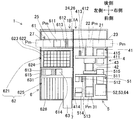
- the three-dimensional modeling machine 1 is composed of a plurality of modules, a work unit provided in each of the plurality of modules, a pallet transport unit provided in each of the plurality of modules, a shielding member 7, and the like.
- the plurality of modules correspond to the modeling module 1A on the right side and the mounting module 1B on the left side.
- the plurality of work units share the work of manufacturing the three-dimensional model on the pallet Pm.
- the plurality of pallet transfer units can carry the pallet Pm into the module, carry it out of the module, and transfer the pallet Pm to another adjacent module.
- the three-dimensional model in the process of being manufactured is transported in a state of being placed on the pallet Pm.
- the modeling module 1A includes a first pallet transfer unit 21, an internal transfer unit 31, a modeling work unit group 4 that shares the modeling work of a three-dimensional model, and a forming work unit group 5 that shares the forming work of a circuit pattern of an electronic circuit. Is provided.
- the mounting module 1B is provided with a second pallet transfer unit 25 and a mounting work unit group 6 that shares the work of mounting electronic components on the circuit pattern.
- the shielding member 7 is arranged between the modeling module 1A and the mounting module 1B.
- the shielding member 7 is arranged between two adjacent modules to suppress the influence of the working unit in one module on the other module. Specifically, the shielding member 7 suppresses at least one of the effects of heat dissipation, ventilation, and ultraviolet irradiation performed by the working unit in one module.
- the shielding member 7 is formed in a plate shape by using, for example, a material having excellent heat insulating performance and ultraviolet light shielding performance. The plate-shaped shielding member 7 can suppress the influence of air blowing regardless of the material.
- the first pallet transport unit 21 is arranged near the rear portion in the modeling module 1A and extends in the left-right direction.
- the first pallet transport unit 21 has a carry-in end 23 that opens to the right of the modeling module 1A and a carry-out end 24 that opens toward the mounting module 1B. Further, the first pallet transport section 21 has a branch section 22 in the middle.
- the first pallet transport unit 21 carries the pallet Pm into the module from the carry-in end 23 and conveys it to the branch portion 22. Further, the first pallet transport unit 21 transports the pallet Pm from the branch portion 22 to the carry-out end 24 and carries it out of the module. The area corresponding to the carry-out end 24 of the shielding member 7 is perforated, and there is no problem in carrying out the pallet Pm. Further, the first pallet transport unit 21 can also transport the pallet Pm from the carry-out end 24 to the branch portion 22 in the opposite direction.
- the internal transport unit 31 is a work unit that shares the transport work of the pallet Pm.
- the internal transport unit 31 extends forward from the branch portion 22 and passes substantially in the center of the modeling module 1A in the left-right direction.
- the internal transport unit 31 is shared by the modeling work unit group 4 and the forming work unit group 5, and transports the pallet Pm in the front-rear direction.
- the internal transport unit 31 has a pallet remounting mechanism (not shown) in the vicinity of the branch portion 22. The pallet remounting mechanism remounts the pallet Pm between the first pallet transport unit 21 and the internal transport unit 31.
- the pallet Pm is shown by a broken line at the carry-in end 23 and the branch portion 22, and the pallet Pm is shown by a solid line near the front end of the internal transport unit 31.
- the first pallet transfer unit 21 and the internal transfer unit 31 are each configured by using a conveyor device having a rotating conveyor belt.
- the first pallet transfer unit 21 and the internal transfer unit 31 may have a configuration other than the conveyor device, for example, a configuration in which the pallet Pm is gripped and moved by a robot hand.
- the modeling work unit group 4 is arranged at the rear of the modeling module 1A.
- the modeling work unit group 4 performs modeling work of a three-dimensional modeled object using modeling ink that is solidified by irradiation with ultraviolet rays.
- the modeling work unit group 4 includes a modeling ink printing unit 41, a flattening unit 42, and a curing unit 43.
- the modeling ink printing unit 41 includes a gantry 411, a modeling head 412, a modeling nozzle 413, an ink tank 414, a maintenance unit 415, and the like.
- the gantry 411 is a gate-shaped structure that straddles the internal transport unit 31.
- the horizontal portion extending in the left-right direction of the gantry 411 is arranged at a height exceeding the height dimension of the three-dimensional model with respect to the internal transport unit 31.
- the modeling head 412 is mounted on the horizontal portion of the gantry 411 and moves in the left-right direction.
- a plurality of modeling nozzles 413 are provided in a line in the front-rear direction on the lower side of the modeling head 412.
- the plurality of modeling nozzles 413 have a function of individually switching the injection and stopping of the modeling ink.
- the modeling ink is stored in the ink tank 414 arranged on the left side of the front portion of the modeling module 1A, and is supplied to the modeling nozzle 413 using a tube (not shown).
- the pallet Pm Prior to the operation of the modeling head 412 and the modeling nozzle 413, the pallet Pm is carried into the working position below the gantry 411. In conjunction with the movement of the modeling head 412 in the left-right direction, the modeling nozzle 413 performs a modeling operation that individually switches the injection and stop of the modeling ink. As a result, a layer shape of the modeling ink is formed on the pallet Pm. The layer shape matches the shape of the three-dimensional model specified in the layer data.
- the modeling operation is performed a plurality of times. More specifically, the internal transfer unit 31 operates after the first modeling operation to change the position of the pallet Pm in the front-rear direction. Next, the second modeling operation is performed, and the range of the three-dimensional modeled object that was not modeled in the first modeling operation is modeled. In this way, the modeling operation and the position change of the pallet Pm are repeated to form the entire layer shape of the three-dimensional modeled object.
- the pallet Pm having a layered shape is transported to a working position below the flattening unit 42 by the internal transport unit 31.
- the modeling head 412 and the modeling nozzle 413 may be fixed above the internal transport unit 31, and the pallet Pm may be moved in the front-rear direction by the transport of the internal transport unit 31.
- the maintenance unit 415 is provided at a position on the right side of the internal transport unit 31 and below the gantry 411.
- the modeling head 412 and the modeling nozzle 413 move to the maintenance unit 415 as needed, and receive maintenance from the maintenance unit 415.
- the maintenance contents of the maintenance unit 415 include cleaning by wiping the tip of the modeling nozzle 413 and replacement of the defective modeling nozzle 413.
- the flattening unit 42 is provided so as to be able to move up and down at a position separated forward from the gantry 411.
- the flattening unit 42 descends to the height of the layer shape on the carried-in pallet Pm to flatten the surface of the liquid layer shape.
- the height of the layer shape is made uniform and adjusted to a predetermined minute height dimension. After that, the pallet Pm is transported to the working position below the curing unit 43 by the internal transport unit 31.
- the curing unit 43 is provided at a position on the front side of the gantry 411 so as to be able to move up and down.
- the curing unit 43 descends until it approaches the layer shape on the pallet Pm carried in, and irradiates the layer shape with ultraviolet rays.
- the polymerizable compound in the modeling ink is polymerized and solidified, and the layer shape is solidified.
- the influence of the ultraviolet irradiation performed by the curing unit 43 is suppressed by the shielding member 7, and has almost no effect on the mounting module 1B. Therefore, the range requiring measures against ultraviolet irradiation is limited to the modeling module 1A, the cost increase is suppressed, and the operation reliability is improved.
- the modeling head 412, the modeling nozzle 413, the flattening unit 42, and the curing unit 43 can be repeatedly operated in order.
- the liquid layer shape is formed so as to overlap the upper side of the solid layer shape and is solidified.
- the height of the three-dimensional modeled object in the middle of modeling increases by a minute height dimension.
- the pallet Pm is transported to a position corresponding to the content of the next step.
- the forming work unit group 5 is arranged at the front part of the modeling module 1A.
- the forming work unit group 5 draws and forms a circuit pattern on a three-dimensional model using conductive ink in which metal fine particles such as silver are mixed in a solvent.
- the forming work unit group 5 includes a circuit ink printing unit 51, a drying unit 52, and a firing unit 53.
- the circuit ink printing unit 51 includes a gantry 511, a drawing head 512, an inkjet nozzle 513, a cleaning liquid tank 514, a maintenance unit 515, and the like.
- the gantry 511 is a gate-shaped structure that straddles the internal transport unit 31.
- the horizontal portion extending in the left-right direction of the gantry 511 is arranged at a height exceeding the height dimension of the three-dimensional model with respect to the internal transport unit 31.
- the drawing head 512 is mounted on the horizontal portion of the gantry 511 and moves in the left-right direction.
- a plurality of inkjet nozzles 513 are provided in a line in the front-rear direction on the lower side of the drawing head 512.
- the plurality of inkjet nozzles 513 have a function of individually switching the injection and stopping of the conductive ink.
- the drawing head 512 and the inkjet nozzle 513 move to the maintenance unit 515.
- the maintenance unit 515 is provided at a position on the right side of the internal transport unit 31 and below the gantry 511. In the maintenance unit 515, the operator performs a replenishment operation for replenishing the inkjet nozzle 513 with the conductive ink.
- the conductive ink has a relatively short usable period, so it may be discarded.
- the cleaning liquid stored in the cleaning liquid tank 514 on the front side of the ink tank 414 is supplied to the inkjet nozzle 513 using the tube shown in the drawing.
- the inside of the inkjet nozzle 513 is cleaned.
- the inkjet nozzle 513 is kept filled with the cleaning liquid, and the clean state is maintained until the next replenishment operation.
- the pallet Pm on which the three-dimensional modeled object during or after modeling is placed is carried into the working position on the lower side of the gantry 511.
- the inkjet nozzle 513 performs a drawing operation of individually switching the ejection and stopping of the conductive ink. As a result, the shape of the circuit pattern defined in the layer data is drawn.
- the drawing operation is performed a plurality of times. More specifically, after the first drawing operation, the internal transfer unit 31 operates to change the position of the pallet Pm in the front-rear direction. Next, the second drawing operation is performed, and the range of the circuit pattern that was not drawn in the first drawing operation is drawn. In this way, the drawing operation and the position change of the palette Pm are repeated, and the entire shape of the circuit pattern is drawn.
- the drawing head 512 and the inkjet nozzle 513 may be fixed above the internal transport unit 31, and the pallet Pm may be moved in the front-rear direction by the transport of the internal transport unit 31.
- the firing unit 53 is located on the right side of the internal transport unit 31 and is located in front of the circuit ink printing unit 51.
- the drying unit 52 is provided attached to the firing unit 53.
- the pallet Pm that has completed the drawing operation is conveyed to the working position on the left side of the firing unit 53 by the internal transfer unit 31.
- the firing unit 53 captures a three-dimensional model on which a circuit pattern is drawn from the pallet Pm by using a transfer hand (not shown).
- the drying unit 52 sends cold air or hot air toward the conductive ink on the three-dimensional model to evaporate a part of the solvent and dry it.
- the firing unit 53 heats the conductive ink to further evaporate the solvent and fire the circuit pattern.
- the firing unit 53 returns the three-dimensional model whose circuit pattern has been fired to the original position of the pallet Pm by using the transfer hand.
- the firing unit 53 may operate so as to take in the entire pallet Pm on which the three-dimensional model is placed and fire it. Further, the drying unit 52 and the firing unit 53 may be formed separately.
- the influence of the air blown by the drying unit 52 is suppressed by the shielding member 7, and has almost no influence on the mounting module 1B. Further, the influence of heat dissipation during heating performed by the firing unit 53 is suppressed by the shielding member 7 and has almost no influence on the mounting module 1B. Therefore, the range requiring measures against ventilation and heat dissipation is limited to the modeling module 1A, the increase in cost is suppressed, and the operation reliability is improved.
- the second pallet transport unit 25 is arranged near the rear portion in the mounting module 1B and extends in the left-right direction.
- the second pallet transport unit 25 has a carry-in end 26 that opens toward the modeling module 1A and a carry-out end 27 that opens to the left of the mounting module 1B.
- the carry-in end 26 of the second pallet transport unit 25 faces the carry-out end 24 of the first pallet transport unit 21 at a short distance, and the pallet Pm can be delivered.
- the second pallet transport unit 25 receives the pallet Pm at the carry-in end 26, carries it into the module, and transports it to a predetermined mounting implementation position. Further, the second pallet transport unit 25 can also transport the pallet Pm from the mounting implementation position to the carry-in end 26 in the opposite direction. Further, the second pallet transport unit 25 transports the pallet Pm on which the completed three-dimensional model is placed to the carry-out end 27 and carries it out of the module.
- the pallet Pm is shown by a solid line at the mounting implementation position, and the pallet Pm is shown by a broken line at the carry-out end 27.
- the second pallet transport unit 25 is configured by using a conveyor device having a rotating conveyor belt. The first pallet transfer unit 21 and the second pallet transfer unit 25 can transport different pallet Pm by operating independently.
- the mounting work unit group 6 occupies most of the mounting module 1B.
- the mounting work unit group 6 mounts electronic components on a circuit pattern formed on a three-dimensional model.
- the mounting work unit group 6 includes a component mounting unit 61, a component supply unit 62, a paste supply unit 63, and a paste curing unit 64.
- the component mounting unit 61 performs mounting work on the pallet Pm held at the mounting implementation position of the second pallet transport unit 25.
- the component mounting unit 61 includes a mobile gantry 611, a mounting head 612, a component camera 614, a mounting tool station 615, and the like.
- the mobile gantry 611 is a gate-type mobile device that can move in the front-rear direction.
- the moving gantry 611 passes above the second pallet transport section 25 and moves from the substantially front end to the rear end of the mounting module 1B.
- the mounting head 612 is provided on the moving gantry 611 and moves in the left-right direction.
- the mounting head 612 replaceably holds one or more component mounting tools 613 below it.
- the component mounting tool 613 collects electronic components from the component supply unit 62 and mounts them on the circuit pattern.
- the plurality of component mounters 613 may be arranged on a straight line or on a circumference as shown in FIG. Examples of the component mounting tool 613 include a suction nozzle and a holding type mounting tool.
- the parts camera 614 is arranged near the center of the mounting module 1B.
- the component camera 614 captures a situation in which the component mounting tool 613 of the mounting head 612 is collecting electronic parts from below, and acquires image data.
- the acquired image data is image-processed to determine the presence / absence of electronic components and correctness, and also to determine the collected posture. These determination results are reflected in the mounting work of electronic components.
- the fixture station 615 is located on the left side of the parts camera 614.
- the mounting tool station 615 temporarily stores a plurality of types of component mounting tools 613 that can be used properly according to the size of electronic components and the like.
- the fitting station 615 further temporarily stores a coating tool 631 (described in detail later) for applying a paste-like conductive material.
- the mounting head 612 can move above the mounting tool station 615 to automatically replace the component mounting tool 613 and the coating tool 631 to be held.
- the parts supply unit 62 includes a tray type parts supply unit 621 and a feeder type parts supply unit 625.
- the tray-type component supply unit 621 is arranged on the front side of the second pallet transport unit 25.
- the tray-type component supply unit 621 supplies electronic components using a tray 622 that holds a plurality of electronic components.
- the plurality of trays 622 are mounted on the component pallets 623.
- the component pallet 623 is carried in from the carry-in outlet 624 which opens on the left side surface of the mounting module 1B.
- a pallet transfer device that automatically carries in and out the component pallet 623 may be attached.
- the feeder type parts supply unit 625 is arranged on the left side of the front part of the mounting module 1B.
- the feeder type component supply unit 625 is configured by arranging a plurality of feeder devices 626. Each feeder device 626 sends out a carrier tape that holds a plurality of electronic components to supply the electronic components.
- the paste supply unit 63 is arranged side by side with the feeder type component supply unit 625 on the right side of the front portion of the mounting module 1B.
- the paste supply unit 63 supplies a paste-like conductive material that electrically and mechanically connects the component mounting position of the circuit pattern and the connection portion (electrode or lead) of the electronic component.
- the "paste-like conductive material” is abbreviated as "paste”.
- a silver paste or a conductive adhesive having a viscosity higher than that of the conductive ink is used, and in addition, molten solder may be used.
- the paste supply unit 63 is pulled forward to replenish, maintain, and adjust the paste.
- the paste application work includes a first application method of applying to the component mounting position of the circuit pattern and a second application method of applying to the connection portion of the electronic component.
- the coating tool 631 for applying the paste is held by the mounting head 612. That is, the mounting head 612 replaceably holds the coating tool 631 and the component mounting tool 613, or holds both the coating tool 631 and the component mounting tool 613.
- the second coating method the coating tool 631 is not used.
- the mounting head 612 plays a dual role of a paste coating operation and an electronic component mounting operation.
- the pallet Pm on which the three-dimensional model having the circuit pattern already formed is placed is carried into the mounting implementation position.
- the mounting head 612 first moves above the paste supply unit 63 while holding the coating tool 631. Next, the mounting head 612 lowers the coating tool 631 and immerses the lower portion thereof in the paste to attach the paste.
- the mounting head 612 moves above the component camera 614.
- the component camera 614 captures the coating tool 631 from below to acquire image data.
- the acquired image data is image-processed to determine whether or not the paste adheres. If the adhesion state is poor, the mounting head 612 moves again above the paste supply unit 63 to perform a retry operation.
- the mounting head 612 moves above the three-dimensional modeled object at the mounting implementation position. Next, the mounting head 612 lowers the coating tool 631 and applies the paste adhering to the lower portion to the component mounting position of the circuit pattern. This completes the first coating method of the paste.
- the transfer pin can be exemplified as the coating tool 631, and is not limited thereto.
- the transfer pin has a transfer surface at the tip that imitates the shape and area to be applied to the circuit pattern.
- the number of transfer surfaces included in the transfer pin may be only one, or may be a plurality of separated transfer surfaces.
- the mounting head 612 moves to at least one of the tray-type component supply unit 621 and the feeder-type component supply unit 625 while holding the component mounting tool 613.
- the mounting head 612 lowers the component mounting tool 613 to collect electronic components from at least one of the tray-type component supply unit 621 and the feeder-type component supply unit 625.
- the mounting head 612 moves above the component camera 614.
- the component camera 614 captures a state in which the component mounting tool 613 is collecting electronic components from below, and acquires image data.
- the acquired image data is image-processed to determine the presence / absence of electronic components, correctness, and collection posture.
- the mounting head 612 disposes of the electronic component determined to be defective. When it is determined to be good, the mounting head 612 moves above the three-dimensional modeled object at the mounting execution position. Next, the mounting head 612 lowers the component mounting tool 613 to mount the electronic component on the paste on the circuit pattern. This completes the work of mounting the electronic components.
- the mounting head 612 that holds the plurality of component mounting tools 613 can mount electronic components equal to the number of component mounting tools 613 in a single mounting operation. Further, the paste application work and the electronic component mounting work are repeated in a plurality of cycles as needed.
- the mounting head 612 moves to at least one of the tray type component supply unit 621 and the feeder type component supply unit 625 while holding the component mounting tool 613.
- the mounting head 612 lowers the component mounting tool 613 to collect electronic components from at least one of the tray-type component supply unit 621 and the feeder-type component supply unit 625.
- the mounting head 612 moves above the paste supply unit 63.
- the mounting head 612 lowers the component mounting tool 613 to immerse the connection portion of the electronic component being collected in the paste. As a result, the paste is applied to the connection portion.
- the mounting head 612 which holds the plurality of component mounting tools 613, lowers the component mounting tools 613 one by one to perform the coating operation.
- the mounting head 612 moves above the component camera 614.
- the component camera 614 captures an image of the electronic component collected on the component mounting tool 613 from below to acquire image data.
- the acquired image data is image-processed to determine the collection posture of the electronic component and the quality of the paste adhesion state.
- the mounting head 612 performs a retry operation or a disposal operation of the electronic component determined to be defective. When it is determined to be good, the mounting head 612 moves above the three-dimensional modeled object at the mounting execution position. Next, the mounting head 612 lowers the component mounting tool 613 to mount the paste-coated electronic component on the circuit pattern. This completes the work of mounting the electronic component using the second coating method of the paste.
- the paste curing unit 64 heats and cures the paste to ensure the mounting state of the electronic components.
- the firing unit 53 of the modeling module 1A also functions as the paste curing unit 64. That is, the pallet Pm for which the electronic component mounting work has been completed is conveyed to the firing unit 53 to cure the paste.
- the present invention is not limited to this, and a separate paste curing unit 64 may be provided in the mounting module 1B.
- Ring sensor 9 as an example of three-dimensional model Fr
- One or more three-dimensional shaped objects Fr are manufactured on the pallet Pm.
- nine three-dimensional shaped objects Fr are arranged in 3 ⁇ 3 on the pallet Pm and manufactured at one time.
- the nine modeled objects Fr may be all the same product, partly the same product, or all have different shapes. Therefore, the three-dimensional modeling machine 1 is suitable for applications such as high-mix batch production and simultaneous production of a plurality of prototypes having slightly different designs.
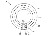
- the ring-shaped sensor 9 is composed of a ring-shaped base 91 having a hollow portion 92 and an electronic circuit 95 provided in the base 91.
- the cross section of the base 91 orthogonal to the circumferential direction is rectangular, but the cross section is not limited to this and may be circular.
- a part of the base portion 91 in the circumferential direction is a circuit exposed portion 93, with the thickness of the upper half being omitted.
- the electronic circuit 95 is composed of a circuit pattern 96 and two electronic components connected to the circuit pattern 96.
- the circuit pattern 96 is embedded in the intermediate height of the base 91 and is exposed in the circuit exposed portion 93.
- the circuit pattern 96 comprises two concentric wires along the circumferential direction of the base 91. Strictly speaking, the circuit pattern 96 consists of two arc-shaped wires having a central angle slightly smaller than 360 ° and having both ends at the position of the circuit exposed portion 93. A total of four ends of the circuit pattern 96 are component mounting positions 97.
- the electronic component consists of a detection component 98 and a battery 9A.
- the detection component 98 is connected to the upper side of the four component mounting positions 97 of the circuit pattern 96.
- the detection component 98 detects the magnitude of the magnetic field interlinking with the ring-shaped circuit pattern 96 by utilizing the electromagnetic induction action.
- the detection component 98 has a quadrangular plate-like outer shape and has a pair of output terminals 99. By arranging the detection component 98 in the circuit exposed portion 93, the output signal of the output terminal 99 can be taken out to the outside by using the output line.
- the battery 9A is mounted at a position close to the detection component 98.
- the battery 9A is directly connected to a power supply terminal (not shown) of the detection component 98 to supply power to the detection component 98.
- a power supply terminal not shown
- the battery 9A can be replaced when it is consumed.
- the detection component 98 and the battery 9A are supplied from the tray 622 of the tray-type component supply unit 621.
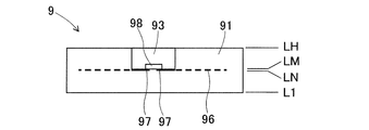
- the control device holds the three-dimensional shape data of the ring-shaped sensor 9.
- the three-dimensional shape data includes the lowermost first layer data L1 shown in FIG. 4 to the uppermost uppermost layer data LH.
- the data will be described in order from the lower layer data.
- the first layer data L1 to the first (N-1) layer data are the same as each other, and represent a ring-shaped planar cross-sectional shape without the circuit exposed portion 93 of the base 91.
- the Nth layer data LN to the (M-1) layer data are the same as each other, and represent a C-shaped horizontal cross-sectional shape having the circuit exposed portion 93 of the base 91 and the shape of the embedded circuit pattern 96.
- the M-layer data LM represents a component mounting position 97 for mounting the detection component 98 and the battery 9A, in addition to the C-shaped horizontal cross-sectional shape having the circuit exposed portion 93 of the base 91.
- the first (M + 1) layer data to the uppermost layer data LH are the same as each other, and represent a C-shaped horizontal cross-sectional shape in which the circuit exposed portion 93 of the base 91 is present.
- the manufacturing process diagram shown in FIG. 5 comprises 6 steps from the first step K1 to the sixth step K6. This manufacturing process diagram is executed by control from the control device.
- the first pallet transport unit 21 carries in the pallet Pm from the carry-in end 23.
- the control device refers to the lower layer data in order, and controls so as to repeat the second step K2 to the fifth step K5 for each layer data. It should be noted that not all of the second step K2, the third step K3, and the fourth step K4 are executed in the repetition. In practice, only one or two steps are often performed.
- the modeling work unit group 4 operates to model the ring-shaped sensor 9 on the pallet Pm in small height dimensions.
- the forming work unit group 5 operates to form the circuit pattern 96 on the ring-shaped sensor 9 in the middle of modeling.
- the mounting work unit group 6 operates to mount the detection component 98 and the battery 9A at the component mounting position 97 of the circuit pattern 96.
- the control device determines whether or not the control for referring to the uppermost layer data LH has been completed. If not finished, the control device advances the referenced layer data by one upward and returns the control execution to the second step K2. When the control for referring to the uppermost layer data LH is completed and the production of the ring-shaped sensor 9 is completed, the control device advances the execution of the control to the sixth step K6.
- the second pallet transport unit 25 carries out the ring-shaped sensor 9 together with the pallet Pm from the carry-out end 27. This completes one cycle of manufacturing the ring-shaped sensor 9.
- the second step K2 is repeatedly executed while the first layer data L1 to the (N-1) layer data are referred to. Further, while the Nth layer data LN refers to the (M-1) layer data, the second step K2 and the third step K3 are repeatedly executed. By repeating this process, the circuit pattern 96 is formed inside the base 91. Further, when the third layer data LM is referred to, the second step K2 and the fourth step K4 are executed. By this fourth step K4, the detection component 98 and the battery 9A are mounted at the component mounting position 97 on the circuit pattern 96.
- the second step K2 is repeatedly executed. As a result, the substantially upper half of the base 91 having the circuit exposed portion 93 is formed, and the circuit pattern 96 is embedded.
- the ring-shaped sensor 9 is completed by the above manufacturing process.
- Patent Document 1 In the conventional three-dimensional modeling machine exemplified in Patent Document 1, it is not possible to use a plurality of pallets Pm at the same time and perform a plurality of operations in parallel, and it is difficult to improve the manufacturing efficiency. Further, in the prior art, there is a problem that the members cannot be replenished or maintained because it is unknown when the pallet Pm arrives in the work unit whose operation is interrupted during operation.
- the first pallet transport unit 21 and the second pallet transport unit 25 operate independently and transport different pallet Pm. Therefore, the work unit of the modeling module 1A and the work unit of the mounting module 1B can perform the work on two different pallets Pm in parallel. As a result, the manufacturing efficiency of the three-dimensional modeling machine 1 is higher than before.
- the pallet remounting mechanism arranged in the vicinity of the branch portion 22 swaps the positions of the two pallets Pm as needed to enable parallel work to be executed.
- the modeling module 1A and the mounting module 1B can be individually switched between operation and stop. Therefore, when one module is in operation, the other module can be stopped to replenish or maintain members.
- the mounting module 1B can be stopped to replace the tray 622 and the feeder device 626, and the paste supply unit 63 can replenish and maintain the paste.
- the mounting module 1B is stopped, the maintenance unit 515 of the circuit ink printing unit 51 performs ink replenishment work and cleaning work of the inkjet nozzle 513, and the ink tank 414 is replenished with modeling ink. Or, the cleaning liquid tank 514 can be replenished with the cleaning liquid.
- one of the modeling module 1A and the mounting module 1B is configured so that it can be moved separately from the other. As a result, maintenance such as replacement in module units and detailed inspection in module units becomes possible.
- the transport tool since the modules can be separated and transported, the transport tool may be simple, and the transport work and the installation work can be facilitated.
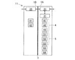
- the three-dimensional modeling machine 1 is represented by the block diagram of FIG.
- the bidirectional arrows represent the transportation of the pallet Pm.
- the modeling module 1A is provided with nine block elements, that is, a first pallet transfer unit 21, an internal transfer unit 31, and seven work units. Specific names of the working unit are a modeling ink printing unit 41, a flattening unit 42, a curing unit 43, a circuit ink printing unit 51, a drying unit 52, a firing unit 53, and a paste curing unit 64.
- the mounting module 1B is provided with four block elements, that is, a second pallet transfer unit 25, a component mounting unit 61, a component supply unit 62, and a paste supply unit 63.
- the block diagram of FIG. 6 can be transformed into the block diagram of the three-dimensional modeling machine 11 in the modified form shown in FIG. 7.
- the paste supply unit 63 has been moved from the mounting module 1B to the modeling module 1A, and the other block elements are unchanged.
- the forming work unit group 5 and the paste supply unit 63 are provided in the same module. Therefore, immediately after the forming work unit group 5 forms the circuit pattern, the paste supply unit 63 can form a pad (an electrode for mounting an electronic component) on the circuit pattern by using the paste. At this time, the transport operation of the pallet Pm is reduced, so that the manufacturing efficiency is improved.
- the first pallet transfer unit 21 provided in the modeling module 1A and the second pallet transfer unit 25 provided in the mounting module 1B are pallet Pm.
- the transport operation is shared. Therefore, it is possible to reduce the size of the plurality of pallet transport units as compared with the conventional drive device for freely moving the pallet Pm in the three-dimensional modeling machine. As a result, the three-dimensional modeling machine 1 can be downsized.
- the number of modules is not increased meaninglessly to two, and a plurality of work units are compactly arranged in the modules, which also contributes to miniaturization.
- the three-dimensional modeling machine 81 and the modified form of the second embodiment Next, the second embodiment and the modified form thereof will be described with reference to the block diagrams of FIGS. 8 and 9. As shown in FIG. 8, in the three-dimensional modeling machine 81 of the second embodiment, the modeling module 1A, the heating module 1C, and the mounting module 1B are arranged adjacent to each other in the order described.
- the modeling module 1A is provided with a first pallet transfer unit 21, an internal transfer unit 31, a modeling ink printing unit 41, a flattening unit 42, a curing unit 43, a circuit ink printing unit 51, a drying unit 52, and a paste supply unit 63. ..
- the heating module 1C is provided with a second pallet transfer unit 25, a firing unit 53, and a paste curing unit 64.
- the heating module 1C is a module provided only with a work unit having a large influence on others in the shared work, and specifically, a module provided with only a work unit that dissipates heat in the work.
- the mounting module 1B is provided with a second pallet transfer unit 25, a component mounting unit 61, and a component supply unit 62.
- the shielding member 71 between the modeling module 1A and the heating module 1C is excellent in heat insulating performance and light shielding performance.
- the shielding member 72 between the heating module 1C and the mounting module 1B has excellent heat insulating performance.
- the working units that dissipate heat are grouped in the heating module 1C. Therefore, it is not necessary to take measures against heat dissipation in the modeling module 1A and the mounting module 1B. Further, the heating module 1C and the mounting module 1B do not require measures against ultraviolet irradiation. As a result, the increase in cost is suppressed and the operation reliability is improved.
- the block diagram of FIG. 8 can be transformed into a block diagram of the three-dimensional modeling machine 82 in the modified form shown in FIG.
- the paste supply unit 63 has been moved from the modeling module 1A to the mounting module 1B, and the other block elements and shielding members (71, 72) are unchanged.
- the arrangement of the paste supply unit 63 is appropriately changed depending on the target to which the paste is supplied.
- the increase in cost is suppressed and the operation reliability is improved.
- the modeling module 1A is provided with a first pallet transfer unit 21, an internal transfer unit 31, a modeling ink printing unit 41, a flattening unit 42, a curing unit 43, a circuit ink printing unit 51, and a drying unit 52.
- the internal configurations of the heating module 1C and the mounting module 1B are the same as those in the second embodiment.
- the paste supply module 1D is provided with a second pallet transfer unit 25 and a paste supply unit 63.
- the shielding member 71 between the modeling module 1A and the heating module 1C is excellent in heat insulating performance and light shielding performance.
- the shielding member 72 between the heating module 1C and the paste supply module 1D has excellent heat insulating performance.
- the working units that dissipate heat are grouped in the heating module 1C. Therefore, it is not necessary to take measures against heat dissipation in the three modules other than the heating module 1C. Further, the three modules other than the modeling module 1A do not require measures against ultraviolet irradiation. As a result, the increase in cost is suppressed and the operation reliability is improved.
- the paste supply unit 63 is separated from the modeling module 1A of the second embodiment, and is provided as a single working unit in the paste supply module 1D of the third embodiment. ..
- the paste supply unit 63 performs the work of supplying the paste to the connection portion of the electronic component and the work of forming the pad by using the paste in the circuit pattern, the number of times of the work is large and the time required for the work is large. Is long.
- the other working units in the modeling module 1A cannot perform the work for a long time when the paste supply unit 63 works. That is, the paste supply unit 63 becomes a bottleneck in the manufacturing process.
- the three-dimensional modeling machine 83 of the third embodiment has higher manufacturing efficiency than that of the second embodiment.
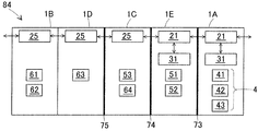
- the modeling module 1A, the forming module 1E, the heating module 1C, the paste supply module 1D, and the mounting module 1B are adjacent to each other in the order described. Be placed.
- the modeling module 1A is provided with a first pallet transfer unit 21, an internal transfer unit 31, a modeling ink printing unit 41, a flattening unit 42, and a curing unit 43.
- the forming module 1E is provided with a first pallet transfer unit 21, an internal transfer unit 31, a circuit ink printing unit 51, and a drying unit 52.
- the internal configurations of the heating module 1C, the paste supply module 1D, and the mounting module 1B are the same as those in the third embodiment.
- the shielding member 73 between the modeling module 1A and the forming module 1E is excellent in light shielding performance.
- the shielding member 74 between the forming module 1E and the heating module 1C is excellent in heat insulating performance.
- the shielding member 75 between the heating module 1C and the paste supply module 1D has excellent heat insulating performance.
- the working units that dissipate heat are grouped in the heating module 1C. Therefore, it is not necessary to take measures against heat dissipation in the four modules other than the heating module 1C. Further, the four modules other than the modeling module 1A do not require measures against ultraviolet irradiation. As a result, the increase in cost is suppressed and the operation reliability is improved.
- the modeling module 1A of the third embodiment is functionally divided into the modeling module 1A and the forming module 1E of the fourth embodiment. Therefore, the work unit in the modeling module 1A and the work unit in the forming module 1E can work on different pallets Pm, respectively.
- the paste supply module 1D does not become a bottleneck in the manufacturing process as in the third embodiment. Therefore, the three-dimensional modeling machine 84 of the fourth embodiment has higher manufacturing efficiency than the third embodiment.
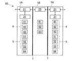
- the modeling module 1A, the mounting module 1B, and the modeling module 1A are arranged adjacent to each other in the order described.
- the second modeling module 1A is added to the module configuration of the first embodiment.
- the arrangement of the modules is symmetrical, and the pallets Pm are carried into the modeling module 1A from both the left and right sides and carried out to both the left and right sides.
- the time required for the work in the mounting module 1B is less than half the time required for the work in the modeling module 1A. Therefore, the work unit in the mounting module 1B can work on the pallets Pm alternately carried in from the modeling modules 1A on both sides without delay.
- the three-dimensional modeling machine 84 of the fifth embodiment has two modeling modules 1A that require a long time to work on the work unit in the module, and one mounting module that requires a short time to work on the work unit in the module. It has 1B.
- the three-dimensional modeling machine 84 of the fifth embodiment has substantially twice the manufacturing capacity of the three-dimensional modeling machine 1 of the first embodiment even if it does not include the second mounting module 1B, so that the equipment cost is reduced. It is advantageous in terms of.
- the modeling module 1A does not have the internal transfer unit 31, and the modeling work unit group 4 and the forming work unit group 5 are arranged along the first pallet transfer unit 21. You may be. Further, the drying unit 52 may be omitted, and the firing unit 53 may dry and fire the circuit pattern. Further, the component supply unit 62 of the mounting module 1B may be composed of only one of the tray-type component supply unit 621 and the feeder-type component supply unit 625. Further, an internal configuration of modules other than those described in each embodiment or a combination of modules other than those described may be adopted.
- the modeling work by the modeling work unit group 4 a method other than the combination of the modeling ink and the ultraviolet irradiation described in the first embodiment may be used. Further, for the forming work by the forming work unit group 5, a method other than drawing by the drawing head 512 and the inkjet nozzle 513 may be used.
- the first to fifth embodiments can be applied and modified in various ways.
- Modeling module 1B Mounting module 1C: Heating module 1D: Paste supply module 1E: Formation module 21: 1st pallet transfer section 22: Branch section 25: 2nd pallet transfer section 31: Internal Transport unit 4: Modeling work unit group 41: Modeling ink printing unit 42: Flattening unit 43: Curing unit 5: Forming work unit group 51: Circuit ink printing unit 52: Drying unit 53: Baking unit 6: Mounting work unit group 61 : Parts mounting unit 62: Parts supply unit 63: Paste supply unit 64: Paste curing unit 7, 71 to 75: Shielding member 81 to 85: Three-dimensional modeling machine 9: Ring sensor 95: Electronic circuit 96: Circuit pattern 98: Detection Parts 9A: Battery Fr: Three-dimensional model Pm: Pallet
Landscapes
- Engineering & Computer Science (AREA)
- Manufacturing & Machinery (AREA)
- Microelectronics & Electronic Packaging (AREA)
- Chemical & Material Sciences (AREA)
- Materials Engineering (AREA)
- Physics & Mathematics (AREA)
- Mechanical Engineering (AREA)
- Optics & Photonics (AREA)
- Supply And Installment Of Electrical Components (AREA)
- Electric Connection Of Electric Components To Printed Circuits (AREA)
- Manufacturing Of Printed Wiring (AREA)
Abstract
Description
まず、第1実施形態の三次元造形機1の全体構成について、図1を参考にして説明する。図1の右上の矢印に示されるように、三次元造形機1の前後左右を便宜的に定める。三次元造形機1は、電子回路を有する三次元造形物を製造する。三次元造形物の形状は、三次元形状データによって規定される。三次元形状データは、所定の微小高さ寸法のピッチで形状を規定する二次元の層データの複数個からなる。
次に、造形モジュール1Aの内部構成について詳述する。第1パレット搬送部21は、造形モジュール1A内の後部寄りに配置され、左右方向に延在する。第1パレット搬送部21は、造形モジュール1Aの右方に開口する搬入端23、および装着モジュール1Bに向かって開口する搬出端24を有する。さらに、第1パレット搬送部21は、途中に分岐部22を有する。
次に、装着モジュール1Bの内部構成について詳述する。第2パレット搬送部25は、装着モジュール1B内の後部寄りに配置され、左右方向に延在する。第2パレット搬送部25は、造形モジュール1Aに向かって開口する搬入端26、および装着モジュール1Bの左方に開口する搬出端27を有する。第2パレット搬送部25の搬入端26は、第1パレット搬送部21の搬出端24に近距離で対向しており、パレットPmの受け渡しが可能となっている。
次に、三次元造形物Frの一例について説明する。パレットPmの上には、1個または複数個の三次元造形物Frが製造される。図2に示される配置例において、9個の三次元造形物Frは、パレットPm上に3×3に配置され、一度に製造される。9個の造形物Frは、全部が同一品でも、一部が同一品でも、全部が相異する形状でもよい。したがって、三次元造形機1は、多品種一括生産や、少しだけ設計が相違する複数の試作品の同時生産などの用途に適する。
次に、三次元造形機1が環形センサ9を製造する場合の動作について、図5を参考にして説明する。図5に示された製造工程図は、第1工程K1から第6工程K6までの6工程からなる。この製造工程図は、制御装置からの制御によって実行される。
次に、三次元造形機1の機能構成に着目すると、三次元造形機1は、図6のブロック図によって表される。なお、図6~図12において、双方向の矢印は、パレットPmの搬送を表す。図6に示されるように、造形モジュール1Aは、9個のブロック要素、すなわち第1パレット搬送部21、内部搬送ユニット31、および7個の作業ユニットが設けられる。作業ユニットの具体名は、造形インク印刷ユニット41、平坦化ユニット42、硬化ユニット43、回路インク印刷ユニット51、乾燥ユニット52、焼成ユニット53、およびペースト硬化ユニット64である。また、装着モジュール1Bは、4個のブロック要素、すなわち第2パレット搬送部25、部品装着ユニット61、部品供給ユニット62、およびペースト供給ユニット63が設けられる。
次に、第2実施形態およびその変形形態について、図8および図9のブロック図を参考にして説明する。図8に示されるように、第2実施形態の三次元造形機81は、造形モジュール1A、加熱モジュール1C、および装着モジュール1Bが記載順に隣接して配置される。
次に、第3~第5実施形態の三次元造形機(83、84、85)について、図10~図12のブロック図を参考にして説明する。図10に示されるように、第3実施形態の三次元造形機83は、造形モジュール1A、加熱モジュール1C、ペースト供給モジュール1D、および装着モジュール1Bが記載順に隣接して配置される。
なお、第1実施形態において、造形モジュール1Aが内部搬送ユニット31を有さず、第1パレット搬送部21に沿って造形作業ユニット群4および形成作業ユニット群5が配置されていてもよい。また、乾燥ユニット52が省略されて、焼成ユニット53が回路パターンの乾燥および焼成を行ってもよい。また、装着モジュール1Bの部品供給ユニット62は、トレイ式部品供給ユニット621およびフィーダ式部品供給ユニット625の一方だけで構成されてもよい。さらに、各実施形態で説明した以外のモジュールの内部構成や、説明した以外のモジュールの組み合わせが採用されてもよい。
Claims (15)
- 電子回路を有する三次元造形物を製造する三次元造形機であって、
隣接して配置される複数のモジュールと、
複数の前記モジュールの各々に設けられ、パレットの上に前記三次元造形物を製造する作業を分担する作業ユニットと、
複数の前記モジュールの各々に設けられ、前記パレットを前記モジュール内に搬入し、および前記モジュール外に搬出し、かつ、前記パレットを隣接する別の前記モジュールとの間で受け渡し可能とするパレット搬送部と、
を備える三次元造形機。 - 前記三次元造形物の造形作業を分担する前記作業ユニット、前記電子回路の回路パターンの形成作業を分担する前記作業ユニット、および、前記回路パターンへの電子部品の装着作業を分担する前記作業ユニットを備える、請求項1に記載の三次元造形機。
- 少なくとも一つの前記作業ユニットは、前記パレット搬送部に保持されている前記パレットに対して前記作業を実施する、請求項1または2に記載の三次元造形機。
- 少なくとも一つの前記作業ユニットは、前記モジュール内において前記パレットを前記パレット搬送部と別の前記作業ユニットの間で搬送する内部搬送ユニットである、請求項1~3のいずれか一項に記載の三次元造形機。
- 複数の前記モジュールの各々に設けられた複数の前記パレット搬送部は、独立して動作することにより異なる前記パレットを搬送し、かつ、
複数の前記モジュールの各々に設けられた複数の前記作業ユニットは、異なる前記パレットに対して前記作業を実施する、
請求項1~4のいずれか一項に記載の三次元造形機。 - 個別に稼働および停止の切り替えが可能な複数の前記モジュールを備える、請求項1~5のいずれか一項に記載の三次元造形機。
- 他の前記モジュールから切り離して移動されることにより、交換およびメンテナンスの少なくとも一方が行われる前記モジュールを備える、請求項1~6のいずれか一項に記載の三次元造形機。
- 隣接する二つの前記モジュールの間に配置され、一方の前記モジュール内の前記作業ユニットが他方の前記モジュールに及ぼす影響を抑制する遮蔽部材をさらに備える、請求項1~7のいずれか一項に記載の三次元造形機。
- 前記遮蔽部材は、一方の前記モジュール内の前記作業ユニットが行う熱放散、送風、および紫外線照射の少なくともひとつの影響を抑制する、請求項8に記載の三次元造形機。
- 全ての前記作業ユニットが分けて設けられた二つの前記モジュールを備える、請求項1~9のいずれか一項に記載の三次元造形機。
- 前記三次元造形物の造形作業を分担する前記作業ユニット、および前記電子回路の回路パターンの形成作業を分担する前記作業ユニットが設けられた造形モジュールと、
前記回路パターンへの電子部品の装着作業を分担する前記作業ユニットが設けられた装着モジュールと、を備える、
請求項10に記載の三次元造形機。 - 前記作業の回数が多いかまたは所要時間が長い前記作業ユニットのみが設けられた前記モジュールを備える、請求項1~9のいずれか一項に記載の三次元造形機。
- 前記作業の回数が多いかまたは所要時間が長い前記作業ユニットがそれぞれ設けられた複数の前記モジュールを備える、請求項1~9のいずれか一項に記載の三次元造形機。
- 分担した前記作業で他に及ぼす影響度が大きな前記作業ユニットのみが設けられた前記モジュールを備える、請求項1~9のいずれか一項に記載の三次元造形機。
- 前記作業で熱放散を行う前記作業ユニットのみが設けられた前記モジュールを備える、請求項14に記載の三次元造形機。
Priority Applications (3)
| Application Number | Priority Date | Filing Date | Title |
|---|---|---|---|
| JP2021532666A JP7309878B2 (ja) | 2019-07-16 | 2019-11-13 | 三次元造形機 |
| EP19937374.7A EP4000930A4 (en) | 2019-07-16 | 2019-11-13 | MACHINE FOR THREE-DIMENSIONAL SHAPING |
| US17/626,430 US12245378B2 (en) | 2019-07-16 | 2019-11-13 | Three-dimensional molding machine |
Applications Claiming Priority (2)
| Application Number | Priority Date | Filing Date | Title |
|---|---|---|---|
| JPPCT/JP2019/027961 | 2019-07-16 | ||
| PCT/JP2019/027961 WO2021009854A1 (ja) | 2019-07-16 | 2019-07-16 | 三次元造形機、および部品装着機 |
Publications (1)
| Publication Number | Publication Date |
|---|---|
| WO2021009940A1 true WO2021009940A1 (ja) | 2021-01-21 |
Family
ID=74209740
Family Applications (2)
| Application Number | Title | Priority Date | Filing Date |
|---|---|---|---|
| PCT/JP2019/027961 Ceased WO2021009854A1 (ja) | 2019-07-16 | 2019-07-16 | 三次元造形機、および部品装着機 |
| PCT/JP2019/044592 Ceased WO2021009940A1 (ja) | 2019-07-16 | 2019-11-13 | 三次元造形機 |
Family Applications Before (1)
| Application Number | Title | Priority Date | Filing Date |
|---|---|---|---|
| PCT/JP2019/027961 Ceased WO2021009854A1 (ja) | 2019-07-16 | 2019-07-16 | 三次元造形機、および部品装着機 |
Country Status (4)
| Country | Link |
|---|---|
| US (2) | US12520464B2 (ja) |
| EP (2) | EP4002962B1 (ja) |
| JP (2) | JP7434323B2 (ja) |
| WO (2) | WO2021009854A1 (ja) |
Families Citing this family (3)
| Publication number | Priority date | Publication date | Assignee | Title |
|---|---|---|---|---|
| US11943871B2 (en) * | 2019-02-14 | 2024-03-26 | Fuji Corporation | Component mounter |
| US12520464B2 (en) * | 2019-07-16 | 2026-01-06 | Fjui Corporation | Three-dimensional molding machine and component mounting machine |
| CN112959664A (zh) * | 2021-02-01 | 2021-06-15 | 江西炫智教育科技有限公司 | 一种针对双头三维打印机的溶解取模辅助装置 |
Citations (8)
| Publication number | Priority date | Publication date | Assignee | Title |
|---|---|---|---|---|
| JPS643785B2 (ja) | 1981-10-15 | 1989-01-23 | Dainippon Printing Co Ltd | |
| JP2006066811A (ja) * | 2004-08-30 | 2006-03-09 | Toshiba Corp | はんだ印刷用マスク、部品実装方法 |
| JP2010147267A (ja) * | 2008-12-19 | 2010-07-01 | Renesas Technology Corp | 半導体集積回路装置および半導体集積回路装置の製造方法 |
| WO2016042657A1 (ja) * | 2014-09-19 | 2016-03-24 | 富士機械製造株式会社 | 製造装置及び製造方法 |
| US20170042034A1 (en) * | 2014-04-21 | 2017-02-09 | Cornell University | System and methods for additive manufacturing of electromechanical assemblies |
| JP2017130553A (ja) * | 2016-01-20 | 2017-07-27 | 株式会社ミマキエンジニアリング | 電子素子設置基材の製造方法、電子部材の製造方法、及び造形装置 |
| WO2019102522A1 (ja) * | 2017-11-21 | 2019-05-31 | 株式会社Fuji | 3次元積層電子デバイスの製造方法及び3次元積層電子デバイス |
| JP2019110254A (ja) * | 2017-12-20 | 2019-07-04 | 株式会社Fuji | 基板生産ラインおよび情報管理装置 |
Family Cites Families (21)
| Publication number | Priority date | Publication date | Assignee | Title |
|---|---|---|---|---|
| AU2287001A (en) | 1999-12-21 | 2001-07-03 | Speedline Technologies, Inc. | High speed electronic assembly system and method |
| JP2005322702A (ja) | 2004-05-07 | 2005-11-17 | Matsushita Electric Ind Co Ltd | メンテナンス装置 |
| JP5008579B2 (ja) | 2008-01-29 | 2012-08-22 | 富士機械製造株式会社 | 電子部品の実装方法、装置及びライン |
| JP4883071B2 (ja) * | 2008-10-03 | 2012-02-22 | パナソニック株式会社 | 電子部品実装システム |
| US8419404B2 (en) * | 2010-02-05 | 2013-04-16 | Asm Technology Singapore Pte Ltd | Modular molding assembly for electronic devices |
| JP5675013B2 (ja) * | 2010-06-10 | 2015-02-25 | 富士機械製造株式会社 | 電子回路組立方法および電子回路組立システム |
| JP5843551B2 (ja) * | 2011-09-30 | 2016-01-13 | 富士機械製造株式会社 | マルチディスペンサ装置 |
| JP6111092B2 (ja) * | 2013-03-06 | 2017-04-05 | ヤマハ発動機株式会社 | 電子部品実装装置の部品供給方法および電子部品実装装置用部品供給装置 |
| JP2015084388A (ja) * | 2013-10-25 | 2015-04-30 | シャープ株式会社 | 搭載部品収納治具、マルチ部品実装装置およびマルチ部品実装方法 |
| JP6272346B2 (ja) | 2013-11-07 | 2018-01-31 | 富士機械製造株式会社 | 対基板作業装置および対基板作業ライン |
| JP2017101933A (ja) | 2015-11-30 | 2017-06-08 | セイコーエプソン株式会社 | 電子部品搬送装置および電子部品検査装置 |
| JP6512448B2 (ja) * | 2015-11-30 | 2019-05-15 | 清水建設株式会社 | 建物の応答推定方法 |
| WO2017141377A1 (ja) * | 2016-02-17 | 2017-08-24 | 富士機械製造株式会社 | 作業装置および生産ライン |
| DE102016104677A1 (de) * | 2016-03-14 | 2017-09-14 | Cl Schutzrechtsverwaltungs Gmbh | Anlage zur additiven Herstellung dreidimensionaler Objekte |
| DE102016221821A1 (de) * | 2016-11-08 | 2018-05-09 | Robert Bosch Gmbh | Verfahren und Vorrichtung zur additiven Fertigung eines dreidimensionalen Werkstücks |
| WO2018134873A1 (ja) * | 2017-01-17 | 2018-07-26 | ヤマハ発動機株式会社 | 被実装物作業装置 |
| JP6677183B2 (ja) * | 2017-01-25 | 2020-04-08 | オムロン株式会社 | 制御装置 |
| JP2018182050A (ja) | 2017-04-12 | 2018-11-15 | 株式会社村田製作所 | 回路基板の製造方法、および、回路基板 |
| JP7055014B2 (ja) * | 2017-12-26 | 2022-04-15 | 前田建設工業株式会社 | 積層複合構造物の造形装置及び造形方法 |
| US11090724B2 (en) * | 2017-12-28 | 2021-08-17 | Applied Materials, Inc. | Additive manufacturing with powder dispensing |
| US12520464B2 (en) * | 2019-07-16 | 2026-01-06 | Fjui Corporation | Three-dimensional molding machine and component mounting machine |
-
2019
- 2019-07-16 US US17/627,072 patent/US12520464B2/en active Active
- 2019-07-16 JP JP2021532606A patent/JP7434323B2/ja active Active
- 2019-07-16 WO PCT/JP2019/027961 patent/WO2021009854A1/ja not_active Ceased
- 2019-07-16 EP EP19937697.1A patent/EP4002962B1/en active Active
- 2019-11-13 JP JP2021532666A patent/JP7309878B2/ja active Active
- 2019-11-13 US US17/626,430 patent/US12245378B2/en active Active
- 2019-11-13 EP EP19937374.7A patent/EP4000930A4/en active Pending
- 2019-11-13 WO PCT/JP2019/044592 patent/WO2021009940A1/ja not_active Ceased
Patent Citations (8)
| Publication number | Priority date | Publication date | Assignee | Title |
|---|---|---|---|---|
| JPS643785B2 (ja) | 1981-10-15 | 1989-01-23 | Dainippon Printing Co Ltd | |
| JP2006066811A (ja) * | 2004-08-30 | 2006-03-09 | Toshiba Corp | はんだ印刷用マスク、部品実装方法 |
| JP2010147267A (ja) * | 2008-12-19 | 2010-07-01 | Renesas Technology Corp | 半導体集積回路装置および半導体集積回路装置の製造方法 |
| US20170042034A1 (en) * | 2014-04-21 | 2017-02-09 | Cornell University | System and methods for additive manufacturing of electromechanical assemblies |
| WO2016042657A1 (ja) * | 2014-09-19 | 2016-03-24 | 富士機械製造株式会社 | 製造装置及び製造方法 |
| JP2017130553A (ja) * | 2016-01-20 | 2017-07-27 | 株式会社ミマキエンジニアリング | 電子素子設置基材の製造方法、電子部材の製造方法、及び造形装置 |
| WO2019102522A1 (ja) * | 2017-11-21 | 2019-05-31 | 株式会社Fuji | 3次元積層電子デバイスの製造方法及び3次元積層電子デバイス |
| JP2019110254A (ja) * | 2017-12-20 | 2019-07-04 | 株式会社Fuji | 基板生産ラインおよび情報管理装置 |
Non-Patent Citations (1)
| Title |
|---|
| See also references of EP4000930A4 |
Also Published As
| Publication number | Publication date |
|---|---|
| WO2021009854A1 (ja) | 2021-01-21 |
| EP4002962A4 (en) | 2022-07-20 |
| EP4002962B1 (en) | 2024-08-28 |
| US12520464B2 (en) | 2026-01-06 |
| US20220264777A1 (en) | 2022-08-18 |
| JP7309878B2 (ja) | 2023-07-18 |
| JP7434323B2 (ja) | 2024-02-20 |
| US12245378B2 (en) | 2025-03-04 |
| EP4002962A1 (en) | 2022-05-25 |
| JPWO2021009854A1 (ja) | 2021-01-21 |
| EP4000930A4 (en) | 2022-09-14 |
| EP4000930A1 (en) | 2022-05-25 |
| JPWO2021009940A1 (ja) | 2021-01-21 |
| US20220274336A1 (en) | 2022-09-01 |
Similar Documents
| Publication | Publication Date | Title |
|---|---|---|
| US11470724B2 (en) | Manufacturing apparatus for performing additive manufacturing of an electrical device | |
| CN111601712B (zh) | 用于印刷三维成形结构的3d丝网印刷系统 | |
| TWI425899B (zh) | 功能性印刷電路板快速製造方法及裝置 | |
| CN102132641B (zh) | 电子元件安装系统 | |
| US11458722B2 (en) | Three-dimensional multi-layer electronic device production method | |
| TW488191B (en) | Device assembly device | |
| JP7278482B2 (ja) | 電子アセンブリを接続するためのシステム及び方法 | |
| JP7309878B2 (ja) | 三次元造形機 | |
| JP2010087448A (ja) | 電子部品実装システムおよび電子部品実装方法 | |
| JP2010087447A (ja) | 電子部品実装システムおよび電子部品実装方法 | |
| CN101071783A (zh) | 元件配置设备和元件配置方法 | |
| JP2015083364A (ja) | スクリーン印刷機及び部品実装ライン | |
| KR20150039688A (ko) | 전극 형성 장치, 전극 형성 시스템, 및 전극 형성 방법 | |
| JP5450338B2 (ja) | 電子部品実装機 | |
| JP4973686B2 (ja) | 電子部品実装装置および電子部品実装方法 | |
| JP2015196377A (ja) | スクリーン印刷装置およびスクリーン印刷方法 | |
| US20260102971A1 (en) | System and method for high-throughput adaptive additive manufacturing | |
| US20250261317A1 (en) | Manufacturing method and manufacturing device | |
| JP7062795B2 (ja) | 回路形成装置 | |
| WO2019123629A1 (ja) | 3次元積層電子デバイスの製造方法及び製造装置 | |
| JP4989349B2 (ja) | 部品実装装置 | |
| CN103608909A (zh) | 基板搬运方法及基板搬运装置 |
Legal Events
| Date | Code | Title | Description |
|---|---|---|---|
| 121 | Ep: the epo has been informed by wipo that ep was designated in this application |
Ref document number: 19937374 Country of ref document: EP Kind code of ref document: A1 |
|
| ENP | Entry into the national phase |
Ref document number: 2021532666 Country of ref document: JP Kind code of ref document: A |
|
| NENP | Non-entry into the national phase |
Ref country code: DE |
|
| ENP | Entry into the national phase |
Ref document number: 2019937374 Country of ref document: EP Effective date: 20220216 |
|
| WWG | Wipo information: grant in national office |
Ref document number: 17626430 Country of ref document: US |