WO2021010035A1 - 走行車システム、及び走行車の制御方法 - Google Patents
走行車システム、及び走行車の制御方法 Download PDFInfo
- Publication number
- WO2021010035A1 WO2021010035A1 PCT/JP2020/021297 JP2020021297W WO2021010035A1 WO 2021010035 A1 WO2021010035 A1 WO 2021010035A1 JP 2020021297 W JP2020021297 W JP 2020021297W WO 2021010035 A1 WO2021010035 A1 WO 2021010035A1
- Authority
- WO
- WIPO (PCT)
- Prior art keywords
- traveling vehicle
- traveling
- cell
- predetermined
- vehicle
- Prior art date
- Legal status (The legal status is an assumption and is not a legal conclusion. Google has not performed a legal analysis and makes no representation as to the accuracy of the status listed.)
- Ceased
Links
Images


Classifications
-
- G—PHYSICS
- G05—CONTROLLING; REGULATING
- G05D—SYSTEMS FOR CONTROLLING OR REGULATING NON-ELECTRIC VARIABLES
- G05D1/00—Control of position, course, altitude or attitude of land, water, air or space vehicles, e.g. using automatic pilots
- G05D1/60—Intended control result
- G05D1/69—Coordinated control of the position or course of two or more vehicles
- G05D1/698—Control allocation
- G05D1/6987—Control allocation by centralised control off-board any of the vehicles
-
- G—PHYSICS
- G05—CONTROLLING; REGULATING
- G05D—SYSTEMS FOR CONTROLLING OR REGULATING NON-ELECTRIC VARIABLES
- G05D1/00—Control of position, course, altitude or attitude of land, water, air or space vehicles, e.g. using automatic pilots
- G05D1/02—Control of position or course in two dimensions
- G05D1/021—Control of position or course in two dimensions specially adapted to land vehicles
- G05D1/0287—Control of position or course in two dimensions specially adapted to land vehicles involving a plurality of land vehicles, e.g. fleet or convoy travelling
- G05D1/0289—Control of position or course in two dimensions specially adapted to land vehicles involving a plurality of land vehicles, e.g. fleet or convoy travelling with means for avoiding collisions between vehicles
-
- B—PERFORMING OPERATIONS; TRANSPORTING
- B65—CONVEYING; PACKING; STORING; HANDLING THIN OR FILAMENTARY MATERIAL
- B65G—TRANSPORT OR STORAGE DEVICES, e.g. CONVEYORS FOR LOADING OR TIPPING, SHOP CONVEYOR SYSTEMS OR PNEUMATIC TUBE CONVEYORS
- B65G1/00—Storing articles, individually or in orderly arrangement, in warehouses or magazines
- B65G1/02—Storage devices
- B65G1/04—Storage devices mechanical
- B65G1/0464—Storage devices mechanical with access from above
-
- B—PERFORMING OPERATIONS; TRANSPORTING
- B65—CONVEYING; PACKING; STORING; HANDLING THIN OR FILAMENTARY MATERIAL
- B65G—TRANSPORT OR STORAGE DEVICES, e.g. CONVEYORS FOR LOADING OR TIPPING, SHOP CONVEYOR SYSTEMS OR PNEUMATIC TUBE CONVEYORS
- B65G35/00—Mechanical conveyors not otherwise provided for
-
- B—PERFORMING OPERATIONS; TRANSPORTING
- B65—CONVEYING; PACKING; STORING; HANDLING THIN OR FILAMENTARY MATERIAL
- B65G—TRANSPORT OR STORAGE DEVICES, e.g. CONVEYORS FOR LOADING OR TIPPING, SHOP CONVEYOR SYSTEMS OR PNEUMATIC TUBE CONVEYORS
- B65G43/00—Control devices, e.g. for safety, warning or fault-correcting
- B65G43/10—Sequence control of conveyors operating in combination
-
- G—PHYSICS
- G05—CONTROLLING; REGULATING
- G05D—SYSTEMS FOR CONTROLLING OR REGULATING NON-ELECTRIC VARIABLES
- G05D1/00—Control of position, course, altitude or attitude of land, water, air or space vehicles, e.g. using automatic pilots
- G05D1/0011—Control of position, course, altitude or attitude of land, water, air or space vehicles, e.g. using automatic pilots associated with a remote control arrangement
- G05D1/0027—Control of position, course, altitude or attitude of land, water, air or space vehicles, e.g. using automatic pilots associated with a remote control arrangement involving a plurality of vehicles, e.g. fleet or convoy travelling
-
- G—PHYSICS
- G05—CONTROLLING; REGULATING
- G05D—SYSTEMS FOR CONTROLLING OR REGULATING NON-ELECTRIC VARIABLES
- G05D1/00—Control of position, course, altitude or attitude of land, water, air or space vehicles, e.g. using automatic pilots
- G05D1/02—Control of position or course in two dimensions
- G05D1/021—Control of position or course in two dimensions specially adapted to land vehicles
- G05D1/0212—Control of position or course in two dimensions specially adapted to land vehicles with means for defining a desired trajectory
- G05D1/0214—Control of position or course in two dimensions specially adapted to land vehicles with means for defining a desired trajectory in accordance with safety or protection criteria, e.g. avoiding hazardous areas
-
- G—PHYSICS
- G05—CONTROLLING; REGULATING
- G05D—SYSTEMS FOR CONTROLLING OR REGULATING NON-ELECTRIC VARIABLES
- G05D1/00—Control of position, course, altitude or attitude of land, water, air or space vehicles, e.g. using automatic pilots
- G05D1/20—Control system inputs
- G05D1/22—Command input arrangements
- G05D1/221—Remote-control arrangements
- G05D1/225—Remote-control arrangements operated by off-board computers
-
- G—PHYSICS
- G05—CONTROLLING; REGULATING
- G05D—SYSTEMS FOR CONTROLLING OR REGULATING NON-ELECTRIC VARIABLES
- G05D1/00—Control of position, course, altitude or attitude of land, water, air or space vehicles, e.g. using automatic pilots
- G05D1/20—Control system inputs
- G05D1/24—Arrangements for determining position or orientation
- G05D1/246—Arrangements for determining position or orientation using environment maps, e.g. simultaneous localisation and mapping [SLAM]
- G05D1/2464—Arrangements for determining position or orientation using environment maps, e.g. simultaneous localisation and mapping [SLAM] using an occupancy grid
-
- G—PHYSICS
- G05—CONTROLLING; REGULATING
- G05D—SYSTEMS FOR CONTROLLING OR REGULATING NON-ELECTRIC VARIABLES
- G05D1/00—Control of position, course, altitude or attitude of land, water, air or space vehicles, e.g. using automatic pilots
- G05D1/60—Intended control result
- G05D1/617—Safety or protection, e.g. defining protection zones around obstacles or avoiding hazards
-
- G—PHYSICS
- G05—CONTROLLING; REGULATING
- G05D—SYSTEMS FOR CONTROLLING OR REGULATING NON-ELECTRIC VARIABLES
- G05D1/00—Control of position, course, altitude or attitude of land, water, air or space vehicles, e.g. using automatic pilots
- G05D1/60—Intended control result
- G05D1/69—Coordinated control of the position or course of two or more vehicles
- G05D1/693—Coordinated control of the position or course of two or more vehicles for avoiding collisions between vehicles
-
- G—PHYSICS
- G06—COMPUTING OR CALCULATING; COUNTING
- G06Q—INFORMATION AND COMMUNICATION TECHNOLOGY [ICT] SPECIALLY ADAPTED FOR ADMINISTRATIVE, COMMERCIAL, FINANCIAL, MANAGERIAL OR SUPERVISORY PURPOSES; SYSTEMS OR METHODS SPECIALLY ADAPTED FOR ADMINISTRATIVE, COMMERCIAL, FINANCIAL, MANAGERIAL OR SUPERVISORY PURPOSES, NOT OTHERWISE PROVIDED FOR
- G06Q10/00—Administration; Management
- G06Q10/08—Logistics, e.g. warehousing, loading or distribution; Inventory or stock management
-
- H—ELECTRICITY
- H10—SEMICONDUCTOR DEVICES; ELECTRIC SOLID-STATE DEVICES NOT OTHERWISE PROVIDED FOR
- H10P—GENERIC PROCESSES OR APPARATUS FOR THE MANUFACTURE OR TREATMENT OF DEVICES COVERED BY CLASS H10
- H10P72/00—Handling or holding of wafers, substrates or devices during manufacture or treatment thereof
- H10P72/10—Handling or holding of wafers, substrates or devices during manufacture or treatment thereof using carriers specially adapted therefor, e.g. front opening unified pods [FOUP]
-
- H—ELECTRICITY
- H10—SEMICONDUCTOR DEVICES; ELECTRIC SOLID-STATE DEVICES NOT OTHERWISE PROVIDED FOR
- H10P—GENERIC PROCESSES OR APPARATUS FOR THE MANUFACTURE OR TREATMENT OF DEVICES COVERED BY CLASS H10
- H10P72/00—Handling or holding of wafers, substrates or devices during manufacture or treatment thereof
- H10P72/30—Handling or holding of wafers, substrates or devices during manufacture or treatment thereof for conveying, e.g. between different workstations
- H10P72/32—Handling or holding of wafers, substrates or devices during manufacture or treatment thereof for conveying, e.g. between different workstations between different workstations
- H10P72/3208—Changing the direction of the conveying path
-
- H—ELECTRICITY
- H10—SEMICONDUCTOR DEVICES; ELECTRIC SOLID-STATE DEVICES NOT OTHERWISE PROVIDED FOR
- H10P—GENERIC PROCESSES OR APPARATUS FOR THE MANUFACTURE OR TREATMENT OF DEVICES COVERED BY CLASS H10
- H10P72/00—Handling or holding of wafers, substrates or devices during manufacture or treatment thereof
- H10P72/30—Handling or holding of wafers, substrates or devices during manufacture or treatment thereof for conveying, e.g. between different workstations
- H10P72/32—Handling or holding of wafers, substrates or devices during manufacture or treatment thereof for conveying, e.g. between different workstations between different workstations
- H10P72/3221—Overhead conveying
-
- B—PERFORMING OPERATIONS; TRANSPORTING
- B65—CONVEYING; PACKING; STORING; HANDLING THIN OR FILAMENTARY MATERIAL
- B65G—TRANSPORT OR STORAGE DEVICES, e.g. CONVEYORS FOR LOADING OR TIPPING, SHOP CONVEYOR SYSTEMS OR PNEUMATIC TUBE CONVEYORS
- B65G2201/00—Indexing codes relating to handling devices, e.g. conveyors, characterised by the type of product or load being conveyed or handled
- B65G2201/02—Articles
- B65G2201/0297—Wafer cassette
-
- G—PHYSICS
- G05—CONTROLLING; REGULATING
- G05D—SYSTEMS FOR CONTROLLING OR REGULATING NON-ELECTRIC VARIABLES
- G05D2105/00—Specific applications of the controlled vehicles
- G05D2105/20—Specific applications of the controlled vehicles for transportation
- G05D2105/28—Specific applications of the controlled vehicles for transportation of freight
-
- G—PHYSICS
- G05—CONTROLLING; REGULATING
- G05D—SYSTEMS FOR CONTROLLING OR REGULATING NON-ELECTRIC VARIABLES
- G05D2107/00—Specific environments of the controlled vehicles
- G05D2107/70—Industrial sites, e.g. warehouses or factories
-
- G—PHYSICS
- G05—CONTROLLING; REGULATING
- G05D—SYSTEMS FOR CONTROLLING OR REGULATING NON-ELECTRIC VARIABLES
- G05D2109/00—Types of controlled vehicles
- G05D2109/10—Land vehicles
- G05D2109/14—Land vehicles moving on a grid
Definitions
- the present invention relates to a traveling vehicle system and a traveling vehicle control method.
- a traveling vehicle system in which an article such as a transport container (FOUP, reticle Pod) for accommodating a semiconductor wafer or a reticle is conveyed by a traveling vehicle.
- a traveling vehicle system a system including a plurality of traveling vehicles traveling on a track and a controller for controlling the plurality of traveling vehicles is known.
- Each of the plurality of traveling vehicles transmits information such as its own current position to the controller by wireless communication or the like.
- the controller determines the traveling vehicle in charge of transporting the article based on the position of the traveling vehicle and the like, and transmits a traveling command to the traveling vehicle.
- the track used in the above traveling vehicle system generally has a plurality of intersections.
- a blocking section is defined in which exclusive control is performed to prevent other traveling vehicles from entering when occupied by any one of the plurality of traveling vehicles.
- the traveling vehicle can occupy the blocking section and pass through, but if the occupancy permission is not obtained from the controller, the traveling vehicle is controlled not to enter the blocking section.
- a technique for changing to a passage permission request in another direction is disclosed if a passage permission for a blocking section is not obtained for a predetermined time (see, for example, Patent Document 1).
- An object of the present invention is to provide a traveling vehicle system capable of alleviating traffic congestion of a traveling vehicle and suppressing the occurrence of a deadlock phenomenon, and a method for controlling the traveling vehicle.
- the traveling vehicle system includes a plurality of traveling vehicles, a plurality of first tracks extending in a first direction, and a plurality of second tracks extending in a second direction intersecting the first direction.
- a plurality of traveling vehicles are provided in a grid pattern, a track on which the traveling vehicle can selectively travel in either the first direction or the second direction, and a controller capable of communicating with a plurality of traveling vehicles and controlling the plurality of traveling vehicles.
- the controller is allowed to occupy a predetermined traveling vehicle for each cell defined by two adjacent first tracks and two adjacent second tracks in a plan view.
- the traveling vehicle it is determined whether or not to give the traveling vehicle permission to occupy the cell adjacent to the predetermined cell in the first direction, and the traveling vehicle first obtains the occupancy permission of the adjacent cell from the controller. While moving in the direction, when the occupancy permission could not be obtained, the vehicle stopped in the cell of the cloth bag, and the traveling vehicle did not obtain the occupancy permission of the adjacent cell and stopped continuously in the predetermined cell for a predetermined time.
- a travel command is assigned to the traveling vehicle by using a plurality of destination cells in the second direction from the predetermined cell as transit points for heading to the destination.
- the traveling vehicle when the traveling vehicle has not obtained permission to occupy an adjacent cell and has been stopped continuously for a predetermined time in a predetermined cell, the first predetermined number of cells in the second direction from the predetermined cell is used as a stopover. If it cannot be set, or if the traveling vehicle cannot travel from the predetermined cell to the first predetermined number of cells that are transit points in the second direction, the controller will perform the first predetermined number from the predetermined cell to the second direction.
- a traveling command may be assigned to a traveling vehicle with a second predetermined number of cells ahead as a waypoint.
- the controller issues a traveling command to the destination assigned to the traveling vehicle. The driving command may be canceled while maintaining control. Further, when the traveling vehicle reaches or approaches the waypoint, the controller may assign the traveling vehicle a travel command from the waypoint to the destination in the canceled travel command.
- the method for controlling a traveling vehicle includes a plurality of traveling vehicles, a plurality of first tracks extending in a first direction, and a plurality of second vehicles extending in a second direction intersecting the first direction.
- a method for controlling a traveling vehicle in a traveling vehicle system in which the tracks are provided in a grid pattern and the traveling vehicle can selectively travel in either the first direction or the second direction.
- the occupied state in which the occupancy permission is given to a predetermined traveling vehicle for the cell For each cell defined by two adjacent first tracks and two adjacent second tracks in view, the occupied state in which the occupancy permission is given to a predetermined traveling vehicle for the cell, and any traveling If any of the non-occupied states that do not give occupancy permission is set for the vehicle, and if there is a traveling vehicle that is going to move in the first direction from the predetermined cell toward the destination, the first is for the predetermined cell.
- the traveling vehicle is advanced in the first direction and traveled.
- the traveling vehicle If the occupancy permission of the cell adjacent to the vehicle is not given, the traveling vehicle is stopped in the predetermined cell, and the traveling vehicle cannot obtain the occupancy permission of the adjacent cell and is continuously stopped in the predetermined cell for a predetermined time. If so, it includes allocating a travel command to the traveling vehicle with a plurality of destination cells in the second direction from the predetermined cell as a waypoint for heading to the destination.
- the traveling vehicle traveling in the first direction has not obtained permission to occupy an adjacent cell and has been stopped continuously for a predetermined time in a predetermined cell.
- the vehicle advances to a plurality of cells ahead in the second direction. Therefore, it is possible to prevent the traveling vehicle from stopping in one cell continuously for a predetermined time or longer without obtaining permission to occupy an adjacent cell.
- the traveling vehicle caught in the traffic jam can be separated from the traffic jam location to some extent, the traffic jam of the traveling vehicle on the grid-like track can be alleviated, and the occurrence of the deadlock phenomenon can be suppressed.
- the traveling vehicle when the traveling vehicle has not obtained permission to occupy an adjacent cell and has been stopped continuously for a predetermined time in a predetermined cell, the first predetermined number of cells in the second direction from the predetermined cell is used as a stopover. If the setting is not possible, or if the traveling vehicle cannot travel from the predetermined cell to the waypoint ahead of the first predetermined number in the second direction, the controller sets the second predetermined number less than the first predetermined number in the second direction from the area. In a configuration in which a traveling command with a number of cells ahead as a transit point is assigned to a traveling vehicle, the first predetermined number of cells ahead cannot be set as a transit point due to track layout or route closure, or the existence of another traveling vehicle, etc. Therefore, even if it is not possible to proceed to the waypoint which is the first predetermined number of cells ahead, it is possible to surely proceed from the stopped cell by the traveling command with the second predetermined number of cells ahead as the waypoint.
- the controller issues a traveling command to the destination assigned to the traveling vehicle.
- the destination of the canceled driving command is maintained under its own control, so that a driving command with the destination as the destination can be easily generated from the waypoint. it can.
- the controller assigns the traveling vehicle from the waypoint to the destination in the canceled driving command to alleviate the congestion of the traveling vehicle. At the same time, the traveling vehicle can be smoothly advanced to the original destination.
- FIG. 7 It is a perspective view which shows an example of the traveling vehicle system which concerns on embodiment. It is a perspective view which shows an example of a traveling vehicle. It is a side view which shows an example of a traveling vehicle. It is a functional block diagram which shows an example of a controller and an in-vehicle controller. It is a figure which shows an example of the operation sequence of the traveling vehicle system. It is a figure which shows an example of the operation of the traveling vehicle in the traveling vehicle system. It is a flowchart which shows an example of the control method of the traveling vehicle which concerns on embodiment. Following FIG. 7, it is a figure which shows an example of the operation of the traveling vehicle in the traveling vehicle system. Following FIG.
- FIG. 8 it is a figure which shows an example of the operation of the traveling vehicle in the traveling vehicle system.
- FIG. 9 it is a figure which shows an example of the operation of the traveling vehicle in the traveling vehicle system.
- FIG. 12 it is a figure which shows an example of the operation of the traveling vehicle in the traveling vehicle system.
- FIG. 12 it is a figure which shows an example of the operation of the traveling vehicle in the traveling vehicle system.
- FIG. 15 it is a figure which shows an example of the operation of the traveling vehicle in the traveling vehicle system.
- the traveling direction of the traveling vehicle V can be changed from the state shown in the following figure to another direction, and may travel in a curved direction, for example.
- the direction perpendicular to the XY plane is referred to as the Z direction.
- the direction indicated by the arrow in the figure is the + direction
- the direction opposite to the direction indicated by the arrow is the ⁇ direction.
- the turning direction around the vertical axis or the Z axis is referred to as the ⁇ Z direction.
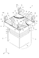
- FIG. 1 is a perspective view showing an example of the traveling vehicle system SYS according to the embodiment.
- FIG. 2 is a perspective view of a traveling vehicle V used in the traveling vehicle system SYS shown in FIG.
- FIG. 3 is a side view showing an example of the traveling vehicle V.
- FIG. 4 is a block diagram showing an example of the controller TC and the vehicle-mounted controller VC.
- the traveling vehicle system SYS is a system for transporting the article M by the traveling vehicle V in, for example, a clean room of a semiconductor manufacturing factory.
- the traveling vehicle system SYS includes a first traveling vehicle V1 to an nth traveling vehicle Vn (hereinafter, may be collectively referred to as a traveling vehicle V) (see FIG. 4) and a controller (controller TC, which controls a plurality of traveling vehicles V). In-vehicle controller VC).
- a traveling vehicle V is a ceiling traveling vehicle.
- the traveling vehicle V travels along the track R of the traveling vehicle system SYS and conveys an article M such as a FOUP accommodating a semiconductor wafer or a reticle Pod accommodating a reticle. Since the traveling vehicle V transports the article M, it may be referred to as a transport vehicle.
- the track R is laid on the ceiling or near the ceiling of a building such as a clean room.
- the track R is provided above a processing device (not shown), a stocker (automated warehouse, not shown), a buffer (not shown), or the like.
- the processing apparatus described above is, for example, an exposure apparatus, a coater developer, a film forming apparatus, an etching apparatus, and the like, and performs various processing on the semiconductor wafer in the FOUP conveyed by the traveling vehicle V.
- the stocker is provided with a stacker crane or the like (not shown), and stores an article M carried by the traveling vehicle V.
- the above buffer is a shelf installed near the load port of the processing device, and temporarily stores the article M carried by the traveling vehicle V.
- the orbit R is a grid-like orbit having a first orbit R1, a second orbit R2, and an intersection orbit R3.
- the orbital R will be referred to as a grid-like orbital R.
- the first orbit R1 extends along the X direction (first direction DR1).
- the second orbit R2 extends along the Y direction (second direction DR2).
- the first direction DR1 and the second direction DR2 are orthogonal to each other, and the plurality of first orbitals R1 and the plurality of second orbitals R2 are provided along the directions orthogonal to each other, but are in contact with each other. It is arranged so as not to.
- the crossing track R3 is arranged at the intersection of the first track R1 and the second track R2.
- the crossing track R3 is adjacent to the first track R1 in the first direction DR1 and adjacent to the second track R2 in the second direction DR2.
- the crossing track R3 forms a track of the first direction DR1 together with the first track R1, and forms a track of the second direction DR2 together with the second track R2.
- the grid-like orbit R is provided in the direction in which the first orbit R1 and the second orbit R2 are orthogonal to each other, so that a plurality of cells are adjacent to each other in a plan view and are vertically and horizontally (first direction DR1, second). They are lined up in the direction DR2).
- each cell corresponds to a grid cell C (cell).
- One grid cell C is a portion surrounded by two adjacent first orbits R1 in the second direction DR2 and two adjacent second orbits R2 in the first direction DR1 in a plan view. ..
- FIG. 1 shows a part of the grid-like orbit R, and the grid-like orbit R has the same configuration in the first direction DR1 (X direction) and the second direction DR2 (Y direction) from the configuration shown in the figure. Are continuously formed.
- the first track R1, the second track R2, and the crossing track R3 are suspended from a ceiling (not shown) by a hanging member H (see FIG. 1).
- the suspending member H includes a first portion H1 for suspending the first track R1, a second portion H2 for suspending the second track R2, and a third portion H3 for suspending the crossing track R3. , Have.
- the first portion H1 and the second portion H2 are provided at two locations sandwiching the third portion H3, respectively.
- the first track R1, the second track R2, and the crossing track R3 have traveling surfaces R1a, R2a, and R3a, respectively.
- the traveling wheels 21 of the traveling vehicle V which will be described later, roll on the traveling surfaces R1a, R2a, and R3a.
- a gap D is formed between the first track R1 and the crossing track R3, and between the second track R2 and the crossing track R3.
- the gap D is a part of the traveling vehicle V when the traveling vehicle V travels on the first track R1 and crosses the second track R2, or when traveling on the second track R2 and crosses the first track R1. This is a portion through which the connecting portion 30 described later passes. Therefore, the gap D is provided with a width through which the connecting portion 30 can pass.
- the first track R1, the second track R2, and the crossing track R3 are provided along the same or substantially the same horizontal plane.
- the first track R1, the second track R2, and the crossing track R3 are arranged on the same or substantially the same horizontal plane as the traveling surfaces R1a, R2a, and R3a.
- the traveling vehicle system SYS is equipped with a communication system CS.
- the communication system CS is used for communication between the traveling vehicle V and the controller TC.
- the traveling vehicle V and the controller TC are communicably connected via the communication system CS.
- the grid-like track R allows the traveling vehicle V to selectively travel to either the first direction DR1 or the second direction DR2.
- a blocking section in which exclusive control is performed so as not to allow another traveling vehicle V to enter when occupied by any one of the plurality of traveling vehicles V is set. That is, the grid cell C is also an area as a blocking section.
- the traveling vehicle V in the predetermined grid cell C can proceed to the grid cell C when the occupancy permission of the adjacent grid cell C is obtained from the controller TC, but the occupancy permission cannot be obtained from the controller TC. Does not proceed to the grid cell C, but stops at a predetermined grid cell C. By granting the occupancy permission in the grid cell C in this way, it is possible to prevent interference between the traveling vehicles V.
- the traveling vehicle V includes a main body portion 10, a traveling portion 20, a connecting portion 30, and an in-vehicle controller VC.
- the main body 10 is arranged below the grid-like track R (-Z side).
- the main body 10 is formed, for example, in a rectangular shape in a plan view.
- the main body 10 is formed in a size that fits in one grid cell C (see FIG. 1) in the grid-like orbit R in a plan view. Therefore, the main bodies 10 do not interfere with each other when passing by another traveling vehicle V traveling on the adjacent first track R1 or second track R2.
- the main body 10 includes an upper unit 17 and a transfer device 18.
- the upper unit 17 is suspended from the traveling portion 20 via the connecting portion 30.
- the upper unit 17 has, for example, a rectangular shape in a plan view, and has four corners on the upper surface 17a. Each of the four corner portions is connected to the traveling portion 20. By connecting the four corner portions to the traveling portion 20, the main body portion 10 can be stably suspended, and the main body portion 10 can be stably traveled.
- the transfer device 18 is provided below the upper unit 17. By using the transfer device 18, the traveling vehicle V can deliver the article M to a predetermined position.
- the transfer device 18 includes an article holding unit 13 that holds the article M, an elevating drive unit 14 that moves the article holding unit 13 up and down in the vertical direction, and a side-out mechanism 11 that slides the elevating drive unit 14 in the horizontal direction. It has a rotating portion 12 for rotating the horizontal alignment mechanism 11.
- the article holding portion 13 suspends and holds the article M by gripping the flange portion Ma of the article M.
- the article holding portion 13 is, for example, a chuck having a claw portion 13a that can move in the horizontal direction, and the claw portion 13a is advanced below the flange portion Ma of the article M to raise the article holding portion 13 to raise the article. Hold M.
- the article holding portion 13 is connected to a hanging member 13b such as a wire or a belt.
- the operation of the claw portion 13a is controlled by the vehicle-mounted controller VC.
- the elevating drive unit 14 is, for example, a hoist, and the article holding portion 13 is lowered by feeding out the hanging member 13b, and the article holding portion 13 is raised by winding up the hanging member 13b.
- the elevating drive unit 14 is controlled by the vehicle-mounted controller VC to lower or raise the article holding unit 13 at a predetermined speed. Further, the elevating drive unit 14 is controlled by the vehicle-mounted controller VC to hold the article holding unit 13 at a target height.
- the side-out mechanism 11 has, for example, a plurality of movable plates arranged so as to be stacked in the Z direction.
- the movable plate is relatively movable in the Y direction.
- An elevating drive unit 14 is attached to the lowermost movable plate.
- the side-out mechanism 11 moves the movable plate by a drive device (not shown), and makes the elevating drive unit 14 and the article holding unit 13 attached to the lowermost movable plate orthogonal to, for example, the traveling direction of the traveling vehicle V. It can be moved horizontally (sliding).
- the operation of the movable plate is controlled by the in-vehicle controller VC.
- the rotating portion 12 is provided between the side-out mechanism 11 and the upper unit 17.
- the rotating unit 12 has a rotating member 12a and a rotating driving unit 12b.
- the rotating member 12a is provided so as to be rotatable in the axial direction in the vertical direction.
- the rotating member 12a supports the side-out mechanism 11 on the lower surface side.
- an electric motor or the like is used to rotate the rotation member 12a in the axial direction of the rotation shaft AX1.
- the rotating unit 12 rotates the rotating member 12a by the driving force from the rotating driving unit 12b, and rotates the side-out mechanism 11 (elevating drive unit 14 and the article holding unit 13) in the axial direction of the rotating shaft AX1. Let me. That is, the rotating unit 12 rotates the transfer device 18 around the rotation axis AX1.
- a cover W may be provided so as to surround the transfer device 18 and the article M held by the transfer device 18.
- the cover W has a tubular shape with the lower end open, and has a shape in which a portion where the movable plate of the lateral protrusion mechanism 11 protrudes is cut out.
- the upper end of the cover W is attached to the rotating member 12a of the rotating portion 12, and the cover W rotates around the axis of the rotating shaft AX1 as the rotating member 12a rotates.
- the traveling unit 20 has a traveling wheel 21 and an auxiliary wheel 22.
- the traveling wheels 21 are arranged at the four corners of the upper surface 17a of the upper unit 17 (main body 10).
- Each of the traveling wheels 21 is attached to an axle provided on the connecting portion 30.
- the axles are provided parallel or substantially parallel along the XY plane.
- Each of the traveling wheels 21 is rotationally driven by the driving force of the traveling driving unit 33, which will be described later.
- Each of the traveling wheels 21 rolls on the traveling surfaces R1a, R2a, and R3a of the first orbit R1, the second orbit R2, and the crossing orbit R3 on the grid-like track R, and travels the traveling vehicle V. It should be noted that not all of the four traveling wheels 21 are rotationally driven by the driving force of the traveling driving unit 33, and a part of the four traveling wheels 21 may be rotationally driven.
- the traveling wheel 21 is provided so as to be able to turn in the ⁇ Z direction about the turning shaft AX2.
- One auxiliary wheel 22 is arranged before and after the traveling wheel 21 in the traveling direction.
- Each of the auxiliary wheels 22, like the traveling wheels 21, is rotatable around an axle parallel or substantially parallel along the XY plane.
- the lower end of the auxiliary wheel 22 is set to be higher than the lower end of the traveling wheel 21. Therefore, when the traveling wheel 21 is traveling on the traveling surfaces R1a, R2a, and R3a, the auxiliary wheel 22 does not come into contact with the traveling surfaces R1a, R2a, and R3a. Further, when the traveling wheel 21 passes through the gap D (see FIG.
- the auxiliary wheel 22 comes into contact with the traveling surfaces R1a, R2a, and R3a to prevent the traveling wheel 21 from falling. It should be noted that the present invention is not limited to providing two auxiliary wheels 22 on one traveling wheel 21, and for example, one auxiliary wheel 22 may be provided on one traveling wheel 21, or one auxiliary wheel 22 may not be provided. May be good.
- the connecting portion 30 connects the upper unit 17 of the main body portion 10 and the traveling portion 20.
- the connecting portion 30 is provided at each of the four corner portions of the upper surface 17a of the upper unit 17 (main body portion 10).
- the main body portion 10 is suspended from the traveling portion 20 by the connecting portion 30, and is arranged below the grid-like track R.
- the connecting portion 30 has a support member 31 and a connecting member 32.
- the support member 31 rotatably supports the rotation shaft of the traveling wheel 21 and the rotation shaft of the auxiliary wheel 22.
- the support member 31 holds the relative position between the traveling wheel 21 and the auxiliary wheel 22.
- the support member 31 is formed in a plate shape, for example, and has a thickness that allows it to pass through the gap D (see FIG. 1).
- the connecting member 32 extends downward from the support member 31 and is connected to the upper surface 17a of the upper unit 17 to hold the upper unit 17.
- the connecting member 32 is provided internally with a transmission mechanism for transmitting the driving force of the traveling drive unit 33, which will be described later, to the traveling wheels 21.
- This transmission mechanism may be configured to use a chain or a belt, or may be configured to use a gear train.
- the connecting member 32 is provided so as to be swivelable in the ⁇ Z direction about the swivel shaft AX2. By turning the connecting member 32 around the turning shaft AX2, the traveling wheel 21 can be turned in the ⁇ Z direction around the turning shaft AX2 via the support member 31.
- the connecting unit 30 includes a traveling drive unit 33 and a direction changing mechanism 34.
- the traveling drive unit 33 is attached to the connecting member 32.
- the traveling drive unit 33 is a drive source for driving the traveling wheels 21, and for example, an electric motor or the like is used.
- Each of the four traveling wheels 21 is driven by the traveling drive unit 33 to become a drive wheel.
- the four traveling wheels 21 are controlled by the vehicle-mounted controller VC so as to have the same or substantially the same rotation speed. If any one of the four traveling wheels 21 is not used as the driving wheel, the traveling drive unit 33 cannot be attached to the connecting member 32.
- the direction changing mechanism 34 turns the connecting member 32 of the connecting portion 30 around the turning shaft AX2, thereby turning the traveling wheel 21 in the ⁇ Z direction around the turning shaft AX2.
- the traveling vehicle V changes from the first state in which the traveling direction is the first direction DR1 to the second state in which the traveling direction is the second direction DR2, or the traveling direction is the second direction. It is possible to switch from the second state in which the DR2 is set to the first state in which the traveling direction is the first direction DR1.
- the direction changing mechanism 34 has a drive source 35, a pinion gear 36, and a rack 37.
- the drive source 35 is attached to a side surface of the traveling drive unit 33 away from the swivel shaft AX2.
- As the drive source 35 for example, an electric motor or the like is used.
- the pinion gear 36 is attached to the lower surface side of the drive source 35, and is rotationally driven in the ⁇ Z direction by the driving force generated by the drive source 35.
- the pinion gear 36 has a circular shape in a plan view and has a plurality of teeth in the circumferential direction of the outer circumference.
- the rack 37 is fixed to the upper surface 17a of the upper unit 17.
- the rack 37 is provided at each of the four corners of the upper surface 17a of the upper unit 17, and is provided in an arc shape (fan shape) centered on the turning shaft AX2 of the traveling wheel 21.
- the rack 37 has a plurality of teeth that mesh with the teeth of the pinion gear 36 in the circumferential direction on the outer peripheral side.
- the pinion gear 36 and the rack 37 are arranged so that their teeth are in mesh with each other.
- the pinion gear 36 rotates in the ⁇ Z direction, the pinion gear 36 moves in the circumferential direction around the swivel shaft AX2 along the outer circumference of the rack 37.
- the connecting member 32 turns, and the traveling drive unit 33 and the direction changing mechanism 34 turn together with the pinion gear 36 in the circumferential direction around the turning shaft AX2.
- each of the traveling wheel 21 and the auxiliary wheel 22 arranged at the four corners of the upper surface 17a turns around the turning shaft AX2 in the range of 90 degrees in the ⁇ Z direction.
- the drive of the direction changing mechanism 34 is controlled by the vehicle-mounted controller VC.
- the vehicle-mounted controller VC may turn the four traveling wheels 21 at the same timing or at different timings.
- the traveling wheel 21 and the auxiliary wheel 22 shifts from the state of being in contact with one of the first track R1 and the second track R2 to the state of being in contact with the other.
- the direction of the rotation axis of the traveling wheel 21 shifts from one of the first direction DR1 and the second direction DR2 to the other. Therefore, it is possible to switch between the first state in which the traveling direction of the traveling vehicle V is the first direction DR1 (X direction) and the second state in which the traveling direction is the second direction DR2 (Y direction).
- the traveling vehicle V is provided with a position detection unit (not shown) that detects the position information of the own vehicle.
- This position detection unit detects the current position of the own vehicle by detecting a position marker (not shown) indicating the position information.
- the position detection unit detects the position marker by non-contact.
- the position markers are installed for each grid cell C (each area) of the grid-like track R, for example.
- the in-vehicle controller VC comprehensively controls the traveling vehicle V.
- the in-vehicle controller VC includes a storage unit 51 that stores (stores) various data, a communication unit 52, a travel control unit 53, a transfer control unit 54, a state information processing unit 55, and the like. It includes an occupancy permission requesting unit 56.
- the in-vehicle controller VC is, for example, a computer device. Although the in-vehicle controller VC is shown in the upper unit 17 of the main body 10 in the present embodiment, it may be provided on the cover W or outside the main body 10.
- the communication unit 52 wirelessly communicates with the controller TC or another device (external device).
- the travel control unit 53 controls the travel of the traveling vehicle V by controlling the travel drive unit 33 and the direction changing mechanism 34.
- the travel control unit 53 controls, for example, travel (travel speed), operation related to stopping, and operation related to direction change.
- the travel control unit 53 controls travel based on a travel command CM described later.
- the transfer control unit 54 controls the transfer operation by controlling the transfer device 18.
- the transfer control unit 54 controls a load-grabbing operation of gripping and holding the article M arranged at a predetermined place, and an unloading operation of lowering and releasing the held article M to a predetermined place.
- the state information processing unit 55 periodically generates and updates the state information A.
- the state information A is stored in the storage unit 51.
- the state information processing unit 55 transmits the state information A to the controller TC via the communication unit 52.
- the state information A is, for example, information on the current position of the own vehicle, information indicating the current moving speed, information indicating the presence or absence of a load, and execution states of various commands such as a running command CM (execution, execution completion, execution failure). Includes information about.
- the occupancy permission requesting unit 56 When the traveling vehicle V travels on the grid-like track R according to the traveling command CM, the occupancy permission requesting unit 56 is adjacent to the grid from the current grid cell (predetermined grid cell) C in the traveling direction specified in the traveling command CM. Generate an possession permission request to proceed to cell C.
- the occupancy permission request unit 56 may generate an occupancy permission request for each grid cell C adjacent to the current grid cell C in the traveling direction, or a plurality of grid cells C in the traveling direction from the current grid cell C. Multiple occupancy permission requests may be generated for.
- the occupancy permission request generated by the occupancy permission request unit 56 is transmitted to the controller TC via the communication unit 52.
- the possession permission request may be included in the state information A and transmitted, or may be transmitted separately from the state information A.
- the controller TC controls the traveling vehicle V by transmitting various commands to the traveling vehicle V.
- the controller TC stores (stores) various data, a storage unit 61, a communication unit 62, a travel command generation unit 63, an allocation unit 64, a state information request unit 65, an occupancy permission determination unit 66, and a determination unit. It has 67 and a timer 68.
- the controller TC is, for example, a computer device including a CPU, a main memory, a storage device, a communication device, and the like, and processes various information.
- the controller TC performs, for example, processing of various information (data), storage of information, input / output of information, communication (transmission / reception) of information, and the like.
- information or a control program necessary for controlling each traveling vehicle V is stored in the storage unit 61.
- the configuration of the controller TC shown in FIG. 4 is an example, and other configurations may be applied.
- the communication unit 62 wirelessly communicates with the in-vehicle controller VC or another device (external device).
- the travel command generation unit 63 generates a travel command CM.
- the travel command CM is a command for traveling the traveling vehicle V along a predetermined route.
- the travel command CM may be a command including the travel route of the traveling vehicle V, or may be a command in which the destination is specified without including the traveling route of the traveling vehicle V.
- the vehicle-mounted controller VC of the traveling vehicle V generates a travel route to the destination specified in the travel command CM.
- the allocation unit 64 allocates the travel command CM generated by the travel command generation unit 63 to the traveling vehicle V.
- the state information requesting unit 65 transmits a state information request command RQ requesting the traveling vehicle V to transmit the state information A.
- the occupancy permission determination unit 66 receives the occupancy permission request transmitted from the vehicle-mounted controller VC, and determines whether or not to give the occupancy permission of the grid cell C, which is the object of the occupancy permission, to the traveling vehicle V that has issued the occupancy permission request. to decide. If the occupancy permission determination unit 66 has already transmitted the occupancy permission of the grid cell C to the other traveling vehicle V (when the grid cell C is occupied by any traveling vehicle V), the other traveling vehicle V Only after confirming that the vehicle V has advanced to another grid cell C (after the occupancy in the grid cell C is released), the occupancy permission is not given. When granting the occupancy permission in the grid cell C, the occupancy permission determination unit 66 generates information regarding the occupancy permission and transmits the information regarding the occupancy permission to the traveling vehicle V that has transmitted the occupancy permission request via the communication unit 62.
- the controller TC includes the occupancy permission determination unit 66, but the present invention is not limited to this embodiment.
- the occupancy permission determination unit 66 may be provided in a controller (for example, a blocking controller) different from the controller TC.
- the determination unit 67 makes various determinations based on the state information A from the traveling vehicle V. For example, the determination unit 67 determines whether or not the traveling vehicle V is continuously stopped in the predetermined grid cell C for a predetermined time. In other words, it is determined whether or not a predetermined time has elapsed while the traveling vehicle V is stopped, starting from the time when the traveling vehicle V is stopped. In this case, the determination unit 67 detects whether or not the current moving speed is zero in the state information A, and determines that the traveling vehicle V is stopped when the moving speed is zero (or almost zero).
- the determination unit 67 measures the stop time by the timer 68, and when the traveling vehicle V is no longer stopped (when the moving speed is not zero), it is measured. Is stopped, but if the stopped state continues, the measurement is continued. Then, the determination unit 67 determines whether or not the stop time measured by the timer 68 has reached a predetermined threshold value. When it is detected that the stop time has reached a predetermined threshold value, the determination unit 67 determines that the traveling vehicle V has been stopped continuously for a predetermined time.
- the traveling command generation unit 63 replaces the direction (first direction DR1) in which the traveling vehicle V is going to travel according to the previous traveling command CM. Then, from the grid cell (predetermined grid cell) C in which the traveling vehicle V is stopped, a waypoint for heading to the destination from the grid cell C of multiple destinations (multiple squares ahead) in different directions (second direction DR2). A new travel command CM is generated.
- the new travel command CM generated by the travel command generation unit 63 is assigned by the allocation unit 64 to the traveling vehicle V that has been stopped continuously for a predetermined time.
- the determination unit 67 determines whether or not the traveling vehicle V to which the new traveling command CM has been assigned has reached or approached the waypoint indicated by the traveling command CM. For example, the determination unit 67 detects the grid cell C, which is the current position of the traveling vehicle V in the state information A, and is arranged at a distance (or between) between the current grid cell C and the grid cell C at the waypoint. The number of grid cells C) is calculated. The determination unit 67 determines that the traveling vehicle V has reached the waypoint when the calculation result is 0, or when the calculation result is equal to or less than a predetermined threshold value, the traveling vehicle V approaches the waypoint. It is determined that it has been done.
- the determination unit 67 may determine whether or not there is a section that cannot proceed in the travel route of the new travel command CM.
- the travel command generation unit 63 uses the grid cell C in front of the section that cannot travel as a transit point for new travel.
- a command CM may be generated.
- the new travel command CM generated by the travel command generation unit 63 is assigned by the allocation unit 64 to the traveling vehicle V that has been stopped continuously for a predetermined time.
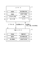
- FIG. 5 is a diagram showing an example of an operation sequence of the traveling vehicle system SYS.
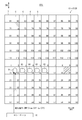
- FIG. 6 is a diagram showing an example of the operation of the traveling vehicle V in the traveling vehicle system SYS. Note that FIG. 6 and FIGS. 8 to 10 described later show a part of the grid-like orbit R. Further, in FIGS. 6 and 8 to 10, the numbers indicated by the numbers "1 to 60" or "1 to 120" indicate grid cells C1 to C60 or grid cells C1 to C120, respectively.
- the travel command generation unit 63 of the controller TC generates the travel command CM1.
- the travel command CM1 is a command for traveling along a travel path shown as a two-dot chain line from grid cell C42 to grid cell C19.
- the travel command CM1 may be a transport command for transporting the article M placed at the corresponding position of the grid cell C42 to the grid cell C19.
- the allocation unit 64 allocates the generated travel command CM1 to the traveling vehicle V (step S1).
- the allocation unit 64 selects, for example, the traveling vehicle V1 capable of transporting the article M from the plurality of traveling vehicles V, and allocates the traveling command CM1 to the selected traveling vehicle V1.
- the controller TC includes state information of each traveling vehicle V, map information indicating the position of each part (eg, processing device, storage device, buffer) related to the traveling vehicle system SYS, position information of the article M, etc. (hereinafter, these information). Is called system information). Based on this information, the allocation unit 64 allocates the travel command CM1 to the traveling vehicle V1 capable of transporting the article M.
- the controller TC updates the system information by periodically communicating with the traveling vehicles V1 to Vn.
- the traveling control unit 53 of the vehicle-mounted controller VC controls the traveling based on the traveling command CM1 and executes the traveling command CM1 (step S2).
- step S2 when the traveling vehicle V1 travels on the grid-like track R, as described above, the next grid cell C (adjacent grid cell C) in the traveling direction from the grid cell C42 (predetermined grid cell C).
- the occupancy permission request unit 56 transmits an occupancy permission request to the controller TC.
- the controller TC determines whether or not the grid cell C, which is the target of the occupancy permission request, can proceed by the occupancy permission determination unit 66 (see FIG. 4), and if it is possible to proceed, the controller TC determines whether or not the grid cell C can proceed. Send possession permission.
- the traveling vehicle V1 proceeds to the grid cell C32 after obtaining the possession permission. By sequentially repeating such an occupancy permission request and acquisition of the occupancy permission for the next grid cell C, the traveling vehicle V1 advances along the route specified in the traveling command CM1.
- the traveling vehicle V1 issues an occupancy permission request to the adjacent grid cells C one by one in the traveling direction, but the present invention is not limited to this embodiment.
- a plurality of occupancy permission requests may be collectively issued for a plurality of grid cells C32, C22, and C12 up to the grid cell C12, which is a turning point in the traveling direction of the traveling vehicle V1.
- the occupancy permission determination unit 66 of the controller TC may determine whether or not to give the occupancy permission to each of the plurality of occupancy permission requests, and collectively transmit the plurality of occupancy permits to the traveling vehicle V1.
- the controller TC transmits the state information request command RQ to the traveling vehicle V1 by the state information request unit 65 (step S3).
- the controller TC periodically requests the state information A regardless of whether or not the traveling vehicle V is executing the traveling command CM.
- the state information processing unit 55 (see FIG. 4) of the vehicle-mounted controller VC that has received the state information request command RQ transmits the state information A to the controller TC based on the state information request command RQ (step S4).
- the controller TC can grasp the current state of the traveling vehicle V1 from the state information A from the traveling vehicle V1.
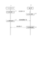
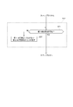
- FIG. 7 is a flowchart showing an example of a traveling vehicle control method according to the embodiment.
- FIG. 7 shows the control flow of the controller TC after the travel command CM1 is assigned to the traveling vehicle V1.
- 8 to 10 are views showing an example of the operation of the traveling vehicle system SYS.
- the traveling vehicle V1 advances from the grid cell C42 to the second direction DR2 according to the traveling command CM1 and arrives at the grid cell (area) C12, and the traveling direction is set to the first direction DR1 in the grid cell C12. Indicates the state of progress.
- step S3 of FIG. 5 described above the controller TC transmits the state information request command RQ to the traveling vehicle V1 by the state information request unit 65.
- step S4 of FIG. 5 the traveling vehicle V1 transmits the state information A to the controller TC by the state information processing unit 55. From the received state information A, the controller TC indicates that the traveling vehicle V1 is executing the execution state of the traveling command CM1, the current position is the grid cell C12, and the traveling vehicle V1 is currently stopped (at a speed of 0). There is) etc. are acquired.
- the determination unit 67 determines whether or not the traveling vehicle V1 is continuously stopped for a predetermined time (step S11).
- step S11 when the determination unit 67 recognizes that the current state of the traveling vehicle V1 is the stopped state in the state information A, the timer 68 measures the stop time of the traveling vehicle V1. When the measurement result of the timer 68 exceeds a preset threshold value, the determination unit 67 determines that the traveling vehicle V1 is continuously stopped for a predetermined time.
- the determination unit 67 repeats the determination in step S11.
- the traveling command generation unit 63 goes through the destination of the traveling vehicle V1.
- the ground grid cell C is set (step S12).
- the waypoint is, for example, a temporary destination for heading to the destination specified by the travel command CM1.
- step S12 the traveling command generation unit 63 sets the grid cells C at a plurality of destinations (plural squares ahead) in the second direction DR2 with respect to the grid cell C12 at which the traveling vehicle V1 is stopped, as a waypoint of the traveling vehicle V1.
- the travel command generation unit 63 sets a preset first predetermined number of destination grid cells C as a waypoint of the traveling vehicle V1. In this embodiment, an example in which the first predetermined number is set to 6 is shown. Therefore, as shown in FIG. 9, the travel command generation unit 63 sets the grid cell C72 six ahead (six squares ahead) from the grid cell C12 in the second direction DR2 as a stopover point of the traveling vehicle V1.
- the travel command generation unit 63 cancels the travel command CM1 while maintaining the travel command CM1 to the destination assigned to the traveling vehicle V1 under the control of itself (or the controller TC). Step S13).
- the travel command generation unit 63 or the controller TC
- the travel command CM1 or the grid cell C19 which is the destination of the travel command CM1 is stored in the storage unit 61 or the like.
- the allocation unit 64 allocates the travel command CM2 having the grid cell C72 set in step S12 as a waypoint to the traveling vehicle V1 (step S14).
- the traveling control unit 53 of the vehicle-mounted controller VC controls the traveling of the traveling vehicle V1 based on the traveling command CM2.
- the traveling vehicle V1 starts traveling in the second direction DR2 toward the grid cell C72.
- the traveling vehicle V1 When the traveling vehicle V1 is traveling, the traveling vehicle V1 repeatedly requests the occupancy permission of the next grid cell C2 in the second direction DR2, and if the occupancy permission is obtained, proceeds to the grid cell C2, and so on. Proceed to the second direction DR2 toward the cell C72. As the traveling vehicle V1 advances from the grid cell C12 to the grid cell C2, the occupied state of the grid cell C12 is eliminated. Therefore, for example, as shown in FIG. 10, another traveling vehicle V6 can advance from the grid cell C11 to the grid cell C12.
- the traveling vehicle V1 By advancing the traveling vehicle V1 from the grid cell C12 in this way, it is possible to prevent congestion of the traveling vehicle V due to the stoppage of the traveling vehicle V1. That is, when the traveling vehicle V1 becomes unable to travel, the plurality of traveling vehicles V are dispersed on the grid-like track R by advancing to a plurality of squares ahead in a direction different from the traveling direction based on the traveling command CM1. It is possible to eliminate the overcrowded state of a plurality of traveling vehicles V. Further, since the occupancy of the grid cell C12 is eliminated, another traveling vehicle V6 can proceed to the grid cell C12, and the transfer work of the article M can be executed in the grid cell C12 without delay, so that the article M can be transported. It is possible to prevent the efficiency from decreasing.
- the controller TC transmits a state information request command RQ to the traveling vehicle V1 by the state information request unit 65.
- the state information processing unit 55 of the vehicle-mounted controller VC transmits the state information A to the controller TC.
- the determination unit 67 of the controller TC determines whether or not the traveling vehicle V1 has reached or approached the grid cell C72, which is a stopover, based on the state information A from the traveling vehicle V1. (Step S15).
- step S15 the determination unit 67 detects the current position of the traveling vehicle V in the state information A, calculates the number of grid cells C up to the grid cell C72 which is the waypoint, and if the calculated number is 0, It is determined that the traveling vehicle V1 has reached the grid cell C72, or if the calculated number is less than or equal to a preset predetermined number (for example, 2), it is determined that the traveling vehicle V1 has approached the grid cell C72.
- a preset predetermined number for example, 2
- the determination unit 67 repeats the determination in step S15.
- the traveling command generation unit 63 stores from the grid cell C72 in step S13.
- the travel command CM3 up to the grid cell C19, which was the destination, is generated.
- the travel command CM3 is a command for traveling along a travel route shown as a two-dot chain line from grid cells C72 to C19, which are transit points, for example.
- the allocation unit 64 allocates the generated travel command CM3 to the traveling vehicle V (step S16).
- the traveling control unit 53 of the vehicle-mounted controller VC controls the traveling of the traveling vehicle V1 based on the traveling command CM3.
- the traveling vehicle V1 advances from the grid cell C72 to the first direction DR1 to reach the grid cell C79, and then advances in the grid cell C79 by changing the traveling direction to the second direction DR2, whereby the traveling vehicle V1 initially travels. Arrive at the destination, grid cell C19.
- the traveling vehicle V1 moves from the current grid cell C (predetermined grid cell C) to the next grid cell C (adjacent grid cell C).
- an occupancy permission request is transmitted to the controller TC, and if the occupancy permission is obtained from the controller TC, the process proceeds to the next grid cell C, but if the occupancy permission is not obtained, the operation is stopped at the current grid cell C.
- the controller TC moves from the grid cell C to the second direction DR2. Since a traveling command with the grid cell C of a plurality of destinations (multiple squares ahead) as a transit point is assigned to the traveling vehicle V, it is possible to prevent the traveling vehicle V from stopping at one grid cell C continuously for a predetermined time or longer, and the vehicle travels. It is possible to alleviate the traffic congestion of the vehicle V and suppress the occurrence of the dead lock phenomenon.
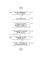
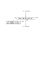
- FIG. 11 is a flowchart showing another example of the traveling vehicle control method according to the embodiment.
- 12 and 13 are diagrams showing an example of the operation of the traveling vehicle system SYS.
- the process of step S12 will be described.
- steps S11 and S13 the same processing as described above is performed.
- the determination unit 67 of the controller TC determines whether or not the waypoint can be set in step S12 (step S21).
- the travel command generation unit 63 sets the grid cell C 6 squares ahead of the grid cell C12 in the second direction DR2 as a waypoint of the traveling vehicle V1 to generate a travel command CM, which is shown in FIG.
- the grid cell C may not exist 6 squares ahead of the grid cell C12 in the second direction DR2. Further, even if the grid cell C exists 6 squares ahead, it may not be usable due to route closure due to maintenance or the like. In this way, the grid cell C as a stopover may not be specified at the preset 6 squares.
- step S21 the determination unit 67 confirms whether or not the grid cell C exists 6 squares ahead of the grid cell C12, or whether or not the grid cell C 6 squares ahead of the grid cell C12 can be used.
- the travel command generation unit 63 goes through the grid cell C. Generate a running command CM set as the ground. Further, when it is determined that the grid cell C does not exist 6 squares ahead, or the grid cell C 6 squares ahead of the grid cell C12 cannot be used, that is, when it is determined that the waypoint cannot be set (NO in step S21).
- the determination unit 67 sets the grid cell C at the second predetermined number (number of squares) less than the first predetermined number (number of squares) in the second direction DR2 from the grid cell C12 in which the traveling vehicle V1 is stopped. It is designated as a waypoint (step S22). For example, as shown in FIG. 12, in the second direction DR2, a case where the grid cell C does not exist 5 squares or later from the grid cell C12 will be described as an example.
- step S22 the determination unit 67 confirms whether or not the grid cell C exists 5 squares ahead of the grid cell C12 by using the second predetermined number (5) that is smaller than the first predetermined number (6). For example, the determination unit 67 subtracts a preset value (1 in the present embodiment) from the first predetermined number to obtain the second predetermined number, but the value subtracted from the first predetermined number can be arbitrarily set. ..
- step S22 the process returns to step S21, and it is determined whether the grid cell C exists 5 squares ahead, that is, whether the waypoint can be set. As shown in FIG. 12, since the grid cell C does not exist 5 squares ahead of the grid cell C12 in the second direction DR2, the determination unit 67 determines that the waypoint cannot be set (NO in step S21).
- step S22 is performed by NO in step S21, and 4 obtained by subtracting 1 from the first predetermined number (5: the second predetermined number) set in the previous step S22 is set as the second predetermined number. Set and specify the grid cell C 4 squares ahead. After step S22, the process returns to step S21, and it is determined whether or not the grid cell C 4 squares ahead exists. As shown in FIG. 12, since the grid cell C62 exists 4 squares ahead of the grid cell C12 in the second direction DR2, the determination unit 67 determines that the waypoint can be set (YES in step S21).
- the travel command generation unit 63 When the determination unit 67 determines that the waypoint can be set, the travel command generation unit 63 generates the travel command CM4 in which the grid cell C62 is set as the waypoint. As shown in FIG. 12, the allocation unit 64 allocates the travel command CM4 having the grid cell C62 set in step S22 as a waypoint to the traveling vehicle V1 (step S14). The traveling vehicle V1 advances to the grid cell C62 according to the traveling command CM4.
- the traveling command generation unit 63 has managed the purpose of the traveling command CM1 from the grid cell C62.
- the travel command CM5 up to the grid cell C19, which is the ground, is generated.
- the travel command CM5 is a command for traveling along a travel path indicated by a two-dot chain line from grid cells C62 to C19, for example.
- the allocation unit 64 allocates the generated travel command CM5 to the traveling vehicle V1 (step S16).
- the traveling vehicle V1 travels by traveling from the grid cell C62 to the first direction DR1 and reaching the grid cell C69 in accordance with the traveling command CM5, and then traveling in the grid cell C69 by changing the traveling direction to the second direction DR2. Arrive at grid cell C19, the original destination of car V1. In addition, even when the traveling vehicle V1 advances from the grid cell C92 to C19, as described above, the traveling vehicle V1 moves from the current grid cell C (predetermined grid cell C) to the next grid cell C (adjacent grid cell C).
- an occupancy permission request is transmitted to the controller TC, and if the occupancy permission is obtained from the controller TC, the process proceeds to the next grid cell C, but if the occupancy permission is not obtained, the operation is stopped at the current grid cell C.
- the traveling vehicle V when the traveling vehicle V is moved from the first direction DR1 to the second direction DR2, the number of grid cells C in the second direction DR2 is small. Also, since the travel command CM4 for which the waypoint is set is assigned to the traveling vehicle V, the stopped traveling vehicle V can be reliably advanced from the stopped grid cell C.
- FIG. 13 is a flowchart showing another example of the control method of the traveling vehicle according to the embodiment.
- 14 and 15 are diagrams showing an example of the operation of the traveling vehicle system SYS.
- the same processing as described above is performed for steps S11 and S12.
- the determination unit 67 of the controller TC determines whether or not the traveling vehicle V1 can travel to the grid cell C72 set as the waypoint in step S12 (step S31).
- step S31 the determination unit 67 determines whether or not each grid cell C (C2, C112, C102, C92, C82, C72) on the travel path set by the travel command CM is not occupied by another traveling vehicle V. Or, it is confirmed whether or not the occupancy permission has already been given to the other traveling vehicle V for each grid cell C on the traveling route.
- the determination unit 67 determines that the grid cell C on the traveling route is not occupied by the other traveling vehicle V or does not give the other traveling vehicle V the occupancy permission
- the determination unit 67 determines that the grid cell C72 is a stopover. It is determined that the traveling vehicle V1 can travel up to. Further, when any of the grid cells C on the traveling route is occupied by another traveling vehicle V, or when the other traveling vehicle V is given the occupancy permission, the traveling vehicle reaches the grid cell C72 which is a stopover. It is determined that V1 cannot proceed.
- the controller TC performs the processes after step S13 in the same manner as in the above embodiment.
- the traveling vehicle V1 advances to the grid cell C72.
- the point (see FIG. 10) that the traveling vehicle V1 that has traveled to the grid cell C72 advances to the grid cell C79 in the first direction DR1 and then to the destination grid cell C19 in the second direction DR2 is the same as above. is there.
- the traveling command generation unit 63 of the controller TC determines the grid cell C12 in which the traveling vehicle V1 is stopped.
- a travel command is generated with the grid cell C, which is a second predetermined number less than the first predetermined number, as a waypoint (step S32).
- the waypoint of the traveling vehicle V1 is the grid cell C72 and the traveling vehicle V7 and V8 are stopped at the grid cells C72 and C82 will be described as an example.
- step S32 the determination unit 67 uses the second predetermined number (5), which is smaller than the first predetermined number (6), and sets the grid cell C82 five squares ahead as the waypoint. For example, the determination unit 67 subtracts a preset value (1 in the present embodiment) from the first predetermined number to obtain the second predetermined number, but the value subtracted from the first predetermined number can be arbitrarily set. ..
- step S32 the process returns to step S31, and it is determined whether or not the traveling vehicle V1 can proceed to the grid cell C82 at the waypoint. As shown in FIG. 14, since the traveling vehicle V8 is stopped in the grid cell C82, the determination unit 67 determines that the traveling vehicle V1 cannot proceed to the grid cell C82 (NO in step S31).
- step S32 is performed by NO in step S31, and 4 obtained by subtracting 1 from the first predetermined number (5: the second predetermined number) set in the previous step S32 is set as the second predetermined number.
- the process returns to step S31, and it is determined whether or not the traveling vehicle V1 can proceed to the grid cell C92 at the waypoint.
- the determination unit 67 determines that the traveling vehicle V1 can proceed to the grid cell C92 (YES in step S31). ..
- the travel command generation unit 63 maintains the travel command CM1 to the destination assigned to the traveling vehicle V1 under the control of itself (or the controller TC), and the travel command CM1 Is canceled (step S13). Further, as shown in FIG. 14, the allocation unit 64 allocates the travel command CM6 set in step S32 with the grid cell C92 as a waypoint to the traveling vehicle V1 (step S14). The traveling vehicle V1 advances to the grid cell C92 according to the traveling command CM6.
- the traveling command generation unit 63 has managed the purpose of the traveling command CM1 from the grid cell C92.
- the travel command CM7 up to the grid cell C19, which is the ground, is generated.
- the travel command CM7 is a command for traveling along a travel path indicated by a two-dot chain line from grid cells C92 to C19, for example.
- the allocation unit 64 allocates the generated travel command CM7 to the traveling vehicle V1 (step S16).
- the traveling vehicle V1 travels by traveling from the grid cell C92 to the first direction DR1 and reaching the grid cell C99 in accordance with the traveling command CM7, and then traveling in the grid cell C99 by changing the traveling direction to the second direction DR2. Arrive at grid cell C19, the original destination of car V1. In addition, even when the traveling vehicle V1 advances from the grid cell C92 to C19, as described above, the traveling vehicle V1 moves from the current grid cell C (predetermined grid cell C) to the next grid cell C (adjacent grid cell C).
- an occupancy permission request is transmitted to the controller TC, and if the occupancy permission is obtained from the controller TC, the process proceeds to the next grid cell C, but if the occupancy permission is not obtained, the operation is stopped at the current grid cell C.
- the traveling vehicle V when the traveling vehicle V is changed from the first direction DR1 to the second direction DR2 and traveled, the traveling vehicle reaches the grid cell C which is the first predetermined number ahead of the waypoint.
- a traveling command with the grid cell C, which is a second predetermined number less than the first predetermined number, as a waypoint is assigned to the traveling vehicle V, so that the stopped traveling vehicle V is surely stopped. It can be advanced from grid cell C.
- the direction in which the traveling vehicle V travels is an example of the direction toward the upper side of the drawing in the second direction DR2.
- the present invention is not limited to this form.
- it may be the direction toward the lower side of the drawing in the second direction DR2.
- a ... Status information C (C1 to C120) ... Grid cell (cell) V, V1 to V8 ... Traveling vehicle M ... Article R ... Lattice track (track) R1 ... 1st track R2 ... 2nd track W ... Cover CM, CM1 to CM7 ... Travel command DR1 ... 1st direction DR2 ... 2nd direction TC ...
- Controller VC ... ⁇ ⁇ In-vehicle controller SYS ⁇ ⁇ ⁇ Traveling vehicle system 10 ⁇ ⁇ ⁇ Main body 20 ⁇ ⁇ ⁇ Traveling unit 51, 61 ⁇ ⁇ ⁇ Storage unit 52, 62 ⁇ ⁇ ⁇ Communication unit 53 ⁇ ⁇ ⁇ Travel control unit 54 ⁇ ⁇ ⁇ Transfer control unit 55 ... State information processing unit 56 ... Occupancy permission request unit 63 ... Travel command generation unit 64 ... Allocation unit 65 ... State information request unit 66 ... Occupancy permission determination unit 67 ... Judgment unit 68 ... Timer
Landscapes
- Engineering & Computer Science (AREA)
- Physics & Mathematics (AREA)
- General Physics & Mathematics (AREA)
- Radar, Positioning & Navigation (AREA)
- Remote Sensing (AREA)
- Aviation & Aerospace Engineering (AREA)
- Automation & Control Theory (AREA)
- Business, Economics & Management (AREA)
- Economics (AREA)
- Mechanical Engineering (AREA)
- Quality & Reliability (AREA)
- Entrepreneurship & Innovation (AREA)
- Human Resources & Organizations (AREA)
- Marketing (AREA)
- Operations Research (AREA)
- Development Economics (AREA)
- Strategic Management (AREA)
- Tourism & Hospitality (AREA)
- General Business, Economics & Management (AREA)
- Theoretical Computer Science (AREA)
- Control Of Position, Course, Altitude, Or Attitude Of Moving Bodies (AREA)
- Train Traffic Observation, Control, And Security (AREA)
Abstract
Description
C(C1~C120)・・・グリッドセル(セル)
V、V1~V8・・・走行車
M・・・物品
R・・・格子状軌道(軌道)
R1・・・第1軌道
R2・・・第2軌道
W・・・カバー
CM、CM1~CM7・・・走行指令
DR1・・・第1方向
DR2・・・第2方向
TC・・・コントローラ
VC・・・車載コントローラ
SYS・・・走行車システム
10・・・本体部
20・・・走行部
51、61・・・記憶部
52、62・・・通信部
53・・・走行制御部
54・・・移載制御部
55・・・状態情報処理部
56・・・占有許可要求部
63・・・走行指令生成部
64・・・割り付け部
65・・・状態情報要求部
66・・・占有許可判断部
67・・・判定部
68・・・タイマ
Claims (5)
- 複数の走行車と、
第1方向に延在する複数の第1軌道と、前記第1方向と交差する第2方向に延在する複数の第2軌道とが格子状に設けられ、前記走行車が前記第1方向及び前記第2方向のいずれかへ選択的に進行可能な軌道と、
前記複数の走行車と相互に通信可能であり、前記複数の走行車を制御するコントローラと、を備え、
前記コントローラは、
平面視において相互に隣り合う2本の前記第1軌道及び相互に隣り合う2本の前記第2軌道によって画定されるセル毎に、当該セルについて所定の走行車に占有許可を出した占有状態及びいずれの走行車にも占有許可を出さない非占有状態のいずれかを設定可能であり、
所定の前記セルから目的地に向けて前記第1方向へ進行しようとする前記走行車が存在する場合、前記所定のセルに対し前記第1方向に隣接する前記セルの占有許可を当該走行車に与えるか否かを判断し、
前記走行車は、
前記コントローラから前記隣接するセルの占有許可を得た場合に前記第1方向へ進行する一方、占有許可を得られない場合に前記所定のセルにおいて停止し、
前記コントローラは、前記走行車が前記隣接するセルの占有許可が得られず前記所定のセルにおいて所定時間継続して停止していた場合、前記所定のセルから前記第2方向における複数先の前記セルを前記目的地に向かうための経由地とする走行指令を前記走行車に割り付ける、走行車システム。 - 前記走行車が前記隣接するセルの占有許可が得られず前記所定のセルにおいて所定時間継続して停止していた場合において、前記所定のセルから前記第2方向における第1所定数先の前記セルを前記経由地として設定できない場合、又は、前記所定のセルから前記第2方向における前記経由地である第1所定数先の前記セルまで前記走行車が進行できない場合、前記コントローラは、前記所定のセルから前記第2方向における、前記第1所定数よりも少ない第2所定数先のエリアを前記経由地とする走行指令を前記走行車に割り付ける、請求項1に記載の走行車システム。
- 前記走行車が前記隣接するセルの占有許可が得られず前記所定のセルにおいて所定時間継続して停止していた場合において、前記コントローラは、前記走行車に割り付けられていた前記目的地までの走行指令を自己の管理下に維持しつつ当該走行指令を取り消す、請求項1又は請求項2に記載の走行車システム。
- 前記コントローラは、前記走行車が前記経由地に到達又は接近した場合、前記走行車に対して当該経由地から、取り消した前記走行指令における前記目的地までの走行指令を割り付ける、請求項3に記載の走行車システム。
- 複数の走行車と、
第1方向に延在する複数の第1軌道と、前記第1方向と交差する第2方向に延在する複数の第2軌道とが格子状に設けられ、前記走行車が前記第1方向及び前記第2方向のいずれかへ選択的に進行可能な軌道と、を備える走行車システムにおける、前記走行車を制御する方法であって、
平面視において相互に隣り合う2本の前記第1軌道及び相互に隣り合う2本の前記第2軌道によって画定されるセル毎に、当該セルについて所定の走行車に占有許可を出した占有状態及びいずれの走行車にも占有許可を出さない非占有状態のいずれかを設定することと、
所定の前記セルから目的地に向けて前記第1方向へ進行しようとする前記走行車が存在する場合、前記所定のセルに対し前記第1方向に隣接する前記セルの占有許可を当該走行車に与えるか否かを判断することと、
前記走行車に前記隣接するセルの占有許可を与えた場合、当該走行車を前記第1方向へ進行させ、前記走行車に前記隣接するセルの占有許可を与えない場合、当該走行車を前記所定のセルにおいて停止させることと、
前記走行車が前記隣接するセルの占有許可が得られず前記所定のセルにおいて所定時間継続して停止していた場合、前記所定のセルから前記第2方向における複数先の前記セルを前記目的地に向かうための経由地とする走行指令を前記走行車に割り付けることと、を含む、走行車の制御方法。
Priority Applications (6)
| Application Number | Priority Date | Filing Date | Title |
|---|---|---|---|
| KR1020227000799A KR102741053B1 (ko) | 2019-07-12 | 2020-05-29 | 주행차 시스템 및 주행차의 제어 방법 |
| CN202080049869.9A CN114080364B (zh) | 2019-07-12 | 2020-05-29 | 行驶车系统、以及行驶车的控制方法 |
| EP20841638.8A EP3985468B1 (en) | 2019-07-12 | 2020-05-29 | Travel vehicle system and travel vehicle control method |
| JP2021532712A JP7205629B2 (ja) | 2019-07-12 | 2020-05-29 | 走行車システム、及び走行車の制御方法 |
| US17/626,157 US11635770B2 (en) | 2019-07-12 | 2020-05-29 | Traveling vehicle system and traveling vehicle control method |
| IL289694A IL289694B2 (en) | 2019-07-12 | 2020-05-29 | Traveling vehicle system and traveling vehicle control method |
Applications Claiming Priority (2)
| Application Number | Priority Date | Filing Date | Title |
|---|---|---|---|
| JP2019-130470 | 2019-07-12 | ||
| JP2019130470 | 2019-07-12 |
Publications (1)
| Publication Number | Publication Date |
|---|---|
| WO2021010035A1 true WO2021010035A1 (ja) | 2021-01-21 |
Family
ID=74210476
Family Applications (1)
| Application Number | Title | Priority Date | Filing Date |
|---|---|---|---|
| PCT/JP2020/021297 Ceased WO2021010035A1 (ja) | 2019-07-12 | 2020-05-29 | 走行車システム、及び走行車の制御方法 |
Country Status (8)
| Country | Link |
|---|---|
| US (1) | US11635770B2 (ja) |
| EP (1) | EP3985468B1 (ja) |
| JP (1) | JP7205629B2 (ja) |
| KR (1) | KR102741053B1 (ja) |
| CN (1) | CN114080364B (ja) |
| IL (1) | IL289694B2 (ja) |
| TW (1) | TWI860381B (ja) |
| WO (1) | WO2021010035A1 (ja) |
Cited By (2)
| Publication number | Priority date | Publication date | Assignee | Title |
|---|---|---|---|---|
| US20230136087A1 (en) * | 2020-03-31 | 2023-05-04 | Autostore Technology AS | Section based speed reduction |
| JPWO2023199740A1 (ja) * | 2022-04-15 | 2023-10-19 |
Families Citing this family (6)
| Publication number | Priority date | Publication date | Assignee | Title |
|---|---|---|---|---|
| EP3862839B1 (en) * | 2020-02-10 | 2023-05-24 | Ricoh Company, Ltd. | Transport system and transport method |
| TW202327964A (zh) * | 2021-11-05 | 2023-07-16 | 日商大福股份有限公司 | 物品搬送設備 |
| CN116543544A (zh) * | 2023-04-26 | 2023-08-04 | 深圳一清创新科技有限公司 | 车辆调度方法、自动驾驶车辆以及电子设备 |
| JP7831428B2 (ja) * | 2023-07-19 | 2026-03-17 | 株式会社ダイフク | 物品搬送設備 |
| WO2025142281A1 (ja) * | 2023-12-28 | 2025-07-03 | 日本電気株式会社 | 移動体制御システム、移動体制御方法、移動体制御装置、及び、制御プログラム |
| CN120057518B (zh) * | 2025-04-29 | 2025-08-05 | 苏州新施诺半导体设备有限公司 | 行驶车系统 |
Citations (5)
| Publication number | Priority date | Publication date | Assignee | Title |
|---|---|---|---|---|
| JPH07219633A (ja) * | 1993-12-10 | 1995-08-18 | Shinko Electric Co Ltd | 運行管理制御装置およびその方法 |
| JP2006313461A (ja) | 2005-05-09 | 2006-11-16 | Murata Mach Ltd | 搬送台車システム |
| JP2017134794A (ja) * | 2016-01-29 | 2017-08-03 | パナソニックIpマネジメント株式会社 | 移動ロボット制御システム及び移動ロボットを制御するサーバ装置 |
| WO2019087618A1 (ja) * | 2017-10-31 | 2019-05-09 | 村田機械株式会社 | 搬送システム |
| JP2019130470A (ja) | 2018-01-31 | 2019-08-08 | パナソニックIpマネジメント株式会社 | 水噴霧遠心集塵装置 |
Family Cites Families (16)
| Publication number | Priority date | Publication date | Assignee | Title |
|---|---|---|---|---|
| EP0213938B1 (en) * | 1985-08-30 | 1992-08-05 | Texas Instruments Incorporated | Failsafe brake for a multi-wheel vehicle with motor controlled steering |
| EP0618523B1 (en) | 1993-04-02 | 1998-12-09 | Shinko Electric Co. Ltd. | Transport management control apparatus and method for unmanned vehicle system |
| JP4933055B2 (ja) * | 2005-05-06 | 2012-05-16 | 国立大学法人 熊本大学 | ワーク搬送システム、経路設定方法及び経路設定プログラム |
| US7920962B2 (en) | 2006-06-19 | 2011-04-05 | Kiva Systems, Inc. | System and method for coordinating movement of mobile drive units |
| KR102041093B1 (ko) * | 2011-04-11 | 2019-11-06 | 크라운 이큅먼트 코포레이션 | 조정된 경로 계획기를 사용하는 다수의 자동화 비-홀로노믹 차량들을 효율적으로 스케줄링하는 방법 및 장치 |
| US9285806B2 (en) * | 2012-01-17 | 2016-03-15 | Murata Machinery, Ltd. | Traveling vehicle system |
| CN102830702B (zh) * | 2012-09-07 | 2014-10-22 | 无锡普智联科高新技术有限公司 | 一种用于密集存储区域的移动机器人路径规划方法 |
| GB201409883D0 (en) * | 2014-06-03 | 2014-07-16 | Ocado Ltd | Methods, systems, and apparatus for controlling movement of transporting devices |
| JP6507897B2 (ja) * | 2015-07-10 | 2019-05-08 | 株式会社ダイフク | 物品搬送設備 |
| US10956855B1 (en) * | 2015-08-16 | 2021-03-23 | Palidian Incorporated | Integrated multi-location scheduling, routing, and task management |
| US20170169366A1 (en) * | 2015-12-14 | 2017-06-15 | Google Inc. | Systems and Methods for Adjusting Ride-Sharing Schedules and Routes |
| JP7054379B2 (ja) * | 2016-03-03 | 2022-04-13 | 村田機械株式会社 | 搬送システム |
| WO2018068024A1 (en) * | 2016-10-06 | 2018-04-12 | Doerfer Corporation | Automated warehouse fulfillment operations and system |
| CN106647734B (zh) * | 2016-10-12 | 2020-11-24 | 北京京东乾石科技有限公司 | 自动导引车、路径规划方法与装置 |
| CN108268039A (zh) * | 2018-01-19 | 2018-07-10 | 广东美的智能机器人有限公司 | 移动机器人的路径规划方法及系统 |
| CN109501815B (zh) * | 2018-12-29 | 2024-02-27 | 广州汇宏科技有限公司 | 一种无人驾驶轻型轨道车交通系统 |
-
2020
- 2020-05-29 IL IL289694A patent/IL289694B2/en unknown
- 2020-05-29 JP JP2021532712A patent/JP7205629B2/ja active Active
- 2020-05-29 WO PCT/JP2020/021297 patent/WO2021010035A1/ja not_active Ceased
- 2020-05-29 KR KR1020227000799A patent/KR102741053B1/ko active Active
- 2020-05-29 EP EP20841638.8A patent/EP3985468B1/en active Active
- 2020-05-29 US US17/626,157 patent/US11635770B2/en active Active
- 2020-05-29 CN CN202080049869.9A patent/CN114080364B/zh active Active
- 2020-07-06 TW TW109122704A patent/TWI860381B/zh active
Patent Citations (5)
| Publication number | Priority date | Publication date | Assignee | Title |
|---|---|---|---|---|
| JPH07219633A (ja) * | 1993-12-10 | 1995-08-18 | Shinko Electric Co Ltd | 運行管理制御装置およびその方法 |
| JP2006313461A (ja) | 2005-05-09 | 2006-11-16 | Murata Mach Ltd | 搬送台車システム |
| JP2017134794A (ja) * | 2016-01-29 | 2017-08-03 | パナソニックIpマネジメント株式会社 | 移動ロボット制御システム及び移動ロボットを制御するサーバ装置 |
| WO2019087618A1 (ja) * | 2017-10-31 | 2019-05-09 | 村田機械株式会社 | 搬送システム |
| JP2019130470A (ja) | 2018-01-31 | 2019-08-08 | パナソニックIpマネジメント株式会社 | 水噴霧遠心集塵装置 |
Cited By (2)
| Publication number | Priority date | Publication date | Assignee | Title |
|---|---|---|---|---|
| US20230136087A1 (en) * | 2020-03-31 | 2023-05-04 | Autostore Technology AS | Section based speed reduction |
| JPWO2023199740A1 (ja) * | 2022-04-15 | 2023-10-19 |
Also Published As
| Publication number | Publication date |
|---|---|
| TWI860381B (zh) | 2024-11-01 |
| US11635770B2 (en) | 2023-04-25 |
| US20220244742A1 (en) | 2022-08-04 |
| KR102741053B1 (ko) | 2024-12-10 |
| TW202109225A (zh) | 2021-03-01 |
| EP3985468A1 (en) | 2022-04-20 |
| CN114080364A (zh) | 2022-02-22 |
| KR20220020354A (ko) | 2022-02-18 |
| EP3985468A4 (en) | 2023-06-28 |
| JP7205629B2 (ja) | 2023-01-17 |
| IL289694B2 (en) | 2023-12-01 |
| CN114080364B (zh) | 2023-09-19 |
| IL289694B1 (en) | 2023-08-01 |
| JPWO2021010035A1 (ja) | 2021-01-21 |
| EP3985468B1 (en) | 2025-12-24 |
| IL289694A (en) | 2022-03-01 |
Similar Documents
| Publication | Publication Date | Title |
|---|---|---|
| WO2021010035A1 (ja) | 走行車システム、及び走行車の制御方法 | |
| JP6652106B2 (ja) | 物品搬送設備 | |
| CN114341026B (zh) | 搬运系统及网格系统 | |
| JP7226537B2 (ja) | 走行車システム及び走行車の制御方法 | |
| JP6863329B2 (ja) | 走行車システム及び走行車の制御方法 | |
| JP7435605B2 (ja) | 搬送車 | |
| JP4766111B2 (ja) | 搬送車システム | |
| WO2021220582A1 (ja) | 天井搬送車及び天井搬送システム | |
| JP7235106B2 (ja) | 走行車システム及び走行車の制御方法 | |
| TWI772620B (zh) | 物品搬送設備 | |
| CN119948613A (zh) | 旋转机构及高架搬送车 |
Legal Events
| Date | Code | Title | Description |
|---|---|---|---|
| 121 | Ep: the epo has been informed by wipo that ep was designated in this application |
Ref document number: 20841638 Country of ref document: EP Kind code of ref document: A1 |
|
| ENP | Entry into the national phase |
Ref document number: 20227000799 Country of ref document: KR Kind code of ref document: A |
|
| ENP | Entry into the national phase |
Ref document number: 2021532712 Country of ref document: JP Kind code of ref document: A |
|
| NENP | Non-entry into the national phase |
Ref country code: DE |
|
| ENP | Entry into the national phase |
Ref document number: 2020841638 Country of ref document: EP Effective date: 20220111 |
|
| WWG | Wipo information: grant in national office |
Ref document number: 2020841638 Country of ref document: EP |