WO2021010419A1 - 回転伝達装置および車両用操舵装置 - Google Patents
回転伝達装置および車両用操舵装置 Download PDFInfo
- Publication number
- WO2021010419A1 WO2021010419A1 PCT/JP2020/027498 JP2020027498W WO2021010419A1 WO 2021010419 A1 WO2021010419 A1 WO 2021010419A1 JP 2020027498 W JP2020027498 W JP 2020027498W WO 2021010419 A1 WO2021010419 A1 WO 2021010419A1
- Authority
- WO
- WIPO (PCT)
- Prior art keywords
- transmission device
- rotation transmission
- input shaft
- tubular portion
- case
- Prior art date
- Legal status (The legal status is an assumption and is not a legal conclusion. Google has not performed a legal analysis and makes no representation as to the accuracy of the status listed.)
- Ceased
Links
Images




Classifications
-
- F—MECHANICAL ENGINEERING; LIGHTING; HEATING; WEAPONS; BLASTING
- F16—ENGINEERING ELEMENTS AND UNITS; GENERAL MEASURES FOR PRODUCING AND MAINTAINING EFFECTIVE FUNCTIONING OF MACHINES OR INSTALLATIONS; THERMAL INSULATION IN GENERAL
- F16J—PISTONS; CYLINDERS; SEALINGS
- F16J15/00—Sealings
- F16J15/16—Sealings between relatively-moving surfaces
- F16J15/32—Sealings between relatively-moving surfaces with elastic sealings, e.g. O-rings
- F16J15/3204—Sealings between relatively-moving surfaces with elastic sealings, e.g. O-rings with at least one lip
-
- F—MECHANICAL ENGINEERING; LIGHTING; HEATING; WEAPONS; BLASTING
- F16—ENGINEERING ELEMENTS AND UNITS; GENERAL MEASURES FOR PRODUCING AND MAINTAINING EFFECTIVE FUNCTIONING OF MACHINES OR INSTALLATIONS; THERMAL INSULATION IN GENERAL
- F16D—COUPLINGS FOR TRANSMITTING ROTATION; CLUTCHES; BRAKES
- F16D41/00—Freewheels or freewheel clutches
- F16D41/06—Freewheels or freewheel clutches with intermediate wedging coupling members between an inner and an outer surface
- F16D41/08—Freewheels or freewheel clutches with intermediate wedging coupling members between an inner and an outer surface with provision for altering the freewheeling action
- F16D41/086—Freewheels or freewheel clutches with intermediate wedging coupling members between an inner and an outer surface with provision for altering the freewheeling action the intermediate members being of circular cross-section and wedging by rolling
- F16D41/088—Freewheels or freewheel clutches with intermediate wedging coupling members between an inner and an outer surface with provision for altering the freewheeling action the intermediate members being of circular cross-section and wedging by rolling the intermediate members being of only one size and wedging by a movement not having an axial component, between inner and outer races, one of which is cylindrical
-
- B—PERFORMING OPERATIONS; TRANSPORTING
- B62—LAND VEHICLES FOR TRAVELLING OTHERWISE THAN ON RAILS
- B62D—MOTOR VEHICLES; TRAILERS
- B62D1/00—Steering controls, i.e. means for initiating a change of direction of the vehicle
- B62D1/02—Steering controls, i.e. means for initiating a change of direction of the vehicle vehicle-mounted
- B62D1/16—Steering columns
- B62D1/20—Connecting steering column to steering gear
-
- B—PERFORMING OPERATIONS; TRANSPORTING
- B62—LAND VEHICLES FOR TRAVELLING OTHERWISE THAN ON RAILS
- B62D—MOTOR VEHICLES; TRAILERS
- B62D5/00—Power-assisted or power-driven steering
- B62D5/001—Mechanical components or aspects of steer-by-wire systems, not otherwise provided for in this maingroup
- B62D5/003—Backup systems, e.g. for manual steering
-
- F—MECHANICAL ENGINEERING; LIGHTING; HEATING; WEAPONS; BLASTING
- F16—ENGINEERING ELEMENTS AND UNITS; GENERAL MEASURES FOR PRODUCING AND MAINTAINING EFFECTIVE FUNCTIONING OF MACHINES OR INSTALLATIONS; THERMAL INSULATION IN GENERAL
- F16C—SHAFTS; FLEXIBLE SHAFTS; ELEMENTS OR CRANKSHAFT MECHANISMS; ROTARY BODIES OTHER THAN GEARING ELEMENTS; BEARINGS
- F16C19/00—Bearings with rolling contact, for exclusively rotary movement
- F16C19/54—Systems consisting of a plurality of bearings with rolling friction
-
- F—MECHANICAL ENGINEERING; LIGHTING; HEATING; WEAPONS; BLASTING
- F16—ENGINEERING ELEMENTS AND UNITS; GENERAL MEASURES FOR PRODUCING AND MAINTAINING EFFECTIVE FUNCTIONING OF MACHINES OR INSTALLATIONS; THERMAL INSULATION IN GENERAL
- F16D—COUPLINGS FOR TRANSMITTING ROTATION; CLUTCHES; BRAKES
- F16D27/00—Magnetically- or electrically- actuated clutches; Control or electric circuits therefor
- F16D27/10—Magnetically- or electrically- actuated clutches; Control or electric circuits therefor with an electromagnet not rotating with a clutching member, i.e. without collecting rings
- F16D27/108—Magnetically- or electrically- actuated clutches; Control or electric circuits therefor with an electromagnet not rotating with a clutching member, i.e. without collecting rings with axially movable clutching members
-
- F—MECHANICAL ENGINEERING; LIGHTING; HEATING; WEAPONS; BLASTING
- F16—ENGINEERING ELEMENTS AND UNITS; GENERAL MEASURES FOR PRODUCING AND MAINTAINING EFFECTIVE FUNCTIONING OF MACHINES OR INSTALLATIONS; THERMAL INSULATION IN GENERAL
- F16J—PISTONS; CYLINDERS; SEALINGS
- F16J15/00—Sealings
- F16J15/16—Sealings between relatively-moving surfaces
- F16J15/32—Sealings between relatively-moving surfaces with elastic sealings, e.g. O-rings
- F16J15/3204—Sealings between relatively-moving surfaces with elastic sealings, e.g. O-rings with at least one lip
- F16J15/3232—Sealings between relatively-moving surfaces with elastic sealings, e.g. O-rings with at least one lip having two or more lips
-
- F—MECHANICAL ENGINEERING; LIGHTING; HEATING; WEAPONS; BLASTING
- F16—ENGINEERING ELEMENTS AND UNITS; GENERAL MEASURES FOR PRODUCING AND MAINTAINING EFFECTIVE FUNCTIONING OF MACHINES OR INSTALLATIONS; THERMAL INSULATION IN GENERAL
- F16C—SHAFTS; FLEXIBLE SHAFTS; ELEMENTS OR CRANKSHAFT MECHANISMS; ROTARY BODIES OTHER THAN GEARING ELEMENTS; BEARINGS
- F16C2326/00—Articles relating to transporting
- F16C2326/20—Land vehicles
- F16C2326/24—Steering systems, e.g. steering rods or columns
-
- F—MECHANICAL ENGINEERING; LIGHTING; HEATING; WEAPONS; BLASTING
- F16—ENGINEERING ELEMENTS AND UNITS; GENERAL MEASURES FOR PRODUCING AND MAINTAINING EFFECTIVE FUNCTIONING OF MACHINES OR INSTALLATIONS; THERMAL INSULATION IN GENERAL
- F16D—COUPLINGS FOR TRANSMITTING ROTATION; CLUTCHES; BRAKES
- F16D23/00—Details of mechanically-actuated clutches not specific for one distinct type
- F16D23/12—Mechanical clutch-actuating mechanisms arranged outside the clutch as such
- F16D2023/123—Clutch actuation by cams, ramps or ball-screw mechanisms
-
- F—MECHANICAL ENGINEERING; LIGHTING; HEATING; WEAPONS; BLASTING
- F16—ENGINEERING ELEMENTS AND UNITS; GENERAL MEASURES FOR PRODUCING AND MAINTAINING EFFECTIVE FUNCTIONING OF MACHINES OR INSTALLATIONS; THERMAL INSULATION IN GENERAL
- F16D—COUPLINGS FOR TRANSMITTING ROTATION; CLUTCHES; BRAKES
- F16D41/00—Freewheels or freewheel clutches
- F16D41/06—Freewheels or freewheel clutches with intermediate wedging coupling members between an inner and an outer surface
- F16D41/064—Freewheels or freewheel clutches with intermediate wedging coupling members between an inner and an outer surface the intermediate members wedging by rolling and having a circular cross-section, e.g. balls
- F16D41/066—Freewheels or freewheel clutches with intermediate wedging coupling members between an inner and an outer surface the intermediate members wedging by rolling and having a circular cross-section, e.g. balls all members having the same size and only one of the two surfaces being cylindrical
- F16D41/067—Freewheels or freewheel clutches with intermediate wedging coupling members between an inner and an outer surface the intermediate members wedging by rolling and having a circular cross-section, e.g. balls all members having the same size and only one of the two surfaces being cylindrical and the members being distributed by a separate cage encircling the axis of rotation
Definitions
- the present invention relates to a rotation transmission device used for switching between rotation transmission and interruption, and a vehicle steering device using the rotation transmission device.
- Patent Document 1 As a rotation transmission device used for switching between a state in which rotation is transmitted from an input shaft to an output shaft and a state in which rotation is cut off, for example, the one described in Patent Document 1 is known.
- the rotation transmission device described in Patent Document 1 has a cylindrical case with both ends open, an input shaft arranged in a state where one end is housed in the case, and an input shaft in a state where one end is housed in the case.
- the output shafts arranged in a straight line, the inner ring provided in the housing portion of the input shaft in the case, and the storage portion of the output shaft in the case are connected so as to rotate integrally with the output shaft. It has an outer ring provided, a pair of rollers incorporated between a cylindrical surface on the inner circumference of the outer ring and a cam surface on the outer circumference of the inner ring, and a roller cage for holding the pair of rollers.
- the roller cage consists of two split cages that are supported so that they can rotate relative to each other.
- the two split cages are in charge of engaging positions for engaging the pair of rollers between the cylindrical surface on the inner circumference of the outer ring and the cam surface on the outer circumference of the inner ring, and disengaging each roller. It is possible to move to and from the release position.
- the case of the rotation transmission device includes a cylindrical large-diameter cylinder, a cylindrical small-diameter cylinder having an inner diameter smaller than the inner diameter of the large-diameter cylinder, and a connecting portion for connecting the large-diameter cylinder and the small-diameter cylinder.
- an annular electromagnet Between the inner circumference of the large-diameter cylinder and the outer circumference of the input shaft, an annular electromagnet, an armature supported to move in the axial direction by energization of the electromagnet, and an axial movement of the armature are performed. It incorporates a ball lamp mechanism that converts the movement of the split cages from the engaging position to the disengaging position.
- the inventor of the present application attaches the rotation transmission device to a portion where foreign matter such as muddy water may adhere (for example, a rack housing for accommodating a rack for steering a vehicle.
- the rack housing is located on the lower side of the vehicle. It was considered to be attached directly to (which can be assembled in an exposed state).
- the inventor opens the open end of the large-diameter cylinder portion of the case of the rotation transmission device in order to prevent the foreign substance from entering the inside of the rotation transmission device.
- the design was changed so that it was completely sealed, and the prototype was evaluated.
- the operation of the rotation transmission device may become unstable when the open end of the large-diameter cylinder of the rotation transmission device case is completely sealed. That is, when the open end of the large-diameter tubular portion of the case of the rotation transmission device is completely sealed, heat tends to be trapped in the case, and the temperature of the electromagnet arranged in the case tends to rise. When the electromagnet becomes hot, the attractive force of the armature when the electromagnet is energized decreases. Therefore, even if the electromagnet is energized, the roller cage does not move from the engaging position to the disengaging position, and the rotation is transmitted. It was found that the operation of the device may become unstable.
- the problem to be solved by the present invention is to provide a rotation transmission device that operates stably in an environment where foreign matter such as muddy water may adhere.
- the present invention provides a rotation transmission device having the following configuration.
- the cylindrical large-diameter cylinder portion, the cylindrical small-diameter cylinder portion having an inner diameter smaller than the inner diameter of the large-diameter cylinder portion, and the connecting portion connecting the large-diameter cylinder portion and the small-diameter cylinder portion are seamlessly connected.
- Case and An input shaft provided with one end housed in the case and the other end protruding from the open end of the large diameter cylinder portion of the case.
- An output shaft that is arranged on the same straight line as the input shaft, one end of which is housed in the case, and the other end of which protrudes from the open end of the small diameter cylinder portion of the case.
- An inner ring provided in a portion of the input shaft housed in a case so as to rotate integrally with the input shaft.
- An outer ring formed in an annular shape that is provided by connecting to a housing portion of the output shaft in a case so as to rotate integrally with the output shaft and surrounds the inner ring.
- An engaging element incorporated between the inner circumference of the outer ring and the outer circumference of the inner ring, An engaging element cage movably supported between an engaging position for engaging the engaging element between the outer ring and the inner ring and an engaging disengaging position for disengaging the engaging element.
- An annular electromagnet incorporated between the inner circumference of the large-diameter cylinder and the outer circumference of the input shaft, An armature supported to move in the axial direction by energization of the electromagnet, and An action conversion mechanism that converts the axial movement of the armature into an action in which the engager cage moves from one of the engagement position and the disengagement position to the other.
- a rotation transmission device including an inner sealing member that seals between the inner circumference of the cover member and the outer circumference of the input shaft.
- the inner circumference of the opening end of the small-diameter cylinder portion of the rotation transmission device case and the outer circumference of the output shaft are sealed by the output shaft sealing member, and the opening of the large-diameter cylinder portion of the rotation transmission device case. Since the inner circumference of the end and the outer circumference of the input shaft are sealed by the cover member, the outer seal member, and the inner seal member, even if the foreign matter is used in an environment where foreign matter such as muddy water may adhere to the foreign matter. Can be prevented from entering the inside of the rotation transmission device.
- the cover member is arranged so as to face the electromagnet in the axial direction and is made of aluminum having excellent thermal conductivity, it is effective to raise the temperature of the electromagnet arranged in the case. It is possible to prevent the attractive force of the armature by the electromagnet from decreasing due to the temperature rise of the electromagnet. Further, since aluminum is a non-magnetic material, it is possible to prevent the magnetic flux generated from the electromagnet from being absorbed by the cover member, and it is also possible to prevent a decrease in the attractive force of the electromagnet due to magnetic flux leakage.
- the cover member When the electromagnet has a field core made of an annular magnetic material fitted to the inner circumference of the large-diameter cylinder portion and a solenoid coil wound around the field core, the cover member is covered with the cover member. It is preferable that the input shaft bearing is attached to the inner circumference of the cover member so as not to be in contact with the field core by abutting against the field core in the axial direction.
- the input shaft bearing is arranged in non-contact with the field core of the electromagnet on the inner circumference of the cover member made of aluminum, which is a non-magnetic material, the magnetic flux generated from the electromagnet passes through the input shaft bearing. Leakage to the input shaft is prevented, and the attractive force of the armature by the electromagnet can be improved.
- a cylindrical bearing fitting surface into which the input shaft bearing is fitted is formed on the inner circumference of the cover member, and the axial length of the bearing fitting surface is made larger than the axial width of the input shaft bearing.
- an oil seal having an annular core made of a metal plate and a rubber seal lip provided by adhering to the core metal and sliding on the outer periphery of the input shaft.
- the through hole When a through hole through which a lead wire for supplying electric power to the electromagnet is inserted is formed in the cover member or the large-diameter tubular portion, the through hole is formed between the inner circumference of the through hole and the outer circumference of the lead wire. It is preferable to attach a rubber grommet that seals the.
- It covers the inner cylinder portion that fits on the outer circumference of the protrusion portion of the input shaft from the case with a tightening margin, and the open end of the large diameter cylinder portion of the case that extends outward in the radial direction from one end of the inner cylinder portion. It is preferable to further provide a dust cover having a flange portion and a cylindrical skirt portion extending axially from the outer periphery of the flange portion along the outer circumference of the large diameter tubular portion.
- a rack that is movably supported to the left and right, and both ends are connected to the pair of steering wheels so that the orientation of the pair of left and right steering wheels changes according to the movement.
- a rack housing that movably accommodates the rack, With the pinion that meshes with the rack
- the case of the rotation transmission device is detachably fixed to the rack housing and fixed to the rack housing.
- the pinion is rotatably supported by a pinion support bearing assembled to the rack housing.
- the output shaft of the rotation transmission device When the case is removed from the rack housing, the output shaft of the rotation transmission device is separated from the pinion, and when the case is attached to the rack housing, the output shaft rotates integrally with the pinion.
- a vehicle steering device provided with a detent fitting portion between the output shaft and the pinion.
- the rack housing is provided with a cylindrical positioning fitting surface that fits with the cylindrical surface formed on the outer periphery of the small diameter tubular portion of the case.
- a plurality of the pinion support bearings are provided in the rack housing so as to support the pinions on both sides of the pinion with a meshing portion with respect to the rack.
- the support of the pinion is stable, and the meshing accuracy of the pinion with the rack can be improved.
- the pinion support bearing on the side closer to the rotation transmission device than the meshing portion of the pinion with the rack is rotated. It can be fixed by being sandwiched in the axial direction between the small-diameter tubular portion of the case of the transmission device and the rack housing.
- the inner circumference of the open end of the small diameter cylinder portion of the case and the outer circumference of the output shaft are sealed by the output shaft sealing member, and the inner circumference of the open end of the large diameter cylinder portion of the case is input. Since the space between the outer circumference of the shaft is sealed by the cover member, the outer seal member, and the inner seal member, the foreign matter is inside the rotation transmission device even when used in an environment where foreign matter such as muddy water may adhere. It is possible to prevent invasion of. Further, since the cover member is arranged so as to face the electromagnet in the axial direction and is made of aluminum having excellent thermal conductivity, it is effective to raise the temperature of the electromagnet arranged in the case.
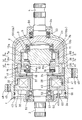
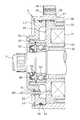
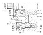
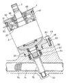
- Sectional drawing which shows the rotation transmission device which concerns on 1st Embodiment of this invention.
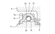
- Sectional view taken along line II-II of FIG. An enlarged cross-sectional view of the vicinity of a pair of rollers showing a state in which the roller cage shown in FIG. 2 has moved from the disengagement position to the engagement position.
- Sectional view taken along line IV-IV of FIG. Sectional view along the VV line of FIG.
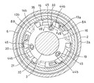
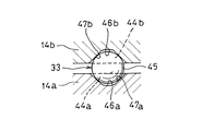
- Sectional view taken along the line VII-VII of FIG. The relative rotation of the first split cage and the second split cage shown in FIG.
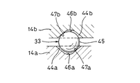
- FIG. 7A causes the ball to roll in the direction away from the deepest portion of each inclined groove in the circumferential direction, and the first split cage and the second split cage Cross-sectional view showing a state in which the axial spacing of the split cage is expanded.
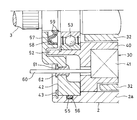
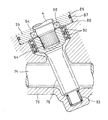
- FIG. 8 shows a modified example in which the position of the ring groove accommodating the O-ring in FIG. 8 is changed from the outer peripheral surface of the cover member to the inner peripheral surface of the large-diameter tubular portion of the case.
- FIG. 1 shows a rotation transmission device 1 according to a first embodiment of the present invention.
- the rotation transmission device 1 includes a tubular case 2 with both ends open, an input shaft 3 for inputting rotation from the outside, an output shaft 4 for outputting rotation transmitted from the input shaft 3, and an input shaft 3. It is connected to the inner ring 5 provided in the housing portion of the input shaft 3 in the case 2 so as to rotate integrally with the output shaft 4 and to the housing portion of the output shaft 4 in the case 2 so as to rotate integrally with the output shaft 4.
- the outer ring 6 is provided, a plurality of rollers 7a and 7b incorporated between the inner circumference of the outer ring 6 and the outer circumference of the inner ring 5, and a roller cage 8 for holding the rollers 7a and 7b.
- the case 2 is a connection that connects a cylindrical large-diameter cylinder portion 2a, a cylindrical small-diameter cylinder portion 2b having an inner diameter smaller than the inner diameter of the large-diameter cylinder portion 2a, and a large-diameter cylinder portion 2a and a small-diameter cylinder portion 2b. It is composed of a part 2c.
- the end of the large-diameter cylinder 2a opposite to the small-diameter cylinder 2b side and the end of the small-diameter cylinder 2b opposite to the large-diameter cylinder 2a are open.
- the large-diameter tubular portion 2a, the small-diameter tubular portion 2b, and the connecting portion 2c are formed as a seamless integrated member.
- the input shaft 3 and the inner ring 5 are formed as a seamless integrated member so that both can rotate integrally.
- the input shaft 3 and the inner ring 5 may be formed as separate members, and may be connected by serration fitting or the like so that both of them rotate integrally.
- the output shaft 4 is arranged side by side on the same straight line as the input shaft 3.
- One end of the output shaft 4 is housed in the case 2, and the other end is provided so as to project from the open end of the small diameter tubular portion 2b of the case 2.
- the output shaft 4 and the outer ring 6 are formed as a seamless integrated member so that both can rotate integrally.
- the outer ring 6 is a portion formed in an annular shape surrounding the inner ring 5.
- the outer ring 6 and the output shaft 4 are integrally formed, but the output shaft 4 and the outer ring 6 may be formed as separate members and connected by serration fitting or the like so that both of them rotate integrally.
- An intermediate bearing 9 that connects the inner ring 5 and the outer ring 6 so as to be relatively rotatable is incorporated between the inner ring 5 and the outer ring 6.
- a plurality of cam surfaces 10 are provided on the outer periphery of the inner ring 5 at equal intervals in the circumferential direction.
- the cam surface 10 includes a front cam surface 10a and a rear cam surface 10b arranged behind the front cam surface 10a in the normal rotation direction of the inner ring 5.
- a cylindrical surface 11 facing the cam surface 10 in the radial direction is provided on the inner circumference of the outer ring 6.
- a pair of rollers 7a and 7b facing each other in the circumferential direction with a roller release spring 12 sandwiched between the cam surface 10 and the cylindrical surface 11 are incorporated.
- the front roller 7a in the forward rotation direction is incorporated between the front cam surface 10a and the cylindrical surface 11
- the rear roller 7b in the forward rotation direction is the rear cam surface 10b and the cylindrical surface 11. It is built in between.
- the roller release spring 12 presses the rollers 7a and 7b in a direction that widens the distance between the pair of rollers 7a and 7b.
- the front cam surface 10a is formed so that the radial distance from the cylindrical surface 11 gradually decreases from the position of the roller 7a toward the front in the normal rotation direction.
- the rear cam surface 10b is formed so that the radial distance from the cylindrical surface 11 gradually decreases from the position of the roller 7b toward the rear in the normal rotation direction.
- the front cam surface 10a and the rear cam surface 10b are formed so as to be separate planes inclined in opposite directions, but the front cam surface 10a and the rear cam surface 10b are positive on a single plane. It is also possible to form them on the same plane so that the front side portion in the rolling direction is the front cam surface 10a and the rear side portion is the rear cam surface 10b.
- the front cam surface 10a and the rear cam surface 10b can be curved, but if they are flat as shown in FIG. 3, the processing cost can be reduced.
- the roller cage 8 is a first split retainer that supports one of the pair of rollers 7a and 7b facing each other in the circumferential direction with the roller release spring 12 in between. It consists of 8A and a second split cage 8B that supports the other roller 7b.
- the first split cage 8A and the second split cage 8B are supported so as to be relatively rotatable, and the pair of rollers 7a and 7b are supported so that the distance between the pair of rollers 7a and 7b changes according to the relative rotation. Are individually supported.
- the first split cage 8A has a plurality of pillar portions 13a arranged at intervals in the circumferential direction, and an annular flange portion 14a connecting the ends of these pillar portions 13a.
- the second split cage 8B also has a plurality of pillar portions 13b arranged at intervals in the circumferential direction, and an annular flange portion 14b that connects the ends of these pillar portions 13b to each other.
- the pillar portion 13a of the first split cage 8A and the pillar portion 13b of the second split cage 8B have a pair of rollers 7a and 7b facing each other in the circumferential direction with the roller separation spring 12 in between from both sides in the circumferential direction. It is inserted between the inner circumference of the outer ring 6 and the outer circumference of the inner ring 5 so as to be sandwiched.
- the flange portion 14a of the first split cage 8A and the flange portion 14b of the second split cage 8B are such that the flange portion 14b of the second split cage 8B is the first split cage. It is arranged so as to face the inner ring 5 in the axial direction with respect to the flange portion 14a of the 8A. Then, in the flange portion 14b of the second split cage 8B, notches 15 (see FIG. 6) for avoiding interference with the pillar portion 13a of the first split cage 8A are spaced apart in the circumferential direction. There are multiple.
- the inner circumference of the flange portion 14a of the first split cage 8A and the inner circumference of the flange portion 14b of the second split cage 8B are rotatably supported by a cylindrical surface 16 provided on the outer circumference of the input shaft 3. ing.
- the first split cage 8A and the second split cage 8B engage the rollers 7a and 7b between the cylindrical surface 11 and the cam surface 10 by widening the distance between the pair of rollers 7a and 7b.
- Disengagement of the rollers 7a and 7b between the cylindrical surface 11 and the cam surface 10 by narrowing the distance between the engaging position (see FIG. 3) and the pair of rollers 7a and 7b. It can be moved to and from the position (see FIG. 2).
- the flange portion 14a of the first split cage 8A is supported in the axial direction by the annular convex portion 18 provided on the outer periphery of the input shaft 3 via the thrust bearing 17, whereby the movement in the axial direction is restricted. There is.
- a spring holder 19 is fixed to the side surface of the inner ring 5.
- the spring holder 19 has a stopper piece 20 located between both pillar portions 13a and 13b facing each other in the circumferential direction with a pair of rollers 7a and 7b sandwiched between them.
- the edges on both sides of the stopper piece 20 receive the pillar portions 13a and 13b.
- roller release spring 12 between the pair of rollers 7a and 7b is prevented from being excessively compressed and damaged, and each roller 7a with respect to the inner ring 5 when the distance between the pair of rollers 7a and 7b is narrowed is prevented.
- 7b can be fixed in position.
- the spring holder 19 has a spring holding piece 21 that holds the roller release spring 12.
- the spring holding piece 21 is integrally formed with the stopper piece 20 so as to extend axially between the inner circumference of the outer ring 6 and the outer circumference of the inner ring 5.
- the spring holding piece 21 is arranged so as to face the spring support surface 22 (see FIG. 3) formed between the front cam surface 10a and the rear cam surface 10b on the outer periphery of the inner ring 5 in the radial direction.
- a recess 23 for accommodating the roller release spring 12 is formed on the surface of the spring holding piece 21 facing the spring support surface 22.
- the roller release spring 12 is a compression coil spring.
- the spring holding piece 21 regulates the movement of the roller release spring 12 by the recess 23, thereby preventing the roller release spring 12 from falling off in the axial direction from between the inner circumference of the outer ring 6 and the outer circumference of the inner ring 5. ing.
- annular electromagnet 30 As shown in FIG. 1, between the inner circumference of the large-diameter tubular portion 2a of the case 2 and the outer circumference of the input shaft 3, an annular electromagnet 30 and a support so as to move in the axial direction by energization of the electromagnet 30.
- the armature 31 is moved, the rotor 32 arranged between the electromagnet 30 and the armature 31, and the armature 31 are moved in the axial direction by the roller cage 8 (first split cage 8A and second split cage 8B).
- the armature 31 has an annular disk portion 34 and a cylindrical portion 35 integrally formed so as to extend axially from the outer circumference of the disk portion 34.
- a cylindrical portion 36 integrally formed so as to extend in the axial direction from the outer periphery of the flange portion 14b of the second split cage 8B is press-fitted into the cylindrical portion 35 of the armature 31, and by this press-fitting, the armature 31 is pressed into the third. It is connected to the second split cage 8B so as to move integrally with the second split cage 8B in the axial direction.
- the armature 31 is supported by a cylindrical surface 37 provided on the annular convex portion 18 on the outer periphery of the input shaft 3 so as to be rotatable and axially movable.
- the armature 31 is supported in the axial direction at two positions separated from each other in the axial direction (that is, the inner circumference of the armature 31 and the inner circumference of the second split cage 8B) so that the armature 31 can move in the posture of the armature 31. Is prevented from tilting in the direction perpendicular to the axis.
- the rotor 32 is supported on the outer circumference of the input shaft 3 so as not to move relative to either the axial direction or the circumferential direction by fitting the rotor 32 on the outer circumference of the input shaft 3 with a tightening margin.
- the rotor 32 and the armature 31 are made of a magnetic material (iron, silicon steel, etc.).
- a plurality of elongated holes 38 that penetrate the rotor 32 in the axial direction and extend in the circumferential direction are formed at intervals in the circumferential direction.
- the electromagnet 30 has a field core 40 made of an annularly formed magnetic material and a solenoid coil 41 wound around the field core 40.
- the field core 40 is fitted to the inner circumference of the large diameter tubular portion 2a of the case 2.
- the electromagnet 30 forms a magnetic path through the field core 40, the rotor 32, and the armature 31 by energizing the solenoid coil 41, and attracts the armature 31 to the rotor 32.
- a cover member 42 of the ring plate is fitted on the inner circumference of the open end of the large diameter tubular portion 2a so as to face the electromagnet 30 in the axial direction.
- the cover member 42 is incorporated into the field core 40 so as to abut against it in the axial direction.
- the cover member 42 is prevented from coming off from the case 2 by a retaining ring 43 attached to the inner circumference of the open end of the large-diameter tubular portion 2a.
- the ball lamp mechanism 33 is provided with an inclination of the flange portion 14a of the first split cage 8A on the surface facing the flange portion 14b of the second split cage 8B.
- the groove 44a and the inclined groove 44b provided on the surface of the flange portion 14b of the second split cage 8B facing the flange portion 14a of the first split retainer 8A are incorporated between the inclined groove 44a and the inclined groove 44b. It consists of a ball 45.
- the inclined groove 44a and the inclined groove 44b are formed so as to extend in the circumferential direction, respectively.
- the inclined groove 44a has a shape having a groove bottom 47a inclined so as to gradually become shallower in one direction in the circumferential direction from the deepest portion 46a having the deepest axial depth, and the inclined groove 44b also has an axial direction.
- the shape has a groove bottom 47b that is inclined so as to gradually become shallower in the other direction in the circumferential direction from the deepest portion 46b having the deepest depth.
- the balls 45 are arranged so as to be sandwiched between the groove bottom 47a and the groove bottom 47b.
- the balls 45 move in the inclined grooves 44a, respectively.
- the first split cage 8A and the second split cage 8B rotate relative to each other, and as a result, the pillar portions 13a and the first split cage 8A of the first split cage 8A are rotated.
- the pillar portion 13b of the split cage 8B of 2 operates so as to move in a direction of narrowing the distance between the pair of rollers 7a and 7b.
- the armature 31 is urged away from the rotor 32 by the force of the roller release spring 12. That is, the force with which the roller separation spring 12 shown in FIG. 2 presses the rollers 7a and 7b in the direction of widening the distance between the pair of rollers 7a and 7b is applied to the first split cage 8A and the second split cage 8B. introduce.
- the circumferential force received by the first split cage 8A and the second split cage 8B is axially distant from the rotor 32 by the ball lamp mechanism 33 shown in FIGS. 6 and 7A and 7B. It is converted into force and transmitted to the second split cage 8B.
- the large-diameter tubular portion 2a is formed with a fixing flange 48 that projects radially outward from the outer circumference of the large-diameter tubular portion 2a.
- An axial through hole 49 is formed in the fixing flange 48, and a bolt (not shown) is inserted into the through hole 49 and tightened to support the fixing flange 48 (for example, the rack housing 75 shown in FIG. 15). ) Can be fixed.
- a protrusion 51 that engages with the axial groove 50 formed on the inner circumference of the large-diameter tubular portion 2a is formed, and the protrusion 51 and the axial groove 50 are formed.
- the field core 40 is prevented from rotating in the case 2 by the engagement of.
- a bearing fitting cylinder 52 is fixedly provided on the surface of the field core 40 opposite to the side on which the armature 31 (see FIG. 1) is attracted.
- the bearing fitting cylinder 52 may be provided by fixing the bearing fitting cylinder 52 formed separately from the field core 40 to the field core 40 by welding or the like, and the bearing fitting cylinder 52 is jointed with the field core 40. It may be formed integrally without.
- An input shaft bearing 53 that rotatably supports the input shaft 3 is incorporated between the inner circumference of the bearing fitting cylinder 52 and the outer circumference of the input shaft 3.
- the input shaft bearing 53 is a sealed bearing (in the figure, a deep groove ball with a seal) in which grease is sealed in an annular bearing space between the inner ring and the outer ring with bearing seals provided on both sides in the axial direction of a rolling element that rolls between the inner ring and the outer ring. Bearings) can be adopted.
- a retaining ring 54 for preventing the input shaft bearing 53 from coming off is mounted on the inner circumference of the bearing fitting cylinder 52.
- the cover member 42 is an annular plate-shaped member that fits on the inner circumference of the large-diameter tubular portion 2a of the case 2, and is made of aluminum.
- the outer circumference of the cover member 42 and the inner circumference of the large-diameter tubular portion 2a are sealed with a rubber O-ring 55.
- the O-ring 55 is mounted on a ring groove 56 formed on the outer periphery of the cover member 42, and is incorporated in a compressed state between the inner surface of the ring groove 56 and the cylindrical inner peripheral surface of the large-diameter tubular portion 2a. .. As shown in FIG.
- the O-ring 55 is attached to the ring groove 56 formed on the inner circumference of the large-diameter tubular portion 2a, and is compressed between the inner surface of the ring groove 56 and the cylindrical outer peripheral surface of the cover member 42. It may be incorporated in the state of the above.
- the oil seal 57 has an annular core metal 58 made of a metal plate and a rubber seal lip 59 provided by adhering to the core metal 58.
- the seal lip 59 is slidably in contact with the outer periphery of the input shaft 3 in the circumferential direction.
- the cover member 42 is formed with a through hole 61 through which a lead wire 60 that supplies electric power to the electromagnet 30 is inserted.
- a rubber grommet 62 that seals between the inner circumference of the through hole 61 and the outer circumference of the lead wire 60 is attached to the through hole 61.
- the grommet 62 is a member in which a large outer diameter portion that locks to the opening edge of the through hole 61 is formed at both ends of a tubular portion that closes an annular gap between the inner circumference of the through hole 61 and the outer circumference of the lead wire 60.
- an output shaft bearing 63 that rotatably supports the output shaft 4 is incorporated in the inner circumference of the small diameter tubular portion 2b of the case 2. Similar to the input shaft bearing 53, the output shaft bearing 63 has bearing seals provided on both sides of the rolling element that rolls between the inner ring and the outer ring in the axial direction, and has a seal in which grease is sealed in the annular bearing space between the inner ring and the outer ring. Bearings (deep groove ball bearings with seals in the figure) can be used. Further, on the inner circumference of the small-diameter tubular portion 2b, an inward-facing annular projection 64 is provided on the side far from the large-diameter tubular portion 2a (see FIG. 1) with respect to the position where the output shaft bearing 63 is fitted. An elastic member 65 is incorporated between the annular protrusion 64 and the output shaft bearing 63. The elastic member 65 is incorporated in a state of being compressed in the axial direction.
- the output shaft seal member 66 is an oil seal having an annular core metal 67 made of a metal plate and a rubber seal lip 68 provided by adhering to the core metal 67.
- the seal lip 68 is slidably in contact with the outer periphery of the output shaft 4 in the circumferential direction.
- the rotation transmission device 1 when the electromagnet 30 is energized, the rotation transmission device 1 is in an disengaged state (idling state) in which rotation transmission between the input shaft 3 and the output shaft 4 is cut off. .. That is, when the electromagnet 30 is energized, the armature 31 is attracted to the rotor 32, and in conjunction with the operation of the armature 31, the flange portion 14b of the second split cage 8B becomes the flange portion 14a of the first split cage 8A. Move in the axial direction toward. At this time, the ball 45 of the ball lamp mechanism 33 rolls toward the deepest portions 46a and 46b of the inclined grooves 44a and 44b, so that the first split cage 8A and the second split cage 8B rotate relative to each other.
- the pillar portion 13a of the first split cage 8A and the pillar portion 13b of the second split cage 8B are paired.
- the rollers 7a and 7b are pressed in the direction in which the distance between the rollers 7a and 7b is narrowed, and as a result, the front roller 7a in the normal rotation direction is in an engagement standby state (the front roller 7a and the cylindrical surface 11 in the normal rotation direction).
- the roller 7a immediately engages between the cylindrical surface 11 and the front cam surface 10a), and the rear side in the normal rotation direction is released.
- the roller 7b is in an engagement standby state (there is a minute gap between the roller 7b on the rear side in the normal rotation direction and the cylindrical surface 11, but when the input shaft 3 rotates in the forward rotation direction, the roller 7b immediately moves to the cylindrical surface 11 and the rear cam.
- the state of being engaged between the surfaces 10b) is also released. In this state, even if rotation is input to the input shaft 3, the rotation is not transmitted from the input shaft 3 to the outer ring 6, and the input shaft 3 idles.
- the rotation transmission device 1 is in an engaged state in which rotation is transmitted between the input shaft 3 and the output shaft 4. That is, when the energization of the electromagnet 30 is stopped, the armature 31 moves axially in the direction of separation from the rotor 32 by the force of the roller separation spring 12. At this time, due to the force of the roller separation spring 12 that presses the rollers 7a and 7b in the direction in which the distance between the pair of rollers 7a and 7b is widened, the front roller 7a in the forward rotation direction is formed into a cylinder on the inner circumference of the outer ring 6.
- the roller 7b which is engaged between the surface 11 and the front cam surface 10a on the outer circumference of the input shaft 3 and is on the rear side in the normal rotation direction, is formed on the cylindrical surface 11 on the inner circumference of the outer ring 6 and the outer circumference of the input shaft 3. It is in a state of being engaged with the rear cam surface 10b. In this state, when the input shaft 3 rotates in the forward rotation direction, the rotation is transmitted from the input shaft 3 to the outer ring 6 via the roller 7b on the rear side in the forward rotation direction. Further, when the input shaft 3 rotates in the reverse direction, the rotation is transmitted from the input shaft 3 to the outer ring 6 via the roller 7a on the front side in the forward rotation direction.
- the cover member 42 is arranged so as to face the electromagnet 30 in the axial direction and is made of aluminum having excellent thermal conductivity. It effectively prevents the temperature of the electromagnet 30 arranged in the case 2 from rising due to heat dissipation from the case 2, and prevents the attractive force of the armature 31 from the electromagnet 30 from falling due to the temperature rise of the electromagnet 30. It is possible. Further, since aluminum is a non-magnetic material, it is possible to prevent the magnetic flux generated from the electromagnet 30 from being absorbed by the cover member 42, and it is also possible to prevent a decrease in the attractive force of the electromagnet 30 due to magnetic flux leakage.
- the rotation transmission device 1 uses an oil seal 57 having a core metal 58 and a rubber seal lip 59 as an inner seal member for sealing between the inner circumference of the cover member 42 and the outer circumference of the input shaft 3. Therefore, rather than using an O-ring or the like as the inner seal member, it is more reliable that foreign matter such as muddy water enters the inside of the rotation transmission device 1 through between the relative rotating input shaft 3 and the cover member 42. It is possible to prevent it.
- the rotation transmission device 1 employs an O-ring 55 as an outer sealing member for sealing between the outer circumference of the cover member 42 and the inner circumference of the large-diameter tubular portion 2a, a case that does not involve relative rotation. It is possible to seal between the open end of 2 and the cover member 42 at low cost.
- an annular core metal 95 made of a metal plate and the core metal 95 are adhered to each other.
- An oil seal 97 having a rubber seal lip 96 provided therein may be used. In this way, more reliable sealing is possible.
- the core metal 95 is press-fitted into the inner circumference of the large-diameter tubular portion 2a, and the seal lip 59 is in contact with the outer circumference of the cover member 42 with a tightening margin.
- the oil seal 57 that seals between the inner circumference of the cover member 42 and the outer circumference of the input shaft 3 may have a garter spring 69 that tightens the seal lip 59 from the outer diameter side.
- a stainless steel slinger 70 with which the seal lip 59 is in sliding contact may be adopted.
- the slinger 70 is a member having an L-shaped cross section that is fitted to the outer periphery of the input shaft 3 with a tightening allowance.
- FIG. 13 shows the rotation transmission device 1 of the second embodiment.
- the parts corresponding to the first embodiment are designated by the same reference numerals and the description thereof will be omitted.
- a cylindrical bearing fitting surface 71 into which the input shaft bearing 53 is fitted is formed on the inner circumference of the aluminum cover member 42.
- the axial length of the bearing fitting surface 71 is larger than the axial width of the input shaft bearing 53. Therefore, an axial gap is formed between the input shaft bearing 53 and the field core 40, and the input shaft bearing 53 is not in contact with the field core 40.
- the bearing fitting surface 71 is arranged on the inner circumference of the cylindrical portion 72 formed on the cover member 42.
- the cylindrical portion 72 is inserted into the inner circumference of the bearing fitting cylinder 52 extending axially from the field core 40 with a tightening margin. As a result, it is possible to prevent the input shaft bearing 53 from coming into contact with the field core 40 while supporting the input shaft bearing 53 with high rigidity.
- the axial end face of the cylindrical portion 72 abuts on the field core 40.
- the electromagnet Since the input shaft bearing 53 is arranged on the inner circumference of the cover member 42 made of aluminum, which is a non-magnetic material, in non-contact with the field core 40 of the electromagnet 30, the electromagnet It is possible to prevent the magnetic flux generated from the 30 from leaking to the input shaft 3 through the input shaft bearing 53, and to improve the attractive force of the armature 31 by the electromagnet 30.
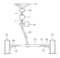
- the vehicle steering device includes a rack 74 connected to a pair of left and right steering wheels 73, a rack housing 75 that movably accommodates the rack 74, and a pinion 76 that meshes with the rack 74 ( (See FIG. 15), a rotation transmission device 1 detachably fixed to the rack housing 75, a steering wheel 77 steered by the driver, and a steering shaft 78 that transmits the rotation of the steering wheel 77 to the rotation transmission device 1.
- a rack 74 connected to a pair of left and right steering wheels 73
- a rack housing 75 that movably accommodates the rack 74
- a pinion 76 that meshes with the rack 74 (See FIG. 15)
- a rotation transmission device 1 detachably fixed to the rack housing 75
- a steering wheel 77 steered by the driver
- a steering shaft 78 that transmits the rotation of the steering wheel 77 to the rotation transmission device 1.
- Both ends of the rack 74 are connected to the knuckle arms 80 of the left and right steering wheels 73 via ball joints 79.
- the knuckle arms 80 rotate according to the movement, and the steering wheels The direction of 73 is changed.
- a steering motor 81 that drives the rack 74 to the left and right is attached to the rack housing 75.
- the mounting position of the steering motor 81 with respect to the rack housing 75 and the mounting position of the rotation transmission device 1 with respect to the rack housing 75 are separated from each other.
- a reaction force motor 82 that applies a steering reaction force to the steering wheel 77 is attached to the end of the steering shaft 78 on the steering wheel 77 side.
- the reaction force motor 82 has a built-in steering angle sensor that detects the steering angle of the steering wheel 77.
- the fixing flange 48 is superposed on the seat surface 83 formed in the rack housing 75, and the bolt 84 is inserted into the through hole 49 formed in the fixing flange 48.
- the rack housing 75 has a cylindrical positioning fitting surface 86 that fits with a cylindrical surface 85 formed on the outer periphery of the small diameter tubular portion 2b of the case 2.
- the outer peripheral cylindrical surface 85 of the small diameter tubular portion 2b and the positioning fitting surface 86 are sealed with an O-ring 87.
- a dust cover 88 is fixed to the input shaft 3 of the rotation transmission device 1.
- the dust cover 88 has an inner cylinder portion 89 that is fitted to the outer periphery of a portion of the input shaft 3 protruding from the case 2 with a tightening margin, and a large diameter cylinder of the case 2 that extends outward in the radial direction from one end of the inner cylinder portion 89. It has a flange portion 90 that covers the open end of the portion 2a, and a cylindrical skirt portion 91 that extends axially from the outer circumference of the flange portion 90 along the outer circumference of the large diameter tubular portion 2a.
- a labyrinth gap is formed between the inner circumference of the skirt portion 91 and the outer circumference of the large-diameter tubular portion 2a.
- the labyrinth gap is a minute gap having a radial width of less than 1.0 mm (preferably 0.5 mm or less).
- the large-diameter tubular portion 2a of the case 2 is formed with a through hole 61 through which a lead wire 60 for supplying electric power to the electromagnet 30 is inserted.
- a rubber grommet 62 that seals between the inner circumference of the through hole 61 and the outer circumference of the lead wire 60 is attached to the through hole 61.
- the configuration of the grommet 62 is the same as that of the above embodiment.
- the pinion 76 is rotatably supported by the first pinion support bearing 92 and the second pinion support bearing 93 assembled to the rack housing 75.
- the first pinion support bearing 92 adopts a double-row deep groove ball bearing in the figure
- the second pinion support bearing 93 adopts a needle roller bearing in the figure.
- the first pinion support bearing 92 and the second pinion support bearing 93 support the pinion 76 on both sides sandwiching the meshing portion of the pinion 76 with respect to the rack 74.
- the bearing that supports the pinion 76 on the side closer to the rotation transmission device 1 than the meshing portion of the pinion 76 with respect to the rack 74 is the first pinion support bearing 92, and the rotation transmission device is closer to the meshing portion of the pinion 76 with respect to the rack 74.
- the bearing that supports the pinion 76 on the side far from 1 is the second pinion support bearing 93.
- the first pinion support bearing 92 is axially sandwiched and fixed between the small diameter tubular portion 2b of the case 2 of the rotation transmission device 1 and the rack housing 75.
- a detent fitting portion 94 is provided so that the output shaft 4 rotates integrally with the pinion 76.
- the detent fitting portion 94 may employ a key and a keyway, but if a spline shaft portion and a spline hole that are fitted to each other are adopted as shown in the figure, the output shaft 4 and the pinion 76 Easy to connect.
- the spline shaft portion is provided on the output shaft 4 side and the spline hole is provided on the pinion 76 side, but the spline shaft portion and the spline hole can be reversed. Is.
- the vehicle steering device of the embodiment shown in FIG. 14 keeps the rotation transmission device 1 from the input shaft 3 by keeping the electromagnet 30 (see FIG. 15) of the rotation transmission device 1 energized during normal running of the vehicle. It is used as an idling state in which the transmission of rotation to the output shaft 4 is cut off. At this time, the steering angle of the steering wheel 77 is detected by the steering angle sensor built in the reaction force motor 82, and the steering angle of the steering wheel 77 and the steering angle of the steering wheel 73 change correspondingly. The steering motor 81 is operated. On the other hand, in the event of an abnormality such as when the power supply is lost, the energization of the electromagnet 30 (see FIG.
- a steering shaft 78 that transmits steering force from a steering wheel 77 to a rack 74 for steering a vehicle is a portion where foreign matter such as muddy water is hard to adhere. It was often used by assembling it at the center position of.
- a reaction force motor 82, a rotation transmission device 1, and a steering motor 81 are attached to the steering shaft 78 in this order from the side of the steering wheel 77 toward the side of the rack housing 75.
- the rotation transmission device 1 accommodates a portion where foreign matter such as muddy water may adhere (specifically, a rack 74 for vehicle steering).
- the rack housing 75 is assembled so as to be exposed on the lower side of the vehicle). In this case, it is necessary to prevent foreign matter such as muddy water from entering the inside of the rotation transmission device 1.
- the large-diameter tubular portion 2a of the case 2 is on the upper side and the small-diameter tubular portion 2b of the case 2 is on the lower side.
- the upper surface of the cover member 42 fitted to the open end of the large diameter tubular portion 2a of the case 2 is covered with the dust cover 88, so that the outer seal member on the outer peripheral side of the cover member 42 ( It is possible to prevent foreign matter such as muddy water from accumulating in the vicinity of the O-ring 55) and the inner seal member (oil seal 57) on the inner peripheral side of the cover member 42, and more effectively inside the rotation transmission device 1. It is possible to prevent foreign matter from entering the surface.
- the cover member 42, the O-ring 55, and the oil seal 57 are between the inner circumference of the opening end of the large-diameter tubular portion 2a of the case 2 of the rotation transmission device 1 and the outer circumference of the input shaft 3. Since it is sealed with and, even if it is used in an environment where foreign matter such as muddy water may adhere, it is possible to prevent the foreign matter from entering the inside of the rotation transmission device 1.
- the rack housing 75 is provided with a cylindrical positioning fitting surface 86 that fits with the cylindrical surface 85 formed on the outer periphery of the small diameter tubular portion 2b of the case 2, the rack housing When the rotation transmission device 1 is assembled to the 75, it is easy to prevent the pinion 76 and the output shaft 4 from being misaligned.
- this vehicle steering device has an O-ring 87 that seals between the cylindrical surface 85 on the outer periphery of the small diameter tubular portion 2b and the positioning fitting surface 86, after the rotation transmission device 1 is assembled to the rack housing 75, It is possible to effectively prevent foreign matter such as muddy water from entering the inside of the rack housing 75 through the gap between the small diameter tubular portion 2b of the case 2 of the rotation transmission device 1 and the rack housing 75.
- the first pinion support bearing 92 and the second pinion support bearing 93 are provided so as to support the pinion 76 on both sides of the pinion 76 with the meshing portion with respect to the rack 74 sandwiched between them.
- the support of the pinion 76 is stable, and the meshing accuracy of the pinion 76 with respect to the rack 74 is high.
- the first pinion support bearing 92 is fixed by sandwiching it in the axial direction between the small diameter tubular portion 2b of the case 2 of the rotation transmission device 1 and the rack housing 75, so that the pinion support is supported. Axial rattling of the bearing is prevented, and the meshing accuracy of the pinion 76 with respect to the rack 74 can be effectively improved.
- rollers 7a and 7b are used as the engaging elements to be incorporated between the inner circumference of the outer ring 6 and the outer circumference of the inner ring 5, but the present invention employs a ball or a sprag as the engaging element. The same can be applied to the rotation transmission device 1 that has been used.
Landscapes
- Engineering & Computer Science (AREA)
- General Engineering & Computer Science (AREA)
- Mechanical Engineering (AREA)
- Chemical & Material Sciences (AREA)
- Combustion & Propulsion (AREA)
- Transportation (AREA)
- Physics & Mathematics (AREA)
- Electromagnetism (AREA)
- Power Steering Mechanism (AREA)
- Sealing Of Bearings (AREA)
- General Details Of Gearings (AREA)
- Steering Controls (AREA)
- Sealing With Elastic Sealing Lips (AREA)
- Gasket Seals (AREA)
Abstract
外輪(6)の内周と内輪(5)の外周との間に組み込まれたローラ(7a,7b)と、電磁石(30)の通電により軸方向に移動するように支持されたアーマチュア(31)と、アーマチュア(31)の軸方向の移動を、ローラ保持器(8)が係合位置から係合解除位置に移動する動作に変換するボールランプ機構(33)とを有する回転伝達装置において、アルミ製の環板のカバー部材(42)とOリング(55)とオイルシール(57)とを設ける。
Description
この発明は、回転の伝達と遮断の切り換えに用いられる回転伝達装置、およびその回転伝達装置を用いた車両用操舵装置に関する。
入力軸から出力軸に回転が伝達する状態と、その回転の伝達を遮断する状態とを切り換えるために用いられる回転伝達装置として、例えば、特許文献1に記載のものが知られている。
特許文献1に記載の回転伝達装置は、両端が開放した筒状のケースと、ケースに一端が収容された状態に配置された入力軸と、ケースに一端が収容された状態で入力軸と同一直線上に並んで配置された出力軸と、入力軸のケース内への収容部分に設けられた内輪と、出力軸と一体に回転するように出力軸のケース内への収容部分に接続して設けられた外輪と、外輪の内周の円筒面と内輪の外周のカム面との間に組み込まれた一対のローラと、その一対のローラを保持するローラ保持器とを有する。
ローラ保持器は、相対回転可能に支持された2個の分割保持器からなる。この2個の分割保持器は、前記一対のローラを外輪の内周の円筒面と内輪の外周のカム面との間に係合させる係合位置と、その各ローラの係合を解除させる係合解除位置との間で移動可能となっている。
回転伝達装置のケースは、円筒状の大径筒部と、大径筒部の内径よりも小さい内径をもつ円筒状の小径筒部と、大径筒部と小径筒部を連結する連結部とが継ぎ目の無い一体に形成された筒状の部材である。
大径筒部の内周と入力軸の外周との間には、環状の電磁石と、その電磁石の通電により軸方向に移動するように支持されたアーマチュアと、アーマチュアの軸方向の移動を、2個の分割保持器が係合位置から係合解除位置に移動する動作に変換するボールランプ機構とが組み込まれている。
ところで、上記の回転伝達装置を自動車に組み付ける場合、従来は、泥水などの異物が付着しにくい部位(例えば、ステアリングホイールから車両操舵用のラックに操舵力を伝えるステアリングシャフトの中央位置)に組み付けて使用されることが多かった。
これに対し、本願の発明者は、上記の回転伝達装置を、泥水などの異物が付着するおそれのある部位(例えば、車両操舵用のラックを収容するラックハウジング。ラックハウジングは、車両下側に露出した状態に組み付けられる)に直接取り付けることを検討した。そして、発明者は、回転伝達装置に泥水などの異物が付着したときに、その異物が回転伝達装置の内部に侵入するのを防ぐため、回転伝達装置のケースの大径筒部の開口端を完全に密閉するように設計変更し、その試作評価を行なった。
その結果、回転伝達装置のケースの大径筒部の開口端を完全に密閉したときに、回転伝達装置の動作が不安定になるおそれがあることが分かった。すなわち、回転伝達装置のケースの大径筒部の開口端を完全に密閉すると、ケース内に熱がこもりやすくなり、ケース内に配置された電磁石の温度が上昇しやすくなる。そして、電磁石が高温になると、電磁石に通電したときのアーマチュアの吸引力が低下することから、電磁石に通電しても、ローラ保持器が係合位置から係合解除位置に移動せず、回転伝達装置の動作が不安定となるおそれがあることが分かった。
この発明が解決しようとする課題は、泥水などの異物が付着するおそれのある環境で安定して動作する回転伝達装置を提供することである。
上記の課題を解決するため、この発明では、以下の構成の回転伝達装置を提供する。
円筒状の大径筒部と、前記大径筒部の内径よりも小さい内径をもつ円筒状の小径筒部と、前記大径筒部と前記小径筒部を連結する連結部とを継ぎ目の無い一体の部材としてもち、前記大径筒部の前記小径筒部側とは反対側の端部と前記小径筒部の前記大径筒部側とは反対側の端部とがそれぞれ開口した筒状のケースと、
一端が前記ケース内に収容され、他端が前記ケースの前記大径筒部の開口端から突出した状態に設けられた入力軸と、
前記入力軸と同一直線上に配置され、一端が前記ケース内に収容され、他端が前記ケースの前記小径筒部の開口端から突出した状態に設けられた出力軸と、
前記入力軸と一体に回転するように前記入力軸のケース内への収容部分に設けられた内輪と、
前記出力軸と一体に回転するように前記出力軸のケース内への収容部分に接続して設けられ、前記内輪を囲む環状に形成された外輪と、
前記外輪の内周と前記内輪の外周との間に組み込まれた係合子と、
前記係合子を前記外輪と前記内輪の間に係合させる係合位置と、前記係合子の係合を解除させる係合解除位置との間で移動可能に支持された係合子保持器と、
前記大径筒部の内周と前記入力軸の外周との間に組み込まれた環状の電磁石と、
前記電磁石の通電により軸方向に移動するように支持されたアーマチュアと、
前記アーマチュアの軸方向の移動を、前記係合子保持器が前記係合位置と係合解除位置のうち一方から他方に移動する動作に変換する動作変換機構と、
前記入力軸を回転可能に支持する入力軸軸受と、
前記出力軸を回転可能に支持する出力軸軸受と、
を有する回転伝達装置において、
前記出力軸の外周と前記小径筒部の開口端の内周との間をシールする出力軸シール部材と、
前記電磁石と軸方向に対向するように前記大径筒部の開口端の内周に嵌め込まれたアルミ製の環板のカバー部材と、
前記カバー部材の外周と前記大径筒部の内周との間をシールする外側シール部材と、
前記カバー部材の内周と前記入力軸の外周との間をシールする内側シール部材とを有することを特徴とする回転伝達装置。
円筒状の大径筒部と、前記大径筒部の内径よりも小さい内径をもつ円筒状の小径筒部と、前記大径筒部と前記小径筒部を連結する連結部とを継ぎ目の無い一体の部材としてもち、前記大径筒部の前記小径筒部側とは反対側の端部と前記小径筒部の前記大径筒部側とは反対側の端部とがそれぞれ開口した筒状のケースと、
一端が前記ケース内に収容され、他端が前記ケースの前記大径筒部の開口端から突出した状態に設けられた入力軸と、
前記入力軸と同一直線上に配置され、一端が前記ケース内に収容され、他端が前記ケースの前記小径筒部の開口端から突出した状態に設けられた出力軸と、
前記入力軸と一体に回転するように前記入力軸のケース内への収容部分に設けられた内輪と、
前記出力軸と一体に回転するように前記出力軸のケース内への収容部分に接続して設けられ、前記内輪を囲む環状に形成された外輪と、
前記外輪の内周と前記内輪の外周との間に組み込まれた係合子と、
前記係合子を前記外輪と前記内輪の間に係合させる係合位置と、前記係合子の係合を解除させる係合解除位置との間で移動可能に支持された係合子保持器と、
前記大径筒部の内周と前記入力軸の外周との間に組み込まれた環状の電磁石と、
前記電磁石の通電により軸方向に移動するように支持されたアーマチュアと、
前記アーマチュアの軸方向の移動を、前記係合子保持器が前記係合位置と係合解除位置のうち一方から他方に移動する動作に変換する動作変換機構と、
前記入力軸を回転可能に支持する入力軸軸受と、
前記出力軸を回転可能に支持する出力軸軸受と、
を有する回転伝達装置において、
前記出力軸の外周と前記小径筒部の開口端の内周との間をシールする出力軸シール部材と、
前記電磁石と軸方向に対向するように前記大径筒部の開口端の内周に嵌め込まれたアルミ製の環板のカバー部材と、
前記カバー部材の外周と前記大径筒部の内周との間をシールする外側シール部材と、
前記カバー部材の内周と前記入力軸の外周との間をシールする内側シール部材とを有することを特徴とする回転伝達装置。
このようにすると、回転伝達装置のケースの小径筒部の開口端の内周と出力軸の外周との間が、出力軸シール部材でシールされ、回転伝達装置のケースの大径筒部の開口端の内周と入力軸の外周との間が、カバー部材と外側シール部材と内側シール部材とでシールされるので、泥水などの異物が付着するおそれのある環境で使用しても、その異物が回転伝達装置の内部に侵入するのを防ぐことができる。また、カバー部材が、電磁石と軸方向に対向するように配置され、かつ、熱伝導性に優れるアルミで形成されているので、ケース内に配置された電磁石の温度が上昇するのを効果的に防止し、電磁石によるアーマチュアの吸引力が、電磁石の温度上昇により低下するのを防止することができる。さらに、アルミは非磁性材料なので、電磁石から生じる磁束がカバー部材に吸収されるのを防止することができ、磁束漏れによる電磁石の吸引力の低下も防止可能である。
前記電磁石は、前記大径筒部の内周に嵌合する環状に形成された磁性材料からなるフィールドコアと、前記フィールドコアに巻回されたソレノイドコイルとを有する場合、前記カバー部材を、前記フィールドコアに軸方向に突き当てて組み込み、前記カバー部材の内周に、前記入力軸軸受が前記フィールドコアと非接触となるように取り付けると好ましい。
このようにすると、入力軸軸受が、非磁性材料であるアルミ製のカバー部材の内周に電磁石のフィールドコアと非接触に配置されているので、電磁石から生じる磁束が、入力軸軸受を通って入力軸に漏れるのが防止され、電磁石によるアーマチュアの吸引力を向上させることができる。
前記カバー部材の内周に、前記入力軸軸受が嵌合する円筒状の軸受嵌合面を形成し、前記軸受嵌合面の軸方向長さを、前記入力軸軸受の軸方向幅よりも大きく設定することで、前記入力軸軸受を、前記フィールドコアと非接触の配置とすることができる。
このようにすると、軸受嵌合面の軸方向長さが、入力軸軸受の軸方向幅よりも大きいので、入力軸軸受がフィールドコアに接触するのを確実に防止することが可能となる。
前記内側シール部材としては、金属板からなる環状の芯金と、前記芯金に接着して設けられ、前記入力軸の外周に摺接するゴム製のシールリップとを有するオイルシールを採用すると好ましい。
このようにすると、相対回転する入力軸とカバー部材の間を通って泥水などの異物が回転伝達装置の内部に侵入するのを確実に防止することが可能となる。
前記外側シール部材としては、ゴム製のOリングを採用すると好ましい。
このようにすると、相対回転を伴わないケースの開口端とカバー部材の間を低コストでシールすることが可能となる。
前記カバー部材または前記大径筒部に、前記電磁石に電力を供給するリード線が挿通する貫通孔を形成する場合、前記貫通孔に、前記貫通孔の内周と前記リード線の外周との間をシールするゴム製のグロメットを装着すると好ましい。
このようにすると、リード線が挿通する貫通孔を通って泥水などの異物が回転伝達装置の内部に侵入するのを確実に防止することが可能となる。
前記入力軸の前記ケースからの突出部分の外周に締め代をもって嵌合する内筒部と、前記内筒部の一端から径方向外方に延びて前記ケースの大径筒部の開口端を覆うフランジ部と、前記フランジ部の外周から前記大径筒部の外周に沿って軸方向に延びる円筒状のスカート部とを有するダストカバーを更に設けると好ましい。
このようにすると、ケースの大径筒部が上側、ケースの小径筒部が下側となる向きで回転伝達装置を使用するときに、ケースの大径筒部の開口端に嵌め込まれたカバー部材の上面がダストカバーで覆われるので、カバー部材の外周側の外側シール部材や、カバー部材の内周側の内側シール部材の近傍に、泥水などの異物が溜まるのを防止することができ、より効果的に回転伝達装置の内部への異物侵入を防止することが可能となる。
また、この発明では、上記の回転伝達装置を用いた車両用操舵装置として、以下の構成のものを併せて提供する。
左右に移動可能に支持され、その移動に応じて左右一対の転舵輪の向きが変化するように前記一対の転舵輪に両端が接続されるラックと、
前記ラックを移動可能に収容するラックハウジングと、
前記ラックに噛み合うピニオンと、
上記の回転伝達装置と、を有し、
前記回転伝達装置の前記ケースは、前記ラックハウジングに着脱可能に固定され、
前記ピニオンは、前記ラックハウジングに組み付けられたピニオン支持軸受で回転可能に支持され、
前記ケースを前記ラックハウジングから取り外した状態では、前記回転伝達装置の前記出力軸が前記ピニオンから切り離され、前記ケースを前記ラックハウジングに取り付けた状態では、前記出力軸が前記ピニオンと一体に回転するように、前記出力軸と前記ピニオンの相互間に回り止め嵌合部が設けられている車両用操舵装置。
左右に移動可能に支持され、その移動に応じて左右一対の転舵輪の向きが変化するように前記一対の転舵輪に両端が接続されるラックと、
前記ラックを移動可能に収容するラックハウジングと、
前記ラックに噛み合うピニオンと、
上記の回転伝達装置と、を有し、
前記回転伝達装置の前記ケースは、前記ラックハウジングに着脱可能に固定され、
前記ピニオンは、前記ラックハウジングに組み付けられたピニオン支持軸受で回転可能に支持され、
前記ケースを前記ラックハウジングから取り外した状態では、前記回転伝達装置の前記出力軸が前記ピニオンから切り離され、前記ケースを前記ラックハウジングに取り付けた状態では、前記出力軸が前記ピニオンと一体に回転するように、前記出力軸と前記ピニオンの相互間に回り止め嵌合部が設けられている車両用操舵装置。
このようにすると、ピニオンと回転伝達装置の出力軸とが別体に形成されているので、ラックハウジングとラックとピニオンとを組み立てる作業と、回転伝達装置の構成部材を組み立てる作業とを別々に行なった後、ラックハウジングに回転伝達装置を組み付けることが可能であり、組み立て作業性に優れる。
前記ラックハウジングに、前記ケースの前記小径筒部の外周に形成した円筒面と嵌合する円筒状の位置決め嵌合面を設けると好ましい。
このようにすると、ラックハウジングに回転伝達装置を組み付けるときに、ピニオンと出力軸の芯ずれを防止することが容易となる。
前記小径筒部の外周の前記円筒面と前記位置決め嵌合面との間をシールするOリングを更に設けると好ましい。
このようにすると、回転伝達装置をラックハウジングに組み付けた後、泥水などの異物が回転伝達装置のケースの小径筒部とラックハウジングとの隙間を通ってラックハウジングの内部に侵入するのを効果的に防止することが可能となる。
前記ピニオン支持軸受は、前記ピニオンの前記ラックに対する噛み合い部分を間に挟む両側で前記ピニオンを支持するように前記ラックハウジングに複数設けると好ましい。
このようにすると、ピニオンの支持が安定し、ラックに対するピニオンの噛み合い精度を高めることができる。
前記ピニオンの前記ラックに対する噛み合い部分を間に挟む両側に設けた複数の前記ピニオン支持軸受のうち、前記ピニオンの前記ラックに対する噛み合い部分よりも前記回転伝達装置に近い側のピニオン支持軸受を、前記回転伝達装置の前記ケースの小径筒部と前記ラックハウジングとの間で軸方向に挟んで固定することができる。
このようにすると、ピニオン支持軸受の軸方向のがたつきが防止され、ラックに対するピニオンの噛み合い精度を効果的に高めることが可能となる。
この発明の回転伝達装置は、ケースの小径筒部の開口端の内周と出力軸の外周との間が、出力軸シール部材でシールされケースの大径筒部の開口端の内周と入力軸の外周との間が、カバー部材と外側シール部材と内側シール部材とでシールされるので、泥水などの異物が付着するおそれのある環境で使用しても、その異物が回転伝達装置の内部に侵入するのを防ぐことが可能である。また、カバー部材が、電磁石と軸方向に対向するように配置され、かつ、熱伝導性に優れるアルミで形成されているので、ケース内に配置された電磁石の温度が上昇するのを効果的に防止し、電磁石によるアーマチュアの吸引力が、電磁石の温度上昇により低下するのを防止することが可能である。さらに、アルミは非磁性材料なので、電磁石から生じる磁束がカバー部材に吸収されるのを防止することができ、磁束漏れによる電磁石の吸引力の低下も防止可能である。
図1に、この発明の第1実施形態にかかる回転伝達装置1を示す。この回転伝達装置1は、両端が開放した筒状のケース2と、外部から回転が入力される入力軸3と、入力軸3から伝達する回転を外部に出力する出力軸4と、入力軸3と一体に回転するように入力軸3のケース2内への収容部分に設けられた内輪5と、出力軸4と一体に回転するように出力軸4のケース2内への収容部分に接続して設けられた外輪6と、外輪6の内周と内輪5の外周との間に組み込まれた複数のローラ7a,7bと、これらのローラ7a,7bを保持するローラ保持器8とを有する。
ケース2は、円筒状の大径筒部2aと、大径筒部2aの内径よりも小さい内径をもつ円筒状の小径筒部2bと、大径筒部2aと小径筒部2bを連結する連結部2cとからなる。大径筒部2aの小径筒部2b側とは反対側の端部と、小径筒部2bの大径筒部2a側とは反対側の端部は、それぞれ開口している。大径筒部2aと小径筒部2bと連結部2cは、継ぎ目の無い一体の部材として形成されている。
入力軸3は、一端がケース2内に収容され、他端がケース2の大径筒部2aの開口端から突出した状態に設けられている。入力軸3と内輪5は、両者が一体に回転するように継ぎ目のない一体の部材として形成されている。入力軸3と内輪5を別部材として形成し、その両者が一体に回転するようにセレーション嵌合等で接続してもよい。
出力軸4は、入力軸3と同一直線上に並んで配置されている。出力軸4は、一端がケース2内に収容され、他端がケース2の小径筒部2bの開口端から突出した状態に設けられている。出力軸4と外輪6は、両者が一体に回転するように継ぎ目のない一体の部材として形成されている。外輪6は、内輪5を囲む環状に形成された部分である。ここでは外輪6と出力軸4を一体に形成しているが、出力軸4と外輪6を別部材として形成し、その両者が一体に回転するようにセレーション嵌合等で接続してもよい。内輪5と外輪6の間には、内輪5と外輪6を相対回転可能に連結する中間軸受9が組み込まれている。
図2、図3に示すように、内輪5の外周には、周方向に等間隔に複数のカム面10が設けられている。カム面10は、前方カム面10aと、前方カム面10aに対して内輪5の正転方向後方に配置された後方カム面10bとからなる。外輪6の内周には、カム面10と半径方向に対向する円筒面11が設けられている。
カム面10と円筒面11の間には、ローラ離反ばね12を間に挟んで周方向に対向する一対のローラ7a,7bが組み込まれている。この一対のローラ7a,7bのうち正転方向の前側のローラ7aは前方カム面10aと円筒面11の間に組み込まれ、正転方向の後側のローラ7bは後方カム面10bと円筒面11の間に組み込まれている。ローラ離反ばね12は、一対のローラ7a,7bの間隔を広げる方向に各ローラ7a,7bを押圧している。
前方カム面10aは、円筒面11との間の径方向の距離が、ローラ7aの位置から正転方向前方に向かって次第に小さくなるように形成されている。後方カム面10bは、円筒面11との間の径方向の距離が、ローラ7bの位置から正転方向後方に向かって次第に小さくなるように形成されている。図3では、前方カム面10aと後方カム面10bを、相反する方向に傾斜した別々の平面となるように形成しているが、前方カム面10aと後方カム面10bは、単一平面の正転方向の前側部分が前方カム面10a、後側部分が後方カム面10bとなるように、同一平面上に形成することも可能である。また、前方カム面10aと後方カム面10bは、曲面とすることも可能であるが、図3のように平面とすると加工コストを低減することができる。
図1~図3に示すように、ローラ保持器8は、ローラ離反ばね12を間にして周方向に対向する一対のローラ7a,7bのうち一方のローラ7aを支持する第1の分割保持器8Aと、他方のローラ7bを支持する第2の分割保持器8Bとからなる。第1の分割保持器8Aと第2の分割保持器8Bは相対回転可能に支持されており、その相対回転に応じて一対のローラ7a,7bの間隔が変化するように一対のローラ7a,7bを個別に支持している。
第1の分割保持器8Aは、周方向に間隔をおいて配置された複数の柱部13aと、これらの柱部13aの端部同士を連結する環状のフランジ部14aとを有する。同様に、第2の分割保持器8Bも、周方向に間隔をおいて配置された複数の柱部13bと、これらの柱部13bの端部同士を連結する環状のフランジ部14bとを有する。
第1の分割保持器8Aの柱部13aと第2の分割保持器8Bの柱部13bは、ローラ離反ばね12を間にして周方向に対向する一対のローラ7a,7bを周方向の両側から挟み込むように、外輪6の内周と内輪5の外周の間に挿入されている。
図1に示すように、第1の分割保持器8Aのフランジ部14aと第2の分割保持器8Bのフランジ部14bは、第2の分割保持器8Bのフランジ部14bが第1の分割保持器8Aのフランジ部14aよりも内輪5に対して軸方向に近い側となる向きで、軸方向に対向して配置されている。そして、第2の分割保持器8Bのフランジ部14bには、第1の分割保持器8Aの柱部13aとの干渉を避けるための切欠き15(図6参照)が周方向に間隔をおいて複数設けられている。
第1の分割保持器8Aのフランジ部14aの内周と第2の分割保持器8Bのフランジ部14bの内周は、入力軸3の外周に設けられた円筒面16でそれぞれ回転可能に支持されている。これにより、第1の分割保持器8Aと第2の分割保持器8Bは、一対のローラ7a,7bの間隔を広げることにより円筒面11とカム面10との間に各ローラ7a,7bを係合させる係合位置(図3参照)と、一対のローラ7a,7bの間隔を狭めることにより円筒面11とカム面10との間への各ローラ7a,7bの係合を解除させる係合解除位置(図2参照)との間で移動可能となっている。第1の分割保持器8Aのフランジ部14aは、スラスト軸受17を介して、入力軸3の外周に設けられた環状凸部18で軸方向に支持され、これにより軸方向の移動が規制されている。
図4に示すように、内輪5の側面には、ばねホルダ19が固定されている。ばねホルダ19は、一対のローラ7a,7bを間に挟んで周方向に対向する両柱部13a,13bの間に位置するストッパ片20を有する。このストッパ片20は、両柱部13a,13bが一対のローラ7a,7bの間隔を狭める方向に移動したときに、ストッパ片20の両側の縁が各柱部13a,13bを受け止める。これにより、一対のローラ7a,7bの間にあるローラ離反ばね12が過度に圧縮して破損するのを防止するとともに、一対のローラ7a,7bの間隔が狭まったときの内輪5に対する各ローラ7a,7bの位置を一定させることが可能となっている。
図5に示すように、ばねホルダ19は、ローラ離反ばね12を保持するばね保持片21を有する。ばね保持片21は、外輪6の内周と内輪5の外周の間を軸方向に延びるようにストッパ片20と一体に形成されている。ばね保持片21は、内輪5の外周の前方カム面10aと後方カム面10bとの間に形成されたばね支持面22(図3参照)に対して半径方向に対向するように配置されている。ばね保持片21のばね支持面22に対する対向面には、ローラ離反ばね12を収容する凹部23が形成されている。ローラ離反ばね12は圧縮コイルばねである。このばね保持片21は、ローラ離反ばね12の移動を凹部23で規制することにより、ローラ離反ばね12が外輪6の内周と内輪5の外周との間から軸方向に脱落するのを防止している。
図1に示すように、ケース2の大径筒部2aの内周と入力軸3の外周との間には、環状の電磁石30と、その電磁石30の通電により軸方向に移動するように支持されたアーマチュア31と、電磁石30とアーマチュア31の間に配置されたロータ32と、アーマチュア31の軸方向の移動を、ローラ保持器8(第1の分割保持器8Aと第2の分割保持器8B)が係合位置(図3参照)から係合解除位置(図2参照)に移動する動作に変換するボールランプ機構33とが組み込まれている。
アーマチュア31は、環状の円盤部34と、円盤部34の外周から軸方向に延びるように一体に形成された円筒部35とを有する。アーマチュア31の円筒部35には、第2の分割保持器8Bのフランジ部14bの外周から軸方向に延びるように一体に形成された円筒部36が圧入され、この圧入により、アーマチュア31は、第2の分割保持器8Bと軸方向に一体に移動するように第2の分割保持器8Bに連結されている。また、アーマチュア31は、入力軸3の外周の環状凸部18に設けられた円筒面37で回転可能かつ軸方向に移動可能に支持されている。ここで、アーマチュア31は、軸方向に離れた2箇所(すなわちアーマチュア31の内周と、第2の分割保持器8Bの内周)において軸方向に移動可能に支持することにより、アーマチュア31の姿勢が軸直角方向に対して傾くのが防止されている。
ロータ32は、締め代をもって入力軸3の外周に嵌合することにより、軸方向と周方向のいずれにも相対移動しないように入力軸3の外周で支持されている。ロータ32およびアーマチュア31は磁性材料(鉄、珪素鋼など)で形成されている。ロータ32のアーマチュア31に対する対向面には、ロータ32を軸方向に貫通するとともに、円周方向に細長く延びる長孔38が周方向に間隔をおいて複数形成されている。
電磁石30は、環状に形成された磁性材料からなるフィールドコア40と、フィールドコア40に巻回されたソレノイドコイル41とを有する。フィールドコア40は、ケース2の大径筒部2aの内周に嵌合している。この電磁石30は、ソレノイドコイル41に通電することにより、フィールドコア40とロータ32とアーマチュア31を通る磁路を形成し、アーマチュア31をロータ32に吸着させる。
大径筒部2aの開口端の内周には、環板のカバー部材42が、電磁石30と軸方向に対向するように嵌め込まれている。カバー部材42は、フィールドコア40に軸方向に突き当てて組み込まれている。カバー部材42は、大径筒部2aの開口端の内周に装着した止め輪43でケース2から抜け止めされている。
図6および図7A、図7Bに示すように、ボールランプ機構33は、第1の分割保持器8Aのフランジ部14aの第2の分割保持器8Bのフランジ部14bに対する対向面に設けられた傾斜溝44aと、第2の分割保持器8Bのフランジ部14bの第1の分割保持器8Aのフランジ部14aに対する対向面に設けられた傾斜溝44bと、傾斜溝44aと傾斜溝44bの間に組み込まれたボール45とからなる。傾斜溝44aと傾斜溝44bは、それぞれ周方向に延びるように形成されている。また、傾斜溝44aは、軸方向の深さが最も深い最深部46aから周方向の一方向に向かって次第に浅くなるように傾斜した溝底47aをもつ形状とされ、傾斜溝44bも、軸方向の深さが最も深い最深部46bから周方向の他方向に向かって次第に浅くなるように傾斜した溝底47bをもつ形状とされている。ボール45は溝底47aと溝底47bの間に挟まれるように配置されている。
このボールランプ機構33は、第2の分割保持器8Bのフランジ部14bが、第1の分割保持器8Aのフランジ部14aに向かって軸方向に移動したときに、ボール45が各傾斜溝44a,44bの最深部46a,46bに向けて転がることにより、第1の分割保持器8Aと第2の分割保持器8Bが相対回転し、その結果、第1の分割保持器8Aの柱部13aと第2の分割保持器8Bの柱部13bとが一対のローラ7a,7bの間隔を狭める方向に移動するように動作する。
アーマチュア31は、ローラ離反ばね12の力によって、ロータ32から離れる方向に付勢されている。すなわち、図2に示すローラ離反ばね12が一対のローラ7a,7bの間隔を広げる方向に各ローラ7a,7bを押圧する力が、第1の分割保持器8Aと第2の分割保持器8Bに伝達する。そして、第1の分割保持器8Aと第2の分割保持器8Bが受ける周方向の力は、図6および図7A、図7Bに示すボールランプ機構33によって、ロータ32から遠ざかる方向の軸方向の力に変換されて第2の分割保持器8Bに伝達する。ここで、図1に示すように、アーマチュア31は、第2の分割保持器8Bに固定されているので、結局、アーマチュア31は、ローラ離反ばね12からボールランプ機構33を介して伝達する力によって、ロータ32から離れる方向に付勢された状態となっている。
図1に示すように、大径筒部2aには、大径筒部2aの外周から径方向外方に突出する固定用フランジ48が形成されている。固定用フランジ48には軸方向の貫通孔49が形成され、この貫通孔49に図示しないボルトを挿入して締め込むことで、固定用フランジ48を支持部材(例えば、図15に示すラックハウジング75)に固定することができるようになっている。
図8に示すように、フィールドコア40の外周には、大径筒部2aの内周に形成された軸方向溝50と係合する突起51が形成され、この突起51と軸方向溝50との係合によってフィールドコア40がケース2に回り止めされている。
フィールドコア40のアーマチュア31(図1参照)を吸着する側とは反対側の面には、軸受嵌合筒52が固定して設けられている。軸受嵌合筒52は、フィールドコア40とは別体に形成した軸受嵌合筒52を溶接等によりフィールドコア40に固定して設けてもよく、軸受嵌合筒52をフィールドコア40と継ぎ目の無い一体に形成してもよい。軸受嵌合筒52の内周と入力軸3の外周との間には、入力軸3を回転可能に支持する入力軸軸受53が組み込まれている。入力軸軸受53は、内輪と外輪の間を転がる転動体の軸方向両側に設けた軸受シールで内輪と外輪の間の環状の軸受空間にグリースを密封したシール付き軸受(図ではシール付き深溝玉軸受)を採用することができる。軸受嵌合筒52の内周には、入力軸軸受53を抜け止めする止め輪54が装着されている。
カバー部材42は、ケース2の大径筒部2aの内周に嵌合する円環板状の部材であり、アルミで成形されている。カバー部材42の外周と大径筒部2aの内周との間は、ゴム製のOリング55でシールされている。Oリング55は、カバー部材42の外周に形成したリング溝56に装着され、リング溝56の内面と大径筒部2aの円筒状の内周面との間で圧縮した状態に組み込まれている。図10に示すように、Oリング55は、大径筒部2aの内周に形成したリング溝56に装着し、リング溝56の内面とカバー部材42の円筒状の外周面との間で圧縮した状態に組み込むようにしてもよい。
図8に示すように、カバー部材42の内周と入力軸3の外周との間は、オイルシール57でシールされている。オイルシール57は、金属板からなる環状の芯金58と、芯金58に接着して設けられたゴム製のシールリップ59とを有する。シールリップ59は、入力軸3の外周に周方向に摺動可能に接触している。
カバー部材42には、電磁石30に電力を供給するリード線60が挿通する貫通孔61が形成されている。貫通孔61には、貫通孔61の内周とリード線60の外周との間をシールするゴム製のグロメット62が装着されている。グロメット62は、貫通孔61の内周とリード線60の外周の環状隙間を塞ぐ筒部の両端に、貫通孔61の開口縁に係止する大外径部が形成された部材である。
図9に示すように、ケース2の小径筒部2bの内周には、出力軸4を回転可能に支持する出力軸軸受63が組み込まれている。出力軸軸受63は、入力軸軸受53と同様に、内輪と外輪の間を転がる転動体の軸方向両側に設けた軸受シールで内輪と外輪の間の環状の軸受空間にグリースを密封したシール付き軸受(図ではシール付き深溝玉軸受)を採用することができる。また、小径筒部2bの内周には、出力軸軸受63が嵌合する位置に対して大径筒部2a(図1参照)から遠い側に、内向きの環状突起64が設けられ、この環状突起64と出力軸軸受63の間に弾性部材65が組み込まれている。弾性部材65は、軸方向に圧縮した状態で組み込まれている。
出力軸4の外周と小径筒部2bの開口端の内周との間は、出力軸シール部材66でシールされている。出力軸シール部材66は、金属板からなる環状の芯金67と、芯金67に接着して設けられたゴム製のシールリップ68とを有するオイルシールである。シールリップ68は、出力軸4の外周に周方向に摺動可能に接触している。
この回転伝達装置1の動作例を説明する。
図1に示すように、電磁石30に通電しているとき、この回転伝達装置1は、入力軸3と出力軸4の間での回転伝達が遮断される係合解除状態(空転状態)となる。すなわち、電磁石30に通電すると、アーマチュア31はロータ32に吸着され、このアーマチュア31の動作に連動して、第2の分割保持器8Bのフランジ部14bが第1の分割保持器8Aのフランジ部14aに向かって軸方向に移動する。このとき、ボールランプ機構33のボール45が各傾斜溝44a,44bの最深部46a,46bに向けて転がることにより、第1の分割保持器8Aと第2の分割保持器8Bとが相対回転する。そして、この第1の分割保持器8Aと第2の分割保持器8Bの相対回転により、第1の分割保持器8Aの柱部13aと第2の分割保持器8Bの柱部13bとが、一対のローラ7a,7bの間隔が狭まる方向に各ローラ7a,7bを押圧し、その結果、正転方向の前側のローラ7aの係合待機状態(正転方向の前側のローラ7aと円筒面11の間に微小隙間があるが、入力軸3が逆転方向に回転するとローラ7aが直ちに円筒面11と前方カム面10aの間に係合する状態)が解除されるとともに、正転方向の後側のローラ7bの係合待機状態(正転方向の後側のローラ7bと円筒面11の間に微小隙間があるが、入力軸3が正転方向に回転するとローラ7bが直ちに円筒面11と後方カム面10bの間に係合する状態)も解除された状態となる。この状態で、入力軸3に回転が入力されても、その回転は入力軸3から外輪6に伝達せず、入力軸3は空転する。
一方、電磁石30への通電を停止しているとき、この回転伝達装置1は、入力軸3と出力軸4の間で回転が伝達する係合状態となる。すなわち、電磁石30への通電を停止すると、アーマチュア31は、ローラ離反ばね12の力によってロータ32から離反する方向に軸方向移動する。また、このとき、一対のローラ7a,7bの間隔が広がる方向に各ローラ7a,7bを押圧するローラ離反ばね12の力によって、正転方向の前側のローラ7aは、外輪6の内周の円筒面11と入力軸3の外周の前方カム面10aとの間に係合し、かつ、正転方向の後側のローラ7bは、外輪6の内周の円筒面11と入力軸3の外周の後方カム面10bとの間に係合した状態となる。この状態で、入力軸3が正転方向に回転すると、その回転は、正転方向の後側のローラ7bを介して入力軸3から外輪6に伝達する。また、入力軸3が逆転方向に回転すると、その回転は、正転方向の前側のローラ7aを介して入力軸3から外輪6に伝達する。
この回転伝達装置1は、回転伝達装置1のケース2の小径筒部2bの開口端の内周と出力軸4の外周との間が、出力軸シール部材66でシールされ、回転伝達装置1のケース2の大径筒部2aの開口端の内周と入力軸3の外周との間が、カバー部材42とOリング55とオイルシール57とでシールされているので、泥水などの異物が付着するおそれのある環境で使用しても、その異物が回転伝達装置1の内部に侵入するのを防ぐことができる。
ところで、泥水などの異物が回転伝達装置1の内部に侵入するのを防ぐために、ケース2の大径筒部2aの開口端を完全に密閉したとき、回転伝達装置1の動作が不安定になるおそれがある。すなわち、回転伝達装置1のケース2の大径筒部2aの開口端を完全に密閉すると、ケース2内に熱がこもりやすくなり、ケース2内に配置された電磁石30の温度が上昇しやすくなる。そして、電磁石30が高温になると、ソレノイドコイル41の電気抵抗が大きくなり、電磁石30に通電したときのアーマチュア31の吸引力が低下するため、電磁石30に通電しても、ローラ保持器8が係合位置から係合解除位置に移動せず、回転伝達装置1の動作が不安定となるおそれがある。
この問題に対し、上記実施形態の回転伝達装置1は、カバー部材42が、電磁石30と軸方向に対向するように配置され、かつ、熱伝導性に優れるアルミで形成されているので、カバー部材42からの放熱によって、ケース2内に配置された電磁石30の温度が上昇するのを効果的に防止し、電磁石30によるアーマチュア31の吸引力が、電磁石30の温度上昇により低下するのを防止することが可能となっている。さらに、アルミは非磁性材料なので、電磁石30から生じる磁束がカバー部材42に吸収されるのを防止することができ、磁束漏れによる電磁石30の吸引力の低下も防止可能となっている。
また、この回転伝達装置1は、カバー部材42の内周と入力軸3の外周との間をシールする内側シール部材として、芯金58とゴム製のシールリップ59とを有するオイルシール57を使用しているので、内側シール部材としてOリング等を使用するよりも、相対回転する入力軸3とカバー部材42の間を通って泥水などの異物が回転伝達装置1の内部に侵入するのを確実に防止することが可能となっている。
また、この回転伝達装置1は、カバー部材42の外周と大径筒部2aの内周との間をシールする外側シール部材として、Oリング55を採用しているので、相対回転を伴わないケース2の開口端とカバー部材42の間を低コストでシールすることが可能となっている。
なお、図11に示すように、カバー部材42の外周と大径筒部2aの内周との間をシールする外側シール部材として、金属板からなる環状の芯金95と、芯金95に接着して設けられたゴム製のシールリップ96とを有するオイルシール97を用いてもよい。このようにすると、より確実なシールが可能となる。芯金95は、大径筒部2aの内周に圧入され、シールリップ59は、カバー部材42の外周に締め代をもって接触している。
また、上記の回転伝達装置1は、貫通孔61の内周とリード線60の外周との間をグロメット62でシールしているので、リード線60が挿通する貫通孔61を通って泥水などの異物が回転伝達装置1の内部に侵入するのを確実に防止することが可能となっている。
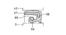
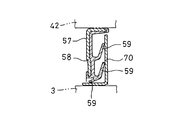
カバー部材42の内周と入力軸3の外周との間をシールするオイルシール57は、図12Aに示すように、シールリップ59を外径側から締め付けるガータースプリング69を有するものを採用してもよく、図12Bに示すように、シールリップ59が摺接するステンレススチール製のスリンガ70を有するものを採用してもよい。図12Bにおいて、スリンガ70は、入力軸3の外周に締め代をもって嵌合する断面L字状の部材である。
図13に、第2実施形態の回転伝達装置1を示す。第1実施形態に対応する部分は、同一の符号を付して説明を省略する。
アルミ製のカバー部材42の内周には、入力軸軸受53が嵌合する円筒状の軸受嵌合面71が形成されている。軸受嵌合面71の軸方向長さは、入力軸軸受53の軸方向幅よりも大きい。そのため、入力軸軸受53とフィールドコア40の間には軸方向隙間が形成され、入力軸軸受53がフィールドコア40と非接触となっている。
ここで、軸受嵌合面71は、カバー部材42に形成された円筒部72の内周に配置されている。円筒部72は、フィールドコア40から軸方向に延びる軸受嵌合筒52の内周に締め代をもって挿入されている。これにより、入力軸軸受53を高い剛性をもって支持しつつ、入力軸軸受53がフィールドコア40に接触するのを回避することが可能となっている。なお、円筒部72の軸方向端面は、フィールドコア40に突き当たっている。
この第2実施形態の回転伝達装置1は、入力軸軸受53が、非磁性材料であるアルミ製のカバー部材42の内周に電磁石30のフィールドコア40と非接触に配置されているので、電磁石30から生じる磁束が、入力軸軸受53を通って入力軸3に漏れるのが防止され、電磁石30によるアーマチュア31の吸引力を向上させることが可能である。
また、この回転伝達装置1は、軸受嵌合面71の軸方向長さが、入力軸軸受53の軸方向幅よりも大きいので、入力軸軸受53がフィールドコア40に接触するのを確実に防止することが可能である。
図14から図17に、この発明の実施形態の回転伝達装置1を用いた車両用操舵装置を示す。以下、上記各実施形態に対応する部分は同一の符号を付して説明を省略する。
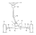
図14に示すように、この車両用操舵装置は、左右一対の転舵輪73に接続されるラック74と、ラック74を左右に移動可能に収容するラックハウジング75と、ラック74に噛み合うピニオン76(図15参照)と、ラックハウジング75に着脱可能に固定された回転伝達装置1と、運転者により操舵されるステアリングホイール77と、ステアリングホイール77の回転を回転伝達装置1に伝えるステアリングシャフト78とを有する。
ラック74の両端は、ボールジョイント79を介して左右の転舵輪73のナックルアーム80に接続されており、ラック74が左右に移動すると、その移動に応じてナックルアーム80が回動し、転舵輪73の向きが変化するようになっている。ラックハウジング75には、ラック74を左右に駆動する転舵用モータ81が取り付けられている。ここで、ラックハウジング75に対する転舵用モータ81の取り付け位置と、ラックハウジング75に対する回転伝達装置1の取り付け位置は互いに離れている。
ステアリングシャフト78のステアリングホイール77の側の端部には、ステアリングホイール77に操舵反力を付与する反力モータ82が取り付けられている。反力モータ82は、ステアリングホイール77の操舵角を検出する舵角センサを内蔵している。
図15に示すように、回転伝達装置1のケース2は、固定用フランジ48をラックハウジング75に形成された座面83に重ね合わせ、固定用フランジ48に形成された貫通孔49にボルト84を挿入し、そのボルト84を締め込むことで、ラックハウジング75に着脱可能に固定されている。ラックハウジング75は、ケース2の小径筒部2bの外周に形成した円筒面85と嵌合する円筒状の位置決め嵌合面86を有する。小径筒部2bの外周の円筒面85と位置決め嵌合面86との間は、Oリング87でシールされている。
図16に示すように、回転伝達装置1の入力軸3には、ダストカバー88が固定されている。ダストカバー88は、入力軸3のケース2からの突出部分の外周に締め代をもって嵌合する内筒部89と、内筒部89の一端から径方向外方に延びてケース2の大径筒部2aの開口端を覆うフランジ部90と、フランジ部90の外周から大径筒部2aの外周に沿って軸方向に延びる円筒状のスカート部91とを有する。スカート部91の内周と大径筒部2aの外周の間には、ラビリンス隙間が形成されている。ラビリンス隙間は、径方向の幅が1.0mm未満(好ましくは0.5mm以下)の微小隙間である。
ケース2の大径筒部2aには、電磁石30に電力を供給するリード線60が挿通する貫通孔61が形成されている。貫通孔61には、貫通孔61の内周とリード線60の外周との間をシールするゴム製のグロメット62が装着されている。グロメット62の構成は、上記実施形態と同様である。
図17に示すように、ピニオン76は、ラックハウジング75に組み付けられた第1ピニオン支持軸受92と第2ピニオン支持軸受93とで回転可能に支持されている。第1ピニオン支持軸受92は、図では、複列の深溝玉軸受を採用し、第2ピニオン支持軸受93は、図では針状ころ軸受を採用している。第1ピニオン支持軸受92および第2ピニオン支持軸受93は、ピニオン76のラック74に対する噛み合い部分を間に挟む両側でピニオン76を支持している。ここで、ピニオン76のラック74に対する噛み合い部分よりも回転伝達装置1に近い側でピニオン76を支持する軸受が第1ピニオン支持軸受92であり、ピニオン76のラック74に対する噛み合い部分よりも回転伝達装置1から遠い側でピニオン76を支持する軸受が第2ピニオン支持軸受93である。第1ピニオン支持軸受92は、回転伝達装置1のケース2の小径筒部2bとラックハウジング75との間で軸方向に挟んで固定されている。
出力軸4とピニオン76の相互間には、ケース2をラックハウジング75から取り外した状態では、回転伝達装置1の出力軸4がピニオン76から切り離され、ケース2をラックハウジング75に取り付けた状態では、出力軸4がピニオン76と一体に回転するように回り止め嵌合部94が設けられている。回り止め嵌合部94は、例えば、キーとキー溝を採用することも可能であるが、図のように、互いに嵌合するスプライン軸部とスプライン穴を採用すると、出力軸4とピニオン76の接続が容易となる。図では、出力軸4とピニオン76のうち、出力軸4の側にスプライン軸部を設け、ピニオン76の側にスプライン穴を設けているが、スプライン軸部とスプライン穴を逆にすることも可能である。
図14に示す実施形態の車両用操舵装置は、車両の通常走行時は、回転伝達装置1の電磁石30(図15参照)への通電状態を保つことで、回転伝達装置1を入力軸3から出力軸4への回転の伝達が遮断される空転状態として使用する。このとき、ステアリングホイール77の操舵角を、反力モータ82に内蔵した舵角センサで検知し、ステアリングホイール77の操舵角と転舵輪73の転舵角とが対応して変化するように、転舵用モータ81を作動させる。一方、電源が喪失したときなどの異常時は、回転伝達装置1の電磁石30(図15参照)への通電が停止するので、回転伝達装置1は、入力軸3から出力軸4に回転が伝達する締結状態となる。このとき、ステアリングホイール77の操作が、ステアリングシャフト78と回転伝達装置1とを順に介してピニオン76(図15参照)に機械的に伝達することで、転舵輪73の転舵角を変化させることが可能となる。
ところで、回転伝達装置1を自動車に組み付ける場合、従来は、図18に示すように、泥水などの異物が付着しにくい部位(ステアリングホイール77から車両操舵用のラック74に操舵力を伝えるステアリングシャフト78の中央位置)に組み付けて使用されることが多かった。図18において、ステアリングシャフト78には、ステアリングホイール77の側からラックハウジング75の側に向かって順に、反力モータ82、回転伝達装置1、転舵用モータ81が取り付けられている。
これに対し、図14に示す実施形態の車両用操舵装置においては、回転伝達装置1が、泥水などの異物が付着するおそれのある部位(具体的には、車両操舵用のラック74を収容するラックハウジング75。ラックハウジング75は、車両下側に露出した状態に組み付けられる)に直接取り付けられている。この場合、泥水などの異物が回転伝達装置1の内部に侵入するのを防ぐ必要がある。
この問題に対し、この実施形態の車両用操舵装置は、図15、図16に示すように、ケース2の大径筒部2aが上側、ケース2の小径筒部2bが下側となる向きで回転伝達装置1を取り付けたときに、ケース2の大径筒部2aの開口端に嵌め込まれたカバー部材42の上面がダストカバー88で覆われるので、カバー部材42の外周側の外側シール部材(Oリング55)や、カバー部材42の内周側の内側シール部材(オイルシール57)の近傍に、泥水などの異物が溜まるのを防止することができ、より効果的に回転伝達装置1の内部への異物侵入を防止することが可能となっている。
また、図16に示すように、回転伝達装置1のケース2の大径筒部2aの開口端の内周と入力軸3の外周との間が、カバー部材42とOリング55とオイルシール57とでシールされているので、泥水などの異物が付着するおそれのある環境で使用しても、その異物が回転伝達装置1の内部に侵入するのを防ぐことができる。
回転伝達装置1の出力軸4に直接ピニオン76を形成することも可能であるが、上記の車両用操舵装置は、ピニオン76と回転伝達装置1の出力軸4とが別体に形成されているので、ラックハウジング75とラック74とピニオン76とを組み立てる作業と、回転伝達装置1の構成部材を組み立てる作業とを別々に行なった後、ラックハウジング75に回転伝達装置1を組み付けることが可能であり、組み立て作業性に優れる。
また、この車両用操舵装置は、ラックハウジング75に、ケース2の小径筒部2bの外周に形成した円筒面85と嵌合する円筒状の位置決め嵌合面86が設けられているので、ラックハウジング75に回転伝達装置1を組み付けるときに、ピニオン76と出力軸4の芯ずれを防止することが容易である。
また、この車両用操舵装置は、小径筒部2bの外周の円筒面85と位置決め嵌合面86との間をシールするOリング87を有するので、回転伝達装置1をラックハウジング75に組み付けた後、泥水などの異物が回転伝達装置1のケース2の小径筒部2bとラックハウジング75との隙間を通ってラックハウジング75の内部に侵入するのを効果的に防止することが可能である。
また、この車両用操舵装置は、ピニオン76のラック74に対する噛み合い部分を間に挟む両側でピニオン76を支持するように第1ピニオン支持軸受92および第2ピニオン支持軸受93が設けられているので、ピニオン76の支持が安定し、ラック74に対するピニオン76の噛み合い精度が高い。
また、この車両用操舵装置は、第1ピニオン支持軸受92を、回転伝達装置1のケース2の小径筒部2bとラックハウジング75との間で軸方向に挟んで固定しているので、ピニオン支持軸受の軸方向のがたつきが防止され、ラック74に対するピニオン76の噛み合い精度を効果的に高めることが可能となっている。
上記実施形態では、外輪6の内周と内輪5の外周との間に組み込む係合子としてローラ7a,7bを採用した例を挙げて説明したが、この発明は、係合子としてボールやスプラグを採用した回転伝達装置1にも同様に適用することができる。
今回開示された実施の形態はすべての点で例示であって制限的なものではないと考えられるべきである。本発明の範囲は上記した説明ではなくて特許請求の範囲によって示され、特許請求の範囲と均等の意味および範囲内でのすべての変更が含まれることが意図される。
1 回転伝達装置
2 ケース
2a 大径筒部
2b 小径筒部
2c 連結部
3 入力軸
4 出力軸
5 内輪
6 外輪
7a,7b ローラ
8 ローラ保持器
30 電磁石
31 アーマチュア
33 ボールランプ機構
40 フィールドコア
41 ソレノイドコイル
42 カバー部材
53 入力軸軸受
55 Oリング
57 オイルシール
58 芯金
59 シールリップ
60 リード線
61 貫通孔
62 グロメット
63 出力軸軸受
66 出力軸シール部材
71 軸受嵌合面
73 転舵輪
74 ラック
75 ラックハウジング
76 ピニオン
85 円筒面
86 位置決め嵌合面
87 Oリング
88 ダストカバー
89 内筒部
90 フランジ部
91 スカート部
92 第1ピニオン支持軸受
93 第2ピニオン支持軸受
94 回り止め嵌合部
2 ケース
2a 大径筒部
2b 小径筒部
2c 連結部
3 入力軸
4 出力軸
5 内輪
6 外輪
7a,7b ローラ
8 ローラ保持器
30 電磁石
31 アーマチュア
33 ボールランプ機構
40 フィールドコア
41 ソレノイドコイル
42 カバー部材
53 入力軸軸受
55 Oリング
57 オイルシール
58 芯金
59 シールリップ
60 リード線
61 貫通孔
62 グロメット
63 出力軸軸受
66 出力軸シール部材
71 軸受嵌合面
73 転舵輪
74 ラック
75 ラックハウジング
76 ピニオン
85 円筒面
86 位置決め嵌合面
87 Oリング
88 ダストカバー
89 内筒部
90 フランジ部
91 スカート部
92 第1ピニオン支持軸受
93 第2ピニオン支持軸受
94 回り止め嵌合部
Claims (12)
- 円筒状の大径筒部(2a)と、前記大径筒部(2a)の内径よりも小さい内径をもつ円筒状の小径筒部(2b)と、前記大径筒部(2a)と前記小径筒部(2b)を連結する連結部(2c)とを継ぎ目の無い一体の部材としてもち、前記大径筒部(2a)の前記小径筒部(2b)側とは反対側の端部と前記小径筒部(2b)の前記大径筒部(2a)側とは反対側の端部とがそれぞれ開口した筒状のケース(2)と、
一端が前記ケース(2)内に収容され、他端が前記ケース(2)の前記大径筒部(2a)の開口端から突出した状態に設けられた入力軸(3)と、
前記入力軸(3)と同一直線上に配置され、一端が前記ケース(2)内に収容され、他端が前記ケース(2)の前記小径筒部(2b)の開口端から突出した状態に設けられた出力軸(4)と、
前記入力軸(3)と一体に回転するように前記入力軸(3)のケース(2)内への収容部分に設けられた内輪(5)と、
前記出力軸(4)と一体に回転するように前記出力軸(4)のケース(2)内への収容部分に接続して設けられ、前記内輪(5)を囲む環状に形成された外輪(6)と、
前記外輪(6)の内周と前記内輪(5)の外周との間に組み込まれた係合子(7a,7b)と、
前記係合子(7a,7b)を前記外輪(6)と前記内輪(5)の間に係合させる係合位置と、前記係合子(7a,7b)の係合を解除させる係合解除位置との間で移動可能に支持された係合子保持器(8)と、
前記大径筒部(2a)の内周と前記入力軸(3)の外周との間に組み込まれた環状の電磁石(30)と、
前記電磁石(30)の通電により軸方向に移動するように支持されたアーマチュア(31)と、
前記アーマチュア(31)の軸方向の移動を、前記係合子保持器(8)が前記係合位置と係合解除位置のうち一方から他方に移動する動作に変換する動作変換機構(33)と、
前記入力軸(3)を回転可能に支持する入力軸軸受(53)と、
前記出力軸(4)を回転可能に支持する出力軸軸受(63)と、
を有する回転伝達装置において、
前記出力軸(4)の外周と前記小径筒部(2b)の開口端の内周との間をシールする出力軸シール部材(66)と、
前記電磁石(30)と軸方向に対向するように前記大径筒部(2a)の開口端の内周に嵌め込まれたアルミ製の環板のカバー部材(42)と、
前記カバー部材(42)の外周と前記大径筒部(2a)の内周との間をシールする外側シール部材と、
前記カバー部材(42)の内周と前記入力軸(3)の外周との間をシールする内側シール部材とを有することを特徴とする回転伝達装置。 - 前記電磁石(30)は、前記大径筒部(2a)の内周に嵌合する環状に形成された磁性材料からなるフィールドコア(40)と、前記フィールドコア(40)に巻回されたソレノイドコイル(41)とを有し、
前記カバー部材(42)は、前記フィールドコア(40)に軸方向に突き当てて組み込まれ、
前記カバー部材(42)の内周に、前記入力軸軸受(53)が前記フィールドコア(40)と非接触となるように取り付けられている請求項1に記載の回転伝達装置。 - 前記カバー部材(42)の内周には、前記入力軸軸受(53)が嵌合する円筒状の軸受嵌合面(71)が形成され、
前記軸受嵌合面(71)の軸方向長さを、前記入力軸軸受(53)の軸方向幅よりも大きく設定することで、前記入力軸軸受(53)が前記フィールドコア(40)と非接触とされている請求項2に記載の回転伝達装置。 - 前記内側シール部材は、金属板からなる環状の芯金(58)と、前記芯金(58)に接着して設けられ、前記入力軸(3)の外周に摺接するゴム製のシールリップ(59)とを有するオイルシール(57)である請求項1から3のいずれかに記載の回転伝達装置。
- 前記外側シール部材は、ゴム製のOリング(55)である請求項1から4のいずれかに記載の回転伝達装置。
- 前記カバー部材(42)または前記大径筒部(2a)に、前記電磁石(30)に電力を供給するリード線(60)が挿通する貫通孔(61)が形成され、前記貫通孔(61)に、前記貫通孔(61)の内周と前記リード線(60)の外周との間をシールするゴム製のグロメット(62)を装着した請求項1から5のいずれかに記載の回転伝達装置。
- 前記入力軸(3)の前記ケース(2)からの突出部分の外周に締め代をもって嵌合する内筒部(89)と、前記内筒部(89)の一端から径方向外方に延びて前記ケース(2)の大径筒部(2a)の開口端を覆うフランジ部(90)と、前記フランジ部(90)の外周から前記大径筒部(2a)の外周に沿って軸方向に延びる円筒状のスカート部(91)とを有するダストカバー(88)を更に有する請求項1から6のいずれかに記載の回転伝達装置。
- 左右に移動可能に支持され、その移動に応じて左右一対の転舵輪(73)の向きが変化するように前記一対の転舵輪(73)に両端が接続されるラック(74)と、
前記ラック(74)を移動可能に収容するラックハウジング(75)と、
前記ラック(74)に噛み合うピニオン(76)と、
請求項1から7のいずれかに記載の回転伝達装置(1)と、を有し、
前記回転伝達装置(1)の前記ケース(2)は、前記ラックハウジング(75)に着脱可能に固定され、
前記ピニオン(76)は、前記ラックハウジング(75)に組み付けられたピニオン支持軸受(92,93)で回転可能に支持され、
前記ケース(2)を前記ラックハウジング(75)から取り外した状態では、前記回転伝達装置(1)の前記出力軸(4)が前記ピニオン(76)から切り離され、前記ケース(2)を前記ラックハウジング(75)に取り付けた状態では、前記出力軸(4)が前記ピニオン(76)と一体に回転するように、前記出力軸(4)と前記ピニオン(76)の相互間に回り止め嵌合部(94)が設けられている車両用操舵装置。 - 前記ラックハウジング(75)は、前記ケース(2)の前記小径筒部(2b)の外周に形成した円筒面(85)と嵌合する円筒状の位置決め嵌合面(86)を有する請求項8に記載の車両用操舵装置。
- 前記小径筒部(2b)の外周の前記円筒面(85)と前記位置決め嵌合面(86)との間をシールするOリング(87)を更に有する請求項9に記載の車両用操舵装置。
- 前記ピニオン支持軸受(92,93)は、前記ピニオン(76)の前記ラック(74)に対する噛み合い部分を間に挟む両側で前記ピニオン(76)を支持するように前記ラックハウジング(75)に複数設けられている請求項8から10のいずれかに記載の車両用操舵装置。
- 前記ピニオン(76)の前記ラック(74)に対する噛み合い部分を間に挟む両側に設けた複数の前記ピニオン支持軸受(92,93)のうち、前記ピニオン(76)の前記ラック(74)に対する噛み合い部分よりも前記回転伝達装置(1)に近い側のピニオン支持軸受(92)を、前記回転伝達装置(1)の前記ケース(2)の小径筒部(2b)と前記ラックハウジング(75)との間で軸方向に挟んで固定した請求項11に記載の車両用操舵装置。
Priority Applications (3)
| Application Number | Priority Date | Filing Date | Title |
|---|---|---|---|
| EP20840143.0A EP4001053B1 (en) | 2019-07-18 | 2020-07-15 | Rotation transmission device and steering device for a vehicle |
| US17/627,432 US11788585B2 (en) | 2019-07-18 | 2020-07-15 | Rotation transmission device and steering device for a vehicle |
| CN202080051294.4A CN114340976B (zh) | 2019-07-18 | 2020-07-15 | 旋转传递装置以及车辆用转向操纵装置 |
Applications Claiming Priority (2)
| Application Number | Priority Date | Filing Date | Title |
|---|---|---|---|
| JP2019-132762 | 2019-07-18 | ||
| JP2019132762A JP7389579B2 (ja) | 2019-07-18 | 2019-07-18 | 回転伝達装置および車両用操舵装置 |
Publications (1)
| Publication Number | Publication Date |
|---|---|
| WO2021010419A1 true WO2021010419A1 (ja) | 2021-01-21 |
Family
ID=74210911
Family Applications (1)
| Application Number | Title | Priority Date | Filing Date |
|---|---|---|---|
| PCT/JP2020/027498 Ceased WO2021010419A1 (ja) | 2019-07-18 | 2020-07-15 | 回転伝達装置および車両用操舵装置 |
Country Status (5)
| Country | Link |
|---|---|
| US (1) | US11788585B2 (ja) |
| EP (1) | EP4001053B1 (ja) |
| JP (1) | JP7389579B2 (ja) |
| CN (1) | CN114340976B (ja) |
| WO (1) | WO2021010419A1 (ja) |
Cited By (3)
| Publication number | Priority date | Publication date | Assignee | Title |
|---|---|---|---|---|
| CN113639041A (zh) * | 2021-07-16 | 2021-11-12 | 东风越野车有限公司 | 一种车用可拆卸管线过孔密封装置及其安装方法 |
| CN115163692A (zh) * | 2022-08-08 | 2022-10-11 | 中南大学 | 一种应用非等长楔块的缓接型斜撑离合器 |
| CN117141569A (zh) * | 2023-08-23 | 2023-12-01 | 一汽奔腾轿车有限公司 | 一种转向器及设计方法 |
Families Citing this family (7)
| Publication number | Priority date | Publication date | Assignee | Title |
|---|---|---|---|---|
| KR102672723B1 (ko) * | 2022-06-10 | 2024-06-07 | 에이치엘만도 주식회사 | 차량의 조향 시스템 |
| WO2022168850A1 (ja) * | 2021-02-04 | 2022-08-11 | 日本精工株式会社 | ステアリング装置 |
| WO2022168849A1 (ja) * | 2021-02-04 | 2022-08-11 | 日本精工株式会社 | ステアリング装置 |
| WO2023021707A1 (ja) * | 2021-08-20 | 2023-02-23 | 株式会社ジェイテクト | シール構造 |
| DE102022107288B3 (de) * | 2022-03-28 | 2023-03-09 | Schaeffler Technologies AG & Co. KG | Kupplungsanordnung mit radial verschiebbaren Steuerorganen sowie Antriebsstrang mit der Kupplungsanordnung |
| JP7726321B1 (ja) * | 2024-03-29 | 2025-08-20 | 株式会社富士通ゼネラル | 熱交換器および冷凍サイクル装置 |
| CN222988232U (zh) * | 2024-05-31 | 2025-06-17 | 比亚迪股份有限公司 | 离合装置、转向系统和车辆 |
Citations (4)
| Publication number | Priority date | Publication date | Assignee | Title |
|---|---|---|---|---|
| JP2002195300A (ja) * | 2000-12-27 | 2002-07-10 | Tochigi Fuji Ind Co Ltd | 電磁式カップリングのシール構造 |
| JP2014025483A (ja) | 2012-07-24 | 2014-02-06 | Ntn Corp | 回転伝達装置 |
| JP6491404B1 (ja) * | 2018-09-11 | 2019-03-27 | 株式会社ショーワ | クラッチ |
| WO2019135383A1 (ja) * | 2018-01-05 | 2019-07-11 | Ntn株式会社 | 回転伝達装置 |
Family Cites Families (11)
| Publication number | Priority date | Publication date | Assignee | Title |
|---|---|---|---|---|
| US6622837B2 (en) * | 2000-11-17 | 2003-09-23 | The Hilliard Corporation | Bi-directional overrunning clutch with automatic backdrive |
| JP2007064465A (ja) * | 2005-09-02 | 2007-03-15 | Ntn Corp | 回転伝達装置 |
| JP2012153247A (ja) * | 2011-01-26 | 2012-08-16 | Toyota Motor Corp | カップリング装置 |
| EP2833014B1 (en) | 2012-03-26 | 2018-07-18 | NTN Corporation | Rotation transmission device |
| EP2835550B1 (en) | 2012-04-02 | 2019-05-08 | NTN Corporation | Rotation transmission device |
| KR20150017627A (ko) * | 2013-08-07 | 2015-02-17 | 주식회사 만도 | 자동차의 조향장치 |
| JP6494171B2 (ja) * | 2014-03-27 | 2019-04-03 | Ntn株式会社 | 回転伝達装置 |
| JP2015189346A (ja) | 2014-03-28 | 2015-11-02 | Ntn株式会社 | 車両操舵システム用ユニット |
| JP6486089B2 (ja) | 2014-12-09 | 2019-03-20 | Ntn株式会社 | 回転伝達装置 |
| JP6970537B2 (ja) * | 2017-06-30 | 2021-11-24 | Ntn株式会社 | 回転伝達装置 |
| JP6922716B2 (ja) * | 2017-12-15 | 2021-08-18 | 株式会社ジェイテクト | ステアリング装置 |
-
2019
- 2019-07-18 JP JP2019132762A patent/JP7389579B2/ja active Active
-
2020
- 2020-07-15 CN CN202080051294.4A patent/CN114340976B/zh active Active
- 2020-07-15 US US17/627,432 patent/US11788585B2/en active Active
- 2020-07-15 EP EP20840143.0A patent/EP4001053B1/en active Active
- 2020-07-15 WO PCT/JP2020/027498 patent/WO2021010419A1/ja not_active Ceased
Patent Citations (4)
| Publication number | Priority date | Publication date | Assignee | Title |
|---|---|---|---|---|
| JP2002195300A (ja) * | 2000-12-27 | 2002-07-10 | Tochigi Fuji Ind Co Ltd | 電磁式カップリングのシール構造 |
| JP2014025483A (ja) | 2012-07-24 | 2014-02-06 | Ntn Corp | 回転伝達装置 |
| WO2019135383A1 (ja) * | 2018-01-05 | 2019-07-11 | Ntn株式会社 | 回転伝達装置 |
| JP6491404B1 (ja) * | 2018-09-11 | 2019-03-27 | 株式会社ショーワ | クラッチ |
Cited By (5)
| Publication number | Priority date | Publication date | Assignee | Title |
|---|---|---|---|---|
| CN113639041A (zh) * | 2021-07-16 | 2021-11-12 | 东风越野车有限公司 | 一种车用可拆卸管线过孔密封装置及其安装方法 |
| CN113639041B (zh) * | 2021-07-16 | 2023-06-09 | 东风越野车有限公司 | 一种车用可拆卸管线过孔密封装置及其安装方法 |
| CN115163692A (zh) * | 2022-08-08 | 2022-10-11 | 中南大学 | 一种应用非等长楔块的缓接型斜撑离合器 |
| CN115163692B (zh) * | 2022-08-08 | 2023-09-26 | 中南大学 | 一种应用非等长楔块的缓接型斜撑离合器 |
| CN117141569A (zh) * | 2023-08-23 | 2023-12-01 | 一汽奔腾轿车有限公司 | 一种转向器及设计方法 |
Also Published As
| Publication number | Publication date |
|---|---|
| JP7389579B2 (ja) | 2023-11-30 |
| EP4001053A4 (en) | 2022-08-31 |
| CN114340976B (zh) | 2024-09-17 |
| EP4001053A1 (en) | 2022-05-25 |
| US11788585B2 (en) | 2023-10-17 |
| CN114340976A (zh) | 2022-04-12 |
| JP2021017908A (ja) | 2021-02-15 |
| US20220260121A1 (en) | 2022-08-18 |
| EP4001053B1 (en) | 2025-05-21 |
Similar Documents
| Publication | Publication Date | Title |
|---|---|---|
| JP7389579B2 (ja) | 回転伝達装置および車両用操舵装置 | |
| CN106164523B (zh) | 旋转传递装置 | |
| WO2013150982A1 (ja) | 回転伝達装置 | |
| JP6970537B2 (ja) | 回転伝達装置 | |
| CN103649595A (zh) | 带单向离合器内置型皮带轮的旋转机械装置 | |
| CN111886420A (zh) | 旋转传递装置 | |
| JP2023043475A (ja) | 電動アクチュエータ | |
| JPH11182543A (ja) | 複列転がり軸受ユニットとその製造方法 | |
| JP2002195280A (ja) | 車軸用軸受装置 | |
| JP4530666B2 (ja) | スラスト軸受組立体 | |
| JP3688973B2 (ja) | 回転伝達装置 | |
| JP4894652B2 (ja) | 車輪支持用転がり軸受ユニットの製造方法 | |
| JP2006132709A (ja) | センサ付転がり軸受 | |
| JP2006224910A (ja) | 回転伝達装置 | |
| JP2017125571A (ja) | 回転伝達装置 | |
| JP6013063B2 (ja) | 回転伝達装置 | |
| JP7639593B2 (ja) | 回転動力伝達機構 | |
| JP2003166626A (ja) | ピニオン軸支持用軸受装置 | |
| JP2023043476A (ja) | 電動アクチュエータ | |
| JP2008075832A (ja) | 転がり軸受装置 | |
| JP2021001674A (ja) | 回転伝達装置、および回転伝達装置の製造方法 | |
| JP2020159430A (ja) | 回転伝達装置及び車両用ステアバイワイヤ操舵装置 | |
| JP6732488B2 (ja) | 回転伝達装置 | |
| JP6468773B2 (ja) | 回転伝達装置 | |
| WO2020262191A1 (ja) | 回転伝達装置、および回転伝達装置の製造方法 |
Legal Events
| Date | Code | Title | Description |
|---|---|---|---|
| 121 | Ep: the epo has been informed by wipo that ep was designated in this application |
Ref document number: 20840143 Country of ref document: EP Kind code of ref document: A1 |
|
| NENP | Non-entry into the national phase |
Ref country code: DE |
|
| ENP | Entry into the national phase |
Ref document number: 2020840143 Country of ref document: EP Effective date: 20220218 |
|
| WWG | Wipo information: grant in national office |
Ref document number: 2020840143 Country of ref document: EP |