WO2021010477A1 - 立方晶窒化硼素焼結体 - Google Patents
立方晶窒化硼素焼結体 Download PDFInfo
- Publication number
- WO2021010477A1 WO2021010477A1 PCT/JP2020/027904 JP2020027904W WO2021010477A1 WO 2021010477 A1 WO2021010477 A1 WO 2021010477A1 JP 2020027904 W JP2020027904 W JP 2020027904W WO 2021010477 A1 WO2021010477 A1 WO 2021010477A1
- Authority
- WO
- WIPO (PCT)
- Prior art keywords
- powder
- binder
- sintered body
- particles
- cbn
- Prior art date
- Legal status (The legal status is an assumption and is not a legal conclusion. Google has not performed a legal analysis and makes no representation as to the accuracy of the status listed.)
- Ceased
Links
Images


Classifications
-
- C—CHEMISTRY; METALLURGY
- C04—CEMENTS; CONCRETE; ARTIFICIAL STONE; CERAMICS; REFRACTORIES
- C04B—LIME, MAGNESIA; SLAG; CEMENTS; COMPOSITIONS THEREOF, e.g. MORTARS, CONCRETE OR LIKE BUILDING MATERIALS; ARTIFICIAL STONE; CERAMICS; REFRACTORIES; TREATMENT OF NATURAL STONE
- C04B35/00—Shaped ceramic products characterised by their composition; Ceramics compositions; Processing powders of inorganic compounds preparatory to the manufacturing of ceramic products
- C04B35/515—Shaped ceramic products characterised by their composition; Ceramics compositions; Processing powders of inorganic compounds preparatory to the manufacturing of ceramic products based on non-oxide ceramics
- C04B35/58—Shaped ceramic products characterised by their composition; Ceramics compositions; Processing powders of inorganic compounds preparatory to the manufacturing of ceramic products based on non-oxide ceramics based on borides, nitrides, i.e. nitrides, oxynitrides, carbonitrides or oxycarbonitrides or silicides
- C04B35/583—Shaped ceramic products characterised by their composition; Ceramics compositions; Processing powders of inorganic compounds preparatory to the manufacturing of ceramic products based on non-oxide ceramics based on borides, nitrides, i.e. nitrides, oxynitrides, carbonitrides or oxycarbonitrides or silicides based on boron nitride
- C04B35/5831—Shaped ceramic products characterised by their composition; Ceramics compositions; Processing powders of inorganic compounds preparatory to the manufacturing of ceramic products based on non-oxide ceramics based on borides, nitrides, i.e. nitrides, oxynitrides, carbonitrides or oxycarbonitrides or silicides based on boron nitride based on cubic boron nitrides or Wurtzitic boron nitrides, including crystal structure transformation of powder
-
- C—CHEMISTRY; METALLURGY
- C04—CEMENTS; CONCRETE; ARTIFICIAL STONE; CERAMICS; REFRACTORIES
- C04B—LIME, MAGNESIA; SLAG; CEMENTS; COMPOSITIONS THEREOF, e.g. MORTARS, CONCRETE OR LIKE BUILDING MATERIALS; ARTIFICIAL STONE; CERAMICS; REFRACTORIES; TREATMENT OF NATURAL STONE
- C04B35/00—Shaped ceramic products characterised by their composition; Ceramics compositions; Processing powders of inorganic compounds preparatory to the manufacturing of ceramic products
- C04B35/622—Forming processes; Processing powders of inorganic compounds preparatory to the manufacturing of ceramic products
-
- C—CHEMISTRY; METALLURGY
- C04—CEMENTS; CONCRETE; ARTIFICIAL STONE; CERAMICS; REFRACTORIES
- C04B—LIME, MAGNESIA; SLAG; CEMENTS; COMPOSITIONS THEREOF, e.g. MORTARS, CONCRETE OR LIKE BUILDING MATERIALS; ARTIFICIAL STONE; CERAMICS; REFRACTORIES; TREATMENT OF NATURAL STONE
- C04B35/00—Shaped ceramic products characterised by their composition; Ceramics compositions; Processing powders of inorganic compounds preparatory to the manufacturing of ceramic products
- C04B35/622—Forming processes; Processing powders of inorganic compounds preparatory to the manufacturing of ceramic products
- C04B35/626—Preparing or treating the powders individually or as batches ; preparing or treating macroscopic reinforcing agents for ceramic products, e.g. fibres; mechanical aspects section B
- C04B35/62605—Treating the starting powders individually or as mixtures
- C04B35/6261—Milling
- C04B35/6262—Milling of calcined, sintered clinker or ceramics
-
- C—CHEMISTRY; METALLURGY
- C04—CEMENTS; CONCRETE; ARTIFICIAL STONE; CERAMICS; REFRACTORIES
- C04B—LIME, MAGNESIA; SLAG; CEMENTS; COMPOSITIONS THEREOF, e.g. MORTARS, CONCRETE OR LIKE BUILDING MATERIALS; ARTIFICIAL STONE; CERAMICS; REFRACTORIES; TREATMENT OF NATURAL STONE
- C04B35/00—Shaped ceramic products characterised by their composition; Ceramics compositions; Processing powders of inorganic compounds preparatory to the manufacturing of ceramic products
- C04B35/622—Forming processes; Processing powders of inorganic compounds preparatory to the manufacturing of ceramic products
- C04B35/626—Preparing or treating the powders individually or as batches ; preparing or treating macroscopic reinforcing agents for ceramic products, e.g. fibres; mechanical aspects section B
- C04B35/62605—Treating the starting powders individually or as mixtures
- C04B35/62645—Thermal treatment of powders or mixtures thereof other than sintering
- C04B35/62665—Flame, plasma or melting treatment
-
- C—CHEMISTRY; METALLURGY
- C04—CEMENTS; CONCRETE; ARTIFICIAL STONE; CERAMICS; REFRACTORIES
- C04B—LIME, MAGNESIA; SLAG; CEMENTS; COMPOSITIONS THEREOF, e.g. MORTARS, CONCRETE OR LIKE BUILDING MATERIALS; ARTIFICIAL STONE; CERAMICS; REFRACTORIES; TREATMENT OF NATURAL STONE
- C04B35/00—Shaped ceramic products characterised by their composition; Ceramics compositions; Processing powders of inorganic compounds preparatory to the manufacturing of ceramic products
- C04B35/622—Forming processes; Processing powders of inorganic compounds preparatory to the manufacturing of ceramic products
- C04B35/64—Burning or sintering processes
- C04B35/645—Pressure sintering
-
- C—CHEMISTRY; METALLURGY
- C22—METALLURGY; FERROUS OR NON-FERROUS ALLOYS; TREATMENT OF ALLOYS OR NON-FERROUS METALS
- C22C—ALLOYS
- C22C26/00—Alloys containing diamond or cubic or wurtzitic boron nitride, fullerenes or carbon nanotubes
-
- B—PERFORMING OPERATIONS; TRANSPORTING
- B22—CASTING; POWDER METALLURGY
- B22F—WORKING METALLIC POWDER; MANUFACTURE OF ARTICLES FROM METALLIC POWDER; MAKING METALLIC POWDER; APPARATUS OR DEVICES SPECIALLY ADAPTED FOR METALLIC POWDER
- B22F5/00—Manufacture of workpieces or articles from metallic powder characterised by the special shape of the product
- B22F2005/001—Cutting tools, earth boring or grinding tool other than table ware
-
- B—PERFORMING OPERATIONS; TRANSPORTING
- B22—CASTING; POWDER METALLURGY
- B22F—WORKING METALLIC POWDER; MANUFACTURE OF ARTICLES FROM METALLIC POWDER; MAKING METALLIC POWDER; APPARATUS OR DEVICES SPECIALLY ADAPTED FOR METALLIC POWDER
- B22F2998/00—Supplementary information concerning processes or compositions relating to powder metallurgy
- B22F2998/10—Processes characterised by the sequence of their steps
-
- C—CHEMISTRY; METALLURGY
- C04—CEMENTS; CONCRETE; ARTIFICIAL STONE; CERAMICS; REFRACTORIES
- C04B—LIME, MAGNESIA; SLAG; CEMENTS; COMPOSITIONS THEREOF, e.g. MORTARS, CONCRETE OR LIKE BUILDING MATERIALS; ARTIFICIAL STONE; CERAMICS; REFRACTORIES; TREATMENT OF NATURAL STONE
- C04B2235/00—Aspects relating to ceramic starting mixtures or sintered ceramic products
- C04B2235/02—Composition of constituents of the starting material or of secondary phases of the final product
- C04B2235/30—Constituents and secondary phases not being of a fibrous nature
- C04B2235/32—Metal oxides, mixed metal oxides, or oxide-forming salts thereof, e.g. carbonates, nitrates, (oxy)hydroxides, chlorides
- C04B2235/3217—Aluminum oxide or oxide forming salts thereof, e.g. bauxite, alpha-alumina
-
- C—CHEMISTRY; METALLURGY
- C04—CEMENTS; CONCRETE; ARTIFICIAL STONE; CERAMICS; REFRACTORIES
- C04B—LIME, MAGNESIA; SLAG; CEMENTS; COMPOSITIONS THEREOF, e.g. MORTARS, CONCRETE OR LIKE BUILDING MATERIALS; ARTIFICIAL STONE; CERAMICS; REFRACTORIES; TREATMENT OF NATURAL STONE
- C04B2235/00—Aspects relating to ceramic starting mixtures or sintered ceramic products
- C04B2235/02—Composition of constituents of the starting material or of secondary phases of the final product
- C04B2235/30—Constituents and secondary phases not being of a fibrous nature
- C04B2235/32—Metal oxides, mixed metal oxides, or oxide-forming salts thereof, e.g. carbonates, nitrates, (oxy)hydroxides, chlorides
- C04B2235/3231—Refractory metal oxides, their mixed metal oxides, or oxide-forming salts thereof
- C04B2235/3232—Titanium oxides or titanates, e.g. rutile or anatase
-
- C—CHEMISTRY; METALLURGY
- C04—CEMENTS; CONCRETE; ARTIFICIAL STONE; CERAMICS; REFRACTORIES
- C04B—LIME, MAGNESIA; SLAG; CEMENTS; COMPOSITIONS THEREOF, e.g. MORTARS, CONCRETE OR LIKE BUILDING MATERIALS; ARTIFICIAL STONE; CERAMICS; REFRACTORIES; TREATMENT OF NATURAL STONE
- C04B2235/00—Aspects relating to ceramic starting mixtures or sintered ceramic products
- C04B2235/02—Composition of constituents of the starting material or of secondary phases of the final product
- C04B2235/30—Constituents and secondary phases not being of a fibrous nature
- C04B2235/32—Metal oxides, mixed metal oxides, or oxide-forming salts thereof, e.g. carbonates, nitrates, (oxy)hydroxides, chlorides
- C04B2235/3231—Refractory metal oxides, their mixed metal oxides, or oxide-forming salts thereof
- C04B2235/3239—Vanadium oxides, vanadates or oxide forming salts thereof, e.g. magnesium vanadate
-
- C—CHEMISTRY; METALLURGY
- C04—CEMENTS; CONCRETE; ARTIFICIAL STONE; CERAMICS; REFRACTORIES
- C04B—LIME, MAGNESIA; SLAG; CEMENTS; COMPOSITIONS THEREOF, e.g. MORTARS, CONCRETE OR LIKE BUILDING MATERIALS; ARTIFICIAL STONE; CERAMICS; REFRACTORIES; TREATMENT OF NATURAL STONE
- C04B2235/00—Aspects relating to ceramic starting mixtures or sintered ceramic products
- C04B2235/02—Composition of constituents of the starting material or of secondary phases of the final product
- C04B2235/30—Constituents and secondary phases not being of a fibrous nature
- C04B2235/32—Metal oxides, mixed metal oxides, or oxide-forming salts thereof, e.g. carbonates, nitrates, (oxy)hydroxides, chlorides
- C04B2235/3231—Refractory metal oxides, their mixed metal oxides, or oxide-forming salts thereof
- C04B2235/3241—Chromium oxides, chromates, or oxide-forming salts thereof
-
- C—CHEMISTRY; METALLURGY
- C04—CEMENTS; CONCRETE; ARTIFICIAL STONE; CERAMICS; REFRACTORIES
- C04B—LIME, MAGNESIA; SLAG; CEMENTS; COMPOSITIONS THEREOF, e.g. MORTARS, CONCRETE OR LIKE BUILDING MATERIALS; ARTIFICIAL STONE; CERAMICS; REFRACTORIES; TREATMENT OF NATURAL STONE
- C04B2235/00—Aspects relating to ceramic starting mixtures or sintered ceramic products
- C04B2235/02—Composition of constituents of the starting material or of secondary phases of the final product
- C04B2235/30—Constituents and secondary phases not being of a fibrous nature
- C04B2235/32—Metal oxides, mixed metal oxides, or oxide-forming salts thereof, e.g. carbonates, nitrates, (oxy)hydroxides, chlorides
- C04B2235/3231—Refractory metal oxides, their mixed metal oxides, or oxide-forming salts thereof
- C04B2235/3244—Zirconium oxides, zirconates, hafnium oxides, hafnates, or oxide-forming salts thereof
-
- C—CHEMISTRY; METALLURGY
- C04—CEMENTS; CONCRETE; ARTIFICIAL STONE; CERAMICS; REFRACTORIES
- C04B—LIME, MAGNESIA; SLAG; CEMENTS; COMPOSITIONS THEREOF, e.g. MORTARS, CONCRETE OR LIKE BUILDING MATERIALS; ARTIFICIAL STONE; CERAMICS; REFRACTORIES; TREATMENT OF NATURAL STONE
- C04B2235/00—Aspects relating to ceramic starting mixtures or sintered ceramic products
- C04B2235/02—Composition of constituents of the starting material or of secondary phases of the final product
- C04B2235/30—Constituents and secondary phases not being of a fibrous nature
- C04B2235/32—Metal oxides, mixed metal oxides, or oxide-forming salts thereof, e.g. carbonates, nitrates, (oxy)hydroxides, chlorides
- C04B2235/3231—Refractory metal oxides, their mixed metal oxides, or oxide-forming salts thereof
- C04B2235/3251—Niobium oxides, niobates, tantalum oxides, tantalates, or oxide-forming salts thereof
-
- C—CHEMISTRY; METALLURGY
- C04—CEMENTS; CONCRETE; ARTIFICIAL STONE; CERAMICS; REFRACTORIES
- C04B—LIME, MAGNESIA; SLAG; CEMENTS; COMPOSITIONS THEREOF, e.g. MORTARS, CONCRETE OR LIKE BUILDING MATERIALS; ARTIFICIAL STONE; CERAMICS; REFRACTORIES; TREATMENT OF NATURAL STONE
- C04B2235/00—Aspects relating to ceramic starting mixtures or sintered ceramic products
- C04B2235/02—Composition of constituents of the starting material or of secondary phases of the final product
- C04B2235/30—Constituents and secondary phases not being of a fibrous nature
- C04B2235/32—Metal oxides, mixed metal oxides, or oxide-forming salts thereof, e.g. carbonates, nitrates, (oxy)hydroxides, chlorides
- C04B2235/3231—Refractory metal oxides, their mixed metal oxides, or oxide-forming salts thereof
- C04B2235/3256—Molybdenum oxides, molybdates or oxide forming salts thereof, e.g. cadmium molybdate
-
- C—CHEMISTRY; METALLURGY
- C04—CEMENTS; CONCRETE; ARTIFICIAL STONE; CERAMICS; REFRACTORIES
- C04B—LIME, MAGNESIA; SLAG; CEMENTS; COMPOSITIONS THEREOF, e.g. MORTARS, CONCRETE OR LIKE BUILDING MATERIALS; ARTIFICIAL STONE; CERAMICS; REFRACTORIES; TREATMENT OF NATURAL STONE
- C04B2235/00—Aspects relating to ceramic starting mixtures or sintered ceramic products
- C04B2235/02—Composition of constituents of the starting material or of secondary phases of the final product
- C04B2235/30—Constituents and secondary phases not being of a fibrous nature
- C04B2235/32—Metal oxides, mixed metal oxides, or oxide-forming salts thereof, e.g. carbonates, nitrates, (oxy)hydroxides, chlorides
- C04B2235/3231—Refractory metal oxides, their mixed metal oxides, or oxide-forming salts thereof
- C04B2235/3258—Tungsten oxides, tungstates, or oxide-forming salts thereof
-
- C—CHEMISTRY; METALLURGY
- C04—CEMENTS; CONCRETE; ARTIFICIAL STONE; CERAMICS; REFRACTORIES
- C04B—LIME, MAGNESIA; SLAG; CEMENTS; COMPOSITIONS THEREOF, e.g. MORTARS, CONCRETE OR LIKE BUILDING MATERIALS; ARTIFICIAL STONE; CERAMICS; REFRACTORIES; TREATMENT OF NATURAL STONE
- C04B2235/00—Aspects relating to ceramic starting mixtures or sintered ceramic products
- C04B2235/02—Composition of constituents of the starting material or of secondary phases of the final product
- C04B2235/30—Constituents and secondary phases not being of a fibrous nature
- C04B2235/38—Non-oxide ceramic constituents or additives
- C04B2235/3804—Borides
- C04B2235/3813—Refractory metal borides
-
- C—CHEMISTRY; METALLURGY
- C04—CEMENTS; CONCRETE; ARTIFICIAL STONE; CERAMICS; REFRACTORIES
- C04B—LIME, MAGNESIA; SLAG; CEMENTS; COMPOSITIONS THEREOF, e.g. MORTARS, CONCRETE OR LIKE BUILDING MATERIALS; ARTIFICIAL STONE; CERAMICS; REFRACTORIES; TREATMENT OF NATURAL STONE
- C04B2235/00—Aspects relating to ceramic starting mixtures or sintered ceramic products
- C04B2235/02—Composition of constituents of the starting material or of secondary phases of the final product
- C04B2235/30—Constituents and secondary phases not being of a fibrous nature
- C04B2235/38—Non-oxide ceramic constituents or additives
- C04B2235/3817—Carbides
-
- C—CHEMISTRY; METALLURGY
- C04—CEMENTS; CONCRETE; ARTIFICIAL STONE; CERAMICS; REFRACTORIES
- C04B—LIME, MAGNESIA; SLAG; CEMENTS; COMPOSITIONS THEREOF, e.g. MORTARS, CONCRETE OR LIKE BUILDING MATERIALS; ARTIFICIAL STONE; CERAMICS; REFRACTORIES; TREATMENT OF NATURAL STONE
- C04B2235/00—Aspects relating to ceramic starting mixtures or sintered ceramic products
- C04B2235/02—Composition of constituents of the starting material or of secondary phases of the final product
- C04B2235/30—Constituents and secondary phases not being of a fibrous nature
- C04B2235/38—Non-oxide ceramic constituents or additives
- C04B2235/3817—Carbides
- C04B2235/3839—Refractory metal carbides
-
- C—CHEMISTRY; METALLURGY
- C04—CEMENTS; CONCRETE; ARTIFICIAL STONE; CERAMICS; REFRACTORIES
- C04B—LIME, MAGNESIA; SLAG; CEMENTS; COMPOSITIONS THEREOF, e.g. MORTARS, CONCRETE OR LIKE BUILDING MATERIALS; ARTIFICIAL STONE; CERAMICS; REFRACTORIES; TREATMENT OF NATURAL STONE
- C04B2235/00—Aspects relating to ceramic starting mixtures or sintered ceramic products
- C04B2235/02—Composition of constituents of the starting material or of secondary phases of the final product
- C04B2235/30—Constituents and secondary phases not being of a fibrous nature
- C04B2235/38—Non-oxide ceramic constituents or additives
- C04B2235/3852—Nitrides, e.g. oxynitrides, carbonitrides, oxycarbonitrides, lithium nitride, magnesium nitride
- C04B2235/3856—Carbonitrides, e.g. titanium carbonitride, zirconium carbonitride
-
- C—CHEMISTRY; METALLURGY
- C04—CEMENTS; CONCRETE; ARTIFICIAL STONE; CERAMICS; REFRACTORIES
- C04B—LIME, MAGNESIA; SLAG; CEMENTS; COMPOSITIONS THEREOF, e.g. MORTARS, CONCRETE OR LIKE BUILDING MATERIALS; ARTIFICIAL STONE; CERAMICS; REFRACTORIES; TREATMENT OF NATURAL STONE
- C04B2235/00—Aspects relating to ceramic starting mixtures or sintered ceramic products
- C04B2235/02—Composition of constituents of the starting material or of secondary phases of the final product
- C04B2235/30—Constituents and secondary phases not being of a fibrous nature
- C04B2235/38—Non-oxide ceramic constituents or additives
- C04B2235/3852—Nitrides, e.g. oxynitrides, carbonitrides, oxycarbonitrides, lithium nitride, magnesium nitride
- C04B2235/386—Boron nitrides
-
- C—CHEMISTRY; METALLURGY
- C04—CEMENTS; CONCRETE; ARTIFICIAL STONE; CERAMICS; REFRACTORIES
- C04B—LIME, MAGNESIA; SLAG; CEMENTS; COMPOSITIONS THEREOF, e.g. MORTARS, CONCRETE OR LIKE BUILDING MATERIALS; ARTIFICIAL STONE; CERAMICS; REFRACTORIES; TREATMENT OF NATURAL STONE
- C04B2235/00—Aspects relating to ceramic starting mixtures or sintered ceramic products
- C04B2235/02—Composition of constituents of the starting material or of secondary phases of the final product
- C04B2235/30—Constituents and secondary phases not being of a fibrous nature
- C04B2235/38—Non-oxide ceramic constituents or additives
- C04B2235/3852—Nitrides, e.g. oxynitrides, carbonitrides, oxycarbonitrides, lithium nitride, magnesium nitride
- C04B2235/3865—Aluminium nitrides
-
- C—CHEMISTRY; METALLURGY
- C04—CEMENTS; CONCRETE; ARTIFICIAL STONE; CERAMICS; REFRACTORIES
- C04B—LIME, MAGNESIA; SLAG; CEMENTS; COMPOSITIONS THEREOF, e.g. MORTARS, CONCRETE OR LIKE BUILDING MATERIALS; ARTIFICIAL STONE; CERAMICS; REFRACTORIES; TREATMENT OF NATURAL STONE
- C04B2235/00—Aspects relating to ceramic starting mixtures or sintered ceramic products
- C04B2235/02—Composition of constituents of the starting material or of secondary phases of the final product
- C04B2235/30—Constituents and secondary phases not being of a fibrous nature
- C04B2235/38—Non-oxide ceramic constituents or additives
- C04B2235/3852—Nitrides, e.g. oxynitrides, carbonitrides, oxycarbonitrides, lithium nitride, magnesium nitride
- C04B2235/3886—Refractory metal nitrides, e.g. vanadium nitride, tungsten nitride
-
- C—CHEMISTRY; METALLURGY
- C04—CEMENTS; CONCRETE; ARTIFICIAL STONE; CERAMICS; REFRACTORIES
- C04B—LIME, MAGNESIA; SLAG; CEMENTS; COMPOSITIONS THEREOF, e.g. MORTARS, CONCRETE OR LIKE BUILDING MATERIALS; ARTIFICIAL STONE; CERAMICS; REFRACTORIES; TREATMENT OF NATURAL STONE
- C04B2235/00—Aspects relating to ceramic starting mixtures or sintered ceramic products
- C04B2235/02—Composition of constituents of the starting material or of secondary phases of the final product
- C04B2235/50—Constituents or additives of the starting mixture chosen for their shape or used because of their shape or their physical appearance
- C04B2235/54—Particle size related information
- C04B2235/5418—Particle size related information expressed by the size of the particles or aggregates thereof
- C04B2235/5445—Particle size related information expressed by the size of the particles or aggregates thereof submicron sized, i.e. from 0,1 to 1 micron
-
- C—CHEMISTRY; METALLURGY
- C04—CEMENTS; CONCRETE; ARTIFICIAL STONE; CERAMICS; REFRACTORIES
- C04B—LIME, MAGNESIA; SLAG; CEMENTS; COMPOSITIONS THEREOF, e.g. MORTARS, CONCRETE OR LIKE BUILDING MATERIALS; ARTIFICIAL STONE; CERAMICS; REFRACTORIES; TREATMENT OF NATURAL STONE
- C04B2235/00—Aspects relating to ceramic starting mixtures or sintered ceramic products
- C04B2235/65—Aspects relating to heat treatments of ceramic bodies such as green ceramics or pre-sintered ceramics, e.g. burning, sintering or melting processes
- C04B2235/656—Aspects relating to heat treatments of ceramic bodies such as green ceramics or pre-sintered ceramics, e.g. burning, sintering or melting processes characterised by specific heating conditions during heat treatment
- C04B2235/6567—Treatment time
-
- C—CHEMISTRY; METALLURGY
- C04—CEMENTS; CONCRETE; ARTIFICIAL STONE; CERAMICS; REFRACTORIES
- C04B—LIME, MAGNESIA; SLAG; CEMENTS; COMPOSITIONS THEREOF, e.g. MORTARS, CONCRETE OR LIKE BUILDING MATERIALS; ARTIFICIAL STONE; CERAMICS; REFRACTORIES; TREATMENT OF NATURAL STONE
- C04B2235/00—Aspects relating to ceramic starting mixtures or sintered ceramic products
- C04B2235/70—Aspects relating to sintered or melt-casted ceramic products
- C04B2235/74—Physical characteristics
- C04B2235/78—Grain sizes and shapes, product microstructures, e.g. acicular grains, equiaxed grains, platelet-structures
- C04B2235/785—Submicron sized grains, i.e. from 0,1 to 1 micron
-
- C—CHEMISTRY; METALLURGY
- C04—CEMENTS; CONCRETE; ARTIFICIAL STONE; CERAMICS; REFRACTORIES
- C04B—LIME, MAGNESIA; SLAG; CEMENTS; COMPOSITIONS THEREOF, e.g. MORTARS, CONCRETE OR LIKE BUILDING MATERIALS; ARTIFICIAL STONE; CERAMICS; REFRACTORIES; TREATMENT OF NATURAL STONE
- C04B2235/00—Aspects relating to ceramic starting mixtures or sintered ceramic products
- C04B2235/70—Aspects relating to sintered or melt-casted ceramic products
- C04B2235/80—Phases present in the sintered or melt-cast ceramic products other than the main phase
-
- C—CHEMISTRY; METALLURGY
- C22—METALLURGY; FERROUS OR NON-FERROUS ALLOYS; TREATMENT OF ALLOYS OR NON-FERROUS METALS
- C22C—ALLOYS
- C22C26/00—Alloys containing diamond or cubic or wurtzitic boron nitride, fullerenes or carbon nanotubes
- C22C2026/003—Cubic boron nitrides only
Definitions
- the present disclosure relates to a cubic boron nitride sintered body.
- This application claims priority based on Japanese Patent Application No. 2019-133028, which is a Japanese patent application filed on July 18, 2019. All the contents of the Japanese patent application are incorporated herein by reference.
- cBN sintered body As a high-hardness material used for cutting tools and the like, there is a cubic boron nitride sintered body (hereinafter, also referred to as “cBN sintered body”).
- the cBN sintered body is usually composed of cubic boron nitride particles (hereinafter, also referred to as “cBN particles”) and a bonded phase, and its characteristics tend to differ depending on the content ratio of the cBN particles and the composition of the bonded phase.
- the type of cBN sintered body applied to the cutting tool is properly used depending on the material of the work material, the required processing accuracy, and the like.
- Patent Document 1 Japanese Patent Application Laid-Open No. 2017-03028 describes a cubic body containing cubic boron nitride particles as a cBN sintered body that can be used for intermittent cutting of high-hardness steel and a TiC phase as a bonding phase.
- a crystallization boron nitride sintered body is disclosed.
- the cubic boron nitride sintered body of the present disclosure is a cubic boron nitride sintered body comprising 20% by volume or more and 80% by volume or less of cubic boron nitride particles and a bonding phase of 20% by volume or more and 80% by volume or less.
- the binding phase contains first binder particles and second binder particles.
- Each of the first binder particle and the second bond particle is at least one selected from the group consisting of titanium, zirconium, hafnium, Group 5 element, Group 6 element and aluminum of the periodic table. Containing one compound consisting of one metal element and one or both of zirconium and carbon.
- the ratio of the number of atoms of the first metal element to the total number of atoms of the titanium and the number of atoms of the first metal element is 0.01% or more and less than 10%.
- the ratio of the number of atoms of the first metal element to the total number of atoms of the titanium and the number of atoms of the first metal element is 10% or more and 80% or less.
- the second binder particles are cubic boron nitride sintered bodies having an average particle size of 0.2 ⁇ m or more and 1 ⁇ m or less.
- FIG. 1 is an image showing an example of a reflected electron image obtained by observing the cBN sintered body of the present disclosure by SEM.
- FIG. 2 is an image obtained by reading the reflected electron image of FIG. 1 into image processing software.
- the upper image is a backscattered electron image
- the lower image is a density cross-sectional graph obtained from the backscattered electron image.
- FIG. 4 is a diagram for explaining a method of defining a black region and a bonded phase.
- FIG. 5 is a diagram for explaining the boundary between the black region and the bound phase.
- FIG. 6 is an image obtained by binarizing the reflected electron image of FIG. FIG.
- FIG. 7 is an image obtained by reading the element mapping image obtained by observing the cBN sintered body of the present disclosure with TEM-EDX into image processing software.
- FIG. 8 is a density cross-sectional graph obtained from the image of FIG. 7.
- FIG. 9 is an image obtained by binarizing the image of FIG. 7.
- FIG. 10 is an example of the X-ray spectrum of the cubic boron nitride sintered body of the present disclosure.
- Hardened steel with high strength and toughness is used for gears, shafts, and bearing parts of automobiles. In recent years, these parts are required to have mechanical properties that can withstand higher torque. In order to improve the mechanical properties of hardened steel, for example, high-strength hardened steel in which hard particles are dispersed in a hardened steel base has been developed.
- High-strength hardened steel has very high hardness, so it is very difficult to process with a tool.
- An object of the present disclosure is to provide a cubic boron nitride sintered body capable of extending the life of a tool when used as a material for a tool, particularly even in high-efficiency machining of high-strength hardened steel. .. [Effect of this disclosure]
- the cubic boron nitride sintered body of the present disclosure enables a long life of a tool when used as a material for a tool, especially in high-efficiency machining of high-strength hardened steel.
- the cubic boron nitride sintered body of the present disclosure is A cubic boron nitride sintered body comprising 20% by volume or more and 80% by volume or less of cubic boron nitride particles and a bonding phase of 20% by volume or more and 80% by volume or less.
- the binding phase contains first binder particles and second binder particles.
- Each of the first binder particle and the second bond particle is at least one selected from the group consisting of titanium, zirconium, hafnium, Group 5 element, Group 6 element and aluminum of the periodic table. Containing one compound consisting of one metal element and one or both of zirconium and carbon.
- the ratio of the number of atoms of the first metal element to the total number of atoms of the titanium and the number of atoms of the first metal element is 0.01% or more and less than 10%.
- the ratio of the number of atoms of the first metal element to the total number of atoms of the titanium and the number of atoms of the first metal element is 10% or more and 80% or less.
- the second binder particles are cubic boron nitride sintered bodies having an average particle size of 0.2 ⁇ m or more and 1 ⁇ m or less.
- the cubic boron nitride sintered body of the present disclosure enables a long life of a tool when used as a material for a tool, especially in high-efficiency machining of high-strength hardened steel.
- the average particle size of the second binder particles is preferably 0.25 ⁇ m or more and 0.7 ⁇ m or less. According to this, the cubic boron nitride sintered body of the present disclosure can maintain excellent toughness and thermal conductivity.
- the ratio of the mass of the first binder particles to the total mass of the first binder particles and the second binder particles is preferably 10% or more and 95% or less. According to this, in the cubic boron nitride sintered body, the fracture resistance and the wear resistance are improved in a well-balanced manner.
- the ratio of the mass of the first binder particles to the total mass of the first binder particles and the second binder particles is preferably 50% or more and 80% or less. According to this, in the cubic boron nitride sintered body, the fracture resistance and the wear resistance are further improved in a well-balanced manner.
- the first metal element preferably comprises at least one metal element selected from the group consisting of zirconium, hafnium, niobium, tantalum, molybdenum and tungsten. According to this, in the cubic boron nitride sintered body, the fracture resistance and the wear resistance are improved in a well-balanced manner.
- the first metal element is preferably composed of one or both of zirconium and niobium. According to this, in the cubic boron nitride sintered body, the fracture resistance and the wear resistance are further improved in a well-balanced manner.
- the content of the cubic boron nitride particles is preferably 35% by volume or more and 75% by volume or less. According to this, in the cubic boron nitride sintered body, the fracture resistance and the wear resistance are improved in a well-balanced manner.
- the notation of the form "A to B” means the upper and lower limits of the range (that is, A or more and B or less), and when the unit is not described in A and the unit is described only in B, A The unit of and the unit of B are the same.
- a compound or the like when represented by a chemical formula in the present specification, it shall include all conventionally known atomic ratios when the atomic ratio is not particularly limited, and should not necessarily be limited to those in the stoichiometric range.
- the ratio of the number of atoms constituting TiNbCN includes any conventionally known atomic ratio. This also applies to the description of compounds other than "TiNbCN”.
- the cubic boron nitride sintered body of the present disclosure is a cubic boron nitride sintered body comprising 20% by volume or more and 80% by volume or less of cubic boron nitride particles and a bonded phase of 20% by volume or more and 80% by volume or less.
- the bonding phase includes the first bonding material particles and the second bonding material particles, and each of the first bonding material particles and the second bonding material particles is titanium, zirconium, hafnium, and the periodic table.
- the ratio of the number of atoms of the first metal element to the total number of atoms of titanium and the number of atoms of the first metal element is 0.01% or more and less than 10%
- the titanium atoms in the second binder particles, the titanium atoms.
- the ratio of the number of atoms of the first metal element to the total number of atoms of the first metal element is 10% or more and 80% or less
- the average particle size of the second binder particles is 0.2 ⁇ m or more and 1 ⁇ m or less. is there.
- the cubic boron nitride sintered body of the present disclosure enables a long life of a tool when used as a material for a tool, especially in high-efficiency machining of high-strength hardened steel.
- the reason for this is not clear, but it is presumed to be as follows (i) to (iv).
- the cubic boron nitride sintered body of the present disclosure contains 20% by volume or more and 80% by volume or less of cubic boron nitride particles having excellent strength and toughness. Therefore, the cBN sintered body can also have excellent strength and toughness. Therefore, a tool using the cubic boron nitride sintered body can have a long tool life even in high-efficiency machining of high-strength hardened steel.
- each of the first binder particles and the second binder particles contained in the bonding phase is titanium, zirconium, hafnium, and a Group 5 element in the periodic table.
- a compound consisting of at least one first metal element selected from the group consisting of Group 6 elements and aluminum, and one or both of nitrogen and carbon hereinafter, also referred to as "bonded phase compound").
- the bonded phase compound is formed by solid-solving a first metal element having an atomic radius different from that of titanium (Ti) in TiN, TiC, and TiCN used in the conventional bonded phase. Therefore, a large amount of lattice defects (dislocations and stacking defects) are introduced into the bonded phase compound.
- a tool using the cubic boron nitride sintered body can have a long tool life even in high-efficiency machining of high-strength hardened steel.
- the first bond material particles and the second bond material particles contained in the bond phase refer to the total number of atoms of titanium and the number of atoms of the first metal element.
- the ratio of the number of atoms of the first metal element is different. Therefore, the lattice constants of the first binder particles and the second binder particles are different.
- the bonding phase when the first binder particles and the second binder particles having different lattice constants come into contact with each other, not only in the binder particles but also in the vicinity of the interface where the first binder particles and the second binder particles contact. , It is thought that lattice defects will increase.
- the cubic boron nitride sintered body of the present disclosure since the bonded phase has lattice defects, the propagation of cracks is suppressed in the bonded phase and the fracture resistance is improved. Therefore, a tool using the cubic boron nitride sintered body can have a long tool life even in high-efficiency machining of high-strength hardened steel.
- the average particle size of the second binder particles contained in the bonding phase is 0.2 ⁇ m or more and 1 ⁇ m or less. Since the second binder particles have extremely high strength, high strength can be ensured even if the average particle size is made larger than before. Further, when the particle size of the second binder particles is large, the toughness and thermal conductivity of the bonding phase are also improved. Therefore, a tool using the cubic boron nitride sintered body can exhibit excellent fracture resistance and have a long tool life even in high-efficiency machining of high-strength hardened steel.
- the cubic boron nitride sintered body of the present disclosure includes 20% by volume or more and 80% by volume or less of cubic boron nitride particles, and 20% by volume or more and 80% by volume or less of a bonded phase.
- the cBN sintered body can consist of cBN particles and a bonded phase. Further, the cBN sintered body may contain unavoidable impurities due to raw materials, production conditions and the like.
- the content ratio of cBN particles in the cBN sintered body is preferably 35% by volume or more and 75% by volume or less, and more preferably 45% by volume or more and 74.5% by volume or less.
- the content ratio of the bonded phase in the cBN sintered body is preferably 25% by volume or more and 65% by volume or less, and more preferably 25.5% by volume or more and 55% by volume or less.
- the total content of cBN particles, the content of the bonded phase, and the content of unavoidable impurities is 100% by volume.
- the lower limit of the total content of cBN particles and the content of the bonded phase is 95% by volume or more, 96% by volume or more, 97% by volume or more, 98% by volume or more. , 99% by volume or more.
- the upper limit of the total content of the cBN particles and the content of the bonded phase can be 100% by volume or less and less than 100% by volume.
- the total content of cBN particles and the content of the bonded phase is 95% by volume or more and 100% by volume or less, 96% by volume or more and 100% by volume or less, 97% by volume. 100% by volume or less, 98% by volume or more and 100% by volume or less, 99% by volume or more and 100% by volume or less, 95% by volume or more and less than 100% by volume, 96% by volume or more and less than 100% by volume, 97% by volume or more and less than 100% by volume. , 98% by volume or more and less than 100% by volume, 99% by volume or more and less than 100% by volume.
- the content ratio (volume%) of cBN particles and the content ratio (volume%) of the bonded phase in the cBN sintered body are the energy incidental to the scanning electron microscope (SEM) (“JSM-7800F” (trademark) manufactured by JEOL Ltd.). It can be confirmed by performing microstructure observation, elemental analysis, etc. on the cBN sintered body using a dispersed X-ray analyzer (EDX) "Octane Elect (octane elect) EDS system” (trademark). ..
- SEM scanning electron microscope
- the content ratio (volume%) of cBN particles can be obtained as follows. First, an arbitrary position of the cBN sintered body is cut to prepare a sample containing a cross section of the cBN sintered body. A focused ion beam device, a cross-section polisher device, or the like can be used to prepare the cross section. Next, the cross section is observed by SEM at a magnification of 5000 to obtain a reflected electron image. In the backscattered electron image, the cBN particles appear black (dark field), and the region where the bonding phase exists is gray or white (bright field).
- the reflected electron image is binarized using image analysis software (for example, "WinROOF” of Mitani Shoji Co., Ltd.).
- image analysis software for example, "WinROOF” of Mitani Shoji Co., Ltd.
- the area ratio of the pixels derived from the dark field (pixels derived from the cBN particles) to the area of the measurement field is calculated.
- the content ratio (volume%) of the cBN particles can be obtained.
- the content ratio (volume%) of the coupled phase by calculating the area ratio of the pixels derived from the bright visual field (pixels derived from the coupled phase) to the area of the measurement visual field from the image after the binarization process. Can be done.
- FIG. 1 is an example of a reflected electron image obtained by observing a cBN sintered body with an SEM.
- the reflected electron image is read into image processing software.
- the read image is shown in FIG.
- an arbitrary line Q1 is drawn in the read image.
- a graph having the line Q1 as the X coordinate and the GRAY value as the Y coordinate (hereinafter, also referred to as “concentration cross-section graph”) is produced.
- the backscattered electron image of the cBN sintered body and the density cross-sectional graph of the backscattered electron image are shown in FIG. 3 (the upper image is the backscattered electron image and the lower graph is the density cross-sectional graph).
- the width of the backscattered electron image and the width of the X coordinate of the density cross-sectional graph 23.27 ⁇ m) are the same. Therefore, the distance from the left end of the line Q1 in the backscattered electron image to the specific position on the line Q1 is indicated by the value of the X coordinate of the density cross-section graph.
- the region that looks black is, for example, the portion indicated by the ellipse of reference numeral c in the reflected electron image of FIG.
- the GRAY value of each of the three black areas is read from the density cross-sectional graph.
- the GRAY value of each of the three black-looking regions is the average value of the GRAY values of the portion surrounded by the ellipse of reference numeral c in the density cross-sectional graph of FIG.
- the average value of the GRAY values of each of the three locations is calculated.
- the average value is taken as the GRAY value of cBN (hereinafter, also referred to as G cbn ).
- the bound phase is, for example, the portion represented by the ellipse of reference numeral d in the reflected electron image of FIG.
- the GRAY value of each of the three bonded phases is read from the concentration cross-sectional graph.
- the GRAY value of each of the three bonded phases is the average value of the GRAY values at each of the three portions surrounded by the ellipse of reference numeral d in the concentration cross-sectional graph of FIG.
- the average value of the GRAY values of each of the three locations is calculated.
- the average value is taken as the GRAY value of the binding phase (hereinafter, also referred to as G bindr ).
- the GRAY value represented by (G cbn + G binder ) / 2 is defined as the GRAY value at the interface between the cBN particles (the region that looks black) and the bonding phase.
- GRAY value G cbn of cBN particles black visible region
- GRAY value G binder of the binder phase is indicated by the line G binder
- (G cbn + G binder ) / 2 the GRAY value is indicated by line G1.
- the values of the X coordinate and the Y coordinate at the interface between the cBN particles (region that looks black) and the bound phase are read in the concentration cross-sectional graph.
- the interface can be specified arbitrarily.
- the portion including the interface the portion surrounded by the ellipse of the symbol e can be mentioned.
- the interface between the cBN particle (the region that looks black) and the bonded phase is, for example, the portion indicated by the ellipse of the symbol e.
- the interface between the cBN particles (region that looks black) corresponding to the ellipse of the above-mentioned symbol e and the bonded phase is the portion indicated by the arrow e.
- Tip of the arrow e indicates the concentration sectional graphs GRAY value, the line G1 indicating the GRAY value (G cbn + G binder) / 2, the position of the intersection of the.
- the values of the X coordinate of the tip of the arrow e and the Y coordinate of the tip of the arrow e correspond to the values of the X coordinate and the Y coordinate at the interface between the cBN particle (the region that looks black) and the coupling phase.
- Binarization processing is performed using the values of the X and Y coordinates at the interface between the cBN particles (the region that looks black) and the bonded phase as threshold values.
- the image after the binarization process is shown in FIG. In FIG. 6, the area surrounded by the dotted line is the area where the binarization process has been performed.
- the image after the binarization process includes a white area (a portion whiter than the bright field) corresponding to the area that was white in the image before the binarization process. May be good.
- the area ratio of the pixels derived from the dark field (pixels derived from the cBN particles) to the area of the measurement field of view is calculated.
- the content ratio (volume%) of the cBN particles can be obtained.
- the content ratio (volume%) of the coupled phase can be obtained by calculating the area ratio of the pixels derived from the bright visual field (pixels derived from the coupled phase) to the area of the measurement visual field.
- the cBN particles have high hardness, strength and toughness, and serve as a skeleton in the cBN sintered body.
- the median diameter D 50 (hereinafter referred to as “average particle size”) of the cBN particles is not particularly limited, and can be, for example, 0.1 to 10.0 ⁇ m. Generally, the smaller the D 50 , the higher the hardness of the cBN sintered body, and the smaller the variation in particle size, the more homogeneous the properties of the cBN sintered body tend to be.
- D 50 of the cBN particles for example, preferably set to 0.5 ⁇ 4.0 .mu.m.
- D 50 of the cBN particles is determined as follows. First, a sample including a cross section of the cBN sintered body is prepared according to the above method for determining the content ratio of cBN particles, and a reflected electron image is obtained. Next, the circle-equivalent diameter of each dark field (corresponding to cBN) in the backscattered electron image is calculated using image analysis software (“WinROOF (ver. 7.4.5)” of Mitani Shoji Co., Ltd.). It is preferable to calculate the equivalent circle diameter of 100 or more cBN particles by observing 5 or more fields of view.
- the equivalent circle diameter means the diameter of a circle having the same area as the measured area of the cBN particles.
- the bonded phase serves to enable cBN particles, which are difficult-to-sinter materials, to be sintered at industrial-level pressure temperatures. Further, since the reactivity with iron is lower than that of cBN, it adds a function of suppressing chemical wear and thermal wear in cutting high-strength hardened steel. Further, when the cBN sintered body contains a bonded phase, the wear resistance of the high-strength hardened steel in high-efficiency machining is improved.
- the bonding phase includes the first binder particles and the second binder particles.
- Each of the first binder particle and the second binder particle is at least one first metal selected from the group consisting of titanium, zirconium, hafnium, Group 5 element, Group 6 element and aluminum of the periodic table.
- the first metal which comprises one compound consisting of an element and one or both of nitrogen and carbon, in the first binder particles, relative to the sum of the number of atoms of the titanium and the number of atoms of the first metal element.
- the ratio of the number of atoms of the element is 0.01% or more and less than 10%, and in the second binder particle, the number of atoms of the first metal element is relative to the total number of atoms of the titanium and the number of atoms of the first metal element.
- the ratio of the number of atoms is 10% or more and 80% or less.
- the ratio of the number of atoms of the first metal element to the total number of atoms of titanium and the number of atoms of the first metal element is different between the first bond material particles and the second bond material particles.
- Group 5 elements of the periodic table include, for example, vanadium (V), niobium (Nb) and tantalum (Ta).
- Group 6 elements include, for example, chromium (Cr), molybdenum (Mo) and tungsten (W).
- the first metal element is preferably composed of at least one metal element selected from the group consisting of zirconium, hafnium, niobium, tantalum, molybdenum and tungsten.
- Examples of the compound (nitride) containing titanium, the first metal element, and nitrogen include titanium nitride zirconium (TiZrN), titanium nitride hafnium (TiHfN), titanium nitride vanadium (TiVN), titanium nitride niobium (TiNbN), and titanium nitride.
- Examples thereof include tantalum (TiTaN), titanium nitride chromium (TiCrN), titanium nitride molybdenum (TiMoN), titanium nitride tungsten (TiWN), titanium nitride aluminum (TiAlN, Ti 2 AlN, Ti 3 AlN) and the like.
- Examples of the compound (carbide) containing titanium, the first metal element and carbon include titanium carbide zirconium (TiZrC), titanium carbide hafnium (TiHfC), titanium carbide vanadium (TiVC), titanium carbide niobium (TiNbC), and titanium carbide tantalum.
- TiZrC titanium carbide zirconium
- TiHfC titanium carbide hafnium
- TiVC titanium carbide vanadium
- TiNbC titanium carbide niobium
- TiTaC titanium carbide chromium
- TiMoC titanium carbide molybdenum
- TiWC titanium carbide tungsten
- TiAlC titanium carbide aluminum
- TiAlC Ti 2 AlC, Ti 3 AlC
- Examples of the compound (carbonitride) containing titanium, the first metal element, carbon and nitrogen include titanium carbonitride zirconim (TiZrCN), titanium carbonitide hafnium (TiHfCN), titanium carbonitride vanadium (TiVCN), and charcoal.
- TiZrCN titanium carbonitride zirconim
- TiHfCN titanium carbonitide hafnium
- TiVCN titanium carbonitride vanadium
- charcoal charcoal.
- Each of the first binder particles and the second binder particles can consist of only the binding phase compound. Further, each of the first binder particles and the second binder particles can contain other components in addition to the binding phase compound. Examples of elements constituting other components include nickel (Ni), iron (Fe), manganese (Mn), and rhenium (Re).
- the bound phase can include a solid solution derived from the above compound.
- the solid solution derived from the above compound means a state in which two or more kinds of these compounds are dissolved in each other's crystal structure, and means an invasion type solid solution or a substitution type solid solution.
- the binding phase can consist only of the first binder particles and the second binder particles. Further, the binding phase may contain other components in addition to the first binder particles and the second binder particles. Examples of elements constituting other components include nickel (Ni), iron (Fe), manganese (Mn), and rhenium (Re).
- the overall composition of the bonded phase contained in the cBN sintered body is the energy dispersive X-ray analyzer (EDX) "EDX” attached to the scanning electron microscope (SEM) ("JSM-7800F” (trademark) manufactured by JEOL Ltd.). Structure observation, element analysis, etc. using Octane Elect EDS system (trademark), and crystal structure analysis using XRD (X-ray diffraction measurement) (device: "MiniFlex 600" (trademark) manufactured by RIGAKU), etc. Can be confirmed by combining.
- the ratio of the number of atoms of the first metal element to the total number of atoms of titanium and the number of atoms of the first metal element is 0.01% or more and less than 10%.
- the ratio of the number of atoms of the first metal element is 0.01% or more and less than 10%, the difference in the lattice constants between the first binder particles and the second binder particles becomes large.
- lattice defects are further introduced near the interface where the first binder particles and the second binder particles come into contact with each other, and the cubic boron nitride sintered body is further introduced. Fracture resistance is significantly improved.
- the wear resistance of the first binder particles is improved. Therefore, in the cubic boron nitride sintered body, the fracture resistance and the wear resistance are improved. Is improved in a well-balanced manner.
- the ratio of the number of atoms of the first metal element to the total number of atoms of titanium and the number of atoms of the first metal element is preferably 0.02% or more and 5% or less, preferably 0.05% or more. 3% or less is more preferable.
- the ratio of the number of atoms of the first metal element to the total number of atoms of titanium and the number of atoms of the first metal element is 10% or more and 80% or less.
- the ratio of the number of atoms of the second metal element is 10% or more, lattice defects in the second bond material particles increase, crack propagation is suppressed in the bond phase, and the fracture resistance of the cubic boron nitride sintered body is suppressed.
- the sex is significantly improved.
- the ratio of the number of atoms of the second metal element is 80% or less, the second binder particles can have excellent strength, and the strength of the cubic boron nitride sintered body is improved.
- the ratio of the number of atoms of the first metal element to the total number of atoms of titanium and the number of atoms of the first metal element is preferably 11.5% or more and 60% or less, preferably 13% or more and 50%. The following is more preferable.
- the composition of the first binder particles and the second binder particles, and the total number of atoms of titanium and the number of atoms of the first metal element in each of the first binder particles and the second binder particles The procedure of the method for measuring the ratio of the number of atoms of one metal element (hereinafter, also referred to as “the ratio of the first metal element”) will be described in (1-1) to (1-5) below.
- a sample is taken from the cBN sintered body, and the sample is sliced to a thickness of 30 to 100 nm using an argon ion slicer (manufactured by JEOL Ltd.) to prepare a section.
- the section is observed with a transmission electron microscope (“JEM-F200” (trade name) manufactured by JEOL Ltd., hereinafter also referred to as “TEM”) at a magnification of 50,000 to obtain a first image.
- JEM-F200 transmission electron microscope
- TEM transmission electron microscope
- the second image is obtained by positioning so that the region other than the cBN particles (black) is the center of the field of view and observing with the observation magnification changed to 100,000 times. ..
- the strongest point (analysis range: about 2 nm) and the lowest point (analysis range: about 2 nm) of the signal of the first metal element are specified, and the region thereof. Confirm that boron is not present in 15 atomic% or more. When boron is present in an amount of 15 atomic% or more, the region is not regarded as the first binder particle and the second binder particle.
- Quantitative analysis of titanium, first metal element, carbon and nitrogen is performed at each point.
- the composition at the point where the signal of the first metal is the strongest is specified.
- the composition corresponds to the composition of the second binder particles.
- the ratio of the number of atoms of the first metal element (ratio of the first metal element) to the total number of atoms of titanium and the number of atoms of the first metal element at the point where the signal of the first metal is the strongest is calculated.
- the ratio is calculated in 10 or more fields of view.
- the average value of the ratio over the 10 visual fields corresponds to the ratio of the first metal element in the second binder particles.
- the composition at the point where the signal of the first metal is the lowest is specified.
- the composition corresponds to the composition of the first binder particles.
- the ratio of the number of atoms of the first metal element (ratio of the first metal element) to the total number of atoms of titanium and the number of atoms of the first metal element at the point where the signal of the first metal is the lowest is calculated.
- the ratio is calculated in 10 or more fields of view.
- the average value of the ratio over the 10 visual fields corresponds to the ratio of the first metal element in the first binder particles.
- a HAADF-STEM image is obtained by using a high-angle scattering annular dark-field scanning transmission electron microscope with respect to the same field of view as the first image obtained in (1-1) above. Further, a BF-STEM image is obtained by using a bright-field scanning transmission electron microscope for the same field of view as the first image obtained in (1-1) above.
- Crystal grains are specified based on the first image, HAADF-STEM image and BF-STEM image.
- the crystal grain boundaries of the crystal grains are specified by the following method. First, in the mapping image of the first metal element (M) obtained above, the region where the M content (atomic%) / (Ti content (atomic%) + M content (atomic%)) is less than 10% is defined. Get an image that is set not to be displayed. In the image, referring to the element mapping obtained in (1-3) above, the mapping region of the first metal element (M) in which boron is not observed is defined as a crystal grain, and the first metal element (M) The boundary of the mapping region is specified as a grain boundary.
- the second binder particles have an average particle size of 0.2 ⁇ m or more and 1 ⁇ m or less. According to this, the second binder particles can maintain excellent toughness and thermal conductivity.
- the average particle size of the second binder particles is preferably 0.25 ⁇ m or more and 0.7 ⁇ m or less, and more preferably 0.3 ⁇ m or more and 0.6 ⁇ m or less.
- the average particle size of the second binder particles means the average value of the equivalent circle diameters of the crystal grains of 10 or more arbitrarily selected second binder particles.
- FIG. 7 is an image obtained by reading the element mapping image obtained by observing the cBN sintered body with TEM-EDX into image processing software. As shown in FIG. 7, an arbitrary line Q2 is drawn in the read image. The concentration cross-sectional view is measured along the line Q2, and the GRAY value is read.
- a graph having the line Q2 as the X coordinate and the GRAY value as the Y coordinate (hereinafter, also referred to as a “concentration cross-section graph”) is produced.
- the density cross-sectional graph of the image of FIG. 7 is shown in FIG.
- the region where the first metal element M exists is elementally analyzed at 10 points or more to derive the atomic% of Ti, M, C, and N, and the amount of Ti + the amount of M is 100%.
- the average value of the values of M of 10 atomic% or more is defined as ⁇ . This is the average value of M of the second binder particles. Further, let ⁇ be the average value of values whose M value is less than 10 atomic%.
- This value is the average value of M of the first bonded particles.
- the value obtained by multiplying the maximum GRAY value H by ⁇ / ⁇ or more is defined as the second binder particle, and the binarization process is performed with the X and Y coordinates of the boundary as the threshold value.
- the binarized image is FIG. 9, which shows the second binder particles.
- the equivalent circle diameter of each bright field (derived from the second binder particles) is calculated. The calculated value corresponds to the equivalent circle diameter of the crystal grains of the second binder particles.
- the ratio of the mass of the first binder particles to the total mass of the first binder particles and the second binder particles is preferably 10% or more and 95% or less. According to this, the grain boundaries become inconsistent due to the adjacent crystal grains having different lattice constants, the strength is improved by the effects of lattice defects and stress, and the fracture resistance is improved.
- the ratio of the first binder particles to the total mass of the first binder particles and the second binder particles is more preferably 30% or more and 90% or less, and further preferably 50% or more and 80% or less.
- the ratio of the mass of the first binder particles to the total mass of the first binder particles and the second binder particles can be measured by the X-ray diffraction method. Specific measurement methods will be described in (3-1) to (3-3) below.
- Peak intensity A When the obtained X-ray diffraction spectrum data is read by analysis software (“PDXL2” (trade name) manufactured by Rigaku), the background is automatically calculated and (220) of the first binder particle. ) The value with the background subtracted is displayed in the item of height of peak information of the surface. This value is the peak intensity A.
- Peak intensity B When the obtained X-ray diffraction spectrum data is read by the analysis software PDXL2, the background is automatically calculated and backed to the item of the peak information height of the (220) plane of the second binder particle. The value with the ground subtracted is displayed. This value is the peak intensity B.
- the ratio of the mass of the first binder particles to the total mass of the first binder particles and the second binder particles can be obtained by calculating the value of peak intensity A / (peak intensity A + peak intensity B).
- FIG. 10 shows an example of the X-ray diffraction spectrum obtained in (3-2) above.
- a part of the peak (S1) of the first binder particle and the peak (S2) of the second binder particle overlap and are on the high angle side or the low angle side of one peak (S). Shoulders may be observed.
- the analysis software (“PDXL2” (trade name) manufactured by Rigaku) recognizes the two peaks for analysis. If the analysis software does not automatically recognize the two peaks, the shoulder on the low-angle side or high-angle side (low-angle side in FIG. 10) of one peak is regarded as the peak of the second binder particle, and the peak Add peaks with additional functions and perform fitting.
- the above X-ray peak intensity ratio can be regarded as the mass ratio in the cubic boron nitride sintered body.
- the method for producing the cBN sintered body of the present disclosure is a step of preparing a cubic boron nitride powder (hereinafter, also referred to as "cBN powder"), a first binder powder, and a second binder powder (hereinafter, "" Also referred to as a "preparation step”), a step of mixing the cBN powder and the binder powder to prepare a mixed powder (hereinafter, also referred to as a "preparation step”), and sintering the mixed powder.
- a step of obtaining a cubic boron nitride sintered body (hereinafter, also referred to as a “sintering step”) can be provided.
- a cubic boron nitride sintered body hereinafter, also referred to as a “sintering step”.
- cBN powder and binder powder are prepared.
- the cBN powder is a raw material powder of cBN particles contained in the cBN sintered body.
- the cBN powder is not particularly limited, and known cBN powder can be used.
- the binder powder is a raw material powder for the bonding phase contained in the cBN sintered body.
- the compound contained in the bonded phase of the cBN sintered body of the present disclosure is TiC x N y (x ⁇ 0, y ⁇ 0, x + y> 0) and a first metal having an atomic radius different from that of titanium (Ti).
- the elements are solid-dissolved, TiM2C x N y (x ⁇ 0, y ⁇ 0, x + y> 0, and M2 indicates a first metal element of 1 or more.
- the ratio of the number of atoms of M2 to M2 is 10% or more and 80% or less).
- the binder having the composition of TiM2C x N y is referred to as a main binder.
- the present inventors heat-treated the raw material of the main binder at a high temperature of 1800 ° C. or higher (hereinafter, also referred to as "high-temperature heat treatment") to solidify metal elements having different atomic radii on titanium. It has been found that a molten main binder powder can be produced. Furthermore, it has been found that the main binder powder in which metal elements having different atomic radii are dissolved in titanium can be produced by subjecting the element powder contained in the main binder to powder thermal plasma treatment. Details of the high temperature heat treatment and the powder thermal plasma treatment will be described below.
- Oxide powder of at least one element selected from the group consisting of TiO 2 powder, zirconium, hafnium, Group 5 element, Group 6 element of the periodic table and aluminum, and carbon (C) powder are mixed. Obtain a mixed powder for the main binder.
- oxide powder of the first metal element examples include zirconium oxide (ZrO 2 ), hafnium oxide (HfO 2 ), vanadium oxide (V 2 O 5 ), niobium oxide (Nb 2 O 5 ), and tantalum oxide (Ta 2 ).
- ZrO 2 zirconium oxide
- HfO 2 hafnium oxide
- V 2 O 5 vanadium oxide
- Nb 2 O 5 niobium oxide
- tantalum oxide Ta 2
- O 5 chromium oxide
- MoO 3 molybdenum oxide
- WO 3 tungsten oxide
- the obtained mixed powder for the main binder is heat-treated at 1800 ° C. to 2200 ° C. for 60 minutes in a nitrogen atmosphere.
- a single-phase compound having a composition of TiM2C x N y is synthesized.
- the single-phase compound can be pulverized to a desired particle size by a wet pulverization method to obtain a main binder powder having a composition of TiM2C x N y .
- Method using powder thermal plasma treatment An example of a method for producing a main binder powder using powder thermal plasma treatment will be described.
- Titanium (Ti) powder, M (first metal element) powder, and carbon (C) powder are mixed to obtain a mixed powder for a binder.
- the mixing ratio of titanium (Ti) powder, M (first metal element) powder and carbon (C) powder is a weight ratio.
- Titanium (Ti) powder: M (first metal element) powder: carbon (C) powder 20 to 80:10 to 80: 1 to 20.
- the obtained mixed powder for a binder is treated with a hot powder plasma apparatus (manufactured by JEOL, TP-4002NPS).
- a mixed powder for a main binder is set in the chamber of a hot powder plasma apparatus, and N 2 gas is introduced at a flow rate of 30 L / min under the condition of an output of 6 kW for processing.
- N 2 gas is introduced at a flow rate of 30 L / min under the condition of an output of 6 kW for processing.
- the cBN powder and the above-mentioned main binder powder it is preferable to use Ti 2 AlN and / or Ti 2 AlC as an auxiliary binder.
- the bonding between the cBN particles and the main bonding material is promoted.
- a part of the first metal element (M2) contained in the main binder powder and the sub-bond material powder are separated from TiM1C x.
- N y (x ⁇ 0, y ⁇ 0, x + y> 0, and M1 represents the same first metal element as M2.
- the ratio of the number of M1 atoms to the total number of Ti atoms and M1 atoms. Is more than 0.01% and less than 10%).
- the compound having a composition of TiM1C x N y constitutes the first binder particles in the cBN sintered body.
- the obtained mixed powder for an auxiliary binder is heat-treated at 1500 ° C. for 60 minutes in an argon atmosphere.
- a single-phase compound having a composition of Ti 2 AlC is synthesized.
- the single-phase compound can be pulverized to a desired particle size by a wet pulverization method to obtain an accessory binder powder having a Ti 2 AlC composition.
- This step is a step of mixing the cBN powder and the binder powder to prepare a mixed powder.
- the binder powder can include a main binder powder and a sub-bonder powder.
- the mixing ratio of the cBN powder and the binder powder is such that the ratio of the cBN powder in the mixed powder is 20% by volume or more and 80% by volume or less, and the ratio of the binder powder is 20% by volume or more and 80% by volume or less. adjust.
- the mixing ratio of the cBN powder in the mixed powder and the binder powder is substantially the same as the ratio of the cBN particles in the cBN sintered body obtained by sintering the mixed powder and the bonding phase. .. Therefore, by adjusting the mixing ratio of the cBN powder in the mixed powder and the binder powder, the ratio of the cBN particles and the bonding phase in the cBN sintered body can be set in a desired range.
- the method of mixing the cBN powder and the binder powder is not particularly limited, but from the viewpoint of efficient and homogeneous mixing, ball mill mixing, bead mill mixing, planet mill mixing, jet mill mixing and the like can be used. Each mixing method may be wet or dry.
- the cBN powder and the binder powder are preferably mixed by wet ball mill mixing using ethanol, acetone or the like as a solvent. After mixing, the solvent is removed by natural drying. Then, by heat treatment, impurities such as water adsorbed on the surface are volatilized to clean the surface. As a result, a mixed powder is prepared.
- This step is a step of sintering the mixed powder to obtain a cBN sintered body.
- the mixed powder is exposed to high temperature and high pressure conditions and sintered to produce a cBN sintered body.
- a high temperature (for example, 900 ° C. or higher) heat treatment (hereinafter, also referred to as "degassing treatment") is performed under vacuum.
- the mixed powder after the degassing treatment is filled in a capsule for ultra-high pressure sintering, and vacuum-sealed using a metal as a sealing material under vacuum.
- the vacuum-sealed mixed powder is sintered using an ultra-high temperature and high pressure device.
- the sintering conditions are, for example, 5.5 to 8 GPa and 1200 ° C. or higher and lower than 1800 ° C., preferably 5 to 60 minutes. In particular, from the viewpoint of the balance between cost and sintering performance, it is preferably 6 to 7 GPa and 1400 to 1600 ° C. for 10 to 30 minutes. As a result, a cBN sintered body is produced.
- the cubic boron nitride sintered body of the present disclosure can be used as a material for tools.
- the tool can include the above cBN sintered body as a base material. Further, the tool may have a coating film on the surface of the cBN sintered body as the base material.
- the shape and use of the tool are not particularly limited.
- Examples include a tip for pin milling of a shaft.
- the tool according to the present embodiment is not limited to a tool in which the entire tool is made of a cBN sintered body, and a tool in which only a part of the tool (particularly a cutting edge portion (cutting edge portion) etc.) is made of a cBN sintered body. Also includes.
- the tool according to the present embodiment also includes a tool in which only the cutting edge portion of a substrate (support) made of cemented carbide or the like is composed of a cBN sintered body.
- the cutting edge portion is regarded as a tool in terms of wording.
- the cBN sintered body is referred to as a tool even when the cBN sintered body occupies only a part of the tool.
- the life can be extended.
- cBN powder (average particle size: 3 ⁇ m), a main binder powder (TiNbCN powder), and an auxiliary binder powder (Ti 2 AlC powder) were prepared.
- cBN powder (average particle size: 3 ⁇ m)
- TiNbCN powder main binder powder
- Ti 2 AlC powder auxiliary binder powder
- Commercially available cBN powder was prepared.
- the main binder powder (TiNbCN powder) was produced by a method using high temperature heat treatment. Specifically, TiO 2 powder, Nb 2 O 5 powder, and carbon (C) powder are mixed in a weight ratio of 57.19: 16.79: 26.02, and a mixed powder for a main binder is used. Got The mixed powder for the main binder was heat-treated at 2250 ° C. for 60 minutes in a nitrogen atmosphere to synthesize a single-phase compound having a TiNbCN composition.
- the single-phase compound was pulverized using a bead mill (“Labostar Mini” (trade name) manufactured by Ashizawa Finetech Co., Ltd.). Specifically, the single-phase compound and ZrO 2 beads were put into an ethanol solvent to prepare a slurry having a slurry concentration of 20%. The slurry was put into a bead mill and pulverized for 1.5 hours to obtain a TiNbCN powder having an average particle size of 0.5 ⁇ m.
- TiNbCN powder (main binder powder) and Ti 2 AlC powder (secondary binder powder) were mixed to prepare a binder powder.
- the mixing ratio of TiNbCN powder (main binder powder) and Ti 2 AlC powder (secondary binder powder) is such that the ratio of the first binder particles and the second binder particles in the sintered body is 70 on a weight basis. It was adjusted to be: 30.
- the obtained mixed powder was filled in a container made of Ta in contact with a cemented carbide disk of WC-6% Co, vacuum-sealed, and 6.5 GPa, using a belt-type ultrahigh-pressure high-temperature generator. Sintered at 1500 ° C. for 15 minutes. As a result, a cBN sintered body was produced.
- a cBN sintered body was prepared by the same manufacturing method as that of sample 1 except that the TiNbCN powder (main binder powder) was pulverized so as to have an average particle size of 0.23 ⁇ m (crushing time: 2.2 hours). did.
- a cBN sintered body was prepared by the same manufacturing method as that of sample 1 except that the TiNbCN powder (main binder powder) was pulverized so as to have an average particle size of 0.1 ⁇ m (crushing time: 3.0 hours). did.
- Example 4 Same as sample 1 except that TiO 2 powder, Nb 2 O 5 powder, and carbon (C) powder were mixed in a weight ratio of 70.49: 2.39: 27.12 in the preparation step.
- a cBN sintered body was produced by the manufacturing method.
- sample 5 to 9 In the preparatory step, the mixing ratio of TiNbCN powder (main binder powder) and Ti 2 AlC powder (secondary binder powder) is determined by the ratio of the first binder particles and the second binder particles in the sintered body. Sample 1 and sample 9 are adjusted to 51:49, sample 6 is 92: 8, sample 7 is 25:75, sample 8 is 96: 4, and sample 9 is 5:95 on a weight basis. A cBN sintered body was produced by the same production method.
- cBN sintered body was prepared by the same production method as that of Sample 1 except that TiZrCN powder was used instead of TiNbCN powder as the main binder powder.
- the TiZrCN powder was prepared by the following method.
- the TiO 2 powder, the ZrO 2 powder, and the carbon (C) powder were mixed in a weight ratio of 58.35: 15.88: 25.77 to obtain a mixed powder for a binder.
- the mixed powder for a binder was heat-treated at 2250 ° C. for 60 minutes in a nitrogen atmosphere to synthesize a single-phase compound having a TiZrCN composition.
- the single-phase compound was pulverized using a bead mill (“Labostar Mini” (trade name) manufactured by Ashizawa Finetech Co., Ltd.). Specifically, the single-phase compound and ZrO 2 beads were put into an ethanol solvent to prepare a slurry having a slurry concentration of 20%. The slurry was put into a bead mill and pulverized for 1.5 hours to obtain TiZrCN powder having an average particle size of 0.5 ⁇ m.
- cBN sintered body was prepared by the same production method as that of Sample 1 except that TimoCN powder was used instead of TiNbCN powder as the main binder powder.
- the TimoCN powder was prepared by the following method.
- the TiO 2 powder, the MoO 3 powder, and the carbon (C) powder were mixed in a weight ratio of 55.99: 17.80: 26.21 to obtain a mixed powder for a binder.
- the mixed powder for a binder was heat-treated at 2250 ° C. for 60 minutes in a nitrogen atmosphere to synthesize a single-phase compound having a TimoCN composition.
- the single-phase compound was pulverized using a bead mill (“Labostar Mini” (trade name) manufactured by Ashizawa Finetech Co., Ltd.). Specifically, the single-phase compound and ZrO 2 beads were put into an ethanol solvent to prepare a slurry having a slurry concentration of 20%. The slurry was put into a bead mill and pulverized for 1.5 hours to obtain a TimoCN powder having an average particle size of 0.5 ⁇ m.
- cBN sintered body was prepared by the same production method as that of Sample 1 except that TiHfCN powder was used instead of TiNbCN powder as the main binder powder.
- the TiHfCN powder was prepared by the following method.
- the TiO 2 powder, the HfO 2 powder, and the carbon (C) powder were mixed in a weight ratio of 52.45: 24.38: 23.17 to obtain a mixed powder for a binder.
- the mixed powder for a binder was heat-treated at 2250 ° C. for 60 minutes in a nitrogen atmosphere to synthesize a single-phase compound having a TiHfCN composition.
- the single-phase compound was pulverized using a bead mill (“Labostar Mini” (trade name) manufactured by Ashizawa Finetech Co., Ltd.). Specifically, the single-phase compound and ZrO 2 beads were put into an ethanol solvent to prepare a slurry having a slurry concentration of 20%. The slurry was put into a bead mill and pulverized for 1.5 hours to obtain a TiHfCN powder having an average particle size of 0.5 ⁇ m.
- cBN sintered body was prepared by the same production method as that of Sample 1 except that TiTaCN powder was used instead of TiNbCN powder as the main binder powder.
- the TiTaCN powder was prepared by the following method.
- the TiO 2 powder, the Ta 2 O 5 powder, and the carbon (C) powder were mixed in a weight ratio of 51.47: 25.11: 23.42 to obtain a mixed powder for a binder.
- the mixed powder for a binder was heat-treated at 2250 ° C. for 60 minutes in a nitrogen atmosphere to synthesize a single-phase compound having a TiTaCN composition.
- the single-phase compound was pulverized using a bead mill (“Labostar Mini” (trade name) manufactured by Ashizawa Finetech Co., Ltd.). Specifically, the single-phase compound and ZrO 2 beads were put into an ethanol solvent to prepare a slurry having a slurry concentration of 20%. The slurry was put into a bead mill and pulverized for 1.5 hours to obtain TiTaCN powder having an average particle size of 0.5 ⁇ m.
- cBN sintered body was prepared by the same production method as that of Sample 1 except that TiWCN powder was used instead of TiNbCN powder as the main binder powder.
- the TiWCN powder was prepared by the following method.
- the TiO 2 powder, the WO 3 powder, and the carbon (C) powder were mixed in a weight ratio of 51.53: 26.39: 22.08 to obtain a mixed powder for a binder.
- the mixed powder for a binder was heat-treated at 2250 ° C. for 60 minutes in a nitrogen atmosphere to synthesize a single-phase compound having a TiWCN composition.
- the single-phase compound was pulverized using a bead mill (“Labostar Mini” (trade name) manufactured by Ashizawa Finetech Co., Ltd.). Specifically, the single-phase compound and ZrO 2 beads were put into an ethanol solvent to prepare a slurry having a slurry concentration of 20%. The slurry was put into a bead mill and pulverized for 1.5 hours to obtain a TiWCN powder having an average particle size of 0.5 ⁇ m.
- cBN sintered body was prepared by the same production method as that of Sample 1 except that TiCrCN powder was used instead of TiNbCN powder as the main binder powder.
- the TiCrCN powder was prepared by the following method.
- the TiO 2 powder, the Cr 2 O 3 powder, and the carbon (C) powder were mixed in a weight ratio of 62.64: 10.52: 26.84 to obtain a mixed powder for a binder.
- the mixed powder for a binder was heat-treated at 2250 ° C. for 60 minutes in a nitrogen atmosphere to synthesize a single-phase compound having a TiCrCN composition.
- the single-phase compound was pulverized using a bead mill (“Labostar Mini” (trade name) manufactured by Ashizawa Finetech Co., Ltd.). Specifically, the single-phase compound and ZrO 2 beads were put into an ethanol solvent to prepare a slurry having a slurry concentration of 20%. The slurry was put into a bead mill and pulverized for 1.5 hours to obtain TiCrCN powder having an average particle size of 0.5 ⁇ m.
- cBN sintered body was prepared by the same production method as that of Sample 1 except that TiVCN powder was used instead of TiNbCN powder as the main binder powder.
- the TiVCN powder was prepared by the following method.
- the TiO 2 powder, the V 2 O 5 powder, and the carbon (C) powder were mixed in a weight ratio of 60.39: 12.13: 27.48 to obtain a mixed powder for a binder.
- the mixed powder for a binder was heat-treated at 2250 ° C. for 60 minutes in a nitrogen atmosphere to synthesize a single-phase compound having a TiVCN composition.
- the single-phase compound was pulverized using a bead mill (“Labostar Mini” (trade name) manufactured by Ashizawa Finetech Co., Ltd.). Specifically, the single-phase compound and ZrO 2 beads were put into an ethanol solvent to prepare a slurry having a slurry concentration of 20%. The slurry was put into a bead mill and pulverized for 1.5 hours to obtain a TiVCN powder having an average particle size of 0.5 ⁇ m.
- Example 17 to 22> In the preparation step, the mixing ratio of the cBN powder and the binder powder in terms of volume ratio was 74:26 for sample 17, 40:60 for sample 18, 78:22 for sample 19, 22:78 for sample 20, and sample 21.
- a cBN sintered body was prepared by the same manufacturing method as that of Sample 1, except that the ratio was 85:15 and the sample 22 was 15:85.
- ⁇ Sample 23> (Preparation process) A cBN powder (average particle size: 3 ⁇ m), a main binder powder, and an auxiliary binder powder were prepared.
- the main binder powder was prepared by a method using high temperature heat treatment. Specifically, TiO 2 powder, Cr 2 O 3 powder, and carbon (C) powder are mixed in a weight ratio of 62.64: 10.52: 26.84 to obtain a mixed powder for a binder. Obtained.
- the mixed powder for a binder was heat-treated at 2250 ° C. for 60 minutes in a nitrogen atmosphere to synthesize a single-phase compound having a TiCrCN composition.
- the single-phase compound was pulverized using a bead mill (“Labostar Mini” (trade name) manufactured by Ashizawa Finetech Co., Ltd.). Specifically, the single-phase compound and ZrO 2 beads were put into an ethanol solvent to prepare a slurry having a slurry concentration of 20%. The slurry was put into a bead mill and pulverized for 2 hours to obtain a TiCrCN powder having an average particle size of 0.25 ⁇ m.
- TiCrCN powder (main binder powder) and Ti 2 AlC powder (secondary binder powder) were mixed to prepare a binder powder.
- the mixing ratio of TiCrCN powder (main binder powder) and Ti 2 AlC powder (secondary binder powder) is that the ratio of the first binder particles and the second binder particles in the sintered body is 96 on a weight basis. : Adjusted to 4.
- the obtained mixed powder was filled in a container made of Ta in contact with a cemented carbide disk of WC-6% Co, vacuum-sealed, and 6.5 GPa, using a belt-type ultrahigh-pressure high-temperature generator. Sintered at 1500 ° C. for 15 minutes. As a result, a cBN sintered body was produced.
- a cBN sintered body was prepared by the same manufacturing method as that of sample 23 except that the TiCrCN powder (main binder powder) was pulverized so as to have an average particle size of 0.5 ⁇ m (crushing time: 1.5 hours). did.
- sample 26 In the preparatory step, the mixing ratio of TiCrCN powder (main binder powder) and Ti 2 AlC powder (secondary binder powder) is determined by the ratio of the first binder particles and the second binder particles in the sintered body.
- a cBN sintered body was prepared by the same manufacturing method as that of sample 23 except that the sample 25 was adjusted to 92: 8 and the sample 26 to be 70:30 on a weight basis.
- Example 27 A cBN sintered body was prepared by the same production method as that of sample 26 except that TiHfCN powder was used instead of TiCrCN powder as the main binder powder.
- the TiHfCN powder was prepared in the same manner as Sample 12.
- ⁇ Sample 28> (Preparation process) A cBN powder (average particle size: 3 ⁇ m), a main binder powder, and an auxiliary binder powder were prepared.
- the main binder powder was prepared by a method using high temperature heat treatment. Specifically, TiO 2 powder, Nb 2 O 5 powder, and carbon (C) powder are mixed in a weight ratio of 57.19: 16.79: 26.02, and a mixed powder for a main binder is used.
- Got The mixed powder for the main binder was heat-treated at 2250 ° C. for 60 minutes in a nitrogen atmosphere to synthesize a single-phase compound having a TiNbCN composition.
- the single-phase compound was pulverized using a bead mill (“Labostar Mini” (trade name) manufactured by Ashizawa Finetech Co., Ltd.). Specifically, the single-phase compound and ZrO 2 beads were put into an ethanol solvent to prepare a slurry having a slurry concentration of 20%. The slurry was put into a bead mill and pulverized for 2.5 hours to obtain a TiNbCN powder having an average particle size of 0.2 ⁇ m.
- TiNbCN powder (main binder powder) and Al powder (Minalco 900F (trade name) manufactured by Minaruco) were mixed to prepare a binder powder.
- the mixing ratio of TiNbCN powder (main binder powder) and Al powder was adjusted so that the ratio of aluminum (Al) in the binder powder was 5% by weight.
- ⁇ Sample 33> A cBN sintered body was prepared by the same production method and composition as Sample 1 except that the TiNbCN powder (main binder powder) was pulverized so that the average particle size was 1.0 ⁇ m (crushing time was 1 hour).
- Sample 34> A cBN sintered body was prepared by the same production method and composition as that of Sample 1 except that the TiNbCN powder (main binder powder) was pulverized so as to have an average particle size of 2.0 ⁇ m (crushing time: 0.5 hour).
- a cBN sintered body was prepared by the same production method and composition as that of Sample 1 except that the TiNbCN powder (main binder powder) was pulverized so as to have an average particle size of 0.8 ⁇ m (crushing time: 1.2 hours).
- a cBN sintered body was prepared by the same production method and composition as that of Sample 1 except that TiAlCN powder (main binder powder) was used instead of TiNbCN powder as the main binder powder.
- the TiAlCN powder was prepared by the following method.
- the TiO 2 powder, the Al 2 O 3 powder, and the carbon (C) powder were mixed in a weight ratio of 64.89: 7.31: 27.80 to obtain a mixed powder for a binder.
- the mixed powder for a binder was heat-treated at 2250 ° C. for 60 minutes in a nitrogen atmosphere to synthesize a single-phase compound having a TiAlCN composition.
- the content ratios of the cBN particles and the bound phase in the cBN sintered body are the cBN powder and the bound in the total (volume%) (that is, the mixed powder) of the cBN powder and the bound phase powder. It was confirmed that the content ratio of each of the wood powders was maintained.
- composition of 1st binder particle and 2nd binder particle, ratio of 1st metal element >> Regarding the cBN sintered bodies of Samples 1 to 36, the composition of the first binder particles and the second binder particles, and the content of constituent elements (number of atoms) in each of the first binder particles and the second binder particles. Reference) was measured using TEM-EDX. Since the specific measurement method is described in the first embodiment, the description thereof will not be repeated.
- the ratio of the number of atoms of titanium to the total number of atoms of titanium and the number of atoms of the first metal element (hereinafter, also referred to as “Ti ratio”). And the ratio of the number of atoms of the first metal element (hereinafter, the ratio of the number of atoms of the first metal element in the first bond material particle is "M1 ratio”, and the ratio of the number of atoms of the first metal element in the second bond material particle. The ratio is also referred to as “M2 ratio”).
- Average particle size of second binder particles The average particle size of the second binder particles was measured for the cBN sintered bodies of Samples 1 to 36. Since the specific measurement method is described in the first embodiment, the description thereof will not be repeated. The results are shown in the "Average particle size of the second binder particles" column of Tables 1 to 3.
- a cutting tool (tool model number: DNGA150412, cutting edge treatment S01225) was prepared using the cBN sintered body of Samples 1 to 36 as the cutting edge. Using this, a cutting test was carried out under the following cutting conditions. Cutting speed: 200 m / min. Feed rate: 0.2 mm / rev. Notch: 0.25 mm Coolant: DRY Cutting method: Intermittent cutting lathe: LB400 (manufactured by Okuma Corporation) Work material: Hardened steel (SCr415 charcoal-hardened hardened steel, hardness 60HRC, intermittent cutting of V-groove on the outer circumference) The above cutting conditions correspond to high-efficiency machining of high-strength hardened steel.
- the cutting edge was observed every 0.1 km of cutting distance, and the size of chipping of the cutting edge was measured.
- the size of the chipping of the cutting edge is defined as the size of the chipping in the main component force direction based on the position of the cutting edge ridge line before cutting.
- the cutting distance at the time when the chipping size of the cutting edge became 0.1 mm or more was measured. The longer the cutting distance, the longer the life of the cutting tool.
- the results are shown in the "Distance (km)" column of Tables 1 to 3.
- the cBN sintered body of Sample 3 has an average particle size of the second binder particles of 0.1 ⁇ m, which corresponds to a comparative example.
- the cBN sintered body of Sample 3 had a shorter tool life than the above-mentioned example when used as a material for a tool.
- the cBN sintered body of Sample 4 has a ratio of the number of atoms of the first metal element in the second binder particles of 2%, which corresponds to a comparative example.
- the cBN sintered body of Sample 4 had a shorter tool life than the above-mentioned example when used as a material for a tool.
- the cBN sintered body of sample 21 has a cBN particle content of 85% by volume, which corresponds to a comparative example.
- the cBN sintered body of Sample 21 had a shorter tool life than the above-mentioned example when used as a material for a tool.
- the cBN sintered body of sample 22 has a cBN particle content of 15% by volume, which corresponds to a comparative example.
- the cBN sintered body of Sample 22 had a shorter tool life than the above-mentioned example when used as a material for a tool.
- the cBN sintered body of sample 28 does not contain the first binder particles and corresponds to a comparative example.
- the cBN sintered body of Sample 28 had a shorter tool life than the above-mentioned example when used as a material for a tool.
- the cBN sintered body of sample 34 has an average particle size of the second binder particles of 2.0 ⁇ m, which corresponds to a comparative example.
- the cBN sintered body of Sample 34 had a shorter tool life than the above-mentioned example when used as a material for a tool.
Landscapes
- Chemical & Material Sciences (AREA)
- Engineering & Computer Science (AREA)
- Ceramic Engineering (AREA)
- Manufacturing & Machinery (AREA)
- Materials Engineering (AREA)
- Organic Chemistry (AREA)
- Structural Engineering (AREA)
- Inorganic Chemistry (AREA)
- Crystallography & Structural Chemistry (AREA)
- Physics & Mathematics (AREA)
- Metallurgy (AREA)
- Thermal Sciences (AREA)
- Plasma & Fusion (AREA)
- Mechanical Engineering (AREA)
- Cutting Tools, Boring Holders, And Turrets (AREA)
- Ceramic Products (AREA)
Abstract
Description
前記結合相は、第1結合材粒子と、第2結合材粒子とを含み、
前記第1結合材粒子及び前記第2結合材粒子のそれぞれは、チタンと、ジルコニウム、ハフニウム、周期律表の第5族元素、第6族元素及びアルミニウムからなる群より選ばれる少なくとも1種の第1金属元素と、窒素及び炭素の一方又は両方と、からなる1種の化合物を含み、
前記第1結合材粒子において、前記チタンの原子数及び前記第1金属元素の原子数の合計に対する、前記第1金属元素の原子数の比率は0.01%以上10%未満であり、
前記第2結合材粒子において、前記チタンの原子数及び前記第1金属元素の原子数の合計に対する、前記第1金属元素の原子数の比率は10%以上80%以下であり、
前記第2結合材粒子は、平均粒径が0.2μm以上1μm以下である、立方晶窒化硼素焼結体である。
自動車のギアやシャフト、ベアリング部品には、高い強度及び靱性を有する焼入鋼が用いられている。近年、これらの部品に対して、より高トルクに耐えうる機械特性が要求されている。焼入鋼の機械特性を向上させるため、例えば、焼入鋼素地に硬質粒子を分散させた高強度焼入鋼が開発されている。
[本開示の効果]
最初に本開示の実施態様を列記して説明する。
(1)本開示の立方晶窒化硼素焼結体は、
20体積%以上80体積%以下の立方晶窒化硼素粒子と、20体積%以上80体積%以下の結合相と、を備える立方晶窒化硼素焼結体であって、
前記結合相は、第1結合材粒子と、第2結合材粒子とを含み、
前記第1結合材粒子及び前記第2結合材粒子のそれぞれは、チタンと、ジルコニウム、ハフニウム、周期律表の第5族元素、第6族元素及びアルミニウムからなる群より選ばれる少なくとも1種の第1金属元素と、窒素及び炭素の一方又は両方と、からなる1種の化合物を含み、
前記第1結合材粒子において、前記チタンの原子数及び前記第1金属元素の原子数の合計に対する、前記第1金属元素の原子数の比率は0.01%以上10%未満であり、
前記第2結合材粒子において、前記チタンの原子数及び前記第1金属元素の原子数の合計に対する、前記第1金属元素の原子数の比率は10%以上80%以下であり、
前記第2結合材粒子は、平均粒径が0.2μm以上1μm以下である、立方晶窒化硼素焼結体である。
本開示の立方晶窒化硼素焼結体の具体例を、以下に図面を参照しつつ説明する。本開示の図面において、同一の参照符号は、同一部分または相当部分を表すものである。また、長さ、幅、厚さ、深さなどの寸法関係は図面の明瞭化と簡略化のために適宜変更されており、必ずしも実際の寸法関係を表すものではない。
本開示の立方晶窒化硼素焼結体は、20体積%以上80体積%以下の立方晶窒化硼素粒子と、20体積%以上80体積%以下の結合相と、を備える立方晶窒化硼素焼結体であって、結合相は、第1結合材粒子と、第2結合材粒子とを含み、第1結合材粒子及び前記第2結合材粒子のそれぞれは、チタンと、ジルコニウム、ハフニウム、周期律表の第5族元素、第6族元素及びアルミニウムからなる群より選ばれる少なくとも1種の第1金属元素と、窒素及び炭素の一方又は両方と、からなる1種の化合物を含み、第1結合材粒子において、チタンの原子数及び第1金属元素の原子数の合計に対する、第1金属元素の原子数の比率は0.01%以上10%未満であり、第2結合材粒子において、チタンの原子数及び第1金属元素の原子数の合計に対する、第1金属元素の原子数の比率は10%以上80%以下であり、第2結合材粒子は、平均粒径が0.2μm以上1μm以下である。
本開示の立方晶窒化硼素焼結体は、20体積%以上80体積%以下の立方晶窒化硼素粒子と、20体積%以上80体積%以下の結合相と、を備える。該cBN焼結体は、cBN粒子と結合相とからなることができる。また、cBN焼結体は、原材料、製造条件等に起因する不可避不純物を含み得る。cBN焼結体中のcBN粒子の含有割合は、35体積%以上75体積%以下が好ましく、45体積%以上74.5体積%以下がより好ましい。cBN焼結体中の結合相の含有割合は、25体積%以上65体積%以下が好ましく、25.5体積%以上55体積%以下がより好ましい。本開示の立方晶窒化硼素焼結体において、cBN粒子の含有割合、結合相の含有割合、及び、不可避不純物の含有割合の合計は、100体積%となる。
図1は、cBN焼結体をSEMで観察して得られた反射電子像の一例である。該反射電子像を画像処理ソフトに読み込む。読み込んだ画像を図2に示す。図2に示されるように、読み込んだ画像において、任意のラインQ1を引く。
cBN粒子は、硬度、強度、靱性が高く、cBN焼結体中の骨格としての役割を果たす。cBN粒子のメジアン径D50(以下、「平均粒径」という。)は特に限定されず、例えば、0.1~10.0μmとすることができる。通常、D50が小さい方がcBN焼結体の硬度が高くなる傾向があり、粒径のばらつきが小さい方が、cBN焼結体の性質が均質となる傾向がある。cBN粒子のD50は、例えば、0.5~4.0μmとすることが好ましい。
結合相は、難焼結性材料であるcBN粒子を工業レベルの圧力温度で焼結可能とする役割を果たす。また、鉄との反応性がcBNより低いため、高強度焼入鋼の切削において、化学的摩耗及び熱的摩耗を抑制する働きを付加する。また、cBN焼結体が結合相を含有すると、高強度焼入鋼の高能率加工における耐摩耗性が向上する。
cBN焼結体に含まれる結合相の全体としての組成は、走査電子顕微鏡(SEM)(日本電子社製の「JSM-7800F」(商標))付帯のエネルギー分散型X線分析装置(EDX)「Octane Elect(オクタンエレクト) EDS システム」(商標))を用いた組織観察、元素分析等と、XRD(X線回折測定)(装置:RIGAKU社製の「MiniFlex600」(商標))による結晶構造解析等を組み合わせることで確認することができる。
二値化処理の具体的な方法について、図7~図9を用いて説明する。
図7は、cBN焼結体をTEM-EDXで観察して得られた元素マッピング像を画像処理ソフトに読み込んだ画像である。図7に示されるように、読み込んだ画像において、任意のラインQ2を引く。
ラインQ2に沿って、濃度断面図の計測を行い、GRAY値を読み取る。ラインQ2をX座標とし、GRAY値をY座標としたグラフ(以下、「濃度断面グラフ」ともいう。)を作製する。図7の画像の濃度断面グラフを図8に示す。
まず図7の元素マッピング像において、第1金属元素Mが存在する領域を10点以上元素分析し、Ti、M、C、Nの原子%を導出し、Tiの量+Mの量が100%となるように換算し、Mの値が10原子%以上の値の平均値をαとする。これが第2結合材粒子のMの平均値である。さらにMの値が10原子%未満の値の平均値をβとする。この値が第1結合粒子のMの平均値である。αとβの中間の値をγとする。すなわちγ=(α+β)/2である。図8において、GRAY値の最大値Hにγ/αを掛けた値以上を第2結合材粒子と規定し、その境界のX座標及びY座標をしきい値として2値化処理を行う。2値化後の画像が図9であり、これが第2結合材粒子を示している。
図9において、各明視野(第2結合材粒子に由来)の円相当径を算出する。算出された値が、第2結合材粒子の結晶粒の円相当径に該当する。
特性X線: Cu-Kα(波長1.54Å)
管電圧: 40kV
管電流: 15mA
フィルター: 多層ミラー
光学系: 集中法
X線回折法: θ-2θ法。
スキャンスピード:2θ=4°/min
測定範囲:10~100°
本開示のcBN焼結体の製造方法について説明する。本開示のcBN焼結体の製造方法は、立方晶窒化硼素粉末(以下、「cBN粉末」ともいう)と、第1結合材粉末と、第2結合材粉末とを準備する工程(以下、「準備工程」ともいう。)と、前記cBN粉末と前記結合材粉末とを混合して、混合粉末を調製する工程(以下、「調製工程」ともいう。)と、混合粉末を焼結して、立方晶窒化硼素焼結体を得る工程(以下、「焼結工程」ともいう。)と、を備えることができる。以下、各工程について詳述する。
まず、cBN粉末及び結合材粉末を準備する。cBN粉末とは、cBN焼結体に含まれるcBN粒子の原料粉末である。cBN粉末は、特に限定されず、公知のcBN粉末を用いることができる。結合材粉末とは、cBN焼結体に含まれる結合相の原料粉末である。
高温熱処理を用いて主結合材粉末を作製する方法の一例について説明する。
粉末熱プラズマ処理を用いて主結合材粉末を作製する方法の一例について説明する。
本工程は、cBN粉末と結合材粉末とを混合して、混合粉末を調製する工程である。ここで、結合材粉末は、主結合材粉末と副結合材粉末とを含むことができる。
本工程は、混合粉末を焼結してcBN焼結体を得る工程である。本工程において、混合粉末が高温高圧条件下に曝されて焼結されることにより、cBN焼結体が製造される。
本開示の立方晶窒化硼素焼結体は、工具の材料として用いることができる。工具は、基材として上記cBN焼結体を含むことができる。また工具は、基材となるcBN焼結体の表面に被膜を有していてもよい。
(準備工程)
cBN粉末(平均粒径:3μm)と主結合材粉末(TiNbCN粉末)と副結合材粉末(Ti2AlC粉末)とを準備した。cBN粉末は市販のものを準備した。
cBN粉末と結合材粉末とを、体積比で、cBN粉末:結合材粉末=67:33の割合で混合し、ボールミルにより均一に混合して混合粉末を得た。
得られた混合粉末を、WC-6%Coの超硬合金製円盤に接した状態でTa製の容器に充填して真空シールし、ベルト型超高圧高温発生装置を用いて、6.5GPa、1500℃で15分間焼結した。これにより、cBN焼結体が作製された。
準備工程において、TiNbCN粉末(主結合材粉末)の平均粒径が0.23μmとなるように粉砕した(粉砕時間2.2時間)以外は、試料1と同一の製法でcBN焼結体を作製した。
準備工程において、TiNbCN粉末(主結合材粉末)の平均粒径が0.1μmとなるように粉砕した(粉砕時間3.0時間)以外は、試料1と同一の製法でcBN焼結体を作製した。
準備工程において、TiO2粉末とNb2O5粉末と炭素(C)粉末とを、重量比で、70.49:2.39:27.12の割合で混合した以外は、試料1と同一の製法でcBN焼結体を作製した。
準備工程において、TiNbCN粉末(主結合材粉末)とTi2AlC粉末(副結合材粉末)との混合割合を、焼結体中の第1結合材粒子と第2結合材粒子との割合が、重量基準で、試料5は51:49、試料6は92:8、試料7は25:75、試料8は96:4、試料9は5:95となるように調節した以外は、試料1と同一の製法でcBN焼結体を作製した。
主結合材粉末として、TiNbCN粉末に代えて、TiZrCN粉末を用いた以外は、試料1と同一の製法でcBN焼結体を作製した。
主結合材粉末として、TiNbCN粉末に代えて、TiMoCN粉末を用いた以外は、試料1と同一の製法でcBN焼結体を作製した。
主結合材粉末として、TiNbCN粉末に代えて、TiHfCN粉末を用いた以外は、試料1と同一の製法でcBN焼結体を作製した。
主結合材粉末として、TiNbCN粉末に代えて、TiTaCN粉末を用いた以外は、試料1と同一の製法でcBN焼結体を作製した。
主結合材粉末として、TiNbCN粉末に代えて、TiWCN粉末を用いた以外は、試料1と同一の製法でcBN焼結体を作製した。
主結合材粉末として、TiNbCN粉末に代えて、TiCrCN粉末を用いた以外は、試料1と同一の製法でcBN焼結体を作製した。
主結合材粉末として、TiNbCN粉末に代えて、TiVCN粉末を用いた以外は、試料1と同一の製法でcBN焼結体を作製した。
調整工程において、cBN粉末と結合材粉末との混合割合を、体積比で、試料17は74:26、試料18は40:60、試料19は78:22、試料20は22:78、試料21は85:15、試料22は15:85とした以外は、試料1と同じ製法でcBN焼結体を作製した。
(準備工程)
cBN粉末(平均粒径:3μm)と主結合材粉末と副結合材粉末とを準備した。主結合材粉末は、高温熱処理を用いる方法で作製した。具体的には、TiO2粉末とCr2O3粉末と炭素(C)粉末とを、重量比で、62.64:10.52:26.84の割合で混合し、結合材用混合粉末を得た。該結合材用混合粉末を、窒素雰囲気下、2250℃で60分間熱処理して、TiCrCN組成の単相化合物を合成した。
cBN粉末と結合材粉末とを、体積比で、cBN粉末:結合材粉末=78:22の割合で混合し、ボールミルにより均一に混合して混合粉末を得た。
得られた混合粉末を、WC-6%Coの超硬合金製円盤に接した状態でTa製の容器に充填して真空シールし、ベルト型超高圧高温発生装置を用いて、6.5GPa、1500℃で15分間焼結した。これにより、cBN焼結体が作製された。
準備工程において、TiCrCN粉末(主結合材粉末)の平均粒径が0.5μmとなるように粉砕した(粉砕時間1.5時間)以外は、試料23と同一の製法でcBN焼結体を作製した。
準備工程において、TiCrCN粉末(主結合材粉末)とTi2AlC粉末(副結合材粉末)との混合割合を、焼結体中の第1結合材粒子と第2結合材粒子との割合が、重量基準で試料25は92:8、試料26は70:30となるように調節した以外は、試料23と同一の製法でcBN焼結体を作製した。
主結合材粉末として、TiCrCN粉末に代えて、TiHfCN粉末を用いた以外は、試料26と同一の製法でcBN焼結体を作製した。TiHfCN粉末は、試料12と同一の方法で作製した。
(準備工程)
cBN粉末(平均粒径:3μm)と主結合材粉末と副結合材粉末とを準備した。主結合材粉末は、高温熱処理を用いる方法で作製した。具体的には、TiO2粉末とNb2O5粉末と炭素(C)粉末とを、重量比で、57.19:16.79:26.02の割合で混合し、主結合材用混合粉末を得た。該主結合材用混合粉末を、窒素雰囲気下、2250℃で60分間熱処理して、TiNbCN組成の単相化合物を合成した。
cBN粉末と結合材粉末とを、体積比で、cBN粉末:結合材粉末=67:33の割合で混合し、ボールミルにより均一に混合して混合粉末を得た。
得られた混合粉末を、WC-6%Coの超硬合金製円盤に接した状態でTa製の容器に充填して真空シールし、ベルト型超高圧高温発生装置を用いて、6.5GPa、1500℃で15分間焼結した。これにより、cBN焼結体が作製された。
<試料29>
焼結温度を1300度とする以外は試料1と同一の製法及び結合材を用いてcBN焼結体を作製した。
<試料30>
焼結温度を1800度とする以外は試料1と同一の製法及び結合材を用いてcBN焼結体を作製した。
<試料31>
準備工程において、TiO2粉末とNb2O5粉末と炭素(C)粉末とを、重量比で、62.10:11.48:26.42の割合で混合した以外は、試料1と同一の製法でcBN焼結体を作製した。
<試料32>
準備工程において、TiO2粉末とNb2O5粉末と炭素(C)粉末とを、重量比で、10.17:67.68:22.15の割合で混合した以外は、試料1と同一の製法でcBN焼結体を作製した。
<試料33>
TiNbCN粉末(主結合材粉末)の平均粒径が1.0μmとなるように粉砕した(粉砕時間1時間)以外は、試料1と同一の製法、組成でcBN焼結体を作製した。
<試料34>
TiNbCN粉末(主結合材粉末)の平均粒径が2.0μmとなるように粉砕した(粉砕時間0.5時間)以外は、試料1と同一の製法、組成でcBN焼結体を作製した。
<試料35>
TiNbCN粉末(主結合材粉末)の平均粒径が0.8μmとなるように粉砕した(粉砕時間1.2時間)以外は、試料1と同一の製法、組成でcBN焼結体を作製した。
<試料36>
主結合材粉末として、TiNbCN粉末に代えて、TiAlCN粉末(主結合材粉末)を用いた以外は、試料1と同一の製法、組成でcBN焼結体を作製した。
TiAlCN粉末は、以下の方法で作製した。TiO2粉末とAl2O3粉末と炭素(C)粉末とを、重量比で、64.89:7.31:27.80で混合し、結合材用混合粉末を得た。該結合材用混合粉末を、窒素雰囲気下、2250℃で60分間熱処理して、TiAlCN組成の単相化合物を合成した。
《cBN粒子及び結合相の含有割合》
試料1~試料36のcBN焼結体について、cBN粒子及び結合相のそれぞれの含有割合(体積%)を走査電子顕微鏡(SEM)付帯のエネルギー分散型X線分析装置(EDX)を用いて測定した。具体的な測定方法は第1の実施形態に記載されているため、その説明は繰り返さない。結果を表1~表3の「立方晶窒化硼素焼結体」の「cBN粒子(体積%)」及び「結合相(体積%)」の欄に示す。
試料1~試料36のcBN焼結体について、第1結合材粒子及び第2結合材粒子の組成、並びに、第1結合材粒子及び第2結合材粒子のそれぞれにおける構成元素の含有量(原子数基準)をTEM-EDXを用いて測定した。具体的な測定方法は第1の実施形態に記載されているため、その説明は繰り返さない。
試料1~試料36のcBN焼結体について、第2結合材粒子の平均粒径を測定した。具体的な測定方法は第1の実施形態に記載されているため、その説明は繰り返さない。結果を表1~表3の「第2結合材粒子の平均粒径」欄に示す。
試料1~試料36のcBN焼結体を刃先に用いた切削工具(工具型番:DNGA150412、刃先処理S01225)を作製した。これを用いて、下記の切削条件下で切削試験を実施した。
切削速度:200m/min.
送り速度:0.2mm/rev.
切込み:0.25mm
クーラント:DRY
切削方法:断続切削
旋盤:LB400(オークマ株式会社製)
被削材:焼入鋼(SCr415浸炭焼入鋼、硬度60HRC、外周部がV溝の断続切削)
上記の切削条件は、高強度焼入鋼の高能率加工に該当する。


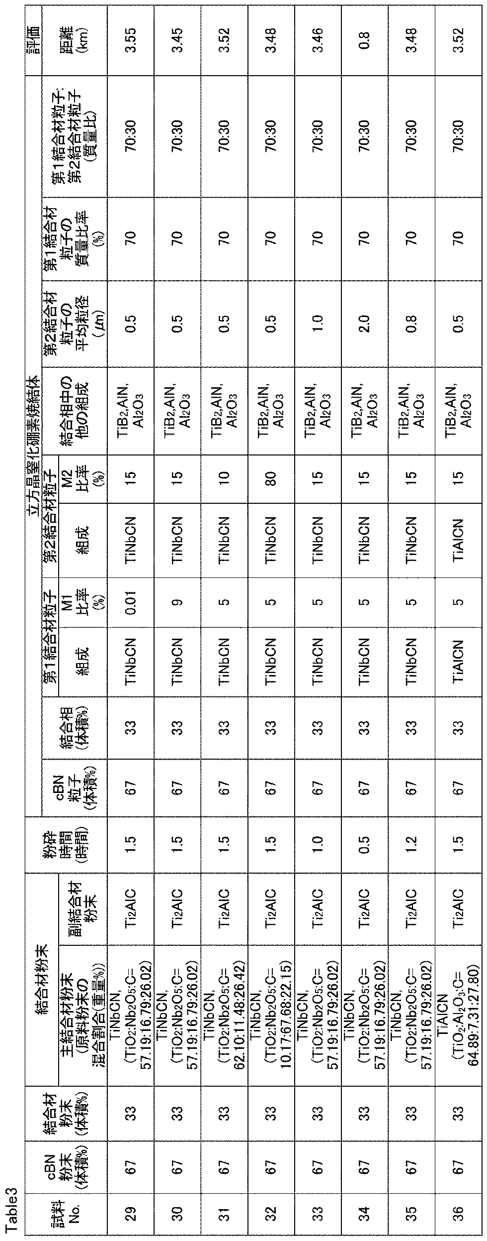
試料1、試料2、試料5~試料20、試料23~試料27、試料29~試料35、試料36のcBN焼結体は実施例に該当する。これらの試料のcBNは、工具の材料として用いた場合に、高強度焼入鋼の高能率加工においても、優れた工具寿命を示すことが確認された。
今回開示された実施の形態および実施例はすべての点で例示であって、制限的なものではないと考えられるべきである。本発明の範囲は上記した実施の形態および実施例ではなく請求の範囲によって示され、請求の範囲と均等の意味、および範囲内でのすべての変更が含まれることが意図される。
Claims (7)
- 20体積%以上80体積%以下の立方晶窒化硼素粒子と、20体積%以上80体積%以下の結合相と、を備える立方晶窒化硼素焼結体であって、
前記結合相は、第1結合材粒子と、第2結合材粒子とを含み、
前記第1結合材粒子及び前記第2結合材粒子のそれぞれは、チタンと、ジルコニウム、ハフニウム、周期律表の第5族元素、第6族元素及びアルミニウムからなる群より選ばれる少なくとも1種の第1金属元素と、窒素及び炭素の一方又は両方と、からなる1種の化合物を含み、
前記第1結合材粒子において、前記チタンの原子数及び前記第1金属元素の原子数の合計に対する、前記第1金属元素の原子数の比率は0.01%以上10%未満であり、
前記第2結合材粒子において、前記チタンの原子数及び前記第1金属元素の原子数の合計に対する、前記第1金属元素の原子数の比率は10%以上80%以下であり、
前記第2結合材粒子は、平均粒径が0.2μm以上1μm以下である、立方晶窒化硼素焼結体。 - 前記第2結合材粒子は、平均粒径が0.25μm以上0.7μm以下である、請求項1に記載の立方晶窒化硼素焼結体。
- 前記第1結合材粒子及び前記第2結合材粒子の合計質量に対する、前記第1結合材粒子の質量の比率は10%以上95%以下である、請求項1又は請求項2に記載の立方晶窒化硼素焼結体。
- 前記第1結合材粒子及び前記第2結合材粒子の合計質量に対する、前記第1結合材粒子の質量の比率は50%以上80%以下である、請求項1から請求項3のいずれか1項に記載の立方晶窒化硼素焼結体。
- 前記第1金属元素は、ジルコニウム、ハフニウム、ニオブ、タンタル、モリブデン及びタングステンからなる群より選ばれる少なくとも1種の金属元素からなる、請求項1から請求項4のいずれか1項に記載の立方晶窒化硼素焼結体。
- 前記第1金属元素は、ジルコニウム及びニオブの一方又は両方からなる、請求項1から請求項5のいずれか1項に記載の立方晶窒化硼素焼結体。
- 前記立方晶窒化硼素粒子の含有率は、35体積%以上75体積%以下である、請求項1から請求項6のいずれか1項に記載の立方晶窒化硼素焼結体。
Priority Applications (4)
| Application Number | Priority Date | Filing Date | Title |
|---|---|---|---|
| US17/626,051 US11518718B2 (en) | 2019-07-18 | 2020-07-17 | Cubic boron nitride sintered material |
| EP20841546.3A EP4001242B1 (en) | 2019-07-18 | 2020-07-17 | Cubic boron nitride sintered body |
| JP2021503622A JP6928196B2 (ja) | 2019-07-18 | 2020-07-17 | 立方晶窒化硼素焼結体 |
| CN202080051851.2A CN114144392B (zh) | 2019-07-18 | 2020-07-17 | 立方晶氮化硼烧结体 |
Applications Claiming Priority (2)
| Application Number | Priority Date | Filing Date | Title |
|---|---|---|---|
| JP2019-133028 | 2019-07-18 | ||
| JP2019133028 | 2019-07-18 |
Publications (1)
| Publication Number | Publication Date |
|---|---|
| WO2021010477A1 true WO2021010477A1 (ja) | 2021-01-21 |
Family
ID=74209881
Family Applications (1)
| Application Number | Title | Priority Date | Filing Date |
|---|---|---|---|
| PCT/JP2020/027904 Ceased WO2021010477A1 (ja) | 2019-07-18 | 2020-07-17 | 立方晶窒化硼素焼結体 |
Country Status (5)
| Country | Link |
|---|---|
| US (1) | US11518718B2 (ja) |
| EP (1) | EP4001242B1 (ja) |
| JP (1) | JP6928196B2 (ja) |
| CN (1) | CN114144392B (ja) |
| WO (1) | WO2021010477A1 (ja) |
Families Citing this family (1)
| Publication number | Priority date | Publication date | Assignee | Title |
|---|---|---|---|---|
| CN114922900B (zh) * | 2022-05-13 | 2023-08-08 | 咸阳职业技术学院 | 高温耐磨轴承及其制备方法 |
Citations (6)
| Publication number | Priority date | Publication date | Assignee | Title |
|---|---|---|---|---|
| JPH09136203A (ja) * | 1995-11-15 | 1997-05-27 | Mitsubishi Materials Corp | 高強度立方晶窒化硼素基焼結体 |
| JP2003236710A (ja) * | 2001-12-11 | 2003-08-26 | Mitsubishi Materials Corp | 耐チッピング性のすぐれた立方晶窒化ほう素基超高圧焼結材料製切削チップ |
| JP2007254249A (ja) * | 2006-03-27 | 2007-10-04 | Tungaloy Corp | cBN基超高圧焼結体 |
| JP2014214065A (ja) * | 2013-04-26 | 2014-11-17 | 株式会社タンガロイ | 立方晶窒化硼素焼結体および被覆立方晶窒化硼素焼結体 |
| JP2017030082A (ja) | 2015-07-30 | 2017-02-09 | 三菱マテリアル株式会社 | 耐欠損性にすぐれた立方晶窒化硼素焼結体切削工具 |
| JP2019133028A (ja) | 2018-01-31 | 2019-08-08 | Tianma Japan株式会社 | 表示装置 |
Family Cites Families (11)
| Publication number | Priority date | Publication date | Assignee | Title |
|---|---|---|---|---|
| JPH0621313B2 (ja) * | 1985-12-28 | 1994-03-23 | 住友電気工業株式会社 | 高硬度工具用焼結体およびその製造方法 |
| JP3035797B2 (ja) * | 1991-07-04 | 2000-04-24 | 三菱マテリアル株式会社 | 高強度を有する立方晶窒化ほう素基超高圧焼結材料製切削チップ |
| JPH07172924A (ja) * | 1993-12-17 | 1995-07-11 | Toshiba Tungaloy Co Ltd | 工具用高靭性焼結体およびその製造方法 |
| US5639285A (en) * | 1995-05-15 | 1997-06-17 | Smith International, Inc. | Polycrystallline cubic boron nitride cutting tool |
| JP5100927B2 (ja) * | 2001-01-30 | 2012-12-19 | 昭和電工株式会社 | 立方晶窒化ホウ素焼結体の製造方法 |
| JP4160898B2 (ja) * | 2003-12-25 | 2008-10-08 | 住友電工ハードメタル株式会社 | 高強度高熱伝導性立方晶窒化硼素焼結体 |
| CN100584797C (zh) * | 2004-10-28 | 2010-01-27 | 京瓷株式会社 | 立方氮化硼烧结材料以及利用其的切削工具 |
| JP6095162B2 (ja) * | 2013-03-29 | 2017-03-15 | 住友電工ハードメタル株式会社 | 立方晶窒化ホウ素焼結体 |
| WO2016143172A1 (ja) * | 2015-03-09 | 2016-09-15 | 住友電気工業株式会社 | セラミック粉末及び窒化ホウ素焼結体 |
| JP2017014084A (ja) * | 2015-07-03 | 2017-01-19 | 昭和電工株式会社 | 立方晶窒化硼素焼結体、立方晶窒化硼素焼結体の製造方法、工具、および切削工具 |
| US11383300B2 (en) * | 2017-10-30 | 2022-07-12 | Sumitomo Electric Industries, Ltd. | Sintered material and cutting tool including the same |
-
2020
- 2020-07-17 EP EP20841546.3A patent/EP4001242B1/en active Active
- 2020-07-17 JP JP2021503622A patent/JP6928196B2/ja active Active
- 2020-07-17 WO PCT/JP2020/027904 patent/WO2021010477A1/ja not_active Ceased
- 2020-07-17 CN CN202080051851.2A patent/CN114144392B/zh active Active
- 2020-07-17 US US17/626,051 patent/US11518718B2/en active Active
Patent Citations (6)
| Publication number | Priority date | Publication date | Assignee | Title |
|---|---|---|---|---|
| JPH09136203A (ja) * | 1995-11-15 | 1997-05-27 | Mitsubishi Materials Corp | 高強度立方晶窒化硼素基焼結体 |
| JP2003236710A (ja) * | 2001-12-11 | 2003-08-26 | Mitsubishi Materials Corp | 耐チッピング性のすぐれた立方晶窒化ほう素基超高圧焼結材料製切削チップ |
| JP2007254249A (ja) * | 2006-03-27 | 2007-10-04 | Tungaloy Corp | cBN基超高圧焼結体 |
| JP2014214065A (ja) * | 2013-04-26 | 2014-11-17 | 株式会社タンガロイ | 立方晶窒化硼素焼結体および被覆立方晶窒化硼素焼結体 |
| JP2017030082A (ja) | 2015-07-30 | 2017-02-09 | 三菱マテリアル株式会社 | 耐欠損性にすぐれた立方晶窒化硼素焼結体切削工具 |
| JP2019133028A (ja) | 2018-01-31 | 2019-08-08 | Tianma Japan株式会社 | 表示装置 |
Non-Patent Citations (1)
| Title |
|---|
| See also references of EP4001242A4 |
Also Published As
| Publication number | Publication date |
|---|---|
| EP4001242B1 (en) | 2025-09-24 |
| US11518718B2 (en) | 2022-12-06 |
| US20220204412A1 (en) | 2022-06-30 |
| JPWO2021010477A1 (ja) | 2021-09-13 |
| CN114144392B (zh) | 2023-06-02 |
| JP6928196B2 (ja) | 2021-09-01 |
| CN114144392A (zh) | 2022-03-04 |
| EP4001242A4 (en) | 2022-08-31 |
| EP4001242A1 (en) | 2022-05-25 |
Similar Documents
| Publication | Publication Date | Title |
|---|---|---|
| CN110573475B (zh) | 烧结体以及包含该烧结体的切削工具 | |
| US11767268B2 (en) | Cubic boron nitride sintered material | |
| JP6908798B2 (ja) | 立方晶窒化硼素焼結体 | |
| CN114867700B (zh) | 立方晶氮化硼烧结体 | |
| KR20220035124A (ko) | 입방정 질화붕소 소결체 및 그 제조 방법 | |
| JP6928197B2 (ja) | 立方晶窒化硼素焼結体 | |
| JP6928196B2 (ja) | 立方晶窒化硼素焼結体 | |
| WO2018092369A9 (ja) | 焼結体およびそれを含む切削工具 | |
| JP6912685B2 (ja) | 立方晶窒化硼素焼結体 | |
| JP6908799B2 (ja) | 立方晶窒化硼素焼結体 | |
| CN114787104B (zh) | 立方晶氮化硼烧结体 | |
| WO2022085161A1 (ja) | ダイヤモンド焼結体、及びダイヤモンド焼結体を備える工具 | |
| JP7252415B2 (ja) | ダイヤモンド焼結体、及びダイヤモンド焼結体を備える工具 | |
| WO2020036009A1 (ja) | 硬質材料、焼結体、粉末、及び、硬質材料の製造方法 |
Legal Events
| Date | Code | Title | Description |
|---|---|---|---|
| ENP | Entry into the national phase |
Ref document number: 2021503622 Country of ref document: JP Kind code of ref document: A |
|
| 121 | Ep: the epo has been informed by wipo that ep was designated in this application |
Ref document number: 20841546 Country of ref document: EP Kind code of ref document: A1 |
|
| NENP | Non-entry into the national phase |
Ref country code: DE |
|
| ENP | Entry into the national phase |
Ref document number: 2020841546 Country of ref document: EP Effective date: 20220218 |
|
| WWG | Wipo information: grant in national office |
Ref document number: 2020841546 Country of ref document: EP |