WO2021013010A1 - 天线单元和电子设备 - Google Patents
天线单元和电子设备 Download PDFInfo
- Publication number
- WO2021013010A1 WO2021013010A1 PCT/CN2020/102105 CN2020102105W WO2021013010A1 WO 2021013010 A1 WO2021013010 A1 WO 2021013010A1 CN 2020102105 W CN2020102105 W CN 2020102105W WO 2021013010 A1 WO2021013010 A1 WO 2021013010A1
- Authority
- WO
- WIPO (PCT)
- Prior art keywords
- antenna
- antenna branch
- branch
- floor
- feeder
- Prior art date
- Legal status (The legal status is an assumption and is not a legal conclusion. Google has not performed a legal analysis and makes no representation as to the accuracy of the status listed.)
- Ceased
Links
Images




Classifications
-
- H—ELECTRICITY
- H01—ELECTRIC ELEMENTS
- H01Q—ANTENNAS, i.e. RADIO AERIALS
- H01Q1/00—Details of, or arrangements associated with, antennas
- H01Q1/36—Structural form of radiating elements, e.g. cone, spiral, umbrella; Particular materials used therewith
-
- H—ELECTRICITY
- H01—ELECTRIC ELEMENTS
- H01Q—ANTENNAS, i.e. RADIO AERIALS
- H01Q1/00—Details of, or arrangements associated with, antennas
- H01Q1/12—Supports; Mounting means
- H01Q1/22—Supports; Mounting means by structural association with other equipment or articles
- H01Q1/24—Supports; Mounting means by structural association with other equipment or articles with receiving set
- H01Q1/241—Supports; Mounting means by structural association with other equipment or articles with receiving set used in mobile communications, e.g. GSM
- H01Q1/242—Supports; Mounting means by structural association with other equipment or articles with receiving set used in mobile communications, e.g. GSM specially adapted for hand-held use
- H01Q1/243—Supports; Mounting means by structural association with other equipment or articles with receiving set used in mobile communications, e.g. GSM specially adapted for hand-held use with built-in antennas
-
- H—ELECTRICITY
- H01—ELECTRIC ELEMENTS
- H01Q—ANTENNAS, i.e. RADIO AERIALS
- H01Q21/00—Antenna arrays or systems
- H01Q21/24—Combinations of antenna units polarised in different directions for transmitting or receiving circularly and elliptically polarised waves or waves linearly polarised in any direction
-
- H—ELECTRICITY
- H01—ELECTRIC ELEMENTS
- H01Q—ANTENNAS, i.e. RADIO AERIALS
- H01Q1/00—Details of, or arrangements associated with, antennas
- H01Q1/36—Structural form of radiating elements, e.g. cone, spiral, umbrella; Particular materials used therewith
- H01Q1/38—Structural form of radiating elements, e.g. cone, spiral, umbrella; Particular materials used therewith formed by a conductive layer on an insulating support
-
- H—ELECTRICITY
- H01—ELECTRIC ELEMENTS
- H01Q—ANTENNAS, i.e. RADIO AERIALS
- H01Q1/00—Details of, or arrangements associated with, antennas
- H01Q1/48—Earthing means; Earth screens; Counterpoises
-
- H—ELECTRICITY
- H01—ELECTRIC ELEMENTS
- H01Q—ANTENNAS, i.e. RADIO AERIALS
- H01Q1/00—Details of, or arrangements associated with, antennas
- H01Q1/50—Structural association of antennas with earthing switches, lead-in devices or lightning protectors
-
- H—ELECTRICITY
- H01—ELECTRIC ELEMENTS
- H01Q—ANTENNAS, i.e. RADIO AERIALS
- H01Q1/00—Details of, or arrangements associated with, antennas
- H01Q1/52—Means for reducing coupling between antennas; Means for reducing coupling between an antenna and another structure
- H01Q1/521—Means for reducing coupling between antennas; Means for reducing coupling between an antenna and another structure reducing the coupling between adjacent antennas
- H01Q1/523—Means for reducing coupling between antennas; Means for reducing coupling between an antenna and another structure reducing the coupling between adjacent antennas between antennas of an array
-
- H—ELECTRICITY
- H01—ELECTRIC ELEMENTS
- H01Q—ANTENNAS, i.e. RADIO AERIALS
- H01Q19/00—Combinations of primary active antenna elements and units with secondary devices, e.g. with quasi-optical devices, for giving the antenna a desired directional characteristic
- H01Q19/10—Combinations of primary active antenna elements and units with secondary devices, e.g. with quasi-optical devices, for giving the antenna a desired directional characteristic using reflecting surfaces
- H01Q19/12—Combinations of primary active antenna elements and units with secondary devices, e.g. with quasi-optical devices, for giving the antenna a desired directional characteristic using reflecting surfaces wherein the surfaces are concave
- H01Q19/13—Combinations of primary active antenna elements and units with secondary devices, e.g. with quasi-optical devices, for giving the antenna a desired directional characteristic using reflecting surfaces wherein the surfaces are concave the primary radiating source being a single radiating element, e.g. a dipole, a slot, a waveguide termination
-
- H—ELECTRICITY
- H01—ELECTRIC ELEMENTS
- H01Q—ANTENNAS, i.e. RADIO AERIALS
- H01Q19/00—Combinations of primary active antenna elements and units with secondary devices, e.g. with quasi-optical devices, for giving the antenna a desired directional characteristic
- H01Q19/10—Combinations of primary active antenna elements and units with secondary devices, e.g. with quasi-optical devices, for giving the antenna a desired directional characteristic using reflecting surfaces
- H01Q19/12—Combinations of primary active antenna elements and units with secondary devices, e.g. with quasi-optical devices, for giving the antenna a desired directional characteristic using reflecting surfaces wherein the surfaces are concave
- H01Q19/17—Combinations of primary active antenna elements and units with secondary devices, e.g. with quasi-optical devices, for giving the antenna a desired directional characteristic using reflecting surfaces wherein the surfaces are concave the primary radiating source comprising two or more radiating elements
-
- H—ELECTRICITY
- H01—ELECTRIC ELEMENTS
- H01Q—ANTENNAS, i.e. RADIO AERIALS
- H01Q21/00—Antenna arrays or systems
- H01Q21/0006—Particular feeding systems
-
- H—ELECTRICITY
- H01—ELECTRIC ELEMENTS
- H01Q—ANTENNAS, i.e. RADIO AERIALS
- H01Q9/00—Electrically-short antennas having dimensions not more than twice the operating wavelength and consisting of conductive active radiating elements
- H01Q9/04—Resonant antennas
- H01Q9/16—Resonant antennas with feed intermediate between the extremities of the antenna, e.g. centre-fed dipole
-
- H—ELECTRICITY
- H01—ELECTRIC ELEMENTS
- H01Q—ANTENNAS, i.e. RADIO AERIALS
- H01Q9/00—Electrically-short antennas having dimensions not more than twice the operating wavelength and consisting of conductive active radiating elements
- H01Q9/04—Resonant antennas
- H01Q9/16—Resonant antennas with feed intermediate between the extremities of the antenna, e.g. centre-fed dipole
- H01Q9/28—Conical, cylindrical, cage, strip, gauze, or like elements having an extended radiating surface; Elements comprising two conical surfaces having collinear axes and adjacent apices and fed by two-conductor transmission lines
- H01Q9/285—Planar dipole
Definitions
- the present disclosure relates to the field of antenna technology, and more particularly to an antenna unit and electronic equipment.
- the forms of antennas mainly include patch antennas, Yagi-Uda antennas, and dipole antennas.
- the floor is generally used as the reflector of the horizontally polarized dipole antenna.
- the floor has a poor reflection effect on the antenna signal, and the beam transmission performance of the horizontally polarized dipole antenna is poor, and it cannot meet the requirements of high directivity radiation.
- the embodiments of the present disclosure provide an antenna unit and an electronic device to solve the problem of poor reflection effect of the antenna signal on the floor of the horizontally polarized dipole antenna of the related art.
- an antenna unit including:
- a substrate the substrate having a floor
- a horizontally polarized dipole antenna includes a first antenna branch and a second antenna branch, the first antenna branch and the second antenna branch are arranged in the substrate at intervals, so The first antenna branch and the second antenna branch are both located on the plane where the floor is located;
- a first feeding structure where the first antenna branch and the second antenna branch are electrically connected to the floor through the first feeding structure;
- the floor is spaced from the first antenna branch and the second antenna branch, and the sides of the floor facing the first antenna branch and the second antenna branch are concave sides.
- an embodiment of the present disclosure provides an electronic device including the antenna unit described in the first aspect of the embodiment of the present disclosure.
- the side of the floor facing the horizontally polarized dipole antenna as a concave side
- the side of the floor close to the horizontally polarized dipole antenna can form a concave reflecting surface
- most of the beams of the horizontally polarized dipole antenna can be radiated toward the front end, which improves the reflection effect of the floor on the antenna signal and enhances the beam transmission performance of the horizontally polarized dipole antenna , So that the horizontally polarized dipole antenna can meet the radiation requirements of high directivity.
- FIG. 1 is a schematic diagram of a planar structure of an antenna unit provided by an embodiment of the present disclosure
- FIG. 2 is a schematic diagram of a floor structure provided by an embodiment of the present disclosure
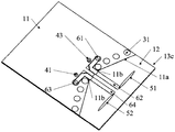
- FIG. 3 is a schematic diagram of a three-dimensional structure of an antenna unit provided by an embodiment of the present disclosure
- FIG. 4 is a schematic cross-sectional structure diagram of an antenna unit provided by an embodiment of the present disclosure.
- 5 to 8 are schematic diagrams of layered structures of antenna units provided by embodiments of the present disclosure.
- FIG. 9 is a schematic diagram of a side structure of an antenna unit provided by an embodiment of the present disclosure.
- FIG. 10 is a simulation diagram of the reflection coefficient of the antenna unit provided by an embodiment of the present disclosure.
- Fig. 11 is a 26GHz horizontally polarized dipole pattern of the antenna unit provided by an embodiment of the present disclosure
- Fig. 12 is a 26 GHz vertical polarization dipole pattern of the antenna unit provided by an embodiment of the present disclosure
- 13 is a 28GHz horizontally polarized dipole pattern of the antenna unit provided by an embodiment of the present disclosure
- 15 is a 39GHz horizontally polarized dipole pattern of the antenna unit provided by an embodiment of the present disclosure
- Fig. 16 is a 39GHz vertical polarization dipole pattern of the antenna unit provided by an embodiment of the present disclosure
- FIG. 17 is one of structural schematic diagrams of an antenna array provided by an embodiment of the present disclosure.
- FIG. 18 is the second structural diagram of the antenna array provided by an embodiment of the present disclosure.
- an antenna unit including:
- the substrate 1, the substrate 1 has a floor 11;
- the horizontally polarized dipole antenna 5 includes a first antenna branch 51 and a second antenna branch 52.
- the first antenna branch 51 and the second antenna branch 52 are arranged in the substrate 1 at intervals.
- the antenna branch 51 and the second antenna branch 52 are both located on the plane where the floor 11 is located;
- the first feeding structure 6, the first antenna branch 51 and the second antenna branch 52 are electrically connected to the floor 11 through the first feeding structure 6;
- the floor 11 is spaced apart from the first antenna branch 51 and the second antenna branch 52, and the side of the floor 11 facing the first antenna branch 51 and the second antenna branch 52 is a concave side 11a.
- the first antenna branch 51 and the second antenna branch 52 of the horizontally polarized dipole antenna 5 are both laterally (or horizontally) arranged in the substrate 1.
- the first antenna branch 51 and the second antenna branch 52 may be arranged in the substrate 1 parallel to the substrate 1, or may be arranged in the substrate 1 slightly offset from the parallel direction.
- the central axes of the first antenna branch 51 and the second antenna branch 52 may be completely coincident, or may be slightly offset from each other by a certain angle, or slightly deviated by a certain distance.
- the length of the first antenna branch 51 and the length of the second antenna branch 52 may be equal to or approximately the same.
- the length of the first antenna branch 51 and the second antenna branch 52 is approximately one-quarter of the medium wavelength.
- the above-mentioned first antenna branch 51 and second antenna branch 52 are both located on the plane where the floor 11 is located. In this way, the floor 11 can be used as a reflector of the horizontally polarized dipole antenna 5, and can be used for the beam of the horizontally polarized dipole antenna 5. Reflect.
- the first antenna branch 51 and the second antenna branch 52 can be set in the clearance area.
- Zone 12 the first feeding structure 6 extends from the clearance zone 12 to the area where the floor 11 is located.
- the side of the floor close to the horizontally polarized dipole antenna can form a concave reflecting surface
- most of the beams of the horizontally polarized dipole antenna can be radiated toward the front end, which improves the reflection effect of the floor on the antenna signal and enhances the beam transmission of the horizontally polarized dipole antenna Performance, so that the horizontal polarization dipole antenna can meet the radiation requirements of high directivity.
- the antenna unit of the embodiment of the present disclosure can be set as a millimeter wave antenna unit, which is suitable for signal transmission in the 5G millimeter wave band. That is, the horizontally polarized dipole antenna 5 may be a millimeter wave antenna, and the length of the first antenna branch 51 and the second antenna branch 52 of the horizontally polarized dipole antenna 5 may be set according to the millimeter wave wavelength.
- the concave side 11a of the floor 11 can form a concave reflecting surface, making the structure of the antenna unit more compact, and the size of the dielectric substrate at the front end of the horizontal dipole antenna 5 is relatively small.
- the concave reflecting surface of the floor 11 is similar to a cavity structure.
- Such a cavity structure can cause the horizontally polarized dipole antenna 5 to resonate, thereby generating another frequency point, such as a frequency point of 39 GHz.
- the horizontally polarized dipole antenna 5 can cover the three frequency bands n257, n260, and n261, while the roaming frequency band can cover the n258 frequency band.
- the shape of the first antenna branch 51 and the second antenna branch 52 can be rectangular, triangular, or elliptical.
- the shape changes smoothly, causing the impedance of the antenna to change It is more gentle, which is beneficial to expand the bandwidth of the horizontally polarized dipole antenna 5.
- the concave side 11a of the floor 11 has an arc shape, such as a parabola, hyperbola, elliptical arc, or circular arc, etc.; or,
- the recessed side 11a of the floor 11 includes a first straight section A located in the middle area, and a second straight section B and a third straight section C located on both sides.
- the second straight section B and the first straight section The angle between section A is an obtuse angle, and the angle between the third straight section C and the first straight section A is an obtuse angle.
- the second straight section B and the third straight section C are symmetrically arranged relative to the first straight section A.
- the first power feeding structure 6 includes:
- the first feeding point 61 is electrically connected to the floor 11;
- the first feeder 62 one end of the first feeder 62 is electrically connected to the first antenna branch 51, and the other end of the first feeder 62 is electrically connected to the first feed point 61;
- the second feeding point 63 is electrically connected to the floor 11;
- the second feeder 64 one end of the second feeder 64 is electrically connected to the second antenna branch 52, and the other end of the second feeder 64 is electrically connected to the second feed point 64.
- the above-mentioned feeding structure of the horizontally polarized dipole antenna 5, that is, the first feeding structure 6 can adopt double-end feeding, and the two feeders of each group of feeding structures have the same amplitude and phase difference of 180°.
- the horizontally polarized dipole antenna 5 can adopt a differential feeding mode.
- the use of differential feed can improve the common mode rejection and anti-interference ability of the antenna, and can improve the differential end-to-end isolation (isolation) and the purity of polarization.
- the radiation power of the antenna can be improved.
- both antenna branches of the horizontally polarized dipole antenna 5 adopt coaxial line differential feeding.
- the first feeder 62 and the second feeder 64 are mainly composed of: a coplanar wave guide (CPW) connected to a coaxial line and then connected to the first antenna branch 51 and the second antenna branch 52 respectively.
- CPW coplanar wave guide
- the floor 11 is provided with a first feeder trough 11c and a second feeder trough 11d communicating with the recessed side 11a;
- the other end of the first feeder 62 is electrically connected to the first feeding point 61 through the first feeder trough 11c
- the other end of the second feeder 64 is electrically connected to the second feeder 63 through the second feeder trough 11d
- the first feeder 62 There is a gap 11b between the second feeder 64 and the floor 11.
- the width of the first feeder slot 11c is greater than the width of the first feeder 62
- the width of the second feeder slot 11d is greater than the width of the second feeder 64.
- the first feeder groove 11c and the second feeder groove 11d may be through grooves, that is, grooves that penetrate the floor 11, or grooves that do not penetrate the floor 11.
- first feeder trough 11c and the second feeder trough 11d do not penetrate the floor 11, an insulating layer can be provided at the bottom of the first feeder trough 11c and the second feeder trough 11d, so that the first feeder 62 and the second feeder 64 are connected to each other.
- the floors 11 are insulated.
- the first feeder 62 and the second feeder 64 are used as coplanar waveguide transmission lines.
- the gaps 11b between the first feeder 62 and the second feeder 64 and the floor 11 are generally used to adjust the impedance of the coplanar waveguide transmission line.
- the entire common The impedance of the planar waveguide transmission line is adjusted to be close to 50 ohms. By adjusting the impedance of the coplanar waveguide transmission line, it is helpful to reduce signal reflection, so as to send more energy to the antenna for feeding.
- the size of the gap 11b can be determined by factors such as the thickness of the dielectric layer of the substrate 1, the dielectric constant of the dielectric layer, and the signal line width of the coplanar waveguide transmission line (that is, the width of the first feeder 62 and the second feeder 64).
- the concave side 11a of the floor 11 includes the first straight section A located in the middle area, and the second straight section B and the third straight section C located on both sides of the area as an example.
- Section B and the third straight section C both gradually extend from the first straight section A to the direction of the horizontally polarized dipole antenna 5, so that the second straight section B and the third straight section C are not coplanar
- the impedance of the waveguide transmission line is referenced to the ground, so part of the energy of the first feeder 62 and the second feeder 64 can be coupled to the second straight section B and the third straight section C through the gap 11b, so that the second straight section B and the third straight section C Segments C respectively form current paths D, as shown in FIG. 2, which is more conducive to resonating the horizontally polarized dipole antenna 5, thereby generating another frequency point, such as a frequency point of 39 GHz.
- the antenna unit of the embodiment of the present disclosure may only be provided with a horizontally polarized dipole antenna as a single-polarized dipole antenna.
- the antenna unit of the embodiment of the present disclosure may also be configured as a dual-polarized dipole antenna. The specific implementation of the dual-polarized dipole antenna will be described below.
- the antenna unit may further include:
- the vertically polarized dipole antenna 2 includes a third antenna branch 21 and a fourth antenna branch 22, and the third antenna branch 21 and the fourth antenna branch 22 are arranged in the substrate 1 at intervals;
- the reflector 3 includes a plurality of reflecting columns 31, which are arranged in the substrate 1 at intervals along a parabola;
- the second feeding structure 4, the third antenna branch 21 and the fourth antenna branch 22 are electrically connected to the floor 11 through the second feeding structure 4;
- first antenna branch 51, the second antenna branch 52, the third antenna branch 21, and the fourth antenna branch 22 are all located on the side where the focal point of the parabola is located;
- the third antenna branch 21 and the fourth antenna branch 22 are respectively located on both sides of the plane where the first antenna branch 51 and the second antenna branch 52 are located, and the first antenna branch 51 and the second antenna branch 52 are respectively located in the third antenna branch 21 and the second antenna branch.
- the third antenna branch 21 and the fourth antenna branch 22 of the vertically polarized dipole antenna 2 are both vertically arranged in the substrate 1.
- the third antenna branch 21 and the fourth antenna branch 22 may be arranged in the substrate 1 perpendicular to the substrate 1, or may be arranged in the substrate 1 slightly deviated from the vertical direction.
- the central axis of the third antenna branch 21 and the central axis of the second antenna 22 may be completely coincident, or may be slightly offset from each other by a certain angle, or slightly offset by a certain distance.
- the length of the third antenna branch 21 and the length of the fourth antenna branch 22 may be equal to or approximately the same, and the length of the third antenna branch 21 and the fourth antenna branch 22 is approximately one-quarter of the medium wavelength.
- each reflecting column 31 in the substrate 1 should be matched with the third antenna branch 21 and the fourth antenna branch 22, so that each reflector
- the column 31 also needs to be vertically arranged in the substrate 1.
- each reflective column 31 may be arranged in the substrate 1 perpendicular to the substrate 1, or may be arranged in the substrate 1 slightly offset from the vertical direction.
- the vertically polarized dipole antenna is combined with the horizontally polarized dipole antenna to realize the design of the dual polarized dipole antenna.
- it can implement Multiple Input and Multiple Output (MIMO) functions to increase the data transmission rate; on the other hand, it can increase the wireless connection capability of the antenna, reduce the probability of communication disconnection, and improve the communication effect. user experience.
- MIMO Multiple Input and Multiple Output
- the vertically polarized dipole antenna 2 and the horizontally polarized dipole antenna 5 are staggered in the vertical direction (that is, the direction perpendicular to the substrate 1), they are arranged in the horizontal direction (that is, parallel to the substrate).
- the positional relationship between the vertically polarized dipole antenna 2 and the horizontally polarized dipole antenna 5 may not be limited.
- the vertically polarized dipole antenna 2 may be located in the area between the horizontally polarized dipole antenna 5 and the reflector 3, or the horizontally polarized dipole antenna 5 may be located in the vertically polarized dipole antenna 2.
- the area between the reflector 3 and the vertically polarized dipole antenna 2 and the horizontally polarized dipole antenna 5 may be located on the same vertical plane.
- FIG. 1 and 3 show an embodiment in which the first antenna branch 51 and the second antenna branch 52 are both located in the area between the vertically polarized dipole antenna 2 and the reflector 3. In this embodiment, it is possible to save The space of the clearance area 12 occupied by the horizontally polarized dipole antenna 5 and the vertically polarized dipole antenna 2.
- the vertically polarized dipole antenna 2 and the reflector 3 arranged along the parabola in the substrate 1, and setting the vertically polarized dipole antenna 2 on the side where the focus of the parabola is located Therefore, most of the beams of the vertically polarized dipole antenna 2 are radiated toward the front end, and the backward radiation is reduced, so that the end-fire performance of the dipole antenna can be enhanced.
- the vertically polarized dipole antenna 2 of the embodiment of the present disclosure can also be a millimeter wave antenna, so as to be suitable for signal transmission in the 5G millimeter wave band.
- the third vertical polarized dipole antenna 2 The length of the antenna branch 21 and the fourth antenna branch 22 can be set according to the millimeter wave wavelength.
- the antenna unit of the embodiment of the present disclosure may be configured as a millimeter wave antenna unit, that is, both the vertically polarized dipole antenna 2 and the horizontally polarized dipole antenna 5 are millimeter wave antennas.
- the global mainstream 5G millimeter wave band defined by the 3rd Generation Partnership Project (3GPP) includes n258 (24.25-27.5GHz) based on 26GHz, n257 (26.5-29.5GHz), n261 (27.5) based on 28GHz -28.35GHz), n260 (37.0-40.0GHz) based on 39GHz.
- 3GPP 3rd Generation Partnership Project
- the structure of the floor 11 can cause the horizontally polarized dipole antenna 5 to resonate, thereby generating another frequency point, such as a frequency of 39 GHz, so that the horizontally polarized dipole antenna 5 can cover n257,
- the three frequency bands n260 and n261, while roaming frequency band can cover the n258 frequency band.
- the reflecting columns 31 are similar to a cavity structure, which can also cause the vertically polarized dipole antenna 2 to resonate, thereby generating Another frequency point, such as the frequency point of 39 GHz, allows the vertically polarized dipole antenna 2 to cover the three frequency bands n257, n260, and n261, while the roaming frequency band can cover n258.
- the reflection coefficient graph shown in Figure 10 shows that the horizontally polarized dipole antenna and the vertical
- the common bandwidth of the -10dB S parameter of the polarized dipole is 26.3GHz-29.5GHz and 36.2GHz-41.5GHz
- the common bandwidth of the -6dB S parameter is 24.2GHz-30.8GHz and 34.7GHz-42.3GHz, which basically covers
- the global mainstream 5G millimeter wave frequency bands n257, n260, and n261 defined by 3GPP are adopted, and the roaming frequency band can cover n258.
- Figures 11 to 16 respectively show the corresponding directional patterns of the dual-polarized dipole antenna at 26.0 GHz, 28.0 GHz and 39.0 GHz frequency points. It can be seen from the figure that they are all end-fire radiation patterns, with less backward radiation.
- the substrate 1 As mentioned above, a part of the substrate 1 is provided with the floor 11 on the left side of the substrate 1, and the right side of the substrate 1 is the clearance area 12. In this way, the reflector 3 as a whole can be installed in the area where the floor 11 is located. Both the three antenna branches 21 and the fourth antenna branch 22 can be arranged in the clearance area 12, and the second feed structure 4 extends from the clearance area 12 to the area where the floor 11 is located.
- each reflection post 31 penetrates the floor 11, and the distance between the reflection post 31 and the concave side 11a is smaller than the distance between the reflection post 31 and the opposite side of the concave side 11a. That is to say, each reflection post 31 is arranged close to the concave side 11 a of the floor 11, or in other words, each reflection post 31 is located at the edge area of the floor 11 close to the clearance area 12.
- the distance between the reflector 3 and the vertically polarized dipole antenna 2 can be shortened, the reflection effect of the reflector 3 on the vertically polarized dipole antenna 2 can be improved, and the vertically polarized dipole antenna can be improved The front-to-back ratio of the 2 direction map.
- the horizontal space of the floor 11 area occupied by the reflector 3 as a whole can be reduced, and more floor 11 areas can be reserved for other components.
- the reflecting columns 31 on both sides of the reflector 3 are located at the junction of the floor 11 and the clearance area 12, or in other words, the reflecting columns 31 on both sides of the reflector 3 are partially located in the area where the floor 11 is located, and partially located Clearance area 12.
- the spacing between the adjacent reflecting columns 31 of the reflector 3 may be all equal, or partly equal. In order to improve the reflection effect of the reflector 3, the spacing between the adjacent reflecting columns 31 should not be too large. If a certain adjacent reflecting column 31 of the reflector 3 needs to pass through related components, the adjacent reflecting column 31 The spacing between the two can be appropriately increased, and the spacing between other adjacent reflective columns 31 can be relatively reduced. 1, 3, etc. show an embodiment in which the distance between the middle two reflective columns 31 of the reflector 3 is relatively large, and the distances between other adjacent reflective columns 31 are all equal.
- the central axis of the third antenna branch 21 and the central axis of the fourth antenna branch 22 both pass through the focal point of the parabola. In this way, the gain of the vertically polarized dipole antenna 2 can be increased, and the front-to-back ratio of its pattern can be improved.
- the third antenna branch 21 and the fourth antenna branch 22 are symmetrical with respect to the plane where the first antenna branch 51 and the second antenna branch 52 are located;
- the first antenna branch 51 and the second antenna branch 52 are symmetrical with respect to the third antenna branch 21 and the fourth antenna branch 22.
- the two antenna branches of the horizontally polarized dipole antenna are inserted into the middle position between the two antenna branches of the vertically polarized dipole antenna, and the two antenna branches of the vertically polarized dipole antenna are inserted into the horizontal pole.
- the intermediate position between the two antenna branches of the dipole antenna maintains strict horizontal and vertical symmetry in the overall structure, thereby preventing the angular deviation of the main radiation direction of the pattern.
- the second power feeding structure 4 includes:
- the third feeding point 41 is electrically connected to the floor 11;
- the third feeder 42 one end of the third feeder 42 is electrically connected to the third antenna branch 21, and the other end of the third feeder 42 is electrically connected to the third feed point 41;
- the fourth feeding point 43 is electrically connected to the floor 11;
- the fourth feeder 44 one end of the fourth feeder 44 is electrically connected to the fourth antenna branch 22, and the other end of the fourth feeder 44 is electrically connected to the fourth feed point 43;
- the signal sources connected by the two feeders have the same amplitude and a phase difference of 180°. That is to say, both the vertically polarized dipole antenna 2 and the horizontally polarized dipole antenna 5 adopt a differential feeding mode.
- the use of differential feed can improve the common mode rejection and anti-interference ability of the antenna, and can improve the differential end-to-end isolation (isolation) and the purity of polarization.
- the radiation power of the antenna can be improved.
- the two antenna branches of the vertically polarized dipole antenna 2 both adopt coaxial line differential feed
- the two antenna branches of the horizontally polarized dipole antenna 5 both adopt coaxial line differential feed.
- the multi-layer circuit substrate (LTCC) process is used for processing, in other words, when the substrate 1 includes a multi-layer dielectric board 13, a radio frequency integrated circuit (RFIC) chip can be buried in the dielectric board 13, directly The vertically polarized dipole antenna 2 feeds power, thereby shortening the length of the third feeder 42 and the fourth feeder 44 and reducing the loss.
- LTCC multi-layer circuit substrate
- RFIC radio frequency integrated circuit
- the substrate 1 includes N layers of dielectric plates 13, and N is greater than or equal to 4;
- the first antenna branch 51 and the second antenna branch 52 are arranged in the same-layer dielectric board 13;
- the third antenna branch 21 and the fourth antenna branch 22 are respectively arranged in two non-adjacent dielectric plates 13, and the third antenna branch 21 and the fourth antenna branch 22 respectively penetrate the corresponding dielectric plate 13;
- the reflector 3 penetrates the N-layer dielectric plate 13 as a whole.
- each reflection column 31 of the reflector 3 penetrates the N-layer dielectric plate 13.
- the substrate 1 is configured as a multi-layer dielectric board 13, so that the corresponding dielectric board 13 can be processed separately to form the third antenna branch 21, the fourth antenna branch 22 and the reflector 3, which can simplify the antenna unit Craftsmanship.
- the lengths of the third antenna branch 21, the fourth antenna branch 22, and the reflection column 31 can be easily controlled, and the length of the third antenna branch 21 and the fourth antenna branch 22 can be easily controlled.
- the length of the third antenna branch 21 and the fourth antenna branch 22 can be controlled more accurately, so that the length of the third antenna branch 21 and the fourth antenna branch 22 is as close as possible to a quarter of the wavelength of the medium. Improve the performance of the antenna unit.
- each reflection post 31 of the reflector 3 penetrates the N-layer dielectric plate 13 so that the vertically polarized dipole antenna 2 is located in the reflection area of the reflector 3, which can further improve the reflection effect.
- the third antenna branch 21 and the fourth antenna branch 22 may not penetrate the corresponding dielectric plate 13.
- the reflector 3 may not penetrate all the layers of the dielectric plates 13.
- the substrate 1 has 6 layers of dielectric plates 13, and the outermost two layers of dielectric plates 13 are not used for arranging the third antenna branch 21 and the fourth antenna.
- Branch 22, the two layers of dielectric plates 13 do not need to be provided with reflectors 3, or in other words, the reflectors 3 do not need to penetrate the outermost two layers of dielectric plates 13.
- the substrate 1 includes four layers of dielectric plates 13, and the third antenna branch 21 is provided on the first layer of dielectric plate 13a, and the fourth antenna branch 22 is provided on the fourth layer of dielectric plate 13d. .
- the third antenna branch 21 and the fourth antenna branch 22 are respectively formed by metal pillars penetrating the corresponding dielectric plate 13;
- Each reflection column 31 of the reflector 3 is formed by a number of metal columns penetrating through the N-layer dielectric plate 13.
- the dielectric plate 13 corresponding to the third antenna branch 21 and the fourth antenna branch 22 is provided with a through hole (not shown in the figure) that penetrates the dielectric plate 13 vertically, and the third antenna branch 21 and the fourth antenna branch 22 It is formed by metal pillars filled in through holes.
- the N-layer dielectric plate 13 is spaced along a parabola with a plurality of through holes vertically penetrating the N-layer dielectric plate 13, and each reflection column 31 of the reflector 3 is formed by metal columns filled in the plurality of through holes.
- the third antenna branch 21, the fourth antenna branch 22 and the reflection column 31 are formed by punching holes in the dielectric plate 13 and inserting metal pillars into the holes. The process is simple and mature, and no additional production cost is added. .
- the reflector 3 as a whole can be located on the edge area of the floor 11 close to the clearance area 12 .
- the third feeding point 41 and the fourth feeding point 43 are located on the side of the reflector 3 away from the vertically polarized dipole antenna 2; the first feeding point 61 and the second feeding point 63 Located on the side of the reflector 3 away from the horizontally polarized dipole antenna 5.
- the third feeder 42, the fourth feeder 44, the first feeder 62 and the second feeder 64 all need to pass through the gap between the reflection columns 31 of the reflector 3. Therefore, the gap between the reflective columns 31 can be flexibly adjusted according to the arrangement of the feeder.
- the third feeder 42, the fourth feeder 44, the first feeder 62 and the second feeder 64 respectively pass through the gap between the middle two adjacent reflecting columns 31 of the reflector 3 to the corresponding feeding point. Therefore, the gap between the two adjacent reflection posts 31 in the middle of the reflector 3 can be appropriately increased, so that each feeder can pass directly.
- the two antenna branches of the vertically polarized dipole antenna 2 are both located in the middle position between the two antenna branches of the horizontally polarized dipole antenna 5. Therefore, in the horizontal direction, the third feeder 42 and the fourth feeder 44 are both located between the first feeder 62 and the second feeder 64, respectively.
- the substrate 1 includes the multilayer dielectric plate 13
- the following embodiments can be adopted for the arrangement of the components of the above-mentioned dual-polarized dipole antenna.
- the substrate 1 includes four layers of dielectric plates 13;
- the third antenna branch 21 is arranged in the first layer of dielectric plate 13a and penetrates the first layer of dielectric plate 13a;
- the third feeder 42 is arranged on the surface of the second layer of dielectric plate 13b close to the first layer of dielectric plate 13a;
- the first antenna branch 51, the second antenna branch 52, the first feeder 62, the second feeder 64 and the floor 11 are all arranged on the surface of the third layer of dielectric plate 13c close to the second layer of dielectric plate 13b;
- the fourth feeder 44 is arranged on the surface of the fourth layer of dielectric plate 13d close to the third layer of dielectric plate 13c;
- the fourth antenna branch 22 is arranged in the fourth layer of dielectric plate 13d and penetrates the fourth layer of dielectric plate 13d;
- the reflector 3 penetrates the four-layer dielectric plate 13, that is, the reflector 3 penetrates the first-layer dielectric plate 13a to the fourth-layer dielectric plate 13d.
- the floor 11 can be used as a reflector for the first antenna branch 51 and the second antenna branch 52. Better improve its reflection performance.
- the fourth layer of dielectric plate 13d can also be located close to the third layer of dielectric plate.
- a floor 11 is provided on the surface of 13c. In order to ensure the symmetry between the floor 11 and each antenna branch and improve the working performance of each antenna branch, the floor 11 can be provided only on the surface of the third layer of dielectric plate 13c close to the second layer of dielectric plate 13b.
- each reflection column 31 of the reflector 3 penetrates the first layer of dielectric plate 13a to the fourth layer of dielectric plate 13d.
- the antenna unit of the embodiment of the present disclosure can be applied to Wireless Metropolitan Area Network (WMAN), Wireless Wide Area Network (WWAN), Wireless Local Area Network (WLAN), and Wireless Personal Area Network (WMAN).
- Wireless Personal Area Network (WPAN) Multiple Input Multiple Output (MIMO), Radio Frequency Identification (RFID), Near Field Communication (NFC), Wireless Charging (Wireless Power Consortium, WPC), Frequency Modulation (Frequency) Modulation, FM) and other wireless communication scenarios.
- the antenna unit of the embodiment of the present disclosure can also be applied to the compliance testing, design and application of SAR and HAC and other wearable electronic devices related to human safety and health (such as hearing aids or heart rate regulators).
- the embodiment of the present disclosure also relates to an electronic device including the antenna unit of any one of the embodiments of the present disclosure.
- the specific implementation of the antenna unit in the electronic device can be referred to the above description, and can achieve the same technical effect. In order to avoid repetition, this will not be repeated.
- the number of antenna elements is greater than or equal to 2, and the antenna elements are arranged in sequence to form an antenna array.
- an isolator 9 is provided between two adjacent antenna units.
- the isolator 9 By arranging the isolator 9 between the adjacent antenna units, the mutual coupling between the adjacent antenna units can be effectively reduced, and the working performance of the antenna array is guaranteed.
- the isolator 9 includes a plurality of spacers 91 arranged at intervals, and the spacers 91 are perpendicular to the substrate 1 and penetrate the substrate 1.
- the above-mentioned electronic devices can be computers (Computer), mobile phones, tablet computers (Tablet Computer), laptop computers (Laptop Computer), personal digital assistants (personal digital assistant, PDA), mobile Internet devices (Mobile Internet Device, MID) ), wearable devices, e-readers, navigators, digital cameras, etc.
- computers Computer
- Tablet Computer Tablet Computer
- laptop computers laptop computers
- personal digital assistants personal digital assistant, PDA
- mobile Internet devices Mobile Internet Device, MID)
- wearable devices e-readers, navigators, digital cameras, etc.
Landscapes
- Engineering & Computer Science (AREA)
- Computer Networks & Wireless Communication (AREA)
- Aerials With Secondary Devices (AREA)
- Variable-Direction Aerials And Aerial Arrays (AREA)
Abstract
Description
Claims (14)
- 一种天线单元,包括:基板,所述基板具有地板;水平极化偶极子天线,所述水平极化偶极子天线包括第一天线枝和第二天线枝,所述第一天线枝和所述第二天线枝间隔设置于所述基板中,所述第一天线枝和所述第二天线枝均位于所述地板所在的平面;第一馈电结构,所述第一天线枝和所述第二天线枝通过所述第一馈电结构与所述地板电连接;其中,所述地板与所述第一天线枝和所述第二天线枝间隔设置,且所述地板的朝向所述第一天线枝和所述第二天线枝的侧边为凹陷侧边。
- 根据权利要求1所述的天线单元,其中,所述第一馈电结构包括:第一馈电点,所述第一馈电点与所述地板电连接;第一馈线,所述第一馈线的一端与所述第一天线枝电连接,所述第一馈线的另一端与所述第一馈电点电连接;第二馈电点,所述第二馈电点与所述地板电连接;第二馈线,所述第二馈线的一端与所述第二天线枝电连接,所述第二馈线的另一端与所述第二馈电点电连接。
- 根据权利要求2所述的天线单元,其中,所述地板开设有与所述凹陷侧边连通的第一馈线槽和第二馈线槽;所述第一馈线的另一端经所述第一馈线槽与所述第一馈电点电连接,所述第二馈线的另一端经所述第二馈线槽与所述第二馈电点电连接,所述第一馈线和所述第二馈线与所述地板之间具有间隙。
- 根据权利要求1至3中任一项所述的天线单元,其中,所述凹陷侧边的形状为弧形,或者,所述凹陷侧边包括位于中间区域的第一直段以及位于两侧区域的第二直段和第三直段,所述第二直段与所述第一直段的夹角为钝角,所述第三直段与所述第一直段的夹角为钝角。
- 根据权利要求1至3中任一项所述的天线单元,其中,所述天线单元 还包括:垂直极化偶极子天线,所述垂直极化偶极子天线包括第三天线枝和第四天线枝,所述第三天线枝和所述第四天线枝间隔设置于所述基板中;反射器,所述反射器包括若干反射柱,所述若干反射柱沿抛物线间隔排布于所述基板中;第二馈电结构,所述第三天线枝和所述第四天线枝通过所述第二馈电结构与所述地板电连接;其中,所述第一天线枝、所述第二天线枝、所述第三天线枝和所述第四天线枝均位于所述抛物线的焦点所在的一侧;所述第三天线枝和所述第四天线枝分别位于所述第一天线枝和所述第二天线枝所在平面的两侧,所述第一天线枝和所述第二天线枝分别位于所述第三天线枝和所述第四天线枝的两侧。
- 根据权利要求5所述的天线单元,其中,所述若干反射柱均贯穿所述地板,且所述若干反射柱与所述凹陷侧边之间的距离小于所述若干反射柱与所述凹陷侧边的相对侧边之间的距离。
- 根据权利要求5所述的天线单元,其中,所述第三天线枝的中心轴线和所述第四天线枝的中心轴线均穿过所述抛物线的焦点。
- 根据权利要求5所述的天线单元,其中,所述第三天线枝和所述第四天线枝相对所述第一天线枝和所述第二天线枝所在的平面对称,所述第一天线枝和所述第二天线枝相对所述第三天线枝和所述第四天线枝对称。
- 根据权利要求5所述的天线单元,其中,所述基板包括N层介质板,所述N大于或等于4;所述第一天线枝和所述第二天线枝设置于同层介质板中;所述第三天线枝和所述第四天线枝分别设置于两层不相邻的介质板中,所述第三天线枝和所述第四天线枝分别贯穿对应的介质板;所述若干反射柱贯穿所述N层介质板。
- 根据权利要求5所述的天线单元,其中,所述第二馈电结构包括:第三馈电点,所述第三馈电点与所述地板电连接;第三馈线,所述第三馈线的一端与所述第三天线枝电连接,所述第三馈 线的另一端与所述第三馈电点电连接;第四馈电点,所述第四馈电点与所述地板电连接;第四馈线,所述第四馈线的一端与所述第四天线枝电连接,所述第四馈线的另一端与所述第四馈电点电连接。
- 根据权利要求10所述的天线单元,其中,所述基板包括四层介质板;所述第三天线枝设置于第一层介质板中,且贯穿所述第一层介质板;所述第三馈线设置于第二层介质板;所述第一天线枝、所述第二天线枝、所述第一馈线、所述第二馈线和所述地板均设置于第三层介质板;所述第四馈线设置于第四层介质板;所述第四天线枝设置于第四层介质板中,且贯穿所述第四层介质板;所述反射器贯穿所述四层介质板。
- 根据权利要求5所述的天线单元,其中,所述垂直极化偶极子天线和所述水平极化偶极子天线中的至少之一为毫米波天线。
- 一种电子设备,包括如权利要求1至12中任一项所述的天线单元。
- 根据权利要求13所述的电子设备,其中,所述天线单元的数量大于或等于2,各所述天线单元依次排布形成天线阵列。
Priority Applications (3)
| Application Number | Priority Date | Filing Date | Title |
|---|---|---|---|
| EP20844538.7A EP4007067B1 (en) | 2019-07-24 | 2020-07-15 | Antenna unit and electronic device |
| ES20844538T ES3047743T3 (en) | 2019-07-24 | 2020-07-15 | Antenna unit and electronic device |
| US17/575,327 US11984645B2 (en) | 2019-07-24 | 2022-01-13 | Antenna element and electronic device |
Applications Claiming Priority (2)
| Application Number | Priority Date | Filing Date | Title |
|---|---|---|---|
| CN201910673327.8A CN110401020B (zh) | 2019-07-24 | 2019-07-24 | 天线单元和电子设备 |
| CN201910673327.8 | 2019-07-24 |
Related Child Applications (1)
| Application Number | Title | Priority Date | Filing Date |
|---|---|---|---|
| US17/575,327 Continuation US11984645B2 (en) | 2019-07-24 | 2022-01-13 | Antenna element and electronic device |
Publications (1)
| Publication Number | Publication Date |
|---|---|
| WO2021013010A1 true WO2021013010A1 (zh) | 2021-01-28 |
Family
ID=68324934
Family Applications (1)
| Application Number | Title | Priority Date | Filing Date |
|---|---|---|---|
| PCT/CN2020/102105 Ceased WO2021013010A1 (zh) | 2019-07-24 | 2020-07-15 | 天线单元和电子设备 |
Country Status (5)
| Country | Link |
|---|---|
| US (1) | US11984645B2 (zh) |
| EP (1) | EP4007067B1 (zh) |
| CN (1) | CN110401020B (zh) |
| ES (1) | ES3047743T3 (zh) |
| WO (1) | WO2021013010A1 (zh) |
Cited By (2)
| Publication number | Priority date | Publication date | Assignee | Title |
|---|---|---|---|---|
| US11303025B2 (en) * | 2020-01-10 | 2022-04-12 | Shenzhen Sunway Communication Co., Ltd. | 5G dual-polarized antenna module and terminal device |
| EP4016742A4 (en) * | 2019-08-16 | 2022-10-05 | Vivo Mobile Communication Co., Ltd. | ANTENNA MODULE AND ELECTRONIC DEVICE |
Families Citing this family (5)
| Publication number | Priority date | Publication date | Assignee | Title |
|---|---|---|---|---|
| US11217894B2 (en) * | 2019-05-30 | 2022-01-04 | Cyntec Co., Ltd. | Antenna structure |
| CN110401020B (zh) | 2019-07-24 | 2021-01-08 | 维沃移动通信有限公司 | 天线单元和电子设备 |
| CN114824750B (zh) * | 2021-01-29 | 2024-05-24 | 深圳市万普拉斯科技有限公司 | 天线组件及移动终端 |
| CN113067136B (zh) * | 2021-05-08 | 2025-09-30 | 南京容向测试设备有限公司 | 电磁兼容测试用的近场赋形天线 |
| CN118448861B (zh) * | 2024-05-21 | 2024-11-05 | 南通大学 | 一种平面宽带毫米波双波束端射天线 |
Citations (8)
| Publication number | Priority date | Publication date | Assignee | Title |
|---|---|---|---|---|
| US6567055B1 (en) * | 2001-05-01 | 2003-05-20 | Rockwell Collins, Inc. | Method and system for generating a balanced feed for RF circuit |
| US20060061513A1 (en) * | 2004-09-21 | 2006-03-23 | Fujitsu Limited | Planar antenna and radio apparatus |
| CN1825704A (zh) * | 2006-03-06 | 2006-08-30 | 浙江大学 | 角反射平面印制板偶极子天线 |
| TW201110463A (en) * | 2009-09-14 | 2011-03-16 | Htc Corp | Planar directional antenna |
| CN103367875A (zh) * | 2012-11-20 | 2013-10-23 | 漯河职业技术学院 | 半波阵子阵元及其组成的微带阵列天线 |
| CN104901004A (zh) * | 2015-06-01 | 2015-09-09 | 电子科技大学 | 一种高增益端射毫米波天线 |
| CN109546326A (zh) * | 2018-12-14 | 2019-03-29 | 维沃移动通信有限公司 | 一种天线及终端设备 |
| CN110401020A (zh) * | 2019-07-24 | 2019-11-01 | 维沃移动通信有限公司 | 天线单元和电子设备 |
Family Cites Families (6)
| Publication number | Priority date | Publication date | Assignee | Title |
|---|---|---|---|---|
| TWI456835B (zh) * | 2011-02-18 | 2014-10-11 | Wistron Neweb Corp | 天線、複合天線及射頻收發系統 |
| JP6201651B2 (ja) * | 2013-11-07 | 2017-09-27 | 三菱電機株式会社 | アンテナ装置およびアレイアンテナ装置 |
| CN105186118A (zh) * | 2015-08-10 | 2015-12-23 | 哈尔滨工业大学 | 一种带有抛物线边界反射器的印刷准八木天线 |
| US11239571B2 (en) | 2017-10-19 | 2022-02-01 | Sony Corporation | Antenna device |
| CN109301461B (zh) * | 2018-11-22 | 2024-03-08 | 华诺星空技术股份有限公司 | 一种小型化超宽带平面八木天线 |
| CN110148828B (zh) * | 2019-05-22 | 2021-06-04 | 维沃移动通信有限公司 | 天线单元和电子设备 |
-
2019
- 2019-07-24 CN CN201910673327.8A patent/CN110401020B/zh active Active
-
2020
- 2020-07-15 EP EP20844538.7A patent/EP4007067B1/en active Active
- 2020-07-15 WO PCT/CN2020/102105 patent/WO2021013010A1/zh not_active Ceased
- 2020-07-15 ES ES20844538T patent/ES3047743T3/es active Active
-
2022
- 2022-01-13 US US17/575,327 patent/US11984645B2/en active Active
Patent Citations (8)
| Publication number | Priority date | Publication date | Assignee | Title |
|---|---|---|---|---|
| US6567055B1 (en) * | 2001-05-01 | 2003-05-20 | Rockwell Collins, Inc. | Method and system for generating a balanced feed for RF circuit |
| US20060061513A1 (en) * | 2004-09-21 | 2006-03-23 | Fujitsu Limited | Planar antenna and radio apparatus |
| CN1825704A (zh) * | 2006-03-06 | 2006-08-30 | 浙江大学 | 角反射平面印制板偶极子天线 |
| TW201110463A (en) * | 2009-09-14 | 2011-03-16 | Htc Corp | Planar directional antenna |
| CN103367875A (zh) * | 2012-11-20 | 2013-10-23 | 漯河职业技术学院 | 半波阵子阵元及其组成的微带阵列天线 |
| CN104901004A (zh) * | 2015-06-01 | 2015-09-09 | 电子科技大学 | 一种高增益端射毫米波天线 |
| CN109546326A (zh) * | 2018-12-14 | 2019-03-29 | 维沃移动通信有限公司 | 一种天线及终端设备 |
| CN110401020A (zh) * | 2019-07-24 | 2019-11-01 | 维沃移动通信有限公司 | 天线单元和电子设备 |
Non-Patent Citations (1)
| Title |
|---|
| See also references of EP4007067A4 * |
Cited By (3)
| Publication number | Priority date | Publication date | Assignee | Title |
|---|---|---|---|---|
| EP4016742A4 (en) * | 2019-08-16 | 2022-10-05 | Vivo Mobile Communication Co., Ltd. | ANTENNA MODULE AND ELECTRONIC DEVICE |
| US11735807B2 (en) | 2019-08-16 | 2023-08-22 | Vivo Mobile Communication Co., Ltd. | Antenna module and electronic device |
| US11303025B2 (en) * | 2020-01-10 | 2022-04-12 | Shenzhen Sunway Communication Co., Ltd. | 5G dual-polarized antenna module and terminal device |
Also Published As
| Publication number | Publication date |
|---|---|
| US20220140473A1 (en) | 2022-05-05 |
| US11984645B2 (en) | 2024-05-14 |
| CN110401020A (zh) | 2019-11-01 |
| CN110401020B (zh) | 2021-01-08 |
| EP4007067B1 (en) | 2025-09-24 |
| ES3047743T3 (en) | 2025-12-04 |
| EP4007067A1 (en) | 2022-06-01 |
| EP4007067A4 (en) | 2022-08-24 |
Similar Documents
| Publication | Publication Date | Title |
|---|---|---|
| CN110534924B (zh) | 天线模组和电子设备 | |
| WO2021013010A1 (zh) | 天线单元和电子设备 | |
| KR102614892B1 (ko) | 안테나 유닛 및 단말 장비 | |
| CN107369895B (zh) | 一种定向高增益微带天线 | |
| CN110148828B (zh) | 天线单元和电子设备 | |
| WO2020233477A1 (zh) | 天线单元及终端设备 | |
| CN110176668B (zh) | 天线单元和电子设备 | |
| CN106450714A (zh) | 一种适用于阵列的宽带圆极化天线 | |
| WO2019165915A1 (zh) | 毫米波天线阵列及移动终端 | |
| WO2021104191A1 (zh) | 天线单元及电子设备 | |
| CN109742515B (zh) | 一种用于移动终端的毫米波圆极化天线 | |
| CN109560387B (zh) | 一种用于移动终端的毫米波双极化天线 | |
| CN106356618B (zh) | 一种微波高频段双极化小基站平板天线 | |
| CN105703084B (zh) | 一种室分天线 | |
| US20250379363A1 (en) | Antenna element, antenna system, and communication device | |
| US20220263250A1 (en) | Zig-zag antenna array and system for polarization control | |
| WO2021083213A1 (zh) | 天线单元及电子设备 | |
| WO2021083218A1 (zh) | 天线单元及电子设备 |
Legal Events
| Date | Code | Title | Description |
|---|---|---|---|
| 121 | Ep: the epo has been informed by wipo that ep was designated in this application |
Ref document number: 20844538 Country of ref document: EP Kind code of ref document: A1 |
|
| NENP | Non-entry into the national phase |
Ref country code: DE |
|
| WWE | Wipo information: entry into national phase |
Ref document number: 2020844538 Country of ref document: EP |
|
| ENP | Entry into the national phase |
Ref document number: 2020844538 Country of ref document: EP Effective date: 20220224 |
|
| WWG | Wipo information: grant in national office |
Ref document number: 2020844538 Country of ref document: EP |