WO2021014548A1 - 端末及び通信方法 - Google Patents
端末及び通信方法 Download PDFInfo
- Publication number
- WO2021014548A1 WO2021014548A1 PCT/JP2019/028717 JP2019028717W WO2021014548A1 WO 2021014548 A1 WO2021014548 A1 WO 2021014548A1 JP 2019028717 W JP2019028717 W JP 2019028717W WO 2021014548 A1 WO2021014548 A1 WO 2021014548A1
- Authority
- WO
- WIPO (PCT)
- Prior art keywords
- terminal
- reference signal
- side link
- transmission power
- path loss
- Prior art date
- Legal status (The legal status is an assumption and is not a legal conclusion. Google has not performed a legal analysis and makes no representation as to the accuracy of the status listed.)
- Ceased
Links
Images


Classifications
-
- H—ELECTRICITY
- H04—ELECTRIC COMMUNICATION TECHNIQUE
- H04W—WIRELESS COMMUNICATION NETWORKS
- H04W52/00—Power management, e.g. Transmission Power Control [TPC] or power classes
- H04W52/04—Transmission power control [TPC]
- H04W52/38—TPC being performed in particular situations
- H04W52/383—TPC being performed in particular situations power control in peer-to-peer links
-
- H—ELECTRICITY
- H04—ELECTRIC COMMUNICATION TECHNIQUE
- H04W—WIRELESS COMMUNICATION NETWORKS
- H04W52/00—Power management, e.g. Transmission Power Control [TPC] or power classes
- H04W52/04—Transmission power control [TPC]
- H04W52/06—TPC algorithms
- H04W52/14—Separate analysis of uplink or downlink
-
- H—ELECTRICITY
- H04—ELECTRIC COMMUNICATION TECHNIQUE
- H04B—TRANSMISSION
- H04B17/00—Monitoring; Testing
- H04B17/30—Monitoring; Testing of propagation channels
- H04B17/309—Measuring or estimating channel quality parameters
- H04B17/347—Path loss
-
- H—ELECTRICITY
- H04—ELECTRIC COMMUNICATION TECHNIQUE
- H04W—WIRELESS COMMUNICATION NETWORKS
- H04W52/00—Power management, e.g. Transmission Power Control [TPC] or power classes
- H04W52/04—Transmission power control [TPC]
- H04W52/06—TPC algorithms
- H04W52/10—Open loop power control
-
- H—ELECTRICITY
- H04—ELECTRIC COMMUNICATION TECHNIQUE
- H04W—WIRELESS COMMUNICATION NETWORKS
- H04W52/00—Power management, e.g. Transmission Power Control [TPC] or power classes
- H04W52/04—Transmission power control [TPC]
- H04W52/18—TPC being performed according to specific parameters
- H04W52/24—TPC being performed according to specific parameters using SIR [Signal to Interference Ratio] or other wireless path parameters
- H04W52/242—TPC being performed according to specific parameters using SIR [Signal to Interference Ratio] or other wireless path parameters taking into account path loss
-
- H—ELECTRICITY
- H04—ELECTRIC COMMUNICATION TECHNIQUE
- H04W—WIRELESS COMMUNICATION NETWORKS
- H04W52/00—Power management, e.g. Transmission Power Control [TPC] or power classes
- H04W52/04—Transmission power control [TPC]
- H04W52/18—TPC being performed according to specific parameters
- H04W52/24—TPC being performed according to specific parameters using SIR [Signal to Interference Ratio] or other wireless path parameters
- H04W52/245—TPC being performed according to specific parameters using SIR [Signal to Interference Ratio] or other wireless path parameters taking into account received signal strength
-
- H—ELECTRICITY
- H04—ELECTRIC COMMUNICATION TECHNIQUE
- H04W—WIRELESS COMMUNICATION NETWORKS
- H04W52/00—Power management, e.g. Transmission Power Control [TPC] or power classes
- H04W52/04—Transmission power control [TPC]
- H04W52/30—Transmission power control [TPC] using constraints in the total amount of available transmission power
- H04W52/36—Transmission power control [TPC] using constraints in the total amount of available transmission power with a discrete range or set of values, e.g. step size, ramping or offsets
- H04W52/367—Power values between minimum and maximum limits, e.g. dynamic range
-
- H—ELECTRICITY
- H04—ELECTRIC COMMUNICATION TECHNIQUE
- H04W—WIRELESS COMMUNICATION NETWORKS
- H04W92/00—Interfaces specially adapted for wireless communication networks
- H04W92/16—Interfaces between hierarchically similar devices
- H04W92/18—Interfaces between hierarchically similar devices between terminal devices
Definitions
- the present invention relates to terminals and communication methods in wireless communication systems.
- LTE Long Term Evolution
- LTE-A Long Term Evolution Advanced
- NR New Radio
- 5G New Radio
- UE User Equipment
- Side link also called D2D (Device to Device)
- V2X Vehicle to Everything
- V2X is a part of ITS (Intelligent Transport Systems), and as shown in FIG. 1, V2V (Vehicle to Vehicle), which means a communication mode between automobiles, is installed on the side of an automobile and a road.
- V2I Vehicle to Infrastructure
- RSU road-side unit
- V2N Vehicle to
- Nomadic device and V2P (Vehicle to Pedestrian), which means a communication mode between a car and a pedestrian mobile terminal.
- 3GPP TS 36.213 V15.2.0 (2018-06) 3GPP TS 38.211 V15.6.0 (2019-06) 3GPP TS 38.214 V15.5.0 (2019-03) 3GPP TS 38.331 V15.5.1 (2019-04)
- a defined or preset reference signal for the side link is selected as the reference signal for the side link that can be used to measure the path loss of the side link, and the selected reference is selected.
- a terminal is provided that comprises a control unit that selects a defined or preset port or index for receiving a signal, and a receiving unit that receives a reference signal selected by the control unit.
- a method of designating a reference signal for measuring the path loss of the side link is provided.
- V2X V2X
- side link It is a figure for demonstrating the side link. It is a figure for demonstrating the side link. It is a figure for demonstrating the MAC PDU used for the side link communication. It is a figure for demonstrating the format of SL-SCH subhader. It is a figure for demonstrating the example of the channel structure used in the side link in LTE-V2X. It is a figure which shows the configuration example of the wireless communication system which concerns on embodiment. It is a figure for demonstrating the resource selection operation of a terminal. It is a figure which shows the outline of SL transmission mode 1 defined by V2X of NR. It is a figure which shows the outline of SL transmission mode 2a.
- the method of direct communication between terminals in the present embodiment is assumed to be LTE or NR side link (SL (Sidelink)), but the method of direct communication is not limited to this method.
- SL Sidelink
- the name "side link” is an example, and the name “side link” may not be used, and UL (Uplink) may include the function of SL.
- SL may be distinguished from DL (Downlink) or UL by the difference in frequency or time resource, or may have another name.
- UL and SL refer to a time resource, a frequency resource, a time / frequency resource, a reference signal for determining Pathloss in transmission power control, and a reference signal (PSS / SSS / PSSS / SSSS) used for synchronization. ) May be distinguished by the difference in any one or a plurality of combinations.
- the reference signal of antenna port X_ANT is used as a reference signal to be referred to in determining Pathloss in transmission power control, and in SL (including UL used as SL), Pathloss is determined in transmission power control.
- the reference signal to be referred to the reference signal of the antenna port Y_ANT is used.
- a terminal which may be called a user device (UE)
- UE user device
- the embodiment of the present invention is not limited to this mode.
- the terminal may be a terminal held by a person
- the terminal may be a device mounted on a drone or an aircraft
- the terminal may be a base station, an RSU, a relay station (relay node), and a scheduling ability. It may be a user device or the like.
- side link is used as the basic technology
- the outline of the side link will be described as a basic example.
- An example of the technique described here is 3GPP Rel. This is the technology specified in 14 mag.
- the technique may be used in the NR, or a technique different from the technique may be used in the NR.
- side-link communication may be defined as direct communication performed between two or more adjacent user devices while using E-UTRA technology without going through a network node.
- Sidelinks may be defined as interfaces between user devices in sidelink communication.
- a resource pool for Discovery messages is set (configured) for each Discovery period, and a terminal (referred to as UE) is a Discovery message (discovery signal) in the resource pool.
- UE a terminal
- Discovery message discovery signal
- the terminal may autonomously select a transmission resource from the resource pool.
- quasi-static resources may be allocated by higher layer signaling (eg, RRC signal) (instead of higher layer signaling, PC5-RRC, which is a sidelink RRC signaling, may be applied, DCI and / Or SCI may be applied).
- a resource pool for SCI (Sidelink Control Information) / data transmission is periodically set for each SC (Sidelink Control) period.
- the terminal on the transmitting side notifies the receiving side of the data transmission resource (PSSCH resource pool) or the like by SCI with the resource selected from the Control resource pool (PSCCH resource pool), and transmits the data with the data transmission resource.
- modes 1 and 2 for "communication resources may be dynamically allocated by (E) PDCCH ((Enhanced) Physical Downlink Control Channel) sent from the base station to the terminal.
- PDCCH Physical Downlink Control Channel
- the terminal may autonomously select a transmission resource from the resource pool.
- the resource pool a predefined one is used, such as being notified by SIB (MIB, upper layer signaling, PC5-RRC which is RRC signaling of side link, etc. may be applied instead of SIB). You may.
- Rel-14 in addition to mode 1 and mode 2, there are mode 3 and mode 4.
- SCI and data can be transmitted simultaneously (in one subframe) in resource blocks adjacent in the frequency direction.
- SCI may be referred to as SA (scheduling association).
- PSDCH Physical Sidelink Discovery Channel
- PSCCH Physical Sidelink Control Channel
- PSCCH Physical Sidelink Control Channel
- PSCCH Physical Sidelink Control Channel
- PSCH Physical Sidelink Shared Channel
- PSCCH and the PSSCH have a PUSCH-based structure, and may have a structure in which a DMRS (Demodulation Reference Signal, demodulation reference signal) is inserted.
- PSCCH may be referred to as a side link control channel
- PSCCH may be referred to as a side link shared channel.
- the signal transmitted via the PSCCH may be referred to as a sidelink control signal
- the signal transmitted via the PSCCH may be referred to as a sidelink data signal.
- the MAC (Medium Access Control) PDU (Protocol Data Unit) used for the side link may be composed of at least a MAC header, a MAC Control element, a MAC SDU (Service Data Unit), and Padding.
- the MAC PDU may contain other information.
- the MAC header may be composed of one SL-SCH (Sidelink Sharped Channel) subheader and one or more MAC PDU subheaders.
- the SL-SCH subheader may be composed of a MAC PDU format version (V), source information (SRC), destination information (DST), Reserved bit (R), and the like.
- V is assigned to the beginning of the SL-SCH subheader and may indicate the MAC PDU format version used by the terminal.
- Information about the sender may be set in the sender information.
- An identifier related to the ProSe UE ID may be set in the source information.
- Information about the destination may be set in the destination information. In the destination information, information related to the ProSe Layer-2 Group ID of the destination may be set.
- FIG. 5 shows an example of the side link channel structure in LTE-V2X.
- a PSCCH resource pool and a PSCH resource pool used for "communication” may be allocated.
- the PSDCH resource pool used for "discovery” is allocated in a cycle longer than the cycle of the "communication" channel. Note that PSDCH may not be included in NR-V2X.
- PSSS Primary Sidelink Synchronization signal
- SSSS Secondary Sidelink Synchronization signal
- PSBCH Physical Sidelink Broadcast Channel
- PSSS / SSSS and PSBCH are transmitted, for example, in one subframe.
- PSSS / SSSS may be referred to as SLSS.
- V2X assumed in this embodiment is a method related to "communication”. However, in the present embodiment, it may be assumed that there is no distinction between “communication” and “discovery”. In addition, the technique according to this embodiment may be applied in "discovery”.
- FIG. 6 is a diagram showing a configuration example of the wireless communication system according to the present embodiment.
- the wireless communication system according to the present embodiment includes a base station 10, a terminal 20A, and a terminal 20B. Although there may actually be a large number of terminals, FIG. 6 shows terminals 20A and 20B as examples.
- the terminal 20A is intended to be the transmitting side and the terminal 20B is intended to be the receiving side, but both the terminal 20A and the terminal 20B have both a transmitting function and a receiving function.
- terminal 20 when the terminals 20A, 20B and the like are not particularly distinguished, they are simply described as "terminal 20" or "terminal".
- FIG. 6 shows a case where both the terminal 20A and the terminal 20B are within the coverage as an example, but the operation in the present embodiment is a case where all the terminals 20 are within the coverage and a case where some terminals 20 are within the coverage. It can be applied to both the case where the terminal 20 is in the coverage and the other terminal 20 is out of the coverage, and the case where all the terminals 20 are out of the coverage.
- the terminal 20 is a device mounted on a vehicle such as an automobile, and has a cellular communication function as a user device (UE) in LTE or NR and a side link function. .. Further, the terminal 20 includes a function of acquiring report information (position, event information, etc.) such as a GPS device, a camera, and various sensors. Further, the terminal 20 may be a general mobile terminal (smartphone or the like). Further, the terminal 20 may be an RSU. The RSU may be a UE type RSU having a UE function, a BS type RSU having a base station function (may be called a gNB type UE), or a relay station.
- UE user device
- NR side link function
- the terminal 20 includes a function of acquiring report information (position, event information, etc.) such as a GPS device, a camera, and various sensors.
- the terminal 20 may be a general mobile terminal (smartphone or the like).
- the terminal 20 may be an RSU.
- the terminal 20 does not have to be a device in one housing.
- the device including the various sensors is the terminal 20.
- the terminal 20 may be provided with a function of transmitting and receiving data to and from various sensors without including various sensors.
- the processing content of the side link transmission of the terminal 20 is basically the same as the processing content of UL transmission in LTE or NR.
- the terminal 20 scrambles and modulates the code word of the transmission data to generate complex-valued symbols, maps the complex-valued symbols (transmission signal) to one or two layers, and performs precoding. Then, the precoded complex-valued symbols are mapped to the resource element to generate a transmission signal (eg, CP-OFDM, DFT-s-OFDM), which is transmitted from each antenna port.
- a transmission signal eg, CP-OFDM, DFT-s-OFDM
- the base station 10 a function of cellular communication as the base station 10 in LTE or NR and a function for enabling communication of the terminal 20 in the present embodiment (eg, resource pool setting, resource allocation, etc.) )have.
- the base station 10 may be an RSU (gNB type RSU), a relay station, or a terminal having a scheduling function.
- RSU gNB type RSU
- the signal waveform used by the terminal 20 for SL or UL may be OFDMA, SC-FDMA, or other signal waveform. You may.
- a frame composed of a plurality of subframes (example: 10 subframes) is formed in the time direction, and the frequency direction is from a plurality of subcarriers.
- TTI Transmission Time Interval
- TTI is not always a subframe.
- TTI may be a slot or mini-slot or other time domain unit.
- the number of slots per subframe may be determined according to the subcarrier interval.
- the number of symbols per slot may be 14 symbols.
- one symbol may include a Cyclic Prefix (CP), which is a guard period for reducing intersymbol interference caused by multipath.
- CP Cyclic Prefix
- the terminal 20 is in mode 1, in which resources are dynamically allocated by the (E) PDCCH ((Enhanced) Physical Downlink Control Channel) sent from the base station 10 to the terminal, and the terminal autonomously resources.
- Mode 2 which is a mode for selecting transmission resources from the pool, mode in which resources for SL signal transmission are allocated from the base station 10 (hereinafter referred to as mode 3), and resources for SL signal transmission are autonomously selected.
- Any mode of the mode (hereinafter referred to as mode 4) can be taken.
- the mode is set, for example, by performing higher layer signaling (eg, notification of parameters such as scheduled or ue-Selected) from the base station 10 to the terminal 20.
- the mode 4 terminal selects wireless resources from a synchronized common time / frequency grid (or time and frequency domain). For example, the terminal 20 performs sensing in the background, identifies a resource having a good sensing result and is not reserved for another terminal as a candidate resource, and selects a resource to be used for transmission from the candidate resources. To do.
- V2X of NR the same transmission mode as SL transmission mode 3 and SL transmission mode 4 defined in LTE V2X is defined.
- the transmission mode may be read as a resource allocation mode, and the name is not limited to this.
- FIG. 8A is a diagram showing an outline of SL transmission mode 1 defined by V2X of NR.
- the SL transmission mode 1 specified by V2X of NR corresponds to the SL transmission mode 3 specified by V2X of LTE.
- the base station 10 schedules transmission resources and allocates transmission resources to the transmission side terminal 20A.
- the terminal 20A transmits a signal to the receiving terminal 20B by the allocated transmission resource.
- FIGS. 8B, 8C, and 8D are diagrams showing an outline of SL transmission mode 2 defined by V2X of NR.
- the SL transmission mode 2 specified by V2X of NR corresponds to the SL transmission mode 4 specified by V2X of LTE.
- FIG. 8B is a diagram showing an outline of SL transmission mode 2a.
- the transmitting terminal 20A autonomously selects a transmission resource and transmits a signal to the receiving terminal 20B by the selected transmission resource.
- FIG. 8C is a diagram showing an outline of SL transmission mode 2c.
- the base station 10 presets the transmission resource of a fixed cycle / pattern for the terminal 20A (for example, by the parameter of the upper layer), and the terminal 20A is preset.
- a signal is transmitted to the receiving terminal 20B by a transmission resource having a constant cycle / pattern.
- the transmission resource of the constant cycle / pattern is set in advance for the terminal 20A. It may have been done.
- FIG. 8D is a diagram showing an outline of SL transmission mode 2d.
- the terminal 20 performs the same operation as the base station 10. Specifically, the terminal 20 schedules the transmission resource and allocates the transmission resource to the transmission side terminal 20A. The terminal 20A may transmit to the receiving terminal 20B by the allocated communication resource. That is, the terminal 20 may control the transmission of another terminal 20 (for example, the terminal 20A and / or the terminal 20B).
- NR As shown in FIGS. 9A to 9C, three types of communication, unicast, group cast, and broadcast, are currently under consideration.
- FIG. 9A is a diagram showing an example of unicast Physical Sidelink Sharp Channel (PSCCH) / Physical Sidelink Control Channel (PSSCH) transmission.
- Unicast means, for example, one-to-one transmission from the transmitting side terminal 20A to the receiving side terminal 20B.
- FIG. 9B is a diagram showing an example of group cast PSCCH / PSCH transmission.
- the group cast means, for example, transmission from the transmitting side terminal 20A to the terminal 20B and the terminal 20B'which are a group of the receiving side terminal 20.
- FIG. 9C is a diagram showing an example of broadcast PSCCH / PSCH transmission.
- Broadcast refers to, for example, transmission from terminal 20A on the transmitting side to all terminals 20 on the receiving side within a predetermined range, terminal 20B, terminal 20B', and terminal 20B''.
- Release 16 of 3GPP is expected to support open-loop transmission power control (open-loop transmitter power control, OLPC).
- open-loop transmission power control the terminal 20 measures the received power of the signal from the base station and determines the uplink transmission power.
- downlink (DL) propagation loss path loss
- Unicast and group cast have been introduced in NR side-link communication, and it is relatively easy to measure the side-link path loss. Therefore, in the open-loop transmission power control of NR side-link communication, downlink It is envisioned to use link path loss and / or side link path loss.
- the receiving terminal 20 transmits the side-link RSRP (SL-Reference Signal Received Power) to the transmitting terminal 20.
- the terminal 20 on the transmitting side estimates the path loss (may be measured, calculated, derived, etc.). It is expected that how to estimate the path loss of open-loop transmission power control before SL-RSRP becomes available at the receiving terminal 20 will be examined in the future.
- the base station 10 measures the uplink received power and specifies the transmission power of the terminal 20.
- the side link of Release 16 adopts the closed loop transmission power control, that is, the TPC (Transmission Power Control) command is supported in the transmission power control of the side link.
- TPC Transmission Power Control
- future NR sidelinks may employ closed-loop transmit power control, and the present disclosure may be applied where closed-loop transmit power control is used.
- the terminal 20 setting the terminal 20 to use only the path loss of the downlink (DL: between the terminal 20 on the transmitting side and the base station 10 (gNB)), the side link Set the terminal 20 to use only the path loss (SL: between the transmitting side terminal 20 and the receiving side terminal 20), and set the terminal 20 to use the downlink path loss and the side link path loss. It is supposed to be possible to set.
- the terminal 20 is set to use the downlink path loss and the side link path loss in the NR side link open-loop transmission power control, it is derived by the open-loop transmission power control based on the downlink path loss.
- FIG. 10 is a diagram showing an example of a mathematical formula used for transmission power control in the LTE side link. According to the mathematical formula shown in FIG. 10, the transmission power is distributed between the Physical Sidelink Shared Channel (PSSCH) and the Physical Sidelink Control Channel (PSCCH). According to the mathematical formula shown in FIG. 10, the transmission power allocated to the PSCCH is larger than the transmission power allocated to the PSCCH.
- PSSCH Physical Sidelink Shared Channel
- PSCCH Physical Sidelink Control Channel
- CSI-RS Channel State Information Reference Signal
- PTRS Phase Tracking Reference Signal
- CSI-RS may mean side-link CSI-RS
- PT-RS may mean sidelink PT-RS (SL-PT-RS).
- SL-CSI-RS may be RS used for CSI measurement of side links and the like.
- SL-PT-RS may be RS used for side link phase compensation.
- 11A, 11B, and 11C show the transmission power of the reference signal assigned to the PDSCH or PUSCH in NR-Uu (the interface between the 5G terminal 20 and the 5G Radio Access Network (RAN)).
- RAN Radio Access Network
- FIG. 11A is a diagram showing an example of a regulation of boosting the uplink of NR-Uu to PTRS.
- the phase-tracking reference signal (PT-RS) is transmitted only in the resource block used for the PUSCH.
- PT-RS is a formula Maps to the resource element (k, l).
- W is a precoding matrix
- ⁇ PTRS is an amplifier scaling factor.
- the amplitude scaling factor ⁇ PTRS is applied to the PTRS and the transmission power of the PTRS is boosted as compared to the transmission power assigned to the PUSCH.
- k'and ⁇ may be notified by the parameters of the upper layer.
- FIG. 11B is a diagram showing an example of a provision for boosting the downlink of NR-Uu to PTRS.
- Table 4.1.2 shown in the example of FIG. 11B, the ratio ( ⁇ PTRS ) of PT-RS Energy per Resource Amplitude (EPRE) to EPRE of Physical Downlink Sharp Channel (PDSCH) for each resource element and for each layer. ) Is defined as the amplitude scaling factor ⁇ PTRS .
- the parameter epre-Ratio of the upper layer is set to zero and the number of PDSCH layers is larger than 1, the value of ⁇ PTRS becomes larger than 1, and the value of PTRS becomes larger than 1.
- the transmission power will be boosted (increased) with respect to the transmission power allocated to the PDSCH.
- FIG. 11C is a diagram showing an example of a regulation for boosting NR-Uu to CSI-RS.
- the EPRE of the downlink CSI-RS is the downlink transmission power of the Synchronization Signal and Physical Broadcast Channel (SS / PBCH) block given by the parameter ss-PBCH-BlockPower and the downlink transmission power given by the parameter powerControlOff. It is stipulated that it is derived by the power offset of. That is, the transmission power of the CSI-RS may be boosted with respect to the transmission power of the SS / PBCH block.
- SS / PBCH Synchronization Signal and Physical Broadcast Channel
- the terminal 20 may be able to set the value of the transmission power of the CSI-RS associated with the PSCH to a value different from the value of the transmission power assigned to the PSCH. Further, the terminal 20 may be able to set the value of the transmission power of the PT-RS associated with the PSCH to a value different from the value of the transmission power assigned to the PSCH.
- the function for determining (calculating, deriving, etc.) the transmission power of the CSI-RS may be a function in which the value of the transmission power assigned to the PSSCH is used as a variable.
- the function for calculating the transmission power of the PT-RS may be a function in which the value of the transmission power assigned to the PSSCH is used as a variable.
- the transmission power of CSI-RS may be able to be calculated using the ratio to the value of the transmission power assigned to the PSCH.
- the transmission power of the PT-RS may be able to be calculated using the ratio to the value of the transmission power assigned to the PSCH.
- FIG. 12 is a diagram showing an example of a slot configuration including a PSCCH symbol with CSI-RS.
- the transmission power P CSIRS of CSI-RS and the transmission power P PSSCH, b of the PSSCH symbol accompanied by CSI-RS may be defined as follows.
- ⁇ may be a value defined in the specification (for example, a fixed value or a variable), a parameter set (in advance), or a specified parameter.
- P PSSCH, a may be the transmission power of the PSCCH symbol without PSCCH and CSI-RS, or may be the transmission power of each symbol of PSCCH and / or PSCH.
- N CSIRS may be a value based on the amount of CSI-RS resources, and may be, for example, the number of CSI-RS resource elements (REs) included in the symbols in the Physical Resource Block (PRB). ..
- N PSSCH may be a value based on the amount of resources of PSSCH, and may be, for example, the number of REs of PSSCH included in the symbols in PRB.
- the total transmission power assigned to each symbol in the one-slot section shown in FIG. 12 may be maintained at a constant value.
- the terminal 20 boosts the transmission power allocated to the CSI-RS and allocates it to the resource element of the PSCCH other than the CSI-RS for the symbol in which the CSI-RS and the PSCCH are multiplexed in the frequency domain. It is expected that operations such as lowering the power will be performed.
- By boosting the transmission power of CSI-RS and / or PT-RS in this way it is possible to improve the accuracy of measuring the channel state information.
- the type of the CSI-RS may be NZP-CSI-RS (Non-Zero-Power CSI-RS).
- the RF device changes the power. It takes time to do so, and it is conceivable that problems with the transmission characteristics of the RF device may occur. In order to avoid such a problem, the transmission power between symbols is kept constant in one slot. For example, in FIG. 12, in the portion where PSCCH and PSCH are multiplexed, assuming that the total transmission power assigned to one symbol is P, the portion where CSI-RS and PSCH are multiplexed in the slot of FIG. In, the total transmission power assigned to one symbol is P.
- the total transmission power allocated to one symbol is constant, when a plurality of channels are multiplexed in the frequency domain, the total transmission power is allocated to the plurality of channels. If you want to prioritize a specific channel among multiple channels multiplexed in the frequency domain, you can apply a method such as boosting the transmission power of that specific channel over the transmission power of other channels. Is.
- the above-mentioned CSI-RS may be prohibited from overlapping with PSCCH (Overlap) at least in the time domain.
- the CSI-RS described above may be prohibited from overlapping with the DM-RS associated with the PSSCH, at least in the time domain.
- the CSI-RS described above may be allowed to overlap the PSCCH (Overlap), at least in the time domain.
- the CSI-RS described above may be allowed to overlap (Overlap) with the DM-RS associated with the PSSCH, at least in the time domain.
- the transmit power of the CSI-RS may be determined by the ratio to the transmit power of at least one of the PSCH, PSCCH, PSCH and / or DM-RS associated with the PSCCH.
- the transmission power P CSIRS of CSI-RS the transmission power P PTRS of PT-RS
- the transmission powers P PSSCH, c assigned to the PSSCH may be specified as follows.
- ⁇ may be a value defined by the specification (for example, a fixed value or a variable), a parameter set (in advance), or a specified parameter. Good. ⁇ may be a parameter specified by the specification, a parameter set (in advance), or a specified parameter.
- P PSSCH, a may be the transmission power of the PSCCH symbol without PSCCH, CSI-RS and PT-RS, or may be the transmission power of each symbol of PSCCH and / or PSCH.
- P PSSCH, c may be the transmission power of the PSSCH symbol with CSI-RS and PT-RS.
- N CSIRS may be a value based on the amount of CSI-RS resources, and may be, for example, the number of CSI-RS resource elements (REs) included in the symbols in the Physical Resource Block (PRB).
- CSI-RS may be a value based on the amount of PT-RS resources, and may be, for example, the number of PT-RS resource elements (REs) included in the symbols in the Physical Resource Block (PRB).
- PRB Physical Resource Block
- N PSSCH may be a value based on the amount of resources of PSSCH, and may be, for example, the number of REs of PSSCH included in the symbols in PRB.
- the transmission when multiplexing PSCCH, the PSSCH and CSIRS in the frequency domain, for example, the transmission power P CSIRS of CSIRS, transmission power P PSCCH of PSCCH, assigned to PSSCH
- the power P PSSCH, c may be specified as follows.
- ⁇ may be a parameter specified by the specification, a parameter set (in advance), or a specified parameter.
- ⁇ may be a parameter specified by the specification, a parameter set (in advance), or a specified parameter.
- P PSSCH, a may be the transmission power of the PSCCH symbol without PSCCH, CSI-RS and PT-RS, or may be the transmission power of each symbol of PSCCH and / or PSCH.
- P PSSCH, c may be the transmission power of the PSSCH symbol with CSI-RS and PT-RS.
- N CSIRS may be a value based on the resource amount of CSI-RS, and may be, for example, the number of REs of CSI-RS included in the symbol in PRB.
- N PSCCH may be a value based on the amount of resources of PSCCH, and may be, for example, the number of REs of PSCH included in the symbol in PRB.
- N PSSCH may be a value based on the amount of resources of PSSCH, and may be, for example, the number of REs of PSSCH included in the symbols in PRB.
- N CSIRS 0 may be set.
- Whether or not the terminal 20 boosts the transmission power of the CSI-RS and / or the PT-RS, and the amount of increase in the transmission power of the CSI-RS and / or the amount of increase in the transmission power of the PT-RS (for example, A1-
- the terminal 20 boosts the transmission power of CSI-RS and / or PT-RS, and the amount of increase in the transmission power of CSI-RS and / or the amount of increase in the transmission power of PT-RS (for example, A1-
- the value of ⁇ and / or the value of ⁇ in the formula in 1) may be set (in advance) by the network, for example, and is transmitted by another terminal 20 which is RRC signaling on the side link PC5-RRC. It may be set by a message.
- whether or not the terminal 20 boosts the transmission power of CSI-RS and / or PT-RS and the amount of increase in the transmission power of CSI-RS and / or the amount of increase in the transmission power of PT-RS (for example, The value of ⁇ and / or the value of ⁇ in the mathematical formula in A1-1) may be specified by, for example, the Downlink Control Information (DCI) and / or the Sidelink Control Information (SCI) for scheduling.
- DCI Downlink Control Information
- SCI Sidelink Control Information
- a dedicated field for transmission power control may be specified.
- other fields indicating the existence / setting of CSI-RS may be specified.
- whether or not the terminal 20 boosts the transmission power of CSI-RS and / or PT-RS and the amount of increase in the transmission power of CSI-RS and / or the amount of increase in the transmission power of PT-RS (for example, The value of ⁇ and / or the value of ⁇ in the formula in A1-1) may depend on, for example, the configuration of CSI-RS and / or the configuration of PT-RS, and additionally or alternately, CSI. -It may depend on RS resources and / or PT-RS resources.
- the transmission power of CSI-RS and / or PT-RS is boosted, and when the resources of CSI-RS and / or PT-RS are high.
- the transmission power of CSI-RS and / or PT-RS may be set to the same value as the transmission power assigned to the PSSCH.
- an element indicating whether or not to boost the transmission power may be included in the configuration of CSI-RS and / or PT-RS. It should be noted that these pieces of information may be determined based on the parameters of the upper layer and the like, or may be determined based on the combination of the parameters of the upper layer and DCI and / or SCI.
- the function for calculating the transmission power of the CSI-RS may be a function that does not consider the value of the transmission power assigned to the PSCH except for the maximum transmission power of the terminal 20.
- the function for calculating the transmission power of the PT-RS may be a function that does not consider the value of the transmission power assigned to the PSCH except for the maximum transmission power of the terminal 20.
- the transmission power of CSI-RS is not calculated by using the ratio to the value of the transmission power assigned to PSCH.
- the transmission power of the PT-RS is no longer calculated using the ratio to the value of the transmission power assigned to the PSCH.
- option A1 by boosting CSI-RS and / or PT-RS, it is possible to improve the accuracy when acquiring channel state information, and the accuracy of RSRP measurement is improved. And / or the accuracy at the time of compensating for the phase noise can be improved.
- the terminal 20 may set the transmission power of the CSI-RS and / or the PT-RS associated with the PSCH to be always the same as the transmission power of the PSCH. That is, the total transmission power P PSSCH of the PSSCH includes the transmission power of the CSI-RS and / or the transmission power of the PT-RS, and the RE of the PSCH data, the RE of the CSI-RS, and / or the RE of the PT-RS. It may be evenly distributed among them. According to this configuration, it is possible to easily mount the device and reduce changes in specifications.
- the terminal 20 may calculate the transmission power for each transmission opportunity i, for each resource pool, for each subchannel, or for unicast, groupcast, and so on. It may be calculated for each cast type such as broadcast. For example, the transmission power may be determined based on the length of the transmission period of the transmission opportunity i, the size of the resource pool, the subchannel, and the cast type. The transmission power may be determined based on the above formula without depending on the length of the transmission period of the transmission opportunity i, the size of the resource pool, the subchannel, and the cast type. Further, in the above-described embodiment, CSI-RS and / or PT-RS may be replaced with DM-RS. Further, in the above-described embodiment, "transmission power" may be replaced with "transmission power for each RE".
- open-loop transmission power control may be performed based on the side-link path loss.
- FIG. 13 is a diagram showing an example in which open-loop transmission power control based on the path loss of the side link is performed for the group cast communication of the side link of NR.
- the open-loop transmission power control based on the side link for example, the receiving terminal 20 farthest from the transmitting terminal 20, that is, the side in the group. It is possible to control the transmission power so that the receiving-side terminal 20 having the maximum link path loss value can receive the radio signal from the transmitting-side terminal 20. Further, in the group, the receiving side terminal 20 having the maximum side link path loss value becomes a value larger than the value of the transmitting power necessary and sufficient to receive the radio signal from the transmitting side terminal 20. Since the transmission power is not set, it is possible to reduce interference with other groups. However, as the number of terminals 20 in the group increases, as shown in FIG. 13, more measurement resources and more feedback resources are required accordingly.
- Conditions may be specified for selecting whether or not to apply open-loop transmission power control based on the path loss of the side link to the group cast communication of the side link of the NR.
- Option B1 In NR side-link group cast communication, when all RSRPs of the receiving terminal 20 in the group can be used by the transmitting terminal 20, the transmitting terminal 20 transmits an open loop based on the path loss of the side link. Power control may be applied. If the RSRP of at least one receiving side terminal 20 among the receiving side terminals 20 in the group cannot be used by the transmitting side terminal 20, the transmitting side terminal 20 transmits an open loop based on the path loss of the side link. Power control may be disabled. In this case, open-loop transmission power control based on the downlink path loss may be applied.
- the RSRP of the receiving terminal 20 may be enabled by the transmitting terminal 20 receiving the RSRP fed back from the receiving terminal 20, or the transmitting terminal 20 may be on the receiving side. It may be enabled by receiving the RS transmitted from the terminal 20 and having the transmitting terminal 20 measure the RSRP.
- the transmission power control can be applied only when the open-loop transmission power control based on the side link path loss is effective.
- ACK group cast Acknowledgement
- NACK Negative-Acknowledgement
- the transmitting terminal 20 transmits an open loop based on the side link path loss. Power control may be applied.
- the transmitting terminal 20 does not have to apply open-loop transmission power control based on the side link path loss.
- the receiving terminal 20 transmits ACK and the transport block decoding fails.
- the receiving terminal 20 may mean transmitting NACK. That is, the fact that the ACK / NACK feedback of the group cast is valid means that higher reliability for communication is required and / or the number of terminals 20 in the group is small. Therefore, when the ACK / NACK feedback of the group cast is valid, it is assumed that it is desirable to further improve the reliability of communication by applying the open-loop transmission power control based on the path loss of the side link. If group cast ACK / NACK feedback is disabled, it may not be necessary to apply open-loop transmit power control based on sidelink path loss.
- group cast Acknowledgement (ACK) / Negative-Acknowledgement (NACK) feedback may be replaced with "group cast HARQ-ACK feedback”.
- the HARQ-ACK feedback of the group cast may include at least one of the following two methods. 1. 1. When the transport block is successfully decoded, the receiving terminal 20 transmits an ACK, and when the transport block decoding fails, the receiving terminal 20 transmits an NACK. 2. 2. If the decoding of the transport block is successful, the receiving terminal 20 does not transmit ACK and NACK, and if the decoding of the transport block fails, the receiving terminal 20 transmits NACK.
- the terminal 20 device on the transmitting side determines whether or not to apply the open-loop transmission power control based on the path loss of the side link according to the number of terminals 20 in the group. May be good. For example, if the number of terminals 20 in the group is less than (or less than or equal to) the threshold X, the transmitting terminal 20 device may apply open-loop transmission power control based on sidelink path loss. Good. If the number of terminals 20 in the group is greater than or equal to the threshold X (or greater than X), the transmitting terminal 20 device may not apply open-loop transmit power control based on sidelink path loss. ..
- the threshold value X may be specified by specifications, may be set (in advance) by the network, and may be set by a PC5-RRC message transmitted by another terminal 20 which is RRC signaling on the side link. It may be specified or determined based on the resource pool settings and / or may be specified based on the congestion level.
- HARQ Hybrid Automatic Repeat Request
- the transmitting terminal 20 device performs open-loop transmission based on the path loss of the side link. Power control may be applied. If the RSRP of the receiving terminal 20 performing HARQ feedback is not available on the transmitting terminal 20, the transmitting terminal 20 device may not apply open-loop transmit power control based on sidelink path loss. ..
- FIG. 14 is a diagram showing an example in which open-loop transmission power control based on the path loss of the side link is applied when the distance-based HARQ is applied. It is assumed that the receiving terminal 20 for which HARQ feedback is valid is required to have high reliability for communication. Therefore, it is possible to improve the reliability of communication by acquiring the RSRP of the receiving terminal 20 for which HARQ feedback is valid and then applying the open-loop transmission power control based on the path loss of the side link. It becomes.
- the RSRP of the receiving terminal 20 may be enabled by the transmitting terminal 20 receiving the RSRP fed back from the receiving terminal 20, or the transmitting terminal 20 may be on the receiving side.
- the HARQ feedback is effective on the receiving side terminal 20.
- the threshold value Y may be specified by specifications, may be set (in advance) by the network, and may be set by a PC5-RRC message transmitted by another terminal 20 which is RRC signaling on the side link. It may be specified based on the resource pool settings and / or the congestion level.
- the open-loop transmission power control based on the path loss of the side link is applied only to the receiving terminal 20 that requires high reliability for communication, thereby receiving the reception. It is possible to improve the reliability of communication with the terminal 20 on the side.
- RSRP of the receiving terminal 20 may be enabled by the transmitting terminal 20 receiving the RSRP fed back from the receiving terminal 20, or the transmitting terminal 20 may be on the receiving side. It may be enabled by receiving the RS transmitted from the terminal 20 and having the transmitting terminal 20 measure the RSRP.
- the open-loop transmission power control based on the path loss of the side link is applied only to the terminal 20 which is expected to receive the group cast transmission. It is possible to improve the reliability of communication with.
- At least two of the above options B1 to B5 may be combined. For example, if the conditions of option B1 and option B2 are satisfied, the terminal 20 device on the transmitting side may apply open-loop transmission power control based on the path loss of the side link. In other cases, the transmitting terminal 20 device does not have to apply open-loop transmission power control based on the side link path loss. Alternatively, for example, if the conditions of option B1 or option B2 are satisfied, the transmitting terminal 20 device may apply open-loop transmission power control based on the path loss of the side link. In other cases, the transmitting terminal 20 device does not have to apply open-loop transmission power control based on the side link path loss.
- RSRP may be replaced with at least one of path loss, RSRQ, and CSI, or may be information related to communication quality between the transmitting side terminal 20 and the receiving side terminal 20.
- RSRP can be used by the transmitting terminal 20 means that the transmitting terminal 20 has received and / or acquired the RSRP and / or any signal for obtaining the RSRP. It may mean.
- FIG. 15 is a diagram showing an example in which path loss is measured with a reference signal based on the parameter PUSCH-PathlossRefenceRS of the upper layer.
- 16 is a diagram showing an example of a PUSCH-PathlossRefenceRS information element. As shown in FIG. 16, the information element called referenceSignal is included in the PUSCH-PathlossRefenceRS information element, and it is possible to set ssb-Index or csi-RS-Index.
- the terminal 20 In the NR side link communication, there may be a terminal 20 that does not transmit the side link SSB. Therefore, it is not assumed that the side link SSB is applied as a reference signal for measuring the side link path loss in the NR side link communication. Further, in the side link communication of NR, it is not assumed that the terminal 20 transmits CSI-RS standalone. That is, transmission of only CSI-RS is not allowed, and CSI-RS is transmitted at the same time as transmission data and the like.
- the index or port of the DM-RS of the side link that can be used to measure the path loss of the side link may be specified by the specification, or may be set (in advance) as an upper layer parameter or the like. , It may be set by a PC5-RRC message transmitted by another terminal 20 which is RRC signaling on a side link, and / or may be specified by a network and / or another terminal 20. Alternatively, it may be possible to use all DM-RS ports used for sidelink communication to measure sidelink path loss.
- Option C2 In NR sidelink communication, only the sidelink CSI-RS may be used as a reference signal for measuring the sidelink path loss.
- the CSI-RS index or port of the side link that can be used to measure the path loss of the side link may be specified by the specification, may be set (in advance) by the network, and the side link may be set. It may be set by the PC5-RRC message transmitted by the other terminal 20 which is the RRC signaling in, and / or may be specified by the network. Alternatively, it may be possible to use all CSI-RS ports used for sidelink communication for measuring sidelink path loss.
- Option C3 In NR sidelink communication, it is possible to use the sidelink DM-RS as a reference signal for measuring the sidelink path loss, and additionally, the sidelink CSI-RS is used. It may be possible. Here, the use of the side link CSI-RS may depend on the implementation of the terminal 20.
- the DM-RS index or port of the side link that can be used to measure the path loss of the side link may be specified by the specification, may be set (in advance) by the network, and the side link may be set. It may be set by the PC5-RRC message transmitted by the other terminal 20 which is the RRC signaling in, and / or may be specified by the network. Alternatively, it may be possible to use all DM-RS ports used for sidelink communication to measure sidelink path loss.
- Option C4 In NR sidelink communication, it is possible to use the sidelink CSI-RS as a reference signal for measuring the sidelink path loss, and additionally, the sidelink DM-RS is used. It may be possible. Here, the use of the side link DM-RS may depend on the implementation of the terminal 20.
- the CSI-RS index or port of the side link that can be used to measure the path loss of the side link may be specified by the specification, may be set (in advance) by the network, and the side link may be set. It may be set by the PC5-RRC message transmitted by the other terminal 20 which is the RRC signaling in, and / or may be specified by the network. Alternatively, it may be possible to use all CSI-RS ports used for sidelink communication for measuring sidelink path loss.
- the sidelink SSB associated with the PSCH and / or the sidelink CSI-RS and / or the sidelink DM-RS are PSCCH / PSCH / PSFCH path loss reference signals (passloss) transmitted from the transmitting terminal 20.
- a reference RS and / or as a PSCCH / PSCH / PSFCH path loss reference signal (pathloss reference RS) transmitted from the receiving terminal 20, it may be specified by the specification and is set (in advance) by the network. It may be set by a PC5-RRC message transmitted by another terminal 20 which is RRC signaling on the side link.
- the path loss reference signal is not specified by the specifications, is not set (in advance) by the network, and is not set by the PC5-RRC message transmitted by the other terminal 20 which is the RRC signaling on the side link.
- the path loss reference signal may be any of the following options Ci to Cv.
- the DM-RS and / or CSI-RS used for broadcast transmission, or the DM-RS and / or CSI-RS used for sidelink transmission before the PC5-RRC connection is made can also be used as a path loss reference signal. Good.
- All received DM-RS and / or CSI-RS may be used as path loss reference signals.
- DM-RS and / or CSI-RS transmitted from a specific terminal 20 may be used as a path loss reference signal.
- Option Cii For a sidelink channel, if the TCI status is set (in advance) by the network, if it is set by a PC5-RRC message sent by another terminal 20 that is an RRC signaling on the sidelink, or specified. If so, the QCL type-A RS and / or the QCL type-B RS and / or the QCL type-C RS and / or the QCL type-D RS associated with the TCI state may be used as the path loss reference signal.
- FIG. 17 is a diagram showing an example of correspondence between the TCI state and the reference signal.
- the open-loop transmission power control based on the side link path loss may be disabled and / or the downlink open-loop transmission power control may be enabled.
- DM-RS and / or CSI-RS specified for L1-RSRP and / or L3-RSRP measurements may be used as the path loss reference signal.
- DM-configured (pre-) for L1-RSRP and / or L3-RSRP measurements RS and / or CSI-RS, or DM-RS and / or CSI-RS set by the PC5-RRC message for L1-RSRP measurement and / or L3-RSRP measurement may be used as the path loss reference signal.
- Terminal 20 may make RSRP measurements only if the RS is transmitted from a single RS port or if the RS is transmitted from a single CDM group.
- the terminal 20 may measure RSRP regardless of the number of RS ports.
- the RSRP calculation takes into account the number of RS ports and / or the power transmitted from each port.
- -Case1 When the number of RS ports is multiple and the total transmission power is the same as the transmission power in the case of a single RS port, the instantaneous RSRP P1 is RSRP, P2, P3, etc. from each RS port. It may be calculated by taking the sum of .. Alternatively, the instantaneous PSPR P1 may be calculated by multiplying the RSRP and P2 from one RS port by the number of RS ports.
- the instantaneous PSPR P1 is the RSRP from each RS port. It may be calculated by subtracting ZdB from the sum of P2, P3, .... Alternatively, the instantaneous PSPR P1 may be calculated by multiplying RSRP and P2 from one RS port by the number of RS ports and then subtracting ZdB from the result.
- the total transmit power is always specified (or determined, set) to be equal to the transmit power from a single RS port. May be good.
- the terminal 20 may perform the RSRP measurement only when the reference signal and the PSCH data are frequency-division-multiplexed, or only when the reference signal and the PSCH data are not frequency-division-multiplexed.
- the terminal 20 may measure RSRP regardless of whether the reference signal and the PSCH data are frequency-division-multiplexed.
- the terminal 20 may perform RSRP correction based on the case where the reference signal is not frequency-division-multiplexed with the PSSCH data.
- the terminal 20 may perform RSRP correction based on the case where the reference signal is frequency divided and multiplexed with the PSCH data.
- Whether or not to divide the frequency between the reference signal and the PSCH data may be specified by specifications, may be set (in advance) by the network, and other terminals that are RRC signaling on the side link. It may be set by the PC5-RRC message transmitted by 20 and may be specified by DCI and / or SCI.
- the PSCH data may mean a transport block transmitted by the PSCH, a CSI, or other information transmitted by the PSCH. You may.
- the transmitting side terminal 20 it is possible for the transmitting side terminal 20 to recognize how the receiving side terminal 20 performs RSRP measurement / calculation, and therefore, the transmitting side terminal 20 can recognize. , It becomes possible to calculate the path loss appropriately.
- the path loss reference signal may be L1-RSRP and / or L3-RSRP measurement, or may be a reference signal for measuring L1-RSRP and / or L3-RSRP. It may be a reference signal for measuring path loss, or it may be a reference signal for open-loop transmission power control.
- FIG. 18 is a diagram showing an example of two methods for the transmitting terminal 20 to acquire the L3-RSRP measurement result.
- the transmitting terminal 20 transmits RS with PSCH data (for example, transport block and / or CSI) to the receiving terminal 20 and obtains RSRP feedback from the receiving terminal 20.
- the measurement result of L3-RSRP may be acquired.
- the transmitting terminal 20 receives an RS with PSCCH data (eg, transport block and / or CSI) transmitted from the receiving terminal 20 and performs an L3-RSRP based on the received RS. It may be calculated.
- PSCCH data eg, transport block and / or CSI
- the transmitting side terminal 20 can perform open-loop transmission power control based on the L3-RSRP measurement result fed back from the receiving side terminal 20, and the transmitting side terminal 20 calculates the power. It is also possible to perform open-loop transmission power control based on L3-RSRP. In this way, the transmission side terminal 20 may specify the proper use of the feedback L3-RSRP and the L3-RSRP calculated by the transmission side terminal 20 itself. In the following, the fed-back L3-RSRP may be replaced with the L3-RSRP based on the fed-back power information (for example, L1-RSRP).
- the transmitting terminal 20 may use both the L3-RSRP fed back from the receiving terminal 20 and the L3-RSRP calculated by the transmitting terminal 20 itself.
- L3-RSRP fed back from the receiving terminal 20 and L3-RSRP calculated by the transmitting terminal 20 itself may be preferentially used.
- the transmitting terminal 20 uses the L3-RSRP fed back from the receiving terminal 20 and the L3- calculated by the transmitting terminal 20 itself.
- L3-RSRP fed back from the terminal 20 on the receiving side may be used.
- the transmitting side L3-RSRP calculated by the terminal 20 itself may be used.
- the transmitting terminal 20 may use the L3-RSRP fed back from the receiving terminal 20 by averaging the L3-RSRP calculated by the transmitting terminal 20 itself. When averaging, weighting may be performed as appropriate. How to use the L3-RSRP fed back from the receiving terminal 20 and the L3-RSRP calculated by the transmitting terminal 20 itself may depend on the implementation of the terminal 20.
- the transmitting terminal 20 may use only the L3-RSRP fed back from the receiving terminal 20. In this case, it is not necessary for the transmitting terminal 20 to assume that the L3-RSRP calculated by the transmitting terminal 20 itself is used for the transmission power control of the transmitting terminal 20 itself.
- At least two of the above options 1 to 3 may be specified, and any one of the options may be set (in advance) by the network, and RRC at the side link. It may be set by a PC5-RRC message transmitted by another terminal 20 which is signaling, or may be specified by a network.
- the open-loop transmission power control is performed by defining the proper use of the L3-RSRP fed back and the L3-RSRP calculated by the transmitting terminal 20 itself in the transmitting terminal 20.
- the operation of the terminal 20 at the time is clarified.
- FIG. 19 is a diagram showing an example of the functional configuration of the base station 10.
- the base station 10 has a transmitting unit 101, a receiving unit 102, and a control unit 103.
- the functional configuration shown in FIG. 19 is only an example. Any function classification and name of the functional unit may be used as long as the operation according to the present embodiment can be executed.
- the transmitter 101 may be referred to as a transmitter, and the receiver 102 may be referred to as a receiver.
- the transmission unit 101 includes a function of generating a signal to be transmitted to the terminal 20 side and transmitting the signal wirelessly.
- the receiving unit 102 includes a function of receiving various signals transmitted from the terminal 20 and acquiring, for example, information of a higher layer from the received signals.
- the receiving unit 102 includes a function of measuring the received signal and acquiring a quality value.
- the control unit 103 controls the base station 10.
- the function of the control unit 103 related to transmission may be included in the transmission unit 101, and the function of the control unit 103 related to reception may be included in the reception unit 102.
- the control unit 103 of the base station 10 controls only the path loss of the downlink (DL: between the terminal 20 on the transmitting side and the base station 10 (gNB)) for the open loop transmission power control of the side link of the NR.
- DL between the terminal 20 on the transmitting side and the base station 10 (gNB)
- gNB base station 10
- a signal including the command may be transmitted to the terminal 20.
- control unit 103 of the base station 10 determines that the terminal 20 boosts the transmission power of the CSI-RS and / or the PT-RS, and increases the transmission power of the CSI-RS and / or
- the increase amount of the transmission power of the PT-RS (for example, the value of ⁇ and / or the value of ⁇ ) is set, and the transmission unit 101 terminals a signal including the increase amount (value of ⁇ and / or ⁇ ). It may be transmitted to 20.
- control unit 103 of the base station 10 determines whether or not to apply the open-loop transmission power control based on the path loss of the side link in the group cast communication of the side link of the NR, and the terminal 20 in the group.
- a threshold value X may be set for the number of the above, and the transmission unit 101 may transmit a signal including the threshold value X to the terminal 20.
- control unit 103 of the base station 10 sets the port or index of the DM-RS or CSI-RS of the side link that can be used to measure the path loss of the side link, and the transmission unit 101 sets the port or the index.
- a signal including the index may be transmitted to the terminal 20.
- the control unit 103 of the base station 10 transmits the SSB of the side link associated with the PSCH and / or the CSI-RS of the side link and / or the DM-RS of the side link from the terminal 20 on the transmitting side. It may be set as a path loss reference signal (pass loss reference RS) of PSCCH / PSCH / PSFCH and / or as a path loss reference signal (path loss reference RS) of PSCCH / PSCH / PSFCH transmitted from the receiving terminal 20. , The transmission unit 101 may transmit a signal including the setting information to the terminal 20.
- a path loss reference signal path loss reference signal
- path loss reference RS path loss reference signal
- FIG. 20 is a diagram showing an example of the functional configuration of the terminal 20.
- the terminal 20 has a transmission unit 201, a reception unit 202, and a control unit 203.
- the functional configuration shown in FIG. 20 is only an example. Any function classification and name of the functional unit may be used as long as the operation according to the present embodiment can be executed.
- the transmitter 201 may be referred to as a transmitter, and the receiver 202 may be referred to as a receiver.
- the terminal 20 may be the terminal 20A on the transmitting side or the terminal 20B on the receiving side. Further, the terminal 20 may be a scheduling terminal 20.
- the transmission unit 201 creates a transmission signal from the transmission data and wirelessly transmits the transmission signal.
- the receiving unit 202 wirelessly receives various signals and acquires a signal of a higher layer from the received signal of the physical layer. Further, the receiving unit 202 includes a function of measuring the received signal and acquiring the quality value.
- the control unit 203 controls the terminal 20.
- the function of the control unit 203 related to transmission may be included in the transmission unit 201, and the function of the control unit 203 related to reception may be included in the reception unit 202.
- control unit 203 of the terminal 20 may be able to set the value of the transmission power of the CSI-RS associated with the PSCCH to a value different from the value of the transmission power assigned to the PSCCH. Further, the control unit 203 of the terminal 20 may be able to set the value of the transmission power of the PT-RS associated with the PSCH to a value different from the value of the transmission power assigned to the PSCH.
- the receiving unit 202 of the terminal 20 indicates information instructing that the transmission power of CSI-RS and / or PT-RS is boosted, and the amount of increase in the transmission power of CSI-RS and / or the transmission power of PT-RS.
- the control unit 203 is based on the amount of increase (value of ⁇ and / or ⁇ ) received by the receiving unit 202. Therefore, the transmission power of CSI-RS and / or PT-RS may be boosted.
- control unit 203 of the terminal 20 may set the transmission power of the CSI-RS and / or the PT-RS associated with the PSCH so as to be always the same as the transmission power of the PSCH.
- control unit 203 of the terminal 20 may perform open-loop transmission power control based on the path loss of the side link for the group cast communication of the side link of the NR. Further, for example, the control unit 203 of the terminal 20 can use the RSRP of all the receiving terminals 20 in the group in the group cast communication of the side link of the NR, and the open-loop transmission power based on the path loss of the side link. Controls may be applied. Further, for example, the control unit 203 of the terminal 20 can use the open-loop transmission power based on the path loss of the side link when the RSRP of at least one receiving side terminal 20 among the receiving side terminals 20 in the group cannot be used. Control may be disabled.
- control unit 203 of the terminal 20 performs open-loop transmission power control based on the path loss of the side link when the ACK / NACK feedback of the group cast is enabled in the group cast communication of the side link of the NR. May be applied. Further, for example, the control unit 203 of the terminal 20 does not have to apply the open-loop transmission power control based on the path loss of the side link when the ACK / NACK readback of the group cast is invalidated.
- the control unit 203 of the terminal 20 determines that the number of terminals 20 in the group is smaller than the threshold value X or equal to or less than the threshold value X. Open-loop transmit power control based on path loss may be applied.
- control unit 203 of the terminal 20 opens based on the path loss of the side link when the RSRP of the receiving terminal 20 that must provide HARQ feedback can be used when the distance-based HARQ is applied.
- Loop transmission power control may be applied.
- control unit 203 of the terminal 20 uses the side link DM-RS and the side link CSI-RS as reference signals for measuring the side link path loss in the NR side link communication. You may choose to use at least one.
- control unit 203 of the transmitting side terminal 20 selects at least one of the L3-RSRP fed back from the receiving side terminal 20 and the L3-RSRP calculated by the transmitting side terminal 20 itself. , Open-loop transmission power control may be performed.
- each functional block may be realized by using one device that is physically or logically connected, or directly or indirectly (for example, by using two or more physically or logically separated devices). , Wired, wireless, etc.) and may be realized using these plurality of devices.
- the functional block may be realized by combining the software with the one device or the plurality of devices.
- Functions include judgment, decision, judgment, calculation, calculation, processing, derivation, investigation, search, confirmation, reception, transmission, output, access, solution, selection, selection, establishment, comparison, assumption, expectation, and assumption.
- broadcasting notifying, communicating, forwarding, configuring, reconfiguring, allocating, mapping, assigning, etc., but only these. I can't.
- a functional block (constituent unit) for functioning transmission is called a transmitting unit or a transmitter.
- the method of realizing each of them is not particularly limited.
- FIG. 21 is a diagram showing an example of the hardware configuration of the terminal 20 and the base station 10 according to the present embodiment.
- the terminal 20 and the base station 10 described above may be physically configured as a computer device including a processor 1001, a memory 1002, a storage 1003, a communication device 1004, an input device 1005, an output device 1006, a bus 1007, and the like. ..
- the word “device” can be read as a circuit, device, unit, etc.
- the hardware configuration of the terminal 20 and the base station 10 may be configured to include one or more of the devices shown in 1001 to 1006 shown in the figure, or may be configured not to include some of the devices. May be good.
- the processor 1001 For each function of the terminal 20 and the base station 10, by loading predetermined software (program) on hardware such as the processor 1001 and the memory 1002, the processor 1001 performs an operation and controls communication by the communication device 1004. , It is realized by controlling at least one of reading and writing of data in the memory 1002 and the storage 1003.
- the processor 1001 operates, for example, an operating system to control the entire computer.
- the processor 1001 may be configured by a central processing unit (CPU: Central Processing Unit) including an interface with a peripheral device, a control device, an arithmetic unit, a register, and the like.
- CPU Central Processing Unit
- the processor 1001 reads a program (program code), a software module, data, etc. from at least one of the storage 1003 and the communication device 1004 into the memory 1002, and executes various processes according to these.
- a program program code
- a program that causes a computer to execute at least a part of the operations described in the above-described embodiment is used.
- the control unit 203 of the terminal 20 may be realized by a control program stored in the memory 1002 and operating in the processor 1001, and may be realized in the same manner for other functional blocks.
- Processor 1001 may be implemented by one or more chips.
- the program may be transmitted from the network via a telecommunication line.
- the memory 1002 is a computer-readable recording medium, and is composed of at least one such as a ROM (Read Only Memory), an EPROM (Erasable Programmable ROM), an EEPROM (Electrically Erasable Programmable ROM), and a RAM (Random Access Memory). May be done.
- the memory 1002 may be referred to as a register, a cache, a main memory (main storage device), or the like.
- the memory 1002 can store a program (program code), a software module, or the like that can be executed to implement the wireless communication method according to the embodiment of the present disclosure.
- the storage 1003 is a computer-readable recording medium, and is, for example, an optical disk such as a CD-ROM (Compact Disc ROM), a hard disk drive, a flexible disk, a photomagnetic disk (for example, a compact disk, a digital versatile disk, or a Blu-ray). It may consist of at least one (registered trademark) disk), smart card, flash memory (eg, card, stick, key drive), floppy (registered trademark) disk, magnetic strip, and the like.
- the storage 1003 may be referred to as an auxiliary storage device.
- the storage medium described above may be, for example, a database, server or other suitable medium containing at least one of memory 1002 and storage 1003.
- the communication device 1004 is hardware (transmission / reception device) for communicating between computers via at least one of a wired network and a wireless network, and is also referred to as, for example, a network device, a network controller, a network card, a communication module, or the like.
- the communication device 1004 includes, for example, a high frequency switch, a duplexer, a filter, a frequency synthesizer, and the like in order to realize at least one of frequency division duplex (FDD: Frequency Division Duplex) and time division duplex (TDD: Time Division Duplex). It may be composed of.
- FDD Frequency Division Duplex
- TDD Time Division Duplex
- the input device 1005 is an input device (for example, a keyboard, a mouse, a microphone, a switch, a button, a sensor, etc.) that receives an input from the outside.
- the output device 1006 is an output device (for example, a display, a speaker, an LED lamp, etc.) that outputs to the outside.
- the input device 1005 and the output device 1006 may have an integrated configuration (for example, a touch panel).
- each device such as the processor 1001 and the memory 1002 is connected by the bus 1007 for communicating information.
- the bus 1007 may be configured by using a single bus, or may be configured by using a different bus for each device.
- the terminal 20 and the base station 10 are hardware such as a microprocessor, a digital signal processor (DSP: Digital Signal Processor), an ASIC (Application Specific Integrated Circuit), a PLD (Programmable Logic Device), and an FPGA (Field Programmable Gate Array), respectively. It may be configured to include hardware, and a part or all of each functional block may be realized by the hardware. For example, processor 1001 may be implemented using at least one of these hardware.
- a defined or preset sidelink reference signal is selected as the sidelink reference signal that can be used to measure the sidelink path loss, and is specified or for receiving the selected reference signal.
- a terminal including a control unit that selects a preset port or index, and a reception unit that receives a reference signal selected by the control unit.
- a specified or preset reference signal is selected as the reference signal for measuring the path loss. It becomes possible.
- the side link reference signals that can be used to measure the side link path loss include a side link demodulation reference signal, a side link channel state information estimation reference signal, and a side link Synchronization Signal and Physical Broadcast Channel ( It may be at least one of the SS / PBCH) blocks.
- the reference signal for demodulation of the side link and the channel state of the side link are used as the reference signal for measuring the path loss. It is possible to select the reference signal specified by the base station or another terminal from the information estimation reference signal and the side link SSB.
- the control unit uses either a demodulation reference signal of the side link or a channel state information estimation reference signal of the side link as a side link reference signal that can be used to measure the path loss of the side link.
- a demodulation reference signal of the side link or a channel state information estimation reference signal of the side link as a side link reference signal that can be used to measure the path loss of the side link.
- One may be selected and all ports or indexes of the selected sidelink reference signal may be selected for measuring the path loss of the sidelink.
- DM-RS or CSI-RS of the side link is selected as the reference signal for measuring the path loss. It becomes possible.
- the receiving unit measures the received power by applying the specified or preset port or index to receive the reference signal selected by the control unit, and the control unit receives the received power. It may be used to control open-loop transmission power or to decide to transmit the received power to another terminal.
- a defined or preset sidelink reference signal is selected as the sidelink reference signal that can be used to measure the sidelink path loss, and is specified or for receiving the selected reference signal.
- a method of communication by a terminal comprising a step of selecting a preset port or index and a step of receiving the selected reference signal. According to the above configuration, when measuring the path loss of the side link in the NR side link communication, a specified or preset reference signal is selected as the reference signal for measuring the path loss. It becomes possible.
- the operation of the plurality of functional units may be physically performed by one component, or the operation of one functional unit may be physically performed by a plurality of components.
- the order of processing may be changed as long as there is no contradiction.
- the terminal 20 and the base station 10 have been described with reference to functional block diagrams, but such devices may be implemented in hardware, software, or a combination thereof.
- the software operated by the processor of the terminal 20 according to the embodiment of the present invention and the software operated by the processor of the base station 10 according to the embodiment of the present invention are random access memory (RAM), flash memory, and read-only memory, respectively. It may be stored in (ROM), EPROM, EEPROM, registers, hard disk (HDD), removable disk, CD-ROM, database, server or any other suitable storage medium.
- information notification includes physical layer signaling (for example, DCI (Downlink Control Information), UCI (Uplink Control Information)), higher layer signaling (for example, RRC (Radio Resource Control) signaling, MAC (Medium Access Control) signaling, etc. It may be carried out by notification information (MIB (Master Information Block), SIB (System Information Block)), other signals, or a combination thereof.
- RRC signaling may be called an RRC message, and may be, for example, an RRC connection setup (RRC Connection Setup) message, an RRC connection reconfiguration (RRC Connection Reconfiguration) message, or the like.
- Each aspect / embodiment described in the present disclosure includes LTE (Long Term Evolution), LTE-A (LTE-Advanced), SUPER 3G, IMT-Advanced, 4G (4th generation mobile communication system), and 5G (5th generation mobile communication).
- system FRA (Future Radio Access), NR (new Radio), W-CDMA (registered trademark), GSM (registered trademark), CDMA2000, UMB (Ultra Mobile Broadband), IEEE 802.11 (Wi-Fi (registered trademark)) )), LTE 802.16 (WiMAX®), IEEE 802.20, UWB (Ultra-WideBand), Bluetooth®, and other systems that utilize suitable systems and have been extended based on these. It may be applied to at least one of the next generation systems. Further, a plurality of systems may be applied in combination (for example, a combination of at least one of LTE and LTE-A and 5G).
- the specific operation performed by the base station 10 in the present disclosure may be performed by its upper node (upper node).
- various operations performed for communication with a terminal are performed by the base station 10 and other network nodes other than the base station 10 (for example,). , MME, S-GW, and the like, but not limited to these).
- MME Mobility Management Entity
- S-GW Packet Control Function
- the case where there is one network node other than the base station 10 is illustrated above, it may be a combination of a plurality of other network nodes (for example, MME and S-GW).
- the input / output information and the like may be stored in a specific location (for example, memory) or may be managed using a management table. Input / output information and the like can be overwritten, updated, or added. The output information and the like may be deleted. The input information or the like may be transmitted to another device.
- the determination may be made by a value represented by 1 bit (0 or 1), by a boolean value (Boolean: true or false), or by comparing numerical values (for example, a predetermined value). It may be done by comparison with the value).
- the notification of predetermined information (for example, the notification of "being X") is not limited to the explicit one, but is performed implicitly (for example, the notification of the predetermined information is not performed). May be good.
- Software is an instruction, instruction set, code, code segment, program code, program, subprogram, software module, whether called software, firmware, middleware, microcode, hardware description language, or another name.
- Applications, software applications, software packages, routines, subroutines, objects, executables, execution threads, procedures, features, etc. should be broadly interpreted to mean.
- software, instructions, information, etc. may be transmitted and received via a transmission medium.
- a transmission medium For example, a website that uses at least one of wired technology (coaxial cable, fiber optic cable, twist pair, digital subscriber line (DSL: Digital Subscriber Line), etc.) and wireless technology (infrared, microwave, etc.) When transmitted from a server, or other remote source, at least one of these wired and wireless technologies is included within the definition of transmission medium.
- the information, signals, etc. described in this disclosure may be represented using any of a variety of different techniques.
- data, instructions, commands, information, signals, bits, symbols, chips, etc. that may be referred to throughout the above description are voltages, currents, electromagnetic waves, magnetic fields or magnetic particles, light fields or photons, or any of these. It may be represented by a combination of.
- At least one of a channel and a symbol may be a signal (signaling).
- the signal may be a message.
- system and “network” used in this disclosure are used interchangeably.
- information, parameters, etc. described in the present disclosure may be expressed using absolute values, relative values from predetermined values, or using other corresponding information. It may be represented.
- the radio resource may be one indicated by an index.
- base station Base Station
- wireless base station fixed station
- NodeB NodeB
- eNodeB eNodeB
- gNodeB gNodeB
- Base stations are sometimes referred to by terms such as macrocells, small cells, femtocells, and picocells.
- the base station can accommodate one or more (for example, three) cells.
- a base station accommodates multiple cells, the entire coverage area of the base station can be divided into multiple smaller areas, each smaller area being a base station subsystem (eg, a small indoor base station (RRH:)).
- Communication services can also be provided by (Remote Radio Head).
- the term "cell” or “sector” is a part or all of the coverage area of at least one of the base station and the base station subsystem that provides the communication service in this coverage. Point to.
- MS Mobile Station
- UE User Equipment
- Mobile stations can be subscriber stations, mobile units, subscriber units, wireless units, remote units, mobile devices, wireless devices, wireless communication devices, remote devices, mobile subscriber stations, access terminals, mobile terminals, wireless, depending on the trader. It may also be referred to as a terminal, remote terminal, handset, user agent, mobile client, client, or some other suitable term.
- At least one of the base station and the mobile station may be called a transmitting device, a receiving device, a terminal, or the like. At least one of the base station and the mobile station may be a device mounted on the mobile body, the mobile body itself, or the like.
- the moving body may be a vehicle (eg, car, airplane, etc.), an unmanned moving body (eg, drone, self-driving car, etc.), or a robot (manned or unmanned). ) May be.
- at least one of the base station and the mobile station includes a device that does not necessarily move during communication operation.
- at least one of the base station and the mobile station may be an IoT (Internet of Things) device such as a sensor.
- IoT Internet of Things
- the base station in the present disclosure may be read by the user terminal.
- the communication between the base station and the user terminal is replaced with the communication between a plurality of user terminals (for example, it may be called D2D (Device-to-Device), V2X (Vehicle-to-Everything), etc.).
- D2D Device-to-Device
- V2X Vehicle-to-Everything
- Each aspect / embodiment of the present disclosure may be applied to the configuration.
- the user terminal 20 may have the function of the base station 10 described above.
- words such as "up” and “down” may be read as words corresponding to communication between terminals (for example, "side”).
- the uplink, downlink, and the like may be read as side channels.
- the user terminal in the present disclosure may be read as a base station.
- the base station 10 may have the functions of the user terminal 20 described above.
- connection means any direct or indirect connection or connection between two or more elements, and each other. It can include the presence of one or more intermediate elements between two “connected” or “combined” elements.
- the connection or connection between the elements may be physical, logical, or a combination thereof.
- connection may be read as "access”.
- the two elements use at least one of one or more wires, cables and printed electrical connections, and, as some non-limiting and non-comprehensive examples, the radio frequency domain. Can be considered to be “connected” or “coupled” to each other using electromagnetic energies having wavelengths in the microwave and light (both visible and invisible) regions.
- the reference signal may be abbreviated as RS (Reference Signal), and may be called a pilot depending on the applicable standard.
- the radio frame may be composed of one or more frames in the time domain. Each one or more frames in the time domain may be referred to as a subframe. Subframes may further consist of one or more slots in the time domain.
- the subframe may have a fixed time length (eg, 1 ms) that is independent of numerology.
- the numerology may be a communication parameter that applies to at least one of the transmission and reception of a signal or channel.
- Numerology includes, for example, subcarrier interval (SCS: SubCarrier Spacing), bandwidth, symbol length, cyclic prefix length, transmission time interval (TTI: Transition Time Interval), number of symbols per TTI, wireless frame configuration, transmission / reception.
- SCS SubCarrier Spacing
- TTI Transmission Time Interval
- At least one of a specific filtering process performed by the machine in the frequency domain, a specific windowing process performed by the transmitter / receiver in the time domain, and the like may be indicated.
- the slot may be composed of one or more symbols in the time domain (OFDM (Orthogonal Frequency Division Multiplexing) symbol, SC-FDMA (Single Carrier Frequency Division Multiple Access) symbol, etc.). Slots may be unit of time based on numerology.
- OFDM Orthogonal Frequency Division Multiplexing
- SC-FDMA Single Carrier Frequency Division Multiple Access
- the slot may include a plurality of mini slots. Each minislot may consist of one or more symbols in the time domain. Further, the mini slot may be called a sub slot. A minislot may consist of a smaller number of symbols than the slot.
- a PDSCH (or PUSCH) transmitted in time units larger than the minislot may be referred to as a PDSCH (or PUSCH) mapping type A.
- the PDSCH (or PUSCH) transmitted using the minislot may be referred to as PDSCH (or PUSCH) mapping type B.
- the wireless frame, subframe, slot, mini slot and symbol all represent the time unit when transmitting a signal.
- the radio frame, subframe, slot, minislot and symbol may have different names corresponding to each.
- one subframe may be referred to as a transmission time interval (TTI)
- TTI transmission time interval
- TTI transmission time interval
- TTI transmission time interval
- TTI transmission time interval
- a plurality of consecutive subframes may be referred to as TTI
- TTI slot or one minislot
- You may. That is, at least one of the subframe and TTI may be a subframe (1 ms) in existing LTE, a period shorter than 1 ms (eg, 1-13 symbols), or a period longer than 1 ms. It may be.
- the unit representing TTI may be called a slot, a mini slot, or the like instead of a subframe.
- TTI refers to, for example, the minimum time unit of scheduling in wireless communication.
- the base station schedules each user terminal to allocate radio resources (frequency bandwidth that can be used in each user terminal, transmission power, etc.) in TTI units.
- the definition of TTI is not limited to this.
- the TTI may be a transmission time unit such as a channel-encoded data packet (transport block), a code block, or a code word, or may be a processing unit such as scheduling or link adaptation.
- the time interval for example, the number of symbols
- the transport block, code block, code word, etc. may be shorter than the TTI.
- one or more TTIs may be the minimum time unit for scheduling. Further, the number of slots (number of mini-slots) constituting the minimum time unit of the scheduling may be controlled.
- a TTI having a time length of 1 ms may be referred to as a normal TTI (TTI in LTE Rel. 8-12), a normal TTI, a long TTI, a normal subframe, a normal subframe, a long subframe, a slot, or the like.
- TTIs shorter than normal TTIs may be referred to as shortened TTIs, short TTIs, partial TTIs (partial or fractional TTIs), shortened subframes, short subframes, minislots, subslots, slots and the like.
- the long TTI (for example, normal TTI, subframe, etc.) may be read as a TTI having a time length of more than 1 ms, and the short TTI (for example, shortened TTI, etc.) is less than the TTI length of the long TTI and 1 ms. It may be read as a TTI having the above TTI length.
- the resource block (RB) is a resource allocation unit in the time domain and the frequency domain, and may include one or more consecutive subcarriers in the frequency domain.
- the number of subcarriers contained in the RB may be the same regardless of the numerology, and may be, for example, 12.
- the number of subcarriers contained in the RB may be determined based on numerology.
- the time domain of RB may include one or more symbols, and may have a length of 1 slot, 1 mini slot, 1 subframe, or 1 TTI.
- Each 1TTI, 1 subframe, etc. may be composed of one or a plurality of resource blocks.
- one or more RBs include a physical resource block (PRB: Physical RB), a subcarrier group (SCG: Sub-Carrier Group), a resource element group (REG: Resource Element Group), a PRB pair, an RB pair, and the like. May be called.
- PRB Physical resource block
- SCG Sub-Carrier Group
- REG Resource Element Group
- PRB pair an RB pair, and the like. May be called.
- the resource block may be composed of one or a plurality of resource elements (RE: Resource Elements).
- 1RE may be a radio resource area of 1 subcarrier and 1 symbol.
- the bandwidth portion (BWP: Bandwidth Part) (which may also be referred to as partial bandwidth) may represent a subset of consecutive common RBs (common resources blocks) for a certain neurology in a carrier. Good.
- the common RB may be specified by the index of the RB with respect to the common reference point of the carrier.
- PRBs may be defined in a BWP and numbered within that BWP.
- the BWP may include a BWP for UL (UL BWP) and a BWP for DL (DL BWP).
- UL BWP UL BWP
- DL BWP DL BWP
- One or more BWPs may be set in one carrier for the UE.
- At least one of the configured BWPs may be active, and the UE may not expect to send or receive a given signal / channel outside the active BWP.
- “cell”, “carrier” and the like in this disclosure may be read as “BWP”.
- the above-mentioned structures such as wireless frames, subframes, slots, mini slots and symbols are merely examples.
- the number of subframes contained in a wireless frame the number of slots per subframe or wireless frame, the number of minislots contained within a slot, the number of symbols and RBs contained in a slot or minislot, included in the RB.
- the number of subcarriers, the number of symbols in the TTI, the symbol length, the cyclic prefix (CP) length, and the like can be variously changed.
- the term "A and B are different” may mean “A and B are different from each other”.
- the term may mean that "A and B are different from C”.
- Terms such as “separate” and “combined” may be interpreted in the same way as “different”.
- Base station 20 Terminal 101 Transmitter 102 Receiver 103 Control unit 201 Transmitter 202 Receiver 203 Control unit 1001 Processor 1002 Memory 1003 Storage 1004 Communication device 1005 Input device 1006 Output device
Landscapes
- Engineering & Computer Science (AREA)
- Computer Networks & Wireless Communication (AREA)
- Signal Processing (AREA)
- Quality & Reliability (AREA)
- Physics & Mathematics (AREA)
- Electromagnetism (AREA)
- Mobile Radio Communication Systems (AREA)
- Dc Digital Transmission (AREA)
- Monitoring And Testing Of Transmission In General (AREA)
- Arrangements For Transmission Of Measured Signals (AREA)
Abstract
Description
本実施の形態では、サイドリンクを基本技術とすることから、まず、基本的な例として、サイドリンクの概要について説明する。ここで説明する技術の例は3GPPのRel.14等で規定されている技術である。当該技術は、NRにおいて使用されてもよいし、NRでは、当該技術と異なる技術が使用されてもよい。ここで、サイドリンク通信は、E-UTRA技術を使用しながらネットワークノードを介さずに、隣接する2つ以上のユーザ装置間で行われる直接通信と定義されてもよい。サイドリンクは、サイドリンク通信におけるユーザ装置間のインタフェースと定義されてもよい。
図6は、本実施の形態に係る無線通信システムの構成例を示す図である。図6に示すように、本実施の形態に係る無線通信システムは、基地局10、端末20A、及び端末20Bを有する。なお、実際には多数の端末が存在し得るが、図6は例として端末20A、及び端末20Bを示している。
NRのV2Xでは、LTEのV2Xで規定されている、SL transmission mode 3及びSL transmission mode 4と同様の送信モードが規定されている。なお、transmission modeはresource allocation modeと読み替えられてもよいし、名前はこれに限られない。
NRのサイドリンクの通信において、サイドリンクのChannel State Information Reference Signal(CSI-RS)の送信電力制御をどのように行うのか、現時点では規定されていない。また、NRのサイドリンクの通信において、サイドリンクのPhase Tracking Reference Signal(PTRS)の送信電力制御をどのように行うのか、現時点では規定されていない。例えば、サイドリンクのCSI-RSに対してPower-boostingを適用するか否か、及びサイドリンクのPTRSに対してPower-boostingを適用するか否かについては、現時点では規定されていない。なお、以降では、CSI-RSはサイドリンクのCSI-RS(SL-CSI-RS)を意味してもよい。同様に、PT-RSはサイドリンクのPT-RS(SL-PT-RS)を意味してもよい。また、それぞれの名前はこれに限られず、SL-CSI-RSはサイドリンクのCSI測定等に用いられるRSであってもよい。同様に、SL-PT-RSはサイドリンクの位相補償に用いられるRSであってもよい。

(オプションA1)
端末20は、PSSCHと関連付けられるCSI-RSの送信電力の値を、PSSCHに割り当てられる送信電力の値とは異なる値に設定することが可能であってもよい。また、端末20は、PSSCHと関連付けられるPT-RSの送信電力の値を、PSSCHに割り当てられる送信電力の値とは異なる値に設定することが可能であってもよい。
CSI-RSの送信電力を決定(算出、導出等であってもよい)するための関数は、PSSCHに割り当てられる送信電力の値を変数とする関数であってもよい。同様に、PT-RSの送信電力を算出するための関数は、PSSCHに割り当てられる送信電力の値を変数とする関数であってもよい。例えば、CSI-RSの送信電力は、PSSCHに割り当てられる送信電力の値に対する比を用いて算出することが可能であってもよい。同様に、PT-RSの送信電力は、PSSCHに割り当てられる送信電力の値に対する比を用いて算出することが可能であってもよい。
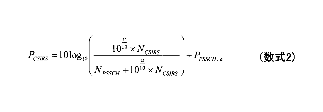

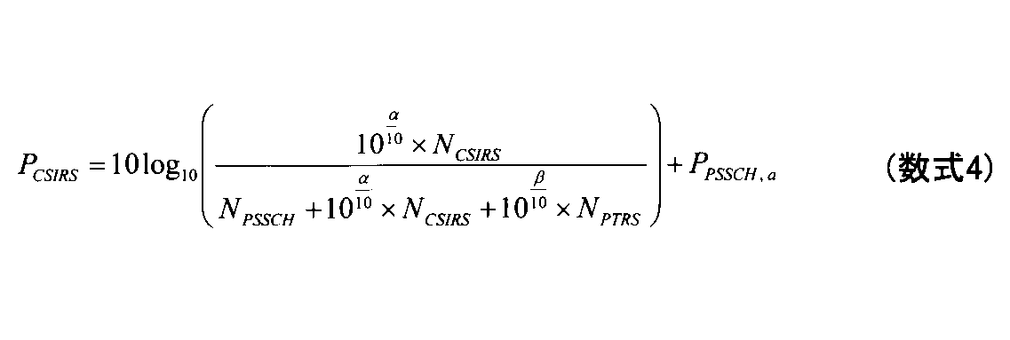
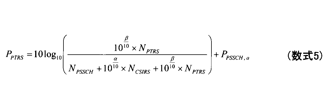
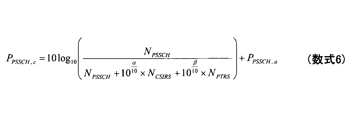
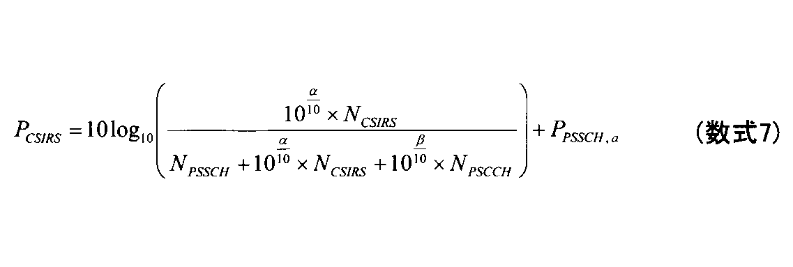

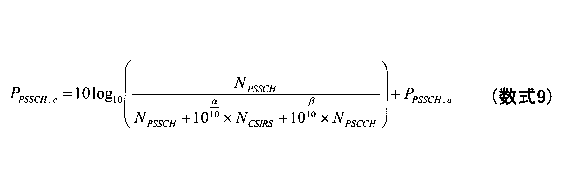
端末20が、CSI-RS及び/又はPT-RSの送信電力をブーストするか否か、及びCSI-RSの送信電力の増加量及び/又はPT-RSの送信電力の増加量(例えば、A1-1における数式内のαの値及び/又はβの値)は、仕様書により規定されてもよい。例えば、α=3、β=3であってもよい。端末20が、CSI-RS及び/又はPT-RSの送信電力をブーストするか否か、及びCSI-RSの送信電力の増加量及び/又はPT-RSの送信電力の増加量(例えば、A1-1における数式内のαの値及び/又はβの値)は、例えば、ネットワークにより(事前に)設定されてもよく、サイドリンクでのRRCシグナリングである他の端末20により送信されるPC5-RRCメッセージにより設定されてもよい。また、端末20が、CSI-RS及び/又はPT-RSの送信電力をブーストするか否か、及びCSI-RSの送信電力の増加量及び/又はPT-RSの送信電力の増加量(例えば、A1-1における数式内のαの値及び/又はβの値)は、例えば、スケジューリングを行うための、Downlink Control Information(DCI)及び/又はSidelink Control Information(SCI)により指定されてもよい。例えば、DCI/SCIにおいて、送信電力制御のための専用のフィールドが規定されてもよい。また、CSI-RSの存在/設定を示す他のフィールドが規定されてもよい。また、端末20が、CSI-RS及び/又はPT-RSの送信電力をブーストするか否か、及びCSI-RSの送信電力の増加量及び/又はPT-RSの送信電力の増加量(例えば、A1-1における数式内のαの値及び/又はβの値)は、例えば、CSI-RSの構成及び/又はPT-RSの構成に依存してもよく、追加的に又は代替的に、CSI-RSのリソース及び/又はPT-RSのリソースに依存してもよい。例えば、CSI-RS及び/又はPT-RSのリソースが少ない場合には、CSI-RS及び/又はPT-RSの送信電力をブーストし、CSI-RS及び/又はPT-RSのリソースが多い場合には、CSI-RS及び/又はPT-RSの送信電力は、PSSCHに割り当てられる送信電力と同じ値に設定されてもよい。また、CSI-RS及び/又はPT-RSの構成の中に送信電力をブーストするか否かを示す要素を含めてもよい。なお、これらの情報は、上位レイヤのパラメータ等に基づいて決定されてもよく、上位レイヤのパラメータとDCI及び/又はSCIとの組み合わせに基づいて決定されてもよい。
CSI-RSの送信電力を算出するための関数は、端末20の最大送信電力以外については、PSSCHに割り当てられる送信電力の値を考慮しない関数であってもよい。同様に、PT-RSの送信電力を算出するための関数は、端末20の最大送信電力以外については、PSSCHに割り当てられる送信電力の値を考慮しない関数であってもよい。この場合、CSI-RSの送信電力は、PSSCHに割り当てられる送信電力の値に対する比を用いて算出されるものではなくなる。同様に、PT-RSの送信電力は、PSSCHに割り当てられる送信電力の値に対する比を用いて算出されるものではなくなる。このように、オプションA1を適用することによって、CSI-RS及び/又はPT-RSをブーストすることにより、チャネル状態情報を取得する際の精度を向上させることが可能となり、RSRP測定の精度を向上させることが可能となり、かつ/又は位相雑音を補償する際の精度を向上させることが可能となる。
端末20は、PSSCHと関連付けられたCSI-RS及び/又はPT-RSの送信電力を、PSSCHの送信電力と必ず同じに設定してもよい。すなわち、PSSCHの合計の送信電力PPSSCHは、CSI-RSの送信電力及び/又はPT-RSの送信電力を含み、かつPSSCHデータのRE、CSI-RSのRE、及び/又はPT-RSのREの間で均等に分配されてもよい。この構成によれば、装置の実装が容易になり、かつ仕様の変更も少なくすることが可能となる。
NRのサイドリンクのグループキャスト通信に対して、サイドリンクのパスロスに基づいて開ループ送信電力制御を行ってもよい。
NRのサイドリンクのグループキャスト通信に対して、サイドリンクのパスロスに基づく開ループ送信電力制御を適用するか否かを選択するための条件が規定されてもよい。
NRのサイドリンクのグループキャスト通信において、グループ内の受信側の端末20全てのRSRPが送信側の端末20で使用可能な場合に、送信側の端末20は、サイドリンクのパスロスに基づく開ループ送信電力制御を適用してもよい。グループ内の受信側の端末20のうち、少なくとも1つの受信側の端末20のRSRPが送信側の端末20で使用できない場合には、送信側の端末20は、サイドリンクのパスロスに基づく開ループ送信電力制御を無効としてもよい。この場合、下りリンクのパスロスに基づく開ループ送信電力制御が適用されてもよい。
NRのサイドリンクのグループキャスト通信において、グループキャストのAcknowlegement(ACK)/Negative-Acknowledgement(NACK)フィードバックが有効とされている場合に、送信側の端末20は、サイドリンクのパスロスに基づく開ループ送信電力制御を適用してもよい。グループキャストのACK/NACKフィードバックが無効とされている場合には、送信側の端末20は、サイドリンクのパスロスに基づく開ループ送信電力制御を適用しなくてもよい。
1.トランスポートブロックの復号に成功した場合に、受信側の端末20はACKを送信し、トランスポートブロックの復号に失敗した場合に、受信側の端末20はNACKを送信する。
2.トランスポートブロックの復号に成功した場合には、受信側の端末20はACK及びNACKを送信せず、トランスポートブロックの復号に失敗した場合に、受信側の端末20はNACKを送信する。
NRのサイドリンクのグループキャスト通信において、グループ内の端末20の数に応じて、送信側の端末20装置は、サイドリンクのパスロスに基づく開ループ送信電力制御を適用するか否かを決定してもよい。例えば、グループ内の端末20の数が、閾値Xよりも小さい(又はX以下の)場合には、送信側の端末20装置は、サイドリンクのパスロスに基づく開ループ送信電力制御を適用してもよい。グループ内の端末20の数が閾値X以上である(又はXよりも大きい)場合には、送信側の端末20装置は、サイドリンクのパスロスに基づく開ループ送信電力制御を適用しなくてもよい。ここで、閾値Xは、仕様により規定されてもよく、ネットワークにより(事前に)設定されてもよく、サイドリンクでのRRCシグナリングである他の端末20により送信されるPC5-RRCメッセージにより設定されてもよく、リソースプールの設定に基づいて規定又は決定されてもよく、かつ/又は輻輳レベルに基づいて規定されてもよい。
3GPPの会合では、距離に関連する情報(例えば、距離及び/又はRSRP)に応じてHybrid Automatic Repeat Request(HARQ)フィードバックを行うか否かが定まる機能(distance-based HARQ)が検討されている。送信側の端末20に距離的に近い受信側の端末20は、HARQフィードバックを行う。送信側の端末20から距離的に遠い受信側の端末20に対しては、それ程高い信頼性が要求されないことが想定されるため、距離的に遠い受信側の端末20は、HARQフィードバックを行わなくてもよい。
NRのサイドリンクのグループキャスト通信において、range requirementを満たす受信側の端末20全てのRSRPが送信側の端末20で使用可能である場合には、送信側の端末20は、サイドリンクのパスロスに基づく開ループ送信電力制御を適用してもよい。上記以外の場合には、送信側の端末20は、サイドリンクのパスロスに基づく開ループ送信電力制御を適用しなくてもよい。なお、受信側の端末20のRSRPは、送信側の端末20が受信側の端末20からフィードバックされるRSRPを受信することにより使用可能とされてもよく、或いは送信側の端末20が受信側の端末20から送信されるRSを受信して送信側の端末20がRSRPを測定することにより使用可能とされてもよい。
上述のオプションB1からオプションB5のうち、少なくとも2つのオプションを組み合わせてもよい。例えば、オプションB1及びオプションB2の条件を満たす場合、送信側の端末20装置は、サイドリンクのパスロスに基づく開ループ送信電力制御を適用してもよい。それ以外の場合には、送信側の端末20装置は、サイドリンクのパスロスに基づく開ループ送信電力制御を適用しなくてもよい。代替的に、例えば、オプションB1又はオプションB2の条件を満たす場合、送信側の端末20装置は、サイドリンクのパスロスに基づく開ループ送信電力制御を適用してもよい。それ以外の場合には、送信側の端末20装置は、サイドリンクのパスロスに基づく開ループ送信電力制御を適用しなくてもよい。
NRのサイドリンクの通信において、サイドリンクのパスロスの測定を行う場合、当該パスロスの測定を行うためのリファレンス信号をどの信号にするのか規定してもよい。
(オプションC1)
NRのサイドリンクの通信において、サイドリンクのパスロスの測定を行うための参照信号として、サイドリンクのDM-RSだけが使用可能であってもよい。
NRのサイドリンクの通信において、サイドリンクのパスロスの測定を行うための参照信号として、サイドリンクのCSI-RSだけが使用可能であってもよい。
NRのサイドリンクの通信において、サイドリンクのパスロスの測定を行うための参照信号として、サイドリンクのDM-RSを使用することが可能であり、かつ追加的に、サイドリンクのCSI-RSが使用可能であってもよい。ここで、サイドリンクのCSI-RSの使用については、端末20の実装に依存してもよい。
NRのサイドリンクの通信において、サイドリンクのパスロスの測定を行うための参照信号として、サイドリンクのCSI-RSを使用することが可能であり、かつ追加的に、サイドリンクのDM-RSが使用可能であってもよい。ここで、サイドリンクのDM-RSの使用については、端末20の実装に依存してもよい。
PSSCHと関連付けられるサイドリンクのSSB、及び/又はサイドリンクのCSI-RS、及び/又はサイドリンクのDM-RSは、送信側の端末20から送信されるPSCCH/PSSCH/PSFCHのパスロスリファレンス信号(pathloss reference RS)として、及び/又は受信側の端末20から送信されるPSCCH/PSSCH/PSFCHのパスロスリファレンス信号(pathloss reference RS)として、仕様により規定されてもよく、ネットワークにより(事前に)設定されてもよく、サイドリンクでのRRCシグナリングである他の端末20により送信されるPC5-RRCメッセージにより設定されてもよい。
ブロードキャスト送信に対して使用されるDM-RS及び/又はCSI-RS、又はPC5-RRC接続が行われる前のサイドリンク送信に使用されるDM-RS及び/又はCSI-RSをパスロスリファレンス信号としてもよい。
受信される全てのDM-RS及び/又はCSI-RSをパスロスリファレンス信号としてもよい。オプションCiiの変形例として、例えば、特定の端末20から送信されるDM-RS及び/又はCSI-RSをパスロスリファレンス信号としてもよい。
サイドリンクチャネルに対して、TCI stateがネットワークにより(事前に)設定される場合、サイドリンクでのRRCシグナリングである他の端末20により送信されるPC5-RRCメッセージにより設定される場合、又は指定される場合、TCI stateに関連付けられるQCL type-A RS及び/又はQCL type-B RS及び/又はQCL type-C RS及び/又はQCL type-D RSをパスロスリファレンス信号としてもよい。図17は、TCI stateとリファレンス信号との対応の例を示す図である。
サイドリンクのパスロスに基づく開ループ送信電力制御を無効として、かつ/又は下りリンクの開ループ送信電力制御を有効としてもよい。
L1‐RSRP測定及び/又はL3‐RSRP測定のために規定されたDM-RS及び/又はCSI-RS、L1‐RSRP測定及び/又はL3‐RSRP測定のために(事前に)設定されたDM-RS及び/又はCSI-RS、又はL1‐RSRP測定及び/又はL3‐RSRP測定のためにPC5-RRCメッセージにより設定されたDM-RS及び/又はCSI-RSをパスロスリファレンス信号としてもよい。
複数のアンテナポートからそれぞれCSI-RSを送信する場合、例えば、2つのアンテナポートからCSI-RSを送信する場合、各CSI-RSの送信電力が2分の1となる場合が想定されている。この場合に、単純に電力を平均化することでRSRPを導出すると、2つのアンテナポートからCSI-RSが送信される場合には、それぞれのRSRPの値は2分の1となってしまう可能性がある。つまり、パスロスの計算を正確に行うことができなくなる可能性がある。従って、アンテナポートの数の設定等に応じて電力の正規化を行うことが必要になると想定される
端末20は、RSが単一のRSポートから送信される場合又はRSが単一のCDMグループから送信される場合にのみ、RSRPの測定を行ってもよい。
以下の電力正規化を行うことを前提として、端末20は、RSポートの数に関わらず、RSRPの測定を行ってもよい。
‐RSRPの計算では、RSポート数及び/又は各ポートからの送信電力を考慮する。
‐Case1:RSポートの数が複数であり、合計の送信電力が単一のRSポートの場合の送信電力と同じである場合、瞬時RSRP P1は、各RSポートからのRSRP、P2、P3、...の和をとることにより算出されてもよい。代替的に、1つのRSポートからのRSRP、P2、に対して、RSポート数を乗算することにより、瞬時PSPR P1が算出されてもよい。
‐Case2:RSポートの数が複数であり、合計の送信電力が単一のRSポートの場合の送信電力と異なり、かつ差分がZdBである場合、瞬時PSPR P1は、各RSポートからのRSRP、P2、P3、...の和からZdBを減算することで算出されてもよい。代替的に、1つのRSポートからのRSRP、P2に対して、RSポート数を乗算した上で、その結果からZdBを減算することで、瞬時PSPR P1が算出されてもよい。
リファレンス信号とPSSCHのデータとが周波数分割多重する場合にのみ、又はリファレンス信号とPSSCHのデータとが周波数分割多重されない場合にのみ、端末20は、RSRPの測定を行ってもよい。
端末20は、リファレンス信号とPSSCHのデータとが周波数分割多重されるか否かにかかわらず、RSRPの測定を行ってもよい。リファレンス信号とPSSCHのデータとが周波数分割多重される場合、端末20は、リファレンス信号がPSSCHのデータと周波数分割多重されない場合に基づいて、RSRPの補正を行ってもよい。代替的に、リファレンス信号がPSSCHのデータと周波数分割多重されない場合、端末20は、リファレンス信号がPSSCHのデータと周波数分割多重される場合に基づいて、RSRPの補正を行ってもよい。
図18は、送信側の端末20がL3-RSRP測定結果を取得するための2つの方法の例を示す図である。送信側の端末20は、受信側の端末20に対してPSSCHのデータ(例えば、トランスポートブロック及び/又はCSI)を伴うRSを送信し、受信側の端末20からRSRPフィードバックを取得することにより、L3-RSRPの測定結果を取得してもよい。代替的に、送信側の端末20は、受信側の端末20から送信されるPSCCHのデータ(例えば、トランスポートブロック及び/又はCSI)を伴うRSを受信し、受信したRSに基づきL3-RSRPを算出してもよい。このように、送信側の端末20では、受信側の端末20からフィードバックされるL3-RSRP測定結果に基づいて開ループ送信電力制御を行うことが可能であり、かつ送信側の端末20で算出したL3-RSRPに基づいて開ループ送信電力制御を行うことも可能である。このように、送信側の端末20において、フィードバックされるL3-RSRPと送信側の端末20自身で算出したL3-RSRPとの使い分けを規定してもよい。なお、以降では、フィードバックされるL3-RSRPは、フィードバックされる電力情報(例えば、L1-RSRP)に基づくL3-RSRPに置き換えられてもよい。
(オプションD1)
送信側の端末20は、受信側の端末20からフィードバックされるL3-RSRPと送信側の端末20自身で算出したL3-RSRPとの両方を使用してもよい。例えば、受信側の端末20からフィードバックされるL3-RSRP及び送信側の端末20自身で算出したL3-RSRPのうち、いずれか一方を優先して使用してもよい。
送信側の端末20は、受信側の端末20からフィードバックされるL3-RSRPだけを使用してもよい。この場合、送信側の端末20が、送信側の端末20自身で算出したL3-RSRPを、送信側の端末20自身の送信電力制御に使用することは想定されていなくともよい。
送信側の端末20は、送信側の端末20自身で算出したL3-RSRPだけを使用してもよい。この場合、受信側の端末20からフィードバックされるL3-RSRPは、開ループ送信電力制御以外の目的で報告されていると想定されてもよい。
仕様書において、上述のオプション1からオプション3までのうち、少なくとも2つのオプションを規定しておき、そのうちのいずれか1つのオプションをネットワークにより(事前に)設定してもよく、サイドリンクでのRRCシグナリングである他の端末20により送信されるPC5-RRCメッセージにより設定してもよく、ネットワークにより指定してもよい。
次に、これまでに説明した処理動作を実行する基地局10及び端末20の機能構成例を説明する。
図19は、基地局10の機能構成の一例を示す図である。図19に示されるように、基地局10は、送信部101と、受信部102と、制御部103とを有する。図19に示す機能構成は一例に過ぎない。本実施の形態に係る動作を実行できるのであれば、機能区分及び機能部の名称はどのようなものでもよい。なお、送信部101を送信機と称し、受信部102を受信機と称してもよい。
図20は、端末20の機能構成の一例を示す図である。図20に示されるように、端末20は、送信部201と、受信部202と、制御部203を有する。図20に示す機能構成は一例に過ぎない。本実施の形態に係る動作を実行できるのであれば、機能区分及び機能部の名称はどのようなものでもよい。なお、送信部201を送信機と称し、受信部202を受信機と称してもよい。また、端末20は、送信側の端末20Aであってもよいし、受信側の端末20Bであってもよい。さらに、端末20はスケジューリング端末20であってもよい。
上記実施の形態の説明に用いたブロック図(図19~図20)は、機能単位のブロックを示している。これらの機能ブロック(構成部)は、ハードウェア及びソフトウェアの少なくとも一方の任意の組み合わせによって実現される。また、各機能ブロックの実現方法は特に限定されない。すなわち、各機能ブロックは、物理的又は論理的に結合した1つの装置を用いて実現されてもよいし、物理的又は論理的に分離した2つ以上の装置を直接的又は間接的に(例えば、有線、無線などを用いて)接続し、これら複数の装置を用いて実現されてもよい。機能ブロックは、上記1つの装置又は上記複数の装置にソフトウェアを組み合わせて実現されてもよい。機能には、判断、決定、判定、計算、算出、処理、導出、調査、探索、確認、受信、送信、出力、アクセス、解決、選択、選定、確立、比較、想定、期待、見做し、報知(broadcasting)、通知(notifying)、通信(communicating)、転送(forwarding)、構成(configuring)、再構成(reconfiguring)、割り当て(allocating、mapping)、割り振り(assigning)などがあるが、これらに限られない。たとえば、送信を機能させる機能ブロック(構成部)は、送信部(transmitting unit)や送信機(transmitter)と呼称される。いずれも、上述したとおり、実現方法は特に限定されない。
本明細書には、少なくとも下記の端末及び通信方法が開示されている。
以上、本発明の実施の形態を説明してきたが、開示される発明はそのような実施形態に限定されず、当業者は様々な変形例、修正例、代替例、置換例等を理解するであろう。発明の理解を促すため具体的な数値例を用いて説明がなされたが、特に断りのない限り、それらの数値は単なる一例に過ぎず適切な如何なる値が使用されてもよい。上記の説明における項目の区分けは本発明に本質的ではなく、2以上の項目に記載された事項が必要に応じて組み合わせて使用されてよいし、ある項目に記載された事項が、別の項目に記載された事項に(矛盾しない限り)適用されてよい。機能ブロック図における機能部又は処理部の境界は必ずしも物理的な部品の境界に対応するとは限らない。複数の機能部の動作が物理的には1つの部品で行われてもよいし、あるいは1つの機能部の動作が物理的には複数の部品により行われてもよい。実施の形態で述べた処理手順については、矛盾の無い限り処理の順序を入れ替えてもよい。処理説明の便宜上、端末20と基地局10は機能的なブロック図を用いて説明されたが、そのような装置はハードウェアで、ソフトウェアで又はそれらの組み合わせで実現されてもよい。本発明の実施の形態に従って端末20が有するプロセッサにより動作するソフトウェア及び本発明の実施の形態に従って基地局10が有するプロセッサにより動作するソフトウェアはそれぞれ、ランダムアクセスメモリ(RAM)、フラッシュメモリ、読み取り専用メモリ(ROM)、EPROM、EEPROM、レジスタ、ハードディスク(HDD)、リムーバブルディスク、CD-ROM、データベース、サーバその他の適切な如何なる記憶媒体に保存されてもよい。
時間領域において1つ又は複数の各フレームはサブフレームと呼ばれてもよい。
サブフレームは更に時間領域において1つ又は複数のスロットによって構成されてもよい。サブフレームは、ニューメロロジー(numerology)に依存しない固定の時間長(例えば、1ms)であってもよい。
20 端末
101 送信部
102 受信部
103 制御部
201 送信部
202 受信部
203 制御部
1001 プロセッサ
1002 メモリ
1003 ストレージ
1004 通信装置
1005 入力装置
1006 出力装置
Claims (6)
-
サイドリンクのパスロスを測定するために使用可能なサイドリンクの参照信号として、規定された又は事前設定されたサイドリンクの参照信号を選択し、前記選択した参照信号を受信するための規定された又は事前設定されたポート又はインデックスを選択する制御部と、
前記制御部により選択された参照信号を受信する受信部と、
を備える端末。 - 前記サイドリンクのパスロスを測定するために使用可能なサイドリンクの参照信号は、サイドリンクの復調用参照信号、サイドリンクのチャネル状態情報推定用参照信号、及びサイドリンクのSynchronization Signal and Physical Broadcast Channel(SS/PBCH)ブロックのうちの少なくとも1つである、
請求項1に記載の端末。 - 前記制御部は、前記サイドリンクのパスロスを測定するために使用可能なサイドリンクの参照信号として、前記サイドリンクの復調用参照信号及び前記サイドリンクのチャネル状態情報推定用参照信号のうちのいずれか1つを選択し、かつ前記選択したサイドリンクの参照信号の全てのポート又はインデックスを前記サイドリンクのパスロスの測定のために選択する、
請求項2に記載の端末。 - 前記受信部は、前記制御部が選択した参照信号を前記規定された又は事前設定されたポート又はインデックスを適用して受信することにより、受信電力を測定し、前記制御部は、前記受信電力を用いて開ループ送信電力制御を行う、又は前記受信電力を他の端末に送信することを決定する、
請求項1に記載の端末。 - 前記受信部は、前記制御部が選択した参照信号を前記規定された又は事前設定されたポート又はインデックスを適用して受信し、前記規定された又は事前設定されたポート又はインデックスの数に応じた電力の正規化を行って受信電力を測定する、
請求項1に記載の端末。 - サイドリンクのパスロスを測定するために使用可能なサイドリンクの参照信号として、規定された又は事前設定されたサイドリンクの参照信号を選択し、前記選択した参照信号を受信するための規定された又は事前設定されたポート又はインデックスを選択するステップと、
前記選択された参照信号を受信するステップと、
を備える、端末による通信方法。
Priority Applications (6)
| Application Number | Priority Date | Filing Date | Title |
|---|---|---|---|
| MX2022000605A MX2022000605A (es) | 2019-07-22 | 2019-07-22 | Terminal y metodo de comunicacion. |
| EP19938305.0A EP4007444A4 (en) | 2019-07-22 | 2019-07-22 | TERMINAL AND COMMUNICATION METHOD |
| JP2021534440A JP7669612B2 (ja) | 2019-07-22 | 2019-07-22 | 端末、通信システム及び通信方法 |
| PCT/JP2019/028717 WO2021014548A1 (ja) | 2019-07-22 | 2019-07-22 | 端末及び通信方法 |
| CN201980098494.2A CN114128399B (zh) | 2019-07-22 | 2019-07-22 | 终端以及通信方法 |
| US17/628,058 US20220279451A1 (en) | 2019-07-22 | 2019-07-22 | Terminal and communication method |
Applications Claiming Priority (1)
| Application Number | Priority Date | Filing Date | Title |
|---|---|---|---|
| PCT/JP2019/028717 WO2021014548A1 (ja) | 2019-07-22 | 2019-07-22 | 端末及び通信方法 |
Publications (1)
| Publication Number | Publication Date |
|---|---|
| WO2021014548A1 true WO2021014548A1 (ja) | 2021-01-28 |
Family
ID=74193002
Family Applications (1)
| Application Number | Title | Priority Date | Filing Date |
|---|---|---|---|
| PCT/JP2019/028717 Ceased WO2021014548A1 (ja) | 2019-07-22 | 2019-07-22 | 端末及び通信方法 |
Country Status (6)
| Country | Link |
|---|---|
| US (1) | US20220279451A1 (ja) |
| EP (1) | EP4007444A4 (ja) |
| JP (1) | JP7669612B2 (ja) |
| CN (1) | CN114128399B (ja) |
| MX (1) | MX2022000605A (ja) |
| WO (1) | WO2021014548A1 (ja) |
Cited By (2)
| Publication number | Priority date | Publication date | Assignee | Title |
|---|---|---|---|---|
| JP2023543828A (ja) * | 2020-09-30 | 2023-10-18 | 維沃移動通信有限公司 | パワー制御方法、装置及び端末機器 |
| WO2024171409A1 (ja) * | 2023-02-16 | 2024-08-22 | 株式会社Nttドコモ | 端末及び通信方法 |
Families Citing this family (9)
| Publication number | Priority date | Publication date | Assignee | Title |
|---|---|---|---|---|
| CN114342423B (zh) * | 2019-09-05 | 2024-04-26 | 联想(新加坡)私人有限公司 | 确定用于侧链路传输的天线面板 |
| US12438649B2 (en) * | 2019-11-05 | 2025-10-07 | Qualcomm Incorporated | Sidelink identification for multi-path downlink retransmission |
| US11889541B2 (en) * | 2020-01-24 | 2024-01-30 | Qualcomm Incorporated | Superposition transmission of sidelink and uplink |
| EP4150822A4 (en) * | 2020-05-14 | 2024-04-10 | Apple Inc. | System and method for phase noise reduction in very high frequency spectrum |
| CN115987470B (zh) * | 2020-05-27 | 2025-06-17 | 华为技术有限公司 | 一种通信方法及装置 |
| US12206609B2 (en) * | 2020-09-18 | 2025-01-21 | Qualcomm Incorporated | Phase-tracking reference signal configuration in sidelink |
| US20220225283A1 (en) * | 2021-01-14 | 2022-07-14 | Apple Inc. | Systems and methods for enhancement on sidelink power control |
| US12213084B2 (en) * | 2022-04-25 | 2025-01-28 | Qualcomm Incorporated | Aperiodic tracking reference signal triggering mechanism to update tracking reference signal power |
| WO2024078908A1 (en) * | 2022-10-13 | 2024-04-18 | Sony Group Corporation | Methods for sidelink communication, related wireless devices and a related network node |
Family Cites Families (14)
| Publication number | Priority date | Publication date | Assignee | Title |
|---|---|---|---|---|
| CN102158302B (zh) * | 2010-02-11 | 2013-09-18 | 电信科学技术研究院 | 一种信息指示的方法及设备 |
| JP2013034111A (ja) * | 2011-08-02 | 2013-02-14 | Sharp Corp | 基地局、端末、通信システムおよび通信方法 |
| JP6641465B2 (ja) * | 2015-10-01 | 2020-02-05 | エルジー エレクトロニクス インコーポレイティド | D2d通信における参照信号送信方法及び端末 |
| CN108702244B (zh) * | 2016-04-01 | 2022-04-29 | 英特尔公司 | 用于低复杂度设备到设备(d2d)通信的链路适配 |
| CN107370556A (zh) * | 2016-05-12 | 2017-11-21 | 株式会社Ntt都科摩 | 信道质量反馈方法、用户终端、信道质量测量的控制方法及基站 |
| WO2017195488A1 (ja) * | 2016-05-12 | 2017-11-16 | 株式会社Nttドコモ | ユーザ装置及び測定方法 |
| JP2019149594A (ja) * | 2016-07-15 | 2019-09-05 | シャープ株式会社 | 端末装置および方法 |
| EP3500016A4 (en) * | 2016-08-10 | 2020-08-12 | NTT DoCoMo, Inc. | USER TERMINAL, AND WIRELESS COMMUNICATION PROCESS |
| CN108631975A (zh) * | 2017-03-23 | 2018-10-09 | 株式会社Ntt都科摩 | 参考信号发送方法、信道测量方法、无线基站及用户终端 |
| CN108631912B (zh) * | 2017-03-23 | 2021-09-28 | 大唐移动通信设备有限公司 | 一种传输方法和装置 |
| WO2019087371A1 (ja) * | 2017-11-02 | 2019-05-09 | 株式会社Nttドコモ | ユーザ装置、及び制御情報送信方法 |
| CN111670594A (zh) * | 2018-02-16 | 2020-09-15 | 松下电器(美国)知识产权公司 | 发送机及发送方法 |
| EP4017207B1 (en) * | 2018-06-14 | 2023-12-13 | LG Electronics Inc. | Method and apparatus for performing sidelink communication by ue in nr v2x |
| CN113994611B (zh) * | 2019-05-03 | 2024-03-01 | Lg电子株式会社 | 用于在nr v2x中确定rsrp的方法及装置 |
-
2019
- 2019-07-22 JP JP2021534440A patent/JP7669612B2/ja active Active
- 2019-07-22 US US17/628,058 patent/US20220279451A1/en active Pending
- 2019-07-22 WO PCT/JP2019/028717 patent/WO2021014548A1/ja not_active Ceased
- 2019-07-22 EP EP19938305.0A patent/EP4007444A4/en active Pending
- 2019-07-22 MX MX2022000605A patent/MX2022000605A/es unknown
- 2019-07-22 CN CN201980098494.2A patent/CN114128399B/zh active Active
Non-Patent Citations (7)
| Title |
|---|
| 3GPP TS 36.213, June 2018 (2018-06-01) |
| 3GPP TS 38.211, June 2019 (2019-06-01) |
| 3GPP TS 38.214, March 2019 (2019-03-01) |
| 3GPP TS 38.331, April 2019 (2019-04-01) |
| CATT: "Sidelink physical layer procedures in NR V2X", 3GPP TSG RAN WG1 MEETING #97, R1-1906319, 4 May 2019 (2019-05-04), pages 1 - 7, XP051708354 * |
| ERICSSON: "DMRS design for two-port PSSCH transmission", 3GPP TSG-RAN WG1 MEETING #92, R1-1802521, 16 February 2018 (2018-02-16), pages 1 - 8, XP051397315 * |
| QUALCOMM INCORPORATED: "Considerations on Physical Layer aspects of NR V2X", 3GPP TSG RAN WG1 MEETING #97, R1-1907269, 4 May 2019 (2019-05-04), pages 1 - 15, XP051709292 * |
Cited By (3)
| Publication number | Priority date | Publication date | Assignee | Title |
|---|---|---|---|---|
| JP2023543828A (ja) * | 2020-09-30 | 2023-10-18 | 維沃移動通信有限公司 | パワー制御方法、装置及び端末機器 |
| JP7575583B2 (ja) | 2020-09-30 | 2024-10-29 | 維沃移動通信有限公司 | パワー制御方法、装置及び端末機器 |
| WO2024171409A1 (ja) * | 2023-02-16 | 2024-08-22 | 株式会社Nttドコモ | 端末及び通信方法 |
Also Published As
| Publication number | Publication date |
|---|---|
| JP7669612B2 (ja) | 2025-04-30 |
| EP4007444A4 (en) | 2023-03-29 |
| CN114128399B (zh) | 2024-01-05 |
| MX2022000605A (es) | 2022-03-04 |
| JPWO2021014548A1 (ja) | 2021-01-28 |
| CN114128399A (zh) | 2022-03-01 |
| EP4007444A1 (en) | 2022-06-01 |
| US20220279451A1 (en) | 2022-09-01 |
Similar Documents
| Publication | Publication Date | Title |
|---|---|---|
| JP7533876B2 (ja) | 端末、通信システム及び通信方法 | |
| JP7669612B2 (ja) | 端末、通信システム及び通信方法 | |
| US12132684B2 (en) | Communication apparatus and channel state information measuring method | |
| JP7301196B2 (ja) | 端末、無線通信方法及びシステム | |
| US12279294B2 (en) | Uplink resource configuration | |
| JP7285317B2 (ja) | 通信装置、通信方法及び通信システム | |
| US20220232520A1 (en) | Terminal and communication method | |
| WO2019097646A1 (ja) | ユーザ端末及び無線通信方法 | |
| EP4030814B1 (en) | Terminal | |
| WO2018235248A1 (ja) | ユーザ端末及び無線通信方法 | |
| WO2018235270A1 (ja) | ユーザ端末及び無線通信方法 | |
| WO2022070284A1 (ja) | 端末、及びリソース制御方法 | |
| KR20220079835A (ko) | 단말 및 통신 방법 | |
| JP7230024B2 (ja) | 端末、無線通信方法、基地局及びシステム | |
| CN114731622A (zh) | 终端和通信方法 | |
| WO2021065013A1 (ja) | 端末及び通信方法 | |
| WO2021070309A1 (ja) | 無線通信ノード | |
| CN114128400B (zh) | 终端以及通信方法 | |
| WO2019225655A1 (ja) | ユーザ端末 | |
| CN114731596A (zh) | 终端和通信方法 | |
| WO2020084788A1 (ja) | ユーザ装置 | |
| WO2020152902A1 (ja) | 端末及びチャネル状態情報通知方法 |
Legal Events
| Date | Code | Title | Description |
|---|---|---|---|
| 121 | Ep: the epo has been informed by wipo that ep was designated in this application |
Ref document number: 19938305 Country of ref document: EP Kind code of ref document: A1 |
|
| ENP | Entry into the national phase |
Ref document number: 2021534440 Country of ref document: JP Kind code of ref document: A |
|
| WWE | Wipo information: entry into national phase |
Ref document number: MX/A/2022/000605 Country of ref document: MX |
|
| NENP | Non-entry into the national phase |
Ref country code: DE |
|
| ENP | Entry into the national phase |
Ref document number: 2019938305 Country of ref document: EP Effective date: 20220222 |
|
| WWP | Wipo information: published in national office |
Ref document number: MX/A/2022/000605 Country of ref document: MX |
|
| WWG | Wipo information: grant in national office |
Ref document number: MX/A/2022/000605 Country of ref document: MX |