WO2021015106A1 - 赤外線撮像レンズ - Google Patents
赤外線撮像レンズ Download PDFInfo
- Publication number
- WO2021015106A1 WO2021015106A1 PCT/JP2020/027759 JP2020027759W WO2021015106A1 WO 2021015106 A1 WO2021015106 A1 WO 2021015106A1 JP 2020027759 W JP2020027759 W JP 2020027759W WO 2021015106 A1 WO2021015106 A1 WO 2021015106A1
- Authority
- WO
- WIPO (PCT)
- Prior art keywords
- lens
- infrared imaging
- image plane
- imaging lens
- glass
- Prior art date
- Legal status (The legal status is an assumption and is not a legal conclusion. Google has not performed a legal analysis and makes no representation as to the accuracy of the status listed.)
- Ceased
Links
Images



Classifications
-
- G—PHYSICS
- G02—OPTICS
- G02B—OPTICAL ELEMENTS, SYSTEMS OR APPARATUS
- G02B13/00—Optical objectives specially designed for the purposes specified below
- G02B13/14—Optical objectives specially designed for the purposes specified below for use with infrared or ultraviolet radiation
-
- G—PHYSICS
- G02—OPTICS
- G02B—OPTICAL ELEMENTS, SYSTEMS OR APPARATUS
- G02B13/00—Optical objectives specially designed for the purposes specified below
- G02B13/001—Miniaturised objectives for electronic devices, e.g. portable telephones, webcams, PDAs, small digital cameras
- G02B13/008—Miniaturised objectives for electronic devices, e.g. portable telephones, webcams, PDAs, small digital cameras designed for infrared light
-
- G—PHYSICS
- G02—OPTICS
- G02B—OPTICAL ELEMENTS, SYSTEMS OR APPARATUS
- G02B13/00—Optical objectives specially designed for the purposes specified below
- G02B13/001—Miniaturised objectives for electronic devices, e.g. portable telephones, webcams, PDAs, small digital cameras
- G02B13/0015—Miniaturised objectives for electronic devices, e.g. portable telephones, webcams, PDAs, small digital cameras characterised by the lens design
- G02B13/002—Miniaturised objectives for electronic devices, e.g. portable telephones, webcams, PDAs, small digital cameras characterised by the lens design having at least one aspherical surface
- G02B13/004—Miniaturised objectives for electronic devices, e.g. portable telephones, webcams, PDAs, small digital cameras characterised by the lens design having at least one aspherical surface having four lenses
-
- G—PHYSICS
- G02—OPTICS
- G02B—OPTICAL ELEMENTS, SYSTEMS OR APPARATUS
- G02B13/00—Optical objectives specially designed for the purposes specified below
- G02B13/06—Panoramic objectives; So-called "sky lenses" including panoramic objectives having reflecting surfaces
-
- G—PHYSICS
- G02—OPTICS
- G02B—OPTICAL ELEMENTS, SYSTEMS OR APPARATUS
- G02B13/00—Optical objectives specially designed for the purposes specified below
- G02B13/18—Optical objectives specially designed for the purposes specified below with lenses having one or more non-spherical faces, e.g. for reducing geometrical aberration
-
- G—PHYSICS
- G02—OPTICS
- G02B—OPTICAL ELEMENTS, SYSTEMS OR APPARATUS
- G02B7/00—Mountings, adjusting means, or light-tight connections, for optical elements
- G02B7/02—Mountings, adjusting means, or light-tight connections, for optical elements for lenses
- G02B7/028—Mountings, adjusting means, or light-tight connections, for optical elements for lenses with means for compensating for changes in temperature or for controlling the temperature; thermal stabilisation
-
- G—PHYSICS
- G02—OPTICS
- G02B—OPTICAL ELEMENTS, SYSTEMS OR APPARATUS
- G02B9/00—Optical objectives characterised both by the number of the components and their arrangements according to their sign, i.e. + or -
- G02B9/34—Optical objectives characterised both by the number of the components and their arrangements according to their sign, i.e. + or - having four components only
Definitions
- the present invention relates to an infrared imaging lens.
- Infrared cameras that shoot subjects in the far infrared region, especially in the wavelength region of about 8 to 14 ⁇ m, which is suitable for biological detection, are applied to surveillance cameras, security cameras, and in-vehicle night vision.
- the infrared imaging lens applied to these infrared cameras is configured by using a lens made of a material having a relatively high transmittance in a wavelength region of 8 to 14 ⁇ m.
- Germanium (Ge), silicon (Si), zinc sulfide (ZnS), zinc selenide (ZnSe), and chalcogenide glass have been used as such materials.
- the conventional chalcogenide glass has a refractive index of less than 2.8 in the far infrared region, which is smaller than that of these crystalline materials.
- an infrared imaging lens with a wide angle of view which is particularly required for applications such as surveillance cameras and security cameras, can be used with low aberration or peripheral illumination. It was difficult to suppress the decrease and realize it.
- One aspect of the present invention focuses on the above-mentioned problems, and in spite of having a wide angle of view, infrared rays in a far-infrared region having low aberration or suppressed decrease in peripheral illumination and having excellent performance.
- the purpose is to realize an imaging lens.
- the infrared imaging lens includes a first lens having a negative refractive power and a meniscus convex on the image plane side in order from the object side to the image plane side.
- the second lens and the image plane side lens group having a positive refractive power are arranged, and the material of the first lens and the second lens has a refractive index of 2.8 or more at a wavelength of 10 ⁇ m. It is made of glass and has a structure in which a half angle of view is 60 ° or more.
- an infrared imaging lens in the far infrared region having excellent performance, which has low aberration or suppressed decrease in peripheral illumination despite having a wide angle of view.
- the infrared imaging lens 1 is a lens system that forms an image of a subject on an image plane S of an image sensor or the like, which corresponds to at least a wavelength region in the far infrared region.
- FIG. 1 is a cross-sectional view taken along the optical axis showing a schematic configuration of the infrared imaging lens 1.
- the outline of the infrared imaging lens 1 is as follows.
- the infrared imaging lens 1 is configured by arranging a first lens L1, a second lens L2, an aperture diaphragm A, and an image plane side lens group G in this order from the object side to the image plane side.
- a parallel flat plate P is arranged between the image plane side lens group G and the image plane S.
- the parallel flat plate P is an optical window loaded on the image plane side by hermetic sealing, and silicon, hypoxic silicon, or germanium is used. The material and thickness can be determined by which image sensor is used.
- the image plane side lens group G is composed of a third lens L3 and a fourth lens L4 in order from the object side to the image plane side.
- the first lens L1 to the fourth lens L4 move uniformly in the optical axis direction.
- Antireflection (AR) coating is applied to the surfaces of the first lens L1, the second lens L2, the third lens L3, the fourth lens L4, and the parallel flat plate P.
- Appropriate known techniques can be applied to the antireflection coating in such a far infrared region.
- the first lens L1 has a negative refractive power and has a meniscus shape with a convex surface facing the object side.
- the first lens L1 is an aspherical lens, the surface on the object side (first surface) is aspherical, and the surface on the image plane side (second surface) is spherical.
- the second lens L2 has a positive refractive power and has a meniscus shape with a convex surface facing the image plane side.
- the second lens L2 is an aspherical lens, its object-side surface (third surface) is aspherical, and its image plane-side surface (fourth surface) is aspherical.
- the refractive power of the second lens L2 can be negative or zero.
- the image plane side lens group G has a positive refractive power.
- the third lens L3 is a biconvex lens having a positive refractive power.
- the third lens L3 is an aspherical lens, the surface on the object side (sixth surface) is aspherical, and the surface on the image plane side (seventh surface) is spherical.
- the fourth lens L4 has a positive refractive power and has a meniscus shape with a convex surface facing the image plane side.
- the fourth lens L4 is an aspherical lens, its object-side surface (eighth surface) is spherical, and its image plane-side surface (nineth surface) is aspherical.
- the infrared imaging lens 1 has the following characteristic configurations, particularly in the first lens L1 and the second lens L2. With such a characteristic configuration, in the wavelength band in the far infrared region, although the half angle of view ⁇ is larger than 60 °, the occurrence of aberration and the decrease in the amount of peripheral light are suppressed, and the good imaging characteristics are suppressed. Is realized. Preferably, the half angle of view ⁇ is as high as 80 ° or more.
- the first lens L1 and the second lens L2 are made of a material made of glass having a refractive index of 2.8 or more at a wavelength of 10 ⁇ m and having light transmittance in a wavelength band of at least 8 to 14 ⁇ m in the far infrared region.
- the first lens L1 and the second lens L2 have a refractive index of 3 or more at a wavelength of 10 ⁇ m. More preferably, the first lens L1 and the second lens L2 have a refractive index of 3.3 or more at a wavelength of 10 ⁇ m.
- the materials of the first lens L1 and the second lens L2 are new glass having good light transmittance in the wavelength band in the far infrared region and a large refractive index, specifically chalcogenide. Glass is applied.
- Calcogenide glass having such characteristics was newly developed by the applicants.
- the method for producing the chalcogenide glass and the like will be described later.
- infrared absorption edge wavelength and “internal transmittance” can be used as indicators indicating that the light transmittance is excellent in the far infrared region.
- the infrared absorption edge wavelength means an absorption edge wavelength in a far infrared region having a wavelength of 8 ⁇ m or more, and is defined as a wavelength at which the light transmittance is 20% at a material thickness of 2 mm.
- the internal transmittance refers to the transmittance inside the material and does not include the reflection loss on the surface of the material.
- the infrared absorption edge wavelength of chalcogenide glass as a material constituting the first lens L1 and the second lens L2 is 20 ⁇ m or more. Therefore, the chalcogenide glass also transmits infrared rays having a wavelength exceeding 12 ⁇ m, and has good transmittance over at least a wavelength range of 8 to 14 ⁇ m.
- the internal transmittance of the chalcogenide glass at a thickness of 2 mm is 90% or more at a wavelength of 12 ⁇ m.
- the Abbe number of the chalcogenide glass is 180 to 300.
- the Abbe number of the chalcogenide glass is 200 to 290.
- a characteristic material having a relatively large Abbe number and easily reducing chromatic aberration is applied to the first lens L1 and the second lens L2.
- the definition of the Abbe number in the present specification is described in the numerical examples described later.
- the first lens L1 has a large refractive index of 2.8 or more and has a negative meniscus shape with a convex surface facing the object side, it is possible to collect light rays from the object side to a wide angle of view, and the half angle of view ⁇ is set.
- An infrared imaging lens with a wide angle of view of 60 ° or more can be realized.
- the half angle of view ⁇ can be 80 ° or more.
- the second lens L2 has a large refractive index of 2.8 or more, and has a positive meniscus shape with a convex surface facing the image plane side. Therefore, a light beam having a large incident angle (peripheral part of the image plane) can be spread outward (the effective diameter of the fourth surface is larger than the effective diameter of the third surface), and vignetting of the luminous flux at the peripheral image height is reduced. , It is possible to suppress a decrease in the amount of ambient light.
- the optical axis of the light beam incident on the third lens L3 is formed even though the half angle of view ⁇ is larger than 60 °.
- the angle from is narrowed to the range of the standard lens.
- the angle of the light ray incident on the third lens L3 from the optical axis can be up to about 40 °, and the occurrence of aberration can be suppressed as much as possible.
- the combined refractive power of the first lens L1 and the second lens L2 is configured to be negative or zero.
- the refractive index at a wavelength of 10 ⁇ m is less than 2.8, which is small. Therefore, with these materials, it has been difficult to realize an infrared imaging lens having a wide angle of view that sufficiently suppresses aberrations or suppresses a decrease in peripheral illumination.
- the first lens L1 and the second lens L2 are made of chalcogenide glass that can be press-molded, aspherical lenses can be produced with good mass productivity.
- the glass transition temperature of the first lens L1 and the second lens L2 is as low as 200 ° C. or less, and press molding is easier.
- the glass transition temperature is preferably 180 ° C. or lower.
- Aberrations are suppressed by using the first lens L1 and the second lens L2 as aspherical lenses. If an aspherical surface cannot be applied to these lenses, the lens configuration for suppressing aberration will be an increase in the number of lenses.
- Image side lens group An aperture diaphragm A as a fifth surface is provided between the second lens L2 and the image plane side lens group G. Therefore, the height of the light beam incident on the image plane side lens group G can be lowered, and coma aberration can be suppressed.
- the third lens L3 and the fourth lens L4 as specific examples in the first embodiment of the image plane side lens group G are also molded using the same chalcogenide glass as the first lens L1 and the second lens L2.
- the third lens L3 and the fourth lens L4 can also be aspherical lenses, aberrations are effectively suppressed.
- the image plane side lens group can be configured using Ge as a material, for example.
- the image plane side lens group G is composed of two spherical lenses, the aberration becomes larger than that of the numerical embodiment 1.
- Such a configuration may be used as long as it is an infrared image pickup lens corresponding to an image sensor having a pixel pitch larger than that of the numerical embodiment 1.
- the image plane side lens group G is composed of three or more lenses, the aberration can be improved, but the configuration becomes complicated and the cost becomes high.
- the image plane side lens group may be composed of one lens. In that case, the aberration becomes larger than that of the numerical embodiment 1.
- Such a configuration may be used as long as it is an infrared image pickup lens compatible with an image sensor having a pixel pitch larger than that of the numerical embodiment 1.
- Example 1 a numerical example of the infrared imaging lens 1 in Example 1 will be shown.
- the cross-sectional view of the infrared imaging lens according to the numerical embodiment 1 is as shown in FIG.
- the unit of length is (mm).
- the * (asterisk) after the face number indicates that it is an aspherical surface.
- the surface data, aspherical surface data, and various data are shown below.
- aspherical shape is as follows: h: Height from the optical axis
- R Radius of curvature of the apex
- k Conical constant
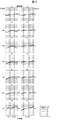
- FIG. 2 is an aberration diagram showing coma at each incident angle up to the maximum half angle of view of 91 °, divided into a tangential (meridional) direction and a sagittal (radical) direction.
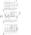
- FIG. 3 is an aberration diagram showing spherical aberration, astigmatism, and distortion. As shown in FIGS. 2 and 3, according to the infrared imaging lens according to the numerical embodiment 1, various aberrations are satisfactorily corrected.
- FIG. 4 is a graph showing the relationship of the peripheral illumination ratio to the incident angle of the infrared imaging lens of the numerical embodiment 1.
- the peripheral illumination ratio refers to the ratio of the illuminance in a certain region to the region on the optical axis (center region of the image plane) on the image plane.
- the peripheral illumination ratio at an incident angle of 91 ° is about 41%, which is sufficient.
- Peripheral illumination is obtained.
- the incident angle corresponding to the center of the left and right edges of the imaging surface is about 76 °.
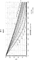
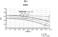
- FIG. 5 is a graph showing the spatial frequency dependence of the MTF (Modulation Transfer function). Further, FIG. 6 is a graph showing the incident angle dependence of the MTF. In FIGS. 5 to 7, the results in the tangier direction with respect to each incident angle are shown by solid lines, and the results in the sagittal direction are shown by broken lines.
- the Nyquist frequency of an image sensor with a pixel pitch of 17 ⁇ m, which is generally used for the far infrared region, corresponds to 29.4 cycles / mm. When the spatial frequency was 29.4 cycles / mm, the MTF at the center of the imaging surface (incident angle 0 °) was 48%.
- FIG. 7 is a graph showing the change in MTF with respect to focus movement.
- the chalcogenide glass contains tellurium (Te), which is a chalcogen element, as an essential component.
- Te is a component that forms a glass skeleton and enhances infrared transmittance.
- the content (molar fraction) of Te is 20 to 90%. It is preferably 30 to 88%, 40 to 84%, 50 to 82%, and particularly preferably 60 to 80%.
- Te selenium
- S sulfur
- the content of Se is preferably 0 to 40%, 0 to 20%, 0 to 10%, and 0 to 5%, and it is particularly preferable that the content is not substantially contained.
- the content of S is preferably 0 to 40%, 0 to 20%, 0 to 10%, and 0 to 5%, and it is particularly preferable that the content of S is substantially not contained.
- substantially not contained means that it is intentionally not contained in a raw material, and does not exclude contamination at an impurity level.
- the content of each component is preferably less than 0.1%.
- the contained components other than the above essential components are selected from the elements shown below, and are configured so that the content (mole fraction) of all the components of the chalcogenide glass is 100%.
- Germanium (Ge) is a component that expands the vitrification range and enhances the thermal stability of glass without lowering the infrared transmittance.
- the content of Ge is 0 to 50%. It is preferably 1 to 40%, 3 to 35%, 5 to 30%, 7 to 25%, and particularly preferably 10 to 20%. If the content of Ge is too large, Ge-based crystals tend to precipitate and the raw material cost tends to increase.
- Gallium (Ga) is a component that expands the vitrification range and enhances the thermal stability of glass without lowering the infrared transmittance.
- the content of Ga is 0 to 50%. It is preferably 1 to 30%, 2 to 20%, 3 to 15%, and particularly preferably 4 to 10%. If the content of Ga is too large, Ga-based crystals tend to precipitate and the raw material cost tends to increase.
- Silver (Ag) is a component that enhances the thermal stability of glass.
- the content of Ag is 0 to 50%. It is preferably more than 0 to 50%, 1 to 45%, 2 to 40%, 3 to 35%, 4 to 30%, 5 to 25%, and particularly preferably 5 to 20%. If the Ag content is too high, it becomes difficult to vitrify.
- the content of Al + Ti + Cu + In + Sn + Bi + Cr + Sb + Zn + Mn (the total amount of Al, Ti, Cu, In, Sn, Bi, Cr, Sb, Zn and Mn) is 0 to 40%. It is preferably 2 to 35%, 4 to 30%, and particularly preferably 5 to 25%.
- Al + Ti + Cu + In + Sn + Bi + Cr + Sb + Zn + Mn is too large, it becomes difficult to vitrify.
- Fluorine (F), chlorine (Cl), bromine (Br), and iodine (I) are also components that enhance the thermal stability of glass.
- the content of F + Cl + Br + I (the total amount of F, Cl, Br and I) is 0 to 40%. It is preferably 1 to 40%, 1 to 30%, 1 to 25%, and particularly preferably 1 to 20%.
- I is preferable in that an elemental raw material can be used and the effect of enhancing the thermal stability of glass is particularly large.
- Silicon (Si) is a component that enhances the thermal stability of glass.
- the Si content is 0 to 50%. It is preferably more than 0 to 50%, 1 to 45%, 2 to 40%, 3 to 35%, 4 to 30%, 5 to 25%, and particularly preferably 5 to 20%. If the content of Si is too large, infrared absorption due to Si is likely to occur, and it becomes difficult for infrared rays to pass through.
- the chalcogenide glass does not substantially contain cadmium (Cd), thallium (Tl) and lead (Pb).
- the chalcogenide glass applied to the infrared imaging lens 1 of the present embodiment is produced as follows. First, the raw materials are mixed so as to have the above glass composition to obtain a raw material batch. Next, after vacuum exhausting the quartz glass ampoule while heating it, a raw material batch is put in and the quartz glass ampoule is sealed with an oxygen burner. Oxygen gas (O 2 ) may not be present in the quartz glass ampoule, and may be replaced with, for example, an inert gas. As the inert gas, it is preferable to use nitrogen gas (N 2 ) because it is inexpensive and highly safe.
- the sealed quartz glass ampoule is heated to 650 to 1000 ° C. at a rate of 10 to 40 ° C./hour in a melting furnace, and then held for 6 to 12 hours. During the holding time, the quartz glass ampoule is turned upside down and the melt is agitated, if necessary.
- the chalcogenide glass applied to the infrared imaging lens 1 of the present embodiment has good infrared transmission characteristics because these phenomena are suppressed and produced. Further, in the chalcogenide glass applied to the infrared imaging lens 1 of the present embodiment, a high refractive index of 2.8 or more is realized in combination with the fact that the chalcogenide glass is uniformly configured with a specific composition.
- the quartz glass ampoule is taken out from the melting furnace and rapidly cooled to room temperature to produce chalcogenide glass.
- the quartz glass ampoule can be melted without being sealed, and the chalcogenide glass can be continuously melted. Further, the inert gas may be bubbled in the molten glass. Since the glass can be agitated by bubbling, the homogenization of the glass can be promoted. As a result, the occurrence of pulse and the like can be suppressed.
- the chalcogenide glass is put into the precision-processed mold and press-molded while heating until it becomes soft, and the surface shape of the mold is transferred to the chalcogenide glass. In this way, it is possible to manufacture a chalcogenide glass lens having a required shape to be applied to the infrared imaging lens 1.
- FIG. 8 shows the evaluation results of chalcogenide glass (sample numbers 1 to 24) produced by the above manufacturing process with various raw material ratios.
- FIG. 8 also shows the refractive index n10, the Abbe number ⁇ 10, and the infrared absorption edge wavelength.
- chalcogenide glasses have a refractive index of 2.8 or more at a wavelength of 10 ⁇ m. These have actually demonstrated the realization of chalcogenide glass with a refractive index in the range of 3.24 to 3.92 and an Abbe number in the range of 230 to 285.
- the infrared absorption edge wavelength of the chalcogenide glass was 24.1 ⁇ m or more, and the transmittance was good over at least the wavelength range of 8 to 14 ⁇ m.
- the internal transmittance of the chalcogenide glass at a thickness of 2 mm was 90% or more at a wavelength of 12 ⁇ m.
- the glass transition point of the chalcogenide glass was as small as 200 ° C. or less, and lens molding by press working was easy.
- the chalcogenide glass more preferably applied to the infrared imaging lens 1 of the present embodiment has a refractive index of 3.3 or more.
- a refractive index of 3.3 or more was obtained as a refractive index n10 at a wavelength of 10 ⁇ m.
- Each sample except sample number 23 is an example of chalcogenide glass more preferably applied to the infrared imaging lens 1 of the present embodiment.
- These have actually demonstrated the realization of chalcogenide glass with a refractive index in the range 3.32 to 3.92 and an Abbe number in the range 243 to 285.
- the required properties are at least in the range of Ge content of 3 to 45%, at least in the range of Ga content of 2 to 17.5%, and at least in the range of I content of 0 to 5%. It was demonstrated that (refractive index of 3.3 or more) can be obtained.
- the refractive index n10 at a wavelength of 10 ⁇ m was 2.585, which was less than 2.8.
- the novel chalcogenide glass applied to the present invention has a very large refractive index as compared with the conventional chalcogenide glass.
- the Abbe number is also appropriate. Therefore, a wide-angle infrared imaging lens 1 having good performance shown in FIGS. 2 to 7 has been realized.
- the infrared imaging lens according to the first aspect of the present invention includes a first lens having a negative refractive power, a second lens having a meniscus convex on the image plane side, and a positive lens in order from the object side to the image plane side.
- the image plane side lens group having a refractive power is arranged, and the material of the first lens and the second lens is glass having a refractive index of 2.8 or more at a wavelength of 10 ⁇ m and a half angle of view. It has a configuration that is 60 ° or more.
- the infrared imaging lens according to the second aspect of the present invention may have a configuration in which the glass is chalcogenide glass in the first aspect. According to the above configuration, an infrared imaging lens having good light transmission can be realized in a wavelength band of at least 8 to 14 ⁇ m.
- the infrared imaging lens according to the third aspect of the present invention may have a configuration in which the chalcogenide glass has a refractive index of 3.3 or more at a wavelength of 10 ⁇ m in the above aspect 2. According to the above configuration, the aberration can be suppressed better, or the decrease in the amount of peripheral light can be suppressed more.
- the infrared imaging lens according to the fourth aspect of the present invention has a configuration in which the chalcogenide glass has a thickness of 2 mm and an infrared absorption edge wavelength of 20 ⁇ m or more so that the light transmittance is 20% in the above aspects 2 or 3. You may. According to the above configuration, a bright infrared imaging lens having good light transmission can be realized in a wavelength band of at least 8 to 14 ⁇ m.
- the infrared imaging lens according to the fifth aspect of the present invention has a configuration in which the peripheral illumination ratio in the maximum angle-of-view region to the optical axis region on the image plane is 40% or more in any one of the above aspects 1 to 4. May be good. According to the above configuration, it is possible to realize an infrared imaging lens in the far infrared region in which a decrease in peripheral illumination is suppressed and good imaging characteristics are realized.
- the infrared imaging lens according to the sixth aspect of the present invention may have a configuration in which the first lens is a meniscus lens convex toward the object in any one of the above aspects 1 to 5. According to the above configuration, it is possible to realize an infrared imaging lens in the far infrared region in which aberrations are well suppressed despite a wide angle of view.
- the infrared imaging lens according to the seventh aspect of the present invention may have a configuration in which the first lens is an aspherical lens in any one of the above aspects 1 to 6. According to the above configuration, an infrared imaging lens in which aberrations are well suppressed can be realized with high productivity.
- the infrared imaging lens according to the eighth aspect of the present invention may have a configuration in which the second lens is an aspherical lens in any one of the above aspects 1 to 7. According to the above configuration, an infrared imaging lens in which aberrations are well suppressed can be realized with high productivity.
- the infrared imaging lens according to the ninth aspect of the present invention may have a configuration in which an aperture diaphragm is arranged between the second lens and the image plane side lens group in any one of the above aspects 1 to 8. .. According to the above configuration, the height of the light beam incident on the image plane side lens group can be lowered, and coma aberration can be suppressed.
- the infrared imaging lens according to the tenth aspect of the present invention is the third lens having a positive refractive power in any of the above aspects 1 to 9, in which the image plane side lens group has a positive refractive power in order from the object side to the image plane side. And a fourth lens having a positive refractive power may be provided. According to the above configuration, the image plane side lens group is realized more concretely.
- the infrared imaging lens according to the eleventh aspect of the present invention includes a first lens having a negative refractive power, a second lens having a meniscus convex on the image plane side, and a positive lens in order from the object side to the image plane side.
- a third lens having a refractive power and a fourth lens having a positive refractive power are arranged and configured, and the materials of the first lens, the second lens, the third lens, and the fourth lens are: It is a glass having a refractive power of 2.8 or more at a wavelength of 10 ⁇ m, and has a structure in which a half-angle is 60 ° or more.
- the image plane side lens group is realized more concretely, aberration is suppressed, and good imaging characteristics are realized in spite of a wide angle of view of 60 ° or more.
- An infrared imaging lens in the far infrared region can be realized.
- the infrared imaging lens according to the twelfth aspect of the present invention includes a first lens having a negative refractive power, a second lens having a meniscus convex on the image plane side, and a positive lens in order from the object side to the image plane side.
- the image plane side lens group having a refractive power is arranged, and the material of the first lens and the second lens is glass having a refractive index of 2.8 or more at a wavelength of 10 ⁇ m, and the first lens.
- the infrared imaging lens according to the thirteenth aspect of the present invention may have a configuration in which the glass transition temperature is 200 ° C. or less in any one of the above aspects 1 to 12. According to the above configuration, it is possible to realize an infrared imaging lens in the far infrared region, which can easily form a lens by press working, has excellent mass productivity, and can suppress aberrations due to aspherical formation.
Landscapes
- Physics & Mathematics (AREA)
- General Physics & Mathematics (AREA)
- Optics & Photonics (AREA)
- Health & Medical Sciences (AREA)
- Toxicology (AREA)
- Lenses (AREA)
- Glass Compositions (AREA)
Abstract
Description
実施例1に係る赤外線撮像レンズ1は、少なくとも遠赤外領域の波長領域に対応した、イメージセンサ等の像面Sに被写体の像を結像するレンズ系である。図1は、赤外線撮像レンズ1の概略構成を示す、光軸に沿った断面図である。
赤外線撮像レンズ1の概要は以下の通りである。赤外線撮像レンズ1は、物体側から像面側に向かって順に、第1レンズL1、第2レンズL2、開口絞りA、像面側レンズ群Gが配置されて構成される。図1に示されるように、像面側レンズ群Gと像面Sとの間には、平行平板Pが配置されている。平行平板Pは像面側にハーメチックシーリングで装荷される光学ウィンドーであり、シリコン、低酸素シリコンまたはゲルマニウムが使用される。材質や厚みは、どのイメージセンサを採用するかで決めることができる。
赤外線撮像レンズ1は、特に第1レンズL1及び第2レンズL2において以下の特徴的な構成を備えている。そのような特徴的な構成によって、遠赤外領域の波長帯において、半画角ωが60°よりも大きいにも係わらず、収差の発生と周辺光量の低下が抑制された良好な結像特性が実現される。好ましくは、半画角ωは80°以上にもなる。
第2レンズL2と像面側レンズ群Gとの間には、第5面としての開口絞りAが設けられる。そのため像面側レンズ群Gに入射する光線の高さを低くすることができ、コマ収差を抑制することができる。
次に、実施例1における赤外線撮像レンズ1の数値実施例を示す。数値実施例1に係る赤外線撮像レンズの断面図は、図1に示された通りである。数値実施例1において、rは曲率半径、dは光軸上の面間の距離、EDは有効径(直径)を表す。長さの単位は(mm)である。面番号の数字の後の*(アスタリスク)は非球面であることを表す。以下に、面データ、非球面データ、各種データを示す。
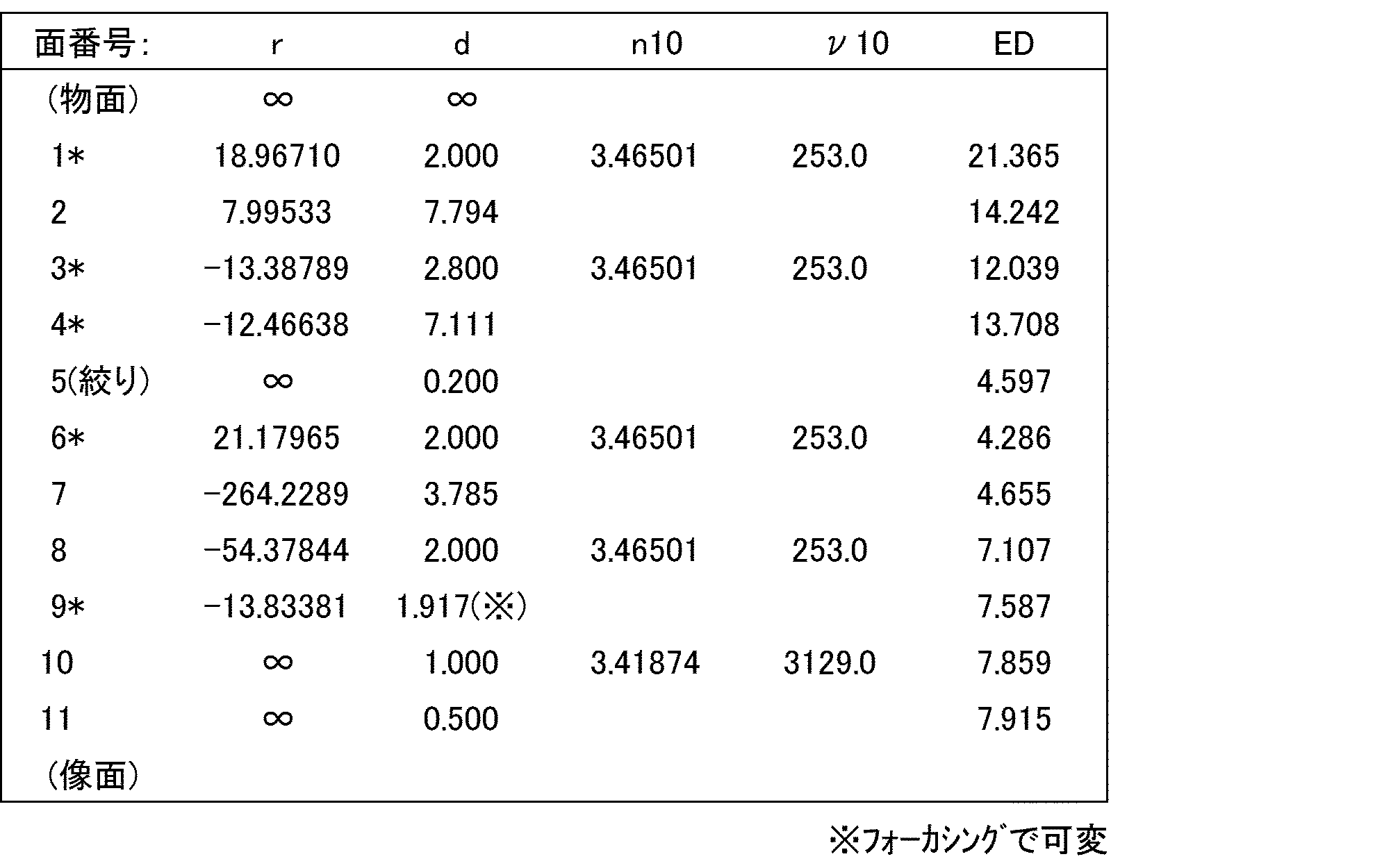
屈折率n8:波長8μmにおける屈折率
屈折率n10:波長10μmにおける屈折率
屈折率n12:波長12μmにおける屈折率
アッベ数ν10: ν10=(n10-1)/(n8-n12)
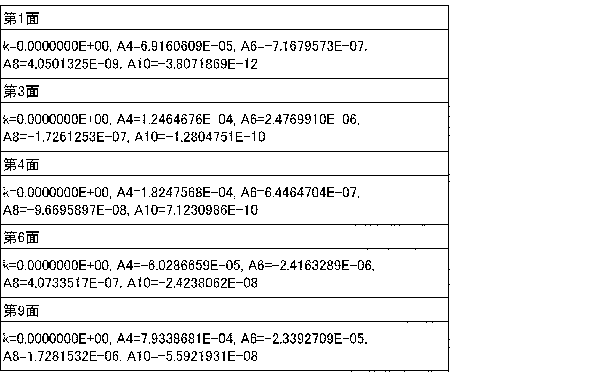

R:頂点曲率半径
k:円錐定数
An:n次の非曲面係数(n:4以上の偶数)
Z:hにおける非球面上の点から非球面頂点の接平面までの距離

次に、本実施形態の赤外線撮像レンズ1に適用されるカルコゲナイドガラスについて説明する。
本発明の態様1に係る赤外線撮像レンズは、物体側から像面側に向かって順に、負の屈折力を有する第1レンズと、像面側に凸のメニスカスである第2レンズと、正の屈折力を有する像面側レンズ群と、を配置して構成され、前記第1レンズ及び前記第2レンズの材料は、波長10μmにおける屈折率が2.8以上のガラスであり、半画角が60°以上である、構成を備えている。
L1 第1レンズ
L2 第2レンズ
A 開口絞り
G 像面側レンズ群
L3 第3レンズ
L4 第4レンズ
P 平行平板
S 像面
Claims (13)
- 物体側から像面側に向かって順に、
負の屈折力を有する第1レンズと、
像面側に凸のメニスカスである第2レンズと、
正の屈折力を有する像面側レンズ群と、を配置して構成され、
前記第1レンズ及び前記第2レンズの材料は、波長10μmにおける屈折率が2.8以上のガラスであり、
半画角が60°以上である、赤外線撮像レンズ。 - 前記ガラスが、カルコゲナイドガラスである、請求項1に記載の赤外線撮像レンズ。
- 前記カルコゲナイドガラスは、波長10μmにおける屈折率が3.3以上である、請求項2に記載の赤外線撮像レンズ。
- 前記カルコゲナイドガラスは、厚み2mmでの光透過率が20%となる赤外吸収端波長が20μm以上である、請求項2または3に記載の赤外線撮像レンズ。
- 像面において光軸上領域に対する最大画角領域での周辺光量比が40%以上である、請求項1から4のいずれか1項に記載の赤外線撮像レンズ。
- 前記第1レンズは物体側に凸のメニスカスレンズである、請求項1から5のいずれか1項に記載の赤外線撮像レンズ。
- 前記第1レンズは非球面レンズである、請求項1から6のいずれか1項に記載の赤外線撮像レンズ。
- 前記第2レンズは非球面レンズである、請求項1から7のいずれか1項に記載の赤外線撮像レンズ。
- 前記第2レンズと前記像面側レンズ群との間に開口絞りが配置される、請求項1から8のいずれか1項に記載の赤外線撮像レンズ。
- 前記像面側レンズ群は、物体側から像面側に向かって順に、正の屈折力を有する第3レンズと、正の屈折力を有する第4レンズと、を備える請求項1から9のいずれか1項に記載の赤外線撮像レンズ。
- 物体側から像面側に向かって順に、
負の屈折力を有する第1レンズと、
像面側に凸のメニスカスである第2レンズと、
正の屈折力を有する第3レンズと、
正の屈折力を有する第4レンズと、を配置して構成され、
前記第1レンズ、前記第2レンズ、前記第3レンズ及び前記第4レンズの材料は、波長10μmにおける屈折率が2.8以上のガラスであり、
半画角が60°以上である、赤外線撮像レンズ。 - 物体側から像面側に向かって順に、
負の屈折力を有する第1レンズと、
像面側に凸のメニスカスである第2レンズと、
正の屈折力を有する像面側レンズ群と、を配置して構成され、
前記第1レンズ及び前記第2レンズの材料は、波長10μmにおける屈折率が2.8以上のガラスであり、
前記第1レンズは物体側に凸のメニスカスレンズである、赤外線撮像レンズ。 - 前記ガラスは、ガラス転移温度が200℃以下である、請求項1から12のいずれか1項に記載の赤外線撮像レンズ。
Priority Applications (4)
| Application Number | Priority Date | Filing Date | Title |
|---|---|---|---|
| EP20844922.3A EP4006611A4 (en) | 2019-07-24 | 2020-07-17 | INFRARED IMAGE LENS |
| US17/626,930 US12360348B2 (en) | 2019-07-24 | 2020-07-17 | Infrared imaging lens |
| CN202080045155.0A CN113994248B (zh) | 2019-07-24 | 2020-07-17 | 红外线摄像镜头 |
| JP2021533994A JP7533462B2 (ja) | 2019-07-24 | 2020-07-17 | 赤外線撮像レンズ |
Applications Claiming Priority (2)
| Application Number | Priority Date | Filing Date | Title |
|---|---|---|---|
| JP2019-136421 | 2019-07-24 | ||
| JP2019136421 | 2019-07-24 |
Publications (1)
| Publication Number | Publication Date |
|---|---|
| WO2021015106A1 true WO2021015106A1 (ja) | 2021-01-28 |
Family
ID=74193615
Family Applications (1)
| Application Number | Title | Priority Date | Filing Date |
|---|---|---|---|
| PCT/JP2020/027759 Ceased WO2021015106A1 (ja) | 2019-07-24 | 2020-07-17 | 赤外線撮像レンズ |
Country Status (5)
| Country | Link |
|---|---|
| US (1) | US12360348B2 (ja) |
| EP (1) | EP4006611A4 (ja) |
| JP (1) | JP7533462B2 (ja) |
| CN (1) | CN113994248B (ja) |
| WO (1) | WO2021015106A1 (ja) |
Cited By (2)
| Publication number | Priority date | Publication date | Assignee | Title |
|---|---|---|---|---|
| CN113448063A (zh) * | 2021-05-21 | 2021-09-28 | 中国科学院西安光学精密机械研究所 | 一种大视场大相对孔径中波红外镜头 |
| WO2024135646A1 (ja) * | 2022-12-23 | 2024-06-27 | 日本電気硝子株式会社 | 赤外線撮像レンズ |
Families Citing this family (2)
| Publication number | Priority date | Publication date | Assignee | Title |
|---|---|---|---|---|
| US20240329368A1 (en) * | 2023-04-03 | 2024-10-03 | Raytheon Company | Optically athermal infrared reimaging lens assembly |
| CN119471992B (zh) * | 2023-08-08 | 2026-03-31 | 宁波舜宇红外技术有限公司 | 长波红外镜头 |
Citations (4)
| Publication number | Priority date | Publication date | Assignee | Title |
|---|---|---|---|---|
| US5446581A (en) * | 1993-03-15 | 1995-08-29 | Lockheed Missiles & Space Co., Inc. | Inverted telephoto wide-aperture wide-field infrared lens system |
| JP2013228539A (ja) * | 2012-04-25 | 2013-11-07 | Tamron Co Ltd | 赤外線用光学系 |
| WO2017094744A1 (ja) | 2015-12-03 | 2017-06-08 | 京セラオプテック株式会社 | 赤外線用結像レンズ |
| WO2018163831A1 (ja) | 2017-03-10 | 2018-09-13 | パナソニックIpマネジメント株式会社 | レンズ系、交換レンズ装置及びカメラシステム |
Family Cites Families (10)
| Publication number | Priority date | Publication date | Assignee | Title |
|---|---|---|---|---|
| GB0308025D0 (en) | 2003-04-07 | 2003-05-14 | Glaxo Group Ltd | Compounds |
| JP4841928B2 (ja) * | 2005-10-21 | 2011-12-21 | 富士フイルム株式会社 | 広角撮像レンズ |
| JP2012103461A (ja) * | 2010-11-10 | 2012-05-31 | Topcon Corp | 赤外線光学系 |
| JP5617642B2 (ja) * | 2011-01-06 | 2014-11-05 | ソニー株式会社 | 赤外線光学系、赤外線撮像装置 |
| TWI432821B (zh) * | 2011-01-20 | 2014-04-01 | Largan Precision Co | 攝影用光學透鏡組 |
| JP6405757B2 (ja) * | 2014-07-10 | 2018-10-17 | 株式会社タムロン | 遠赤外線レンズ及び遠赤外線撮像装置 |
| CN105044887B (zh) | 2015-06-02 | 2018-02-16 | 中国科学院上海技术物理研究所 | 一种制冷型大相对孔径超广角红外光学系统 |
| CN206479705U (zh) * | 2017-01-20 | 2017-09-08 | 宁波舜宇红外技术有限公司 | 一种红外鱼眼镜头 |
| IL271336B2 (en) * | 2017-06-20 | 2025-06-01 | Bae Sys Inf & Elect Sys Integ | Wide angle mwir f-theta lens |
| US10670841B2 (en) * | 2017-07-20 | 2020-06-02 | Raytheon Company | Two-color inverse telephoto refractive optical form with external pupil for cold shielding |
-
2020
- 2020-07-17 JP JP2021533994A patent/JP7533462B2/ja active Active
- 2020-07-17 CN CN202080045155.0A patent/CN113994248B/zh active Active
- 2020-07-17 EP EP20844922.3A patent/EP4006611A4/en active Pending
- 2020-07-17 WO PCT/JP2020/027759 patent/WO2021015106A1/ja not_active Ceased
- 2020-07-17 US US17/626,930 patent/US12360348B2/en active Active
Patent Citations (4)
| Publication number | Priority date | Publication date | Assignee | Title |
|---|---|---|---|---|
| US5446581A (en) * | 1993-03-15 | 1995-08-29 | Lockheed Missiles & Space Co., Inc. | Inverted telephoto wide-aperture wide-field infrared lens system |
| JP2013228539A (ja) * | 2012-04-25 | 2013-11-07 | Tamron Co Ltd | 赤外線用光学系 |
| WO2017094744A1 (ja) | 2015-12-03 | 2017-06-08 | 京セラオプテック株式会社 | 赤外線用結像レンズ |
| WO2018163831A1 (ja) | 2017-03-10 | 2018-09-13 | パナソニックIpマネジメント株式会社 | レンズ系、交換レンズ装置及びカメラシステム |
Non-Patent Citations (1)
| Title |
|---|
| See also references of EP4006611A4 |
Cited By (5)
| Publication number | Priority date | Publication date | Assignee | Title |
|---|---|---|---|---|
| CN113448063A (zh) * | 2021-05-21 | 2021-09-28 | 中国科学院西安光学精密机械研究所 | 一种大视场大相对孔径中波红外镜头 |
| CN113448063B (zh) * | 2021-05-21 | 2022-05-20 | 中国科学院西安光学精密机械研究所 | 一种大视场大相对孔径中波红外镜头 |
| WO2024135646A1 (ja) * | 2022-12-23 | 2024-06-27 | 日本電気硝子株式会社 | 赤外線撮像レンズ |
| JP2024090991A (ja) * | 2022-12-23 | 2024-07-04 | 日本電気硝子株式会社 | 赤外線撮像レンズ |
| JP7841422B2 (ja) | 2022-12-23 | 2026-04-07 | 日本電気硝子株式会社 | 赤外線撮像レンズ |
Also Published As
| Publication number | Publication date |
|---|---|
| JP7533462B2 (ja) | 2024-08-14 |
| CN113994248A (zh) | 2022-01-28 |
| JPWO2021015106A1 (ja) | 2021-01-28 |
| US20220276467A1 (en) | 2022-09-01 |
| EP4006611A4 (en) | 2023-08-30 |
| CN113994248B (zh) | 2024-11-08 |
| EP4006611A1 (en) | 2022-06-01 |
| US12360348B2 (en) | 2025-07-15 |
Similar Documents
| Publication | Publication Date | Title |
|---|---|---|
| CN104411649B (zh) | 校正透射近、中和远‑红外光谱的透镜的色差和热像差的玻璃 | |
| WO2021015106A1 (ja) | 赤外線撮像レンズ | |
| JP7495667B2 (ja) | カルコゲナイドガラスレンズ | |
| US7502175B2 (en) | Aspherical lens and process for the production thereof | |
| JP6069217B2 (ja) | 光学ガラス、プレス成形用ガラス素材、ならびに光学素子およびその製造方法 | |
| US11643357B2 (en) | Chalcogenide glass material | |
| JP7703936B2 (ja) | 赤外線撮像レンズ | |
| JP7719427B2 (ja) | 赤外線透過ガラス | |
| CN211123460U (zh) | 一种红外镜头 | |
| TWI703354B (zh) | 鏡頭模組及其近紅外線濾光片 | |
| JP7841422B2 (ja) | 赤外線撮像レンズ | |
| WO2023095900A1 (ja) | 赤外線透過ガラス | |
| JP2025045203A (ja) | 赤外線撮像レンズ | |
| WO2025100404A1 (ja) | 赤外線透過ガラス、光学素子及び赤外線カメラ | |
| CN121721812A (zh) | 一种长波连续变焦红外镜头及镜头模组 | |
| WO2023243407A1 (ja) | 赤外線透過ガラス | |
| CN118426149A (zh) | 一种长波双视场光学无热化镜头及其制作方法 |
Legal Events
| Date | Code | Title | Description |
|---|---|---|---|
| 121 | Ep: the epo has been informed by wipo that ep was designated in this application |
Ref document number: 20844922 Country of ref document: EP Kind code of ref document: A1 |
|
| ENP | Entry into the national phase |
Ref document number: 2021533994 Country of ref document: JP Kind code of ref document: A |
|
| NENP | Non-entry into the national phase |
Ref country code: DE |
|
| WWE | Wipo information: entry into national phase |
Ref document number: 2020844922 Country of ref document: EP |
|
| ENP | Entry into the national phase |
Ref document number: 2020844922 Country of ref document: EP Effective date: 20220224 |
|
| WWG | Wipo information: grant in national office |
Ref document number: 17626930 Country of ref document: US |