WO2021015134A1 - 材料設計システム、材料設計方法、及び材料設計プログラム - Google Patents
材料設計システム、材料設計方法、及び材料設計プログラム Download PDFInfo
- Publication number
- WO2021015134A1 WO2021015134A1 PCT/JP2020/027909 JP2020027909W WO2021015134A1 WO 2021015134 A1 WO2021015134 A1 WO 2021015134A1 JP 2020027909 W JP2020027909 W JP 2020027909W WO 2021015134 A1 WO2021015134 A1 WO 2021015134A1
- Authority
- WO
- WIPO (PCT)
- Prior art keywords
- design
- model
- interface
- learning
- condition
- Prior art date
- Legal status (The legal status is an assumption and is not a legal conclusion. Google has not performed a legal analysis and makes no representation as to the accuracy of the status listed.)
- Ceased
Links
Images


Classifications
-
- G—PHYSICS
- G06—COMPUTING OR CALCULATING; COUNTING
- G06F—ELECTRIC DIGITAL DATA PROCESSING
- G06F30/00—Computer-aided design [CAD]
- G06F30/20—Design optimisation, verification or simulation
-
- G—PHYSICS
- G06—COMPUTING OR CALCULATING; COUNTING
- G06F—ELECTRIC DIGITAL DATA PROCESSING
- G06F30/00—Computer-aided design [CAD]
- G06F30/10—Geometric CAD
-
- G—PHYSICS
- G06—COMPUTING OR CALCULATING; COUNTING
- G06F—ELECTRIC DIGITAL DATA PROCESSING
- G06F30/00—Computer-aided design [CAD]
- G06F30/20—Design optimisation, verification or simulation
- G06F30/27—Design optimisation, verification or simulation using machine learning, e.g. artificial intelligence, neural networks, support vector machines [SVM] or training a model
-
- G—PHYSICS
- G16—INFORMATION AND COMMUNICATION TECHNOLOGY [ICT] SPECIALLY ADAPTED FOR SPECIFIC APPLICATION FIELDS
- G16C—COMPUTATIONAL CHEMISTRY; CHEMOINFORMATICS; COMPUTATIONAL MATERIALS SCIENCE
- G16C60/00—Computational materials science, i.e. ICT specially adapted for investigating the physical or chemical properties of materials or phenomena associated with their design, synthesis, processing, characterisation or utilisation
-
- G—PHYSICS
- G06—COMPUTING OR CALCULATING; COUNTING
- G06F—ELECTRIC DIGITAL DATA PROCESSING
- G06F2111/00—Details relating to CAD techniques
- G06F2111/02—CAD in a network environment, e.g. collaborative CAD or distributed simulation
-
- G—PHYSICS
- G06—COMPUTING OR CALCULATING; COUNTING
- G06F—ELECTRIC DIGITAL DATA PROCESSING
- G06F2113/00—Details relating to the application field
- G06F2113/26—Composites
Definitions
- This disclosure relates to material design systems, material design methods, and material design programs.
- the trial production is repeated while adjusting the composition and manufacturing conditions of the material based on the experience of the material developer. Therefore, an optimum solution that can realize the desired material properties is obtained.
- trial production based on the experience of material developers often requires repeated trial production until the optimum design is obtained, which requires time and effort.
- the condition search is often performed locally in the vicinity of the design conditions performed by the material developer in the past, and is not suitable for the search for the global optimum design conditions.
- materials may be designed using simulation technology such as first-principles calculations.
- the sequential problem analysis is performed to predict the material properties under the conditions set by the simulation engineer.
- the result under the conditions set by the simulation engineer based on experience is output.
- simulation usually needs to be executed for a long time until the result is obtained, which is not suitable for short-time prediction or search for comprehensive material design.
- the purpose of this disclosure is to provide a material design system, a material design method, and a material design program that can utilize a wide range of high-quality machine learning learning results by utilizing the know-how of a small number of machine learning experts. To do.
- the present disclosure has the following configuration.
- a material design system for designing a material to be designed including a material having a plurality of compositions or a material manufactured by a combination of a plurality of manufacturing conditions.
- An expert terminal that can use an interface for model learning for performing machine learning of a model whose input / output is the correspondence between the design condition of the material to be designed and the material characteristic value.
- the material property value is obtained from the design condition, or the design is performed from the material property value, using the trained model for the specific design target material created by the expert terminal.
- Multiple general-purpose terminals that can use the material design interface for estimating conditions, Material design system with.
- An intermediate device for storing the trained model created by the expert terminal is provided.
- the plurality of general-purpose terminals use the trained model stored in the intermediate device to estimate the material property value from the design condition or the design condition from the material property value.
- the material design system according to [1].
- the model learning interface and the material design interface are mounted on a cloud server, and communication between the model learning interface and the material design interface is performed in the cloud server. Made by communication, The material design system according to [1] or [2].
- the model learning interface and the material design interface are installed in separate software compatible with each other.
- the material design system according to [1] or [2].
- the expert terminal is A learning condition setting unit that sets various conditions for machine learning of the model, A model learning unit that performs machine learning of the model based on the various conditions A model output unit that outputs the trained model and To prepare The material design system according to any one of [1] to [5].
- the general-purpose terminal is A design condition setting unit that sets a specified range of design conditions for the material to be designed, A comprehensive prediction point generation unit that generates a plurality of comprehensive prediction points within a specified range set by the design condition setting unit, Design condition-material characteristics for storing a data set in which the material characteristic values calculated by inputting the comprehensive prediction points generated by the comprehensive prediction point generator into the trained model are associated with each point of the comprehensive prediction points.
- Table and The required characteristic setting unit that sets the specified range of the required characteristics of the material to be designed, A design condition extraction unit that extracts a data set satisfying the required characteristics set by the required characteristic setting unit from the design condition-material characteristic table, and a design condition extraction unit.
- the general-purpose terminal is A design condition adjustment unit for adjusting the range of design conditions of the data set extracted by the design condition extraction unit is provided.
- the design condition extraction unit further narrows down the data set satisfying the design condition adjusted by the design condition adjustment unit from the extracted data set.
- a material design method for designing a material to be designed including a material having a plurality of compositions or a material manufactured by a combination of a plurality of manufacturing conditions.
- the material property value is obtained from the design condition, or the material property value is used as the material property value. Estimating steps to estimate design conditions and Material design method including.
- a material design program for designing a material to be designed including a material having a plurality of compositions or a material manufactured by a combination of a plurality of manufacturing conditions.
- a learning function that performs machine learning of a model that inputs and outputs the correspondence between the design conditions of the material to be designed and the material property values,
- the material property value is obtained from the design conditions, or the design is performed from the material property value.
- Estimating function to estimate the condition and A material design program for realizing a computer.
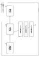
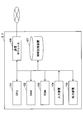
- FIG. 1 is a block diagram showing a schematic configuration of a material design system 1 according to an embodiment.
- the material design system 1 is an apparatus for designing a material to be designed including a material having a plurality of compositions or a material manufactured by a combination of a plurality of manufacturing conditions.
- the material design system 1 can be applied to the design of organic materials such as synthetic rubber, synthetic resin and synthetic elastomer, metal materials such as alloys and steel, and general materials such as inorganic materials and composite materials.
- the material to be designed by the material design system 1 depends on a material having a plurality of compositions or a combination of a plurality of manufacturing conditions / treatments (temperature, pressure, processing, oxidation treatment, acid treatment, compounding, mixing, stirring, etc.). Includes all materials manufactured.
- the material design system 1 includes a single expert terminal 2 and a plurality of (two in FIG. 1) general-purpose terminals 3.
- the expert terminal 2 is a device that can use the interface I1 for model learning.
- the model learning interface I1 is an interface for performing machine learning of a model whose input / output is the correspondence between the design condition of the material to be designed and the material property value.
- the model learning interface I1 is a GUI (graphical user interface) or an API (application programming interface) for using command programming.
- the model learning interface I1 of the expert terminal 2 is used by a machine learning expert such as a data scientist.
- the general-purpose terminal 3 is a device that can use the material design interface I2 for the specific design target material.
- the material design interface I2 estimates the material property value from the design condition or estimates the design condition from the material property value by using the trained model for the specific design target material created by the expert terminal 2. It is an interface to do.
- the material design interface I2 is a GUI with high user operability.
- the material design interface I2 of the general-purpose terminal 3 is used by a non-skilled person in machine learning such as a material designer, that is, a non-data scientist.
- the general-purpose terminal 3 is installed in each of a plurality of design departments in the company. At this time, the general-purpose terminal 3 does not have to be installed in all departments.
- two departments, department A and department B, are illustrated.
- materials A and B are designed as design target materials
- materials B and C are designed as design target materials. The case where it is done is illustrated.
- the expert terminal 2 creates a trained model using the model learning interface I1.
- the expert terminal 2 and the general-purpose terminal 3 are communicably connected, and the learned model is transmitted from the expert terminal 2 to each general-purpose terminal 3.
- the expert terminal 2 creates three types of trained models used for the materials A, B, and C of the material to be designed, and uses the trained model according to the material handled by each department as a general-purpose terminal of each department. Send to 3.
- the trained model for material A and the trained model for material B are transmitted to the general-purpose terminal 3 of department A that handles materials A and B, and the general-purpose terminal 3 of department B that handles materials B and C.
- the trained model for material B and the trained model for material C are transmitted to.
- the model learning interface I1 and the material design interface I2 which can operate independently, can be linked by a network connection or the like.
- the material design interface I2 is configured so that a non-data scientist material developer can design a material without performing machine learning.
- the interface I2 for material design has a highly versatile design regardless of the type of material, and by providing information by file transfer from the interface I1 for model learning, it is possible to develop all kinds of materials. It is configured to be applicable.
- the number of expert terminals 2 that can use the model learning interface I1 is smaller than that of the general-purpose terminals 3 that can use the material design interface I2, and each terminal 2 3 is another device.
- the material design system 1 according to the present embodiment can share the trained model created by the expert terminal 2 with many general-purpose terminals 3, so that the know-how of a small number of machine learning experts can be utilized.
- High-quality machine learning learning results can be used in multiple material design departments. That is, it is possible to obtain the effect that a wide range of high-quality machine learning learning results can be used.
- the material design system 1 of the present embodiment only secures a small number of data scientists by providing a small number of expert terminals 2 for the general-purpose terminal 3 as described above. Therefore, it is possible to deploy a system that efficiently supports material design to a large number of material development departments inside or outside the organization of a material manufacturer.
- the configuration in which the material design system 1 is installed in one company and the general-purpose terminals 3 are installed in each of a plurality of design departments in the company is illustrated, but the installation mode of the material design system 1 is this. Not limited to.
- one material design system 1 may be installed across a plurality of companies or organizations, and a general-purpose terminal 3 may be installed for each company or organization.
- the material design system 1 may be installed in one group, and a plurality of general-purpose terminals 3 may be installed in this group according to the application.
- FIG. 2 is a block diagram showing a modified example of the schematic configuration of the material design system 1 according to the embodiment.
- the material design system 1 may be configured to include an intermediate device 4 that stores a trained model created by the expert terminal 2.
- the plurality of general-purpose terminals 3 use the trained model stored in the intermediate device 4 to estimate the material property value from the design condition or the design condition from the material property value.
- each general-purpose terminal 3 can access and use the trained model stored in the intermediate device 4, so that each general-purpose terminal 3 uses the trained model. Therefore, it is not necessary to individually distribute the trained model data to each terminal, and machine learning can be performed more easily using the trained model. Further, since the availability of each general-purpose terminal 3 can be set by the access right to each trained model of the intermediate device 4, it is easy to manage the allocation of the trained models that can be used by each general-purpose terminal 3. it can.
- the communication between the expert terminal 2 and the general-purpose terminal 3, that is, the communication between the model learning interface I1 and the material design interface I2 can be realized in the following three forms, for example.
- the server (expert terminal 2) on which the model learning interface I1 is installed and the server (general-purpose terminal 3) on which the material design interface I2 is installed are connected by a network, and the model learning interface I1 Information such as learned models and name files (material names, material property names, design condition item names) can be transferred from the server of the material design interface I2 to the server of the material design interface I2.
- the trained model takes the format of pickle file, joblib file, etc.
- the name file takes the format of text file, CSV file, JSON file, XML file, etc.
- the above-mentioned method of providing information is not limited to file transfer, and may be a format for transferring information held in a recording medium such as a semiconductor memory such as a flash memory or a disk medium such as a DVD-ROM.
- Information may be transferred from the model learning interface I1 to the material design interface I2 directly from the model learning interface I1 server to the material design interface I2 server, as shown in FIG. Then, as shown in FIG. 2, after transferring from the model learning interface I1 to the intermediate server or directory (intermediate device 4), the material design interface I2 is allowed to access the intermediate device 4. You may.
- model learning interface I1 and the material design interface I2 are mounted on the cloud server, and the communication between the model learning interface I1 and the material design interface I2 is performed by communication in the cloud server. ..
- the model learning interface I1 and the material design interface I2 are separate interfaces installed in cloud servers such as AWS (registered trademark; Amazon Web Services) and GCP (registered trademark; Google Cloud Platform). Therefore, communication within the cloud server is secured. From the instance of the interface I1 for model learning in the cloud server to the instance of the interface I2 for material design, information about the trained model and name is transferred to a file, or a semiconductor memory such as a flash memory, a DVD-ROM, etc. It is transmitted in the form of transfer of information held in a recording medium such as disk media.
- Information transfer from the model learning interface I1 to the material design interface I2 may be performed directly from the instance of the model learning interface I1 to the instance of the material design interface I2, as shown in FIG. Then, as shown in FIG. 2, after transferring from the model learning interface I1 to the intermediate instance or the directory (intermediate device 4), the material design interface I2 is allowed to access the intermediate device 4. You may.
- the software of the interface I1 for model learning can output the trained model and the name file to the outside, and the software of the interface I2 for material design can read the trained model and the name file.
- the configuration in which the expert terminal 2 that can use the model learning interface I1 and the general-purpose terminal 3 that can use the material design interface I2 are separate devices has been illustrated.
- At least one of the expert terminal 2 and the general-purpose terminal 3 may be the same device. If a large number of material design interfaces I2 can be used for the model learning interface I1 even in a single device, the know-how of a small number of machine learning experts can be utilized for high-quality machine learning.
- the learning results can be used in multiple material design departments. That is, it is possible to obtain the effect that a wide range of high-quality machine learning learning results can be used.
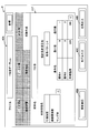
- FIG. 3 is a functional block diagram of the expert terminal 2.
- the expert terminal 2 includes a learning condition setting unit 41, a model learning unit 42, and a model transmission unit (model output unit) 43.
- the learning condition setting unit 41 sets various conditions for machine learning of the model.
- 4 to 9 are diagrams showing an example of input screens 41A to 41F of the learning condition setting unit 41 in the model learning interface I1.
- the input screen 41A is displayed as a tabbed window of "data visualization".
- the model learning interface I1 has a function of reading a data file such as a CSV format, and in FIG. 4, a data file "Y alloy data.csv" is selected and read in the file selection box 40A.
- a large number of sets of model input (design conditions) and model output (material property values) data sets related to Y alloy are recorded.
- the data set included in the read data file is displayed in a table, and the numerical values included in the data set are shown in a histogram, a scatter diagram, or the like.
- the input screen 41B is displayed as a tabbed window of "data division". On the input screen 41B, it is possible to input numerical values of various conditions (ratio of test data, random seed, etc.) on how to divide the data set included in the read data file into training data and test data. ..
- the input screen 41C is displayed as a tabbed window of "preprocessing".
- the settings for converting and normalizing the variables included in the data set using functions and the like, and the dimensions of the variables included in the data set are, for example, principal component analysis (PCA (principal component analysis)). It is possible to input settings for compression using, settings for assigning variables included in the dataset to the objective variables of the model, and explanatory variables.
- PCA principal component analysis
- the "+" button 41C1 is displayed in the item field of variable conversion. For example, by pressing the "+" button 41C1, an entry field such as a method can be added. ..
- the input screen 41D is displayed as a tabbed window of "machine learning”. On the input screen 41D, it is possible to input the selection of the machine learning method and the setting of hyperparameter tuning.
- "(100, 1000, 100)" is entered as the range of the hyper-tuning parameter, but these numerical values are (minimum, maximum, step size) of the range of the hyper-tuning parameter. Is shown.
- the input screen 41E is displayed as a tabbed window of "accuracy verification".
- a function setting for evaluating the prediction accuracy of the trained model by cross-validation a function setting for evaluating the prediction accuracy of the trained model using test data, and a prediction result by the trained model are shown. It is possible to enter the setting of the function to be performed.
- the input screen 41F is displayed as a "name creation" tabbed window.
- the trained model is output to the outside after designating the model name and the material name.
- material names, material property names, and design condition item names can be input, and settings for outputting them to the outside in the form of text files, CSV files, JSON files, XML files, etc. can be input. It has become.
- Each name of the material property name and the design condition item name can be manually input, or the name described in the read data file may be mechanically reflected.
- the material property name file and design condition item name file are linked to the material name. In the material property name file and the design condition item name file, only each name of the material property name and the design condition item name may be input, or the default value of the range of possible values may be input.
- the input screens 41A to 41F may be switched by tabs as shown in FIGS. 4 to 9, and analysis is performed using icons corresponding to the functions provided in the input screens 41A to 41F and arrows connecting the icons.
- a flow may be configured and learning conditions may be set according to the analysis flow.
- the model learning unit 42 performs machine learning of the model based on various conditions set by the learning condition setting unit 41.
- machine learning of the model is performed under the learning conditions set in FIGS. 4 to 8.
- machine learning is performed on the "model for material A”, the "model for material B”, and the “model for material C” assigned to the materials A, B, and C of the design target material, respectively.
- the trained models used for the design of materials A, B, and C are individually created.
- model learning unit 42 machine learning such as regression and classification can be performed, and the methods include linear, generalized linear (Lasso, Ridge, elastic net, logistic), kernel ridge, Bayesridge, Gaussian process, and so on. K-nearest neighbor method, decision tree, random forest, adder boost, bagging, gradient boosting, support vector machine, neural network, deep learning, etc. can be used.
- the model transmission unit 43 outputs the trained model. After designating the model name and material name, the trained model is output to the outside by pressing the "model output" button 40C of the model learning interface I1. Further, by pressing the "name output” button 40D, a name file including various names (material name, material property name, design condition item name) set in FIG. 9 is output to the outside.
- the expert terminal 2 outputs a learning condition setting unit 41 that sets various conditions for machine learning of the model, a model learning unit 42 that performs machine learning of the model based on various conditions, and a model that outputs the trained model 13.
- a transmission unit 43 is provided. This makes it possible to finely adjust various conditions for machine learning of the model, so that machine learning suitable for various uses can be performed. Further, the expert terminal 2 is particularly effective when used by a machine learning expert such as a data scientist, because more appropriate condition setting can be expected based on the knowledge of the expert.
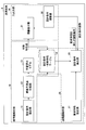
- FIG. 10 is a functional block diagram of the general-purpose terminal 3.
- the general-purpose terminal 3 includes a forward problem analysis unit 10, an inverse problem analysis unit 20, and an input / output unit 30.
- the forward problem analysis unit 10 uses the trained model 13 to output material properties that satisfy the design conditions desired by the material designer.
- the inverse problem analysis unit 20 outputs the design conditions satisfying the desired characteristics required by the material designer by using the design condition-material property table 14 created based on the output result of the forward problem analysis unit 10.
- the input / output unit 30 displays the output results of the forward problem analysis unit 10 and the inverse problem analysis unit 20 and presents them to the material designer, and accepts the adjustment operation of the output results by the material designer.
- the forward problem analysis unit 10 has a design condition setting unit 11, a comprehensive prediction point generation unit 12, a trained model 13, and a design condition-material property table 14.
- the design condition setting unit 11 sets a designated range of design conditions for the material to be designed. For example, the design condition setting unit 11 displays a design condition input screen on the material design interface I2 and prompts the material designer to input the type of the design target material and the specified range of the design condition.
- the specified range of design conditions can be set.
- FIG. 11 is a diagram showing an example of the input screen 11A of the design condition setting unit 11 in the material design interface I2.
- the input screen 11A is displayed as a tabbed window of "design conditions".
- a pull-down list 10A for selecting a material name to be designed is displayed, and in FIG. 11, "Y alloy" is selected as the material to be designed.
- the design condition setting unit 11 can read the name file described with reference to FIG. 9 and create a pull-down list 10A of selectable material names. Further, the design condition setting unit 11 reads the trained model associated with the selected material name.
- the design conditions include items related to the composition of raw materials (“raw material A” and “raw material B” in FIG. 11) and items related to manufacturing conditions (“processing temperature” in FIG. 11).
- the condition pattern can be selected from the pull-down menu.
- the design condition setting unit 11 reads the name file described with reference to FIG. 9 and creates a pull-down menu of selectable condition patterns. The items that can be selected as the condition pattern are determined by being associated with the material name.
- the materials of raw material composition for example, when the material to be designed is an aluminum (Al) alloy, Si, Fe, Cu, Mn, Mg, Cr, Ni, Zn, Ti, Na, V, Pb, Sn, B, Bi , Zr, O and other elemental species are included as additives in a mass percentage (mass%).
- the mass percentage of Al is represented by 100%-(the sum of the mass percentages of the above elements).
- the items related to heat treatment include annealing, solution treatment, artificial aging hardening treatment, natural aging treatment, hot working treatment, cold working treatment, and stabilizing treatment.
- the items related to the processing conditions include the temperature (° C.) and the implementation time (h) of each treatment such as, and include the processing rate, pressing ratio, surface reduction rate, product shape, and the like.
- the process of the forward problem analysis unit 10 is started by pressing the "analysis execution" button 10B of the material design interface I2.
- the coverage prediction point generation unit 12 generates a plurality of coverage prediction points within the specified range of the design conditions set by the design condition setting unit 11. For example, when the Si mass percentage of the composition item and the range of the annealing implementation time of the manufacturing condition item are specified, first, the specified range of the Si mass percentage and the specified range of the annealing implementation time are randomly or respectively. A plurality of numerical values are calculated with a predetermined step size, and all combinations of the plurality of numerical values of each item are created. These combinations are output as comprehensive prediction points.
- the trained model 13 has already acquired and formulated the correspondence between the input information including the design conditions of the material to be designed and the output information including the material property values by machine learning.
- the trained model 13 in the example of FIG. 11, the trained model used when the design target material is “Y alloy” is created by the expert terminal 2, and the general-purpose terminal 3 can be used.
- Items of material properties include tensile strength, 0.2% strength, elongation, linear expansion coefficient, Young's modulus, Poisson ratio, fatigue properties, hardness, creep properties including creep strength and creep strain, shear strength, specific heat, and heat. Includes conductivity, electrical resistance, density, solid phase, liquid phase, etc.
- FIG. 12 is a diagram showing an example of the output screen 31A of the forward problem analysis unit 10 in the material design interface I2.
- this output screen 31A is displayed as a tabbed window of "result (material property)".
- the output screen 31A is displayed on the material design interface I2 via, for example, the information display unit 31.
- the output (material property) of the trained model 13 is limited to only three, “tensile strength”, “coefficient of linear expansion”, and “Young's modulus” for the sake of simplification of explanation. Absent.
- the range of values of each material property is displayed by a box plot.
- the design condition-material property table 14 is a data set in which the material characteristic values calculated by inputting the comprehensive prediction points generated by the comprehensive prediction point generation unit 12 into the trained model 13 are associated with each point of the comprehensive prediction points.
- the forward problem analysis unit 10 calculates the coverage prediction point by the trained model 13
- the output is associated with the coverage prediction point (input) and stored in the design condition-material property table 14.
- the input (manufacturing condition, material composition) and output (material property) of the trained model are collected as one data set and recorded in the same row of the design condition-material property table 14. Will be done.
- Each row of the design condition-material property table 14 is an individual data set, and each column records the numerical value of each item of the input and output of the trained model 13.
- the design condition-material property table 14 is stored in association with the material name selected on the input screen 11A of FIG.
- the forward problem analysis unit 10 has the design conditions and material properties that cover the entire range of the multidimensional design conditions only by the material designer performing an operation of designating the range of the multidimensional design conditions. It is configured so that datasets can be automatically generated.
- the inverse problem analysis unit 20 has a required characteristic setting unit 21 and a design condition extraction unit 22.
- the above-mentioned design condition-material property table 14 is also included in the inverse problem analysis unit 20.
- the required characteristic setting unit 21 sets a designated range of required characteristics of the material to be designed.
- the required characteristic setting unit 21 can set the specified range of the required characteristic by displaying the input screen of the required characteristic on the material design interface I2 and prompting the material designer to input the specified range, for example.
- FIG. 13 is a diagram showing an example of the input screen 21A of the required characteristic setting unit 21.
- the input screen 21A is displayed as a tabbed window of "required characteristics".
- a pull-down list 10A for selecting a material name to be designed is displayed, and in FIG. 13, “Y alloy” is selected as the material to be designed.
- the required characteristic setting unit 21 can read the name file described with reference to FIG. 9 and create a pull-down list 10A of selectable material names. Further, the required characteristic setting unit 21 reads the design condition-material characteristic table 14 associated with the selected material name.
- the required property items are the same as the material property items described above.
- the characteristic name can be selected from the pull-down menu.
- the design condition setting unit 11 reads the name file described with reference to FIG. 9 and creates a pull-down menu of selectable characteristic names. Items that can be selected as characteristic names are determined in association with the material name. In the example of FIG. 13, "tensile strength", “linear expansion coefficient” and "Young's modulus” are selected as the required characteristics. Further, on the input screen 21A, the maximum value and the minimum value of each characteristic can be input.
- the process of the inverse problem analysis unit 20 is started by pressing the "analysis execution" button 10B of the material design interface I2.
- the design condition extraction unit 22 extracts a data set satisfying the required characteristics set by the required characteristic setting unit 21 from the design condition-material characteristic table 14.
- FIG. 14 is a diagram showing an example of the output screen 31B of the inverse problem analysis unit 20.
- this output screen 31B is displayed as a tabbed window of "result (design condition)".
- the output screen 31B is displayed on the material design interface I2 via, for example, the information display unit 31.
- the range of values of the composition (raw material A, raw material B) and the production condition (processing temperature) satisfying all the required characteristics set in FIG. 13 is displayed by a box plot.
- the window with the tab of "Result (material property)" described above is switched, the range of the value of each material property is updated and displayed to the range of the value of each material property corresponding to the design condition shown in FIG. Will be done.
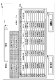
- FIG. 15 is a diagram showing an output screen 31C which is another example of the output screen of the inverse problem analysis unit 20.
- this output screen 31C is displayed as a tabbed window of "result (table)".
- the output screen 31C is displayed on the material design interface I2 via, for example, the information display unit 31.
- the required characteristics tensile strength, coefficient of linear expansion, Young's modulus
- the design conditions raw material A, raw material B, processing
- a table is displayed in which each value of (temperature) is summarized. Further, this table may be in a mode in which the display portion of the table can be moved by the scroll bar.
- the table shown in FIG. 15 can be output to the outside in a format such as a CSV file.
- the inverse problem analysis unit 20 extracts design conditions (material composition or manufacturing conditions) that simultaneously satisfy the multidimensional required characteristics simply by the material designer performing an operation of specifying a range of the multidimensional required characteristics. It is configured so that it can be done. Further, since the design condition-material property table 14 created by the forward problem analysis unit 10 is diverted without using a simulation or a learning model for the inverse problem analysis, the calculation cost can be significantly reduced.
- the input / output unit 30 has an information display unit 31.
- the information display unit 31 displays the output of the forward problem analysis unit 10 and the inverse problem analysis unit 20. For example, as shown in FIGS. 14 and 15, the required characteristics and the range of design conditions related to the data set extracted by the design condition extraction unit 22 are displayed.
- the input / output unit 30 may further include a design condition adjusting unit 32.
- the design condition adjustment unit 32 adjusts the range of design conditions of the data set extracted by the design condition extraction unit 22.
- the design condition adjusting unit 32 can adjust the range of the design condition by, for example, the operation input of the material designer who changes the composition range of the output screen 31B displayed on the material design interface I2.
- the design condition extraction unit 22 can further narrow down the data set group extracted according to the required characteristics to the data set group that satisfies the design condition adjusted by the design condition adjustment unit 32 described above.
- the inverse problem analysis unit 20 outputs design conditions that satisfy the required characteristics, but these design conditions are automatically extracted from the comprehensive prediction points of the design conditions-material property table 14, and the actual manufacturing difficulty is difficult. Manufacturing constraints such as degree are not taken into account. For example, it is difficult to handle and actually make, it takes a long time to make, it takes time to process, the composition that nests when casting, it can not be molded, it can be manufactured if cost is not considered, but with ordinary factory equipment There are various manufacturing restrictions such as not being able to make it.
- the output result of the inverse problem analysis unit 20 can be adjusted by the material designer using the design condition adjusting unit 32, so that the manufacturing conditions satisfying the required characteristics can be obtained. , It can be narrowed down in consideration of manufacturing restrictions based on the empirical rules of material designers. In other words, it is possible to design materials in which prediction by machine learning and the experience of material designers collaborate.
- the data set group used in the inverse problem analysis is created and stored in the design condition-material property table 14. Then, when performing the inverse problem analysis, a data set satisfying the required characteristics is extracted with reference to the design condition-material property table 14.
- the calculation cost can be significantly reduced and the desired material properties are satisfied because only the work of searching the design condition-material property table 14 is performed without performing any numerical calculation such as simulation or model calculation.
- the optimum solution of the design conditions can be derived in a short time.
- the search for candidate materials can be collectively performed so as to satisfy the properties of a plurality of types of materials at the same time.
- the time required to derive the optimum solution can be significantly reduced as compared with the conventional method.
- the data set group stored in the design condition-material property table 14 is information derived from a large number of comprehensive prediction points automatically generated in the forward problem analysis, the step size of each item of the design condition and material property is Is small enough and the resolution is high. Therefore, even in the inverse problem analysis, it is possible to predict the design conditions satisfying the required characteristics with high accuracy.
- the general-purpose terminal 3 includes a design condition adjusting unit 32 that adjusts a range of design conditions of the data set extracted by the design condition extracting unit 22.
- the design condition extracting unit 22 further narrows down the data set satisfying the design condition adjusted by the design condition adjusting unit 32 from the extracted data set.
- the design condition extraction unit 22 narrows down the design conditions mechanically extracted by the design condition-material characteristic table 14 according to the required characteristics by adding manufacturing restrictions based on the experience of the material designer. be able to. This makes it possible to design materials in which prediction by machine learning and the experience of material designers collaborate, and it is possible to extract design conditions that are easier to manufacture.
- the general-purpose terminal 3 includes an information display unit 31 that displays the required characteristics and the range of design conditions related to the data set extracted by the design condition extraction unit 22. Further, when the general-purpose terminal 3 has the design condition adjusting unit 32, the design condition adjusting unit 32 adjusts the range of the design condition according to the user operation for changing the range of the design condition displayed on the information display unit 31. ..
- the material designer can more intuitively perform the adjustment operation of the range of the design condition on the input / output unit 30, and the load of the adjustment operation can be reduced and simplified. .. Further, since the result of the adjustment operation can be immediately reflected, the material designer can perform the interactive adjustment operation, and the range of the design condition can be adjusted more efficiently.
- the design target material is selected by the pull-down list 10A for selecting the design target material name.
- FIG. 16 is a block diagram showing the hardware configurations of the expert terminal 2 and the general-purpose terminal 3.
- the expert terminal 2 and the general-purpose terminal 3 physically include a CPU (Central Processing Unit) 101, a RAM (Random Access Memory) 102 as a main storage device, and a ROM (Read Only Memory) 103.
- It is configured as a computer system including an input device 104 such as a keyboard and a mouse as an input device, an output device 105 such as a display, a communication module 106 as a data transmission / reception device such as a network card, and an auxiliary storage device 107 such as a hard disk. Can be done.
- Each function of the expert terminal 2 shown in FIG. 3 and each function of the general-purpose terminal 3 shown in FIG. 10 can be performed by loading predetermined computer software (material design program) on hardware such as the CPU 101 and the RAM 102. This is achieved by operating the communication module 106, the input device 104, and the output device 105 under control, and reading and writing data in the RAM 102 and the auxiliary storage device 107. That is, by executing the material design program of the present embodiment on a computer, the material design system 1 has the learning condition setting unit 41 of FIG. 3, the model learning unit 42, the model transmission unit 43, and the design conditions of FIG.
- a setting unit 11 It functions as a setting unit 11, a comprehensive prediction point generation unit 12, a learned model 13, a required characteristic setting unit 21, a design condition extraction unit 22, an information display unit 31, and a design condition adjustment unit 32, respectively.
- a learning function that performs machine learning of a model that inputs and outputs the correspondence between the design conditions of the design target material and the material property value, and a specific design target material created by the learning function for a specific design target material. It is also possible to realize an estimation function of estimating the material property value from the design condition or estimating the design condition from the material property value by using the trained model 13 for.
- the data set in which the material characteristic values calculated by inputting the comprehensive prediction points generated by the comprehensive prediction point generation function into the trained model 13 and being associated with each point of the comprehensive prediction points is set as the design condition-material property table 14. It is also possible to realize a data set creation function to be stored in.
- the design condition-material property table 14 shown in FIG. 10 can be realized by a part of the storage devices (RAM 102, ROM 103, auxiliary storage device 107, etc.) provided in the computer.
- the model learning interface I1 and the material design interface I2 shown in FIGS. 1 and 2 and the input / output unit 30 shown in FIG. 10 can be realized by the output device 105 and the input device 104 provided in the computer.
- the material design program of this embodiment is stored in, for example, a storage device provided in a computer.
- a part or all of the material design program may be transmitted via a transmission medium such as a communication line, and may be received and recorded (including installation) by a communication module or the like provided in the computer.
- the material design program has a configuration in which a part or all of the material design program is recorded (including installation) in a computer from a state in which a part or all of the program is stored in a portable storage medium such as a CD-ROM, a DVD-ROM, or a flash memory. May be.
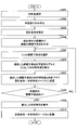
- FIG. 17 is a flowchart of the model learning process executed by the expert terminal 2.
- step S101 the learning condition setting unit 41 reads the data file for model learning. For example, as shown in the input screen 41A of FIG. 4, the data file is selected and read according to the operator's selection operation using the file selection box 40A of the model learning interface I1.
- step S102 the learning condition setting unit 41 visualizes the read data. For example, as shown in the input screen 41A of FIG. 4, the data set included in the read data file is displayed in a table, and the numerical values included in the data set are shown in a histogram, a scatter diagram, or the like.
- step S103 the learning condition setting unit 41 divides the data set included in the read data file into training data and test data. For example, as shown in the input screen 41B of FIG. 5, the data is divided based on various conditions set by the operator.
- step S104 the model learning unit 42 preprocesses the data set for model learning. For example, as shown in the input screen 41C of FIG. 6, preprocessing such as variable transformation and normalization is performed based on various conditions related to preprocessing set by the operator.
- step S105 the model learning unit 42 executes machine learning of the model. For example, as shown in the input screen 41D of FIG. 7, machine learning of the model is performed based on various conditions related to machine learning set by the operator.
- step S106 the model learning unit 42 verifies the prediction accuracy. For example, as shown in the input screen 41E of FIG. 8, the verification process is performed based on various conditions of accuracy verification set by the operator.
- step S107 the model learning unit 42 determines whether or not the prediction accuracy is sufficient. For example, as shown in the input screen 41E of FIG. 8, it can be determined that the prediction accuracy is sufficient when the condition of the verification result set by the operator is satisfied. When the prediction accuracy is insufficient (No in step S107), the process returns to step S104 and machine learning of the model is repeated. When the prediction accuracy is sufficient (Yes in step S107), the process proceeds to step S108.
- step S108 the trained model is output as a file by the model transmission unit 43. Further, the model transmission unit 43 outputs the trained model and a name file including various names (material name, material property name, design condition item name) set in FIG. When the process of step S108 is completed, this control flow ends.
- a series of processes by the expert terminal 2 of the flowchart shown in FIG. 17 performs machine learning of a model in which the correspondence between the design condition of the material to be designed and the material property value is input / output in the material design method according to the present embodiment. Corresponds to "learning steps to be performed”.
- FIG. 18 is a flowchart of the forward problem analysis process executed by the forward problem analysis unit 10 of the general-purpose terminal 3.
- the general-purpose terminal 3 uses the trained model 13 in which the correspondence between the input information including the design conditions of the material to be designed and the output information including the material characteristic values is acquired by machine learning.
- Material design interface I2 is available.
- step S201 the design condition setting unit 11 selects the material name of the material to be designed. For example, as shown in the input screen 11A of FIG. 11, the material name is selected according to the operator's selection operation via the pull-down list 10A of the material design interface I2.
- step S202 the design condition setting unit 11 calls and reads the learned model associated with the material name selected in step S201.
- step S203 the design condition setting unit 11 sets a designated range of design conditions for the material to be designed (design condition setting step). For example, the design condition setting unit 11 displays the input screen 11A shown in FIG. 11 on the material design interface I2, and causes the material designer to input a designated range.
- step S204 the coverage prediction point generation unit 12 generates a plurality of coverage prediction points within the specified range of the design conditions set in step S203 (coverage prediction point generation step).
- the forward problem analysis unit 10 inputs the coverage prediction points generated in step S204 into the trained model 13, and the data characteristic values calculated are associated with each point of the coverage prediction points.
- the set is stored in the design condition-material property table 14 (data set creation step).
- step S205 one comprehensive prediction point is selected, and in step S206, the comprehensive prediction point selected in step S205 is input to the trained model 13 to calculate the material property value.
- step S207 the input coverage prediction point of the trained model 13 selected in step S205 and the material characteristic value of the output are associated and stored in the design condition-material characteristic table 14.
- One data set is generated by the processing of steps S205 to S207.
- step S208 it is determined whether or not there is an unselected comprehensive prediction point. If there is an unselected comprehensive prediction point (YES in step S208), the process returns to step S205 and the data set generation is repeated. If all the coverage prediction points have been selected (NO in step S208), the data set generation is completed and the process proceeds to step S209.
- step S209 the information display unit 31 displays the material properties of each coverage prediction point calculated in step S206 on the material design interface I2.
- the information display unit 31 displays, for example, the output screen 31A illustrated in FIG. 12 on the material design interface I2.
- step S210 the forward problem analysis unit 10 inputs the coverage prediction points generated by the coverage prediction point generation unit 12 into the trained model 13, and the material property values calculated are associated with each point of the coverage prediction points. Data sets are created and these data sets are stored in the design condition-material property table 14. The design condition-material property table 14 is stored in association with the material name selected on the input screen 11A of FIG. When the process of step S210 is completed, the forward problem analysis process of this control flow is completed.
- FIG. 19 is a flowchart of the inverse problem analysis process executed by the inverse problem analysis unit 20 and the design condition adjustment unit 32 of the general-purpose terminal 3.
- step S301 the material name of the material to be designed is selected by the required characteristic setting unit 21.
- the material name is selected according to the operator's selection operation via the pull-down list 10A of the material design interface I2.
- step S302 the required characteristic setting unit 21 calls and reads the design condition-material characteristic table 14 associated with the material name selected in step S301.
- step S303 the required characteristic setting unit 21 sets the specified range of the required characteristics of the material to be designed (required characteristic setting step).
- the required characteristic setting unit 21 displays, for example, the input screen 21A shown in FIG. 13 on the material design interface I2, and causes the material designer to input a designated range.
- step S304 the design condition extraction unit 22 extracts a data set satisfying the required characteristics set in step S303 from the design condition-material characteristic table 14 (design condition extraction step).
- step S305 the range of the material composition and the required characteristics that satisfy the required characteristics specified in step S303 are set on the material design interface I2 by using the data set extracted in step 304 by the information display unit 31. Is displayed in.
- the information display unit 31 displays, for example, the output screen 31B illustrated in FIG. 14 on the material design interface I2.
- step S306 the design condition adjusting unit 32 determines whether or not the material designer has operated the composition adjustment on the output screen 31B showing the range of the material composition satisfying the required characteristics.
- the material designer can perform an operation of changing the positions of the maximum value and the minimum value of the box plot of the material composition of the output screen 31B (design condition adjustment step).
- the design condition adjusting unit 32 outputs the information of the adjusted composition range to the design condition extraction unit 22, and proceeds to step S307. If there is no operation (No in step S306), the inverse problem analysis process of this control flow is terminated.
- step S307 since the composition adjustment operation was detected in step S306, the design condition extraction unit 22 narrows down the data satisfying the material composition after adjusting the composition range from the data set group extracted in step S304. (Narrowing down step).
- step S308 the information display unit 31 updates the output screen 31B of the required characteristics displayed in step S305 using the data set narrowed down in step 307.
- the process of step S308 is completed, the inverse problem analysis process ends.
- the series of processes by the general-purpose terminal 3 of the flowcharts shown in FIGS. 18 and 19 is for the specific design target material created in the learning step for the specific design target material in the material design method according to the present embodiment.
- the general-purpose terminal 3 may be configured to analyze only one of the forward problem and the inverse problem.
- the relationship between the model input and the output is replaced with that of the above embodiment, the model input is the material property, and the model output is the design condition.
- the inverse problem is analyzed using this trained model of the input / output relationship.
- the general-purpose terminal 3 may be configured to perform processing using the learned model 13 created by the expert terminal 2.
Landscapes
- Engineering & Computer Science (AREA)
- Physics & Mathematics (AREA)
- Theoretical Computer Science (AREA)
- Evolutionary Computation (AREA)
- Geometry (AREA)
- General Physics & Mathematics (AREA)
- General Engineering & Computer Science (AREA)
- Computer Hardware Design (AREA)
- Software Systems (AREA)
- Medical Informatics (AREA)
- Computer Vision & Pattern Recognition (AREA)
- Artificial Intelligence (AREA)
- Pure & Applied Mathematics (AREA)
- Mathematical Analysis (AREA)
- Mathematical Optimization (AREA)
- Computational Mathematics (AREA)
- Computing Systems (AREA)
- Life Sciences & Earth Sciences (AREA)
- Bioinformatics & Cheminformatics (AREA)
- Bioinformatics & Computational Biology (AREA)
- Management, Administration, Business Operations System, And Electronic Commerce (AREA)
- Feedback Control In General (AREA)
Abstract
材料設計システムは、設計対象材料の設計条件と、材料特性値との対応関係を入出力とするモデルの機械学習を行うためのモデル学習用インタフェイスを利用可能なエキスパート端末と、特定の設計対象材料について、エキスパート端末により作成された特定の設計対象材料のための学習済みモデルを用いて、設計条件から材料特性値を、または、材料特性値から設計条件を推定するための材料設計用インタフェイスを利用可能な複数の汎用端末と、を備える。
Description
本開示は、材料設計システム、材料設計方法、及び材料設計プログラムに関する。
従来、複数の組成からなる材料、または、複数の製造条件の組合せにより製造される材料を設計する際には、材料開発者の経験に基づき材料の組成や製造条件を調整しながら試作を繰り返すことによって、所望の材料特性を実現し得る最適解が求められる。しかし材料開発者の経験に基づいた試作は、多くの場合最適設計を得るまで試作を繰り返す必要があり、時間と手間を要する。また、材料開発者が過去に行った設計条件の近傍で局所的に条件探索が行われることが多く、大域的な最適設計条件の探索には向かない。
また、第一原理計算などのシミュレーション技術を利用した材料の設計が行われることもある。この場合、シミュレーション技術者が設定した条件で材料特性予測を行う順問題解析を実施することになる。しかし、第一原理計算などシミュレーション技術を利用した材料の設計においても、シミュレーション技術者が経験に基づいて設定した条件における結果を出力する。また、通常、シミュレーションは結果取得まで長時間実行する必要があり、短時間での予測や網羅的な材料設計の探索には向かない。
また、過去の実験・評価データベースを使用した材料の設計や、最近ではデータベースに機械学習を適用した材料特性の予測(順問題解析)を行うことがある。機械学習をうまく進めるには、適切な学習手法の選択、目的変数の選択、及び学習用の各種ハイパーパラメータの調整が重要であり、この設定によって学習結果に差異が出る場合がある。近年は、機械学習用のプラットフォームをユーザに提供して、ユーザがプラットフォームを介した操作を行うことによって、ユーザの機械学習に関する熟練度によらずに、より簡易に適切な学習結果を提供する技術が提案されている(例えば特許文献1参照)。
ところで、機械学習のパラメータ設定においては、操作や設定手順が簡略されたとしても、材料設計者などの機械学習に関する非熟練者が行う難易度は依然として高いと考えられる。やはり統計学、機械学習、計算機科学、情報科学などに精通したデータサイエンティストなどの熟練者によって機械学習を行うほうが、より適切な設定が可能であり依然として有利である。しかし、材料設計分野においてはデータサイエンティストのマンパワーが少なく、各材料設計システムの周囲に機械学習の専門家が必ずしもいるとは限らない。
本開示は、少数の機械学習の熟練者のノウハウを活用して、広範囲で高品質な機械学習の学習結果を利用できる材料設計システム、材料設計方法、及び材料設計プログラムを提供することを目的とする。
本開示は、以下に示す構成を備える。
[1] 複数の組成からなる材料、または、複数の製造条件の組合せにより製造される材料を含む設計対象材料を設計するための材料設計システムであって、
前記設計対象材料の設計条件と、材料特性値との対応関係を入出力とするモデルの機械学習を行うためのモデル学習用インタフェイスを利用可能なエキスパート端末と、
特定の前記設計対象材料について、前記エキスパート端末により作成された前記特定の設計対象材料のための学習済みモデルを用いて、前記設計条件から前記材料特性値を、または、前記材料特性値から前記設計条件を推定するための材料設計用インタフェイスを利用可能な複数の汎用端末と、
を備える材料設計システム。
前記設計対象材料の設計条件と、材料特性値との対応関係を入出力とするモデルの機械学習を行うためのモデル学習用インタフェイスを利用可能なエキスパート端末と、
特定の前記設計対象材料について、前記エキスパート端末により作成された前記特定の設計対象材料のための学習済みモデルを用いて、前記設計条件から前記材料特性値を、または、前記材料特性値から前記設計条件を推定するための材料設計用インタフェイスを利用可能な複数の汎用端末と、
を備える材料設計システム。
[2] 前記エキスパート端末により作成された前記学習済みモデルを保存する中間装置を備え、
前記複数の汎用端末は、前記中間装置に保存される前記学習済みモデルを利用して、前記設計条件から前記材料特性値を、または、前記材料特性値から前記設計条件を推定する、
[1]に記載の材料設計システム。
前記複数の汎用端末は、前記中間装置に保存される前記学習済みモデルを利用して、前記設計条件から前記材料特性値を、または、前記材料特性値から前記設計条件を推定する、
[1]に記載の材料設計システム。
[3] 前記モデル学習用インタフェイスと前記材料設計用インタフェイスとの間の通信はネットワーク回線を介して行われる、
[1]または[2]に記載の材料設計システム。
[1]または[2]に記載の材料設計システム。
[4] 前記モデル学習用インタフェイスと、前記材料設計用インタフェイスとは、クラウドサーバに搭載され、前記モデル学習用インタフェイスと前記材料設計用インタフェイスとの間の通信は前記クラウドサーバ内の通信で行われる、
[1]または[2]に記載の材料設計システム。
[1]または[2]に記載の材料設計システム。
[5] 前記モデル学習用インタフェイスと、前記材料設計用インタフェイスとは、互いに互換性のある別個のソフトウェアに搭載される、
[1]または[2]に記載の材料設計システム。
[1]または[2]に記載の材料設計システム。
[6] 前記エキスパート端末は、
前記モデルの機械学習の各種条件を設定する学習条件設定部と、
前記各種条件に基づき前記モデルの機械学習を行うモデル学習部と、
前記学習済みモデルを出力するモデル出力部と、
を備える、
[1]~[5]のいずれか1項に記載の材料設計システム。
前記モデルの機械学習の各種条件を設定する学習条件設定部と、
前記各種条件に基づき前記モデルの機械学習を行うモデル学習部と、
前記学習済みモデルを出力するモデル出力部と、
を備える、
[1]~[5]のいずれか1項に記載の材料設計システム。
[7] 前記汎用端末は、
前記設計対象材料の設計条件の指定範囲を設定する設計条件設定部と、
前記設計条件設定部により設定された指定範囲内で複数の網羅予測点を生成する網羅予測点生成部と、
前記網羅予測点生成部により生成された網羅予測点を前記学習済みモデルに入力して算出した材料特性値を、前記網羅予測点の各点と紐づけたデータセットを記憶する設計条件-材料特性テーブルと、
前記設計対象材料の要求特性の指定範囲を設定する要求特性設定部と、
前記要求特性設定部により設定された要求特性を満たすデータセットを前記設計条件-材料特性テーブルから抽出する設計条件抽出部と、
を備える、
[1]~[6]のいずれか1項に記載の材料設計システム。
[8] 前記汎用端末は、
前記設計条件抽出部により抽出されたデータセットの設計条件の範囲を調整する設計条件調整部を備え、
前記設計条件抽出部は、前記抽出したデータセットから、前記設計条件調整部により調整された設計条件を満たすデータセットをさらに絞り込む、
[7]に記載の材料設計システム。
前記設計条件抽出部により抽出されたデータセットの設計条件の範囲を調整する設計条件調整部を備え、
前記設計条件抽出部は、前記抽出したデータセットから、前記設計条件調整部により調整された設計条件を満たすデータセットをさらに絞り込む、
[7]に記載の材料設計システム。
[9] 複数の組成からなる材料、または、複数の製造条件の組合せにより製造される材料を含む設計対象材料を設計するための材料設計方法であって、
前記設計対象材料の設計条件と、材料特性値との対応関係を入出力とするモデルの機械学習を行う学習ステップと、
特定の前記設計対象材料について、前記学習ステップにて作成された前記特定の設計対象材料のための学習済みモデルを用いて、前記設計条件から前記材料特性値を、または、前記材料特性値から前記設計条件を推定する推定ステップと、
を含む材料設計方法。
前記設計対象材料の設計条件と、材料特性値との対応関係を入出力とするモデルの機械学習を行う学習ステップと、
特定の前記設計対象材料について、前記学習ステップにて作成された前記特定の設計対象材料のための学習済みモデルを用いて、前記設計条件から前記材料特性値を、または、前記材料特性値から前記設計条件を推定する推定ステップと、
を含む材料設計方法。
[10] 複数の組成からなる材料、または、複数の製造条件の組合せにより製造される材料を含む設計対象材料を設計するための材料設計プログラムであって、
前記設計対象材料の設計条件と、材料特性値との対応関係を入出力とするモデルの機械学習を行う学習機能と、
特定の前記設計対象材料について、前記学習機能により作成された前記特定の設計対象材料のための学習済みモデルを用いて、前記設計条件から前記材料特性値を、または、前記材料特性値から前記設計条件を推定する推定機能と、
をコンピュータに実現させるための材料設計プログラム。
前記設計対象材料の設計条件と、材料特性値との対応関係を入出力とするモデルの機械学習を行う学習機能と、
特定の前記設計対象材料について、前記学習機能により作成された前記特定の設計対象材料のための学習済みモデルを用いて、前記設計条件から前記材料特性値を、または、前記材料特性値から前記設計条件を推定する推定機能と、
をコンピュータに実現させるための材料設計プログラム。
本開示によれば、少数の機械学習の熟練者のノウハウを活用して、広範囲で高品質な機械学習の学習結果を利用できる材料設計システム、材料設計方法、及び材料設計プログラムを提供することができる。
以下、添付図面を参照しながら実施形態について説明する。説明の理解を容易にするため、各図面において同一の構成要素に対しては可能な限り同一の符号を付して、重複する説明は省略する。
[材料設計システムの全体構成]
図1、図2を参照して実施形態に係る材料設計システム1の構成を説明する。図1は、実施形態に係る材料設計システム1の概略構成を示すブロック図である。材料設計システム1は、複数の組成からなる材料、または、複数の製造条件の組合せにより製造される材料を含む設計対象材料を設計するための装置である。
図1、図2を参照して実施形態に係る材料設計システム1の構成を説明する。図1は、実施形態に係る材料設計システム1の概略構成を示すブロック図である。材料設計システム1は、複数の組成からなる材料、または、複数の製造条件の組合せにより製造される材料を含む設計対象材料を設計するための装置である。
材料設計システム1は、合成ゴム、合成樹脂、合成エラストマーなどの有機材料、合金、鋼などの金属材料、さらに無機材料や複合材料といった材料全般の設計に適用可能である。要は、材料設計システム1の設計対象材料は、複数の組成からなる材料、または複数の製造条件・処理(温度、圧力、加工、酸化処理、酸処理、配合、混合、撹拌など)の組み合わせにより製造される材料全般を含む。
図1に示すように、材料設計システム1は、単一のエキスパート端末2と、複数(図1では2台)の汎用端末3とを備える。
エキスパート端末2は、モデル学習用インタフェイスI1を利用可能な装置である。モデル学習用インタフェイスI1は、設計対象材料の設計条件と、材料特性値との対応関係を入出力とするモデルの機械学習を行うためのインタフェイスである。モデル学習用インタフェイスI1は、GUI(グラフィカル・ユーザ・インタフェイス)、またはコマンドによるプログラミングを用いるためのAPI(アプリケーション・プログラミング・インタフェイス)である。エキスパート端末2のモデル学習用インタフェイスI1は、データサイエンティストなどの機械学習の熟練者が利用する。
汎用端末3は、特定の前記設計対象材料について、材料設計用インタフェイスI2を利用可能な装置である。材料設計用インタフェイスI2は、エキスパート端末2により作成された特定の設計対象材料のための学習済みモデルを用いて、設計条件から材料特性値を推定する、または、材料特性値から設計条件を推定するためのインタフェイスである。材料設計用インタフェイスI2は、ユーザ操作性の高いGUIである。汎用端末3の材料設計用インタフェイスI2は、材料設計者などの機械学習の非熟練者、すなわち非データサイエンティストが利用する。
汎用端末3は、例えば材料設計システム1が一企業内に設置されている場合、企業内に複数ある設計部門ごとに設置される。このとき、汎用端末3は全ての部門に設置される必要はない。図1の例では、部門Aと部門Bの二つの部門が例示され、部門Aでは設計対象材料として材料A、Bの設計が行われ、部門Bでは設計対象材料として材料B、Cの設計が行われる場合が例示されている。
エキスパート端末2ではモデル学習用インタフェイスI1を利用して学習済みモデルが作成される。エキスパート端末2と汎用端末3とは通信可能に接続されており、エキスパート端末2から学習済みモデルが各汎用端末3に送信される。この例の場合、エキスパート端末2は、設計対象材料の材料A、B、Cにそれぞれ用いる三種類の学習済みモデルを作成し、各部門で扱う材料に応じて学習済みモデルを各部門の汎用端末3に送信する。図1の例では、材料A、Bを扱う部門Aの汎用端末3には、材料A用学習済みモデルと材料B用学習済みモデルが送信され、材料B、Cを扱う部門Bの汎用端末3には、材料B用学習済みモデルと材料C用学習済みモデルが送信されている。
材料設計システム1では、独立して動作可能なモデル学習用インタフェイスI1と材料設計用インタフェイスI2とがネットワーク接続などによって連携することができる。材料設計用インタフェイスI2は、非データサイエンティストである材料開発者が機械学習を実施しなくても材料設計を行うことができるよう構成される。また、材料設計用インタフェイスI2は、材料の種類に依らない汎用性の高いデザインになっており、モデル学習用インタフェイスI1からのファイル転送などによる情報の提供により、あらゆる種類の材料の開発に適用できるよう構成されている。
図1に示すように、材料設計システム1では、モデル学習用インタフェイスI1を利用可能なエキスパート端末2は、材料設計用インタフェイスI2を利用可能な汎用端末3より少数であり、各端末2,3が別装置である。これにより、本実施形態に係る材料設計システム1は、エキスパート端末2で作成された学習済みモデルを多数の汎用端末3で共用することができるので、少数の機械学習の熟練者のノウハウを活用して、高品質な機械学習の学習結果を複数の材料設計部門で利用できる。すなわち広範囲で高品質な機械学習の学習結果を利用できるという効果を奏することができる。
一般に、機械学習と、その基礎となる統計学、計算機科学、情報科学を習得するためには多大な労力、費用、時間を要するため、データ分析の専門家ではない(非データサイエンティストの)材料開発者には高度な機械学習の実施は困難である。また世間でもデータサイエンティストの不足が叫ばれており、材料メーカーの組織内で十分な人員を確保することが困難である。このような問題に対して、本実施形態の材料設計システム1では、上記のとおり、汎用端末3に対して少数のエキスパート端末2を設ける構成とすることによって、少人数のデータサイエンティストを確保するだけで、材料メーカーの組織内、あるいは組織外の多数の材料開発部門に効率的に材料設計を支援するシステムを展開することができる。
なお、本実施形態では、材料設計システム1が一企業内に設置され、汎用端末3が企業内に複数ある設計部門ごとに設置される構成を例示したが、材料設計システム1の設置態様はこれに限られない。例えば複数の企業や組織に横断的に一つの材料設計システム1が設置され、各企業または組織ごとに汎用端末3が設置される構成でもよい。または、材料設計システム1がある一つのグループ内に設置され、汎用端末3がこのグループ内に用途に応じて複数台設置される構成でもよい。
図2は、実施形態に係る材料設計システム1の概略構成の変形例を示すブロック図である。図2に示すように、材料設計システム1は、エキスパート端末2により作成された学習済みモデルを保存する中間装置4を備える構成でもよい。図2の構成では、複数の汎用端末3は、中間装置4に保存される学習済みモデルを利用して、設計条件から材料特性値を、または、材料特性値から設計条件を推定する。
このように中間装置4を備える構成とすることで、各汎用端末3は中間装置4に記憶された学習済みモデルにアクセスして利用することができるので、各汎用端末3が学習済みモデルを利用するために各端末へ学習済みモデルのデータを個別に配布するなどの作業が不要となり、より簡易に学習済みモデルを利用して機械学習を行うことができる。また、各汎用端末3の利用可否の設定を、中間装置4の各学習済みモデルへのアクセス権で行うことができるので、各汎用端末3が利用可能な学習済みモデルの割り当ての管理を容易にできる。
ここで、エキスパート端末2と汎用端末3との間の通信、すなわちモデル学習用インタフェイスI1と材料設計用インタフェイスI2との間の通信は、例えば以下の3つ形態で実現できる。このように様々な通信形態に対応可能とすることで、材料設計システム1の実装のバリエーションを増やすことができ、汎用性を高めることができる。
(形態1:ネットワークシステム)
モデル学習用インタフェイスI1と材料設計用インタフェイスI2との間の通信はネットワーク回線を介して行われる。
モデル学習用インタフェイスI1と材料設計用インタフェイスI2との間の通信はネットワーク回線を介して行われる。
モデル学習用インタフェイスI1が搭載されているサーバ(エキスパート端末2)と、材料設計用インタフェイスI2が搭載されているサーバ(汎用端末3)はネットワークによって接続されており、モデル学習用インタフェイスI1のサーバから材料設計用インタフェイスI2のサーバに学習済みモデルや名称ファイル(材料名、材料特性名、設計条件項目名)といった情報を転送することができる。学習済みモデルはpickleファイル、joblibファイル等の形式を取り、名称ファイルはテキストファイル、CSVファイル、JSONファイル、XMLファイル等の形式を取る。
前述した情報の提供の方法はファイル転送に限らず、フラッシュメモリ等の半導体メモリやDVD-ROM等のディスクメディアといった記録媒体に保持された情報を転送する形式でも良い。
モデル学習用インタフェイスI1から材料設計用インタフェイスI2への情報の転送は、図1に示すように、モデル学習用インタフェイスI1のサーバから材料設計用インタフェイスI2のサーバに直接行っても良いし、図2に示すように、モデル学習用インタフェイスI1から中間サーバやディレクトリ(中間装置4)に転送した上で、材料設計用インタフェイスI2から中間装置4へのアクセスを許可する形式で行っても良い。
(形態2:ウェブサービス)
モデル学習用インタフェイスI1と、材料設計用インタフェイスI2とは、クラウドサーバに搭載され、モデル学習用インタフェイスI1と材料設計用インタフェイスI2との間の通信はクラウドサーバ内の通信で行われる。
モデル学習用インタフェイスI1と、材料設計用インタフェイスI2とは、クラウドサーバに搭載され、モデル学習用インタフェイスI1と材料設計用インタフェイスI2との間の通信はクラウドサーバ内の通信で行われる。
モデル学習用インタフェイスI1と材料設計用インタフェイスI2は、AWS(登録商標;アマゾン・ウェブ・サービス)やGCP(登録商標;グーグル・クラウド・プラットフォーム)といったクラウドサーバに搭載されている別個のインタフェイスであり、クラウドサーバ内での通信が確保されている。クラウドサーバ内のモデル学習用インタフェイスI1のインスタンスから、材料設計用インタフェイスI2のインスタンスへは、学習済みモデルや名称に関する情報が、ファイル転送、あるいはフラッシュメモリ等の半導体メモリやDVD-ROM等のディスクメディアといった記録媒体に保持された情報の転送といった形式で伝達される。
モデル学習用インタフェイスI1から材料設計用インタフェイスI2への情報の転送は、図1に示すように、モデル学習用インタフェイスI1のインスタンスから材料設計用インタフェイスI2のインスタンスに直接行っても良いし、図2に示すように、モデル学習用インタフェイスI1から中間インスタンスやディレクトリ(中間装置4)に転送した上で、材料設計用インタフェイスI2から中間装置4へのアクセスを許可する形式で行っても良い。
(形態3:ソフトウェア)
モデル学習用インタフェイスI1と、材料設計用インタフェイスI2とは、互いに互換性のある別個のソフトウェアに搭載される。
モデル学習用インタフェイスI1と、材料設計用インタフェイスI2とは、互いに互換性のある別個のソフトウェアに搭載される。
モデル学習用インタフェイスI1のソフトウェアは学習済みモデルや名称ファイルを外部に出力することができ、材料設計用インタフェイスI2のソフトウェアはその学習済みモデルや名称ファイルを読み込むことができる。
なお、図1、図2の例では、モデル学習用インタフェイスI1を利用可能なエキスパート端末2と、材料設計用インタフェイスI2を利用可能な汎用端末3とが別装置である構成を例示したが、エキスパート端末2と汎用端末3の少なくとも1つとが同一の装置でもよい。単一装置内でもモデル学習用インタフェイスI1に対して、多数の材料設計用インタフェイスI2を利用可能であれば、少数の機械学習の熟練者のノウハウを活用して、高品質な機械学習の学習結果を複数の材料設計部門で利用できる。すなわち広範囲で高品質な機械学習の学習結果を利用できるという効果を得られる。
[エキスパート端末の機能説明]
図3~図9を参照して、エキスパート端末2の機能構成を説明する。図3は、エキスパート端末2の機能ブロック図である。
図3~図9を参照して、エキスパート端末2の機能構成を説明する。図3は、エキスパート端末2の機能ブロック図である。
図3に示すように、エキスパート端末2は、学習条件設定部41と、モデル学習部42と、モデル送信部(モデル出力部)43とを備える。
学習条件設定部41は、モデルの機械学習の各種条件を設定する。
図4~図9は、モデル学習用インタフェイスI1における学習条件設定部41の入力画面41A~41Fの一例を示す図である。
図4に示すように入力画面41Aは、「データ可視化」のタブ付きウィンドウとして表示されている。入力画面41Aには、モデル学習用のデータファイルの内容が様々な態様で表示されている。モデル学習用インタフェイスI1では、CSV形式などのデータファイルの読み込みを行う機能を備え、図4ではファイル選択ボックス40Aにて「Y合金データ.csv」というデータファイルが選択されて読み込まれている。このデータファイルには、Y合金に関するモデル入力(設計条件)とモデル出力(材料特性値)のデータセットの組が大量に記録されている。図4の入力画面41Aでは、読み込んだデータファイルに含まれるデータセットがテーブル表示され、また、データセットに含まれる数値をヒストグラムや散布図などで図示されている。
図5に示すように、入力画面41Bは、「データ分割」のタブ付きウィンドウとして表示されている。入力画面41Bでは、読み込んだデータファイルに含まれるデータセットを、訓練データと試験データにどのように分割するかの各種条件(試験データの割合、乱数シードなど)の数値を入力可能となっている。
図6に示すように、入力画面41Cは、「前処理」のタブ付きウィンドウとして表示されている。入力画面41Cでは、データセットに含まれる変数を、関数などを用いて変換したり正規化したりする設定や、データセットに含まれる変数の次元を、例えば主成分分析(PCA(principal component analysis))を用いて圧縮するための設定、データセットに含まれる変数をモデルの目的変数、説明変数に割り当てる設定などを入力可能となっている。
なお図6の画面例では、変数変換の項目欄に「+」ボタン41C1が表示されているが、例えばこの「+」ボタン41C1を押下することで、手法などの記入欄を追加することができる。
図7に示すように、入力画面41Dは、「機械学習」のタブ付きウィンドウとして表示されている。入力画面41Dでは、機械学習手法の選択や、ハイパーパラメータチューニングの設定などを入力可能となっている。なお、図7の画面例では、ハイパーチューニングパラメータの範囲として「(100、1000、100)」が記入されているが、これらの数値は、ハイパーチューニングパラメータの範囲の(最小、最大、刻み幅)を示す。
図8に示すように、入力画面41Eは、「精度検証」のタブ付きウィンドウとして表示されている。入力画面41Eでは、学習済みモデルの予測精度を交差検証により評価する機能の設定や、学習済みモデルの予測精度を、試験データを用いて評価する機能の設定や、学習済みモデルによる予測結果を図示する機能の設定を入力可能となっている。
図9に示すように、入力画面41Fは、「名称作成」のタブ付きウィンドウとして表示されている。入力画面41Fでは、モデルの名称及び材料名を指定した上で、学習済みモデルを外部に出力する。また、入力画面41Fでは、材料名、材料特性名、設計条件項目名を入力することができ、それらをテキストファイル、CSVファイル、JSONファイル、XMLファイル等の形式で外部に出力する設定を入力可能となっている。材料特性名、設計条件項目名の各名称は手動で入力することもできるし、読み込んだデータファイルに記載された名称を機械的に反映させても良い。材料特性名ファイル、設計条件項目名ファイルは材料名に紐づいている。材料特性名ファイルと設計条件項目名ファイルは材料特性名と設計条件項目名の各名称のみ入力されていても良いし、それぞれの取り得る値の範囲の既定値が入力されていても良い。
なお、入力画面41A~41Fは、図4~図9に示すようにタブによって切り替えても良いし、入力画面41A~41Fに備わる機能にそれぞれ対応するアイコンと、アイコン間をつなげる矢印を用いて解析フローが構成され、解析フローに沿って学習条件の設定がされても良い。
図3に戻り、モデル学習部42は、学習条件設定部41により設定された各種条件に基づきモデルの機械学習を行う。モデル学習用インタフェイスI1の「解析実行」ボタン40Bを押下することで、図4~図8で設定された学習条件下でモデルの機械学習が実施される。図1~図3の例では、設計対象材料の材料A、B、Cにそれぞれ割り当てられる「材料A用モデル」、「材料B用モデル」、「材料C用モデル」について機械学習を行って、材料A、B、Cの設計に用いる学習済みモデルを個別に作成する。
なお、モデル学習部42では、回帰、およびクラス分類といった機械学習を行うことができ、手法としては線形、一般化線形(ラッソ、リッジ、エラスティックネット、ロジスティック)、カーネルリッジ、ベイズリッジ、ガウス過程、k近傍法、決定木、ランダムフォレスト、アダブースト、バギング、勾配ブースティング、サポートベクターマシン、ニューラルネットワーク、ディープラーニングなどを用いることができる。
モデル送信部43は、学習済みモデルを出力する。モデルの名称及び材料名を指定した上で、モデル学習用インタフェイスI1の「モデル出力」ボタン40Cを押下することで、学習済みモデルが外部に出力される。また、「名称出力」ボタン40Dを押下することで、図9で設定された各種名称(材料名、材料特性名、設計条件項目名)を含む名称ファイルが外部に出力される。
このように、エキスパート端末2は、モデルの機械学習の各種条件を設定する学習条件設定部41と、各種条件に基づきモデルの機械学習を行うモデル学習部42と、学習済みモデル13を出力するモデル送信部43と、を備える。これにより、モデルの機械学習の各種条件を詳細に調整することが可能となるので、様々な用途に適した機械学習を行うことができる。また、エキスパート端末2は、データサイエンティストなどの機械学習の熟練者が利用すれば、熟練者の知見に基づきより適切な条件設定が期待できるので特に有効である。
[汎用端末の機能説明]
図10~図15を参照して、汎用端末3の機能構成を説明する。図10は、汎用端末3の機能ブロック図である。
図10~図15を参照して、汎用端末3の機能構成を説明する。図10は、汎用端末3の機能ブロック図である。
図4に示すように、汎用端末3は、順問題解析部10と、逆問題解析部20と、入出力部30と、を備える。順問題解析部10は、学習済みモデル13を用いて、材料設計者の所望の設計条件を満たす材料特性を出力する。逆問題解析部20は、順問題解析部10の出力結果に基づき作成される設計条件-材料特性テーブル14を用いて、材料設計者の所望の要求特性を満たす設計条件を出力する。入出力部30は、順問題解析部10及び逆問題解析部20の出力結果を表示して材料設計者に提示したり、材料設計者による出力結果の調整操作を受け付ける。
順問題解析部10は、設計条件設定部11と、網羅予測点生成部12と、学習済みモデル13と、設計条件-材料特性テーブル14と、を有する。
設計条件設定部11は、設計対象材料の設計条件の指定範囲を設定する。設計条件設定部11は、例えば材料設計用インタフェイスI2上に設計条件の入力画面を表示して材料設計者に設計対象材料の種類と設計条件の指定範囲の入力を促すことによって、設計対象材料の設計条件の指定範囲を設定できる。
図11は、材料設計用インタフェイスI2における設計条件設定部11の入力画面11Aの一例を示す図である。材料設計用インタフェイスI2では、この入力画面11Aは、「設計条件」のタブ付きウィンドウとして表示されている。材料設計用インタフェイスI2では、設計対象の材料名を選択するためのプルダウンリスト10Aが表示され、図11では設計対象材料として「Y合金」が選択されている。この場合、例えば設計条件設定部11は、図9を参照して説明した名称ファイルを読み込んで、選択可能な材料名のプルダウンリスト10Aを作成することができる。また、設計条件設定部11は、選択された材料名に紐づけられた学習済みモデルを読み込む。
設計条件は、原料の組成に関する項目(図11では「原料A」、「原料B」)や、製造条件に関する項目(図11では「処理温度」)を含む。入力画面11Aでは、プルダウンメニューで条件パターンを選択可能となっている。この場合、例えば、設計条件設定部11は、図9を参照して説明した名称ファイルを読み込んで、選択可能な条件パターンのプルダウンメニューを作成する。条件パターンとして選択可能な項目は、材料名に紐づけられて決まっている。
原料の組成の項目としては、例えば設計対象材料がアルミニウム(Al)合金の場合、Si、Fe、Cu、Mn、Mg、Cr、Ni、Zn、Ti、Na、V、Pb、Sn、B、Bi、Zr、Oなどの元素種を添加物として質量百分率(質量%)で含む。なお、Alの質量百分率は、100%-(上記元素の質量百分率の和)によって表される。
製造条件の項目としては、例えば設計対象材料がアルミニウム合金の場合、熱処理に関する項目は、焼きなまし、溶体化処理、人工時効硬化処理、自然時効処理、熱間加工処理、冷間加工処理、安定化処理などの各処理の温度(℃)及び実施時間(h)を含み、加工条件に関する項目は、加工率、押比、減面率、製品形状などを含む。
入力画面11Aにおいて条件パターンを選択して、設計条件を設定後、材料設計用インタフェイスI2の「解析実行」ボタン10Bを押下することで、順問題解析部10の処理が開始される。
網羅予測点生成部12は、設計条件設定部11により設定された設計条件の指定範囲内で複数の網羅予測点を生成する。例えば、組成項目のSiの質量百分率と、製造条件項目の焼きなましの実施時間の範囲が指定された場合には、まずSi質量百分率の指定範囲、及び、焼きなまし実施時間の指定範囲内でそれぞれランダムまたは所定の刻み幅で複数の数値が算出され、各項目の複数の数値同士の全ての組合せが作成される。これらの組合せが網羅予測点として出力される。
学習済みモデル13は、設計対象材料の設計条件を含む入力情報と、材料特性値を含む出力情報との対応関係を、機械学習により既に取得して定式化したものである。学習済みモデル13は、図11の例では、設計対象材料が「Y合金」の場合に用いる学習済みモデルがエキスパート端末2によって作成され、汎用端末3が利用可能となっている。
材料特性の項目としては、引張強度、0.2%耐力、伸び、線膨張係数、ヤング率、ポワソン比、疲労特性、硬さ、クリープ強度やクリープ歪みを含むクリープ特性、せん断強度、比熱、熱伝導率、電気抵抗率、密度、固相線、液相線などを含む。
図12は、材料設計用インタフェイスI2における順問題解析部10の出力画面31Aの一例を示す図である。材料設計用インタフェイスI2では、この出力画面31Aは、「結果(材料特性)」のタブ付きウィンドウとして表示されている。出力画面31Aは、例えば情報表示部31を介して材料設計用インタフェイスI2上に表示される。図12では、学習済みモデル13の出力(材料特性)は、説明の簡略化のため「引張強度」、「線膨張係数」及び「ヤング率」の3つのみに限定されているがこの限りではない。図12の例では、各材料特性の値の範囲が箱ひげ図によって表示されている。
設計条件-材料特性テーブル14は、網羅予測点生成部12により生成された網羅予測点を学習済みモデル13に入力して算出した材料特性値を、網羅予測点の各点と紐づけたデータセットを記憶する。順問題解析部10は、学習済みモデル13により網羅予測点の演算を行うと、出力を網羅予測点(入力)と紐づけて設計条件-材料特性テーブル14に記憶させる。設計条件-材料特性テーブル14では、学習済みモデルの入力(製造条件、材料組成)と出力(材料特性)とが1つのデータセットとして纏められて、設計条件-材料特性テーブル14の同一行に記録される。設計条件-材料特性テーブル14の各行は個々のデータセットであり、各列は学習済みモデル13の入力及び出力の各項目の数値が記録される。設計条件-材料特性テーブル14は、図11の入力画面11Aで選択された材料名と紐づけられて記憶される。
このように、順問題解析部10は、材料設計者が多次元の設計条件の範囲を指定する操作を行うだけで、多次元の設計条件の範囲内をすべて網羅する設計条件と材料特性とのデータセット群を自動生成できるよう構成される。
逆問題解析部20は、要求特性設定部21と、設計条件抽出部22と、を有する。また、上述の設計条件-材料特性テーブル14も逆問題解析部20に含まれる。
要求特性設定部21は、設計対象材料の要求特性の指定範囲を設定する。要求特性設定部21は、例えば材料設計用インタフェイスI2上に要求特性の入力画面を表示して材料設計者に指定範囲の入力を促すことによって、要求特性の指定範囲を設定できる。
図13は、要求特性設定部21の入力画面21Aの一例を示す図である。材料設計用インタフェイスI2では、この入力画面21Aは、「要求特性」のタブ付きウィンドウとして表示されている。材料設計用インタフェイスI2では、設計対象の材料名を選択するためのプルダウンリスト10Aが表示され、図13では設計対象材料として「Y合金」が選択されている。この場合、例えば要求特性設定部21は、図9を参照して説明した名称ファイルを読み込んで、選択可能な材料名のプルダウンリスト10Aを作成することができる。また、要求特性設定部21は、選択された材料名に紐づけられた設計条件-材料特性テーブル14を読み込む。
要求特性の項目は、上述した材料特性の項目と同一である。入力画面21Aでは、プルダウンメニューで特性名を選択可能となっている。この場合、例えば、設計条件設定部11は、図9を参照して説明した名称ファイルを読み込んで、選択可能な特性名のプルダウンメニューを作成する。特性名として選択可能な項目は、材料名に紐づけられて決まっている。図13の例では、要求特性として「引張強度」、「線膨張係数」及び「ヤング率」が選択されている。また、入力画面21Aでは、各特性の最大値と最小値とを入力可能となっている。
入力画面21Aにおいて特性名を選択して要求特性を設定後、材料設計用インタフェイスI2の「解析実行」ボタン10Bを押下することで、逆問題解析部20の処理が開始される。
設計条件抽出部22は、要求特性設定部21により設定された要求特性を満たすデータセットを設計条件-材料特性テーブル14から抽出する。
図14は、逆問題解析部20の出力画面31Bの一例を示す図である。材料設計用インタフェイスI2では、この出力画面31Bは、「結果(設計条件)」のタブ付きウィンドウとして表示されている。出力画面31Bは、例えば情報表示部31を介して材料設計用インタフェイスI2上に表示される。図14に示す出力画面31Bでは、図13で設定された要求特性をすべて満たす組成(原料A、原料B)及び製造条件(処理温度)の値の範囲が箱ひげ図によって表示されている。このとき、前述した「結果(材料特性)」のタブ付きウィンドウに切り替えると、各材料特性の値の範囲が、図14で示す設計条件に対応する各材料特性の値の範囲に更新して表示される。
図15は、逆問題解析部20の出力画面の他の例である出力画面31Cを示す図である。材料設計用インタフェイスI2では、この出力画面31Cは、「結果(テーブル)」のタブ付きウィンドウとして表示されている。出力画面31Cは、例えば情報表示部31を介して材料設計用インタフェイスI2上に表示される。図15に示す出力画面31Cでは、図13で設定された要求特性(引張強度、線膨張係数、ヤング率)と、図14に示すこの要求特性をすべて満たす設計条件(原料A、原料B、処理温度)の各値が纏められたテーブルが表示されている。また、このテーブルは、スクロールバーにより表の表示部分の移動が可能な態様としてもよい。
また、出力画面31Cにおいて、材料設計用インタフェイスI2の「結果出力」ボタン10Cを押下することで、図15に示すテーブルをCSVファイルなどの形式で外部に出力することができる。
このように、逆問題解析部20は、材料設計者が多次元の要求特性の範囲を指定する操作を行うだけで、多次元の要求特性を同時に満たす設計条件(材料組成または製造条件)を抽出できるよう構成される。また、逆問題解析にシミュレーションや学習モデルを用いず、順問題解析部10が作成した設計条件-材料特性テーブル14を流用するので、計算コストも格段に低減できる。
入出力部30は、情報表示部31を有する。
情報表示部31は、順問題解析部10や逆問題解析部20の出力を表示する。例えば図14、図15に示すように、設計条件抽出部22により抽出されたデータセットに関する要求特性及び設計条件の範囲を表示する。
入出力部30は、さらに、設計条件調整部32を有してもよい。
設計条件調整部32は、設計条件抽出部22により抽出されたデータセットの設計条件の範囲を調整する。設計条件調整部32は、例えば材料設計用インタフェイスI2上に表示される出力画面31Bの組成範囲を変更する材料設計者の操作入力によって、設計条件の範囲を調整できる。
また、設計条件抽出部22は、要求特性に応じて抽出したデータセット群から、上記の設計条件調整部32により調整された設計条件を満たすデータセット群にさらに絞り込むこともできる。
逆問題解析部20は要求特性を満たす設計条件を出力するが、これらの設計条件はあくまで設計条件-材料特性テーブル14の網羅予測点の中から自動的に抽出したもので、実際の製造の難易度などの製造上の制約は考慮されていない。例えば、ハンドリングが難しくて実際に作るのが難しい、作るのに長時間がかかる、処理に手間がかかる、鋳造するときに巣が入る組成、成形できない、コスト度外視なら製造可能だが通常の工場設備では作れない、など様々な製造上の制約が考えられる。入出力部30が設計条件調整部32を有する場合、逆問題解析部20の出力結果を、設計条件調整部32を用いて材料設計者により調整可能とすることによって、要求特性を満たす製造条件を、材料設計者の経験則に基づき製造上の制約を考慮して絞り込むことができる。つまり、機械学習による予測と材料設計者の経験が協働した材料設計が可能になる。
このように汎用端末3では、順問題解析の実施中に、逆問題解析で利用するデータセット群を作成して設計条件-材料特性テーブル14に記憶する。そして、逆問題解析の実施時には、設計条件-材料特性テーブル14を参照して、要求特性を満たすデータセットを抽出する。つまり逆問題解析では、何らシミュレーションやモデル演算などの数値計算を行わずに、設計条件-材料特性テーブル14を検索する作業のみを行うので、計算コストを大幅に低減でき、所望の材料特性を満たす設計条件の最適解を短時間で導出できる。
また、従来のシミュレーションによる逆問題解析や、逆問題解析に機械学習系を適用したものは、要求特性が複数ある場合には、各特性ごとに順番に調整を行いながら徐々に最適解に到達するよう演算が行われるのであって、複数種の特性を同時に満たすように候補材料の探索を纏めて実施するものではない。複数の材料特性は互いにトレードオフの関係となる場合が多く、最適解の到達まで試行錯誤が繰り返されるので、所望の材料特性を満たす設計条件の最適解を求めるまでの時間が長い。これに対して本実施形態では、学習済みモデル13の出力(材料特性)を複数個に設定して、設計条件-材料特性テーブル14に複数の材料特性の項目を作成しておけば、逆問題解析において、複数種の材料特性を同時に満たすように候補材料の探索を纏めて実施することができる。これにより、要求特性を複数種設定する場合でも、最適解の導出までの所要時間を従来手法より大幅に低減できる。
また、設計条件-材料特性テーブル14に記憶されているデータセット群は、順問題解析において自動生成される大量の網羅予測点から導出された情報なので、設計条件や材料特性の各項目の刻み幅が充分に小さく、分解能が高い。このため、逆問題解析においても要求特性を満たす設計条件の予測を高精度に行うことができる。
また、汎用端末3は、設計条件抽出部22により抽出されたデータセットの設計条件の範囲を調整する設計条件調整部32を備えることが好ましい。汎用端末3が設計条件調整部32を有する場合、設計条件抽出部22は、抽出したデータセットから、設計条件調整部32により調整された設計条件を満たすデータセットをさらに絞り込む。
この場合、要求特性に応じて設計条件抽出部22が設計条件-材料特性テーブル14が機械的に抽出した設計条件に、材料設計者の経験に基づく製造上の制約等を加味して絞り込みを行うことができる。これにより、機械学習による予測と材料設計者の経験が協働した材料設計が可能となり、より製造しやすい設計条件の抽出が可能となる。
また汎用端末3は、設計条件抽出部22により抽出されたデータセットに関する要求特性及び設計条件の範囲を表示する情報表示部31を備える。さらに、汎用端末3が設計条件調整部32を有する場合、設計条件調整部32は、情報表示部31に表示されている設計条件の範囲を変更するユーザ操作に応じて設計条件の範囲を調整する。
汎用端末3が設計条件調整部32を有する場合、材料設計者による設計条件の範囲の調整操作を入出力部30上でより直観的に行うことができ、調整操作の負荷を減らして簡易にできる。また、調整操作による結果を即座に反映できるので、材料設計者によるインタラクティブな調整操作が可能となり、設計条件の範囲の調整をより効率良く行うことができる。
また、汎用端末3で利用可能な材料設計用インタフェイスI2は、図11~図15を参照して説明したように、設計対象の材料名を選択するためのプルダウンリスト10Aで設計対象材料を選択することによって、選択した材料の設計が可能となるので、材料ごとに個別のインタフェイスを用意する必要がなく、複数の材料の設計作業においてインタフェイスを共通化でき、汎用性を向上できる。一般に、材料メーカーにおいては多数の部署で多品種の材料を開発しているため、組織全体に展開可能な汎用性の高いインタフェイスを用意することは非常に有用である。
[各端末のハードウェア構成]
図16は、エキスパート端末2、汎用端末3のハードウェア構成を示すブロック図である。図16に示すように、エキスパート端末2、汎用端末3は、物理的には、CPU(Central Processing Unit)101、主記憶装置であるRAM(Random Access Memory)102およびROM(Read Only Memory)103、入力デバイスであるキーボード及びマウス等の入力装置104、ディスプレイ等の出力装置105、ネットワークカード等のデータ送受信デバイスである通信モジュール106、ハードディスク等の補助記憶装置107、などを含むコンピュータシステムとして構成することができる。
図16は、エキスパート端末2、汎用端末3のハードウェア構成を示すブロック図である。図16に示すように、エキスパート端末2、汎用端末3は、物理的には、CPU(Central Processing Unit)101、主記憶装置であるRAM(Random Access Memory)102およびROM(Read Only Memory)103、入力デバイスであるキーボード及びマウス等の入力装置104、ディスプレイ等の出力装置105、ネットワークカード等のデータ送受信デバイスである通信モジュール106、ハードディスク等の補助記憶装置107、などを含むコンピュータシステムとして構成することができる。
図3に示すエキスパート端末2の各機能、及び図10に示す汎用端末3の各機能は、CPU101、RAM102等のハードウェア上に所定のコンピュータソフトウェア(材料設計プログラム)を読み込ませることにより、CPU101の制御のもとで通信モジュール106、入力装置104、出力装置105を動作させるとともに、RAM102や補助記憶装置107におけるデータの読み出し及び書き込みを行うことで実現される。すなわち、本実施形態の材料設計プログラムをコンピュータ上で実行させることで、材料設計システム1は、図3の学習条件設定部41と、モデル学習部42と、モデル送信部43、図10の設計条件設定部11と、網羅予測点生成部12と、学習済みモデル13と、要求特性設定部21と、設計条件抽出部22と、情報表示部31と、設計条件調整部32として、それぞれ機能する。また、設計対象材料の設計条件と、材料特性値との対応関係を入出力とするモデルの機械学習を行う学習機能と、特定の設計対象材料について、学習機能により作成された特定の設計対象材料のための学習済みモデル13を用いて、設計条件から材料特性値を推定する、または、材料特性値から設計条件を推定する推定機能も実現できる。また、網羅予測点生成機能により生成された網羅予測点を学習済みモデル13に入力して算出した材料特性値を、網羅予測点の各点と紐づけたデータセットを設計条件-材料特性テーブル14に記憶するデータセット作成機能も実現できる。なお、図10に示す設計条件-材料特性テーブル14は、コンピュータが備える記憶装置(RAM102、ROM103、補助記憶装置107など)の一部により実現できる。また、図1、図2などに示すモデル学習用インタフェイスI1、材料設計用インタフェイスI2や、図10に示す入出力部30は、コンピュータが備える出力装置105や入力装置104で実現できる。
本実施形態の材料設計プログラムは、例えばコンピュータが備える記憶装置内に格納される。なお、材料設計プログラムは、その一部又は全部が、通信回線等の伝送媒体を介して伝送され、コンピュータが備える通信モジュール等により受信されて記録(インストールを含む)される構成としてもよい。また、材料設計プログラムは、その一部又は全部が、CD-ROM、DVD-ROM、フラッシュメモリなどの持ち運び可能な記憶媒体に格納された状態から、コンピュータ内に記録(インストールを含む)される構成としてもよい。
[材料設計方法]
図17~図19を参照して、本実施形態に係る材料設計システム1による材料設計方法を説明する。
図17~図19を参照して、本実施形態に係る材料設計システム1による材料設計方法を説明する。
まず図17を参照してエキスパート端末2により実施されるモデル学習処理について説明する。図17は、エキスパート端末2により実施されるモデル学習処理のフローチャートである。
ステップS101では、学習条件設定部41により、モデル学習用のデータファイルの読み込みが行われる。例えば図4の入力画面41Aに示したように、モデル学習用インタフェイスI1のファイル選択ボックス40Aを用いた操作者の選択操作に応じて、データファイルが選択されて読み込まれる。
ステップS102では、学習条件設定部41により、読み込んだデータの可視化が行われる。例えば図4の入力画面41Aに示したように、読み込んだデータファイルに含まれるデータセットがテーブル表示され、また、データセットに含まれる数値がヒストグラムや散布図などで図示される。
ステップS103では、学習条件設定部41により、読み込んだデータファイルに含まれるデータセットが、訓練データと試験データとに分割される。例えば図5の入力画面41Bに示したように、操作者により設定された各種条件に基づきデータが分割される。
ステップS104では、モデル学習部42により、モデル学習用のデータセットの前処理が行われる。例えば図6の入力画面41Cに示したように、操作者により設定された前処理に関する各種条件に基づき、変数変換、正規化などの前処理が行われる。
ステップS105では、モデル学習部42により、モデルの機械学習が実行される。例えば図7の入力画面41Dに示したように、操作者により設定された機械学習に関する各種条件に基づき、モデルの機械学習が行われる。
ステップS106では、モデル学習部42により、予測精度の検証が行われる。例えば図8の入力画面41Eに示したように、操作者により設定された精度検証の各種条件に基づき検証処理が行われる。
ステップS107では、モデル学習部42により、予測精度が十分か否かが判定される。例えば図8の入力画面41Eに示したように、操作者により設定された検証結果の条件を満たす場合に、予測精度が十分であると判定できる。予測精度が不十分の場合(ステップS107のNo)ステップS104に戻りモデルの機械学習が繰り返される。予測精度が十分の場合(ステップS107のYes)ステップS108に進む。
ステップS108では、モデル送信部43により、学習済みモデルがファイル出力される。また、モデル送信部43は、学習済みモデル、及び、図9で設定された各種名称(材料名、材料特性名、設計条件項目名)を含む名称ファイルを出力する。ステップS108の処理が完了すると本制御フローが終了する。
図17に示すフローチャートのエキスパート端末2による一連の処理が、本実施形態に係る材料設計方法における「設計対象材料の設計条件と、材料特性値との対応関係を入出力とするモデルの機械学習を行う学習ステップ」に相当する。
次に図18、図19を参照して汎用端末3により実施される材料設計処理について説明する。図18は、汎用端末3の順問題解析部10により実施される順問題解析処理のフローチャートである。
なお、図10の順問題解析処理を行う前に、設計対象材料の設計条件を含む入力情報と材料特性値を含む出力情報との対応関係を機械学習により取得した学習済みモデル13を汎用端末3の材料設計用インタフェイスI2が利用可能となっている。
ステップS201では、設計条件設定部11により、設計対象材料の材料名が選択される。例えば図11の入力画面11Aに示したように、材料設計用インタフェイスI2のプルダウンリスト10Aを介した操作者の選択操作に応じて材料名が選択される。
ステップS202では、設計条件設定部11により、ステップS201にて選択された材料名に紐づけられた学習済みモデルが呼び出されて読み込まれる。
ステップS203では、設計条件設定部11により、設計対象材料の設計条件の指定範囲が設定される(設計条件設定ステップ)。設計条件設定部11は、例えば図11に示した入力画面11Aを材料設計用インタフェイスI2上に表示して、材料設計者に指定範囲を入力させる。
ステップS204では、網羅予測点生成部12により、ステップS203にて設定された設計条件の指定範囲内で複数の網羅予測点が生成される(網羅予測点生成ステップ)。
ステップS205~S208では、順問題解析部10により、ステップS204にて生成された網羅予測点を学習済みモデル13に入力して算出した材料特性値を、網羅予測点の各点と紐づけたデータセットを設計条件-材料特性テーブル14に記憶される(データセット作成ステップ)。
まずステップS205では1つの網羅予測点が選択され、ステップS206では、ステップS205にて選択した網羅予測点を学習済みモデル13に入力して材料特性値が算出される。そしてステップS207では、ステップS205にて選択した、学習済みモデル13の入力の網羅予測点と、出力の材料特性値とを紐づけて設計条件-材料特性テーブル14に記憶される。ステップS205~S207の処理により、1つのデータセットが生成される。
ステップS208では、未選択の網羅予測点があるか否かが判定される。未選択の網羅予測点がある場合には(ステップS208のYES)、ステップS205に戻りデータセットの生成が繰り返される。網羅予測点がすべて選択済みの場合には(ステップS208のNO)、データセットの生成を終了してステップS209に進む。
ステップS209では、情報表示部31により、ステップS206にて算出された各網羅予測点の材料特性が材料設計用インタフェイスI2上に表示される。情報表示部31は、例えば図12に例示した出力画面31Aを材料設計用インタフェイスI2上に表示する。
ステップS210では、順問題解析部10により、網羅予測点生成部12により生成された網羅予測点を学習済みモデル13に入力して算出した材料特性値を、網羅予測点の各点と紐づけたデータセットを作成し、これらのデータセットを設計条件-材料特性テーブル14に記憶させる。設計条件-材料特性テーブル14は、図11の入力画面11Aで選択された材料名と紐づけられて記憶される。ステップS210の処理が完了すると本制御フローの順問題解析処理を終了する。
図19は、汎用端末3の逆問題解析部20及び設計条件調整部32により実施される逆問題解析処理のフローチャートである。
ステップS301では、要求特性設定部21により、設計対象材料の材料名が選択される。例えば図13の入力画面21Aに示したように、材料設計用インタフェイスI2のプルダウンリスト10Aを介した操作者の選択操作に応じて材料名が選択される。
ステップS302では、要求特性設定部21により、ステップS301にて選択された材料名に紐づけられた設計条件-材料特性テーブル14が呼び出されて読み込まれる。
ステップS303では、要求特性設定部21により、設計対象材料の要求特性の指定範囲が設定される(要求特性設定ステップ)。要求特性設定部21は、例えば図13に示した入力画面21Aを材料設計用インタフェイスI2上に表示して、材料設計者に指定範囲を入力させる。
ステップS304では、設計条件抽出部22により、ステップS303にて設定された要求特性を満たすデータセットが、設計条件-材料特性テーブル14から抽出される(設計条件抽出ステップ)。
ステップS305では、情報表示部31により、ステップ304にて抽出されたデータセットを用いて、ステップS303にて指定された要求特性を満たす材料組成の範囲と要求特性とが材料設計用インタフェイスI2上に表示される。情報表示部31は、例えば図14に例示した出力画面31Bを材料設計用インタフェイスI2上に表示する。
ステップS306では、設計条件調整部32により、要求特性を満たす材料組成の範囲を示す出力画面31Bにおいて、材料設計者による組成調整の操作の有無が判定される。材料設計者は出力画面31Bの材料組成の箱ひげ図の最大値や最小値の位置を変更する操作を行うことができる(設計条件調整ステップ)。この操作が有った場合には(ステップS306のYes)、設計条件調整部32によって調整後の組成範囲の情報が設計条件抽出部22に出力され、ステップS307に進む。操作が無かった場合には(ステップS306のNo)本制御フローの逆問題解析処理を終了する。
ステップS307では、ステップS306にて組成調整の操作が検出されたので、設計条件抽出部22により、ステップS304にて抽出したデータセット群の中から、組成範囲調整後の材料組成を満たすデータが絞り込まれる(絞り込みステップ)。
ステップS308では、情報表示部31により、ステップ307にて絞り込まれたデータセットを用いて、ステップS305にて表示された要求特性の出力画面31Bが更新される。ステップS308の処理が完了すると逆問題解析処理を終了する。
図18、図19に示すフローチャートの汎用端末3による一連の処理が、本実施形態に係る材料設計方法における「特定の前記設計対象材料について、学習ステップにて作成された特定の設計対象材料のための学習済みモデル13を用いて、設計条件から材料特性値を推定する、または、材料特性値から設計条件を推定する推定ステップ」に相当する。
以上、具体例を参照しつつ本実施形態について説明した。しかし、本開示はこれらの具体例に限定されるものではない。これら具体例に、当業者が適宜設計変更を加えたものも、本開示の特徴を備えている限り、本開示の範囲に包含される。前述した各具体例が備える各要素およびその配置、条件、形状などは、例示したものに限定されるわけではなく適宜変更することができる。前述した各具体例が備える各要素は、技術的な矛盾が生じない限り、適宜組み合わせを変えることができる。
上記実施形態では、汎用端末3が順問題解析部10と逆問題解析部20とを有する構成を例示したが、汎用端末3は順問題または逆問題の一方のみを解析する構成でもよい。なお、汎用端末3が逆問題解析のみを行う構成の場合には、モデルの入力と出力の関係が上記実施形態とは入れ替わって、モデル入力が材料特性で、モデル出力が設計条件となって、この入出力関係の学習済みモデルを用いて逆問題の解析が行われる。要は、汎用端末3は、エキスパート端末2により作成された学習済みモデル13を利用して処理を行う構成であれば良い。
本国際出願は2019年7月23日に出願された日本国特許出願2019-135216号に基づく優先権を主張するものであり、2019-135216号の全内容をここに本国際出願に援用する。
1 材料設計システム
2 エキスパート端末
3 汎用端末
4 中間装置
11 設計条件設定部
12 網羅予測点生成部
13 学習済みモデル
14 設計条件-材料特性テーブル
21 要求特性設定部
22 設計条件抽出部
31 情報表示部
32 設計条件調整部
41 学習条件設定部
42 モデル学習部
43 モデル送信部
I1 モデル学習用インタフェイス
I2 材料設計用インタフェイス
2 エキスパート端末
3 汎用端末
4 中間装置
11 設計条件設定部
12 網羅予測点生成部
13 学習済みモデル
14 設計条件-材料特性テーブル
21 要求特性設定部
22 設計条件抽出部
31 情報表示部
32 設計条件調整部
41 学習条件設定部
42 モデル学習部
43 モデル送信部
I1 モデル学習用インタフェイス
I2 材料設計用インタフェイス
Claims (10)
- 複数の組成からなる材料、または、複数の製造条件の組合せにより製造される材料を含む設計対象材料を設計するための材料設計システムであって、
前記設計対象材料の設計条件と、材料特性値との対応関係を入出力とするモデルの機械学習を行うためのモデル学習用インタフェイスを利用可能なエキスパート端末と、
特定の前記設計対象材料について、前記エキスパート端末により作成された前記特定の設計対象材料のための学習済みモデルを用いて、前記設計条件から前記材料特性値を、または、前記材料特性値から前記設計条件を推定するための材料設計用インタフェイスを利用可能な複数の汎用端末と、
を備える材料設計システム。 - 前記エキスパート端末により作成された前記学習済みモデルを保存する中間装置を備え、
前記複数の汎用端末は、前記中間装置に保存される前記学習済みモデルを利用して、前記設計条件から前記材料特性値を、または、前記材料特性値から前記設計条件を推定する、
請求項1に記載の材料設計システム。 - 前記モデル学習用インタフェイスと前記材料設計用インタフェイスとの間の通信はネットワーク回線を介して行われる、
請求項1または2に記載の材料設計システム。 - 前記モデル学習用インタフェイスと、前記材料設計用インタフェイスとは、クラウドサーバに搭載され、前記モデル学習用インタフェイスと前記材料設計用インタフェイスとの間の通信は前記クラウドサーバ内の通信で行われる、
請求項1または2に記載の材料設計システム。 - 前記モデル学習用インタフェイスと、前記材料設計用インタフェイスとは、互いに互換性のある別個のソフトウェアに搭載される、
請求項1または2に記載の材料設計システム。 - 前記エキスパート端末は、
前記モデルの機械学習の各種条件を設定する学習条件設定部と、
前記各種条件に基づき前記モデルの機械学習を行うモデル学習部と、
前記学習済みモデルを出力するモデル出力部と、
を備える、
請求項1~5のいずれか1項に記載の材料設計システム。 - 前記汎用端末は、
前記設計対象材料の設計条件の指定範囲を設定する設計条件設定部と、
前記設計条件設定部により設定された指定範囲内で複数の網羅予測点を生成する網羅予測点生成部と、
前記網羅予測点生成部により生成された網羅予測点を前記学習済みモデルに入力して算出した材料特性値を、前記網羅予測点の各点と紐づけたデータセットを記憶する設計条件-材料特性テーブルと、
前記設計対象材料の要求特性の指定範囲を設定する要求特性設定部と、
前記要求特性設定部により設定された要求特性を満たすデータセットを前記設計条件-材料特性テーブルから抽出する設計条件抽出部と、
を備える、
請求項1~6のいずれか1項に記載の材料設計システム。 - 前記汎用端末は、
前記設計条件抽出部により抽出されたデータセットの設計条件の範囲を調整する設計条件調整部を備え、
前記設計条件抽出部は、前記抽出したデータセットから、前記設計条件調整部により調整された設計条件を満たすデータセットをさらに絞り込む、
請求項7に記載の材料設計システム。 - 複数の組成からなる材料、または、複数の製造条件の組合せにより製造される材料を含む設計対象材料を設計するための材料設計方法であって、
前記設計対象材料の設計条件と、材料特性値との対応関係を入出力とするモデルの機械学習を行う学習ステップと、
特定の前記設計対象材料について、前記学習ステップにて作成された前記特定の設計対象材料のための学習済みモデルを用いて、前記設計条件から前記材料特性値を、または、前記材料特性値から前記設計条件を推定する推定ステップと、
を含む材料設計方法。 - 複数の組成からなる材料、または、複数の製造条件の組合せにより製造される材料を含む設計対象材料を設計するための材料設計プログラムであって、
前記設計対象材料の設計条件と、材料特性値との対応関係を入出力とするモデルの機械学習を行う学習機能と、
特定の前記設計対象材料について、前記学習機能により作成された前記特定の設計対象材料のための学習済みモデルを用いて、前記設計条件から前記材料特性値を、または、前記材料特性値から前記設計条件を推定する推定機能と、
をコンピュータに実現させるための材料設計プログラム。
Priority Applications (4)
| Application Number | Priority Date | Filing Date | Title |
|---|---|---|---|
| JP2021534006A JP6950119B2 (ja) | 2019-07-23 | 2020-07-17 | 材料設計システム、材料設計方法、及び材料設計プログラム |
| EP20845049.4A EP4006764A4 (en) | 2019-07-23 | 2020-07-17 | Material design system, material design method, and material design program |
| CN202080052682.4A CN114144788A (zh) | 2019-07-23 | 2020-07-17 | 材料设计系统、材料设计方法及材料设计程序 |
| US17/628,292 US20220261510A1 (en) | 2019-07-23 | 2020-07-17 | Material design system, material design method, and material design program |
Applications Claiming Priority (2)
| Application Number | Priority Date | Filing Date | Title |
|---|---|---|---|
| JP2019135216 | 2019-07-23 | ||
| JP2019-135216 | 2019-07-23 |
Publications (1)
| Publication Number | Publication Date |
|---|---|
| WO2021015134A1 true WO2021015134A1 (ja) | 2021-01-28 |
Family
ID=74192574
Family Applications (1)
| Application Number | Title | Priority Date | Filing Date |
|---|---|---|---|
| PCT/JP2020/027909 Ceased WO2021015134A1 (ja) | 2019-07-23 | 2020-07-17 | 材料設計システム、材料設計方法、及び材料設計プログラム |
Country Status (5)
| Country | Link |
|---|---|
| US (1) | US20220261510A1 (ja) |
| EP (1) | EP4006764A4 (ja) |
| JP (1) | JP6950119B2 (ja) |
| CN (1) | CN114144788A (ja) |
| WO (1) | WO2021015134A1 (ja) |
Cited By (18)
| Publication number | Priority date | Publication date | Assignee | Title |
|---|---|---|---|---|
| JP2020198003A (ja) * | 2019-06-04 | 2020-12-10 | ジャパンモード株式会社 | 生成物推定プログラム及びシステム |
| JP2022147600A (ja) * | 2021-03-23 | 2022-10-06 | 日揮触媒化成株式会社 | 流動接触分解触媒の触媒設計方法及び触媒設計装置並びにこれらで用いる触媒設計用学習済みモデル |
| JP7201763B1 (ja) | 2021-09-17 | 2023-01-10 | 株式会社神戸製鋼所 | 試作支援システム、及び、量産支援システム |
| WO2023002951A1 (ja) * | 2021-07-21 | 2023-01-26 | 昭和電工株式会社 | 材料設計支援装置、材料設計支援方法、及びプログラム |
| JP2023015657A (ja) * | 2021-07-20 | 2023-02-01 | 株式会社トクヤマ | モデル生成装置、予測装置、モデル生成方法、予測方法、および樹脂組成物製造システム |
| JP2023026082A (ja) * | 2021-08-12 | 2023-02-24 | 株式会社三菱総合研究所 | 情報処理装置、情報処理方法及びプログラム |
| WO2023120290A1 (ja) * | 2021-12-20 | 2023-06-29 | 株式会社レゾナック | 設計支援装置、設計支援方法、及びプログラム |
| JP2023107319A (ja) * | 2022-01-24 | 2023-08-03 | 日野自動車株式会社 | 熱変形予測システム |
| WO2023171775A1 (ja) * | 2022-03-10 | 2023-09-14 | 日本碍子株式会社 | 材料創出を支援するシステム及び方法、プログラム |
| JP2023140053A (ja) * | 2022-03-22 | 2023-10-04 | キオクシア株式会社 | 情報処理装置、情報処理方法及び記録媒体 |
| WO2023238525A1 (ja) * | 2022-06-10 | 2023-12-14 | 日本碍子株式会社 | 試作条件提案システム、試作条件提案方法 |
| JP7416155B1 (ja) | 2022-09-02 | 2024-01-17 | 株式会社プロテリアル | 樹脂組成物の物性予測装置及び方法 |
| WO2024085071A1 (ja) * | 2022-10-17 | 2024-04-25 | 株式会社レゾナック | 組成最適化装置、組成最適化方法及び組成最適化プログラム |
| JP2024088426A (ja) * | 2022-12-20 | 2024-07-02 | 竹本油脂株式会社 | 推定方法、推定プログラム、推定装置、および水硬性組成物用添加剤 |
| JP7678605B1 (ja) | 2023-12-05 | 2025-05-16 | データケミカル株式会社 | 情報処理装置、情報処理方法およびプログラム |
| WO2025104959A1 (ja) * | 2023-11-16 | 2025-05-22 | 株式会社ジーシー | 予測方法および予測システム |
| WO2025121424A1 (ja) * | 2023-12-08 | 2025-06-12 | 株式会社レゾナック | 設計支援システム、設計支援方法、および設計支援プログラム |
| JP7704319B1 (ja) * | 2024-10-18 | 2025-07-08 | 株式会社レゾナック | 探索システム、探索方法、および探索プログラム |
Families Citing this family (4)
| Publication number | Priority date | Publication date | Assignee | Title |
|---|---|---|---|---|
| US12587274B2 (en) | 2023-03-28 | 2026-03-24 | Quantum Generative Materials Llc | Satellite optimization management system based on natural language input and artificial intelligence |
| US12368503B2 (en) | 2023-12-27 | 2025-07-22 | Quantum Generative Materials Llc | Intent-based satellite transmit management based on preexisting historical location and machine learning |
| US12603701B2 (en) | 2023-12-27 | 2026-04-14 | Quantum Generative Materials Llc | Distributed satellite constellation management and control system |
| US20250284865A1 (en) * | 2024-03-07 | 2025-09-11 | Tata Consultancy Services Limited | Methods and systems for automated design of materials and its manufacturing process for desired properties |
Citations (5)
| Publication number | Priority date | Publication date | Assignee | Title |
|---|---|---|---|---|
| JPH1153425A (ja) * | 1997-08-05 | 1999-02-26 | Sumitomo Chem Co Ltd | 合成ルート設計システム及び合成ルート設計プログラムを記録した機械読み取り可能な記録媒体 |
| JP2002318891A (ja) * | 2001-04-24 | 2002-10-31 | Toshiba Microelectronics Corp | 製品開発マネジメントシステム、製品開発マネジメント方法、製品信頼性判定システム及び製品信頼性判定方法 |
| JP2017091526A (ja) * | 2015-11-04 | 2017-05-25 | 三星電子株式会社Samsung Electronics Co.,Ltd. | 新規物質探索方法および装置 |
| JP2019023906A (ja) | 2014-05-23 | 2019-02-14 | データロボット, インコーポレイテッド | 予測データ分析のためのシステムおよび技術 |
| JP2019135216A (ja) | 2018-02-05 | 2019-08-15 | 日本曹達株式会社 | ベンズアルデヒド誘導体の製造方法 |
Family Cites Families (7)
| Publication number | Priority date | Publication date | Assignee | Title |
|---|---|---|---|---|
| JPH0277976A (ja) * | 1988-09-14 | 1990-03-19 | Toppan Printing Co Ltd | 包装用積層材料設計システム |
| CN101782976B (zh) * | 2010-01-15 | 2013-04-10 | 南京邮电大学 | 一种云计算环境下机器学习自动选择方法 |
| US10936767B2 (en) * | 2016-04-27 | 2021-03-02 | Within Technologies Ltd. | Methods and systems for generating lattice recommendations in computer-aided design applications |
| JP7422479B2 (ja) * | 2017-12-22 | 2024-01-26 | 株式会社レゾナック | SiCインゴット及びSiCインゴットの製造方法 |
| CN109005390B (zh) * | 2018-08-31 | 2020-12-04 | 山东建筑大学 | 基于信号强度与视频的人员分布模型建立方法及系统 |
| CN109582294B (zh) * | 2018-12-28 | 2022-02-22 | 中国科学院电子学研究所苏州研究院 | 一种内嵌式机器学习系统的软件体系结构设计方法 |
| US20200401113A1 (en) * | 2019-06-21 | 2020-12-24 | Hitachi, Ltd. | Determining optimal material and/or manufacturing process |
-
2020
- 2020-07-17 CN CN202080052682.4A patent/CN114144788A/zh active Pending
- 2020-07-17 JP JP2021534006A patent/JP6950119B2/ja active Active
- 2020-07-17 EP EP20845049.4A patent/EP4006764A4/en active Pending
- 2020-07-17 US US17/628,292 patent/US20220261510A1/en active Pending
- 2020-07-17 WO PCT/JP2020/027909 patent/WO2021015134A1/ja not_active Ceased
Patent Citations (5)
| Publication number | Priority date | Publication date | Assignee | Title |
|---|---|---|---|---|
| JPH1153425A (ja) * | 1997-08-05 | 1999-02-26 | Sumitomo Chem Co Ltd | 合成ルート設計システム及び合成ルート設計プログラムを記録した機械読み取り可能な記録媒体 |
| JP2002318891A (ja) * | 2001-04-24 | 2002-10-31 | Toshiba Microelectronics Corp | 製品開発マネジメントシステム、製品開発マネジメント方法、製品信頼性判定システム及び製品信頼性判定方法 |
| JP2019023906A (ja) | 2014-05-23 | 2019-02-14 | データロボット, インコーポレイテッド | 予測データ分析のためのシステムおよび技術 |
| JP2017091526A (ja) * | 2015-11-04 | 2017-05-25 | 三星電子株式会社Samsung Electronics Co.,Ltd. | 新規物質探索方法および装置 |
| JP2019135216A (ja) | 2018-02-05 | 2019-08-15 | 日本曹達株式会社 | ベンズアルデヒド誘導体の製造方法 |
Non-Patent Citations (1)
| Title |
|---|
| See also references of EP4006764A4 |
Cited By (30)
| Publication number | Priority date | Publication date | Assignee | Title |
|---|---|---|---|---|
| JP2020198003A (ja) * | 2019-06-04 | 2020-12-10 | ジャパンモード株式会社 | 生成物推定プログラム及びシステム |
| JP2022147600A (ja) * | 2021-03-23 | 2022-10-06 | 日揮触媒化成株式会社 | 流動接触分解触媒の触媒設計方法及び触媒設計装置並びにこれらで用いる触媒設計用学習済みモデル |
| JP7706905B2 (ja) | 2021-03-23 | 2025-07-14 | 日揮触媒化成株式会社 | 流動接触分解触媒の触媒設計方法及び触媒設計装置並びにこれらで用いる触媒設計用学習済みモデル |
| JP7702829B2 (ja) | 2021-07-20 | 2025-07-04 | 株式会社トクヤマ | モデル生成装置、予測装置、モデル生成方法、予測方法、および樹脂組成物製造システム |
| JP2023015657A (ja) * | 2021-07-20 | 2023-02-01 | 株式会社トクヤマ | モデル生成装置、予測装置、モデル生成方法、予測方法、および樹脂組成物製造システム |
| WO2023002951A1 (ja) * | 2021-07-21 | 2023-01-26 | 昭和電工株式会社 | 材料設計支援装置、材料設計支援方法、及びプログラム |
| JPWO2023002951A1 (ja) * | 2021-07-21 | 2023-01-26 | ||
| EP4375915A4 (en) * | 2021-07-21 | 2025-07-16 | Resonac Corp | MATERIAL DESIGN ASSISTANCE DEVICE, MATERIAL DESIGN ASSISTANCE METHOD, AND PROGRAM |
| JP7270005B2 (ja) | 2021-08-12 | 2023-05-09 | 株式会社三菱総合研究所 | 情報処理装置、情報処理方法及びプログラム |
| JP2023026082A (ja) * | 2021-08-12 | 2023-02-24 | 株式会社三菱総合研究所 | 情報処理装置、情報処理方法及びプログラム |
| JP2023044459A (ja) * | 2021-09-17 | 2023-03-30 | 株式会社神戸製鋼所 | 試作支援システム、及び、量産支援システム |
| JP7201763B1 (ja) | 2021-09-17 | 2023-01-10 | 株式会社神戸製鋼所 | 試作支援システム、及び、量産支援システム |
| WO2023120290A1 (ja) * | 2021-12-20 | 2023-06-29 | 株式会社レゾナック | 設計支援装置、設計支援方法、及びプログラム |
| JP2023107319A (ja) * | 2022-01-24 | 2023-08-03 | 日野自動車株式会社 | 熱変形予測システム |
| WO2023171775A1 (ja) * | 2022-03-10 | 2023-09-14 | 日本碍子株式会社 | 材料創出を支援するシステム及び方法、プログラム |
| EP4492389A4 (en) * | 2022-03-10 | 2026-03-18 | Ngk Insulators Ltd | SYSTEM, METHOD AND PROGRAM FOR AID IN THE CREATION OF A MATERIAL |
| JP2023140053A (ja) * | 2022-03-22 | 2023-10-04 | キオクシア株式会社 | 情報処理装置、情報処理方法及び記録媒体 |
| JP7849993B2 (ja) | 2022-03-22 | 2026-04-22 | キオクシア株式会社 | 情報処理装置、情報処理方法及び記録媒体 |
| US12450722B2 (en) | 2022-03-22 | 2025-10-21 | Kioxia Corporation | Information processing apparatus, information processing method, and recording medium |
| JPWO2023238525A1 (ja) * | 2022-06-10 | 2023-12-14 | ||
| WO2023238525A1 (ja) * | 2022-06-10 | 2023-12-14 | 日本碍子株式会社 | 試作条件提案システム、試作条件提案方法 |
| JP2024035451A (ja) * | 2022-09-02 | 2024-03-14 | 株式会社プロテリアル | 樹脂組成物の物性予測装置及び方法 |
| JP7416155B1 (ja) | 2022-09-02 | 2024-01-17 | 株式会社プロテリアル | 樹脂組成物の物性予測装置及び方法 |
| WO2024085071A1 (ja) * | 2022-10-17 | 2024-04-25 | 株式会社レゾナック | 組成最適化装置、組成最適化方法及び組成最適化プログラム |
| JP2024088426A (ja) * | 2022-12-20 | 2024-07-02 | 竹本油脂株式会社 | 推定方法、推定プログラム、推定装置、および水硬性組成物用添加剤 |
| WO2025104959A1 (ja) * | 2023-11-16 | 2025-05-22 | 株式会社ジーシー | 予測方法および予測システム |
| JP2025090882A (ja) * | 2023-12-05 | 2025-06-18 | データケミカル株式会社 | 情報処理装置、情報処理方法およびプログラム |
| JP7678605B1 (ja) | 2023-12-05 | 2025-05-16 | データケミカル株式会社 | 情報処理装置、情報処理方法およびプログラム |
| WO2025121424A1 (ja) * | 2023-12-08 | 2025-06-12 | 株式会社レゾナック | 設計支援システム、設計支援方法、および設計支援プログラム |
| JP7704319B1 (ja) * | 2024-10-18 | 2025-07-08 | 株式会社レゾナック | 探索システム、探索方法、および探索プログラム |
Also Published As
| Publication number | Publication date |
|---|---|
| JP6950119B2 (ja) | 2021-10-13 |
| US20220261510A1 (en) | 2022-08-18 |
| EP4006764A4 (en) | 2022-09-14 |
| CN114144788A (zh) | 2022-03-04 |
| EP4006764A1 (en) | 2022-06-01 |
| JPWO2021015134A1 (ja) | 2021-11-18 |
Similar Documents
| Publication | Publication Date | Title |
|---|---|---|
| JP6950119B2 (ja) | 材料設計システム、材料設計方法、及び材料設計プログラム | |
| CN112912884B (zh) | 材料设计装置、材料设计方法和材料设计程序 | |
| US20200401113A1 (en) | Determining optimal material and/or manufacturing process | |
| Ge et al. | Utilizing transition information in online quality prediction of multiphase batch processes | |
| US11281937B2 (en) | Data analyzing device and data analyzing method | |
| JP2019159876A (ja) | 将来状態推定装置および将来状態推定方法 | |
| CN107578140A (zh) | 引导分析系统和方法 | |
| CN112912969A (zh) | 热力学的平衡状态的预测装置、预测方法以及预测程序 | |
| KR20090046741A (ko) | 제조 설비에 관련된 예보를 생성하기 위한 시뮬레이션 사용 | |
| CN114546365B (zh) | 一种流程可视化的建模方法、服务器、计算机系统及介质 | |
| Dostatni et al. | The use of machine learning method in concurrent ecodesign of products and technological processes | |
| Long et al. | Challenges of ela-guided function evolution using genetic programming | |
| Więcek et al. | Production costs of machine elements estimated in the design phase | |
| Savchenko et al. | Metamodeling as a way to universalization of inductive modeling tools | |
| JP7060130B1 (ja) | 運用支援装置、運用支援方法及びプログラム | |
| Relich et al. | Knowledge discovery in enterprise databases for forecasting new product success | |
| JP2009295047A (ja) | 消費エネルギー推定装置、その未知パラメータ値推定装置、プログラム | |
| JP2012029389A (ja) | 電力需給制御システムおよび電力需給制御方法 | |
| Seker | Fuzzy Quality Function Deployment Method for smart phone product design | |
| JP2023096330A (ja) | データ分析装置及びデータ分析方法 | |
| Buchner et al. | An Artificial-Intelligence-Based Method to Automatically Create Interpretable Models from Data Targeting Embedded Control Applications | |
| KR102868432B1 (ko) | 디지털 생산 계획 정보를 제공하는 장치, 디지털 생산 계획 정보를 제공하는 방법 및 디지털 생산 계획 정보를 제공하는 컴퓨터로 실행 가능한 소프트웨어를 저장하는 저장 매체 | |
| JP7769276B2 (ja) | 特徴量作成装置、特徴量作成方法およびプログラム | |
| KR102868427B1 (ko) | 디지털 생산 계획 정보를 제공하는 장치, 디지털 생산 계획 정보를 제공하는 방법 및 디지털 생산 계획 정보를 제공하는 컴퓨터로 실행 가능한 소프트웨어를 저장하는 저장 매체 | |
| Gajoch et al. | Exploration and Learning Algorithms Used for Predicting Casting Properties |
Legal Events
| Date | Code | Title | Description |
|---|---|---|---|
| 121 | Ep: the epo has been informed by wipo that ep was designated in this application |
Ref document number: 20845049 Country of ref document: EP Kind code of ref document: A1 |
|
| ENP | Entry into the national phase |
Ref document number: 2021534006 Country of ref document: JP Kind code of ref document: A |
|
| NENP | Non-entry into the national phase |
Ref country code: DE |
|
| ENP | Entry into the national phase |
Ref document number: 2020845049 Country of ref document: EP Effective date: 20220223 |