WO2021015180A1 - 紙葉類処理装置 - Google Patents
紙葉類処理装置 Download PDFInfo
- Publication number
- WO2021015180A1 WO2021015180A1 PCT/JP2020/028160 JP2020028160W WO2021015180A1 WO 2021015180 A1 WO2021015180 A1 WO 2021015180A1 JP 2020028160 W JP2020028160 W JP 2020028160W WO 2021015180 A1 WO2021015180 A1 WO 2021015180A1
- Authority
- WO
- WIPO (PCT)
- Prior art keywords
- storage unit
- unit
- paper
- storage
- stored
- Prior art date
- Legal status (The legal status is an assumption and is not a legal conclusion. Google has not performed a legal analysis and makes no representation as to the accuracy of the status listed.)
- Ceased
Links
Images





Classifications
-
- B—PERFORMING OPERATIONS; TRANSPORTING
- B65—CONVEYING; PACKING; STORING; HANDLING THIN OR FILAMENTARY MATERIAL
- B65H—HANDLING THIN OR FILAMENTARY MATERIAL, e.g. SHEETS, WEBS, CABLES
- B65H29/00—Delivering or advancing articles from machines; Advancing articles to or into piles
- B65H29/006—Winding articles into rolls
-
- G—PHYSICS
- G07—CHECKING-DEVICES
- G07D—HANDLING OF COINS OR VALUABLE PAPERS, e.g. TESTING, SORTING BY DENOMINATIONS, COUNTING, DISPENSING, CHANGING OR DEPOSITING
- G07D11/00—Devices accepting coins; Devices accepting, dispensing, sorting or counting valuable papers
- G07D11/50—Sorting or counting valuable papers
-
- E—FIXED CONSTRUCTIONS
- E05—LOCKS; KEYS; WINDOW OR DOOR FITTINGS; SAFES
- E05G—SAFES OR STRONG-ROOMS FOR VALUABLES; BANK PROTECTION DEVICES; SAFETY TRANSACTION PARTITIONS
- E05G1/00—Safes or strong-rooms for valuables
- E05G1/02—Details
-
- G—PHYSICS
- G07—CHECKING-DEVICES
- G07D—HANDLING OF COINS OR VALUABLE PAPERS, e.g. TESTING, SORTING BY DENOMINATIONS, COUNTING, DISPENSING, CHANGING OR DEPOSITING
- G07D11/00—Devices accepting coins; Devices accepting, dispensing, sorting or counting valuable papers
- G07D11/10—Mechanical details
- G07D11/12—Containers for valuable papers
- G07D11/13—Containers for valuable papers with internal means for handling valuable papers
-
- G—PHYSICS
- G07—CHECKING-DEVICES
- G07D—HANDLING OF COINS OR VALUABLE PAPERS, e.g. TESTING, SORTING BY DENOMINATIONS, COUNTING, DISPENSING, CHANGING OR DEPOSITING
- G07D11/00—Devices accepting coins; Devices accepting, dispensing, sorting or counting valuable papers
- G07D11/10—Mechanical details
- G07D11/14—Inlet or outlet ports
-
- G—PHYSICS
- G07—CHECKING-DEVICES
- G07D—HANDLING OF COINS OR VALUABLE PAPERS, e.g. TESTING, SORTING BY DENOMINATIONS, COUNTING, DISPENSING, CHANGING OR DEPOSITING
- G07D11/00—Devices accepting coins; Devices accepting, dispensing, sorting or counting valuable papers
- G07D11/20—Controlling or monitoring the operation of devices; Data handling
- G07D11/22—Means for sensing or detection
- G07D11/23—Means for sensing or detection for sensing the quantity of valuable papers in containers
-
- G—PHYSICS
- G07—CHECKING-DEVICES
- G07D—HANDLING OF COINS OR VALUABLE PAPERS, e.g. TESTING, SORTING BY DENOMINATIONS, COUNTING, DISPENSING, CHANGING OR DEPOSITING
- G07D11/00—Devices accepting coins; Devices accepting, dispensing, sorting or counting valuable papers
- G07D11/20—Controlling or monitoring the operation of devices; Data handling
- G07D11/24—Managing the inventory of valuable papers
- G07D11/25—Relocation of valuable papers within devices
-
- G—PHYSICS
- G07—CHECKING-DEVICES
- G07D—HANDLING OF COINS OR VALUABLE PAPERS, e.g. TESTING, SORTING BY DENOMINATIONS, COUNTING, DISPENSING, CHANGING OR DEPOSITING
- G07D11/00—Devices accepting coins; Devices accepting, dispensing, sorting or counting valuable papers
- G07D11/20—Controlling or monitoring the operation of devices; Data handling
- G07D11/32—Record keeping
- G07D11/34—Monitoring the contents of devices, e.g. the number of stored valuable papers
-
- B—PERFORMING OPERATIONS; TRANSPORTING
- B65—CONVEYING; PACKING; STORING; HANDLING THIN OR FILAMENTARY MATERIAL
- B65H—HANDLING THIN OR FILAMENTARY MATERIAL, e.g. SHEETS, WEBS, CABLES
- B65H2301/00—Handling processes for sheets or webs
- B65H2301/40—Type of handling process
- B65H2301/41—Winding, unwinding
- B65H2301/419—Winding, unwinding from or to storage, i.e. the storage integrating winding or unwinding means
- B65H2301/4191—Winding, unwinding from or to storage, i.e. the storage integrating winding or unwinding means for handling articles of limited length, e.g. AO format, arranged at intervals from each other
- B65H2301/41912—Winding, unwinding from or to storage, i.e. the storage integrating winding or unwinding means for handling articles of limited length, e.g. AO format, arranged at intervals from each other between two belt like members
-
- B—PERFORMING OPERATIONS; TRANSPORTING
- B65—CONVEYING; PACKING; STORING; HANDLING THIN OR FILAMENTARY MATERIAL
- B65H—HANDLING THIN OR FILAMENTARY MATERIAL, e.g. SHEETS, WEBS, CABLES
- B65H2404/00—Parts for transporting or guiding the handled material
- B65H2404/20—Belts
- B65H2404/26—Particular arrangement of belt, or belts
- B65H2404/264—Arrangement of side-by-side belts
-
- B—PERFORMING OPERATIONS; TRANSPORTING
- B65—CONVEYING; PACKING; STORING; HANDLING THIN OR FILAMENTARY MATERIAL
- B65H—HANDLING THIN OR FILAMENTARY MATERIAL, e.g. SHEETS, WEBS, CABLES
- B65H2405/00—Parts for holding the handled material
- B65H2405/30—Other features of supports for sheets
- B65H2405/33—Compartmented support
-
- B—PERFORMING OPERATIONS; TRANSPORTING
- B65—CONVEYING; PACKING; STORING; HANDLING THIN OR FILAMENTARY MATERIAL
- B65H—HANDLING THIN OR FILAMENTARY MATERIAL, e.g. SHEETS, WEBS, CABLES
- B65H2511/00—Dimensions; Position; Numbers; Identification; Occurrences
- B65H2511/30—Numbers, e.g. of windings or rotations
-
- B—PERFORMING OPERATIONS; TRANSPORTING
- B65—CONVEYING; PACKING; STORING; HANDLING THIN OR FILAMENTARY MATERIAL
- B65H—HANDLING THIN OR FILAMENTARY MATERIAL, e.g. SHEETS, WEBS, CABLES
- B65H2513/00—Dynamic entities; Timing aspects
- B65H2513/40—Movement
- B65H2513/42—Route, path
-
- B—PERFORMING OPERATIONS; TRANSPORTING
- B65—CONVEYING; PACKING; STORING; HANDLING THIN OR FILAMENTARY MATERIAL
- B65H—HANDLING THIN OR FILAMENTARY MATERIAL, e.g. SHEETS, WEBS, CABLES
- B65H2701/00—Handled material; Storage means
- B65H2701/10—Handled articles or webs
- B65H2701/19—Specific article or web
- B65H2701/1912—Banknotes, bills and cheques or the like
-
- G—PHYSICS
- G07—CHECKING-DEVICES
- G07D—HANDLING OF COINS OR VALUABLE PAPERS, e.g. TESTING, SORTING BY DENOMINATIONS, COUNTING, DISPENSING, CHANGING OR DEPOSITING
- G07D2211/00—Paper-money handling devices
Definitions
- the present invention relates to a paper leaf processing apparatus.
- Patent Document 1 discloses a scrutiny process in which all the banknotes stored in the storage module are once fed out, identified and counted by the identification unit, and the banknotes are returned to the storage module again. Patent Document 1 discloses that in this scrutiny process, another storage module or a temporary holding unit is used as a storage destination for banknotes drawn out from the storage module.
- An object of the present invention is to provide a paper leaf processing apparatus that can be easily miniaturized.
- the paper leaf processing apparatus of the present invention has a transport unit for transporting paper leaves, a detection unit for detecting the number of paper leaves transported by the transport unit, and a paper leaf transported by the transport unit.
- a first storage unit, a second storage unit, a third storage unit, and a control unit are provided, respectively, and the maximum number of sheets of paper that can be stored in the third storage unit is the paper in the first storage unit. It is less than the maximum number of leaves that can be stored, and the control unit temporarily stores the paper leaves stored in the first storage unit in each of the second storage unit and the third storage unit.
- the transport unit is controlled, and the detection unit is controlled so as to detect the number of the paper sheets during the transport of the paper sheets.
- the "front” of the paper leaf processing apparatus means the operator side who performs at least one of the operations of loading and unloading the paper sheets through the opening provided in the processing unit.
- the “rear” of the leaf processing apparatus means the opposite side.
- the "front” of the paper leaf processing apparatus means the side provided with an opening for performing at least one operation of loading and unloading the paper leaves.
- the "left” of the paper leaf processing device means the left side when viewed from the operator facing the opening
- the "right” of the paper leaf processing device means the right side when viewed from the operator facing the opening. means.
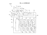
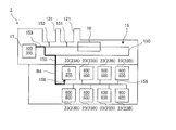
- FIG. 1A is a schematic view showing the internal structure of the paper leaf processing apparatus 1.
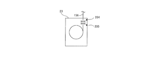
- FIG. 1B is a schematic view showing the first sensor 234 and the second sensor 235 of the first take-up type storage unit 23.
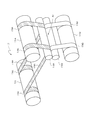
- FIG. 2 is a perspective view showing the temporary holding portion 17.
- FIG. 3 is a perspective view showing the first retractable storage unit 23.
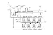
- FIG. 4 is a block diagram showing a configuration of a paper leaf processing apparatus. In FIG. 1A, the left side is the front side of the paper leaf processing apparatus 1, and the right side is the rear side.
- the paper leaf processing device 1 shown in FIG. 1A is a banknote deposit / withdrawal machine for depositing / withdrawing banknotes as paper leaves.
- the paper leaf processing apparatus 1 includes a processing unit 10 and a storage 20 provided below the processing unit 10. The processing unit 10 can be pulled out forward with respect to the storage 20.
- the processing unit 10 has an upper housing 11. In front of the upper housing 11, that is, in front of the processing unit 10, a deposit opening (opening) 121 which is an example of the entrance portion of the present invention and a withdrawal port (opening) 131 which is an example of the exit portion of the present invention. And are provided. In the upper housing 11, that is, in the processing unit 10, the transport unit 15, the identification unit 16 which is an example of the detection unit of the present invention, the temporary holding unit 17 which is an example of the third storage unit of the present invention, and the control unit 18 Is placed.
- a bill feeding mechanism (not shown) is arranged in the vicinity of the deposit opening portion 121 to feed the bills one by one to the transport portion 15 at a predetermined cycle.
- the deposit portion 12 is configured by the deposit port portion 121 and the bill feeding mechanism.
- a collection mechanism (not shown) for stacking banknotes is arranged near the withdrawal port 131.
- the withdrawal unit 13 is composed of the withdrawal port 131 and the accumulation mechanism. If necessary, a second withdrawal unit 14 having the same configuration as the withdrawal unit 13 may be provided next to the withdrawal unit 13. Further, the second withdrawal unit 14 may have a different configuration from the withdrawal unit 13.
- a deposit / withdrawal port which is an example of the entrance / exit portion of the present invention in which both deposits and withdrawals of banknotes are performed, is provided, and a bill feeding mechanism and a collection mechanism are arranged around the deposit / withdrawal port.
- a deposit / withdrawal section may be provided depending on the above.
- the transport unit 15 transports banknotes at a predetermined transport speed.
- the transport unit 15 is composed of a belt mechanism or a roller mechanism for transporting banknotes.
- the transport unit 15 has a loop-shaped transport path 150 capable of transporting banknotes in one direction and a direction opposite to the one direction, and a first branch path 151 and a second branch path 152 branching from the loop-shaped transport path 150.
- the first branch path 151 to the fourth branch path 154 connect the loop-shaped transport path 150, the deposit section 12, the withdrawal section 13, the temporary hold section 17, and the multipurpose storage section 22, which will be described later, respectively.
- the fifth branch path 155 and the sixth branch path 156 connect the loop-shaped transport path 150 and the first take-up type storage unit 23, which will be described later.
- the identification unit 16 includes sensors such as an image sensor, an optical sensor, and a magnetic sensor, and detects the number of banknotes transported by the transport unit 15 and identifies authenticity, denomination, positive loss, and the like. ..
- the temporary holding unit 17 temporarily stores banknotes.
- the temporary holding unit 17 takes in and stores banknotes one by one, and pays out the stored banknotes one by one.
- the temporary holding unit 17 is composed of a retractable storage unit in which a plurality of banknotes are stored in a state of being wound around a rotating body.
- the temporary holding unit 17 includes second reels 171A and 171B, second rollers 172A and 172B, a second drum 173, and two second tapes 174A and 174B.
- One ends of the two second tapes 174A are connected to the second reel 171A by a predetermined distance.
- the second reel 171B is arranged so that its rotation axis is parallel to the rotation axis of the second reel 171A.
- One ends of the two second tapes 174B are connected to the second reel 171B at the same distance as the second tape 174A.
- the second rollers 172A and 172B are arranged so that their rotation axes are parallel to the rotation axes of the second reels 171A and 171B.
- the second rollers 172A and 172B are arranged so as to sandwich the two second tapes 174A drawn from the second reel 171A and the two second tapes 174B drawn from the second reel 171B in an overlapping manner. Has been done.
- the second drum 173 is arranged so that its rotation axis is parallel to the rotation axes of the second reels 171A and 171B and the second rollers 172A and 172B.
- the other ends of the second tapes 174A and 174B are connected to the second drum 173.
- the banknotes conveyed in the third branch path 153 are inserted between the second tape 174A drawn from the second reel 171A and the second tape 174B drawn from the second reel 171B, as shown by arrow A1. Will be done.
- the bills inserted in this way are wound up on the second drum 173 together with the second tapes 174A and 174B by the rotation of the second reels 171A and 171B and the second drum 173.
- the banknotes wound around the second drum 173 are discharged from the second drum 173 by the rotation of the second reels 171A and 171B and the second drum 173, and are fed out to the third branch path 153.
- the second reel 171A and the second roller 172A are each divided into two at predetermined positions along the rotation axis, and the second reel 171A of 1 and the second roller 172A of 1 provide the second tape 174A of 1. It may be moved and the other second tape 174A may be moved by the other second reel 171A and the other second roller 172A. The same applies to the second reel 171B and the second roller 172B. Further, the number of the second tapes 174A and 174B constituting the temporary holding unit 17 may be one or three or more, respectively. Further, the second rollers 172A and 172B may not be provided. Further, the temporary holding unit 17 may be configured as a laminated storage unit in which a plurality of banknotes are stored in a laminated state, or may be the same as the configuration described later of the first winding type storage unit 23. Good.
- the storage 20 can be composed of, for example, a safe, and forms the lower housing 21.
- a lockable storage door (not shown) is provided in front of or behind the lower housing 21.
- one multipurpose storage unit 22 and eight first retractable storage units 23 are arranged in this order from the front.
- the multipurpose storage unit 22 is a laminated storage unit in which a plurality of banknotes are stored in a laminated state.
- the multipurpose storage unit 22 is a bill storage unit that can be used for various purposes, and is used for storing, for example, overflow bills, withdrawal reject bills, forgotten bills, fake bills, and suspicious bills.
- the overflow bill is a bill that cannot be stored in the storage unit because the storage unit (first retractable storage unit 23) to store the overflow bill is full.
- the withdrawal rejected banknote is normally identified by the identification unit 16 due to a transport abnormality such as skewing among the banknotes unwound from the first take-up type storage unit 23 when the withdrawal process of the banknote is performed. It is a banknote that could not be made.
- the forgotten banknote is a banknote that has been withdrawn to the withdrawal unit 13 and then the predetermined time has passed without being taken out from the withdrawal unit 13.
- a stacking table (not shown) that moves up and down according to the amount of banknotes to be stored is arranged inside the multipurpose storage unit 22 .
- the multipurpose storage unit 22 can stack and store the banknotes transported via the fourth branch road 154 on the stacking table, and pay out the banknotes stacked on the stacking table one by one to the fourth branch road 154. It is configured so that it can be done.
- a sixth branch path 156 branching from the fifth branch path 155 is connected to each of the eight first take-up storage units 23.
- the eight first take-up type storage units 23 store a specific type of banknote among the banknotes classified according to authenticity, positive loss, denomination, and the like.
- the eight first retractable storage units 23 may store bills of different types from each other. Further, at least two first take-up type storage units 23 may store the same type of banknotes.
- the first take-up type storage unit 23 takes in and stores banknotes one by one, and pays out the stored banknotes one by one.
- the eight first retractable storage units 23 are composed of a common unit, and the maximum number of bills that can be stored is set to be the same.
- the eight first take-up storage units 23 are configured such that the maximum number of storage units is larger than the maximum number of storage units of the temporary holding unit 17. As shown in FIG. 3, the first take-up type storage unit 23 includes a first reel 231, a first drum 232, and two first tapes 233.
- One ends of the two first tapes 233 are connected to the first reel 231 by a predetermined distance.
- the rotation axis of the first drum 232 is arranged so as to be parallel to the rotation axis of the first reel 231.
- the other end of the first tape 233 is connected to the first drum 232.
- the banknotes conveyed in the sixth branch road 156 are wound on the first tape 233 and the first drum 232 before being drawn out from the first reel 231 and wound on the first drum 232. It is inserted between the first tape 233 on the outermost circumference that has been turned. The bills inserted in this way are wound up on the first drum 232 together with the first tape 233 by the rotation of the first reel 231 and the first drum 232. Further, the banknotes wound around the first drum 232 are discharged from the first drum 232 by the rotation of the first reel 231 and the first drum 232, and are delivered to the sixth branch path 156.
- the number of the first tape 233 constituting the first take-up type storage unit 23 may be one or three or more. Further, the first take-up type storage unit 23 may be configured as a laminated type storage unit in which a plurality of banknotes are stored in a laminated state, or may be the same as the configuration of the temporary holding unit 17.
- the control unit 18 has at least a CPU (Central Processing Unit) and a memory. As shown in FIG. 4, the control unit 18 can transmit and receive signals to the deposit unit 12, the withdrawal unit 13, the transport unit 15, the temporary hold unit 17, the multipurpose storage unit 22, and the first retractable storage unit 23. It is connected to the.
- the deposit unit 12, the withdrawal unit 13, the transport unit 15, the temporary hold unit 17, the multipurpose storage unit 22, and the first retractable storage unit 23 include a sensor (not shown) for detecting banknotes being transported. ..
- each first take-up type storage unit 23 is provided with a first sensor 234 and a second sensor 235 arranged in the bill transport direction.
- the control unit 18 can recognize the banknote transport direction based on the difference in the banknote detection timing between the first sensor 234 and the second sensor 235 arranged in this way. When the detection signals of these sensors are input, the control unit 18 outputs a control signal based on the detection signals, and the deposit unit 12, the withdrawal unit 13, the temporary hold unit 17, and the multipurpose unit 18 via the transport unit 15. Each unit constituting the paper leaf processing device 1 is controlled so that banknotes are transported between the storage unit 22 and the first take-up type storage unit 23. Further, the identification unit 16, the display unit 31, the operation unit 32, the communication unit 33, and the storage unit 34 are connected to the control unit 18.
- the display unit 31 is composed of, for example, a flat panel display and displays various information.
- the paper leaf processing device 1 transmits and receives signals to and from a host terminal (not shown) and other devices (not shown) via, for example, a LAN (Local Area Network) or a serious bus. ..
- the storage unit 34 is composed of, for example, a general-purpose storage device such as a hard disk drive or a flash memory.
- the storage unit 34 stores at least the number of denominations among the number of denominations of banknotes stored in the paper leaf processing device 1 and the amount of money of the banknotes.
- the storage unit 34 stores at least the number of denominations among the number of denominations of banknotes and the amount of money in the banknotes, for example, in units of storage units.
- the storage unit 34 stores the height of each of the multipurpose storage unit 22 and the first retractable storage unit 23.
- the storage unit 34 stores a serial number list in which the serial numbers of the banknotes stored in the multipurpose storage unit 22 and the first retractable storage unit 23 are associated with the serial numbers corresponding to the number of stored bills. The serial numbers in this serial number list are arranged in the order in which the banknotes are stored in the multipurpose storage unit 22 and the first retractable storage unit 23.
- the storage unit 34 stores the history of various processes executed in the paper leaf processing
- the deposit processing is a process of identifying the banknotes drawn out from the deposit unit 12 and storing the normally identified banknotes (normal banknotes) in the paper leaf processing device 1.
- the operator inserts the banknote into the deposit slot 121, and inputs the deposit processing start command to the paper leaf processing device 1 by operating the host terminal or the operation unit 32.
- the bills in the deposit port 121 are fed one by one by the bill feeding mechanism of the deposit unit 12, and then transported to the identification unit 16 by the transport unit 15.
- the identification unit 16 identifies and counts the banknotes.
- the transport unit 15 stores the normal banknotes in the temporary holding unit 17 by the loop-shaped transport path 150 and the third branch path 153.
- the transport unit 15 uses the loop-shaped transport path 150 and the second branch path 152 to connect the rejected banknotes, which are the banknotes that could not be normally identified among the banknotes processed by the identification unit 16, to the withdrawal port 131. Transport.
- the upper terminal or the display unit 31 displays the counting result. After confirming the counting result, the operator performs a predetermined storage operation on the host terminal or the operation unit 32. By this storage operation, the temporary holding unit 17 pays out the banknotes stored therein one by one.
- the transport unit 15 identifies each of the drawn banknotes by the identification unit 16, and based on the storage allocation set in advance, the third branch path 153, the loop-shaped transport path 150, the fifth branch path 155, and the transfer unit 15. It is stored in the predetermined first take-up type storage unit 23 by the sixth branch road 156.
- the transport unit 15 pays out the banknotes stored in the temporary holding unit 17 to the withdrawal port 131.
- the control unit 18 updates the current amount, serial number list, etc. stored in the storage unit 34.
- normal banknotes are temporarily stored in the temporary holding unit 17 and then stored in the predetermined first take-up type storage unit 23.
- the normal banknotes may be stored in the predetermined first take-up type storage unit 23 without using the temporary holding unit 17 (without passing through).
- the withdrawal process is a process of paying out the banknotes stored in the paper leaf processing device 1.
- the operator inputs a withdrawal processing start command for specifying the denomination and the number of sheets to the paper leaf processing device 1 by operating the host terminal or the operation unit 32.
- the first take-up type storage unit 23 that stores the bills of the designated denomination pays out the stored bills by the designated number.
- the transport unit 15 transports the drawn banknotes to the identification unit 16 by the sixth branch path 156, the fifth branch path 155, and the loop-shaped transport path 150.
- the transport unit 15 pays out the banknotes identified by the identification unit 16 to the withdrawal port 131 through the loop-shaped transport path 150 and the second branch path 152.
- the control unit 18 updates the current amount, serial number list, etc. stored in the storage unit 34.
- the scrutiny process is a process for scrutinizing all banknotes stored in at least one of the multipurpose storage unit 22 and the first retractable storage unit 23.
- the scrutiny process is performed, for example, when an error occurs during the deposit process or when the storage door of the storage 20 is opened or closed.
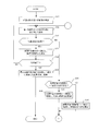
- FIG. 5 is a flowchart of the scrutiny process.
- 6A to 6E are operation explanatory views of the scrutiny process.
- the details of the scrutiny include identification of the number of banknotes, the denomination, and the serial number, but at least the number of banknotes may be detected. Further, in FIGS.
- the number below the horizontal line indicates the maximum number of stored sheets, and the number above is already stored.
- the number of banknotes For example, FIG. 6A shows that the maximum number of sheets of the temporary holding unit 17 is 300, and the maximum number of sheets of all the first retractable storage units 23 is 600. Further, in FIG. 6A, the number of storage sheets of the temporary holding unit 17 is 0, the number of storage sheets of the two upper and lower first winding type storage units 23 at the left end is 600 sheets, and the other storage units of the first winding type storage unit 23 are stored. Indicates that the number of sheets is 550.
- the number of sheets of paper that can be stored in the temporary holding unit 17 (hereinafter referred to as "the number of storage capacity") is 300, and the number of storage capacity of the two leftmost first retractable storage units 23 is 0. It is shown that the storage capacity of each of the other six first retractable storage units 23 is 50.
- the banknotes stored in the first retractable storage unit 23 on the upper left side are scrutinized.
- the first retractable storage unit 23A the first retractable storage unit 23 to be scrutinized on the upper left side
- the first retractable storage unit 23 other than the first storage unit 23A is referred to as the second storage unit 23B.
- Table 1 shows the configurations corresponding to the first storage unit, the second storage unit, and the third storage unit of the present invention in the first embodiment, respectively.
- the control unit 18 When the control unit 18 examines the first storage unit 23A, as shown in FIG. 5, the control unit 18 first causes the identification unit 16 to identify some of the banknotes in the first storage unit 23A, and then causes the identification unit 16 to identify a part of the banknotes, and then causes the third storage unit (hereinafter, , Each part of the paper leaf processing apparatus 1 is controlled so as to be temporarily stored in the "temporary holding part 17" in the description of the present scrutiny process (S1). At this time, the control unit 18 recognizes the number of remaining storage capacity of each of the temporary holding unit 17 and the total second storage unit 23B based on the information stored in the storage unit 34.
- the first The first storage unit 23A pays out the bills so that the number of bills remaining in the first storage unit 23A is equal to or less than the total storage capacity of all the second storage units 23B.
- the temporary holding unit 17 has a storage capacity of 300
- the first storage unit 23A has 600 bills
- the total second storage unit 23B has a total storage capacity of 300.
- the first storage unit 23A pays out 300 banknotes. Then, as shown by the arrow B1 in FIG.
- the transport unit 15 temporarily holds the drawn banknotes by the sixth branch path 156, the fifth branch path 155, the loop-shaped transfer path 150, and the third branch path 153. Temporarily store in part 17.
- the control unit 18 updates the serial number list of the storage unit 34 and the like during or after the bills are temporarily stored in the temporary holding unit 17. By the above processing, the number of bills stored in the temporary holding unit 17, the first storage unit 23A, and the second storage unit 23B is as shown in FIG. 6B.
- the transport unit 15 temporarily stores the bills temporarily stored in the temporary holding unit 17 in the second storage unit 23B (S2).
- the transport unit 15 may preferentially store the banknotes drawn out from the temporary hold unit 17 in the second storage unit 23B located on the upstream side (left side in FIG. 6B) of the banknote transport at the time of storage. ..
- the transport unit 15 may store the banknotes only in the one or two second storage units 23B, instead of distributing the bills in the six second storage units 23B.
- the second storage section 23B located on the upstream side of the banknote transport means the second storage section 23B having a shorter banknote transport path from the temporary holding section 17.
- the transport unit 15 may preferentially store the banknotes drawn out from the temporary hold unit 17 in the second storage unit 23B having a large storage capacity. For example, even if bills can be stored in the six second storage units 23B, all the bills in the temporary holding unit 17 can be stored in one or two second storage units 23B having a large storage capacity. In this case, the transport unit 15 may store the banknotes only in the one or two second storage units 23B instead of distributing the bills in the six second storage units 23B. With such a configuration, the number of second storage units 23B used for storing bills can be reduced. Therefore, the number of times of switching from the fifth branch road 155 to the sixth branch road 156 at the time of storing banknotes can be reduced, and the risk of jamming or the like at the time of switching can be reduced.
- the transport unit 15 may store the banknotes drawn out from the temporary holding unit 17 in all the second storage units 23B that can store the banknotes. At this time, the transport unit 15 may be stored so that the number of sheets temporarily stored in each of the second storage units 23B is the same as each other, or the number of sheets of each second storage unit 23B after temporary storage may be stored. May be stored so that they are the same as each other.
- the transport unit 15 puts 300 banknotes of the temporary holding unit 17 into the third branch path 153, the loop-shaped transport path 150, and the fifth branch path.
- 155 and the sixth branch road 156 50 sheets are temporarily stored in each of the six second storage portions 23B.
- the control unit 18 updates the serial number list of the storage unit 34 and the like during or after the bills are temporarily stored in the second storage unit 23B.
- the distance between the first stored banknote among the temporarily stored banknotes and the last stored banknote among the banknotes stored in the second storage unit 23B before the temporary storage is temporarily stored.
- the distance between the bills may be larger than the distance between the bills stored in the second storage portion 23B before the temporary storage.
- the identification process in the identification unit 16 may be performed.
- the control unit 18 causes the identification unit 16 to identify the remaining banknotes of the first storage unit 23A, and the paper leaf processing device is temporarily stored in the temporary holding unit 17.
- Each part of 1 is controlled (S3).
- the transport unit 15 transports 300 banknotes unwound from the first storage unit 23A into the sixth branch path 156, the fifth branch path 155, and the loop shape. It is stored in the temporary holding portion 17 by the road 150 and the third branch road 153.
- the control unit 18 updates the serial number list of the storage unit 34 and the like during or after the bills are temporarily stored in the temporary holding unit 17.
- the number of bills stored in the temporary holding unit 17, the first storage unit 23A, and the second storage unit 23B is as shown in FIG. 6D.
- the transport unit 15 returns the bills temporarily stored in the temporary holding unit 17 to the first storage unit 23A (S4).
- the transport unit 15 transfers the banknotes of the temporary holding unit 17 to the third branch path 153, the loop-shaped transport path 150, the fifth branch path 155, and the sixth branch path.
- the control unit 18 updates the serial number list of the storage unit 34 and the like during or after returning the bills to the first storage unit 23A.
- the number of banknotes stored in the temporary holding unit 17, the first storage unit 23A, and the second storage unit 23B is as shown in FIG. 6E.
- the identification process in the identification unit 16 may be performed.
- the transport unit 15 returns the bills temporarily stored in the second storage unit 23B to the first storage unit 23A (S5).
- the transport unit 15 returns the banknotes of the first storage unit 23A to the first storage unit 23A by the sixth branch path 156 and the fifth branch path 155, for example, as shown by the arrow B5 in FIG. 6E.
- the control unit 18 updates the serial number list of the storage unit 34 and the like during or after returning the bills to the first storage unit 23A.
- the banknotes are placed on both sides of the banknotes by the second tape 174A and the second tape 174B, respectively. It can be transported while sandwiching it. Therefore, it is possible to reliably wind the banknotes on the second drum 173.
- the first storage unit 23A and the second storage unit 23B since the bill is wound by being overlapped with the first tape located on one side of the bill by the first drum 232, the bill is located on both sides of the bill.
- the thickness of the wound object can be reduced as compared with a configuration such as the temporary holding portion 17 for winding the banknote together with the tape. Therefore, the maximum number of sheets that can be stored can be increased without increasing the arrangement space of the first storage unit 23A and the second storage unit 23B.
- the denomination and the number of banknotes are identified as the scrutiny process, the number of banknotes stored in the first storage unit 23A, the serial number list, the amount of money, etc. can be secured.
- first storage unit 23A and the second storage unit 23B are stored in the storage 20 composed of a safe, and the identification unit 16 and the temporary holding unit 17 are arranged outside the storage 20. It is possible to reduce the size of the paper leaf processing apparatus 1 having a general structure.
- the paper leaf processing device 1A of the second embodiment is different in the configuration of the deposit unit 12 and the withdrawal unit 13 from the paper leaf processing device 1 of the first embodiment.
- the deposit unit 12 includes a deposit shutter 122 indicated by a chain double-dashed line in addition to the configuration of the first embodiment.
- the deposit shutter 122 opens and closes the deposit port 121 by sliding near the opening of the deposit port 121.
- the withdrawal unit 13 includes a withdrawal shutter 132 indicated by a chain double-dashed line and a retract mechanism (not shown) in addition to the configuration of the first embodiment.
- the withdrawal shutter 132 opens and closes the withdrawal port 131 by sliding near the opening of the withdrawal port 131.
- the retract mechanism takes in the banknotes of the withdrawal port 131 into the second branch path 152.
- the scrutiny process of the second embodiment is performed based on the flowchart of FIG. 5 in the first embodiment.
- the deposit shutter 122 and the withdrawal shutter 132 are used for scrutinizing the first storage section (hereinafter, referred to as "first retractable storage section 23 on the upper left side” in the description of this scrutiny process).
- the deposit port 121 and the withdrawal port 131 are closed.
- the control unit 18 causes the identification unit 16 to identify a part of the banknotes of the first take-up type storage unit 23 on the upper left side, and the third storage unit (hereinafter, “temporary holding unit” in the description of this scrutiny process.
- Each part of the paper sheet processing apparatus 1A is controlled so as to be temporarily stored in (17) (S1).
- the transport unit 15 refers to the bills temporarily stored in the temporary holding unit 17 as the second storage unit (hereinafter, "at least one of the deposit port 121 and the withdrawal port 131" in the description of this scrutiny process. " Temporarily store in (say) (S2). After that, the control unit 18 causes the identification unit 16 to identify the remaining banknotes of the first take-up type storage unit 23 on the upper left side, and temporarily stores the remaining bills in the temporary holding unit 17 of the paper leaf processing device 1. Each part is controlled (S3). After that, the transport unit 15 returns the bills temporarily stored in the temporary holding unit 17 to the first take-up type storage unit 23 on the upper left side (S4). Then, the transport unit 15 returns the banknotes temporarily stored in at least one of the deposit port 121 and the withdrawal port 131 to the first take-up storage unit 23 on the upper left side (S5). The scrutiny process is completed by the above process.
- the deposit port 121 and the withdrawal port 131 generally provided in the paper leaf processing apparatus 1A can be effectively used as a second storage unit for temporarily storing banknotes during the close examination process.
- FIG. 7 is a schematic view showing the internal structure of the paper leaf processing apparatus 1B.
- the same configuration as the paper leaf processing apparatus 1 of the first embodiment will be described with the same name and the same reference numeral.
- the paper leaf processing device 1B shown in FIG. 7 is different from the paper leaf processing device 1 of the first embodiment in the configuration of the transport unit 15 and the configuration in the storage 20.
- the transport unit 15 includes the first branch road 151 to the third branch road 153, the fifth branch road 155, the sixth branch road 156, the seventh branch road 157, the eighth branch road 158, the ninth branch road 159, and the tenth branch. It has a road 160.
- first laminated storage units 24 In the storage 20, in order from the front, there are two first laminated storage units 24, one second retractable storage unit 25, six first retractable storage units 23, and a second laminated storage unit.
- One storage unit 26 is arranged.
- the upper first laminated storage unit 24 is connected to the loop-shaped transport path 150 via the seventh branch path 157.
- the lower first laminated storage unit 24 is provided with a loop-shaped transport path 150 via an eighth branch path 158 branching from the fifth branch path 155 and a ninth branch path 159 branching from the eighth branch path 158. It is connected to the.
- the first stacked storage unit 24 is configured in the same manner as the multipurpose storage unit 22 of the first embodiment, in which banknotes are stacked and stored on a stacking table, and the banknotes stacked on the stacking table are stacked one by one from the top. It is configured so that it can be extended to the 7th branch road 157 or the 9th branch road 159.
- a first laminated storage unit 24 having two storage compartments along the vertical direction may be provided.
- the seventh branch road 157 is connected to the upper storage compartment
- the ninth branch road 159 is connected to the lower storage compartment.
- the second take-up type storage unit 25 is connected to the loop-shaped transport path 150 via the eighth branch path 158 and the fifth branch path 155.
- the second retractable storage unit 25 is configured to wind and store banknotes.
- the second retractable storage unit 25 is configured such that the maximum number of sheets that can be stored is smaller than the maximum number of sheets that can be stored in the first retractable storage unit 23.
- the second take-up type storage section 25 may have a configuration in which two tapes and a bill sandwiched between the tapes are stacked and wound like the temporary holding section 17, or the first take-up type storage section 25 may be wound.
- the banknote may be wound by overlapping with the tape located on one side of the banknote.
- the second laminated storage unit 26 is connected to a tenth branch path 160 that branches from the loop-shaped transfer path 150.
- the second laminated storage unit 26 is configured so that the maximum number of storage units is larger than the maximum number of storage units of the first laminated storage unit 24.
- the second laminated storage unit 26 is configured in the same manner as the first laminated storage unit 24, and bills are stacked and stored on the stacking table, and the bills stacked on the stacking stand are stacked one by one from the top on the tenth branch road. It is configured so that it can be extended to 160.
- Each of the first laminated storage unit 24, the second retractable storage unit 25, and the second laminated storage unit 26 includes a sensor (not shown) for detecting a bill being transported.
- the control unit 18 When the detection signals of these sensors are input, the control unit 18 outputs a control signal based on the detection signals, and via the transport unit 15, the deposit unit 12, the withdrawal unit 13, the temporary hold unit 17, and the first
- the paper leaf processing device 1B is provided so that the banknotes are transported between the 1-winding storage unit 23, the 1st laminated storage unit 24, the 2nd retractable storage unit 25, and the 2nd laminated storage unit 26. Control each component.
- Table 3 shows the configurations corresponding to the first storage unit, the second storage unit, and the third storage unit of the present invention in the third embodiment, respectively.
- the transport unit 15 stores the bills temporarily stored in the temporary holding unit 17 in the second storage unit (hereinafter, in the description of this scrutiny process, “all first take-up type storage unit 23, all first laminated type storage”.
- the control unit 18 controls each unit of the paper leaf processing device 1B so that the remaining banknotes of the second laminated storage unit 26 are identified by the identification unit 16 and temporarily stored in the temporary holding unit 17. (S3).
- the transport unit 15 returns the banknotes temporarily stored in the temporary holding unit 17 to the second laminated storage unit 26 (S4).
- the transport unit 15 temporarily stores the banknotes temporarily stored in at least one of the first retractable storage unit 23, the first laminated storage unit 24, and the second retractable storage unit 25. Return to the second laminated storage unit 26 (S5).
- the scrutiny process is completed by the above process.
- the second stacking section is used.
- the banknotes of the type storage unit 26 are temporarily stored in the first retractable storage unit 23, the first laminated storage unit 24, the second retractable storage unit 25, and the temporary holding unit 17, respectively, so that the second stacking is performed. It is possible to carry out scrutiny processing of all banknotes in the formula storage unit 26. Therefore, the space for arranging the temporary holding portion 17 can be reduced, and the paper leaf processing apparatus 1B can be miniaturized.
- the fourth embodiment of the present invention is the third embodiment in that the paper leaf processing device 1B is used. However, the temporary storage location for the bills is different from that of the third embodiment.
- Table 4 shows the configurations corresponding to the first storage unit, the second storage unit, and the third storage unit of the present invention in the fourth embodiment, respectively. In the fourth embodiment, the case where the upper first laminated storage unit 24 is applied as the third storage unit of the present invention is illustrated, but the lower first laminated storage unit 24 is applied. You may.
- the control unit 18 is the second laminated storage unit 26.
- a part of the banknotes is identified by the identification unit 16 and temporarily stored in the third storage unit (hereinafter, referred to as "upper first laminated storage unit 24" in the description of this scrutiny process).
- Each part of the leaf processing apparatus 1B is controlled (S1).
- the transport unit 15 stores the banknotes temporarily stored in the upper first laminated storage unit 24 into the second storage unit (hereinafter, in the description of this scrutiny process, “temporary holding unit 17, all first winding type”.
- the control unit 18 causes the identification unit 16 to identify the remaining banknotes in the second laminated storage unit 26, and temporarily stores the remaining banknotes in the upper first laminated storage unit 24. Each part of is controlled (S3).
- the transport unit 15 returns the banknotes temporarily stored in the upper first laminated storage unit 24 to the second laminated storage unit 26 (S4).
- the transport unit 15 is a second stacking type in which banknotes temporarily stored in at least one of the temporary holding unit 17, the all first retractable storage unit 23, and the second retractable storage unit 25 are stacked. Return to the storage unit 26 (S5).
- the scrutiny process is completed by the above process.
- one first laminated storage unit 24 having a maximum number of stored sheets smaller than that of the second laminated storage unit 26 is used.
- the banknotes of the second laminated storage unit 26 are temporarily stored in the temporary holding unit 17, the first retractable storage unit 23, one first laminated storage unit 24, and the second retractable storage unit 25, respectively. By doing so, it is possible to carry out scrutiny processing of all the banknotes of the second laminated storage unit 26. Therefore, the arrangement space of the first laminated storage unit 24 can be reduced, and the paper leaf processing device 1B can be downsized.
- the fifth embodiment of the present invention is a third embodiment in that the paper leaf processing apparatus 1B is used. However, the temporary storage location for the bills is different from that of the third embodiment.
- Table 5 shows the configurations corresponding to the first storage unit, the second storage unit, and the third storage unit of the present invention in the fifth embodiment, respectively.
- the control unit 18 is on the upper left side.
- a part of the banknotes of the first take-up type storage unit 23 is identified by the identification unit 16 and temporarily stored in the third storage unit (hereinafter, referred to as "temporary holding unit 17" in the description of this scrutiny process).
- Each part of the paper sheet processing apparatus 1B is controlled so as to (S1).
- the transport unit 15 stores the banknotes temporarily stored in the temporary holding unit 17 in the second storage unit (hereinafter, in the description of this scrutiny process, “all first laminated storage unit 24, second winding type storage”.
- the control unit 18 causes the identification unit 16 to identify the remaining banknotes of the first take-up type storage unit 23 on the upper left side, and temporarily stores the bills in the temporary holding unit 17 of the paper leaf processing device 1B. Each part is controlled (S3).
- the transport unit 15 returns the bills temporarily stored in the temporary holding unit 17 to the first take-up type storage unit 23 on the upper left side (S4).
- the transport unit 15 holds the bills temporarily stored in at least one of the first laminated storage unit 24, the second retractable storage unit 25, and the second laminated storage unit 26 on the upper left side. Return to the first retractable storage unit 23 (S5).
- the scrutiny process is completed by the above process.
- the sixth embodiment of the present invention is the third embodiment in that the paper leaf processing apparatus 1B is used.
- the temporary storage location for the bills is different from that of the third embodiment.
- as the scrutiny process only the number of sheets is detected using the sensor of the second retractable storage unit 25 without identifying the denomination using the identification unit 16.
- the sensor of the second take-up type storage unit 25 for example, the same configuration as the first sensor 234 and the second sensor 235 shown in FIG. 1B may be applied.
- Table 6 shows the configurations corresponding to the first storage unit, the second storage unit, and the third storage unit of the present invention in the sixth embodiment, respectively.
- the control unit 18 When scrutinizing the first storage unit (hereinafter referred to as “the first retractable storage unit 23 on the upper left side” in the description of this scrutiny process), the control unit 18 is the first retractable storage unit on the upper left side. Paper so that some of the banknotes of 23 are temporarily stored in the third storage unit (hereinafter referred to as “second retractable storage unit 25" in the description of this scrutiny process) without being taken out of the storage 20. It controls each part of the leaf processing apparatus 1B.
- the sensor which is an example of the detection unit of the present invention of the second take-up type storage unit 25 detects the number of stored banknotes and outputs the detection signal to the control unit 18.
- the control unit 18 stores the number of stored sheets of the second retractable storage unit 25 stored in the storage unit 34 based on the detection signal from the second retractable storage unit 25 during or after the temporary storage. Update.
- the transport unit 15 does not take out the banknotes temporarily stored in the second take-up type storage unit 25 from the storage 20, but the second storage unit (hereinafter, "other than the upper left side" in the explanation of this scrutiny process. It is temporarily stored in at least one of the first retractable storage unit 23 and the first laminated storage unit 24 of the above. After that, the transport unit 15 temporarily stores the remaining banknotes of the first take-up type storage unit 23 on the upper left side in the second take-up type storage unit 25 without taking them out of the storage 20.
- the control unit 18 updates the number of stored sheets of the second take-up type storage unit 25 based on the detection signal from the second take-up type storage unit 25.
- the transport unit 15 returns the bills temporarily stored in the second retractable storage unit 25 to the first retractable storage unit 23 on the upper left side without taking them out of the storage 20.
- the transport unit 15 does not take out the banknotes temporarily stored in at least one of the first retractable storage unit 23 and the all first laminated storage unit 24 other than the upper left side from the storage 20. Return to the first retractable storage unit 23 on the upper left side.
- the scrutiny process is completed by the above process.
- the second rewind-type storage unit 25 having a maximum storage number smaller than that of the first rewind-type storage unit 23 having one is stored. Even if it is used, the banknotes of one first retractable storage unit 23 are temporarily stored in the other first retractable storage unit 23, the first laminated storage unit 24, and the second retractable storage unit 25, respectively. By doing so, it is possible to detect the number of all banknotes in the first take-up type storage unit 23. Therefore, the arrangement space of the second take-up type storage unit 25 can be reduced, and the paper leaf processing device 1B can be downsized. Further, the number of sheets detection process can be performed without taking out the banknotes from the storage 20. Further, as compared with the case where the bills are taken out from the storage 20 and the number of bills is detected, the moving distance of the bills can be shortened, so that the risk of jamming of the bills can be reduced.
- the mixed withdrawal process is a process of withdrawing banknotes of a predetermined denomination from one first retractable storage unit 23 in which banknotes of a plurality of denominations are stored.
- FIG. 8 is a flowchart of the mixed withdrawal process.
- the configurations corresponding to the first storage portion, the second storage portion, and the third storage portion of the present invention in the seventh embodiment are as shown in Table 1.
- the operator inputs a withdrawal processing start command for specifying the denomination and the number of sheets to the paper leaf processing device 1 by operating the host terminal or the operation unit 32.
- the control unit 18 issues the denomination and the number of withdrawals to be withdrawn based on the serial number list and denomination of each first retractable storage unit 23 stored in the storage unit 34.
- One first retractable storage unit 23 that can be used for money (hereinafter, referred to as “first retractable storage unit 23 to be withdrawn” in the description of this mixed withdrawal process) is specified as the first storage unit (S11). ).
- control unit 18 pays out one bill from the first take-up type storage unit 23 to be withdrawn, and passes through the sixth branch path 156, the fifth branch path 155, and the loop-shaped transfer path 150. It is conveyed to the identification unit 16 and each unit of the paper leaf processing device 1 is controlled so as to identify the banknote (S12). Then, the control unit 18 determines whether or not the identified banknote is a banknote to be withdrawn (S13).
- the control unit 18 determines that the identified banknote is not a banknote to be withdrawn (S13: NO)
- the control unit 18 refers to the banknote as a third storage unit (hereinafter, "temporary holding unit 17" in the description of the mixed withdrawal process. It is determined whether or not it can be temporarily stored in (S14).
- the transport unit 15 temporarily stores the banknotes in the temporary holding unit 17, and stores the banknotes in the storage unit 34.
- the bill storage status of the first retractable storage unit 23 and the temporary holding unit 17 to be withdrawn is updated (S15).
- the control unit 18 determines that the banknotes cannot be temporarily stored in the temporary holding unit 17 (S14: NO)
- the control unit 18 stores the banknotes in the transport unit 15 in the second storage unit (hereinafter, the description of the mixed withdrawal process).
- the first retractable storage unit 23 that is not subject to withdrawal and the first retractable storage unit 23 that is not subject to withdrawal are temporarily stored in the "first retractable storage unit 23 that is not subject to withdrawal”.
- the bill storage status of the above is updated (S16).
- control unit 18 determines that the banknote identified by the identification unit 16 is a banknote to be withdrawn (S13: YES)
- the control unit 18 causes the transport unit 15 to transport the banknote to the withdrawal port 131 and withdraws.
- the bill storage status of the target first retractable storage unit 23 is updated (S17).
- the control unit 18 determines whether or not to end the withdrawal (S18).
- the control unit 18 performs the process of S12.
- control unit 18 determines that the transfer of all the bills to be withdrawn to the withdrawal port 131 is completed and the withdrawal is completed (S18: YES)
- the control unit 18 controls the transfer unit 15 to withdraw.
- the bills temporarily stored in the first take-up storage unit 23 and the temporary holding unit 17, which are not subject to money, are returned to the first take-up storage unit 23 to be withdrawn (S19). With the above, the mixed withdrawal process is completed.
- the control unit 18 is based on the banknote storage status stored in the storage unit 34. Recognizing the denominations with high withdrawal frequency, the transport unit 15 can preferentially withdraw the banknotes of this recognized denomination at the time of the next mixed withdrawal, so that the banknotes are first wound up for withdrawal. It may be returned to the formula storage unit 23. That is, the denomination with a low withdrawal frequency may be returned to the first take-up type storage unit 23 first, and then the denomination with a high withdrawal frequency may be returned to the first take-up type storage unit 23.
- the concept of preferentially withdrawing denominations with a high withdrawal frequency includes the concept of withdrawing frequently withdrawing denominations first, and the withdrawal frequency first. It also includes the concept of withdrawing several low denomination bills and then withdrawing high frequency denomination bills. With such a configuration, the mixed withdrawal can be completed early. Further, the transport unit 15 returns all the banknotes temporarily stored in the temporary holding unit 17 to the first take-up type storage unit 23 that is not a withdrawal target, and then returns the first take-up type storage unit 23 that is not a withdrawal target. All the bills temporarily stored in the banknote may be returned to the first take-up type storage unit 23 to be withdrawn.
- the transport unit 15 When examining the first retractable storage unit 23 (first storage unit) on the upper left side, the transport unit 15 does not take out all the banknotes in the first storage unit from the storage 20 and stores the first storage unit. It is temporarily stored in the first retractable storage unit 23 (second storage unit) other than the unit. At the time of this storage, the control unit 18 updates the number of stored units of the second storage unit stored in the storage unit 34 based on the detection signals from the first sensor 234 and the second sensor 235 of the second storage unit. After that, the transport unit 15 returns the bills temporarily stored in the second storage unit to the first storage unit without taking them out of the storage 20, and the control unit 18 updates the number of stored bills in the second storage unit. .. The scrutiny process is completed by the above process.
- the number of sheets detection process can be performed without taking out the banknotes from the storage 20.
- the processing of S4 and the processing of S5 may be interchanged.
- at least one of the first retractable storage unit 23 and the all first laminated storage unit 24 other than the upper left side (second storage unit) is temporarily accommodated.
- the banknotes temporarily stored in the second retractable storage unit 25 (third storage unit) are stored. It may be returned to the first take-up type storage part 23 on the upper left side.
- the storage order of the banknotes after the scrutiny process in the first storage unit is different from the storage order before the scrutiny process. Therefore, it is preferable to update the serial number list according to the storage order after the scrutiny process. ..
- the temporary storage destination of the bills in the scrutiny processing of S1 to S5 of FIG. 5 may be as follows. First, the control unit 18 causes the identification unit 16 to identify a part of the banknotes in the first storage unit, and temporarily stores the banknotes in the second storage unit. Next, the control unit 18 temporarily stores the bills temporarily stored in the second storage unit in the third storage unit. After that, the control unit 18 causes the identification unit 16 to identify the remaining banknotes in the first storage unit, and temporarily stores the bills in the second storage unit. After that, the control unit 18 returns the bills temporarily stored in one of the second storage unit and the third storage unit to the first storage unit. Then, the control unit 18 returns the bills temporarily stored in the other of the second storage unit and the third storage unit to the first storage unit.
- the temporary storage destination of banknotes in the scrutiny process may be as follows. First, the control unit 18 temporarily stores some of the banknotes in the first storage unit in the second storage unit without taking them out of the storage 20. Next, the control unit 18 temporarily stores the bills temporarily stored in the second storage unit in the third storage unit without taking them out of the storage 20. After that, the control unit 18 temporarily stores the remaining banknotes in the first storage unit in the second storage unit without taking them out of the storage 20. After that, the control unit 18 returns the bills temporarily stored in one of the second storage unit and the third storage unit to the first storage unit without taking them out of the storage 20. Then, the control unit 18 returns the bills temporarily stored in the other of the second storage unit and the third storage unit to the first storage unit without taking them out of the storage 20.
- the mixed withdrawal process of the seventh embodiment may be performed using the paper leaf processing device 1B shown in FIG. 7.
- the configurations shown in Tables 3 to 6 may be applied as the configurations corresponding to the “first storage portion”, the “second storage portion”, and the “third storage portion” shown in the flowchart of FIG.
- the present invention is useful for a paper leaf processing apparatus that processes paper leaves.
Landscapes
- Physics & Mathematics (AREA)
- General Physics & Mathematics (AREA)
- Engineering & Computer Science (AREA)
- Mechanical Engineering (AREA)
- Pile Receivers (AREA)
Abstract
紙葉類処理装置(1)は、紙葉類を搬送する搬送部(15)と、搬送部(15)により搬送される紙葉類の枚数を検知する識別部(16)と、搬送部(15)により搬送される紙葉類をそれぞれ収納する所定の第1巻き取り式収納部(23)、他の第1巻き取り式収納部(23)及び一時保留部(17)と、制御部(18)と、を備え、一時保留部(17)における紙葉類の最大収納枚数は、前記所定の第1巻き取り式収納部(23)における紙葉類の最大収納枚数よりも少なく、制御部(18)は、前記所定の第1巻き取り式収納部(23)に収納された紙葉類を、他の第1巻き取り式収納部(23)及び一時保留部(17)のそれぞれに一時的に収納するように、搬送部(15)を制御するとともに、紙葉類の搬送中に紙葉類の枚数を検知するように、識別部(16)を制御する。
Description
本発明は、紙葉類処理装置に関する。
従来、紙幣の入金及び出金を行う紙幣処理装置が知られている(例えば、特許文献1参照)。特許文献1には、収納モジュールに収納された全ての紙幣を一旦繰り出し、識別部によって識別及び計数を行い、その紙幣を再び収納モジュールに戻す精査処理が開示されている。特許文献1には、この精査処理において、収納モジュールから繰り出された紙幣の収納先として、他の収納モジュールまたは一時保留部を用いることが開示されている。
しかしながら、特許文献1のような構成では、収納先の収納モジュール又は一時保留部における紙幣の最大収納枚数を、繰り出し元の収納モジュールの最大収納枚数以上にする必要があり、装置の小型化を容易に図れない。
本発明は、小型化を容易に図れる紙葉類処理装置を提供することを目的とする。
本発明の紙葉類処理装置は、紙葉類を搬送する搬送部と、前記搬送部により搬送される紙葉類の枚数を検知する検知部と、前記搬送部により搬送される紙葉類をそれぞれ収納する第1収納部、第2収納部及び第3収納部と、制御部と、を備え、前記第3収納部における前記紙葉類の最大収納枚数は、前記第1収納部における前記紙葉類の最大収納枚数よりも少なく、前記制御部は、前記第1収納部に収納された紙葉類を、前記第2収納部及び前記第3収納部のそれぞれに一時的に収納するように、前記搬送部を制御するとともに、前記紙葉類の搬送中に前記紙葉類の枚数を検知するように、前記検知部を制御する。
本発明によれば、小型化を容易に図れる紙葉類処理装置を提供することができる。
以下、本発明の実施の形態を図面を参照して説明する。本実施の形態では、紙葉類の一例である紙幣の入金及び出金を行う紙葉類処理装置を例示する。紙葉類としては、紙幣に限定されるものではなく、商品券、有価証券、投票用紙等であってもよい。なお、以下の説明において、紙葉類処理装置の「前」とは、紙葉類の投入及び排出の少なくとも一方の操作を処理部に設けられた開口を介して行うオペレータ側を意味し、紙葉類処理装置の「後」とは、その反対側を意味する。言い換えると、紙葉類処理装置の「前」とは、紙葉類の投入及び排出の少なくとも一方の操作を行うための開口が設けられた側を意味する。また、紙葉類処理装置の「左」とは、当該開口に対峙したオペレータから見て左側を意味し、紙葉類処理装置の「右」とは、当該開口に対峙したオペレータからみて右側を意味する。
(1)第1の実施の形態(1-1)紙葉類処理装置の構成
まず、本発明の第1の実施の形態に係る紙葉類処理装置について説明する。図1Aは、紙葉類処理装置1の内部構造を示す模式図である。図1Bは、第1巻き取り式収納部23の第1センサ234及び第2センサ235を示す模式図である。図2は、一時保留部17を示す斜視図である。図3は、第1巻き取り式収納部23を示す斜視図である。図4は、紙葉類処理装置の構成を示すブロック図である。なお、図1Aにおいて、左側が紙葉類処理装置1の前方、右側が同後方である。
まず、本発明の第1の実施の形態に係る紙葉類処理装置について説明する。図1Aは、紙葉類処理装置1の内部構造を示す模式図である。図1Bは、第1巻き取り式収納部23の第1センサ234及び第2センサ235を示す模式図である。図2は、一時保留部17を示す斜視図である。図3は、第1巻き取り式収納部23を示す斜視図である。図4は、紙葉類処理装置の構成を示すブロック図である。なお、図1Aにおいて、左側が紙葉類処理装置1の前方、右側が同後方である。
図1Aに示す紙葉類処理装置1は、紙葉類としての紙幣を入出金する紙幣入出金機である。紙葉類処理装置1は、処理部10及び処理部10の下方に設けられた収納庫20を備えている。処理部10は、収納庫20に対して前方に引き出し可能である。
処理部10は、上部筐体11を有している。上部筐体11の前方、すなわち処理部10の前方には、本発明の入口部の一例である入金口部(開口)121と本発明の出口部の一例である出金口部(開口)131とが設けられている。上部筐体11内、すなわち処理部10内には、搬送部15、本発明の検知部の一例である識別部16、本発明の第3収納部の一例である一時保留部17及び制御部18が配置されている。
入金口部121の近傍には、所定の周期で紙幣を1枚ずつ搬送部15に繰り出す紙幣繰り出し機構(図示略)が配置されている。入金口部121と紙幣繰り出し機構によって、入金部12が構成されている。
出金口部131の近傍には、紙幣を積み重ねる集積機構(図示略)が配置されている。出金口部131と集積機構によって、出金部13が構成されている。必要に応じて、出金部13と同様の構成を有する第2出金部14を、出金部13の隣に設けてもよい。また、第2出金部14は、出金部13と異なる構成であってもよい。
なお、処理部10の前方には、必要に応じて入金部12と出金部13のいずれか一方のみが設けられていてもよい。また、紙幣の入金及び出金の両方が行われる本発明の出入口部の一例である入出金口部が設けられるとともに、この入出金口部の周囲に紙幣繰り出し機構及び集積機構が配置されることによって、入出金部が設けられていてもよい。
搬送部15は、紙幣を所定の搬送速度で搬送する。搬送部15は、紙幣を搬送するベルト機構又はローラ機構によって構成されている。搬送部15は、紙幣を一の方向及び一の方向と反対の方向に搬送可能とするループ状搬送路150と、このループ状搬送路150から分岐する第1分岐路151、第2分岐路152、第3分岐路153、第4分岐路154、第5分岐路155及び第6分岐路156を有している。第1分岐路151~第4分岐路154は、それぞれ、ループ状搬送路150と、入金部12、出金部13、一時保留部17及び後述する多目的収納部22とを接続する。第5分岐路155及び第6分岐路156は、ループ状搬送路150と、後述する第1巻き取り式収納部23とを接続する。
識別部16は、画像センサ、光学センサ、磁気センサ等のセンサを備えており、搬送部15で搬送される紙幣の枚数を検知したり、真偽、金種、正損等を識別したりする。
一時保留部17は、紙幣を一時的に収納する。一時保留部17は、紙幣を1枚ずつ取り込んで収納し、収納している紙幣を1枚ずつ繰り出す。一時保留部17は、図2に示すように、複数の紙幣が回転体に巻き取られた状態で収納される巻き取り式の収納部で構成されている。一時保留部17は、第2リール171A,171Bと、第2ローラ172A,172Bと、第2ドラム173と、2本ずつの第2テープ174A,174Bとを備えている。
第2リール171Aには、2本の第2テープ174Aの一端が所定距離だけ離れて接続されている。第2リール171Bは、その回転軸が第2リール171Aの回転軸と平行になるように配置されている。第2リール171Bには、2本の第2テープ174Bの一端が、第2テープ174Aと同じ距離だけ離れて接続されている。
第2ローラ172A,172Bは、その回転軸が第2リール171A,171Bのそれぞれの回転軸と平行になるように配置されている。第2ローラ172A,172Bは、第2リール171Aから引き出された2本の第2テープ174Aと、第2リール171Bから引き出された2本の第2テープ174Bとを、それぞれ重ねて挟むように配置されている。
第2ドラム173は、その回転軸が第2リール171A,171B、第2ローラ172A,172Bのそれぞれの回転軸と平行になるように配置されている。第2ドラム173には、第2テープ174A,174Bの他端が接続されている。
第3分岐路153で搬送された紙幣は、矢印A1に示すように、第2リール171Aから引き出された第2テープ174Aと、第2リール171Bから引き出された第2テープ174Bとの間に挿入される。このように挿入された紙幣は、第2リール171A,171B及び第2ドラム173の回転によって、第2テープ174A,174Bとともに、第2ドラム173に巻き取られる。また、第2ドラム173に巻き取られた紙幣は、第2リール171A,171B及び第2ドラム173の回転によって、第2ドラム173から放出され、第3分岐路153に繰り出される。
なお、第2リール171A、第2ローラ172Aが、それぞれ、回転軸に沿った所定位置で2つに分割され、1の第2リール171A及び1の第2ローラ172Aにより1の第2テープ174Aを移動させ、他の第2リール171A及び他の第2ローラ172Aにより他の第2テープ174Aを移動させてもよい。第2リール171B、第2ローラ172Bについても同様である。また、一時保留部17を構成する第2テープ174A,174Bは、それぞれ1本であってもよいし、3本以上であってもよい。また、第2ローラ172A,172Bはなくてもよい。さらに、一時保留部17は、複数の紙幣が積層状態で収納される積層式の収納部で構成されていてもよいし、第1巻き取り式収納部23の後述する構成と同じであってもよい。
収納庫20は、例えば金庫で構成することができ、下部筐体21を形成する。下部筐体21の前方又は後方には、施錠可能な収納庫扉(図示略)が設けられている。収納庫20内には、前方から順に、多目的収納部22が1つ、第1巻き取り式収納部23が8つ配置されている。
多目的収納部22は、複数の紙幣が積層状態で収納される積層式の収納部である。多目的収納部22は、様々な目的で使用することができる紙幣収納部であり、例えば、オーバーフロー紙幣、出金リジェクト紙幣、取忘紙幣、偽券、疑券の収納に用いられる。オーバーフロー紙幣とは、それを収納すべき収納部(第1巻き取り式収納部23)が満杯になったために当該収納部に収納できなくなった紙幣である。また、出金リジェクト紙幣とは、紙幣の出金処理が行われる際に第1巻き取り式収納部23から繰り出された紙幣のうち、斜行等の搬送異常により識別部16で正常に識別することができなかった紙幣である。また、取忘紙幣とは、出金部13に一旦出金された後、出金部13から取り出されることなく所定時間が経過した紙幣である。多目的収納部22の内部には、収納される紙幣の量に応じて昇降する集積台(図示略)が配置されている。多目的収納部22は、第4分岐路154を介して搬送された紙幣を集積台で積層して収納し、集積台に積層された紙幣を上から1枚ずつ第4分岐路154に繰り出すことができるように構成されている。
8つの第1巻き取り式収納部23には、第5分岐路155から分岐する第6分岐路156がそれぞれ接続されている。8つの第1巻き取り式収納部23は、真偽、正損、金種等によって分類された紙幣のうちの特定の種類の紙幣を収納する。8つの第1巻き取り式収納部23は、互いに異なる種類の紙幣を収納してもよい。また、少なくとも2つの第1巻き取り式収納部23が、同じ種類の紙幣を収納してもよい。第1巻き取り式収納部23は、紙幣を1枚ずつ取り込んで収納し、収納している紙幣を1枚ずつ繰り出す。8つの第1巻き取り式収納部23は、共通のユニットで構成され、紙幣の最大収納枚数が同じに設定されている。8つの第1巻き取り式収納部23は、その最大収納枚数が一時保留部17の最大収納枚数よりも多くなるように構成されている。第1巻き取り式収納部23は、図3に示すように、第1リール231と、第1ドラム232と、2本の第1テープ233とを備えている。
第1リール231には、2本の第1テープ233の一端が所定距離だけ離れて接続されている。
第1ドラム232は、その回転軸が第1リール231の回転軸と平行になるように配置されている。第1ドラム232には、第1テープ233の他端が接続されている。
第6分岐路156で搬送された紙幣は、矢印A2に示すように、第1リール231から引き出されて第1ドラム232に巻回される前の第1テープ233と、第1ドラム232に巻回された最外周の第1テープ233との間に挿入される。このように挿入された紙幣は、第1リール231及び第1ドラム232の回転によって、第1テープ233とともに、第1ドラム232に巻き取られる。また、第1ドラム232に巻き取られた紙幣は、第1リール231及び第1ドラム232の回転によって、第1ドラム232から放出され、第6分岐路156に繰り出される。
なお、第1巻き取り式収納部23を構成する第1テープ233は、1本であってもよいし、3本以上であってもよい。また、第1巻き取り式収納部23は、複数の紙幣が積層状態で収納される積層式の収納部で構成されていてもよいし、一時保留部17の構成と同じであってもよい。
制御部18は、少なくともCPU(Central Processing Unit)とメモリを備えている。制御部18には、図4に示すように、入金部12、出金部13、搬送部15、一時保留部17、多目的収納部22、第1巻き取り式収納部23が、信号を送受信可能に接続されている。これら入金部12、出金部13、搬送部15、一時保留部17、多目的収納部22、第1巻き取り式収納部23は、搬送中の紙幣を検知するセンサ(図示略)を含んでいる。例えば、各第1巻き取り式収納部23には、図1Bに示すように、紙幣搬送方向に並ぶ第1センサ234と第2センサ235とが設けられている。このように配置された第1センサ234及び第2センサ235における紙幣検出タイミングの差に基づいて、制御部18は紙幣の搬送方向を認識することができる。制御部18は、これらのセンサの検知信号が入力されると、この検知信号に基づき制御信号を出力し、搬送部15を介して、入金部12、出金部13、一時保留部17、多目的収納部22、第1巻き取り式収納部23の間で紙幣が搬送されるように、紙葉類処理装置1を構成する各部を制御する。また、制御部18には、識別部16、表示部31、操作部32、通信部33、記憶部34が接続されている。
表示部31は、例えば、フラットパネルディスプレイで構成され、各種情報を表示する。
操作部32は、紙葉類処理装置1のオペレータに対するヒューマンインターフェース部分として機能する。なお、表示部31をタッチパネル式のディスプレイにより操作部としても機能するように構成することにより、表示部31と操作部32とを一体にしてもよい。
通信部33は、紙葉類処理装置1が、例えばLAN(Local Area Network)やシリアスバスを介して、上位端末(図示略)やその他の機器(図示略)との間で信号の送受信を行う。
記憶部34は、例えば、ハードディスクドライブやフラッシュメモリ等の汎用のストレージデバイスから構成されている。記憶部34は、紙葉類処理装置1に収納された紙幣の金種別枚数及び紙幣の金額である在高のうち、少なくとも金種別枚数を記憶する。記憶部34は、例えば、収納部単位で、紙幣の金種別枚数及び紙幣の金額である在高のうち、少なくとも金種別枚数を記憶する。また、記憶部34は、多目的収納部22、第1巻き取り式収納部23毎の在高を記憶する。記憶部34は、多目的収納部22、第1巻き取り式収納部23に収納されている紙幣の記番号と、その収納枚数に対応する通し番号とを関連づけた記番号リストを記憶する。この記番号リストの記番号は、紙幣が多目的収納部22、第1巻き取り式収納部23に収納された順序で並んでいる。記憶部34は、紙葉類処理装置1において実行された各種処理の履歴をログとして記憶する。
(1-2)紙葉類処理装置の処理
(1-2-1)入金処理
まず、紙葉類処理装置1における処理として、入金処理について説明する。入金処理とは、入金部12から繰り出した紙幣を識別し、正常に識別された紙幣(正常紙幣)を紙葉類処理装置1内に収納する処理である。
(1-2-1)入金処理
まず、紙葉類処理装置1における処理として、入金処理について説明する。入金処理とは、入金部12から繰り出した紙幣を識別し、正常に識別された紙幣(正常紙幣)を紙葉類処理装置1内に収納する処理である。
オペレータは、紙幣を入金口部121に投入し、上位端末や操作部32の操作によって、入金処理の開始コマンドを紙葉類処理装置1に入力する。入金口部121の紙幣は、入金部12の紙幣繰り出し機構によって1枚ずつ繰り出された後、搬送部15によって識別部16に搬送される。識別部16は、その紙幣の識別と計数とを行う。搬送部15は、識別部16で処理された紙幣のうち、正常紙幣を、ループ状搬送路150及び第3分岐路153によって、一時保留部17に収納する。一方、搬送部15は、識別部16で処理された紙幣のうち、正常に識別できなかった紙幣であるリジェクト紙幣を、ループ状搬送路150及び第2分岐路152によって、出金口部131に搬送する。
入金口部121に投入された紙幣が全て繰り出されることによって、入金された全ての紙幣の計数が完了すると、上位端末や表示部31は、計数結果を表示する。オペレータは、その計数結果を確認した上で、上位端末や操作部32において所定の収納操作を行う。この収納操作によって、一時保留部17は、そこに収納している紙幣を一枚ずつ繰り出す。搬送部15は、この繰り出された各紙幣を、識別部16による識別結果、及び、予め設定された収納割当に基づいて、第3分岐路153、ループ状搬送路150、第5分岐路155及び第6分岐路156によって、所定の第1巻き取り式収納部23に収納する。なお、オペレータが、収納操作ではなく、所定のキャンセル操作を行ったときには、搬送部15は、一時保留部17に収納されている紙幣を出金口部131に払い出す。制御部18は、入金処理が終了すると、記憶部34に記憶されている在高、記番号リスト等を更新する。
なお、本(1-2-1)入金処理の項目では、一時保留部17に一旦正常紙幣を収納し、その後所定の第1巻き取り式収納部23に収納する例を示したが、入金処理において、一時保留部17を用いず(経由させず)に正常紙幣を所定の第1巻き取り式収納部23に収納してもよい。
(1-2-2)出金処理
次に、紙葉類処理装置1における出金処理について説明する。出金処理とは、紙葉類処理装置1内に収納されている紙幣を払い出す処理である。
次に、紙葉類処理装置1における出金処理について説明する。出金処理とは、紙葉類処理装置1内に収納されている紙幣を払い出す処理である。
オペレータは、上位端末や操作部32の操作によって、金種と枚数とを指定する出金処理の開始コマンドを紙葉類処理装置1に入力する。指定された金種の紙幣を収納している第1巻き取り式収納部23は、収納している紙幣を指定された枚数だけ繰り出す。そして、搬送部15は、この繰り出した紙幣を、第6分岐路156、第5分岐路155、ループ状搬送路150によって、識別部16に搬送する。搬送部15は、識別部16で識別が行われた紙幣を、ループ状搬送路150及び第2分岐路152によって、出金口部131に払い出す。制御部18は、出金処理が終了すると、記憶部34に記憶されている在高、記番号リスト等を更新する。
(1-2-3)精査処理
次に、紙葉類処理装置1における精査処理について説明する。精査処理とは、多目的収納部22及び第1巻き取り式収納部23のうち少なくとも一方に収納されている全ての紙幣の精査を行う処理である。精査処理は、例えば、入金処理時にエラーが発生した場合や、収納庫20の収納庫扉が開閉された場合に行われる。図5は、精査処理のフローチャートである。図6A~6Eは、精査処理の動作説明図である。なお、精査内容として、紙幣の枚数、金種、記番号の識別を例示するが、少なくとも枚数を検知すればよい。また、図6A~6Eにおいて、一時保留部17及び第1巻き取り式収納部23を示す四角形内の数字のうち、横線の下側の数字は最大収納枚数を示し、上側の数字は収納済みの紙幣の枚数を示す。例えば、図6Aは、一時保留部17の最大収納枚数が300枚であり、全第1巻き取り式収納部23の最大収納枚数が600枚であることを示す。また、図6Aは、一時保留部17の収納枚数が0枚、左端の上下2つの第1巻き取り式収納部23の収納枚数が600枚、それ以外の第1巻き取り式収納部23の収納枚数が550枚であることを示す。つまり、一時保留部17に収納可能な紙葉類の枚数(以下、「収納余力枚数」と言う)が300枚、左端の2つの第1巻き取り式収納部23の収納余力枚数が0枚、それ以外の6つの第1巻き取り式収納部23の収納余力枚数がそれぞれ50枚であることを示す。
次に、紙葉類処理装置1における精査処理について説明する。精査処理とは、多目的収納部22及び第1巻き取り式収納部23のうち少なくとも一方に収納されている全ての紙幣の精査を行う処理である。精査処理は、例えば、入金処理時にエラーが発生した場合や、収納庫20の収納庫扉が開閉された場合に行われる。図5は、精査処理のフローチャートである。図6A~6Eは、精査処理の動作説明図である。なお、精査内容として、紙幣の枚数、金種、記番号の識別を例示するが、少なくとも枚数を検知すればよい。また、図6A~6Eにおいて、一時保留部17及び第1巻き取り式収納部23を示す四角形内の数字のうち、横線の下側の数字は最大収納枚数を示し、上側の数字は収納済みの紙幣の枚数を示す。例えば、図6Aは、一時保留部17の最大収納枚数が300枚であり、全第1巻き取り式収納部23の最大収納枚数が600枚であることを示す。また、図6Aは、一時保留部17の収納枚数が0枚、左端の上下2つの第1巻き取り式収納部23の収納枚数が600枚、それ以外の第1巻き取り式収納部23の収納枚数が550枚であることを示す。つまり、一時保留部17に収納可能な紙葉類の枚数(以下、「収納余力枚数」と言う)が300枚、左端の2つの第1巻き取り式収納部23の収納余力枚数が0枚、それ以外の6つの第1巻き取り式収納部23の収納余力枚数がそれぞれ50枚であることを示す。
第1の実施の形態では、図1A及び図6A~6Eに示す8つの第1巻き取り式収納部23のうち、左上側の第1巻き取り式収納部23に収納されている紙幣の精査について説明する。以下において、左上側の精査対象の第1巻き取り式収納部23を第1収納部23Aと言い、第1収納部23A以外の第1巻き取り式収納部23を第2収納部23Bと言う。表1に、第1の実施の形態における本発明の第1収納部、第2収納部及び第3収納部にそれぞれ対応する構成を示す。

制御部18は、第1収納部23Aの精査を行うに際し、図5に示すように、まず、第1収納部23Aの一部の紙幣を識別部16で識別させて、第3収納部(以下、本精査処理の説明において「一時保留部17」と言う)に一時的に収納するように紙葉類処理装置1の各部を制御する(S1)。このとき、制御部18は、記憶部34に記憶された情報に基づいて、一時保留部17及び全第2収納部23Bそれぞれの収納余力枚数を認識する。次に、制御部18が、一時保留部17の収納余力枚数と全第2収納部23Bの収納余力枚数との和が、第1収納部23Aの紙幣の枚数よりも多いことを認識すると、第1収納部23Aに残る紙幣の枚数が、全第2収納部23Bの合計収納余力枚数以下となるように、第1収納部23Aは紙幣を繰り出す。例えば、図6Aに示すように、一時保留部17の収納余力枚数が300枚、第1収納部23Aの紙幣の枚数が600枚、全第2収納部23Bの合計収納余力枚数が300枚の場合、第1収納部23Aは、300枚の紙幣を繰り出す。そして、搬送部15は、図6Aの矢印B1で示すように、この繰り出した紙幣を、第6分岐路156、第5分岐路155、ループ状搬送路150及び第3分岐路153によって、一時保留部17に一時的に収納する。制御部18は、紙幣の一時保留部17への一時的な収納中又は収納後に、記憶部34の記番号リスト等を更新する。以上の処理によって、一時保留部17、第1収納部23A及び第2収納部23Bにおける紙幣の収納枚数は、図6Bに示すようになる。
次に、搬送部15は、図5に示すように、一時保留部17に一時的に収納された紙幣を第2収納部23Bに一時的に収納する(S2)。このとき、搬送部15は、一時保留部17から繰り出された紙幣を、収納時における紙幣搬送の上流側(図6Bにおける左側)に位置する第2収納部23Bに優先的に収納してもよい。例えば、6つの第2収納部23Bに紙幣を収納することができる場合でも、紙幣搬送の上流側に位置する1つあるいは2つの第2収納部23Bに一時保留部17の全ての紙幣を収納することができる場合、搬送部15は、紙幣を6つの第2収納部23Bに分散させるのではなく、上記1つあるいは2つの第2収納部23Bのみに収納してもよい。ここで、紙幣搬送の上流側に位置する第2収納部23Bとは、一時保留部17からの紙幣の搬送経路がより短い第2収納部23Bのことを意味する。このような構成にすれば、収納時における紙幣の搬送経路を短くすることができ、紙幣の詰まり(ジャム)等の発生リスクを低減することができる。
また、搬送部15は、一時保留部17から繰り出された紙幣を、収納余力枚数が多い第2収納部23Bに優先的に収納してもよい。例えば、6つの第2収納部23Bに紙幣を収納することができる場合でも、収納余力枚数が多い1つあるいは2つの第2収納部23Bに一時保留部17の全ての紙幣を収納することができる場合、搬送部15は、紙幣を6つの第2収納部23Bに分散させるのではなく、上記1つあるいは2つの第2収納部23Bのみに収納してもよい。このような構成にすれば、紙幣収納に使用する第2収納部23Bの数を減らすことができる。したがって、紙幣収納時における第5分岐路155から第6分岐路156への切り替え回数を少なくすることができ、この切り替え時におけるジャム等の発生リスクを低減することができる。
さらに、搬送部15は、一時保留部17から繰り出された紙幣を、紙幣を収納させることができる全ての第2収納部23Bに収納させてもよい。このとき、搬送部15は、各第2収納部23Bに一時的に収納する枚数が互いに同じになるように収納してもよいし、一時的な収納後の各第2収納部23Bの収納枚数が互いに同じになるように収納してもよい。
図6Bに示すような場合、搬送部15は、図6Bの矢印B2で示すように、一時保留部17の300枚の紙幣を、第3分岐路153、ループ状搬送路150、第5分岐路155及び第6分岐路156によって、6つの第2収納部23Bに50枚ずつ一時的に収納する。制御部18は、紙幣の第2収納部23Bへの一時的な収納中又は収納後に、記憶部34の記番号リスト等を更新する。以上の処理によって、一時保留部17、第1収納部23A及び第2収納部23Bにおける紙幣の収納枚数は、図6Cに示すようになる。
なお、紙幣を第2収納部23Bに一時的に収納するときには、一時的に収納した紙幣と、一時的な収納前から第2収納部23Bに収納されていた紙幣との区別を容易にするために、以下のようにしてもよい。すなわち、一時的に収納した紙幣のうち最初に収納した紙幣と、一時的な収納前から第2収納部23Bに収納されていた紙幣のうち最後に収納した紙幣との間隔を、一時的に収納した紙幣同士の間隔及び一時的な収納前から第2収納部23Bに収納されていた紙幣同士の間隔と比べて大きくしてもよい。また、紙幣を第2収納部23Bに一時的に収納するときに、識別部16における識別処理を行ってもよい。
次に、制御部18は、図5に示すように、第1収納部23Aの残りの紙幣を識別部16で識別させて、一時保留部17に一時的に収納するように紙葉類処理装置1の各部を制御する(S3)。このとき、搬送部15は、例えば、図6Cの矢印B3で示すように、第1収納部23Aから繰り出された300枚の紙幣を、第6分岐路156、第5分岐路155、ループ状搬送路150及び第3分岐路153によって、一時保留部17に収納する。制御部18は、紙幣の一時保留部17への一時的な収納中又は収納後に、記憶部34の記番号リスト等を更新する。以上の処理によって、一時保留部17、第1収納部23A及び第2収納部23Bにおける紙幣の収納枚数は、図6Dに示すようになる。
この後、搬送部15は、図5に示すように、一時保留部17に一時的に収納された紙幣を第1収納部23Aに戻す(S4)。このとき、搬送部15は、例えば、図6Dの矢印B4で示すように、一時保留部17の紙幣を、第3分岐路153、ループ状搬送路150、第5分岐路155及び第6分岐路156によって、第1収納部23Aに戻す。制御部18は、紙幣の第1収納部23Aへの戻し中又は戻し後に、記憶部34の記番号リスト等を更新する。以上の処理によって、一時保留部17、第1収納部23A及び第2収納部23Bにおける紙幣の収納枚数は、図6Eに示すようになる。なお、紙幣を第1収納部23Aに戻すときに、識別部16における識別処理を行ってもよい。
その後、搬送部15は、図5に示すように、第2収納部23Bに一時的に収納された紙幣を第1収納部23Aに戻す(S5)。このとき、搬送部15は、例えば、図6Eの矢印B5で示すように、第1収納部23Aの紙幣を、第6分岐路156及び第5分岐路155によって、第1収納部23Aに戻す。制御部18は、紙幣の第1収納部23Aへの戻し中又は戻し後に、記憶部34の記番号リスト等を更新する。以上の処理によって、一時保留部17、第1収納部23A及び第2収納部23Bにおける紙幣の収納枚数は、図6Aに示すようになり、精査処理が終了する。
(1-3)第1の実施の形態の作用効果
第1の実施の形態によれば、最大収納枚数が第1収納部23Aよりも少ない一時保留部17を用いても、第1収納部23Aの紙幣を第2収納部23B及び一時保留部17にそれぞれ一時的に収納することで、第1収納部23Aの全ての紙幣の精査処理を行うことができる。したがって、一時保留部17の配置スペースを小さくすることができ、紙葉類処理装置1の小型化を図ることができる。
第1の実施の形態によれば、最大収納枚数が第1収納部23Aよりも少ない一時保留部17を用いても、第1収納部23Aの紙幣を第2収納部23B及び一時保留部17にそれぞれ一時的に収納することで、第1収納部23Aの全ての紙幣の精査処理を行うことができる。したがって、一時保留部17の配置スペースを小さくすることができ、紙葉類処理装置1の小型化を図ることができる。
第1収納部23A、第2収納部23B及び一時保留部17として、紙幣を巻回して収納する構成を適用しているため、1つの第1収納部23A、第2収納部23Bあるいは一時保留部17で、必要に応じて異なるサイズの紙幣を収納することができる。
一時保留部17(図2参照)では、第2ローラ172A,172Bと第2ドラム173との間において、紙幣を、当該紙幣の両面側にそれぞれ位置する第2テープ174Aと第2テープ174Bとで挟みながら、搬送することができる。このため、第2ドラム173での紙幣の巻回を確実に行うことができる。また、第1収納部23A及び第2収納部23Bでは、第1ドラム232によって、紙幣を当該紙幣の一面側に位置する第1テープと重ねて巻回するため、紙幣の両面側にそれぞれ位置するテープとともに紙幣を巻回する一時保留部17のような構成と比べて、巻回物の厚さを薄くすることができる。したがって、第1収納部23A及び第2収納部23Bの配置スペースを大きくすることなく、最大収納枚数を多くすることができる。
第1収納部23Aと第2収納部23Bとの最大収納枚数を等しくしているため、共通のユニットを使用できる。
精査処理として、紙幣の金種及び枚数の識別処理を行っているため、第1収納部23Aに収納された紙幣の枚数、記番号リスト及び在高等を担保することができる。
金庫で構成された収納庫20に、第1収納部23A及び第2収納部23Bを格納するとともに、識別部16及び一時保留部17を収納庫20の外に配置しているため、このような一般的な構造の紙葉類処理装置1の小型化を図ることができる。
(2)第2の実施の形態
(2-1)紙葉類処理装置の構成
次に、本発明の第2の実施の形態に係る紙葉類処理装置について説明する。なお、第1の実施の形態の紙葉類処理装置と同じ構成については、同一名称及び同一符号を付し、説明する。
(2-1)紙葉類処理装置の構成
次に、本発明の第2の実施の形態に係る紙葉類処理装置について説明する。なお、第1の実施の形態の紙葉類処理装置と同じ構成については、同一名称及び同一符号を付し、説明する。
図1Aに示すように、第2の実施の形態の紙葉類処理装置1Aは、入金部12及び出金部13の構成が、第1の実施の形態の紙葉類処理装置1と相違する。具体的には、入金部12は、第1の実施の形態の構成に加えて、二点鎖線で示す入金シャッタ122を備えている。入金シャッタ122は、入金口部121の開口付近でスライドすることで、入金口部121を開閉する。出金部13は、第1の実施の形態の構成に加えて、二点鎖線で示す出金シャッタ132と、リトラクト機構(図示略)とを備えている。出金シャッタ132は、出金口部131の開口付近でスライドすることで、出金口部131を開閉する。リトラクト機構は、出金口部131の紙幣を第2分岐路152に取り込む。
(2-2)紙葉類処理装置の精査処理
紙葉類処理装置1Aにおける精査処理について説明する。第1の実施の形態の精査処理と第2の実施の形態の精査処理との相違点は、第1の実施の形態では、第1収納部23A以外の第1巻き取り式収納部23を本発明の第2収納部として適用していたのに対し、第2の実施の形態では、入金口部121及び出金口部131を本発明の第2収納部として適用することである。表2に、第2の実施の形態における本発明の第1収納部、第2収納部及び第3収納部にそれぞれ対応する構成を示す。
紙葉類処理装置1Aにおける精査処理について説明する。第1の実施の形態の精査処理と第2の実施の形態の精査処理との相違点は、第1の実施の形態では、第1収納部23A以外の第1巻き取り式収納部23を本発明の第2収納部として適用していたのに対し、第2の実施の形態では、入金口部121及び出金口部131を本発明の第2収納部として適用することである。表2に、第2の実施の形態における本発明の第1収納部、第2収納部及び第3収納部にそれぞれ対応する構成を示す。

第2の実施の形態の精査処理は、第1の実施の形態における図5のフローチャートに基づいて処理を行われる。具体的には、入金シャッタ122及び出金シャッタ132は、第1収納部(以下、本精査処理の説明において「左上側の第1巻き取り式収納部23」と言う)の精査を行うに際し、入金口部121及び出金口部131を閉じる。次に、制御部18は、左上側の第1巻き取り式収納部23の一部の紙幣を識別部16で識別させて、第3収納部(以下、本精査処理の説明において「一時保留部17」と言う)に一時的に収納するように紙葉類処理装置1Aの各部を制御する(S1)。次に、搬送部15は、一時保留部17に一時的に収納した紙幣を第2収納部(以下、本精査処理の説明において「入金口部121及び出金口部131のうち少なくとも一方」と言う)に一時的に収納する(S2)。その後、制御部18は、左上側の第1巻き取り式収納部23の残りの紙幣を識別部16で識別させて、一時保留部17に一時的に収納するように紙葉類処理装置1の各部を制御する(S3)。この後、搬送部15は、一時保留部17に一時的に収納された紙幣を左上側の第1巻き取り式収納部23に戻す(S4)。そして、搬送部15は、入金口部121及び出金口部131のうち少なくとも一方に一時的に収納された紙幣を左上側の第1巻き取り式収納部23に戻す(S5)。以上の処理によって、精査処理が終了する。
(2-3)第2の実施の形態の作用効果
第2の実施の形態によれば、第1の実施の形態と同様の作用効果に加えて、以下のような作用効果がある。紙葉類処理装置1Aが一般的に備える入金口部121及び出金口部131を、精査処理時に紙幣を一時的に収納する第2収納部として有効活用することができる。
第2の実施の形態によれば、第1の実施の形態と同様の作用効果に加えて、以下のような作用効果がある。紙葉類処理装置1Aが一般的に備える入金口部121及び出金口部131を、精査処理時に紙幣を一時的に収納する第2収納部として有効活用することができる。
(3)第3の実施の形態
(3-1)紙葉類処理装置の構成
次に、本発明の第3の実施の形態に係る紙葉類処理装置について説明する。図7は、紙葉類処理装置1Bの内部構造を示す模式図である。なお、第1の実施の形態の紙葉類処理装置1と同じ構成については、同一名称及び同一符号を付し、説明する。
(3-1)紙葉類処理装置の構成
次に、本発明の第3の実施の形態に係る紙葉類処理装置について説明する。図7は、紙葉類処理装置1Bの内部構造を示す模式図である。なお、第1の実施の形態の紙葉類処理装置1と同じ構成については、同一名称及び同一符号を付し、説明する。
図7に示す紙葉類処理装置1Bは、搬送部15の構成と、収納庫20内の構成とが、第1の実施の形態の紙葉類処理装置1と異なる。搬送部15は、第1分岐路151~第3分岐路153、第5分岐路155、第6分岐路156、第7分岐路157、第8分岐路158、第9分岐路159及び第10分岐路160を備えている。
収納庫20内には、前方から順に、第1積層式収納部24が2つ、第2巻き取り式収納部25が1つ、第1巻き取り式収納部23が6つ、第2積層式収納部26が1つ配置されている。
2つの第1積層式収納部24のうち、上側の第1積層式収納部24は、第7分岐路157を介して、ループ状搬送路150に接続されている。下側の第1積層式収納部24は、第5分岐路155から分岐する第8分岐路158と、当該第8分岐路158から分岐する第9分岐路159を介して、ループ状搬送路150に接続されている。第1積層式収納部24は、第1の実施の形態の多目的収納部22と同様に構成され、紙幣を集積台で積層して収納し、集積台に積層された紙幣を上から1枚ずつ第7分岐路157又は第9分岐路159に繰り出すことができるように構成されている。
なお、鉛直方向に沿って2つの収納区画を有する第1積層式収納部24を設けてもよい。この場合、上部の収納区画には第7分岐路157が接続され、下部の収納区画には第9分岐路159が接続される。
第2巻き取り式収納部25は、第8分岐路158及び第5分岐路155を介して、ループ状搬送路150に接続されている。第2巻き取り式収納部25は、紙幣を巻回して収納するように構成されている。第2巻き取り式収納部25は、その最大収納枚数が第1巻き取り式収納部23の最大収納枚数よりも少なくなるように構成されている。第2巻き取り式収納部25は、一時保留部17のように、2本のテープとこれらのテープで挟まれた紙幣とを重ねて巻回する構成であってもよいし、第1巻き取り式収納部23のように、紙幣を当該紙幣の一面側に位置するテープと重ねて巻回する構成であってもよい。
第2積層式収納部26は、ループ状搬送路150から分岐する第10分岐路160に接続されている。第2積層式収納部26は、その最大収納枚数が第1積層式収納部24の最大収納枚数よりも多くなるように構成されている。第2積層式収納部26は、第1積層式収納部24と同様に構成され、紙幣を集積台で積層して収納し、集積台に積層された紙幣を上から1枚ずつ第10分岐路160に繰り出すことができるように構成されている。
第1積層式収納部24、第2巻き取り式収納部25及び第2積層式収納部26のそれぞれは、搬送中の紙幣を検知するセンサ(図示略)を含んでいる。制御部18は、これらのセンサの検知信号が入力されると、この検知信号に基づき制御信号を出力し、搬送部15を介して、入金部12、出金部13、一時保留部17、第1巻き取り式収納部23、第1積層式収納部24、第2巻き取り式収納部25、第2積層式収納部26の間で紙幣が搬送されるように、紙葉類処理装置1Bを構成する各部を制御する。
(3-2)紙葉類処理装置の精査処理
紙葉類処理装置1Bにおける精査処理について説明する。表3に、第3の実施の形態における本発明の第1収納部、第2収納部及び第3収納部にそれぞれ対応する構成を示す。
紙葉類処理装置1Bにおける精査処理について説明する。表3に、第3の実施の形態における本発明の第1収納部、第2収納部及び第3収納部にそれぞれ対応する構成を示す。

図5に示すように、第1収納部(以下、本精査処理の説明において「第2積層式収納部26」と言う)の精査を行うに際し、第2積層式収納部26の一部の紙幣を識別部16で識別させて、第3収納部(以下、本精査処理の説明において「一時保留部17」と言う)に一時的に収納するように紙葉類処理装置1Bの各部を制御する(S1)。次に、搬送部15は、一時保留部17に一時的に収納した紙幣を第2収納部(以下、本精査処理の説明において「全第1巻き取り式収納部23、全第1積層式収納部24及び第2巻き取り式収納部25のうち少なくともいずれか1つ」と言う)に一時的に収納する(S2)。その後、制御部18は、第2積層式収納部26の残りの紙幣を識別部16で識別させて、一時保留部17に一時的に収納するように紙葉類処理装置1Bの各部を制御する(S3)。この後、搬送部15は、一時保留部17に一時的に収納された紙幣を第2積層式収納部26に戻す(S4)。そして、搬送部15は、全第1巻き取り式収納部23、全第1積層式収納部24及び第2巻き取り式収納部25のうち少なくともいずれか1つに一時的に収納された紙幣を第2積層式収納部26に戻す(S5)。以上の処理によって、精査処理が終了する。
(3-3)第3の実施の形態の作用効果
第3の実施の形態によれば、最大収納枚数が第2積層式収納部26よりも少ない一時保留部17を用いても、第2積層式収納部26の紙幣を第1巻き取り式収納部23、第1積層式収納部24、第2巻き取り式収納部25、一時保留部17にそれぞれ一時的に収納することで、第2積層式収納部26の全ての紙幣の精査処理を行うことができる。したがって、一時保留部17の配置スペースを小さくすることができ、紙葉類処理装置1Bの小型化を図ることができる。
第3の実施の形態によれば、最大収納枚数が第2積層式収納部26よりも少ない一時保留部17を用いても、第2積層式収納部26の紙幣を第1巻き取り式収納部23、第1積層式収納部24、第2巻き取り式収納部25、一時保留部17にそれぞれ一時的に収納することで、第2積層式収納部26の全ての紙幣の精査処理を行うことができる。したがって、一時保留部17の配置スペースを小さくすることができ、紙葉類処理装置1Bの小型化を図ることができる。
(4)第4の実施の形態
(4-1)紙葉類処理装置の精査処理
本発明の第4の実施の形態は、紙葉類処理装置1Bを用いるという点では第3の実施の形態と同じだが、紙幣の一時的な収納場所が第3の実施の形態と異なる。表4に、第4の実施の形態における本発明の第1収納部、第2収納部及び第3収納部にそれぞれ対応する構成を示す。なお、第4の実施の形態では、本発明の第3収納部として、上側の第1積層式収納部24を適用する場合を例示するが、下側の第1積層式収納部24を適用してもよい。
(4-1)紙葉類処理装置の精査処理
本発明の第4の実施の形態は、紙葉類処理装置1Bを用いるという点では第3の実施の形態と同じだが、紙幣の一時的な収納場所が第3の実施の形態と異なる。表4に、第4の実施の形態における本発明の第1収納部、第2収納部及び第3収納部にそれぞれ対応する構成を示す。なお、第4の実施の形態では、本発明の第3収納部として、上側の第1積層式収納部24を適用する場合を例示するが、下側の第1積層式収納部24を適用してもよい。

図5に示すように、第1収納部(以下、本精査処理の説明において「第2積層式収納部26」と言う)の精査を行うに際し、制御部18は、第2積層式収納部26の一部の紙幣を識別部16で識別させて、第3収納部(以下、本精査処理の説明において「上側の第1積層式収納部24」と言う)に一時的に収納するように紙葉類処理装置1Bの各部を制御する(S1)。次に、搬送部15は、上側の第1積層式収納部24に一時的に収納した紙幣を第2収納部(以下、本精査処理の説明において「一時保留部17、全第1巻き取り式収納部23及び第2巻き取り式収納部25のうち少なくともいずれか1つ」と言う)に一時的に収納する(S2)。その後、制御部18は、第2積層式収納部26の残りの紙幣を識別部16で識別させて、上側の第1積層式収納部24に一時的に収納するように紙葉類処理装置1Bの各部を制御する(S3)。この後、搬送部15は、上側の第1積層式収納部24に一時的に収納された紙幣を第2積層式収納部26に戻す(S4)。そして、搬送部15は、一時保留部17、全第1巻き取り式収納部23及び第2巻き取り式収納部25のうち少なくともいずれか1つに一時的に収納された紙幣を第2積層式収納部26に戻す(S5)。以上の処理によって、精査処理が終了する。
(4-2)第4の実施の形態の作用効果
第4の実施の形態によれば、最大収納枚数が第2積層式収納部26よりも少ない1つの第1積層式収納部24を用いても、第2積層式収納部26の紙幣を一時保留部17、第1巻き取り式収納部23、1つの第1積層式収納部24、第2巻き取り式収納部25にそれぞれ一時的に収納することで、第2積層式収納部26の全ての紙幣の精査処理を行うことができる。したがって、第1積層式収納部24の配置スペースを小さくすることができ、紙葉類処理装置1Bの小型化を図ることができる。
第4の実施の形態によれば、最大収納枚数が第2積層式収納部26よりも少ない1つの第1積層式収納部24を用いても、第2積層式収納部26の紙幣を一時保留部17、第1巻き取り式収納部23、1つの第1積層式収納部24、第2巻き取り式収納部25にそれぞれ一時的に収納することで、第2積層式収納部26の全ての紙幣の精査処理を行うことができる。したがって、第1積層式収納部24の配置スペースを小さくすることができ、紙葉類処理装置1Bの小型化を図ることができる。
(5)第5の実施の形態(5-1)紙葉類処理装置の精査処理
本発明の第5の実施の形態は、紙葉類処理装置1Bを用いるという点では第3の実施の形態と同じだが、紙幣の一時的な収納場所が第3の実施の形態と異なる。表5に、第5の実施の形態における本発明の第1収納部、第2収納部及び第3収納部にそれぞれ対応する構成を示す。
本発明の第5の実施の形態は、紙葉類処理装置1Bを用いるという点では第3の実施の形態と同じだが、紙幣の一時的な収納場所が第3の実施の形態と異なる。表5に、第5の実施の形態における本発明の第1収納部、第2収納部及び第3収納部にそれぞれ対応する構成を示す。

図5に示すように、第1収納部(以下、本精査処理の説明において「左上側の第1巻き取り式収納部23」と言う)の精査を行うに際し、制御部18は、左上側の第1巻き取り式収納部23の一部の紙幣を識別部16で識別させて、第3収納部(以下、本精査処理の説明において「一時保留部17」と言う)に一時的に収納するように紙葉類処理装置1Bの各部を制御する(S1)。次に、搬送部15は、一時保留部17に一時的に収納された紙幣を第2収納部(以下、本精査処理の説明において「全第1積層式収納部24、第2巻き取り式収納部25及び第2積層式収納部26のうち少なくともいずれか1つ」と言う)に一時的に収納する(S2)。その後、制御部18は、左上側の第1巻き取り式収納部23の残りの紙幣を識別部16で識別させて、一時保留部17に一時的に収納するように紙葉類処理装置1Bの各部を制御する(S3)。この後、搬送部15は、一時保留部17に一時的に収納された紙幣を左上側の第1巻き取り式収納部23に戻す(S4)。そして、搬送部15は、全第1積層式収納部24、第2巻き取り式収納部25及び第2積層式収納部26のうち少なくともいずれか1つに一時的に収納された紙幣を左上側の第1巻き取り式収納部23に戻す(S5)。以上の処理によって、精査処理が終了する。
(5-2)第5の実施の形態の作用効果
第5の実施の形態によれば、最大収納枚数が1つの第1巻き取り式収納部23よりも少ない一時保留部17を用いても、1つの第1巻き取り式収納部23の紙幣を一時保留部17、第1積層式収納部24、第2巻き取り式収納部25、第2積層式収納部26にそれぞれ一時的に収納することで、第1巻き取り式収納部23の全ての紙幣の精査処理を行うことができる。したがって、一時保留部17の配置スペースを小さくすることができ、紙葉類処理装置1Bの小型化を図ることができる。
第5の実施の形態によれば、最大収納枚数が1つの第1巻き取り式収納部23よりも少ない一時保留部17を用いても、1つの第1巻き取り式収納部23の紙幣を一時保留部17、第1積層式収納部24、第2巻き取り式収納部25、第2積層式収納部26にそれぞれ一時的に収納することで、第1巻き取り式収納部23の全ての紙幣の精査処理を行うことができる。したがって、一時保留部17の配置スペースを小さくすることができ、紙葉類処理装置1Bの小型化を図ることができる。
(6)第6の実施の形態
(6-1)紙葉類処理装置の精査処理
本発明の第6の実施の形態は、紙葉類処理装置1Bを用いるという点では第3の実施の形態と同じだが、紙幣の一時的な収納場所が第3の実施の形態と異なる。また、第6の実施の形態では、精査処理として、識別部16を用いた金種の識別を行わずに、第2巻き取り式収納部25のセンサを用いた枚数のみの検出を行う。第2巻き取り式収納部25のセンサとして、例えば、図1Bに示す第1センサ234及び第2センサ235と同様の構成を適用してもよい。表6に、第6の実施の形態における本発明の第1収納部、第2収納部及び第3収納部にそれぞれ対応する構成を示す。
(6-1)紙葉類処理装置の精査処理
本発明の第6の実施の形態は、紙葉類処理装置1Bを用いるという点では第3の実施の形態と同じだが、紙幣の一時的な収納場所が第3の実施の形態と異なる。また、第6の実施の形態では、精査処理として、識別部16を用いた金種の識別を行わずに、第2巻き取り式収納部25のセンサを用いた枚数のみの検出を行う。第2巻き取り式収納部25のセンサとして、例えば、図1Bに示す第1センサ234及び第2センサ235と同様の構成を適用してもよい。表6に、第6の実施の形態における本発明の第1収納部、第2収納部及び第3収納部にそれぞれ対応する構成を示す。

第1収納部(以下、本精査処理の説明において「左上側の第1巻き取り式収納部23」と言う)の精査を行うに際し、制御部18は、左上側の第1巻き取り式収納部23の一部の紙幣を収納庫20から出さずに、第3収納部(以下、本精査処理の説明において「第2巻き取り式収納部25」と言う)に一時的に収納するように紙葉類処理装置1Bの各部を制御する。この収納の際、第2巻き取り式収納部25の本発明の検知部の一例であるセンサは、収納した紙幣の枚数を検知し、検知信号を制御部18に出力する。制御部18は、この一時的な収納中又は収納後に、第2巻き取り式収納部25からの検知信号に基づいて、記憶部34に記憶された第2巻き取り式収納部25の収納枚数を更新する。次に、搬送部15は、第2巻き取り式収納部25に一時的に収納された紙幣を収納庫20から出さずに、第2収納部(以下、本精査処理の説明において「左上側以外の第1巻き取り式収納部23及び全第1積層式収納部24のうち少なくともいずれか1つ」と言う)に一時的に収納する。その後、搬送部15は、左上側の第1巻き取り式収納部23の残りの紙幣を収納庫20から出さずに、第2巻き取り式収納部25に一時的に収納する。この収納の際にも、制御部18は、第2巻き取り式収納部25からの検知信号に基づいて、第2巻き取り式収納部25の収納枚数を更新する。この後、搬送部15は、第2巻き取り式収納部25に一時的に収納された紙幣を収納庫20から出さずに、左上側の第1巻き取り式収納部23に戻す。そして、搬送部15は、左上側以外の第1巻き取り式収納部23及び全第1積層式収納部24のうち少なくともいずれか1つに一時的に収納された紙幣を収納庫20から出さずに、左上側の第1巻き取り式収納部23に戻す。以上の処理によって、精査処理が終了する。
(6-2)第6の実施の形態の作用効果
第6の実施の形態によれば、最大収納枚数が1つの第1巻き取り式収納部23よりも少ない第2巻き取り式収納部25を用いても、1つの第1巻き取り式収納部23の紙幣を他の第1巻き取り式収納部23、第1積層式収納部24、第2巻き取り式収納部25にそれぞれ一時的に収納することで、第1巻き取り式収納部23の全ての紙幣の枚数検出処理を行うことができる。したがって、第2巻き取り式収納部25の配置スペースを小さくすることができ、紙葉類処理装置1Bの小型化を図ることができる。また、収納庫20から紙幣を出さずに枚数検出処理を行うことができる。また、収納庫20から紙幣を出して枚数検出処理を行う場合と比べ、紙幣の移動距離を短くできるので紙幣のジャムのリスクを低減できる。
第6の実施の形態によれば、最大収納枚数が1つの第1巻き取り式収納部23よりも少ない第2巻き取り式収納部25を用いても、1つの第1巻き取り式収納部23の紙幣を他の第1巻き取り式収納部23、第1積層式収納部24、第2巻き取り式収納部25にそれぞれ一時的に収納することで、第1巻き取り式収納部23の全ての紙幣の枚数検出処理を行うことができる。したがって、第2巻き取り式収納部25の配置スペースを小さくすることができ、紙葉類処理装置1Bの小型化を図ることができる。また、収納庫20から紙幣を出さずに枚数検出処理を行うことができる。また、収納庫20から紙幣を出して枚数検出処理を行う場合と比べ、紙幣の移動距離を短くできるので紙幣のジャムのリスクを低減できる。
(7)第7の実施の形態
(7-1)紙葉類処理装置の混合出金処理
次に、本発明の第7の実施の形態として、第1の実施の形態の紙葉類処理装置1を用いた混合出金処理について説明する。混合出金処理とは、複数金種の紙幣が収納されている1つの第1巻き取り式収納部23から、所定金種の紙幣を出金する処理である。図8は、混合出金処理のフローチャートである。なお、第7の実施の形態における本発明の第1収納部、第2収納部及び第3収納部にそれぞれ対応する構成は、表1に示す通りである。
(7-1)紙葉類処理装置の混合出金処理
次に、本発明の第7の実施の形態として、第1の実施の形態の紙葉類処理装置1を用いた混合出金処理について説明する。混合出金処理とは、複数金種の紙幣が収納されている1つの第1巻き取り式収納部23から、所定金種の紙幣を出金する処理である。図8は、混合出金処理のフローチャートである。なお、第7の実施の形態における本発明の第1収納部、第2収納部及び第3収納部にそれぞれ対応する構成は、表1に示す通りである。
オペレータは、上位端末又は操作部32の操作によって、金種と枚数とを指定する出金処理の開始コマンドを紙葉類処理装置1に入力する。制御部18は、図8に示すように、記憶部34に記憶された各第1巻き取り式収納部23の記番号リスト及び金種に基づいて、出金対象の金種と枚数とを出金できる1つの第1巻き取り式収納部23(以下、本混合出金処理の説明において「出金対象の第1巻き取り式収納部23」と言う)を第1収納部として特定する(S11)。
次に、制御部18は、出金対象の第1巻き取り式収納部23から1枚の紙幣を繰り出して、第6分岐路156、第5分岐路155、ループ状搬送路150を介して、識別部16に搬送し、当該紙幣を識別するように紙葉類処理装置1の各部を制御する(S12)。そして、制御部18は、この識別した紙幣が出金対象の紙幣か否かを判定する(S13)。
制御部18は、識別した紙幣が出金対象の紙幣でないと判定した場合(S13:NO)、当該紙幣を第3収納部(以下、本混合出金処理の説明において「一時保留部17」と言う)に一時的に収納できるか否かを判定する(S14)。制御部18は、紙幣を一時保留部17に一時的に収納できると判定した場合(S14:YES)、搬送部15に当該紙幣を一時保留部17に一時的に収納させ、記憶部34に記憶された出金対象の第1巻き取り式収納部23及び一時保留部17の紙幣収納状況を更新する(S15)。一方、制御部18は、紙幣を一時保留部17に一時的に収納できないと判定した場合(S14:NO)、搬送部15に当該紙幣を第2収納部(以下、本混合出金処理の説明において「出金対象でない第1巻き取り式収納部23」と言う)に一時的に収納させ、出金対象の第1巻き取り式収納部23及び出金対象でない第1巻き取り式収納部23の紙幣収納状況を更新する(S16)。制御部18は、S15またはS16の処理を行うと、S12の処理を行う。
また、制御部18は、識別部16で識別した紙幣が出金対象の紙幣であると判定した場合(S13:YES)、搬送部15に当該紙幣を出金口部131に搬送させ、出金対象の第1巻き取り式収納部23の紙幣収納状況を更新する(S17)。その後、制御部18は、出金を終了するか否かを判定する(S18)。制御部18は、出金対象の全ての紙幣の出金口部131への搬送が完了しておらず、出金を終了しないと判定した場合(S18:NO)、S12の処理を行う。一方、制御部18は、出金対象の全ての紙幣の出金口部131への搬送が完了し、出金を終了すると判定した場合(S18:YES)、搬送部15を制御して、出金対象でない第1巻き取り式収納部23及び一時保留部17に一時的に収納された紙幣を出金対象の第1巻き取り式収納部23に戻す(S19)。以上により、混合出金処理が終了する。
ここで、S19の処理において、一時的に収納された紙幣を出金対象の第1巻き取り式収納部23に戻す際、制御部18が、記憶部34に記憶された紙幣収納状況に基づき、出金頻度が高い金種を認識し、搬送部15が、この認識された金種の紙幣を次回の混合出金時に優先的に出金できるように、紙幣を出金対象の第1巻き取り式収納部23に戻してもよい。つまり、出金頻度が低い金種を先に第1巻き取り式収納部23に戻し、その後、出金頻度が高い金種を第1巻き取り式収納部23に戻してもよい。なお、出金頻度が高い金種の紙幣を優先的に出金するという概念には、出金頻度が高い金種の紙幣を最初に出金するという概念に加えて、最初に出金頻度が低い金種の紙幣を数枚出金した後に、出金頻度が高い金種の紙幣を出金するという概念も含む。このような構成にすれば、混合出金を早く終了することができる。また、搬送部15は、一時保留部17に一時的に収納された紙幣を全て出金対象の第1巻き取り式収納部23に戻してから、出金対象でない第1巻き取り式収納部23に一時的に収納された紙幣を全て出金対象の第1巻き取り式収納部23に戻してもよい。
(7-2)第7の実施の形態の作用効果
第7の実施の形態によれば、最大収納枚数が1つの第1巻き取り式収納部23よりも少ない一時保留部17を用いても、1つの第1巻き取り式収納部23の紙幣を他の第1巻き取り式収納部23、一時保留部17に一時的に収納することで、第1巻き取り式収納部23の紙幣の混合出金処理を行うことができる。したがって、一時保留部17の配置スペースを小さくすることができ、紙葉類処理装置1の小型化を図ることができる。
第7の実施の形態によれば、最大収納枚数が1つの第1巻き取り式収納部23よりも少ない一時保留部17を用いても、1つの第1巻き取り式収納部23の紙幣を他の第1巻き取り式収納部23、一時保留部17に一時的に収納することで、第1巻き取り式収納部23の紙幣の混合出金処理を行うことができる。したがって、一時保留部17の配置スペースを小さくすることができ、紙葉類処理装置1の小型化を図ることができる。
(8)参考例
次に、本発明の参考例として、第1の実施の形態の紙葉類処理装置1を用いた精査処理について説明する。参考例の精査処理では、識別部16を用いた金種の識別を行わずに、第1巻き取り式収納部23のセンサを用いた枚数の検出のみを行う。
次に、本発明の参考例として、第1の実施の形態の紙葉類処理装置1を用いた精査処理について説明する。参考例の精査処理では、識別部16を用いた金種の識別を行わずに、第1巻き取り式収納部23のセンサを用いた枚数の検出のみを行う。
搬送部15は、左上側の第1巻き取り式収納部23(第1収納部)の精査を行うに際し、当該第1収納部の全ての紙幣を収納庫20から出さずに、当該第1収納部以外の第1巻き取り式収納部23(第2収納部)に一時的に収納する。この収納の際、制御部18は、第2収納部の第1センサ234及び第2センサ235からの検知信号に基づいて、記憶部34に記憶された第2収納部の収納枚数を更新する。その後、搬送部15が、第2収納部に一時的に収納した紙幣を収納庫20から出さずに、第1収納部に戻すとともに、制御部18が、第2収納部の収納枚数を更新する。以上の処理によって、精査処理が終了する。
以上の参考例によれば、収納庫20から紙幣を出さずに枚数検出処理を行うことができる。
(9)変形例
以上、本発明の具体例を詳細に説明したが、これらは例示にすぎず、以上に例示した具体例を様々に変形、変更してもよい。
以上、本発明の具体例を詳細に説明したが、これらは例示にすぎず、以上に例示した具体例を様々に変形、変更してもよい。
例えば、第1~第5の実施の形態において、S4の処理とS5の処理とを入れ替えてもよい。これと同様に、第6の実施の形態において、左上側以外の第1巻き取り式収納部23及び全第1積層式収納部24のうち少なくともいずれか1つ(第2収納部)に一時的に収納した紙幣を、左上側の第1巻き取り式収納部23(第1収納部)に戻してから、第2巻き取り式収納部25(第3収納部)に一時的に収納した紙幣を左上側の第1巻き取り式収納部23に戻してもよい。これらの場合、第1収納部における精査処理後の紙幣の収納順序が、精査処理前の収納順序と異なることになるので、記番号リストを精査処理後の収納順序に合わせて更新することが好ましい。
第1~第5の実施の形態において、図5のS1~S5の精査処理における紙幣の一時的な収納先を以下のようにしてもよい。まず、制御部18は、第1収納部の一部の紙幣を識別部16で識別させて、第2収納部に一時的に収納する。次に、制御部18は、第2収納部に一時的に収納した紙幣を第3収納部に一時的に収納する。その後、制御部18は、第1収納部の残りの紙幣を識別部16で識別させて、第2収納部に一時的に収納する。この後、制御部18は、第2収納部及び第3収納部のうち一方に一時的に収納した紙幣を第1収納部に戻す。そして、制御部18は、第2収納部及び第3収納部のうち他方に一時的に収納した紙幣を第1収納部に戻す。
第6の実施の形態において、精査処理における紙幣の一時的な収納先を以下のようにしてもよい。まず、制御部18は、第1収納部の一部の紙幣を収納庫20から出さずに、第2収納部に一時的に収納する。次に、制御部18は、第2収納部に一時的に収納した紙幣を収納庫20から出さずに、第3収納部に一時的に収納する。その後、制御部18は、第1収納部の残りの紙幣を収納庫20から出さずに、第2収納部に一時的に収納する。この後、制御部18は、第2収納部及び第3収納部のうち一方に一時的に収納した紙幣を収納庫20から出さずに、第1収納部に戻す。そして、制御部18は、第2収納部及び第3収納部のうち他方に一時的に収納した紙幣を収納庫20から出さずに、第1収納部に戻す。
第7の実施の形態の混合出金処理を、図7に示す紙葉類処理装置1Bを用いて行ってもよい。この場合、図8のフローチャートに示す「第1収納部」、「第2収納部」及び「第3収納部」に対応する構成として、表3~表6に示す構成を適用すればよい。
2019年7月25日出願の特願2019-136791の日本出願に含まれる明細書、図面および要約書の開示内容は、すべて本願に援用される。
本発明は、紙葉類を処理する紙葉類処理装置に有用である。
1,1A,1B 紙葉類処理装置
10 処理部
11 上部筐体
12 入金部
13 出金部
14 第2出金部
15 搬送部
16 識別部(検知部)
17 一時保留部(第3収納部)
18 制御部
20 収納庫
21 下部筐体
22 多目的収納部
23 第1巻き取り式収納部(第2収納部)
23A 第1収納部
23B 第2収納部
24 第1積層式収納部(第2収納部、第3収納部)
25 第2巻き取り式収納部(第2収納部、第3収納部)
26 第2積層式収納部(第1収納部、第2収納部)
31 表示部
32 操作部
33 通信部
34 記憶部
121 入金口部(第2収納部)
122 入金シャッタ
131 出金口部(第2収納部)
132 出金シャッタ
150 ループ状搬送路
151 第1分岐路
152 第2分岐路
153 第3分岐路
154 第4分岐路
155 第5分岐路
156 第6分岐路
157 第7分岐路
158 第8分岐路
159 第9分岐路
160 第10分岐路
171A,171B 第2リール
172A,172B 第2ローラ
173 第2ドラム
174A,174B 第2テープ
231 第1リール
232 第1ドラム
233 第1テープ
234 第1センサ
235 第2センサ
10 処理部
11 上部筐体
12 入金部
13 出金部
14 第2出金部
15 搬送部
16 識別部(検知部)
17 一時保留部(第3収納部)
18 制御部
20 収納庫
21 下部筐体
22 多目的収納部
23 第1巻き取り式収納部(第2収納部)
23A 第1収納部
23B 第2収納部
24 第1積層式収納部(第2収納部、第3収納部)
25 第2巻き取り式収納部(第2収納部、第3収納部)
26 第2積層式収納部(第1収納部、第2収納部)
31 表示部
32 操作部
33 通信部
34 記憶部
121 入金口部(第2収納部)
122 入金シャッタ
131 出金口部(第2収納部)
132 出金シャッタ
150 ループ状搬送路
151 第1分岐路
152 第2分岐路
153 第3分岐路
154 第4分岐路
155 第5分岐路
156 第6分岐路
157 第7分岐路
158 第8分岐路
159 第9分岐路
160 第10分岐路
171A,171B 第2リール
172A,172B 第2ローラ
173 第2ドラム
174A,174B 第2テープ
231 第1リール
232 第1ドラム
233 第1テープ
234 第1センサ
235 第2センサ
Claims (13)
- 紙葉類を搬送する搬送部と、
前記搬送部により搬送される紙葉類の枚数を検知する検知部と、
前記搬送部により搬送される紙葉類をそれぞれ収納する第1収納部、第2収納部及び第3収納部と、
制御部と、を備え、
前記第3収納部における前記紙葉類の最大収納枚数は、前記第1収納部における前記紙葉類の最大収納枚数よりも少なく、
前記制御部は、前記第1収納部に収納された紙葉類を、前記第2収納部及び前記第3収納部のそれぞれに一時的に収納するように、前記搬送部を制御するとともに、前記紙葉類の搬送中に前記紙葉類の枚数を検知するように、前記検知部を制御する、紙葉類処理装置。 - 前記第2収納部は、前記搬送部に沿って複数設けられ、
前記制御部は、
前記第1収納部に収納された紙葉類を前記検知部により検知させた後、前記第3収納部に搬送し、
前記第3収納部に収納された紙葉類を、前記複数の第2収納部のうち、前記搬送部の上流側に位置する前記第2収納部に優先的に搬送するように、前記搬送部を制御する、請求項1に記載の紙葉類処理装置。 - 前記第2収納部は、前記搬送部に沿って複数設けられ、
前記制御部は、
前記第1収納部に収納された紙葉類を前記検知部により検知させた後、前記第3収納部に搬送し、
前記第3収納部に収納された紙葉類を、前記複数の第2収納部のうち、収納可能な紙葉類の枚数が多い前記第2収納部に優先的に搬送するように、前記搬送部を制御する、請求項1に記載の紙葉類処理装置。 - 前記第1収納部、前記第2収納部及び前記第3収納部は、前記紙葉類を巻回して収納するように構成されている、請求項1から3のいずれか1項に記載の紙葉類処理装置。
- 前記第1収納部及び前記第3収納部は、前記紙葉類を巻回して収納するように構成され、
前記第2収納部は、前記紙葉類処理装置に前記紙葉類を入れるための入口部、前記紙葉類処理装置から前記紙葉類を出すための出口部、または、前記紙葉類処理装置に対して前記紙葉類を出し入れするための出入口部である、請求項1から3のいずれか1項に記載の紙葉類処理装置。 - 前記第1収納部は、第1テープが巻回された第1リールと、前記第1テープを介して前記第1リールに接続された第1ドラムと、を備え、前記第1ドラムに巻回される前の前記第1テープと前記第1ドラムに巻回された最外周の前記第1テープとの間に搬送された前記紙葉類を、前記第1ドラムによって前記第1テープとともに巻回し、
前記第3収納部は、第2テープがそれぞれ巻回された一対の第2リールと、前記第2テープを介して前記一対の第2リールに接続され、前記第2テープの間に搬送された前記紙葉類を前記第2テープとともに巻回する第2ドラムと、を備える、請求項4または5に記載の紙葉類処理装置。 - 前記第2収納部における前記紙葉類の最大収納枚数は、前記第1収納部の前記最大収納枚数と等しい、請求項1から6のいずれか1項に記載の紙葉類処理装置。
- 前記制御部は、
前記第1収納部における前記紙葉類の収納状態を確認するタイミングになったことを認識すると、
前記第1収納部に収納された一部の紙葉類を前記検知部により検知させた後、前記第3収納部に搬送し、前記第3収納部に収納された前記一部の紙葉類を前記第2収納部に搬送し、
前記第1収納部に収納された残りの紙葉類を前記検知部により検知させた後、前記第3収納部に搬送し、
前記第2収納部に収容された前記一部の紙葉類及び前記第3収納部に収容された前記残りの紙葉類を第1収納部に戻すように、前記搬送部を制御する、請求項1から7のいずれか1項に記載の紙葉類処理装置。 - 前記検知部は、前記紙葉類の種別及び枚数を検知し、
前記制御部は、前記紙葉類の搬送中に前記紙葉類の種別及び枚数を検知するように、前記検知部を制御する、請求項8に記載の紙葉類処理装置。 - 前記検知部は、前記紙葉類の種別及び枚数を検知し、
前記制御部は、
特定の種別の前記紙葉類を前記紙葉類処理装置の出口部または出入口部から出す旨の操作を認識すると、
前記第1収納部に収納された紙葉類の種別及び枚数を検知するように、前記検知部を制御するとともに、
前記特定の種別の前記紙葉類を前記出口部または前記出入口部に搬送し、前記特定の種別以外の前記紙葉類を前記第2収納部及び前記第3収納部のうち少なくとも一方に一時的に収納した後、前記第1収納部に戻すように、前記搬送部を制御する、請求項1から9のいずれか1項に記載の紙葉類処理装置。 - 記憶部をさらに備え、
前記制御部は、前記検知部での検知結果を前記記憶部に記憶させるとともに、前記出口部または前記出入口部への搬送頻度が高い種別の前記紙葉類が前記第1収納部から優先的に出されるように、前記第2収納部及び前記第3収納部に収納された紙葉類を前記第1収納部に戻すように、前記搬送部を制御する、請求項10に記載の紙葉類処理装置。 - 前記紙葉類は、紙幣であり、
前記制御部は、前記紙幣を前記紙葉類処理装置に入金する入金処理において、前記紙葉類処理装置に入れられた前記紙幣を、前記検知部により検知させてから前記第3収納部に一時的に保留させ、前記紙幣を前記第1収納部に収納する旨の操作を認識すると、前記第3収納部に保留されている前記紙幣を前記第1収納部に収納するように、前記搬送部及び前記検知部を制御する、請求項1から11のいずれか1項に記載の紙葉類処理装置。 - 前記第1収納部及び前記第2収納部を格納する金庫をさらに備え、
前記第3収容部及び前記検知部は、前記金庫の外に配置されている、請求項12に記載の紙葉類処理装置。
Priority Applications (2)
| Application Number | Priority Date | Filing Date | Title |
|---|---|---|---|
| EP20843547.9A EP4006852A4 (en) | 2019-07-25 | 2020-07-20 | Paper sheet processing apparatus |
| US17/574,561 US20220139145A1 (en) | 2019-07-25 | 2022-01-13 | Sheet processing apparatus |
Applications Claiming Priority (2)
| Application Number | Priority Date | Filing Date | Title |
|---|---|---|---|
| JP2019-136791 | 2019-07-25 | ||
| JP2019136791A JP2021022037A (ja) | 2019-07-25 | 2019-07-25 | 紙葉類処理装置 |
Related Child Applications (1)
| Application Number | Title | Priority Date | Filing Date |
|---|---|---|---|
| US17/574,561 Continuation US20220139145A1 (en) | 2019-07-25 | 2022-01-13 | Sheet processing apparatus |
Publications (1)
| Publication Number | Publication Date |
|---|---|
| WO2021015180A1 true WO2021015180A1 (ja) | 2021-01-28 |
Family
ID=74193691
Family Applications (1)
| Application Number | Title | Priority Date | Filing Date |
|---|---|---|---|
| PCT/JP2020/028160 Ceased WO2021015180A1 (ja) | 2019-07-25 | 2020-07-20 | 紙葉類処理装置 |
Country Status (4)
| Country | Link |
|---|---|
| US (1) | US20220139145A1 (ja) |
| EP (1) | EP4006852A4 (ja) |
| JP (1) | JP2021022037A (ja) |
| WO (1) | WO2021015180A1 (ja) |
Families Citing this family (2)
| Publication number | Priority date | Publication date | Assignee | Title |
|---|---|---|---|---|
| JP7530605B2 (ja) | 2021-03-16 | 2024-08-08 | ローレルバンクマシン株式会社 | 貨幣処理装置 |
| JP2023037307A (ja) * | 2021-09-03 | 2023-03-15 | グローリー株式会社 | 貨幣処理装置及び貨幣処理方法 |
Citations (5)
| Publication number | Priority date | Publication date | Assignee | Title |
|---|---|---|---|---|
| JP2012198764A (ja) | 2011-03-22 | 2012-10-18 | Glory Ltd | 貨幣処理装置 |
| JP2013037575A (ja) * | 2011-08-09 | 2013-02-21 | Glory Ltd | 貨幣処理装置、貨幣管理システム、及び貨幣管理方法 |
| JP2015138284A (ja) * | 2014-01-20 | 2015-07-30 | 沖電気工業株式会社 | 紙幣処理装置及び紙幣取引装置 |
| JP2018194943A (ja) * | 2017-05-15 | 2018-12-06 | グローリー株式会社 | 紙葉類収納装置、紙葉類収納方法、及び、紙葉類処理装置 |
| JP2019136791A (ja) | 2018-02-06 | 2019-08-22 | トヨタ自動車株式会社 | 位置決め治具 |
Family Cites Families (13)
| Publication number | Priority date | Publication date | Assignee | Title |
|---|---|---|---|---|
| US7779982B2 (en) * | 2006-09-07 | 2010-08-24 | Cummins-Allison Corp. | Currency processing and strapping systems and methods |
| US8434676B2 (en) * | 2008-07-28 | 2013-05-07 | Glory Ltd. | Banknote handling system |
| US20100082483A1 (en) * | 2008-09-30 | 2010-04-01 | Bank Of America Corporation | Automatic Generation of Change Orders |
| WO2010049968A1 (ja) * | 2008-10-28 | 2010-05-06 | グローリー株式会社 | 貨幣処理装置 |
| US8689962B2 (en) * | 2009-03-25 | 2014-04-08 | Glory Ltd. | Money handling apparatus |
| WO2012164620A1 (ja) * | 2011-06-01 | 2012-12-06 | グローリー株式会社 | 貨幣入出金機 |
| DE102011055054A1 (de) * | 2011-11-04 | 2013-05-08 | Wincor Nixdorf International Gmbh | Vorrichtung zur Handhabung von Wertscheinen mit optimierter Mischspeicherung |
| KR102202966B1 (ko) * | 2014-06-12 | 2021-01-14 | 효성티앤에스 주식회사 | 보충회수박스가 구비된 계원용 환류식 금융자동화기기 및 그에 적용되는 지폐 처리 방법 |
| WO2017203714A1 (ja) * | 2016-05-27 | 2017-11-30 | 富士通フロンテック株式会社 | 紙葉類収容装置及び紙葉類収容方法 |
| US20190172292A1 (en) * | 2016-07-29 | 2019-06-06 | Glory Ltd. | Money handling device and money handling method |
| JP2018152031A (ja) * | 2017-03-15 | 2018-09-27 | グローリー株式会社 | 紙幣処理装置 |
| US11810416B2 (en) * | 2017-03-15 | 2023-11-07 | Glory Ltd. | Sheet processing apparatus and sheet processing method |
| EP3644285B1 (en) * | 2017-06-22 | 2022-11-09 | Glory Ltd. | Money processing system, money processing machine and change machine |
-
2019
- 2019-07-25 JP JP2019136791A patent/JP2021022037A/ja active Pending
-
2020
- 2020-07-20 EP EP20843547.9A patent/EP4006852A4/en not_active Withdrawn
- 2020-07-20 WO PCT/JP2020/028160 patent/WO2021015180A1/ja not_active Ceased
-
2022
- 2022-01-13 US US17/574,561 patent/US20220139145A1/en not_active Abandoned
Patent Citations (5)
| Publication number | Priority date | Publication date | Assignee | Title |
|---|---|---|---|---|
| JP2012198764A (ja) | 2011-03-22 | 2012-10-18 | Glory Ltd | 貨幣処理装置 |
| JP2013037575A (ja) * | 2011-08-09 | 2013-02-21 | Glory Ltd | 貨幣処理装置、貨幣管理システム、及び貨幣管理方法 |
| JP2015138284A (ja) * | 2014-01-20 | 2015-07-30 | 沖電気工業株式会社 | 紙幣処理装置及び紙幣取引装置 |
| JP2018194943A (ja) * | 2017-05-15 | 2018-12-06 | グローリー株式会社 | 紙葉類収納装置、紙葉類収納方法、及び、紙葉類処理装置 |
| JP2019136791A (ja) | 2018-02-06 | 2019-08-22 | トヨタ自動車株式会社 | 位置決め治具 |
Non-Patent Citations (1)
| Title |
|---|
| See also references of EP4006852A4 |
Also Published As
| Publication number | Publication date |
|---|---|
| JP2021022037A (ja) | 2021-02-18 |
| EP4006852A4 (en) | 2022-09-28 |
| US20220139145A1 (en) | 2022-05-05 |
| EP4006852A1 (en) | 2022-06-01 |
Similar Documents
| Publication | Publication Date | Title |
|---|---|---|
| KR100323491B1 (ko) | 지폐류 취급장치의 일시보관고 | |
| CN100334601C (zh) | 纸币处理装置 | |
| CN104246836B (zh) | 货币处理装置 | |
| CN207601905U (zh) | 纸币收纳装置及纸币处理机 | |
| JP2011018172A (ja) | 紙幣処理機 | |
| JP5976497B2 (ja) | 紙幣処理装置及び紙幣処理装置の制御方法 | |
| JP3931112B2 (ja) | 紙幣取扱装置、自動取引装置、および自動取引装置のお釣り出金方法。 | |
| WO2011093318A1 (ja) | 貨幣処理システムおよび貨幣処理方法 | |
| WO2019031544A1 (ja) | 貨幣処理装置 | |
| JP6721296B2 (ja) | 媒体案内部材及び紙葉類取扱装置 | |
| JP6710353B2 (ja) | 紙幣取扱装置 | |
| JP4325886B2 (ja) | 紙幣入出金機 | |
| WO2021015180A1 (ja) | 紙葉類処理装置 | |
| EP4015428B1 (en) | Paper sheet processing device | |
| CN107403505B (zh) | 金融设备及其控制方法 | |
| US7900900B2 (en) | Sheet handling device and sheet handling method | |
| JP5308216B2 (ja) | 紙葉類取扱装置 | |
| JP7137343B2 (ja) | 硬貨処理装置および硬貨処理システム | |
| CN105279842A (zh) | 纸币处理装置 | |
| KR101781686B1 (ko) | 경로전환장치, 매체처리장치 및 금융기기 | |
| WO2013081090A1 (ja) | 貨幣処理システム、貨幣処理装置及び貨幣処理方法 | |
| JP5498516B2 (ja) | 紙幣入出金機 | |
| JPS593595A (ja) | 紙葉類処理装置 | |
| KR101672597B1 (ko) | 매체 처리 장치 및 금융 기기 | |
| JP5498549B2 (ja) | 紙幣入出金機 |
Legal Events
| Date | Code | Title | Description |
|---|---|---|---|
| 121 | Ep: the epo has been informed by wipo that ep was designated in this application |
Ref document number: 20843547 Country of ref document: EP Kind code of ref document: A1 |
|
| NENP | Non-entry into the national phase |
Ref country code: DE |
|
| WWE | Wipo information: entry into national phase |
Ref document number: 2020843547 Country of ref document: EP |
|
| WWW | Wipo information: withdrawn in national office |
Ref document number: 2020843547 Country of ref document: EP |