WO2021015216A1 - 補修用レーザ溶接方法及び補修用レーザ溶接装置 - Google Patents
補修用レーザ溶接方法及び補修用レーザ溶接装置 Download PDFInfo
- Publication number
- WO2021015216A1 WO2021015216A1 PCT/JP2020/028349 JP2020028349W WO2021015216A1 WO 2021015216 A1 WO2021015216 A1 WO 2021015216A1 JP 2020028349 W JP2020028349 W JP 2020028349W WO 2021015216 A1 WO2021015216 A1 WO 2021015216A1
- Authority
- WO
- WIPO (PCT)
- Prior art keywords
- laser
- welded
- laser beam
- repair
- laser welding
- Prior art date
- Legal status (The legal status is an assumption and is not a legal conclusion. Google has not performed a legal analysis and makes no representation as to the accuracy of the status listed.)
- Ceased
Links
Images













Classifications
-
- B—PERFORMING OPERATIONS; TRANSPORTING
- B23—MACHINE TOOLS; METAL-WORKING NOT OTHERWISE PROVIDED FOR
- B23K—SOLDERING OR UNSOLDERING; WELDING; CLADDING OR PLATING BY SOLDERING OR WELDING; CUTTING BY APPLYING HEAT LOCALLY, e.g. FLAME CUTTING; WORKING BY LASER BEAM
- B23K26/00—Working by laser beam, e.g. welding, cutting or boring
- B23K26/08—Devices involving relative movement between laser beam and workpiece
- B23K26/0869—Devices involving movement of the laser head in at least one axial direction
- B23K26/0876—Devices involving movement of the laser head in at least one axial direction in at least two axial directions
- B23K26/0884—Devices involving movement of the laser head in at least one axial direction in at least two axial directions in at least three axial directions, e.g. manipulators, robots
-
- B—PERFORMING OPERATIONS; TRANSPORTING
- B23—MACHINE TOOLS; METAL-WORKING NOT OTHERWISE PROVIDED FOR
- B23K—SOLDERING OR UNSOLDERING; WELDING; CLADDING OR PLATING BY SOLDERING OR WELDING; CUTTING BY APPLYING HEAT LOCALLY, e.g. FLAME CUTTING; WORKING BY LASER BEAM
- B23K26/00—Working by laser beam, e.g. welding, cutting or boring
- B23K26/34—Laser welding for purposes other than joining
- B23K26/342—Build-up welding
-
- B—PERFORMING OPERATIONS; TRANSPORTING
- B23—MACHINE TOOLS; METAL-WORKING NOT OTHERWISE PROVIDED FOR
- B23K—SOLDERING OR UNSOLDERING; WELDING; CLADDING OR PLATING BY SOLDERING OR WELDING; CUTTING BY APPLYING HEAT LOCALLY, e.g. FLAME CUTTING; WORKING BY LASER BEAM
- B23K26/00—Working by laser beam, e.g. welding, cutting or boring
- B23K26/02—Positioning or observing the workpiece, e.g. with respect to the point of impact; Aligning, aiming or focusing the laser beam
- B23K26/03—Observing, e.g. monitoring, the workpiece
-
- B—PERFORMING OPERATIONS; TRANSPORTING
- B23—MACHINE TOOLS; METAL-WORKING NOT OTHERWISE PROVIDED FOR
- B23K—SOLDERING OR UNSOLDERING; WELDING; CLADDING OR PLATING BY SOLDERING OR WELDING; CUTTING BY APPLYING HEAT LOCALLY, e.g. FLAME CUTTING; WORKING BY LASER BEAM
- B23K26/00—Working by laser beam, e.g. welding, cutting or boring
- B23K26/02—Positioning or observing the workpiece, e.g. with respect to the point of impact; Aligning, aiming or focusing the laser beam
- B23K26/06—Shaping the laser beam, e.g. by masks or multi-focusing
- B23K26/073—Shaping the laser spot
-
- B—PERFORMING OPERATIONS; TRANSPORTING
- B23—MACHINE TOOLS; METAL-WORKING NOT OTHERWISE PROVIDED FOR
- B23K—SOLDERING OR UNSOLDERING; WELDING; CLADDING OR PLATING BY SOLDERING OR WELDING; CUTTING BY APPLYING HEAT LOCALLY, e.g. FLAME CUTTING; WORKING BY LASER BEAM
- B23K26/00—Working by laser beam, e.g. welding, cutting or boring
- B23K26/08—Devices involving relative movement between laser beam and workpiece
- B23K26/0869—Devices involving movement of the laser head in at least one axial direction
- B23K26/0876—Devices involving movement of the laser head in at least one axial direction in at least two axial directions
-
- B—PERFORMING OPERATIONS; TRANSPORTING
- B23—MACHINE TOOLS; METAL-WORKING NOT OTHERWISE PROVIDED FOR
- B23K—SOLDERING OR UNSOLDERING; WELDING; CLADDING OR PLATING BY SOLDERING OR WELDING; CUTTING BY APPLYING HEAT LOCALLY, e.g. FLAME CUTTING; WORKING BY LASER BEAM
- B23K26/00—Working by laser beam, e.g. welding, cutting or boring
- B23K26/20—Bonding
- B23K26/21—Bonding by welding
- B23K26/24—Seam welding
- B23K26/242—Fillet welding, i.e. involving a weld of substantially triangular cross section joining two parts
-
- B—PERFORMING OPERATIONS; TRANSPORTING
- B23—MACHINE TOOLS; METAL-WORKING NOT OTHERWISE PROVIDED FOR
- B23K—SOLDERING OR UNSOLDERING; WELDING; CLADDING OR PLATING BY SOLDERING OR WELDING; CUTTING BY APPLYING HEAT LOCALLY, e.g. FLAME CUTTING; WORKING BY LASER BEAM
- B23K26/00—Working by laser beam, e.g. welding, cutting or boring
- B23K26/20—Bonding
- B23K26/21—Bonding by welding
- B23K26/24—Seam welding
- B23K26/26—Seam welding of rectilinear seams
-
- B—PERFORMING OPERATIONS; TRANSPORTING
- B23—MACHINE TOOLS; METAL-WORKING NOT OTHERWISE PROVIDED FOR
- B23K—SOLDERING OR UNSOLDERING; WELDING; CLADDING OR PLATING BY SOLDERING OR WELDING; CUTTING BY APPLYING HEAT LOCALLY, e.g. FLAME CUTTING; WORKING BY LASER BEAM
- B23K26/00—Working by laser beam, e.g. welding, cutting or boring
- B23K26/20—Bonding
- B23K26/32—Bonding taking account of the properties of the material involved
-
- B—PERFORMING OPERATIONS; TRANSPORTING
- B23—MACHINE TOOLS; METAL-WORKING NOT OTHERWISE PROVIDED FOR
- B23K—SOLDERING OR UNSOLDERING; WELDING; CLADDING OR PLATING BY SOLDERING OR WELDING; CUTTING BY APPLYING HEAT LOCALLY, e.g. FLAME CUTTING; WORKING BY LASER BEAM
- B23K26/00—Working by laser beam, e.g. welding, cutting or boring
- B23K26/34—Laser welding for purposes other than joining
-
- B—PERFORMING OPERATIONS; TRANSPORTING
- B23—MACHINE TOOLS; METAL-WORKING NOT OTHERWISE PROVIDED FOR
- B23K—SOLDERING OR UNSOLDERING; WELDING; CLADDING OR PLATING BY SOLDERING OR WELDING; CUTTING BY APPLYING HEAT LOCALLY, e.g. FLAME CUTTING; WORKING BY LASER BEAM
- B23K37/00—Auxiliary devices or processes, not specially adapted for a procedure covered by only one of the other main groups of this subclass
- B23K37/02—Carriages for supporting the welding or cutting element
- B23K37/0211—Carriages for supporting the welding or cutting element travelling on a guide member, e.g. rail, track
- B23K37/0217—Carriages for supporting the welding or cutting element travelling on a guide member, e.g. rail, track the guide member being fixed to the workpiece
-
- B—PERFORMING OPERATIONS; TRANSPORTING
- B23—MACHINE TOOLS; METAL-WORKING NOT OTHERWISE PROVIDED FOR
- B23P—METAL-WORKING NOT OTHERWISE PROVIDED FOR; COMBINED OPERATIONS; UNIVERSAL MACHINE TOOLS
- B23P6/00—Restoring or reconditioning objects
-
- B—PERFORMING OPERATIONS; TRANSPORTING
- B23—MACHINE TOOLS; METAL-WORKING NOT OTHERWISE PROVIDED FOR
- B23P—METAL-WORKING NOT OTHERWISE PROVIDED FOR; COMBINED OPERATIONS; UNIVERSAL MACHINE TOOLS
- B23P6/00—Restoring or reconditioning objects
- B23P6/04—Repairing fractures or cracked metal parts or products, e.g. castings
-
- E—FIXED CONSTRUCTIONS
- E01—CONSTRUCTION OF ROADS, RAILWAYS, OR BRIDGES
- E01D—CONSTRUCTION OF BRIDGES, ELEVATED ROADWAYS OR VIADUCTS; ASSEMBLY OF BRIDGES
- E01D22/00—Methods or apparatus for repairing or strengthening existing bridges ; Methods or apparatus for dismantling bridges
-
- B—PERFORMING OPERATIONS; TRANSPORTING
- B23—MACHINE TOOLS; METAL-WORKING NOT OTHERWISE PROVIDED FOR
- B23K—SOLDERING OR UNSOLDERING; WELDING; CLADDING OR PLATING BY SOLDERING OR WELDING; CUTTING BY APPLYING HEAT LOCALLY, e.g. FLAME CUTTING; WORKING BY LASER BEAM
- B23K2101/00—Articles made by soldering, welding or cutting
- B23K2101/04—Tubular or hollow articles
- B23K2101/045—Hollow panels
-
- B—PERFORMING OPERATIONS; TRANSPORTING
- B23—MACHINE TOOLS; METAL-WORKING NOT OTHERWISE PROVIDED FOR
- B23K—SOLDERING OR UNSOLDERING; WELDING; CLADDING OR PLATING BY SOLDERING OR WELDING; CUTTING BY APPLYING HEAT LOCALLY, e.g. FLAME CUTTING; WORKING BY LASER BEAM
- B23K2103/00—Materials to be soldered, welded or cut
- B23K2103/02—Iron or ferrous alloys
- B23K2103/04—Steel or steel alloys
-
- E—FIXED CONSTRUCTIONS
- E01—CONSTRUCTION OF ROADS, RAILWAYS, OR BRIDGES
- E01D—CONSTRUCTION OF BRIDGES, ELEVATED ROADWAYS OR VIADUCTS; ASSEMBLY OF BRIDGES
- E01D2101/00—Material constitution of bridges
- E01D2101/30—Metal
Definitions
- a deck plate (one of the materials to be welded) constituting a steel deck supporting a paved portion of a bridge and a U-rib (the other) joined by fillet welding to the surface of the deck plate. It relates to a repair laser welding method and a repair laser welding apparatus used for repairing a crack generated at a joint portion with a material to be welded.
- the side edges of the U ribs joined on the surface of the deck plate by fillet welding are joined diagonally with respect to the deck plate.
- an unwelded portion remains at the root portion at the joint portion between the deck plate and the side edge of the U rib, but the strength is obtained by making the penetration depth of the welded portion clear a predetermined predetermined value. Is secured.
- Patent Document 1 has been described. Welding methods have been proposed. In this welding method, the cracks are eliminated by setting the irradiation direction of the laser beam so as to be the growth direction of the cracks generated in the bead.
- the unwelded portion of the root portion is set as the starting point at the joint portion of the side edge of the deck plate and the U rib in the steel deck slab.
- a repair laser welding method and repair that can remove not only the bead extension crack but also the deck extension crack by irradiation with laser light without removing the pavement part on the steel deck slab. It is an object of the present invention to provide a laser welding apparatus for steel.
- the first aspect of the present disclosure is not at the root portion between one material to be welded and the other material to be welded obliquely joined by fillet welding to the surface of the one material to be welded.
- a repair laser welding method in which cracks generated from a welded portion are melted and eliminated by irradiation with laser light, and the one welded material and the other welded material contained in the unwelded portion in the root portion are welded.
- the laser beam is irradiated along the weld bead while aiming at the contact point with the material as the irradiation point of the laser beam from the welding bead side of the root portion.
- the contact points between one material to be welded and the other material to be welded included in the unwelded portion in the root portion are located by non-destructive inspection.
- steel when a crack occurs at a joint portion between a deck plate and a side edge of a U-rib in a steel pavement starting from an unwelded portion of a root portion, steel It has the very excellent effect that it is possible to remove not only the bead extension crack but also the deck extension crack by irradiating the laser beam without removing the pavement portion on the floor slab.
- FIG. 1 It is a perspective view of the state of being incorporated in the steel plate slab box girder of a bridge which shows the steel slab to which the repair laser welding method by one Embodiment of this disclosure is applied. It is a partially enlarged front view which shows the part of the steel plate slab of FIG. 1 enlarged. It is a front explanatory view schematically explaining the repair laser welding apparatus used in the repair laser welding method by one Embodiment of this disclosure. It is a side explanatory view of the laser welding apparatus for repair of FIG. It is a partially enlarged front view at the part corresponding to FIG. 2 which shows the laser beam irradiation point of the repair laser welding method by one Embodiment of this disclosure. FIG.
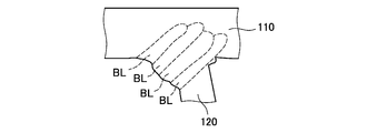
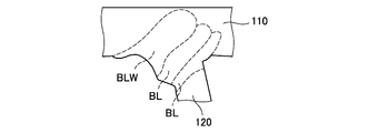
- FIG. 5 is a partially enlarged cross-sectional view showing the relationship between the laser beam irradiation point and the repair status in FIG. It is a partially enlarged sectional view which shows the relationship between the number of times of a laser beam irradiation pass of the repair laser welding method by one Embodiment of this disclosure, and a repair situation. It is a partially enlarged sectional view which shows the relationship between the number of times of a laser beam irradiation pass of the repair laser welding method by one Embodiment of this disclosure, and a repair situation. It is a partially enlarged sectional view which shows the relationship between the number of times of a laser beam irradiation pass of the repair laser welding method by one Embodiment of this disclosure, and a repair situation.
- FIG. 10A is a side explanatory view of the repair laser welding apparatus of FIG. 10A.
- FIG. 13B It is a conceptual diagram in the case of performing repair laser welding using the tab plate of FIG. 13B. It is a perspective explanatory view which shows the preferable form example to use in place of the tab plate of FIG. 13B.
- FIG. 3 is a perspective explanatory view showing another embodiment that is preferable to be used in place of the tab plate of FIG. 13B.
- FIG. 3 is a perspective explanatory view showing still another embodiment that is preferable to be used in place of the tab plate of FIG. 13B.
- FIG. 15A It is a side view of the state in which the backing plate is arranged when the repair laser welding is performed using the tab plate of FIG. 13B. It is an enlarged cross-sectional explanatory view which shows the repair procedure of the welded part at the part intersecting with the lateral rib of the steel plate slab to which the repair laser welding method of this disclosure is applied. It is an enlarged cross-sectional explanatory view which shows the repair procedure of the welded part at the part intersecting with the lateral rib of the steel plate slab to which the repair laser welding method of this disclosure is applied.
- FIGS. 1 and 2 show the steel deck slab of the steel deck box girder of the bridge to which the repair laser welding method according to the present disclosure is applied
- FIGS. 3 and 4 show the repair according to the embodiment of the present disclosure.
- the repair laser welding apparatus used for the laser welding method for steel is shown.
- the steel deck slab 103 constituting the steel deck slab box girder 100 together with the plurality of main girders includes a deck plate (one of the materials to be welded) 110 on which the pavement portion H of the bridge is placed and the deck plate.
- a plurality of U ribs (the other material to be welded) 120 arranged on the downward surface 112 on the opposite side of the pavement portion mounting surface 111 of 110 are provided.
- each of the tips of the pair of side edges 121 and 121 of the U rib 120 that obliquely abuts on the downward surface 112 of the deck plate 110 has a re-shaped groove 122 and 122, respectively. It is formed.
- the U-rib 120 is attached to the deck plate 110 by forming a weld bead B by fillet arc welding between the recesses 122 and 122 of the tray plate 110 and the downward surface 112 of the deck plate 110 over the entire length. As a result, a closed cross-sectional structure is formed together with the deck plate 110.
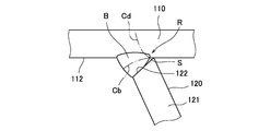
- the deck plate 110 is not welded to the root portion R at the joint portion between the side edges 121 and 121 of the U rib 120 obliquely joined on the downward surface 112 of the deck plate.
- a portion S remains, and a crack starting from the unwelded portion S (deck progress extending in the penetrating direction through the deck plate 110) occurs at the joint portion between the deck plate 110 and the U rib 120 due to aged deterioration and metal fatigue.
- a bead growth crack Cb) that propagates in the penetrating direction through the crack Cd and the weld bead B at the joint portion may occur.
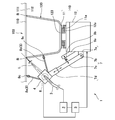
- the repair laser welding apparatus 1 for removing cracks Cd and Cb generated at the joint portion between the deck plate 110 and the U rib 120 is a laser as schematically shown in FIGS. 3 and 4.
- the drive mechanism 10 is provided.
- the head drive mechanism 10 includes a rail base 11 that is attracted and fixed to the bottom 123 between the side edges 121 and 121 of the U rib 120 by a magnet or the like, and a trolley 12 that mounts the laser head 4 via the arm 7 and travels. It is equipped.
- the carriage 12 is supported by hanging the wheels 12a, 12a on the rails 11a, 11a of the rail base 11, and is supported by the rail base 11.
- a motor (not shown) mounted on the carriage 12 It travels on the rails 11a and 11a, that is, travels along the weld bead B by the power from.
- the irradiation point of the laser beam L emitted from the laser head 4 moving along the welding bead B by the head drive mechanism 10 is made to follow the joint portion of the deck plate 110 and the U rib 120. It is provided with a copying mechanism 8.
- the copying mechanism 8 includes two copying legs 8a and 8b having rollers 8c at the tip arranged on the laser head 4, a sub-arm 9a provided on the carriage 12, and a tension spring 9b. Then, in the copying mechanism 8, the tension spring 9b is arranged between the sub-arm 9a and the arm 7, and the two copying legs 8a and 8b are placed on the downward surface 112 of the deck plate 110 and the side edge 121 of the U rib 120, respectively.
- the irradiation point of the laser beam L emitted from the laser head 4 is made to follow the joint portion of the deck plate 110 and the U rib 120.
- the copying mechanism for copying the irradiation point of the laser beam L to the joint portion of the deck plate 110 and the U rib 120 is not limited to the above configuration. For example, a non-contact type copying mechanism using a sensor may be used.
- the repair laser welding device 1 is provided with a weaving mechanism 6 built in the laser head 4, so that the laser beam L can be weaved in the direction crossing the welding bead B within the range of the arrow in FIG. ing.
- the repair laser welding device 1 is equipped with a shift mechanism.
- the arm 7 that supports the laser head 4 also serves as a shift mechanism.
- the arm 7 includes a support arm 7a provided on the carriage 12, an arm body 7c rotatably connected to the support arm 7a via a pin 7b, and an arm provided on the laser head 4 side. It is composed of a moving arm 7d that is movably fitted to the main body 7c in the axial direction (direction of the arrow in the figure).
- the irradiation point of the laser beam L is set to the deck plate 110 and the U rib 120 by moving the moving arm 7d with respect to the arm body 7c rotatably connected to the support arm 7a. It is possible to shift from the root portion R at the joint portion of the above to the weld bead B side.
- Reference numeral 5 in FIG. 3 is a control unit, and the control unit 5 controls the spot diameter of the laser beam L emitted from the laser head 4 and the movement of the laser head 4 by the head drive mechanism 10. There is.
- the deck plate 110 and the deck plate 110 and the U rib 120 are removed.
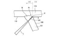
- a non-destructive inspection such as an ultrasonic flaw detection test was performed on the joint portion of the U rib 120, and as shown in FIG. 5, the joint portion of the U rib 120 and the downward surface 112 of the deck plate 110 included in the unwelded portion S of the root portion R.
- the position of the contact point P of the side edge 121 of the U rib 120 with the laser welding groove 122 is specified.
- the laser beam L touches the contact point P by adjusting the angle of the arm body 7c of the arm 7 (shift mechanism) that supports the laser head 4 and moving the moving arm 7d with respect to the arm body 7c.
- the irradiation point of the laser beam L is determined.
- the tension springs 9b of the copying mechanism 8 are set so that the two copying legs 8a and 8b are pressed against the downward surface 112 of the deck plate 110 and the side edges 121 of the U rib 120, respectively.
- the carriage 12 of the head drive mechanism 10 starts traveling by a command from the control unit 5, and the laser head 4 starts moving while appropriately irradiating the contact point P with the laser beam L having a spot diameter.
- the movement of the laser head 4 causes the laser beam L to pass (move) once along the welding bead B.
- the laser beam L is welded.
- the laser head 4 is moved while irradiating toward B.
- the downward surface 112 of the deck plate 110 of the steel deck 103 included in the unwelded portion S of the root portion R and the re-shaped groove 122 of the side edge 121 of the U rib 120 Since the contact point P is aimed at as the irradiation point of the laser beam L, the unwelded portion S in the root portion R can be melted. Then, as the unwelded portion S melts, the deck extension crack Cd generated starting from the unwelded portion S is also melted and removed.
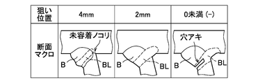
- FIG. 6 is a partially enlarged cross-sectional view showing the relationship between the laser beam irradiation point and the repair status, and shows the repair status when the laser beam L is passed once along the welding bead B.
- the irradiation point of the laser beam L it is desirable to set the irradiation point of the laser beam L so that at least the outer edge of the spot of the laser beam L touches the contact point P.
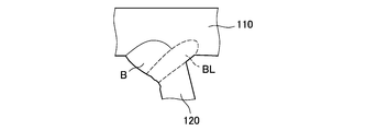
- the welding bead BL due to the irradiation of the laser beam L becomes as shown in the partially enlarged cross-sectional view of FIG. Since it does not reach the unwelded portion S, unwelded dust is generated. Therefore, in this embodiment in which the laser beam L is passed once along the welding bead B, it is desirable to set the irradiation point of the laser beam L to the welding bead B side by about 2 mm from the contact point P.
- the laser beam L is passed once along the weld bead B to form the weld bead BL by irradiation with the laser beam L.
- the deck extension crack Cd is large, the laser can be removed by the arm 7 that also serves as a shift mechanism, as shown in the partially enlarged cross-sectional view of FIG. 7B.
- FIG 8 and 9 show a repair laser welding apparatus used in the repair laser welding method according to another embodiment of the present disclosure.
- the repair laser welding apparatus 1A collects and repairs the laser light L supplied from the laser oscillator (not shown) via the optical fiber 3 as schematically shown in FIGS. 8 and 9. It includes a laser head 4 that irradiates a portion, and a head drive mechanism 10A that moves the laser head 4 along the welding bead B.
- the head drive mechanism 10A includes a rail 11A and a carriage 12A traveling on the rail 11A, and the laser head 4 is mounted on the carriage 12A via the arm 7A.
- the repair laser welding device 1A includes a rail arrangement mechanism 20, and the rail arrangement mechanism 20 includes an L-shaped member 22 in which magnets 21 and 21 are arranged at both ends, and a head drive mechanism. It includes a guide 23 arranged on a rail 11A of 10A.
- the rail 11A of the head drive mechanism 10A is fixed to the bottom 123 of the U rib 120 via one magnet 21 of the L-shaped member 22 of the rail arrangement mechanism 20.
- the other magnet 21 of the L-shaped member 22 is attracted to the downward surface 112 of the deck plate 110 (the surface of one material to be welded to which the other material to be welded is joined), and the guide 23 is attached to the U-rib 120. It is in contact with the side edge 121.
- the rail 11A of the head drive mechanism 10A is fixed with reference to both the downward surface 112 of the deck plate 110 and the side edge 121 of the U rib 120, whereby the rail 11A moves along with the carriage 12A along the weld bead B.
- the irradiation point of the laser beam L emitted from the laser head 4 is the joint portion between the deck plate 110 and the U rib 120 (the downward surface 112 and the U rib of the deck plate 110 included in the unwelded portion S in the root portion R of FIG. 5).
- the contact point P) of the side edge 121 of the 120 with the laser groove 122 is aimed at.
- the deck plate 110 and U A non-destructive inspection such as an ultrasonic flaw detection test is performed on the joint portion of the rib 120, and as shown in FIG. 5, the downward surface 112 and U of the deck plate 110 included in the unwelded portion S in the root portion R.
- the position of the contact point P of the side edge 121 of the rib 120 with the laser welding groove 122 is specified.
- the other magnet 21 of the L-shaped member 22 in the rail arrangement mechanism 20 is attracted to the downward surface 112 of the deck plate 110, and the guide 23 is brought into contact with the side edge 121 of the U rib 120, that is, the deck plate 110.
- the rail 11A of the head drive mechanism 10A is fixed to the bottom 123 of the U rib 120 via one magnet 21 of the L-shaped member 22 with reference to both the downward surface 112 and the side edge 121 of the U rib 120.
- the irradiation point of the laser beam L emitted from the laser head 4 moving along with the carriage 12A along the weld bead B is included in the unwelded portion S at the root portion R of the joint portion between the deck plate 110 and the U rib 120. It is set at the contact point P.
- the carriage 12A of the head drive mechanism 10A starts traveling, and the laser head 4 starts moving while appropriately irradiating the contact point P with the laser beam L having a spot diameter. Also in this embodiment, the movement of the laser head 4 causes the laser beam L to pass (move) once along the welding bead B.
- the downward surface 112 of the deck plate 110 of the steel deck 103 included in the unwelded portion S of the root portion R and the re-shaped groove 122 of the side edge 121 of the U rib 120 Since the contact point P with is aimed at as the irradiation point of the laser beam L, the unwelded portion S in the root portion R can be melted. Then, as the unwelded portion S melts, the deck extension crack Cd generated starting from the unwelded portion S is also melted and removed.
- 10A, 10B and 11 show a repair laser welding apparatus used in the repair laser welding method according to still another embodiment of the present disclosure.
- the repair laser welding apparatus 1B collects laser light L supplied from a laser oscillator (not shown) via an optical fiber 3 as schematically shown in FIGS. 10A, 10B and 11. It is provided with a laser head 4 that irradiates the repaired portion, and a head drive mechanism 10B that moves the laser head 4 along the welding bead B.
- the head drive mechanism 10B includes a rail 20B and a carriage 22B on which the laser head 4 is mounted.
- the rail 20B has an angle steel shape and includes a vertical plate member 22Y and a horizontal plate member 22X that are separably coupled to each other.
- the vertical plate member 22Y of the rail 20B has magnets 21 at the upper ends at both ends in the longitudinal direction (horizontal direction in FIG. 11), and the vertical plate member 22Y has a downward surface 112 of the deck plate 110 via the magnets 21. It is fixed to (the surface of one material to be welded to which the other material to be welded is joined). Further, grooves 22Ya along the vertical direction are formed at the lower end portions of the vertical plate member 22Y at both end portions in the longitudinal direction.
- the guide 23B is interposed between the vertical plate member 22Y and the side edge 121 of the U rib 120, so that the vertical plate member 22Y is positioned with respect to the U rib 120. I am trying to do it.
- the guide 23B is interposed at an appropriate position in the longitudinal direction of the vertical plate member 22Y, for example, at both ends, and is removed after the vertical plate member 22Y is fixed.
- the horizontal plate member 22X of the rail 20B has a groove insertion protrusion 22Xa inserted into the groove 22Ya of the vertical plate member 22Y at the base end portion (left end portion of FIG. 10A) and in the longitudinal direction (left-right direction of FIG. 11).
- a magnet 21 is provided at each tip (right end in FIG. 10A) at both ends.
- the horizontal plate material 22X is fixed to the bottom 123 of the U rib 120 via the magnet 21 in a state where the groove insertion protrusion 22Xa is inserted into the groove 22Ya of the vertical plate material 22Y. At this time, the horizontal plate material 22X is fixed to the groove 22Ya of the vertical plate material 22Y. By adjusting the vertical position of the groove insertion protrusion 22Xa, positioning is performed with reference to the downward surface 112 of the deck plate 110 (the surface of one material to be welded to which the other material to be welded is joined). It has become.
- a long member 22Yb is arranged on the horizontal plate member 22X so as to be parallel to the vertical plate member 22Y, and the vertical plate member 22Y and the long member 22Yb in the horizontal plate member 22X are formed as a traveling path.
- the carriage 22B of the head drive mechanism 10B travels along the traveling path on the positioned horizontal plate member 22X by being guided by the vertically positioned vertical plate member 22Y and the long member 22Yb. It is designed to do.
- the irradiation point of the laser beam L emitted from the laser head 4 moving along with the carriage 22B along the weld bead B is at the joint portion between the deck plate 110 and the U rib 120 (at the unwelded portion S in the root portion R of FIG. 5).
- the contact point P) between the downward surface 112 of the deck plate 110 and the laser groove 122 of the side edge 121 of the U rib 120 is aimed at.
- the deck plate 110 and U A non-destructive inspection such as an ultrasonic flaw detection test is performed on the joint portion of the rib 120, and as shown in FIG. 5, the downward surface 112 and U of the deck plate 110 included in the unwelded portion S in the root portion R.
- the position of the contact point P of the side edge 121 of the rib 120 with the laser welding groove 122 is specified.
- the downward surface 112 of the deck plate 110 (the other of the materials to be welded) 112 via the magnet 21. It is fixed to the surface to which the material to be welded is joined). That is, the vertical plate member 22Y of the rail 20B is fixed to the downward surface 112 of the deck plate 110 in a state where the U rib 120 is positioned.
- the horizontal plate material 22X is fixed to the bottom 123 of the U rib 120 via the magnet 21, and at this time, the vertical plate material 22X is fixed.
- the vertical position of the groove insertion protrusion 22Xa is adjusted with respect to the groove 22Ya of the 22Y, and positioning is performed with reference to the downward surface 112 (the surface of one material to be welded to which the other material to be welded is joined) of the deck plate 110. ..
- the traveling path of the carriage 22B that is guided by the vertical plate member 22Y and the long member 22Yb (along the welding bead B) is set on the horizontal plate member 22X, and is irradiated from the laser head 4 on the carriage 22B.
- the irradiation point of the laser beam L is set at the contact point P included in the unwelded portion S at the root portion R of the joint portion between the deck plate 110 and the U rib 120.
- the carriage 22B of the head drive mechanism 10B starts traveling and appropriately spots the contact point P.
- the laser head 4 starts moving while irradiating the laser beam L having a diameter. Also in this embodiment, the movement of the laser head 4 causes the laser beam L to pass (move) once along the welding bead B.
- the downward surface 112 of the deck plate 110 of the steel deck 103 included in the unwelded portion S of the root portion R and the re-shaped groove 122 of the side edge 121 of the U rib 120 Since the contact point P with is aimed at as the irradiation point of the laser beam L, the unwelded portion S in the root portion R can be melted. Then, as the unwelded portion S melts, the deck extension crack Cd generated starting from the unwelded portion S is also melted and removed.
- the repair laser welding apparatus 1B is composed of the vertical plate member 22Y and the horizontal plate member 22X that separately connect the rails 20B to each other, the deck plate 110 is used when the rails 20B are installed.
- the vertical plate member 22Y and the horizontal plate member 22X are positioned and installed one by one with respect to the downward surface 112 and the U rib 120.
- each work can be performed without feeling the weight so much, and as a result, the workability is improved by the amount that the positioning and installation of the rail 20B are facilitated.
- the traveling path of the carriage 22B is set on the horizontal plate member 22X of the rail 20B, the aiming work of the laser beam L emitted from the laser head 4 can be performed. It will be easy to do.
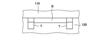
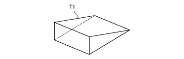
- the rectangular body shown in FIG. 12A is used.
- tab plates T having a shape are arranged at two locations, the start end and the end of the repair welded portion in the weld bead B, to perform laser welding, and after the laser welding for repair is completed, the tab plate T, I try to remove T.
- irradiation of the laser beam L is started in order to receive heat from the side surface (so-called edge surface) of the tab plate T2 on one side (left side in the drawing) held in a surface contact state with an inclination on the surface Wp of the steel material W.
- the laser beam L is set so as to be substantially perpendicular to the surface Wp of the steel material W and the distance is constant, the energy density is low in the vicinity of each edge surface of the tab plates T2 and T2 and the laser beam L does not melt.
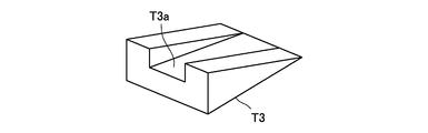
- a tab plate T3 having a groove T3a along the welding direction is adopted as shown in FIG. 15A, or a tab plate T3 having a groove T3a along the welding direction is adopted or cut into the edge surface as shown in FIG. 15B.
- a tab plate T4 having a notch T4a or a tab plate T5 having a step T5a on the edge surface is adopted as shown in FIG. 15C so that a temperature difference does not occur in the thickness direction of the steel material W. Is desirable.
- the base metal melts at each time of the start of laser light irradiation and the end of laser light irradiation.
- a backing plate U made of a steel material, a ceramic or the like is applied to the edge surface of the tab plate T3 (T4, T5), or as shown in FIG. 16B, the backing plate U Is desirable to be fitted into the notch Ta formed in the tab plate T3 (T4, T5), and when the tab plate T2 having a trapezoidal side view is used, as shown in FIG. 16C, the tab plate T2 It is desirable to put a backing plate U underneath.
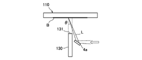
- FIG. 17A and 17B show scalloped portions of the lateral ribs 130 arranged across the U ribs when the repair laser welding is performed on the joint portion between the deck plate 110 and the U ribs by the repair laser welding method according to this embodiment. The case where the laser beam L is irradiated to the portion located at 131 is shown.
- the laser head moves from the left side in the drawing to the right side in the drawing (in FIG. 17A). (Not shown) is temporarily stopped in front of the lateral rib 130, and in this state, the portion of the lateral rib 130 located at the scalloped portion 131 is irradiated with the laser beam L via the mirror 4a.
- the laser head is positioned on the right side of the horizontal rib 130 in the drawing, and the portion of the horizontal rib 130 located on the scalloped portion 131 is irradiated with the laser beam L through the mirror 4a. That is, the portion located at the scalloped portion 131 is welded so as to wrap.
- the laser beam L It is desirable that the irradiation angle ⁇ with respect to the lateral rib 130 is at least 1/2 or more of the tangent angle ⁇ of tan ⁇ represented by t / R.
- the repair laser welding method according to the present disclosure is used to join a deck plate constituting a steel deck plate of a bridge and a U-rib joined by fillet welding on the surface of the deck plate.
- the case where it is used for repairing a crack formed in a portion has been described as an example, but the present invention is not limited to this.
- the cracks are removed only by irradiating the laser beam L, but the present invention is not limited to this, and other configurations include, for example, a laser while supplying a molten material.
- the light L may be irradiated, and when the laser light L is irradiated while supplying the molten material in this way, the cracks can be reliably removed.
- the cracks are removed only by irradiating the laser beam L, but other welding, for example, arc welding may be used in combination.
- the configuration of the repair laser welding method and the repair laser welding apparatus according to the present disclosure is not limited to each of the above-described embodiments, and can be variously modified without departing from the purpose of the disclosure.
- the first aspect of the present disclosure is not at the root portion between one material to be welded and the other material to be welded obliquely joined by fillet welding to the surface of the one material to be welded.
- a repair laser welding method in which cracks generated from a welded portion are melted and eliminated by irradiation with laser light, and the one welded material and the other welded material contained in the unwelded portion in the root portion are welded.
- the laser beam is irradiated along the weld bead while aiming at the contact point with the material as the irradiation point of the laser beam from the welding bead side of the root portion.
- the contact points between one material to be welded and the other material to be welded included in the unwelded portion in the root portion are located by non-destructive inspection.
- the irradiation point of the laser beam is shifted from the contact point to the welding bead side, and the laser beam is passed along the welding bead a plurality of times. At this time, the amount of one shift of the irradiation point of the laser beam is determined based on the spot diameter of the laser beam.
- the third aspect of the present disclosure is configured to irradiate the laser beam along the weld bead while weaving the laser beam in a direction crossing the weld bead.
- a fourth aspect of the present disclosure is to aim the contact point between the one welded material and the other welded material contained in the unwelded portion in the root portion as an irradiation point of the laser beam.
- the irradiation point is set so that at least the outer edge of the spot of the laser beam touches the contact point.
- the fifth aspect of the present disclosure is such that the laser beam is irradiated while supplying the molten material.
- the sixth aspect of the present disclosure is a root portion between one material to be welded and the other material to be welded obliquely joined to the surface of the one material to be welded by fillet welding.
- a repair laser welding device that melts and eliminates cracks generated starting from an unwelded portion in the above by irradiation with a laser beam, the laser oscillator, a laser head that irradiates the laser beam supplied from the laser oscillator, and the like.
- the root portion includes a head drive mechanism that moves the laser head along the weld bead of the root portion and an irradiation point of the laser beam emitted from the laser head that moves along the weld bead by the head drive mechanism.
- the configuration is provided with a copying mechanism that imitates the contact point between the one welded material and the other welded material contained in the unwelded portion of the above.
- a seventh aspect of the present disclosure is a root portion between one material to be welded and the other material to be welded obliquely joined by fillet welding to the surface of the one material to be welded.
- a repair laser welding device that melts and eliminates cracks generated from an unwelded portion as a starting point by irradiation with a laser beam, and includes a laser oscillator, a laser head that irradiates the laser beam supplied from the laser oscillator, and the like.
- the head drive mechanism for moving the laser head along the weld bead of the root portion is provided, and the head drive mechanism includes a rail and a carriage on which the laser head is mounted and travels on the rail.
- the irradiation point of the laser beam emitted from the laser head that moves along with the trolley along the weld bead is the one welded material and the other welded material included in the unwelded portion in the root portion.
- the structure is such that both the surface to which the other material to be welded is joined and the other material to be welded are fixed as a reference.
- the rail of the head drive mechanism has a chevron steel shape including a vertical plate material and a horizontal plate material that are separably coupled to each other, and the vertical plate material of the rail is the said.
- the horizontal plate material of the rail is positioned and fixed with reference to the other material to be welded, and the horizontal plate material of the rail is the other of the vertical plate material fixed with reference to the other material to be welded.
- the horizontal plate material of the rail is positioned and fixed with reference to the surface to which the material to be welded is joined, and the carriage of the head drive mechanism placed on the horizontal plate material is guided by the vertical plate material to travel.
- the structure is formed as a road.
- the ninth aspect of the present disclosure is configured to include a weaving mechanism for weaving the laser beam in a direction crossing the weld bead.
- the irradiation point of the laser beam is the one welded material and the other coated material in which at least the outer edge of the spot of the laser beam is included in the unwelded portion in the root portion.
- the configuration is set so that it touches the contact point with the welding material.
- a YAG laser or a semiconductor laser is generally used as the laser, but the laser is not limited to these.
Landscapes
- Physics & Mathematics (AREA)
- Optics & Photonics (AREA)
- Engineering & Computer Science (AREA)
- Mechanical Engineering (AREA)
- Plasma & Fusion (AREA)
- Architecture (AREA)
- Civil Engineering (AREA)
- Structural Engineering (AREA)
- Robotics (AREA)
- Laser Beam Processing (AREA)
- Bridges Or Land Bridges (AREA)
Abstract
Description
この溶接方法では、ビードに生じるき裂の進展方向となるようにレーザ光の照射方向を設定することで、き裂を消去するようにしている。
なお、ルート部における未溶着部分に含まれる一方の被溶接材と他方の被溶接材との接触点は、非破壊検査によって位置を特定する。
図1及び図2は、本開示に係る補修用レーザ溶接方法が適用される橋梁の鋼床版箱桁の鋼床版を示し、図3及び図4は、本開示の一実施形態に係る補修用レーザ溶接方法に用いる補修用レーザ溶接装置を示している。
なお、レーザ光Lの照射ポイントをデッキプレート110及びUリブ120の接合部分に倣わせる倣い機構は、上記の構成のものに限定されない。例えば、センサによる非接触タイプの倣い機構を用いてもよい。
この実施形態において、このレーザヘッド4の移動により、レーザ光Lは、溶接ビードBに沿って1回パス(移動)するようになっている。
この際、レーザ光Lの焦点が上記接触点Pに合致するように設定したとしても、実際には、レーザ光Lのスポットの外縁がUリブ120の内側(0未満(-)の領域)に入り込むことになる。
したがって、レーザ光Lのスポットの少なくとも外縁が接触点Pに触れるべくレーザ光Lの照射ポイントを設定することが望ましく、このようにレーザ光Lの照射ポイントを設定することで、レーザ光Lの照射による溶融金属のUリブ120内側への流動を確実に防ぐことができる。
したがって、レーザ光Lを溶接ビードBに沿って1回パスさせるこの実施形態では、レーザ光Lの照射ポイントを上記接触点Pから2mm程度溶接ビードB側に設定することが望ましいことが判る。
この実施形態においても、このレーザヘッド4の移動により、レーザ光Lは、溶接ビードBに沿って1回パス(移動)するようになっている。
また、この縦板材22Yの長手方向の両端部における各下端部には上下方向に沿う溝22Yaが形成されている。
このガイド23Bは、縦板材22Yの長手方向の適宜位置、例えば両端部に介在させ、縦板材22Yの固定後には除去されるものとなっている。
この実施形態においても、このレーザヘッド4の移動により、レーザ光Lは、溶接ビードBに沿って1回パス(移動)するようになっている。
なお、ルート部における未溶着部分に含まれる一方の被溶接材と他方の被溶接材との接触点は、非破壊検査によって位置を特定する。
この際、レーザ光の照射ポイントの1回のシフト量は、レーザ光のスポット径に基づいて決定する。
2 レーザ発振器
4 レーザヘッド
6 ウィービング機構
7 アーム(シフト機構)
8 倣い機構
10,10A,10B ヘッド駆動機構
11A,20B レール
12A,22B 台車
22X 横板材(レール)
22Y 縦板材(レール)
103 鋼床版
110 デッキプレート(一方の被溶接材)
112 下向き面(一方の被溶接材における他方の被溶接材が接合される面)
120 Uリブ(他方の被溶接材)
121 Uリブの側縁
122 レ型開先
B 溶接ビード
Cb ビード進展き裂
Cd デッキ進展き裂
P 接触点
R ルート部
S 未溶着部分
Claims (10)
- 一方の被溶接材と、該一方の被溶接材の面上に対して隅肉溶接により斜めに接合された他方の被溶接材との間のルート部における未溶着部分を起点として生じたき裂をレーザ光の照射により溶融させて消去する補修用レーザ溶接方法であって、
前記ルート部における未溶着部分に含まれる前記一方の被溶接材と前記他方の被溶接材との接触点を前記レーザ光の照射ポイントとして前記ルート部の溶接ビード側から狙いつつ、該溶接ビードに沿って前記レーザ光を照射する補修用レーザ溶接方法。 - 前記レーザ光の照射ポイントを前記接触点から前記溶接ビード側にシフトさせて前記レーザ光を前記溶接ビードに沿って複数回パスさせる請求項1に記載の補修用レーザ溶接方法。
- 前記溶接ビードを横切る方向に前記レーザ光をウィービングさせつつ該溶接ビードに沿って前記レーザ光を照射する請求項1又は2に記載の補修用レーザ溶接方法。
- 前記ルート部における未溶着部分に含まれる前記一方の被溶接材と前記他方の被溶接材との接触点を前記レーザ光の照射ポイントとして狙うに際して、前記レーザ光のスポットの少なくとも外縁が前記接触点に触れるべく照射ポイントを設定する請求項1~3のいずれか一つの項に記載の補修用レーザ溶接方法。
- 溶材を供給しつつ前記レーザ光を照射する請求項1~4のいずれか一つの項に記載の補修用レーザ溶接方法。
- 一方の被溶接材と、該一方の被溶接材の面上に対して隅肉溶接により斜めに接合された他方の被溶接材との間のルート部における未溶着部分を起点として生じたき裂をレーザ光の照射により溶融させて消去する補修用レーザ溶接装置であって、
レーザ発振器と、
前記レーザ発振器から供給されるレーザ光を照射するレーザヘッドと、
前記レーザヘッドを前記ルート部の溶接ビードに沿って移動させるヘッド駆動機構と、
前記ヘッド駆動機構により前記溶接ビードに沿って移動する前記レーザヘッドから照射される前記レーザ光の照射ポイントを前記ルート部における未溶着部分に含まれる前記一方の被溶接材と前記他方の被溶接材との接触点に倣わせる倣い機構を備えている補修用レーザ溶接装置。 - 一方の被溶接材と、該一方の被溶接材の面上に対して隅肉溶接により斜めに接合された他方の被溶接材との間のルート部における未溶着部分を起点として生じたき裂をレーザ光の照射により溶融させて消去する補修用レーザ溶接装置であって、
レーザ発振器と、
前記レーザ発振器から供給されるレーザ光を照射するレーザヘッドと、
前記レーザヘッドを前記ルート部の溶接ビードに沿って移動させるヘッド駆動機構を備え、
前記ヘッド駆動機構は、レール及び前記レーザヘッドを搭載して前記レール上を走行する台車を具備し、前記レールは、前記溶接ビードに沿って前記台車とともに移動する前記レーザヘッドから照射される前記レーザ光の照射ポイントを前記ルート部における未溶着部分に含まれる前記一方の被溶接材と前記他方の被溶接材との接触点とするべく、前記一方の被溶接材における前記他方の被溶接材が接合される面及び該他方の被溶接材の双方を基準にして固定されている補修用レーザ溶接装置。 - 前記ヘッド駆動機構の前記レールは、互いに分離可能に結合する縦板材及び横板材を具備した山形鋼形状を成し、
前記レールの前記縦板材は、前記他方の被溶接材を基準にして位置決め固定され、
前記レールの前記横板材は、前記他方の被溶接材を基準にして固定された前記縦板材に対して前記一方の被溶接材における前記他方の被溶接材が接合される面を基準にして位置決め固定され、
前記レールの前記横板材は、該横板材上に載置した前記ヘッド駆動機構の前記台車が前記縦板材に案内されて走行する走行路として形成されている請求項7に記載の補修用レーザ溶接装置。 - 前記溶接ビードを横切る方向に前記レーザ光をウィービングさせるウィービング機構を備えている請求項6~8のいずれか一つの項に記載の補修用レーザ溶接装置。
- 前記レーザ光の照射ポイントは、該レーザ光のスポットの少なくとも外縁が前記ルート部における未溶着部分に含まれる前記一方の被溶接材と前記他方の被溶接材との接触点に触れるべく設定されている請求項6~9のいずれか一つの項に記載の補修用レーザ溶接装置。
Priority Applications (4)
| Application Number | Priority Date | Filing Date | Title |
|---|---|---|---|
| EP20843297.1A EP4005724B1 (en) | 2019-07-24 | 2020-07-22 | Repairing laser welding method and use of a laser welding device for repairing |
| JP2021534055A JP7202464B2 (ja) | 2019-07-24 | 2020-07-22 | 補修用レーザ溶接方法及び補修用レーザ溶接装置 |
| US17/563,181 US12459057B2 (en) | 2019-07-24 | 2021-12-28 | Repairing laser welding method and repairing laser welding device |
| US19/353,324 US20260034610A1 (en) | 2019-07-24 | 2025-10-08 | Repairing laser welding method and repairing laser welding device |
Applications Claiming Priority (2)
| Application Number | Priority Date | Filing Date | Title |
|---|---|---|---|
| JP2019136084 | 2019-07-24 | ||
| JP2019-136084 | 2019-07-24 |
Related Child Applications (1)
| Application Number | Title | Priority Date | Filing Date |
|---|---|---|---|
| US17/563,181 Continuation US12459057B2 (en) | 2019-07-24 | 2021-12-28 | Repairing laser welding method and repairing laser welding device |
Publications (1)
| Publication Number | Publication Date |
|---|---|
| WO2021015216A1 true WO2021015216A1 (ja) | 2021-01-28 |
Family
ID=74194214
Family Applications (1)
| Application Number | Title | Priority Date | Filing Date |
|---|---|---|---|
| PCT/JP2020/028349 Ceased WO2021015216A1 (ja) | 2019-07-24 | 2020-07-22 | 補修用レーザ溶接方法及び補修用レーザ溶接装置 |
Country Status (4)
| Country | Link |
|---|---|
| US (2) | US12459057B2 (ja) |
| EP (1) | EP4005724B1 (ja) |
| JP (1) | JP7202464B2 (ja) |
| WO (1) | WO2021015216A1 (ja) |
Cited By (3)
| Publication number | Priority date | Publication date | Assignee | Title |
|---|---|---|---|---|
| CN113828923A (zh) * | 2021-10-18 | 2021-12-24 | 光惠(上海)激光科技有限公司 | 一种焊接用的手持激光器 |
| CN115625422A (zh) * | 2022-09-30 | 2023-01-20 | 上海杭和智能科技有限公司 | 箱体导轨激光穿透焊接的夹具结构及方法 |
| JP7288556B1 (ja) | 2022-10-20 | 2023-06-07 | 武漢▲り▼▲しん▼自動化科技有限公司 | 現役の鋼構造橋梁のuリブの内面隅肉の溶接方法及び溶接システム |
Citations (4)
| Publication number | Priority date | Publication date | Assignee | Title |
|---|---|---|---|---|
| JP2005111517A (ja) * | 2003-10-07 | 2005-04-28 | Babcock Hitachi Kk | 高ニッケル合金の応力腐食割れ改善方法及び補修方法 |
| JP2010133835A (ja) * | 2008-12-04 | 2010-06-17 | Hanshin Expressway Co Ltd | 橋梁床版の亀裂検出方法 |
| JP2013086163A (ja) * | 2011-10-21 | 2013-05-13 | Ihi Corp | 亀裂の補修方法 |
| JP6092163B2 (ja) | 2014-07-30 | 2017-03-08 | 三菱重工業株式会社 | 溶接装置及び溶接方法 |
Family Cites Families (19)
| Publication number | Priority date | Publication date | Assignee | Title |
|---|---|---|---|---|
| JPH08187587A (ja) * | 1994-12-28 | 1996-07-23 | Ishikawajima Harima Heavy Ind Co Ltd | T継手用レーザ隅肉溶接方法及び装置 |
| JP3596329B2 (ja) * | 1999-02-16 | 2004-12-02 | 日産自動車株式会社 | レーザ溶接装置およびレーザ溶接方法 |
| JP4355621B2 (ja) * | 2004-06-25 | 2009-11-04 | 株式会社東京鐵骨橋梁 | 鋼床版の補修方法および補強方法 |
| WO2008015727A1 (en) * | 2006-07-31 | 2008-02-07 | Ihi Corporation | Rigidity reinforcement plate and method of producing rigidity reinforcement plate |
| JPWO2010123035A1 (ja) * | 2009-04-22 | 2012-10-25 | 株式会社Ihi検査計測 | ハイブリッド溶接方法及びハイブリッド溶接装置 |
| KR101111257B1 (ko) * | 2009-09-24 | 2012-02-22 | 대우조선해양 주식회사 | 자동 용접 로봇 |
| DE102009057997A1 (de) * | 2009-12-11 | 2011-06-22 | Daimler AG, 70327 | Verfahren zum Verschweißen von zwei Metallbauteilen |
| JP6196561B2 (ja) | 2013-06-21 | 2017-09-13 | 株式会社Ihi | 補修用レーザ溶接装置 |
| JP6032236B2 (ja) * | 2014-04-08 | 2016-11-24 | トヨタ自動車株式会社 | レーザ溶接方法および溶接構造 |
| JP6536365B2 (ja) | 2015-03-31 | 2019-07-03 | 日本製鉄株式会社 | 鋼床版の疲労亀裂発生防止方法および内面押圧装置 |
| JP6385911B2 (ja) * | 2015-11-12 | 2018-09-05 | 株式会社東芝 | 検出システム、情報処理装置、および検出方法 |
| JP6705336B2 (ja) * | 2016-08-12 | 2020-06-03 | 日本製鉄株式会社 | 鋼床版の疲労亀裂発生抑制方法、鋼床版の製造方法、および内面押圧装置 |
| JP6689238B2 (ja) * | 2017-08-24 | 2020-04-28 | 株式会社Ihi検査計測 | 仮付け溶接方法及び仮付け溶接装置 |
| JP6722625B2 (ja) * | 2017-08-24 | 2020-07-15 | 株式会社Ihi検査計測 | ハイブリッド溶接方法及びハイブリッド溶接装置 |
| WO2019208270A1 (ja) * | 2018-04-27 | 2019-10-31 | 株式会社Ihi | 補修用レーザ溶接方法及び補修用レーザ溶接装置 |
| JP7017497B2 (ja) * | 2018-10-19 | 2022-02-08 | フタバ産業株式会社 | 溶接方法 |
| JP6898287B2 (ja) * | 2018-10-19 | 2021-07-07 | フタバ産業株式会社 | 溶接方法 |
| DE102018220445A1 (de) * | 2018-11-28 | 2020-05-28 | Trumpf Laser- Und Systemtechnik Gmbh | Verfahren zum Stoßschweißen zweier Werkstücke mittels eines UKP-Laserstrahls sowie zugehöriges optisches Element |
| JP7082329B2 (ja) * | 2019-02-01 | 2022-06-08 | 株式会社Ihi | き裂補修方法 |
-
2020
- 2020-07-22 EP EP20843297.1A patent/EP4005724B1/en active Active
- 2020-07-22 JP JP2021534055A patent/JP7202464B2/ja active Active
- 2020-07-22 WO PCT/JP2020/028349 patent/WO2021015216A1/ja not_active Ceased
-
2021
- 2021-12-28 US US17/563,181 patent/US12459057B2/en active Active
-
2025
- 2025-10-08 US US19/353,324 patent/US20260034610A1/en active Pending
Patent Citations (4)
| Publication number | Priority date | Publication date | Assignee | Title |
|---|---|---|---|---|
| JP2005111517A (ja) * | 2003-10-07 | 2005-04-28 | Babcock Hitachi Kk | 高ニッケル合金の応力腐食割れ改善方法及び補修方法 |
| JP2010133835A (ja) * | 2008-12-04 | 2010-06-17 | Hanshin Expressway Co Ltd | 橋梁床版の亀裂検出方法 |
| JP2013086163A (ja) * | 2011-10-21 | 2013-05-13 | Ihi Corp | 亀裂の補修方法 |
| JP6092163B2 (ja) | 2014-07-30 | 2017-03-08 | 三菱重工業株式会社 | 溶接装置及び溶接方法 |
Non-Patent Citations (1)
| Title |
|---|
| See also references of EP4005724A4 |
Cited By (5)
| Publication number | Priority date | Publication date | Assignee | Title |
|---|---|---|---|---|
| CN113828923A (zh) * | 2021-10-18 | 2021-12-24 | 光惠(上海)激光科技有限公司 | 一种焊接用的手持激光器 |
| CN113828923B (zh) * | 2021-10-18 | 2022-07-15 | 光惠(上海)激光科技有限公司 | 一种焊接用的手持激光器 |
| CN115625422A (zh) * | 2022-09-30 | 2023-01-20 | 上海杭和智能科技有限公司 | 箱体导轨激光穿透焊接的夹具结构及方法 |
| JP7288556B1 (ja) | 2022-10-20 | 2023-06-07 | 武漢▲り▼▲しん▼自動化科技有限公司 | 現役の鋼構造橋梁のuリブの内面隅肉の溶接方法及び溶接システム |
| JP2024061575A (ja) * | 2022-10-20 | 2024-05-07 | 武漢▲り▼▲しん▼自動化科技有限公司 | 現役の鋼構造橋梁のuリブの内面隅肉の溶接方法及び溶接システム |
Also Published As
| Publication number | Publication date |
|---|---|
| JP7202464B2 (ja) | 2023-01-11 |
| US20220118552A1 (en) | 2022-04-21 |
| EP4005724B1 (en) | 2025-04-09 |
| JPWO2021015216A1 (ja) | 2021-01-28 |
| EP4005724A1 (en) | 2022-06-01 |
| EP4005724A4 (en) | 2023-09-06 |
| US12459057B2 (en) | 2025-11-04 |
| US20260034610A1 (en) | 2026-02-05 |
Similar Documents
| Publication | Publication Date | Title |
|---|---|---|
| US20260034610A1 (en) | Repairing laser welding method and repairing laser welding device | |
| JP6095456B2 (ja) | レーザ溶接方法およびレーザ・アークハイブリッド溶接方法 | |
| JPWO2010123035A1 (ja) | ハイブリッド溶接方法及びハイブリッド溶接装置 | |
| CN105149786B (zh) | 一种基于预制焊材的窄间隙激光扫描多层自熔焊接方法 | |
| RU2136465C1 (ru) | Способ дуговой сварки в защитных газах стальных железнодорожных рельс (варианты) | |
| JP5860264B2 (ja) | 亀裂の補修方法 | |
| JP6391412B2 (ja) | レーザ溶接方法及びレーザ溶接装置 | |
| CN102728960A (zh) | 混合焊接设备和焊接的系统与方法 | |
| JP6689238B2 (ja) | 仮付け溶接方法及び仮付け溶接装置 | |
| JP2021167026A (ja) | 溶接部欠陥の補修方法 | |
| JP6092163B2 (ja) | 溶接装置及び溶接方法 | |
| JP5812527B2 (ja) | ホットワイヤレーザ溶接方法と装置 | |
| JP7032707B2 (ja) | 補修用レーザ溶接方法及び補修用レーザ溶接装置 | |
| EP2047935B1 (en) | Method of producing a stiffened plate | |
| CN110997219B (zh) | 复合焊接方法及复合焊接装置 | |
| JP2013091912A (ja) | 鋼床版の溶接部の補修方法及び補修装置 | |
| JPWO2020158878A1 (ja) | き裂補修方法 | |
| JP5851213B2 (ja) | アーク及びレーザーを用いた溶接方法と溶接装置 | |
| JP5352226B2 (ja) | ダブルスキンパネルのレーザ溶接継手 | |
| JP2006346709A (ja) | 薄板縁継手のレーザ溶接方法 | |
| JP2011200890A (ja) | レーザー溶接方法 | |
| JP2023163707A (ja) | レーザ溶接装置、レーザ溶接プログラム、及びレーザ溶接方法 | |
| KR20230147890A (ko) | 와이드 갭 플라즈마 아크 용접 방법 | |
| JPS6365435B2 (ja) | ||
| CN121649528A (zh) | 动车组用铝合金端墙自动焊焊接方法 |
Legal Events
| Date | Code | Title | Description |
|---|---|---|---|
| 121 | Ep: the epo has been informed by wipo that ep was designated in this application |
Ref document number: 20843297 Country of ref document: EP Kind code of ref document: A1 |
|
| ENP | Entry into the national phase |
Ref document number: 2021534055 Country of ref document: JP Kind code of ref document: A |
|
| NENP | Non-entry into the national phase |
Ref country code: DE |
|
| WWE | Wipo information: entry into national phase |
Ref document number: 2020843297 Country of ref document: EP |
|
| ENP | Entry into the national phase |
Ref document number: 2020843297 Country of ref document: EP Effective date: 20220224 |
|
| WWG | Wipo information: grant in national office |
Ref document number: 2020843297 Country of ref document: EP |