WO2021015231A1 - 学習装置、方法およびプログラム、関心領域抽出装置、方法およびプログラム、並びに学習済み抽出モデル - Google Patents
学習装置、方法およびプログラム、関心領域抽出装置、方法およびプログラム、並びに学習済み抽出モデル Download PDFInfo
- Publication number
- WO2021015231A1 WO2021015231A1 PCT/JP2020/028415 JP2020028415W WO2021015231A1 WO 2021015231 A1 WO2021015231 A1 WO 2021015231A1 JP 2020028415 W JP2020028415 W JP 2020028415W WO 2021015231 A1 WO2021015231 A1 WO 2021015231A1
- Authority
- WO
- WIPO (PCT)
- Prior art keywords
- image
- decoder
- discriminator
- encoder
- learning
- Prior art date
- Legal status (The legal status is an assumption and is not a legal conclusion. Google has not performed a legal analysis and makes no representation as to the accuracy of the status listed.)
- Ceased
Links
Images



Classifications
-
- A—HUMAN NECESSITIES
- A61—MEDICAL OR VETERINARY SCIENCE; HYGIENE
- A61B—DIAGNOSIS; SURGERY; IDENTIFICATION
- A61B6/00—Apparatus or devices for radiation diagnosis; Apparatus or devices for radiation diagnosis combined with radiation therapy equipment
- A61B6/52—Devices using data or image processing specially adapted for radiation diagnosis
- A61B6/5211—Devices using data or image processing specially adapted for radiation diagnosis involving processing of medical diagnostic data
- A61B6/5229—Devices using data or image processing specially adapted for radiation diagnosis involving processing of medical diagnostic data combining image data of a patient, e.g. combining a functional image with an anatomical image
- A61B6/5247—Devices using data or image processing specially adapted for radiation diagnosis involving processing of medical diagnostic data combining image data of a patient, e.g. combining a functional image with an anatomical image combining images from an ionising-radiation diagnostic technique and a non-ionising radiation diagnostic technique, e.g. X-ray and ultrasound
-
- G—PHYSICS
- G06—COMPUTING OR CALCULATING; COUNTING
- G06V—IMAGE OR VIDEO RECOGNITION OR UNDERSTANDING
- G06V10/00—Arrangements for image or video recognition or understanding
- G06V10/20—Image preprocessing
- G06V10/25—Determination of region of interest [ROI] or a volume of interest [VOI]
-
- G—PHYSICS
- G06—COMPUTING OR CALCULATING; COUNTING
- G06V—IMAGE OR VIDEO RECOGNITION OR UNDERSTANDING
- G06V10/00—Arrangements for image or video recognition or understanding
- G06V10/40—Extraction of image or video features
-
- G—PHYSICS
- G06—COMPUTING OR CALCULATING; COUNTING
- G06V—IMAGE OR VIDEO RECOGNITION OR UNDERSTANDING
- G06V10/00—Arrangements for image or video recognition or understanding
- G06V10/70—Arrangements for image or video recognition or understanding using pattern recognition or machine learning
- G06V10/77—Processing image or video features in feature spaces; using data integration or data reduction, e.g. principal component analysis [PCA] or independent component analysis [ICA] or self-organising maps [SOM]; Blind source separation
- G06V10/7715—Feature extraction, e.g. by transforming the feature space, e.g. multi-dimensional scaling [MDS]; Mappings, e.g. subspace methods
-
- A—HUMAN NECESSITIES
- A61—MEDICAL OR VETERINARY SCIENCE; HYGIENE
- A61B—DIAGNOSIS; SURGERY; IDENTIFICATION
- A61B6/00—Apparatus or devices for radiation diagnosis; Apparatus or devices for radiation diagnosis combined with radiation therapy equipment
- A61B6/02—Arrangements for diagnosis sequentially in different planes; Stereoscopic radiation diagnosis
- A61B6/03—Computed tomography [CT]
-
- G—PHYSICS
- G06—COMPUTING OR CALCULATING; COUNTING
- G06V—IMAGE OR VIDEO RECOGNITION OR UNDERSTANDING
- G06V2201/00—Indexing scheme relating to image or video recognition or understanding
- G06V2201/03—Recognition of patterns in medical or anatomical images
Definitions
- the present disclosure relates to a learning device, a method and a program for learning an extraction model for extracting an area of interest from an image, an area of interest extraction device, a method and a program for extracting an area of interest from an image, and a trained extraction model.
- GAN Generic Adversarial Networks
- Non-Patent Document 2 below also proposes a technique for performing domain adaptation between two different domains, source and target.
- the method described in Non-Patent Document 2 is based on the idea of learning so that the feature space of the source image and the target image are close to each other, and the method described in Non-Patent Document 2 has a sufficient teacher label.
- the source domain can be used to learn the target domain with no or few teacher labels with high accuracy.
- Non-Patent Document 3 proposes a network that realizes multimodal domain conversion by using a single generator and a discriminator.
- the method described in Non-Patent Document 3 simultaneously gives various facial expressions (for example, blonde hair, black hair, smiling face, angry face, etc.) of the image to be converted (for example, a person's face image) as domain labels to the input of the generator, and discs.
- facial expressions for example, blonde hair, black hair, smiling face, angry face, etc.
- the facial expression is determined to learn the generator and the discriminator.
- CT Computer Tomography
- MRI Magnetic Resonance Imaging
- a technique has been proposed in which a machine learning model such as a neural network is learned by using a learning image and a correct mask of the region of interest to extract the region of interest from an input image.
- Non-Patent Document 1 Ian J. Goodfellow, Jean Pouget-Abadie, Mehdi Mirza, Bing Xu, David Warde-Farley, Sherjil Ozair, Aaron Courville, Yoshua Bengio "Generative Adversarial Nets", arXiv: 1406.2661
- Non-Patent Document 2 Judy Hoffman, Eric Tzeng, Taesung Park, Jun-Yan Zhu, Phillip Isola, Kate Saenko, Alexei A.
- Non-Patent Document 3 Yunjey Choi, Minje Choi, Munyoung Kim, Jung-Woo Ha, Sunghun Kim, Jaegul Choo "StarGAN: Unified Generative Adversarial Networks for Multi-Domain Image-to-Image Translation", arXiv: 1711.09020
- medical images have different image representation formats when the modality for generating images is different, such as CT devices and MRI devices.
- the MRI image has various imaging conditions such as a T1-weighted image, a T2-weighted image, a fat-suppressed image, and a diffusion-weighted image, and the expression format differs depending on the imaging conditions.
- T1-weighted images predominantly adipose tissue appears white, water, humoral components and cysts appear black, and tumors appear slightly black.
- Non-Patent Document 2 only supports one-to-one domain conversion of one source and one target. Therefore, in order to correspond to medical images having various expression formats, it is necessary to prepare a model for each domain, that is, a combination of expression formats. Further, in the method described in Non-Patent Document 3, the method described in Non-Patent Document 3 can be applied only to the process of converting an image. Further, the method described in Non-Patent Document 3 requires a domain label for the input of the generator at the time of discrimination.
- the present disclosure has been made in view of the above circumstances, and an object of the present disclosure is to enable extraction of an area of interest included in a target image regardless of the expression format of the target image.
- the first learning device is a learning device for an extraction model that extracts a region of interest from images having a plurality of different expression formats.
- the extraction model is An encoder that derives a feature map of the first image by extracting the feature amount of the first image in the first expression format.
- a first decoder that derives a second virtual image of a second representation format different from the representation format of the first image based on a feature map,
- a first discriminator that determines the representation format of the input image and whether the input image is a real image or a virtual image generated by the first decoder and outputs the first determination result.
- the second decoder that extracts the region of interest of the first image based on the feature map, and the extraction result of the region of interest by the second decoder are the extraction result of the first image with the correct answer mask, or the first without the correct answer mask. It has a second discriminator that determines whether it is the extraction result of one image and outputs the second determination result.
- a learning unit is provided that learns the encoder, the first decoder, and the first discriminator based on the first discrimination result, and learns the encoder, the second decoder, and the second discriminator based on the second discrimination result.
- the learning unit inputs the second virtual image to the encoder to derive the feature map of the second virtual image.
- the first decoder is made to derive the first virtual image of the first expression format based on the feature map of the second virtual image.
- the encoder, the first decoder, and the first discriminator may be learned based on the difference between the first image and the first virtual image.
- the learning unit learns the second decoder based on the extraction result of the region of interest and the correct answer mask. It may be.
- the extraction model is a third discriminator that discriminates the expression format of the first image input to the encoder based on the feature map and outputs the third discriminant result.
- the learning unit may learn the encoder and the third discriminator based on the third determination result.
- the second learning device is a learning device for an extraction model that extracts a region of interest from images having a plurality of different expression formats.
- the extraction model is An encoder that derives a feature map of the first image by extracting the feature amount of the first image in the first expression format.
- a first decoder that derives a second virtual image of a second representation format different from the representation format of the first image based on a feature map,
- a first discriminator that determines the representation format of the input image and whether the input image is a real image or a virtual image generated by the first decoder and outputs the first determination result.
- a second decoder that extracts the region of interest of the first image based on the feature map, and a third that discriminates the expression format of the first image input to the encoder based on the feature map and outputs the third discrimination result.
- a learning unit is provided that learns the encoder, the first decoder, and the first discriminator based on the first discrimination result, and learns the encoder and the third discriminator based on the third discrimination result.
- the image is a three-dimensional medical image
- the expression format may include the expression format of the CT image and the MRI image.
- the expression formats are T1-weighted image, T2-weighted image, diffusion-weighted image, FLAIR image, pre-contrast T1-weighted image, and post-contrast-enhanced T1-weighted image in the MRI image. It may include at least one representation form of the image.
- the region of interest extraction device has an encoder and a second decoder in the extraction model learned by the first or second learning device according to the present disclosure, and extracts the region of interest of an image from an image of an arbitrary expression format. It has an extraction unit.
- the trained extraction model according to the present disclosure includes an encoder and a second decoder in the extraction model learned by the first or second learning device according to the present disclosure.
- the first learning method is a learning method of an extraction model that extracts an area of interest from an image having a plurality of different expression formats.
- the extraction model is An encoder that derives a feature map of the first image by extracting the feature amount of the first image in the first expression format.
- a first decoder that derives a second virtual image of a second representation format different from the representation format of the first image based on a feature map,
- a first discriminator that determines the representation format of the input image and whether the input image is a real image or a virtual image generated by the first decoder and outputs the first determination result.
- the second decoder that extracts the region of interest of the first image based on the feature map, and the extraction result of the region of interest by the second decoder are the extraction result of the first image with the correct answer mask, or the first without the correct answer mask. It has a second discriminator that determines whether it is the extraction result of one image and outputs the second determination result. Based on the first discrimination result, the encoder, the first decoder and the first discriminator are learned, and The encoder, the second decoder, and the second discriminator are learned based on the second determination result.
- the second learning method is a learning method of an extraction model that extracts an area of interest from an image having a plurality of different expression formats.
- the extraction model is An encoder that derives a feature map of the first image by extracting the feature amount of the first image in the first expression format.
- a first decoder that derives a second virtual image of a second representation format different from the representation format of the first image based on a feature map,
- a first discriminator that determines the representation format of the input image and whether the input image is a real image or a virtual image generated by the first decoder and outputs the first determination result.
- a second decoder that extracts the region of interest of the first image based on the feature map, and a third that discriminates the expression format of the first image input to the encoder based on the feature map and outputs the third discrimination result.
- Has a discriminator Based on the first discrimination result, the encoder, the first decoder and the first discriminator are learned, and The encoder and the third discriminator are learned based on the third determination result.
- the region of interest extraction method has an encoder and a second decoder in the extraction model learned by the first or second learning method according to the present disclosure, and extracts an region of interest of an image from an image of an arbitrary expression format. ..
- first and second learning methods according to the present disclosure and the method of extracting the region of interest may be provided as a program for causing the computer to execute.
- the third learning device is a learning device for an extraction model that extracts a region of interest from images having a plurality of different expression formats.
- a memory that stores instructions for the computer to execute, Equipped with a processor configured to execute stored instructions
- the extraction model is An encoder that derives a feature map of the first image by extracting the feature amount of the first image in the first expression format.
- a first decoder that derives a second virtual image of a second representation format different from the representation format of the first image based on a feature map,
- a first discriminator that determines the representation format of the input image and whether the input image is a real image or a virtual image generated by the first decoder and outputs the first determination result.
- the second decoder that extracts the region of interest of the first image based on the feature map, and the extraction result of the region of interest by the second decoder are the extraction result of the first image with the correct answer mask, or the first without the correct answer mask. It has a second discriminator that determines whether it is the extraction result of one image and outputs the second determination result.
- the processor is The encoder, the first decoder, and the first discriminator are learned based on the first discrimination result, and the encoder, the second decoder, and the second discriminator are trained based on the second discrimination result.
- the fourth learning device is a learning device for an extraction model that extracts a region of interest from images having a plurality of different expression formats.
- a memory that stores instructions for the computer to execute, Equipped with a processor configured to execute stored instructions
- the extraction model is An encoder that derives a feature map of the first image by extracting the feature amount of the first image in the first expression format.
- a first decoder that derives a second virtual image of a second representation format different from the representation format of the first image based on a feature map,
- a first discriminator that determines the representation format of the input image and whether the input image is a real image or a virtual image generated by the first decoder and outputs the first determination result.
- a second decoder that extracts the region of interest of the first image based on the feature map, and a third that discriminates the expression format of the first image input to the encoder based on the feature map and outputs the third discrimination result.
- the processor is The encoder, the first decoder, and the first discriminator are learned based on the first discrimination result, and the encoder and the third discriminator are trained based on the third discrimination result.
- the other region of interest extraction device includes a memory for storing an instruction to be executed by a computer and a memory.
- the processor comprises a processor configured to execute a stored instruction. It functions as an encoder and a second decoder in the extraction model learned by the first or second learning method according to the present disclosure, and executes a process of extracting an area of interest of an image from an image of an arbitrary expression format.
- the region of interest included in the target image can be extracted regardless of the expression format of the target image.
- Schematic block diagram showing the configuration of the extraction model in the first embodiment Schematic block diagram showing the configuration of the extraction model in the first embodiment
- Diagram showing the representation format of the input real image and the representation format of the converted virtual image Diagram showing the labeled target image
- a flowchart showing a learning process performed in the first embodiment A flowchart showing the region of interest extraction process performed in the second embodiment.
- Schematic block diagram showing the configuration of the extraction model in the second embodiment Schematic block diagram showing the configuration of the extraction model in the third embodiment
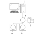
- FIG. 1 is a hardware configuration diagram showing an outline of a diagnostic support system to which the learning device and the region of interest extraction device according to the first embodiment of the present disclosure are applied.
- the learning device and the region of interest extraction device (hereinafter, represented by the region of interest extraction device) according to the first embodiment, a plurality of three-dimensional image capturing devices 2A, 2B, and The image storage server 3 is connected in a communicable state via the network 4.
- the three-dimensional image capturing devices 2A and 2B are devices that generate a three-dimensional image representing the site by photographing the site to be diagnosed of the subject. Specifically, the CT device, the MRI device, and the PET device. (Positron Emission Tomography) Equipment, etc.
- the three-dimensional images generated by the three-dimensional image capturing devices 2A and 2B are transmitted to the image storage server 3 and stored.
- the three-dimensional image capturing device 2A is a CT device
- the three-dimensional image capturing device 2B is an MRI device
- the CT image and the MRI image including the part to be diagnosed of the subject are regarded as three-dimensional images, respectively. Generate.
- the three-dimensional image capturing apparatus 2B shall generate a T1-weighted image and a T2-weighted image as MRI images, respectively.
- the three-dimensional image consists of a plurality of tomographic images. Further, in the present embodiment, the three-dimensional image is obtained by photographing the abdomen of the subject, and the liver included in the abdomen is the region of interest to be extracted.
- the medical image has a different representation format of the image if the acquired modality is different like the CT device and the MRI device.
- the expression format is different between the T1-weighted image and the T2-weighted image.
- T1-weighted images mainly adipose tissue appears white, water, humoral components and cysts appear black, and tumors appear slightly black.
- T2-weighted images not only adipose tissue, but also water, humoral components and cysts appear white. Therefore, the CT image, the T1-weighted image, and the T2-weighted image have different expression formats.
- the expression form corresponds to the domain, and different expression forms are synonymous with different domains.
- the image storage server 3 is a computer that stores and manages various data, and is equipped with a large-capacity external storage device and database management software.
- the image storage server 3 communicates with another device via a wired or wireless network 4 to send and receive image data and the like.
- various data including the image data of the three-dimensional image generated by the three-dimensional image capturing device 2 are acquired via the network and stored in a recording medium such as a large-capacity external storage device for management.
- the storage format of the image data and the communication between the devices via the network 4 are based on a protocol such as DICOM (Digital Imaging and Communication in Medicine).
- DICOM Digital Imaging and Communication in Medicine
- the image storage server 3 also stores and manages images for learning for learning the extraction model described later.
- the region of interest extraction device 1 including the learning device of the present embodiment is one in which the learning program of the first embodiment and the region of interest extraction program are installed on one computer.
- the computer may be a workstation or personal computer operated directly by the diagnosing doctor, or it may be a server computer connected to them via a network.
- the learning program and the region of interest extraction program are stored in the storage device of the server computer connected to the network or in the network storage in a state of being accessible from the outside, and are downloaded and installed on the computer used by the doctor upon request. To. Alternatively, it is recorded and distributed on a recording medium such as a DVD (Digital Versatile Disc) or a CD-ROM (Compact Disc Read Only Memory), and installed on a computer from the recording medium.
- a recording medium such as a DVD (Digital Versatile Disc) or a CD-ROM (Compact Disc Read Only Memory), and installed on a computer from the recording medium.
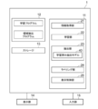
- FIG. 2 is a diagram showing a schematic configuration of an interest region extraction device realized by installing a learning program and an interest region extraction program on a computer.
- the region of interest extraction device 1 includes a CPU (Central Processing Unit) 11, a memory 12, and a storage 13 as a standard workstation configuration. Further, a display unit 14 such as a liquid crystal display and an input unit 15 such as a keyboard and a mouse are connected to the region of interest extraction device 1.
- a CPU Central Processing Unit
- memory 12 main memory
- storage 13 as a standard workstation configuration
- a display unit 14 such as a liquid crystal display
- an input unit 15 such as a keyboard and a mouse are connected to the region of interest extraction device 1.
- the storage 13 is composed of a hard disk drive or the like, and is a target image to be extracted from the image storage server 3 acquired from the image storage server 3 via the network 4, and an image for learning for learning the extraction model 30 as described later. And various information including information necessary for processing is stored.
- the learning program and the region of interest extraction program are stored in the memory 12.
- the learning program acquires a learning image for learning the extraction model, a target image for extracting the region of interest, and various information for learning and extracting the region of interest.
- the information acquisition process to be performed and the learning process to learn the extraction model are defined.
- the interest area extraction program extracts the area of interest included in the target image to be extracted by the information acquisition process, and sets the target image according to the result of extracting the area of interest.
- a labeling process for labeling the included region of interest and a display control process for displaying the labeled target image on the display unit 14 are defined.
- the computer functions as an information acquisition unit 21, a learning unit 22, an extraction unit 23, a labeling unit 24, and a display control unit 25.
- the information acquisition unit 21 acquires a three-dimensional image of the abdomen of the subject as a target image from the image storage server 3 via an interface (not shown) connected to the network.
- an image for learning and a correct answer mask described later are acquired.
- various information for learning by the learning unit 22 is acquired.
- the information for learning is, for example, information on the expression format (that is, the target) after conversion of the image for learning, which will be described later.
- the learning unit 22 learns an extraction model that extracts an area of interest from an image having a plurality of different expression formats.
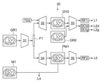
- 3 and 4 are schematic block diagrams showing the configuration of the extraction model according to the first embodiment.
- the extraction model 30 has an encoder 31, a first decoder 32, a first discriminator 33, a second decoder 34, and a second discriminator 35.
- the encoder 31, the first decoder 32, and the first discriminator 33 included in the extraction model 30 form a domain conversion network for converting the representation format of the input image, that is, for converting the domain.
- the encoder 31, the second decoder 34, and the second discriminator 35 included in the extraction model 30 form a region extraction network for extracting the region of interest from the input image.
- the encoder 31 is shared in the domain conversion network and the area extraction network.
- the domain conversion network constitutes a hostile generation network (Generative Adversarial Networks: GAN).
- GAN includes a "Generator” that creates data and a "Discriminator” that identifies the data.
- the combination of the encoder 31 and the first decoder 32 corresponds to the generator, and the first discriminator 33 corresponds to the discriminator.
- the area extraction network also constitutes a hostile generation network
- the combination of the encoder 31 and the second decoder 34 corresponds to the generator
- the second discriminator 35 corresponds to the discriminator
- the encoder 31 is composed of a convolutional neural network (CNN), which is one of a multi-layer neural network in which a plurality of processing layers are hierarchically connected, and provides a feature map representing a feature amount of an input image. Derived. Specifically, as shown in FIG. 3, the encoder 31 derives a feature map F1 representing the feature amount of the first image GR1 when the first image GR1 of the first expression format is input.
- the first image GR1 is an actual image (actual image) generated by the three-dimensional image capturing devices 2A and 2B.
- a convolutional neural network consists of multiple convolutional layers.
- the convolution layer performs convolution processing using various kernels on the input image, and outputs a feature map consisting of feature data obtained by the convolution processing.
- the number of channels of the first convolution layer (that is, the input layer) is 48 or more, but the number is not limited to this.
- the convolution layer applies the kernel to the entire input image or feature map output from the previous processing layer, shifting the pixels of interest of the kernel.
- the convolution layer applies an activation function such as a sigmoid function to the convolution value, and outputs the feature map F1.
- an activation function such as a sigmoid function
- the kernel is applied to the input image or feature map while being shifted by two or more strides during the convolutional process.
- a plurality of types of images having different expression formats that is, different domains, such as CT images, T1-weighted images, and T2-weighted images, are used for learning the extraction model 30.
- a label indicating the expression format is given to the input image as a class label.
- the first image GR1 shown in FIG. 3 is given a class label representing the expression format class of the first image GR1.
- the images used during learning are prepared with and without a correct mask.
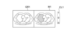
- FIG. 5 is a diagram showing an example of the first image GR1 having the correct answer mask M1
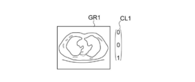
- FIG. 6 is a diagram showing an example of the first image GR1 having no correct answer mask.
- the first image GR1 shown in FIGS. 5 and 6 is given the class label CL1.
- the class label CL1 is a vector having three elements for identifying the classes of the three expression formats, and the element to which 1 is assigned represents the expression format of the image.
- the three elements are a CT image, a T1-weighted image, and a T2-weighted image from the top.
- the expression format is a CT image.
- the expression format is a T2-weighted image.
- the expression format given to the input image is used as the first expression format.
- the first decoder 32 derives a virtual image by converting the first expression format of the input image into a second expression format different from the first expression format based on the feature map. That is, as shown in FIG. 3, when the feature map F1 of the first image GR1 is input, the first decoder 32 changes the first expression format of the first image GR1 to a different expression format from the first expression format.
- the second virtual image GV2 is derived by converting to the expression format of 2.
- the first expression format corresponds to the source domain that is the conversion source
- the second expression format corresponds to the target domain that is the conversion destination.
- the information TD2 of the target domain which is the second expression format, is input to the first decoder 32.
- the second expression format is input from, for example, the input unit 15.
- the information TD2 of the second expression form is a vector representing the class label of the second expression form, and has three elements like the class label CL1.
- the first decoder 32 has a plurality of deconvolution layers.
- the deconvolution layer performs the same processing as the deconvolution layer of the encoder 31, but applies the kernel for the deconvolution calculation to the feature map while upsampling the input feature map.
- the first decoder 32 increases the resolution of the feature map F1 output by the encoder 31 so as to have the resolution of the first image GR1, and expresses the first image GR1. Is converted into the second expression format, and the second virtual image GV2 in the second expression format is derived.
- the first discriminator 33 is composed of, for example, a convolutional neural network, and determines the representation format of the input image and whether the input image is a real image or a virtual image generated by the first decoder 32. , The first determination result is output.
- the first determination result includes the determination result RF1 as to whether the input image is a real image or a virtual image.
- the first discrimination result includes the discrimination result DC1 of the expression format of the input image.
- the real image is not an image generated by the first decoder 32, but an image generated by the three-dimensional image generators 2A and 2B, so to speak, a real image.
- the discrimination result RF1 is correct, and when it is determined to be a virtual image, the discrimination result RF1 is not. The answer is correct. Further, when the first discriminator 33 determines that the input virtual image is a real image, the discrimination result RF1 is an incorrect answer, and when it is determined to be a virtual image, the discrimination result RF1 is a correct answer. Is. In the present embodiment, as shown in FIG. 3, when the second virtual image GV2 is input to the first discriminator 33 at the time of learning, if the discrimination result RF1 is a virtual image, the discrimination result RF1 is correct.
- the learning unit 22 derives the loss based on the discrimination result RF1 output by the first discriminator 33. This loss is called adversarial loss.
- the adversarial loss in the first discriminator 33 is defined as the first loss L1.
- the determination result DC1 is correct and is determined to be other than the CT image. If so, the determination result DC1 is incorrect. Further, when the expression format of the input image is a T2-weighted image and the first discriminator 33 determines that the expression format is a T2-weighted image, the discrimination result DC1 is the correct answer and the T2-weighted image. If it is determined to be other than, the determination result DC1 is incorrect.
- the second image GR2 which is a real image, is input to the first discriminator 33.
- the virtual image derived by the first decoder 32 is input to the first discriminator 33, and the discrimination result DC1 is obtained. It is output.
- the second virtual image GV2 is generated using the T2-weighted image as the second expression format. Therefore, when the second virtual image GV2 which is a T2-weighted image is input to the first discriminator 33 and the discrimination result DC1 is a T2-weighted image, the discrimination result DC1 is a correct answer and is other than the T2-weighted image. In the case of the CT image or the T1-weighted image, the discrimination result DC1 is incorrect.
- the discrimination result DC1 output from the first discriminator 33 is referred to as the discrimination result DC1d, and for the learning of the encoder 31 and the first decoder 32.
- the discrimination result DC1 output from the first discriminator 33 is referred to as a discrimination result DC1g.
- the learning unit 22 derives the loss based on the discrimination results DC1d and DC1g output by the first discriminator 33. This loss is called classification loss.
- the classification loss derived based on the discrimination results DC1d and DC1g is defined as the second loss L2d and L2g, respectively.
- the discrimination results DC1d and DC1g may be represented by the discrimination result DC1
- the second losses L2d and L2g may be represented by the second loss L2.
- the second virtual image GV2 is input to the encoder 31, the feature map F1 derived by the encoder 31 is input to the first decoder 32, and further to the first decoder 32.
- the information TD1 in the first expression format of the first image GR1 is input.
- the first decoder 32 derives the first virtual image GV1. It is desirable that the first virtual image GV1 derived in this way completely matches the first image GR1, but since it has undergone processing by the encoder 31 and the first decoder 32, the first virtual image GV1 and the first virtual image GV1 There is a difference from one image GR1.
- the learning unit 22 derives the difference between the first virtual image GV1 and the first image GR1 as a loss. This loss is called cycle loss.
- the cycle loss is defined as the third loss L3.
- the learning unit 22 correctly answers the determination result RF1 of whether the input image is a real image or a virtual image generated by the first decoder 32, and represents the input image.
- the first discriminator 33 is learned so that the format determination result DC1d is correctly answered. That is, the first discriminator 33 is learned so as to maximize the first loss L1 and minimize the second loss L2d. Specifically, the first discriminator 33 is learned so that ⁇ L1 + L2d is equal to or less than a predetermined threshold value.
- the learning unit 22 derives a virtual image of the specified expression format from the input image, and the first discriminator 33 sets the discrimination result RF1 as an incorrect answer and corrects the discrimination result DC1g.
- the decoder 32 is learned. Further, the learning unit 22 learns the encoder 31 so that the first discriminator 33 sets the discrimination result RF1 as an incorrect answer and derives a feature map F1 that can generate a virtual image that correctly answers the discrimination result DC1. That is, the encoder 31 and the first decoder 32 are learned so as to minimize the first loss L1 and the second loss L2g. Specifically, the encoder 31 and the first decoder 32 are learned so that L1 + L2g is equal to or less than a predetermined threshold value.
- the learning unit 22 learns the first decoder 32 so that the first virtual image GV1 generated from the second virtual image GV2 matches the first image GR1. Further, the learning unit 22 learns the encoder 31 so as to derive the feature map F1 from which the first decoder 32 can derive the first virtual image GV1 that matches the first image GR1. That is, the encoder 31 and the first decoder 32 are learned so as to minimize the third loss L3. Specifically, the encoder 31 and the first decoder 32 are learned so that L3 is equal to or less than a predetermined threshold value.
- the encoder 31, the first decoder 32, and the first discriminator 33 improve the accuracy, and the first discriminator 33 is a real image or a virtual image regardless of the input format of the image. It becomes possible to discriminate whether it is an image with higher accuracy.
- the encoder 31 and the first decoder 32 can generate a virtual image closer to an image in a real expression format, which is not discriminated by the first discriminator 33.
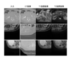
- FIG. 7 is a diagram showing an input real image expression format and a converted virtual image expression format.
- the left column is an input real image
- the expression formats are CT image, T1-weighted image, and T1-weighted image in order from the top.
- the second to fourth columns from the left show the converted virtual image in the representation format.
- the expression formats are a CT image, a T1-weighted image, and a T2-weighted image, respectively, in order from the second column on the left side. According to the present embodiment, as shown in FIG. 7, a virtual image close to the instructed expression format is generated regardless of the expression format of the input real image.
- the second decoder 34 extracts the region of interest of the image input to the encoder 31 by using the feature map derived by the encoder 31.
- the feature map F1 of the first image GR1 is used to extract the region of interest of the first image GR1.
- the second decoder 34 is composed of a convolutional neural network having a plurality of deconvolution layers.
- the second decoder 34 is a region of interest (liver in the present embodiment) included in the first image GR1 while increasing the resolution of the feature map F1 output by the encoder 31 to the resolution of the first image GR1.
- the process of deriving the probability of this and extracting the pixels whose probability is equal to or greater than the threshold value as the region of interest is performed.
- the second decoder 34 outputs the liver extraction result PM1 in the first image GR1.
- the learning unit 22 derives the difference between the extraction result PM1 of the region of interest output by the second decoder 34 and the correct mask M1 as a loss, as shown in FIG. To do.
- This loss is called task loss.
- the task loss is defined as the fourth loss L4.
- the second discriminator 35 is composed of, for example, a convolutional neural network, and whether the extraction result PM1 of the region of interest by the second decoder 34 is the extraction result of the first image GR1 with the correct mask M1 as shown in FIG. It is determined whether it is the extraction result of the first image GR1 without the correct answer mask as shown in FIG. 6, and the second determination result RF2 is output.
- the second discriminator 35 determines that the correct answer mask is present, the second discriminator 35 is present.
- the determination result RF2 is a correct answer, and when it is determined that there is no correct answer mask, the second determination result RF2 is an incorrect answer.
- the second determination result RF2 is incorrect. If it is determined that there is no correct answer mask, the second determination result RF2 is the correct answer.
- the learning unit 22 derives the loss based on the output of the second discriminator 35 with respect to the second determination result RF2. This loss is called adversarial loss.
- the adversarial loss in the second discriminator 35 is defined as the fifth loss L5.
- the learning unit 22 correctly answers the second determination result RF2, which is the extraction result of the first image GR1 with the correct answer mask or the extraction result of the first image GR1 without the correct answer mask.
- the second discriminator 35 is learned. That is, the second discriminator 35 is learned so as to maximize the fifth loss L5. Specifically, the second discriminator 35 is learned so that ⁇ L5 is equal to or less than a predetermined threshold value.
- the first image GR1 with the correct answer mask and the first image GR1 without the correct answer mask are alternately used for learning.
- the learning unit 22 learns the second decoder 34 so that the extraction result PM1 and the correct answer mask M1 match when the feature map F1 of the first image GR1 with the correct answer mask M1 is input. Further, the learning unit 22 learns the encoder 31 so as to derive the feature map F1 from which the extraction result PM1 that matches the correct answer mask M1 is obtained. That is, the encoder 31 and the second decoder 34 are learned so as to minimize the fourth loss L4. Specifically, the encoder 31 and the second decoder 34 are learned so that L4 is equal to or less than a predetermined threshold value.
- the learning unit 22 learns the second decoder 34 so that the second discriminator 35 outputs the extraction result PM1 in which the second discrimination result RF2 is an incorrect answer. Further, the learning unit 22 learns the encoder 31 so that the second discriminator 35 derives the feature map F1 that outputs the extraction result PM1 in which the second discrimination result RF2 is an incorrect answer. That is, the encoder 31 and the first decoder 32 are learned so as to minimize the fifth loss L5. Specifically, the encoder 31 and the first decoder 32 are learned so that L5 is equal to or less than a predetermined threshold value.
- the encoder 31, the first decoder 32, and the first discriminator 33 improve the accuracy, and the second discriminator 35 determines whether the input image has a correct answer mask or no correct answer mask. It will be possible to discriminate with high accuracy.
- the encoder 31 and the second decoder 34 are more accurate in their interest because the presence or absence of the correct answer mask is not determined by the second discriminator 35 regardless of whether the image has the correct answer mask or the image without the correct answer mask.
- the area extraction result can be output.
- the learning unit 22 learning the extraction model 30 as described above, the region of interest included in the target image is selected regardless of the expression format of the target image.
- the extraction model 30 to be extracted is constructed.
- the encoder 31 and the second decoder 34 in the trained extraction model 30 are applied to the extraction unit 23 as the trained extraction model 40.
- the extraction unit 23 extracts the region of interest included in the target image by the trained extraction model 40 and outputs the extraction result.
- the labeling unit 24 labels the region of interest included in the target image based on the extraction result of the region of interest output by the extraction unit 23.
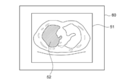
- FIG. 8 is a diagram showing a display screen of the labeled target image. As shown in FIG. 8, the target image 51 is displayed on the display screen 60, and the target image 51 is labeled 52 in the region of interest. Although the labeling 52 is shown by hatching in FIG. 8, the labeling may be performed by changing the color or surrounding with a line.
- FIG. 9 is a flowchart showing the learning process performed in the first embodiment. It is assumed that the first image GR1 for learning and the correct answer mask M1 when there is a correct answer mask are acquired from the image storage server 3 by the information acquisition unit 21 and stored in the storage 13.
- the learning unit 22 acquires the first image GR1 for learning stored in the storage 13 (step ST1).
- the learning unit 22 inputs the first image GR1 to the encoder 31 to derive the feature map F1 (step ST2). Further, the learning unit 22 inputs the feature map F1 and the information TD2 in the second expression format to the first decoder 32, and causes the second virtual image GV2 to be derived (step ST3).
- the learning unit 22 inputs the second image GR2 or the second virtual image GV2 to the first discriminator 33, and outputs the discrimination result RF1 and the discrimination result DC1 which are the first discrimination results (first discrimination result output). , Step ST4).
- the learning unit 22 derives the first loss L1 and the second loss L2 based on the first determination result. Further, the learning unit 22 inputs the second virtual image GV2 to the encoder 31 to derive the feature map of the second virtual image GV2, inputs the feature map of the second virtual image GV2 to the first decoder 32, and secondarily 1 Output the virtual image GV1. Then, the learning unit 22 derives the third loss L3 from the first image GR1 and the first virtual image GV1 (loss derivation; step ST5).
- the learning unit 22 learns the encoder 31, the first decoder 32, and the first discriminator 33 based on the first loss L1, the second loss L2, and the third loss L3 (first learning, step ST6). ..
- the learning unit 22 inputs the feature map F1 to the second decoder 34 and outputs the extraction result PM1 of the region of interest (step ST7). Further, the learning unit 22 inputs the extraction result PM1 to the second discriminator 35 and outputs the second discrimination result RF2 (step ST8). Then, the learning unit 22 derives the fifth loss L5 based on the second determination result RF2. When the first image GR1 has the correct mask M1, the learning unit 22 derives the fourth loss L4 (loss derivation; step ST9).
- the learning unit 22 learns the encoder 31, the second decoder 34, and the second discriminator 35 based on the fourth loss L4 (if any) and the fifth loss L5 (second learning, step ST10). .. Then, the process returns to step ST1, the first image GR1 for the next learning is acquired from the storage 13, and the processes of steps ST1 to ST10 are repeated. As a result, the trained extraction model 30 is constructed.
- the processes of steps ST3 to ST6 and the processes of steps ST7 to ST10 may be performed in parallel, and the processes of steps ST7 to ST10 may be performed before the processes of steps ST3 to ST6.
- the learning unit 22 repeats learning until the various losses L1 to L5 become equal to or less than a predetermined threshold value, the learning unit 22 may repeat learning a predetermined number of times.
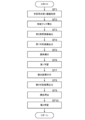
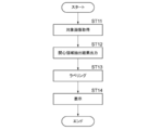
- FIG. 10 is a flowchart of the region of interest extraction process performed in the present embodiment.
- the information acquisition unit 21 acquires the target image (step ST11), and the extraction unit 23 outputs the extraction result of the region of interest included in the target image (step ST12).
- the labeling unit 24 performs labeling 52 of the region of interest included in the target image 51 based on the extraction result of the region of interest (step ST13).
- the display control unit 25 displays the labeled target image on the display unit 14 (step ST14), and ends the process.
- the expression format of the input image and whether the input image is a real image or a virtual image generated by the first decoder 32 are determined, and the first determination result is obtained. Is output. Further, it is determined whether the extraction result PM1 of the region of interest by the second decoder 34 is the extraction result of the first image with the correct answer mask or the extraction result of the first image without the correct answer mask, and the second determination is made. The result is output. Then, the encoder 31, the first decoder 32, and the first discriminator 33 are learned based on the first discrimination result, and the encoder 31, the second decoder 34, and the second discriminator 35 are learned based on the second discrimination result. I tried to learn.
- the encoder 31, the first decoder 32, and the first discriminator 33 improve the accuracy, and the first discriminator 33 inputs an image in any expression format. Even if it is done, it will be possible to distinguish between a real image and a virtual image with higher accuracy. Further, the encoder 31 and the first decoder 32 can generate a virtual image closer to an image in a real expression format, which is not discriminated by the first discriminator 33. Further, the encoder 31, the first decoder 32, and the first discriminator 33 enhance the accuracy of each other, and the second discriminator 35 makes the input image more accurate whether the input image has the correct answer mask or not. You will be able to distinguish. Further, the encoder 31 and the second decoder 34 are more accurate in that the presence or absence of the correct answer mask is not determined by the second discriminator 35 regardless of whether the image has the correct answer mask or the image without the correct answer mask. The area extraction result can be output.
- the trained extraction model 40 having the trained encoder 31 and the second decoder 34, it is not patentable without preparing a model for each expression format as in the method described in Non-Patent Document 2.
- the region of interest contained in the target image can be extracted regardless of the expression format of the target image without inputting the domain label at the time of extraction.
- FIG. 11 is a schematic block diagram showing the configuration of the extraction model according to the second embodiment.
- the extraction model 30A in the second embodiment is different from the first embodiment in that it includes a third discriminator 36 instead of the second discriminator 35.
- the encoder 31 and the third discriminator 36 form a GAN. Since the learning of the first decoder 32, the first discriminator 33, and the second decoder 34 is the same as that of the first embodiment, detailed description thereof will be omitted here.
- the third discriminator 36 is composed of, for example, a convolutional neural network, determines the representation format of the input image based on the feature map output by the encoder 31, and outputs the third discrimination result DC2. That is, as shown in FIG. 11, the third discriminator 36 determines from which representation format the feature map F1 of the first image GR1 derived by the encoder 31 is derived from the third image.
- the determination result DC2 is output. For example, when the expression format of the input image is a CT image and the third discriminator 36 determines that it is a CT image, the third determination result DC2 is the correct answer and it is determined that it is not a CT image. The third determination result DC2 is incorrect.
- the third discrimination result DC2 is a T2-weighted image
- the third discrimination result DC2 is a correct answer
- a CT image other than the T2-weighted image or T1-weighted image is used.
- the third determination result DC2 is an incorrect answer.
- the learning unit 22 derives the loss based on the output of the third discriminator 36 with respect to the third determination result DC2. This loss is called classification loss.
- the classification loss is defined as the sixth loss L6.
- the learning unit 22 learns the third discriminator 36 so as to correctly answer the third discrimination result DC2 of the input image expression format. Further, the learning unit 22 learns the encoder 31 so that the third discriminator 36 derives the feature map F1 in which the third determination result DC2 is an incorrect answer. That is, the encoder 31 and the third discriminator 36 are learned so as to minimize the first loss L1 and the sixth loss L6. Specifically, the encoder 31 and the third discriminator 36 are learned so that L1 + L6 are equal to or less than a predetermined threshold value.
- the encoder 31 and the third discriminator 36 improve the accuracy, and the third discriminator 36 can discriminate the expression format with higher accuracy no matter what kind of image is input. Become.
- the encoder 31 can generate the same feature map F1 regardless of the expression format, which is not discriminated by the third discriminator 36 no matter what kind of image is input.
- the second decoder 34 can extract the region of interest regardless of the expression format of the image input to the extraction model 30A.
- the expression format of the input image and whether the input image is a real image or a virtual image generated by the first decoder 32 are determined and the first determination is made.
- the result is output, the expression format of the input image is discriminated based on the feature map F1 derived by the encoder 31, and the third discriminant result is output.
- the encoder 31, the first decoder 32, and the first discriminator 33 are learned based on the first discrimination result, and the encoder 31 and the third discriminator 36 are learned based on the third discrimination result. did. Therefore, as in the first embodiment, the region of interest included in the target image can be extracted regardless of the expression format of the target image.
- the third discriminator 36 may be provided without omitting the second discriminator 35 as in the extraction model 30B shown in FIG.
- the encoder 31 and the second decoder 34 included in the trained extraction models 30A and 30B are used as the trained extraction model 40.
- the region of interest is extracted from the three-dimensional image of the abdomen of the human body, but the present invention is not limited to this.
- the technique of the present disclosure can be applied to extraction of a region of interest from a simple X-ray image, an ultrasonic image, or the like, in addition to a three-dimensional image such as a CT image or an MRI image.
- a T1-weighted image and a T2-weighted image are used as the MRI image, but the MRI image is not limited to this.
- the MRI image may include at least one expression format of a diffusion-weighted image, a FLAIR image, a pre-contrast T1-weighted image, and a post-contrast-enhanced T1-weighted image, in addition to the T1-weighted image and the T2-weighted image.
- the liver is extracted as an area of interest, but the present invention is not limited to this.
- the techniques of the present disclosure can also be applied when extracting regions of various structures in the human body such as lungs, heart, kidneys and brain as regions of interest.
- a hardware structure of a processing unit that executes various processes such as an information acquisition unit 21, a learning unit 22, an extraction unit 23, a labeling unit 24, and a display control unit 25.
- various processors processors shown below can be used.
- the various processors include a CPU, which is a general-purpose processor that executes software (program) and functions as various processing units, and a circuit after manufacturing an FPGA (Field Programmable Gate Array) or the like.
- Dedicated electricity which is a processor with a circuit configuration specially designed to execute specific processing such as programmable logic device (PLD), ASIC (Application Specific Integrated Circuit), which is a processor whose configuration can be changed. Circuits and the like are included.
- One processing unit may be composed of one of these various processors, or a combination of two or more processors of the same type or different types (for example, a combination of a plurality of FPGAs or a combination of a CPU and an FPGA). ) May be configured. Further, a plurality of processing units may be configured by one processor.
- one processor is configured by a combination of one or more CPUs and software, as represented by a computer such as a client and a server. There is a form in which this processor functions as a plurality of processing units.
- SoC System On Chip
- the various processing units are configured by using one or more of the various processors as a hardware structure.
- circuitry in which circuit elements such as semiconductor elements are combined can be used.
Landscapes
- Engineering & Computer Science (AREA)
- Health & Medical Sciences (AREA)
- Life Sciences & Earth Sciences (AREA)
- Physics & Mathematics (AREA)
- Medical Informatics (AREA)
- Theoretical Computer Science (AREA)
- Computer Vision & Pattern Recognition (AREA)
- Multimedia (AREA)
- General Physics & Mathematics (AREA)
- General Health & Medical Sciences (AREA)
- Public Health (AREA)
- High Energy & Nuclear Physics (AREA)
- Biomedical Technology (AREA)
- Heart & Thoracic Surgery (AREA)
- Molecular Biology (AREA)
- Surgery (AREA)
- Animal Behavior & Ethology (AREA)
- Pathology (AREA)
- Nuclear Medicine, Radiotherapy & Molecular Imaging (AREA)
- Veterinary Medicine (AREA)
- Optics & Photonics (AREA)
- Radiology & Medical Imaging (AREA)
- Biophysics (AREA)
- Artificial Intelligence (AREA)
- Computing Systems (AREA)
- Databases & Information Systems (AREA)
- Evolutionary Computation (AREA)
- Software Systems (AREA)
- Image Analysis (AREA)
- Apparatus For Radiation Diagnosis (AREA)
- Magnetic Resonance Imaging Apparatus (AREA)
Abstract
Description
非特許文献2:Judy Hoffman, Eric Tzeng, Taesung Park, Jun-Yan Zhu, Phillip Isola, Kate Saenko, Alexei A. Efros, Trevor Darrell "CyCADA: Cycle-Consistent Adversarial Domain Adaptation", arXiv:1711.03213
非特許文献3:Yunjey Choi, Minje Choi, Munyoung Kim, Jung-Woo Ha, Sunghun Kim, Jaegul Choo "StarGAN: Unified Generative Adversarial Networks for Multi-Domain Image-to-Image Translation",arXiv:1711.09020
抽出モデルは、
第1の表現形式の第1画像の特徴量を抽出することにより、第1画像の特徴マップを導出するエンコーダ、
特徴マップに基づいて、第1画像の表現形式とは異なる第2の表現形式の第2仮想画像を導出する第1デコーダ、
入力された画像の表現形式および入力された画像が実画像であるか第1デコーダにより生成された仮想画像であるかを判別して第1判別結果を出力する第1ディスクリミネータ、
特徴マップに基づいて、第1画像の関心領域を抽出する第2デコーダ、および
第2デコーダによる関心領域の抽出結果が、正解マスク有りの第1画像の抽出結果であるか、正解マスク無しの第1画像の抽出結果であるかを判別して、第2判別結果を出力する第2ディスクリミネータを有し、
第1判別結果に基づいて、エンコーダ、第1デコーダおよび第1ディスクリミネータを学習し、第2判別結果に基づいて、エンコーダ、第2デコーダおよび第2ディスクリミネータを学習する学習部を備える。
第1デコーダに、第2仮想画像の特徴マップに基づいて、第1の表現形式の第1仮想画像を導出させ、
第1画像および第1仮想画像との相違にも基づいて、エンコーダ、第1デコーダおよび第1ディスクリミネータを学習するものであってもよい。
学習部は、第3判別結果に基づいて、エンコーダおよび第3ディスクリミネータを学習するものであってもよい。
抽出モデルは、
第1の表現形式の第1画像の特徴量を抽出することにより、第1画像の特徴マップを導出するエンコーダ、
特徴マップに基づいて、第1画像の表現形式とは異なる第2の表現形式の第2仮想画像を導出する第1デコーダ、
入力された画像の表現形式および入力された画像が実画像であるか第1デコーダにより生成された仮想画像であるかを判別して第1判別結果を出力する第1ディスクリミネータ、
特徴マップに基づいて、第1画像の関心領域を抽出する第2デコーダ、および
特徴マップに基づいて、エンコーダに入力された第1画像の表現形式を判別して第3判別結果を出力する第3ディスクリミネータを有し、
第1判別結果に基づいて、エンコーダ、第1デコーダおよび第1ディスクリミネータを学習し、第3判別結果に基づいて、エンコーダおよび第3ディスクリミネータを学習する学習部を備える。
抽出モデルは、
第1の表現形式の第1画像の特徴量を抽出することにより、第1画像の特徴マップを導出するエンコーダ、
特徴マップに基づいて、第1画像の表現形式とは異なる第2の表現形式の第2仮想画像を導出する第1デコーダ、
入力された画像の表現形式および入力された画像が実画像であるか第1デコーダにより生成された仮想画像であるかを判別して第1判別結果を出力する第1ディスクリミネータ、
特徴マップに基づいて、第1画像の関心領域を抽出する第2デコーダ、および
第2デコーダによる関心領域の抽出結果が、正解マスク有りの第1画像の抽出結果であるか、正解マスク無しの第1画像の抽出結果であるかを判別して、第2判別結果を出力する第2ディスクリミネータを有し、
第1判別結果に基づいて、エンコーダ、第1デコーダおよび第1ディスクリミネータを学習し、
第2判別結果に基づいて、エンコーダ、第2デコーダおよび第2ディスクリミネータを学習する。
抽出モデルは、
第1の表現形式の第1画像の特徴量を抽出することにより、第1画像の特徴マップを導出するエンコーダ、
特徴マップに基づいて、第1画像の表現形式とは異なる第2の表現形式の第2仮想画像を導出する第1デコーダ、
入力された画像の表現形式および入力された画像が実画像であるか第1デコーダにより生成された仮想画像であるかを判別して第1判別結果を出力する第1ディスクリミネータ、
特徴マップに基づいて、第1画像の関心領域を抽出する第2デコーダ、および
特徴マップに基づいて、エンコーダに入力された第1画像の表現形式を判別して第3判別結果を出力する第3ディスクリミネータを有し、
第1判別結果に基づいて、エンコーダ、第1デコーダおよび第1ディスクリミネータを学習し、
第3判別結果に基づいて、エンコーダおよび第3ディスクリミネータを学習する。
コンピュータに実行させるための命令を記憶するメモリと、
記憶された命令を実行するよう構成されたプロセッサとを備え、
抽出モデルは、
第1の表現形式の第1画像の特徴量を抽出することにより、第1画像の特徴マップを導出するエンコーダ、
特徴マップに基づいて、第1画像の表現形式とは異なる第2の表現形式の第2仮想画像を導出する第1デコーダ、
入力された画像の表現形式および入力された画像が実画像であるか第1デコーダにより生成された仮想画像であるかを判別して第1判別結果を出力する第1ディスクリミネータ、
特徴マップに基づいて、第1画像の関心領域を抽出する第2デコーダ、および
第2デコーダによる関心領域の抽出結果が、正解マスク有りの第1画像の抽出結果であるか、正解マスク無しの第1画像の抽出結果であるかを判別して、第2判別結果を出力する第2ディスクリミネータを有し、
プロセッサは、
第1判別結果に基づいて、エンコーダ、第1デコーダおよび第1ディスクリミネータを学習し、第2判別結果に基づいて、エンコーダ、第2デコーダおよび第2ディスクリミネータを学習する処理を実行する。
コンピュータに実行させるための命令を記憶するメモリと、
記憶された命令を実行するよう構成されたプロセッサとを備え、
抽出モデルは、
第1の表現形式の第1画像の特徴量を抽出することにより、第1画像の特徴マップを導出するエンコーダ、
特徴マップに基づいて、第1画像の表現形式とは異なる第2の表現形式の第2仮想画像を導出する第1デコーダ、
入力された画像の表現形式および入力された画像が実画像であるか第1デコーダにより生成された仮想画像であるかを判別して第1判別結果を出力する第1ディスクリミネータ、
特徴マップに基づいて、第1画像の関心領域を抽出する第2デコーダ、および
特徴マップに基づいて、エンコーダに入力された第1画像の表現形式を判別して第3判別結果を出力する第3ディスクリミネータを有し、
プロセッサは、
第1判別結果に基づいて、エンコーダ、第1デコーダおよび第1ディスクリミネータを学習し、第3判別結果に基づいて、エンコーダおよび第3ディスクリミネータを学習する処理を実行する。
記憶された命令を実行するよう構成されたプロセッサとを備え、プロセッサは、
本開示による第1または第2の学習方法により学習された抽出モデルにおけるエンコーダおよび第2デコーダとして機能し、任意の表現形式の画像から画像の関心領域を抽出する処理を実行する。
2 3次元画像撮影装置
3 画像保管サーバ
4 ネットワーク
11 CPU
12 メモリ
13 ストレージ
14 ディスプレイ
15 入力部
21 情報取得部
22 学習部
23 抽出部
24 ラベリング部
25 表示制御部
30,30A,30B 抽出モデル
31 エンコーダ
32 第1デコーダ
33 第1ディスクリミネータ
34 第2デコーダ
35 第2ディスクリミネータ
36 第3ディスクリミネータ
40 学習済み抽出モデル
51 対象画像
52 ラベリング
60 表示画面
DC1,DC2d,DC2g,DC3,RF1,RF2 判別結果
F1 特徴マップ
GR1 第1画像
GR2 第2画像
GV1 第1仮想画像
GV2 第2仮想画像
L1~L6 損失
M1 正解マスク
PM1 抽出結果
Claims (15)
- 複数の異なる表現形式を有する画像から関心領域を抽出する抽出モデルの学習装置であって、
前記抽出モデルは、
第1の表現形式の第1画像の特徴量を抽出することにより、前記第1画像の特徴マップを導出するエンコーダ、
前記特徴マップに基づいて、前記第1画像の表現形式とは異なる第2の表現形式の第2仮想画像を導出する第1デコーダ、
入力された画像の表現形式および前記入力された画像が実画像であるか前記第1デコーダにより生成された仮想画像であるかを判別して第1判別結果を出力する第1ディスクリミネータ、
前記特徴マップに基づいて、前記第1画像の関心領域を抽出する第2デコーダ、および
前記第2デコーダによる前記関心領域の抽出結果が、正解マスク有りの第1画像の抽出結果であるか、正解マスク無しの第1画像の抽出結果であるかを判別して、第2判別結果を出力する第2ディスクリミネータを有し、
前記第1判別結果に基づいて、前記エンコーダ、前記第1デコーダおよび前記第1ディスクリミネータを学習し、前記第2判別結果に基づいて、前記エンコーダ、第2デコーダおよび前記第2ディスクリミネータを学習する学習部を備えた学習装置。 - 前記学習部は、前記エンコーダに前記第2仮想画像を入力して該第2仮想画像の特徴マップを導出させ、
前記第1デコーダに、前記第2仮想画像の特徴マップに基づいて、前記第1の表現形式の第1仮想画像を導出させ、
前記第1画像および前記第1仮想画像との相違にも基づいて、前記エンコーダ、前記第1デコーダおよび前記第1ディスクリミネータを学習する請求項1に記載の学習装置。 - 前記第1画像が前記関心領域についての正解マスクを有する場合、前記学習部は、前記関心領域の抽出結果および前記正解マスクに基づいて、前記第2デコーダを学習する請求項1または2に記載の学習装置。
- 前記抽出モデルは、前記特徴マップに基づいて、前記エンコーダに入力された前記第1画像の表現形式を判別して第3判別結果を出力する第3ディスクリミネータをさらに有し、
前記学習部は、前記第3判別結果に基づいて、前記エンコーダおよび前記第3ディスクリミネータを学習する請求項1から3のいずれか1項に記載の学習装置。 - 複数の異なる表現形式を有する画像から関心領域を抽出する抽出モデルの学習装置であって、
前記抽出モデルは、
第1の表現形式の第1画像の特徴量を抽出することにより、前記第1画像の特徴マップを導出するエンコーダ、
前記特徴マップに基づいて、前記第1画像の表現形式とは異なる第2の表現形式の第2仮想画像を導出する第1デコーダ、
入力された画像の表現形式および前記入力された画像が実画像であるか前記第1デコーダにより生成された仮想画像であるかを判別して第1判別結果を出力する第1ディスクリミネータ、
前記特徴マップに基づいて、前記第1画像の関心領域を抽出する第2デコーダ、および
前記特徴マップに基づいて、前記エンコーダに入力された前記第1画像の表現形式を判別して第3判別結果を出力する第3ディスクリミネータを有し、
前記第1判別結果に基づいて、前記エンコーダ、前記第1デコーダおよび前記第1ディスクリミネータを学習し、前記第3判別結果に基づいて、前記エンコーダおよび前記第3ディスクリミネータを学習する学習部を備えた学習装置。 - 前記画像は3次元の医用画像であり、前記表現形式は、CT画像およびMRI画像の表現形式を含む請求項1から5のいずれか1項に記載の学習装置。
- 前記表現形式は、MRI画像における、T1強調画像、T2強調画像、拡散強調画像、FLAIR画像、造影前T1強調画像、および造影後T1強調画像の少なくとも1つの表現形式を含む請求項6に記載の学習装置。
- 請求項1から7のいずれか1項に記載の学習装置により学習された抽出モデルにおけるエンコーダおよび第2デコーダを有し、任意の表現形式の画像から該画像の関心領域を抽出する抽出部を備えた関心領域抽出装置。
- 請求項1から7のいずれか1項に記載の学習装置により学習された抽出モデルにおけるエンコーダおよび第2デコーダを備えた学習済み抽出モデル。
- 複数の異なる表現形式を有する画像から関心領域を抽出する抽出モデルの学習方法であって、
前記抽出モデルは、
第1の表現形式の第1画像の特徴量を抽出することにより、前記第1画像の特徴マップを導出するエンコーダ、
前記特徴マップに基づいて、前記第1画像の表現形式とは異なる第2の表現形式の第2仮想画像を導出する第1デコーダ、
入力された画像の表現形式および前記入力された画像が実画像であるか前記第1デコーダにより生成された仮想画像であるかを判別して第1判別結果を出力する第1ディスクリミネータ、
前記特徴マップに基づいて、前記第1画像の関心領域を抽出する第2デコーダ、および
前記第2デコーダによる前記関心領域の抽出結果が、正解マスク有りの第1画像の抽出結果であるか、正解マスク無しの第1画像の抽出結果であるかを判別して、第2判別結果を出力する第2ディスクリミネータを有し、
前記第1判別結果に基づいて、前記エンコーダ、前記第1デコーダおよび前記第1ディスクリミネータを学習し、
前記第2判別結果に基づいて、前記エンコーダ、第2デコーダおよび前記第2ディスクリミネータを学習する学習方法。 - 複数の異なる表現形式を有する画像から関心領域を抽出する抽出モデルの学習方法であって、
前記抽出モデルは、
第1の表現形式の第1画像の特徴量を抽出することにより、前記第1画像の特徴マップを導出するエンコーダ、
前記特徴マップに基づいて、前記第1画像の表現形式とは異なる第2の表現形式の第2仮想画像を導出する第1デコーダ、
入力された画像の表現形式および前記入力された画像が実画像であるか前記第1デコーダにより生成された仮想画像であるかを判別して第1判別結果を出力する第1ディスクリミネータ、
前記特徴マップに基づいて、前記第1画像の関心領域を抽出する第2デコーダ、および
前記特徴マップに基づいて、前記エンコーダに入力された前記第1画像の表現形式を判別して第3判別結果を出力する第3ディスクリミネータを有し、
前記第1判別結果に基づいて、前記エンコーダ、前記第1デコーダおよび前記第1ディスクリミネータを学習し、
前記第3判別結果に基づいて、前記エンコーダおよび前記第3ディスクリミネータを学習する学習方法。 - 請求項10または11に記載の学習方法により学習された抽出モデルにおけるエンコーダおよび第2デコーダを有し、任意の表現形式の画像から該画像の関心領域を抽出する関心領域抽出方法。
- 複数の異なる表現形式を有する画像から関心領域を抽出する抽出モデルの学習方法をコンピュータに実行させる学習プログラムであって、
前記抽出モデルは、
第1の表現形式の第1画像の特徴量を抽出することにより、前記第1画像の特徴マップを導出するエンコーダ、
前記特徴マップに基づいて、前記第1画像の表現形式とは異なる第2の表現形式の第2仮想画像を導出する第1デコーダ、
入力された画像の表現形式および前記入力された画像が実画像であるか前記第1デコーダにより生成された仮想画像であるかを判別して第1判別結果を出力する第1ディスクリミネータ、
前記特徴マップに基づいて、前記第1画像の関心領域を抽出する第2デコーダ、および
前記第2デコーダによる前記関心領域の抽出結果が、正解マスク有りの第1画像の抽出結果であるか、正解マスク無しの第1画像の抽出結果であるかを判別して、第2判別結果を出力する第2ディスクリミネータを有し、
前記第1判別結果に基づいて、前記エンコーダ、前記第1デコーダおよび前記第1ディスクリミネータを学習する手順と、
前記第2判別結果に基づいて、前記エンコーダ、第2デコーダおよび前記第2ディスクリミネータを学習する手順とをコンピュータに実行させる学習プログラム。 - 複数の異なる表現形式を有する画像から関心領域を抽出する抽出モデルの学習方法をコンピュータに実行させる学習プログラムであって、
前記抽出モデルは、
第1の表現形式の第1画像の特徴量を抽出することにより、前記第1画像の特徴マップを導出するエンコーダ、
前記特徴マップに基づいて、前記第1画像の表現形式とは異なる第2の表現形式の第2仮想画像を導出する第1デコーダ、
入力された画像の表現形式および前記入力された画像が実画像であるか前記第1デコーダにより生成された仮想画像であるかを判別して第1判別結果を出力する第1ディスクリミネータ、
前記特徴マップに基づいて、前記第1画像の関心領域を抽出する第2デコーダ、および
前記特徴マップに基づいて、前記エンコーダに入力された前記第1画像の表現形式を判別して第3判別結果を出力する第3ディスクリミネータを有し、
前記第1判別結果に基づいて、前記エンコーダ、前記第1デコーダおよび前記第1ディスクリミネータを学習する手順と、
前記第3判別結果に基づいて、前記エンコーダおよび前記第3ディスクリミネータを学習する手順とをコンピュータに実行させる学習プログラム。 - 請求項10または11に記載の学習方法により学習された抽出モデルにおけるエンコーダおよび第2デコーダを有し、任意の表現形式の画像から該画像の関心領域を抽出する手順をコンピュータに実行させる関心領域抽出プログラム。
Priority Applications (3)
| Application Number | Priority Date | Filing Date | Title |
|---|---|---|---|
| EP20844578.3A EP4006830B1 (en) | 2019-07-25 | 2020-07-22 | Learning device, method, and program, region of interest extracting device, method, and program, and learned extraction model |
| JP2021534066A JP7203978B2 (ja) | 2019-07-25 | 2020-07-22 | 学習装置、方法およびプログラム、関心領域抽出装置、方法およびプログラム、並びに学習済み抽出モデル |
| US17/578,465 US12608900B2 (en) | 2019-07-25 | 2022-01-19 | Learning apparatus, learning method, and learning program, region-of-interest extraction apparatus, region-of-interest extraction method, and region-of-interest extraction program, and learned extraction model |
Applications Claiming Priority (2)
| Application Number | Priority Date | Filing Date | Title |
|---|---|---|---|
| JP2019137033 | 2019-07-25 | ||
| JP2019-137033 | 2019-07-25 |
Related Child Applications (1)
| Application Number | Title | Priority Date | Filing Date |
|---|---|---|---|
| US17/578,465 Continuation US12608900B2 (en) | 2019-07-25 | 2022-01-19 | Learning apparatus, learning method, and learning program, region-of-interest extraction apparatus, region-of-interest extraction method, and region-of-interest extraction program, and learned extraction model |
Publications (1)
| Publication Number | Publication Date |
|---|---|
| WO2021015231A1 true WO2021015231A1 (ja) | 2021-01-28 |
Family
ID=74194213
Family Applications (1)
| Application Number | Title | Priority Date | Filing Date |
|---|---|---|---|
| PCT/JP2020/028415 Ceased WO2021015231A1 (ja) | 2019-07-25 | 2020-07-22 | 学習装置、方法およびプログラム、関心領域抽出装置、方法およびプログラム、並びに学習済み抽出モデル |
Country Status (4)
| Country | Link |
|---|---|
| US (1) | US12608900B2 (ja) |
| EP (1) | EP4006830B1 (ja) |
| JP (1) | JP7203978B2 (ja) |
| WO (1) | WO2021015231A1 (ja) |
Cited By (1)
| Publication number | Priority date | Publication date | Assignee | Title |
|---|---|---|---|---|
| CN113077491A (zh) * | 2021-04-02 | 2021-07-06 | 安徽大学 | 基于跨模态共享和特定表示形式的rgbt目标跟踪方法 |
Families Citing this family (4)
| Publication number | Priority date | Publication date | Assignee | Title |
|---|---|---|---|---|
| EP3767536B1 (en) * | 2019-07-17 | 2025-02-19 | Naver Corporation | Latent code for unsupervised domain adaptation |
| US11657292B1 (en) * | 2020-01-15 | 2023-05-23 | Architecture Technology Corporation | Systems and methods for machine learning dataset generation |
| KR102159052B1 (ko) * | 2020-05-12 | 2020-09-23 | 주식회사 폴라리스쓰리디 | 영상 분류 방법 및 장치 |
| CN114581558B (zh) * | 2022-02-25 | 2023-07-07 | 北京百度网讯科技有限公司 | 图像处理方法、装置、设备以及存储介质 |
Citations (2)
| Publication number | Priority date | Publication date | Assignee | Title |
|---|---|---|---|---|
| JP2018192264A (ja) * | 2017-05-18 | 2018-12-06 | キヤノンメディカルシステムズ株式会社 | 医用画像処理装置 |
| US20190220977A1 (en) * | 2018-01-16 | 2019-07-18 | Siemens Healthcare Gmbh | Cross-Domain Image Analysis and Cross-Domain Image Synthesis Using Deep Image-to-Image Networks and Adversarial Networks |
Family Cites Families (2)
| Publication number | Priority date | Publication date | Assignee | Title |
|---|---|---|---|---|
| US10753997B2 (en) * | 2017-08-10 | 2020-08-25 | Siemens Healthcare Gmbh | Image standardization using generative adversarial networks |
| WO2019241659A1 (en) * | 2018-06-15 | 2019-12-19 | Subtle Medical, Inc. | Systems and methods for magnetic resonance imaging standardization using deep learning |
-
2020
- 2020-07-22 EP EP20844578.3A patent/EP4006830B1/en active Active
- 2020-07-22 JP JP2021534066A patent/JP7203978B2/ja active Active
- 2020-07-22 WO PCT/JP2020/028415 patent/WO2021015231A1/ja not_active Ceased
-
2022
- 2022-01-19 US US17/578,465 patent/US12608900B2/en active Active
Patent Citations (2)
| Publication number | Priority date | Publication date | Assignee | Title |
|---|---|---|---|---|
| JP2018192264A (ja) * | 2017-05-18 | 2018-12-06 | キヤノンメディカルシステムズ株式会社 | 医用画像処理装置 |
| US20190220977A1 (en) * | 2018-01-16 | 2019-07-18 | Siemens Healthcare Gmbh | Cross-Domain Image Analysis and Cross-Domain Image Synthesis Using Deep Image-to-Image Networks and Adversarial Networks |
Non-Patent Citations (4)
| Title |
|---|
| IAN J. GOODFELLOWJEAN POUGET-ABADIEMEHDI MIRZABING XUDAVID WARDE-FARLEYSHERJIL OZAIRAARON COURVILLEYOSHUA BENGIO: "Generative Adversarial Nets", ARXIV: 1406.2661 |
| JUDY HOFFMANERIC TZENGTAESUNG PARKJUN-YAN ZHUPHILLIP ISOLAKATE SAENKOALEXEI A. EFROSTREVOR DARRELL: "CyCADA: Cycle-Consistent Adversarial Domain Adaptation", ARXIV: 1711.03213 |
| See also references of EP4006830A4 |
| YUNJEY CHOIMINJE CHOIMUNYOUNG KIMJUNG-WOO HASUNGHUN KIMJAEGUL CHOO: "StarGAN: Unified Generative Adversarial Networks for Multi-Domain Image-to-image Translation", ARXIV: 1711.09020 |
Cited By (1)
| Publication number | Priority date | Publication date | Assignee | Title |
|---|---|---|---|---|
| CN113077491A (zh) * | 2021-04-02 | 2021-07-06 | 安徽大学 | 基于跨模态共享和特定表示形式的rgbt目标跟踪方法 |
Also Published As
| Publication number | Publication date |
|---|---|
| EP4006830A1 (en) | 2022-06-01 |
| EP4006830A4 (en) | 2022-09-28 |
| EP4006830B1 (en) | 2026-03-18 |
| JPWO2021015231A1 (ja) | 2021-01-28 |
| US12608900B2 (en) | 2026-04-21 |
| US20220139062A1 (en) | 2022-05-05 |
| JP7203978B2 (ja) | 2023-01-13 |
Similar Documents
| Publication | Publication Date | Title |
|---|---|---|
| JP7203978B2 (ja) | 学習装置、方法およびプログラム、関心領域抽出装置、方法およびプログラム、並びに学習済み抽出モデル | |
| US12254553B2 (en) | Learning device, learning method, learning program, image generation device, image generation method, image generation program, and image generation model | |
| JP2024150400A (ja) | 医用画像処理装置及び方法 | |
| JP7840661B2 (ja) | 医用画像処理装置、医用画像処理方法、および医用画像処理プログラム | |
| US20200134876A1 (en) | Generating simulated body parts for images | |
| CN110852993B (zh) | 一种造影剂作用下的成像方法与设备 | |
| JP7662654B2 (ja) | 学習装置、方法およびプログラム、画像生成装置、方法およびプログラム、学習済みモデル、仮想画像並びに記録媒体 | |
| JP7765415B2 (ja) | 学習済みモデルの生成方法、機械学習システム、プログラムおよび医療画像処理装置 | |
| JP7795352B2 (ja) | 画像処理方法、画像処理装置およびプログラム | |
| EP4285828B1 (en) | Learned model generation method, machine learning system, program, and medical image processing device | |
| JP2021140769A (ja) | 医用情報処理装置、医用情報処理方法及び医用情報処理プログラム | |
| JP2024155904A (ja) | 画像データ処理装置および方法 | |
| Liu et al. | Decompose to manipulate: Manipulable object synthesis in 3D medical images with structured image decomposition | |
| CN114387259A (zh) | 用于预测缺失牙坐标的方法与装置及识别模型的训练方法 | |
| Li et al. | Anatomy completor: A multi-class completion framework for 3D anatomy reconstruction | |
| Amara et al. | Augmented reality for medical practice: a comparative study of deep learning models for ct-scan segmentation | |
| Athreya et al. | Ultrasound image enhancement using CycleGAN and perceptual loss | |
| WO2020175445A1 (ja) | 学習方法、学習装置、生成モデル及びプログラム | |
| Piao et al. | Segmentation of cysts in kidney and 3-D volume calculation from CT images | |
| Kerfoot et al. | Synthesising images and labels between MR sequence types with CycleGAN | |
| Andreini et al. | Multi-stage synthetic image generation for the semantic segmentation of medical images | |
| Wijethilake et al. | crossMoDA Challenge: Evolution of Cross-Modality Domain Adaptation Techniques for Vestibular Schwannoma and Cochlea Segmentation from 2021 to 2023 | |
| WO2020262681A1 (ja) | 学習装置、方法およびプログラム、医用画像処理装置、方法およびプログラム、並びに判別器 | |
| WO2020246192A1 (ja) | 修正指示領域表示装置、方法およびプログラム | |
| Raza et al. | CycleGAN with mutual information loss constraint generates structurally aligned CT images from functional EIT images |
Legal Events
| Date | Code | Title | Description |
|---|---|---|---|
| 121 | Ep: the epo has been informed by wipo that ep was designated in this application |
Ref document number: 20844578 Country of ref document: EP Kind code of ref document: A1 |
|
| ENP | Entry into the national phase |
Ref document number: 2021534066 Country of ref document: JP Kind code of ref document: A |
|
| NENP | Non-entry into the national phase |
Ref country code: DE |
|
| WWE | Wipo information: entry into national phase |
Ref document number: 2020844578 Country of ref document: EP |
|
| WWG | Wipo information: grant in national office |
Ref document number: 2020844578 Country of ref document: EP |