WO2021020257A1 - 車載電源システム - Google Patents
車載電源システム Download PDFInfo
- Publication number
- WO2021020257A1 WO2021020257A1 PCT/JP2020/028368 JP2020028368W WO2021020257A1 WO 2021020257 A1 WO2021020257 A1 WO 2021020257A1 JP 2020028368 W JP2020028368 W JP 2020028368W WO 2021020257 A1 WO2021020257 A1 WO 2021020257A1
- Authority
- WO
- WIPO (PCT)
- Prior art keywords
- power supply
- electronic devices
- vehicle
- supply system
- power
- Prior art date
- Legal status (The legal status is an assumption and is not a legal conclusion. Google has not performed a legal analysis and makes no representation as to the accuracy of the status listed.)
- Ceased
Links
Images

Classifications
-
- G—PHYSICS
- G05—CONTROLLING; REGULATING
- G05B—CONTROL OR REGULATING SYSTEMS IN GENERAL; FUNCTIONAL ELEMENTS OF SUCH SYSTEMS; MONITORING OR TESTING ARRANGEMENTS FOR SUCH SYSTEMS OR ELEMENTS
- G05B23/00—Testing or monitoring of control systems or parts thereof
- G05B23/02—Electric testing or monitoring
- G05B23/0205—Electric testing or monitoring by means of a monitoring system capable of detecting and responding to faults
- G05B23/0208—Electric testing or monitoring by means of a monitoring system capable of detecting and responding to faults characterized by the configuration of the monitoring system
- G05B23/0213—Modular or universal configuration of the monitoring system, e.g. monitoring system having modules that may be combined to build monitoring program; monitoring system that can be applied to legacy systems; adaptable monitoring system; using different communication protocols
-
- B—PERFORMING OPERATIONS; TRANSPORTING
- B60—VEHICLES IN GENERAL
- B60R—VEHICLES, VEHICLE FITTINGS, OR VEHICLE PARTS, NOT OTHERWISE PROVIDED FOR
- B60R16/00—Electric or fluid circuits specially adapted for vehicles and not otherwise provided for; Arrangement of elements of electric or fluid circuits specially adapted for vehicles and not otherwise provided for
- B60R16/02—Electric or fluid circuits specially adapted for vehicles and not otherwise provided for; Arrangement of elements of electric or fluid circuits specially adapted for vehicles and not otherwise provided for electric constitutive elements
- B60R16/023—Electric or fluid circuits specially adapted for vehicles and not otherwise provided for; Arrangement of elements of electric or fluid circuits specially adapted for vehicles and not otherwise provided for electric constitutive elements for transmission of signals between vehicle parts or subsystems
- B60R16/0238—Electrical distribution centers
-
- B—PERFORMING OPERATIONS; TRANSPORTING
- B60—VEHICLES IN GENERAL
- B60R—VEHICLES, VEHICLE FITTINGS, OR VEHICLE PARTS, NOT OTHERWISE PROVIDED FOR
- B60R16/00—Electric or fluid circuits specially adapted for vehicles and not otherwise provided for; Arrangement of elements of electric or fluid circuits specially adapted for vehicles and not otherwise provided for
- B60R16/02—Electric or fluid circuits specially adapted for vehicles and not otherwise provided for; Arrangement of elements of electric or fluid circuits specially adapted for vehicles and not otherwise provided for electric constitutive elements
- B60R16/03—Electric or fluid circuits specially adapted for vehicles and not otherwise provided for; Arrangement of elements of electric or fluid circuits specially adapted for vehicles and not otherwise provided for electric constitutive elements for supply of electrical power to vehicle subsystems or for
-
- H—ELECTRICITY
- H02—GENERATION; CONVERSION OR DISTRIBUTION OF ELECTRIC POWER
- H02H—EMERGENCY PROTECTIVE CIRCUIT ARRANGEMENTS
- H02H9/00—Emergency protective circuit arrangements for limiting excess current or voltage without disconnection
- H02H9/001—Emergency protective circuit arrangements for limiting excess current or voltage without disconnection limiting speed of change of electric quantities, e.g. soft switching on or off
-
- H—ELECTRICITY
- H02—GENERATION; CONVERSION OR DISTRIBUTION OF ELECTRIC POWER
- H02H—EMERGENCY PROTECTIVE CIRCUIT ARRANGEMENTS
- H02H9/00—Emergency protective circuit arrangements for limiting excess current or voltage without disconnection
- H02H9/02—Emergency protective circuit arrangements for limiting excess current or voltage without disconnection responsive to excess current
Definitions
- This disclosure relates to an in-vehicle power supply system.
- the configuration of the power supply line from the power supply is not particularly considered, and when the number of electronic devices increases, the power supply to each electronic device is minimized and the power consumption is suppressed according to the usage scene of the vehicle. I can't say that.
- the present disclosure provides an in-vehicle power supply system that minimizes power supply to each electronic device according to the usage scene of the vehicle.
- the in-vehicle power supply system of the present disclosure is With multiple power hubs connected to the main feeder, A plurality of electronic devices connected to the above-mentioned plurality of power hubs via an auxiliary feeder, and It is equipped with a control device that controls power supply to the above-mentioned plurality of electronic devices.
- the plurality of power supply hubs are connected to other power supply hubs by one main power supply line, respectively.
- the control device controls power supply to the plurality of electronic devices so as to be less than a predetermined allowable current consumption according to a vehicle usage scene, based on the conditions relating to the current consumption of the plurality of electronic devices. It is characterized by that.
- the control device supplies power to the plurality of electronic devices so as to be less than the allowable current consumption predetermined according to the usage scene of the vehicle based on the conditions regarding the current consumption of the plurality of electronic devices.
- the power supply to each electronic device can be minimized according to the usage scene of the vehicle.
- the conditions regarding the current consumption of the plurality of electronic devices are the energizing time for exercising the functions of the plurality of electronic devices, the current consumption of the plurality of electronic devices, and the standby current of the plurality of electronic devices.
- the allowable current consumption according to the usage scene of the vehicle is determined based on the energizing time, power consumption, and standby current that exert the functions of each electronic device, so that the battery can be effectively discharged early. Can be suppressed.
- the usage scene of the vehicle includes a scene of updating the program of the control device.
- the power supply to the electronic devices required in the scene of updating the program of the control device can be prioritized and the power supply to each electronic device can be minimized.
- the usage scene of the above vehicle includes a scene from factory shipment to the end of transportation.
- the power supply to the electronic devices required in the scene from the factory shipment to the end of transportation can be prioritized, and the power supply to each electronic device can be minimized.
- the usage scene of the vehicle includes a parking scene that is not used by the user.
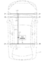
- FIG. 1 is a power supply system diagram of a vehicle 1 equipped with the in-vehicle power supply system according to the embodiment of the present disclosure.
- the vehicle 1 is a 5-door engine vehicle having four side doors and one back door.
- the vehicle 1 is connected to the first to sixth power supply hubs 11 to 16 and the first to sixth power supply hubs 11 to 16 which are electrically connected to the battery 2 via the main feeder line L1.
- the first to sixth ECUs 21 to 26 for controlling the on / off of the above, and the central control device 3 for controlling the first to sixth ECUs 21 to 26 are provided.
- the first to sixth ECUs 21 to 26 are electrically connected to the first to sixth power supply hubs 11 to 16 via an auxiliary feeder line L5 and a communication line L12 (shown in FIG. 3).
- the first to sixth ECUs 21 to 26 and the central control device 3 are examples of control devices. Further, the first to sixth ECUs 21 to 26 are examples of sub-control devices, while the central control device 3 is an example of a main control device.
- the vehicle 1 has a plurality of electronic devices D11 to D14, D21 to D25, and D31 to D33 that are operated by the electric power supplied from the battery 2.
- the electronic devices D11 to D14 are electronic devices (first electronic devices) capable of constantly supplying power from the battery 2, and can also be called constant power supply electronic devices.
- the electronic devices D21 to D25 and D31 to D33 are electronic devices (second electronic devices) capable of supplying electric power from the battery 2 by the operation of the occupant of the vehicle 1.
- the electronic devices D21 to D25 consume less power than the electronic devices D31 to D33, and can be called accessory electronic devices.
- the electronic devices D31 to D33 consume more power than the electronic devices D21 to D25, and can be called an ignition electronic device.
- the electronic devices D11 to D14 which can also be called constant power electronic devices, are, for example, the electronic device D11 is a keyless device, the electronic device D12 is a surveillance camera device for theft monitoring, the electronic device D13 is a burglar alarm device, and the electronic device D14 is a brake light. is there.
- the keyless device receives radio waves from the transmitter in the key held by the passenger.
- Electronic devices D21 to D25 which can also be called accessory electronic devices, are electronic devices that are supposed to be used regardless of whether the engine of the vehicle 1 is on or off.
- the electronic device D21 is a headlight
- the electronic device D22 is an electric mirror
- the electronic device D23 is an audio device
- the electronic device D24 is a rear camera device
- the electronic device D25 is a car navigation device.
- the display of the car navigation device displays an image taken by the rear camera device in response to the movement of the shift lever to the reverse position.
- the rear camera device is an example of a camera device.
- Electronic devices D31 to D33 which can also be called ignition electronic devices, can be used even when the engine of the vehicle 1 is off, but basically they are electronic devices that are supposed to be used when the engine is on.
- the electronic device D31 is an air conditioner
- the electronic device D32 is an electric power steering device
- the electronic device D33 is an electric power window.
- the electronic devices D11 to D14, D21 to D25, and D31 to D33 may include sensors, actuators, ECUs for controlling the actuators, and the like for operating the devices as described above.
- the vehicle 1 is divided into six zones, and any one of the first to sixth power supply hubs 11 to 16 is provided in each zone.
- the first power supply hub 11 is arranged in the left front zone.
- the second power supply hub 12 is arranged near the side door zone on the left front side.
- the third power hub 13 is arranged in the left rear zone.
- the fourth power supply hub 14 is arranged in the right front zone.
- the fifth power supply hub 15 is arranged near the side door zone on the right front side.
- the sixth power hub 16 is arranged in the right rear zone.
- a power supply path is formed from the battery 2 by the main feeder line L1 and the first to third power supply hubs 11 to 13 and the sub power supply lines L2 to L4, and from the battery 2 the main feeder line L1 and the fourth to sixth power supply hubs 14 to 16.
- a power supply path is formed by the auxiliary feeder lines L2 to L4.
- first to sixth power supply hubs 11 to 16 are arranged in the middle of the power supply path between the battery 2 and the electronic devices D11 to D14, D21 to D25, and D31 to D33. More specifically, the first power supply hub 11 is arranged in the middle of the power supply path between the electronic devices D12 and D21 in the left front zone and the battery 2.
- the second power hub 12 is provided between the electronic devices D11, D22, D33 and the battery 2 on the left side door zone or its vicinity, and in the middle of the power supply path between the electronic devices D25 and the battery 2 on the central side. Have been placed.
- the third power hub 13 is located between the electronic devices D14 and D23 in the left rear zone and the battery 2, between the electronic devices D14 and the battery 2 on the right rear side, and between the electronic devices D24 and the battery on the rear side. It is arranged in the middle of the power supply path between 2 and 2.
- the fourth power supply hub 14 is arranged in the middle of the power supply path between the electronic devices D12 and D21 in the right front zone and the battery 2.
- the fifth power supply hub 15 is arranged in the middle of the power supply path between the electronic devices D11, D22, D33 and the battery 2 in or near the side door zone on the right front side.
- the sixth power supply hub 16 is arranged in the middle of the power supply path between the electronic device D23 in the right rear zone and the battery 2.
- the 1st to 6th power supply hubs 11 to 16 are connected to the battery 2 or the nearby 1st to 6th power supply hubs 11 to 16 by a single main feeder line L1. More specifically, the first power supply hub 11 and the fourth power supply hub 14 are connected to the battery 2 by the main feeder line L1.
- the second power supply hub 12 is connected to the first power supply hub 11 by the main feeder line L1.
- the third power supply hub 13 is connected to the second power supply hub 12 by the main feeder line L1.
- the fifth power supply hub 15 is connected to the fourth power supply hub 14 by the main feeder line L1.
- the sixth power supply hub 16 is connected to the fifth power supply hub 15 by the main feeder line L1.
- Power is supplied to the first to sixth power supply hubs 11 to 16 via the main feeder line L1. More specifically, power is supplied from the battery 2 to each of the first and fourth power supply hubs 11 and 14 via the main feeder line L1. Power is supplied from the battery 2 to the second power supply hub 12 via the main feeder line L1 and the first power supply hub 11. Power is supplied from the battery 2 to the third power supply hub 13 via the main feeder line L1 and the first and second power supply hubs 11 and 12. Power is supplied from the battery 2 to the fourth power supply hub 14 via the main feeder line L1. Power is supplied from the battery 2 to the fifth power supply hub 15 via the main feeder line L1 and the fourth power supply hub 14. Power is supplied from the battery 2 to the sixth power supply hub 16 via the main feeder line L1 and the fourth and fifth power supply hubs 14 and 15.
- the 1st to 6th power supply hubs 11 to 16 are connected to the electronic devices D11 to D14, D21 to D25, and D31 to D33 via the auxiliary feeder lines L2 to L4. More specifically, the first and fourth power supply hubs 11 and 14, respectively, are connected to the electronic devices D12 and D21 via the auxiliary feeder lines L2 and L3, respectively.
- the second power supply hub 12 is connected to the electronic devices D11, D22, D25, D31, and D33 via the auxiliary feeder lines L2 to L4, respectively.
- the third power supply hub 13 is connected to the electronic devices D14, D23, and D24 via the auxiliary feeder lines L2 and L3.
- the fifth power supply hub 15 is connected to the electronic devices D11, D13, D22, D25, D32, and D33 via the auxiliary feeder lines L2 to L4, respectively.
- the sixth power supply hub 16 is connected to the electronic device D23 via the auxiliary feeder line L3.
- Each main feeder line L1 and each sub-feed line L2 to L4 may be any electric wire capable of supplying electric power, and is composed of, for example, a wire harness.
- the first power supply hub 11 is connected to the first ECU 21 via an auxiliary feeder line L5.
- the second power supply hub 12 is connected to the second ECU 22 via an auxiliary feeder line L5.
- the third power supply hub 13 is connected to the third ECU 23 via an auxiliary feeder line L5.
- the fourth power supply hub 14 is connected to the fourth ECU 24 via an auxiliary feeder line L5.
- the fifth power supply hub 15 is connected to the fifth ECU 25 via an auxiliary feeder line L5.
- the sixth power supply hub 16 is connected to the sixth ECU 26 via an auxiliary feeder line L5.
- the first to sixth ECUs 21 to 26 have a function of managing and controlling the electronic devices D11 to D14, D21 to D25, and D31 to D33.
- the 1st to 6th ECUs 21 to 26 receive detection results from various sensors (vehicle speed sensor, vehicle interior temperature sensor, etc.) and use them for processing in the own machine or transmit information to the central control device 3. To do.
- Each of the first to sixth ECUs 21 to 26 includes a microcomputer and a memory. In FIG. 3, which will be described later, the second ECU 22 is illustrated.
- Memory stores modules, which are software that can be executed by a microcomputer.
- the functions of the first to sixth ECUs 21 to 26 are realized, for example, by the microcomputer executing each module stored in the memory.
- some of the functions of the first to sixth ECUs 21 to 26 may be realized by a hardware circuit.
- the central control device 3 is composed of a microcomputer, an input / output circuit, a memory, and the like, and controls electronic devices D11 to D14, D21 to D25, and D31 to D33.
- Memory stores modules, which are software that can be executed by a microcomputer.
- the function of the central processing unit 3 is realized, for example, by the microcomputer executing each module stored in the memory.
- There may be a plurality of microcomputers and a plurality of memories, respectively. Further, a part of the functions of the central processing unit 3 may be realized by a hardware circuit.
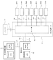
- FIG. 2 is a signal system diagram of a main part of the vehicle 1.
- the first to sixth ECUs 21 to 26 are configured to input control signals from the central control device 3 that controls the entire control of the vehicle 1. More specifically, the central control device 3 and the first to sixth ECUs 21 to 26 are connected to each other by the communication wiring L11. As a result, the control signal output from the central control device 3 is input to the first to sixth ECUs 21 to 26 via the communication wiring L11. At this time, the first to sixth ECUs 21 to 26 supply electric power to the electronic devices D11 to D14, D21 to D25, and D31 to D33 based on the control signal from the central control device 3, or cut off the electric power. To do.
- CAN Controller Area Network
- CAN-FD CAN with Flexible Data rate
- a communication method may be used, or a plurality of communication methods may be used in combination.
- FIG. 3 is a diagram showing the power supply topology of the zone in which the second power supply hub 12 is arranged (the side door zone on the left front side of the vehicle 1).
- L12 is a communication line connecting the second power supply hub 12 and the second ECU 22.
- the second power supply hub 12 has a relay unit 50 that turns on / off the energization of the electronic devices D11, D22, D25, D31, and D33.
- the electronic device D11 is a keyless device
- the electronic device D22 is an electric mirror
- the electronic device D25 is a car navigation device
- the electronic device D31 is an air conditioner
- the electronic device D33 is an electric power window.
- the relay unit 50 is electrically connected to the battery 2 via the main feeder line L1.
- the relay unit 50 is electrically connected to the electronic devices D11, D22, D25, D31, and D33 via the auxiliary feeder lines L2, L3, and L4.
- the relay unit 50 includes a plurality of relays (not shown) for individually turning on / off the energization of the electronic devices D11, D22, D25, D31, and D33. Each of the relays is turned on and off according to the input of the control signal from the central control device 3.
- the relay of the relay unit 50 is composed of a so-called mechanical relay or a semiconductor relay. By cutting off the relay of the relay unit 50, it is possible to cut off all energization of the electronic devices D11, D22, D25, D31, and D33, so that the generation of so-called dark current can be eliminated.
- the first, third to sixth power supply hubs 11, 13 to 16 are also configured in the same manner as the second power supply hub 12.
- the central control device 3 has a predetermined allowable current consumption (mA order) according to the usage scene of the vehicle 1 based on the conditions relating to the current consumption of the plurality of electronic devices D11 to D14, D21 to D25, and D31 to D33.
- the power supply to the plurality of electronic devices D11 to D14, D21 to D25, and D31 to D33 is controlled so as to be less than.
- the conditions related to the current consumption of the plurality of electronic devices D11 to D14, D21 to D25, and D31 to D33 are stored in advance in the central control device 3, but the central control device 3 is a server on the external network via the in-vehicle communication device. It may be configured to acquire the conditions according to the situation in which the vehicle is placed by referring to. In the latter case, the current consumption can be minimized even in the case of an unexpected vehicle condition such as a disaster that prevents refueling or charging for the time being.
- the energizing time for demonstrating the functions of the plurality of electronic devices D11 to D14, D21 to D25, D31 to D33 and the plurality of electronic devices D11 to D14, D21 to D25, D31 to D33 The allowable current consumption is determined according to the usage scene of the vehicle 1 based on the current consumption of the above and the standby currents of the plurality of electronic devices D11 to D14, D21 to D25, and D31 to D33.
- the current consumption becomes less than the allowable current consumption determined in advance according to the usage scene of the vehicle 1 based on the conditions regarding the current consumption of the plurality of electronic devices D11 to D14, D21 to D25, and D31 to D33.
- the usage scene of the vehicle 1 is obtained by controlling the first to sixth ECUs 21 to 26 by the central control device 3 to turn on / off the power supply to the plurality of electronic devices D11 to D14, D21 to D25, and D31 to D33.
- the power supply to each of the electronic devices D11 to D14, D21 to D25, and D31 to D33 is minimized accordingly. As a result, the early rise of the battery 2 can be suppressed.
- the power supply may be turned off depending on the usage scene of the vehicle 1.
- the usage scenes of the vehicle 1 include a scene of updating the program of the central control device 3, a scene from factory shipment to the end of transportation (including the inside of a transport ship), a scene of parking not used by the user, and the like. is there.
- Information on the usage scene of the vehicle 1 is input to the central control device 3 by an operating means such as a wired communication (or wireless communication) with an external terminal or a switch.
- priority is given to supplying power to the necessary electronic devices among the electronic devices D11 to D14, D21 to D25, and D31 to D33, and the electronic devices D11 to D14 and D21 are given priority.
- the power supply to D25 and D31 to D33 can be minimized.
- the vehicle equipped with the in-vehicle power supply system estimates the passenger's intention to use an electronic device based on the behavior of the passenger and the condition of the vehicle, and the passenger starts energizing the electronic device. It is optimized so that it can be provided at the desired timing such as information provision from the above, and the current is not wasted by energizing quickly.
- the back camera when the back camera is activated, when the vehicle is traveling at a low speed in the parking lot or near the parking space, when the foot brake is stepped on (vehicle condition), the occupant uses the indoor camera with one hand on the shift lever. When it recognizes that it is extended (passenger status), it starts energizing the back camera.
- the energization itself is physically cut off by the relay of the relay unit 50, and the power supply itself is physically cut off by the relay of the relay unit 50, and the predetermined time before the required time. Since energization is started, so-called dark current can be eliminated at all.
- control load of the central control device 3 can be reduced by controlling the on / off of energization of the electronic devices D11 to D14, D21 to D25, and D31 to D33 by the first to sixth ECUs 21 to 26. ..
- the in-vehicle power supply system of the above embodiment is configured so that the vehicle 1 is divided into six zones and the on / off of the power supply of the electronic devices D11 to D14, D21 to D25, and D31 to D33 can be controlled for each zone.
- the division and number of zones are not limited to this.
- the vehicle 1 is an engine vehicle, but may be, for example, a plug-in hybrid vehicle, an electric vehicle, or the like.
- the electronic device D has been described in the case where the power is supplied from the battery 2, but when the engine is on, the power is supplied from the alternator (not shown).
- the third power supply hub 13 and the sixth power supply hub 16 are not directly electrically connected by the main feeder line L1, but the main feeder line L1 may be provided. In other words, the third power supply hub 13 may be electrically connected to the sixth power supply hub 16 via the main feeder line L1.
- the first to sixth power supply hubs 11 to 16 are provided separately from the first to sixth ECUs 21 to 26, but they may be provided integrally with the first to sixth ECUs 21 to 26. Good. In other words, at least one of the first to sixth power supply hubs 11 to 16 may be configured to have the same function as the first to sixth ECUs 21 to 26.
Landscapes
- Engineering & Computer Science (AREA)
- Mechanical Engineering (AREA)
- Power Engineering (AREA)
- Physics & Mathematics (AREA)
- General Physics & Mathematics (AREA)
- Automation & Control Theory (AREA)
- Charge And Discharge Circuits For Batteries Or The Like (AREA)
- Direct Current Feeding And Distribution (AREA)
Abstract
車載電源システムは、主給電線(L1)に接続された第1~第6電源ハブ(11~16)と、第1~第6電源ハブ(11~16)に副給電線(L2~L4)を介して接続された電子機器(D11~D14,D21~D25,D31~D33)と、電子機器(D11~D14,D21~D25,D31~D33)への給電を制御する制御装置(第1~第6ECU21~26および中央制御装置3)とを備える。制御装置は、電子機器(D11~D14,D21~D25,D31~D33)の消費電流に関する条件に基づいて、車両の使用シーンに応じて予め定められた許容消費電流未満になるように、電子機器(D11~D14,D21~D25,D31~D33)への給電を制御する。
Description
本開示は、車載電源システムに関する。
従来、車載電源システムとしては、車両内に多数の電子機器が配置され、各電子機器に給電線を介して電源が供給される構成のものがある(例えば、特開2016-201740号公報(特許文献1)参照)。
上記車載電源システムでは、電源からの給電線の構成について特に考慮されておらず、電子機器が増大した場合、車両の使用シーンに応じて各電子機器への給電を最小限にして消費電力を抑制するということができない。
本開示は、車両の使用シーンに応じて各電子機器への給電を最小限に抑える車載電源システムを提供する。
本開示の車載電源システムは、
主給電線に接続された複数の電源ハブと、
上記複数の電源ハブに副給電線を介して接続された複数の電子機器と、
上記複数の電子機器への給電を制御する制御装置と
を備え、
上記複数の電源ハブは、それぞれ1つの上記主給電線により他の電源ハブと接続されており、
上記制御装置は、上記複数の電子機器の消費電流に関する条件に基づいて、車両の使用シーンに応じて予め定められた許容消費電流未満になるように、上記複数の電子機器への給電を制御することを特徴とする。
主給電線に接続された複数の電源ハブと、
上記複数の電源ハブに副給電線を介して接続された複数の電子機器と、
上記複数の電子機器への給電を制御する制御装置と
を備え、
上記複数の電源ハブは、それぞれ1つの上記主給電線により他の電源ハブと接続されており、
上記制御装置は、上記複数の電子機器の消費電流に関する条件に基づいて、車両の使用シーンに応じて予め定められた許容消費電流未満になるように、上記複数の電子機器への給電を制御することを特徴とする。
上記構成によれば、複数の電子機器の消費電流に関する条件に基づいて、車両の使用シーンに応じて予め定められた許容消費電流未満になるように、制御装置により複数の電子機器への給電を制御することによって、車両の使用シーンに応じて各電子機器への給電を最小限に抑えることができる。
また、本開示の一態様に係る車載電源システムでは、
上記複数の電子機器の消費電流に関する条件は、上記複数の電子機器の機能を発揮する通電時間と、上記複数の電子機器の消費電流と、上記複数の電子機器の待機電流である。
上記複数の電子機器の消費電流に関する条件は、上記複数の電子機器の機能を発揮する通電時間と、上記複数の電子機器の消費電流と、上記複数の電子機器の待機電流である。
上記構成によれば、電子機器毎の機能を発揮する通電時間,消費電力,待機電流に基づいて、車両の使用シーンに応じた許容消費電流を決定することで、バッテリの早期上がりを効果的に抑制できる。
また、本開示の一態様に係る車載電源システムでは、
上記車両の使用シーンは、上記制御装置のプログラムを更新するシーンを含む。
上記車両の使用シーンは、上記制御装置のプログラムを更新するシーンを含む。
上記構成によれば、制御装置のプログラムを更新するシーンにおいて必要な電子機器への給電を優先して、各電子機器への給電を必要最小限できる。
また、本開示の一態様に係る車載電源システムでは、
上記車両の使用シーンは、工場出荷から輸送が終了するまでのシーンを含む。
上記車両の使用シーンは、工場出荷から輸送が終了するまでのシーンを含む。
上記構成によれば、工場出荷から輸送が終了するまでのシーンにおいて必要な電子機器への給電を優先して、各電子機器への給電を必要最小限できる。
また、本開示の一態様に係る車載電源システムでは、
上記車両の使用シーンは、ユーザーが使用しない駐車中のシーンを含む。
上記車両の使用シーンは、ユーザーが使用しない駐車中のシーンを含む。
上記構成によれば、ユーザーが使用しない駐車中のシーンにおいて必要な電子機器への給電を優先して、各電子機器への給電を必要最小限できる。
以上より明らかなように、この本開示によれば、車両の使用シーンに応じて各電子機器への給電を最小限に抑える車載電源システムを実現できる。
以下、この本開示の車載電源システムを図示の実施の形態により詳細に説明する。なお、図面において、同一の参照番号は、同一部分または相当部分を表わすものである。また、以下の説明において、「前」、「後」、「右」および「左」とは、「車両1の前」、「車両1の後」、「車両1の右」および「車両1の左」を意味する。例えば、「前後方向」は、「車両1の前後方向」を指す。
図1は、本開示の実施形態の車載電源システムが搭載された車両1の電源系統図である。この車両1は、4つのサイドドアと1つのバックドアとを備える5ドア式のエンジン自動車である。
車両1は、図1に示すように、バッテリ2に主給電線L1を介して電気的に接続される第1~第6電源ハブ11~16と、第1~第6電源ハブ11~16に副給電線L2~L5を介して電気的に接続される複数の電子機器D11~D14,D21~D25,D31~D33と、複数の電子機器D11~D14,D21~D25,D31~D33への通電のオン・オフを制御する第1~第6ECU21~26と、第1~第6ECU21~26を制御する中央制御装置3とを備える。この第1~第6ECU21~26は、副給電線L5および通信線L12(図3に示す)を介して第1~第6電源ハブ11~16に電気的に接続される。
なお、第1~第6ECU21~26および中央制御装置3は、制御装置の一例である。また、第1~第6ECU21~26は副制御装置の一例である一方、中央制御装置3は主制御装置の一例である。
より詳しく説明すると、車両1は、バッテリ2から供給される電力により作動する複数の電子機器D11~D14,D21~D25,D31~D33を有する。電子機器D11~D14は、常時、バッテリ2から電力供給が可能な電子機器(第1の電子機器)であって、常時電源電子機器とも呼べる。一方、電子機器D21~D25,D31~D33は、車両1の乗員の操作によりバッテリ2からの電力供給が可能になる電子機器(第2の電子機器)である。また、電子機器D21~D25は、電子機器D31~D33に比べて、電力消費が小さく、アクセサリ電子機器とも呼べる。また、電子機器D31~D33は、電子機器D21~D25に比べて、電力消費が大きく、イグニッション電子機器とも呼べる。
常時電源電子機器とも呼べる電子機器D11~D14は、例えば、電子機器D11はキーレス装置、電子機器D12は盗難監視用の監視カメラ装置、電子機器D13はバーグラアラーム装置、電子機器D14はブレーキ灯である。上記キーレス装置は、搭乗者が持つキー内の送信機からの電波を受信する。
アクセサリ電子機器とも呼べる電子機器D21~D25は、車両1のエンジンのオン・オフに関わらずに使用することを想定された電子機器である。例えば、電子機器D21は前照灯で、電子機器D22は電動ミラーで、電子機器D23はオーディオ機器で、電子機器D24はリヤカメラ装置、電子機器D25はカーナビゲーション装置である。上記カーナビゲーション装置のディスプレイは、シフトレバーのリバース位置への移動に応じて、上記リヤカメラ装置が撮影した映像を表示する。なお、上記リヤカメラ装置はカメラ装置の一例である。
イグニッション電子機器とも呼べる電子機器D31~D33は、車両1のエンジンがオフの状態でも使用可能であるが、基本的にはエンジンがオンの時に使用することを想定された電子機器である。例えば、電子機器D31は空調装置で、電子機器D32は電動パワーステアリング装置で、電子機器D33は電動パワーウィンドウである。
電子機器D11~D14,D21~D25,D31~D33は、上述したような装置を作動させるためのセンサ、アクチュエータ、アクチュエータを制御するECUなどを含んでもよい。
上記車両1の電源系統では、車両1を6つのゾーンに分けて、各ゾーンに第1~第6電源ハブ11~16のいずれか一つが設けられている。第1電源ハブ11は左前側ゾーンに配置されている。第2電源ハブ12は左前側のサイドドアゾーン近傍に配置されている。第3電源ハブ13は左後側ゾーンに配置されている。第4電源ハブ14は右前側ゾーンに配置されている。第5電源ハブ15は右前側のサイドドアゾーン近傍に配置されている。第6電源ハブ16は右後側ゾーンに配置されている。なお、上記ゾーンの数を増減させる場合、第1~第6電源ハブ11~16の個数はゾーンの数の増減に応じて増減する。
バッテリ2から主給電線L1と第1~第3電源ハブ11~13および副給電線L2~L4で電源経路が形成され、バッテリ2から主給電線L1と第4~第6電源ハブ14~16および副給電線L2~L4で電源経路が形成されている。なお、図示していないが、電源経路には、通電容量に応じたヒューズが必要に応じて配設されている。
また、第1~第6電源ハブ11~16は、バッテリ2と電子機器D11~D14,D21~D25,D31~D33との間における電源経路の途中に配置されている。より具体的に言うと、第1電源ハブ11は、左前側ゾーンの電子機器D12,D21とバッテリ2との間における電源経路の途中に配置されている。第2電源ハブ12は、左側のサイドドアゾーンまたはその近傍の電子機器D11,D22,D33とバッテリ2との間、かつ、中央側の電子機器D25とバッテリ2との間における電源経路の途中に配置されている。第3電源ハブ13は、左後側ゾーンの電子機器D14,D23とバッテリ2との間、かつ、右後側の電子機器D14とバッテリ2との間、かつ、後側の電子機器D24とバッテリ2との間における電源経路の途中に配置されている。第4電源ハブ14は、右前側ゾーンの電子機器D12,D21とバッテリ2との間における電源経路の途中に配置されている。第5電源ハブ15は、右前側のサイドドアゾーンまたはその近傍の電子機器D11,D22,D33とバッテリ2との間における電源経路の途中に配置されている。また、第6電源ハブ16は、右後側ゾーンの電子機器D23とバッテリ2との間における電源経路の途中に配置されている。
また、第1~第6電源ハブ11~16は、バッテリ2または近傍の第1~第6電源ハブ11~16と単独の主給電線L1によりそれぞれ接続されている。より具体的に言うと、第1電源ハブ11および第4電源ハブ14は、主給電線L1によりバッテリ2と接続されている。第2電源ハブ12は、主給電線L1により第1電源ハブ11と接続されている。第3電源ハブ13は、主給電線L1により第2電源ハブ12と接続されている。第5電源ハブ15は、主給電線L1により第4電源ハブ14と接続されている。第6電源ハブ16は、主給電線L1により第5電源ハブ15と接続されている。
第1~第6電源ハブ11~16は、主給電線L1を介して電力が供給される。より具体的に言うと、第1,第4電源ハブ11,14のそれぞれには、バッテリ2から主給電線L1を経由した電力が供給される。第2電源ハブ12には、バッテリ2から主給電線L1および第1電源ハブ11を経由した電力が供給される。第3電源ハブ13には、バッテリ2から主給電線L1および第1,第2電源ハブ11,12を経由した電力が供給される。第4電源ハブ14には、バッテリ2から主給電線L1を経由した電力が供給される。第5電源ハブ15には、バッテリ2から主給電線L1および第4電源ハブ14を経由した電力が供給される。第6電源ハブ16には、バッテリ2から主給電線L1および第4,第5電源ハブ14,15を経由した電力が供給される。
また、第1~第6電源ハブ11~16は、副給電線L2~L4を介して電子機器D11~D14,D21~D25,D31~D33と接続されている。より具体的に言うと、第1,第4電源ハブ11,14は、それぞれ、副給電線L2,L3を介して電子機器D12,D21と接続されている。第2電源ハブ12は、それぞれ、副給電線L2~L4を介して電子機器D11,D22,D25,D31,D33と接続されている。第3電源ハブ13は、副給電線L2,L3を介して電子機器D14,D23,D24と接続されている。第5電源ハブ15は、それぞれ、副給電線L2~L4を介して電子機器D11,D13,D22,D25,D32,D33と接続されている。第6電源ハブ16は、副給電線L3を介して電子機器D23と接続されている。
各主給電線L1および各副給電線L2~L4は、電力が供給できる電線であればよく、例えばワイヤーハーネスで構成されている。
第1電源ハブ11は副給電線L5を介して第1ECU21と接続されている。第2電源ハブ12は副給電線L5を介して第2ECU22と接続されている。第3電源ハブ13は副給電線L5を介して第3ECU23と接続されている。第4電源ハブ14は副給電線L5を介して第4ECU24と接続されている。第5電源ハブ15は副給電線L5を介して第5ECU25と接続されている。第6電源ハブ16は副給電線L5を介して第6ECU26と接続されている。
第1~第6ECU21~26は、各電子機器D11~D14,D21~D25,D31~D33を管理および制御する機能を有する。例えば、第1~第6ECU21~26は、各種センサ(車速センサや車室内温度センサ等)からの検出結果を受信して、自機内での処理に使用したり、中央制御装置3に情報を送信したりする。
第1~第6ECU21~26は、それぞれ、マイクロコンピュータとメモリとを備える。後述する図3では、第2ECU22について図示している。メモリは、マイクロコンピュータによって実行可能なソフトウェアであるモジュールを格納している。第1~第6ECU21~26の機能は、例えば、マイクロコンピュータが、メモリに格納された各モジュールを実行することによって実現される。なお、マイクロコンピュータ及びメモリは、それぞれ、複数個あってもかまわない。また、第1~第6ECU21~26の機能の一部が、ハードウェア回路で実現されていてもよい。
中央制御装置3は、マイクロコンピュータ、入出力回路、メモリなどから構成されて、電子機器D11~D14,D21~D25,D31~D33を制御する。メモリは、マイクロコンピュータによって実行可能なソフトウェアであるモジュールを格納している。中央演算装置3の機能は、例えば、マイクロコンピュータが、メモリに格納された各モジュールを実行することによって実現される。なお、マイクロコンピュータ及びメモリは、それぞれ、複数個あってもかまわない。また、中央演算装置3の機能の一部が、ハードウェア回路で実現されていてもよい。
図2は、車両1の要部の信号系統図である。
第1~第6ECU21~26は、図2に示すように、車両1の全体の制御を統括する中央制御装置3からの制御信号がそれぞれ入力されるように構成されている。より具体的に言うと、中央制御装置3と第1~第6ECU21~26とは、通信配線L11により、互いに接続されている。これにより、中央制御装置3から出力された制御信号は、通信配線L11を介して第1~第6ECU21~26に入力される。このとき、第1~第6ECU21~26は、中央制御装置3からの制御信号に基づいて、電子機器D11~D14,D21~D25,D31~D33へ電力を供給したり、その電力を遮断したりする。
中央制御装置3と第1~第6ECU21~26との間の通信方式(通信プロトコル)は、例えばCAN(Controller Area Network)やCAN-FD(CAN with Flexible Data rate)を用いているが、他の通信方式でもよいし、複数の通信方式を組み合わせて用いてもよい。
図3は、第2電源ハブ12が配置されたゾーン(車両1の左前側のサイドドアゾーン)の電源トポロジーを示す図である。図3において、L12は第2電源ハブ12と第2ECU22とを接続する通信線である。
図3に示すように、第2電源ハブ12は、電子機器D11,D22,D25,D31,D33への通電をオン・オフするリレー部50を有する。例えば、電子機器D11はキーレス装置、電子機器D22は電動ミラー、電子機器D25はカーナビゲーション装置、電子機器D31は空調装置、電子機器D33は電動パワーウィンドウである。リレー部50は、主給電線L1を介してバッテリ2と電気的に接続されている。リレー部50は、副給電線L2,L3,L4を介して電子機器D11,D22,D25,D31,D33と電気的に接続されている。リレー部50は、電子機器D11,D22,D25,D31,D33への通電を個別にオン・オフするための複数のリレー(図示せず)を含んでいる。この各リレーは、中央制御装置3からの制御信号の入力に応じてオン・オフする。リレー部50のリレーは、いわゆるメカリレーまたは半導体リレーで構成される。リレー部50のリレーの遮断により当該電子機器D11,D22,D25,D31,D33に対する一切の通電を遮断できるため、いわゆる暗電流の発生を撲滅できる。
なお、第1,第3~第6電源ハブ11,13~16も、第2電源ハブ12と同様に構成されている。
上記中央制御装置3は、複数の電子機器D11~D14,D21~D25,D31~D33の消費電流に関する条件に基づいて、車両1の使用シーンに応じて予め定められた許容消費電流(mAオーダー)未満になるように、複数の電子機器D11~D14,D21~D25,D31~D33への給電を制御する。
複数の電子機器D11~D14,D21~D25,D31~D33の消費電流に関する条件は、中央制御装置3に予め記憶されているが、中央制御装置3が車載通信装置を介して外部ネットワーク上のサーバーを参照し、その車両が置かれた状況に応じた条件を取得する構成としてもよい。後者の場合、例えば災害が発生し給油や充電が当面受けられなくなる等の想定外の車両状況が生じた場合であっても、電流消費を最小化できる。
また、この実施形態の車載電源システムでは、複数の電子機器D11~D14,D21~D25,D31~D33の機能を発揮する通電時間と、複数の電子機器D11~D14,D21~D25,D31~D33の消費電流と、複数の電子機器D11~D14,D21~D25,D31~D33の待機電流に基づいて、車両1の使用シーンに応じて許容消費電流を決定している。
上記構成の車載電源システムでは、複数の電子機器D11~D14,D21~D25,D31~D33の消費電流に関する条件に基づいて、車両1の使用シーンに応じて予め定められた許容消費電流未満になるように、中央制御装置3により第1~第6ECU21~26を制御して複数の電子機器D11~D14,D21~D25,D31~D33への給電をオン・オフすることによって、車両1の使用シーンに応じて各電子機器D11~D14,D21~D25,D31~D33への給電を最小限に抑えるようにしている。これにより、バッテリ2の早期上がりを抑制できる。
この場合は、アクセサリ電子機器とも呼べる電子機器D21~D25であっても、車両1の使用シーンによっては給電をオフする場合がある。
また、電子機器D11~D14,D21~D25,D31~D33毎の機能を発揮する通電時間,消費電力,待機電流に基づいて、車両1の使用シーンに応じた許容消費電流を決定することで、バッテリ2の早期上がりを効果的に抑制できる。
ここで、車両1の使用シーンとしては、中央制御装置3のプログラムを更新するシーン、工場出荷から輸送が終了するまでのシーン(運搬船内などを含む)、ユーザーが使用しない駐車中のシーンなどがある。なお、車両1の使用シーンの情報は、外部端末との有線通信(または無線通信)やスイッチなどの操作手段により中央制御装置3に入力される。
例えば、中央制御装置3のプログラムを更新するシーンにおいて、電子機器D11~D14,D21~D25,D31~D33のうちの必要な電子機器への給電を優先して、各電子機器D11~D14,D21~D25,D31~D33への給電を必要最小限できる。
また、工場出荷から輸送が終了するまでのシーンにおいて子機器D11~D14,D21~D25,D31~D33のうちの必要な電子機器への給電を優先して、各電子機器D11~D14,D21~D25,D31~D33への給電を必要最小限できる。
また、ユーザーが使用しない駐車中のシーンにおいて、電子機器D11~D14,D21~D25,D31~D33のうちの必要な電子機器への給電を優先して、各電子機器D11~D14,D21~D25,D31~D33への給電を必要最小限できる。
上記車載電源システムを備えた車両が、搭乗者の行動と車両の状況に基づいて搭乗者がある電子機器を使用する意思を推定し、当該電子機器への通電開始を、搭乗者が当該電子機器からの情報提供等を望むタイミングでこれを提供でき、かつ早く通電して無駄に電流を消費することがないよう、最適化する。
例えば、バックカメラの起動であれば、車両が駐車場内または駐車スペース近傍において低車速で走行しているところ、フットブレーキを踏んだとき(車両の状況)、さらに室内カメラで乗員がシフトレバーに片手を伸ばすのを認識(搭乗者の状況)場合に、バックカメラに通電を開始する。
また、上記車載電源システムでは、電子機器に最小限の給電をして待機させておくのではなく、通電自体をリレー部50のリレーにより物理的に遮断しておき、必要時点の所定時間前に通電を開始するため、いわゆる暗電流を一切生じなくすることができる。
また、第1~第6ECU21~26によって、電子機器D11~D14,D21~D25,D31~D33への通電のオン・オフを制御することで、中央制御装置3の制御負荷を低減することができる。
上記実施形態の車載電源システムは、車両1を6つのゾーンに分けると共に、ゾーン毎に電子機器D11~D14,D21~D25,D31~D33の電力供給のオン・オフが制御できるように構成されていたが、ゾーンの分け方や数はこれに限らない。
上記実施形態では、車両1は、エンジン自動車であったが、例えば、プラグインハイブリッド自動車や電気自動車等であってもよい。
上記実施形態では、電子機器Dは、バッテリ2から電源が供給される場合について説明したが、エンジンがオンのときはオルタネータ(図示せず)から電源が供給される。
上記実施形態では、第3電源ハブ13と第6電源ハブ16との間を主給電線L1で電気的に直接接続していなかったが、主給電線L1を設けられるようにしてもよい。別の言い方をすれば、第3電源ハブ13は、主給電線L1を介して第6電源ハブ16に電気的に接続されるようにしてもよい。
上記実施形態では、第1~第6電源ハブ11~16は、第1~第6ECU21~26と別体で設けられていたが、第1~第6ECU21~26と一体に設けられるようにしてもよい。別の言い方をすれば、第1~第6電源ハブ11~16の少なくとも1つは、第1~第6ECU21~26と同様の機能を有するにように構成されてもよい。
本開示の具体的な実施の形態について説明したが、本開示は上記実施形態に限定されるものではなく、本開示の範囲内で種々変更して実施することができる。例えば、上記実施形態で記載した内容を適宜組み合わせたものを、本開示の一実施形態としてもよい。
1 車両
2 バッテリ
3 中央制御装置(制御装置)
11 第1電源ハブ
12 第2電源ハブ
13 第3電源ハブ
14 第4電源ハブ
15 第5電源ハブ
16 第6電源ハブ
21 第1ECU(制御装置)
22 第2ECU(制御装置)
23 第3ECU(制御装置)
24 第4ECU(制御装置)
25 第5ECU(制御装置)
26 第6ECU(制御装置)
50 リレー部
D11~D14,D21~D25,D31~D33 電子機器
L1 主給電線
L2~L4 副給電線
L11 通信線
L12 通信線
2 バッテリ
3 中央制御装置(制御装置)
11 第1電源ハブ
12 第2電源ハブ
13 第3電源ハブ
14 第4電源ハブ
15 第5電源ハブ
16 第6電源ハブ
21 第1ECU(制御装置)
22 第2ECU(制御装置)
23 第3ECU(制御装置)
24 第4ECU(制御装置)
25 第5ECU(制御装置)
26 第6ECU(制御装置)
50 リレー部
D11~D14,D21~D25,D31~D33 電子機器
L1 主給電線
L2~L4 副給電線
L11 通信線
L12 通信線
Claims (5)
- 主給電線に接続された複数の電源ハブと、
上記複数の電源ハブに副給電線を介して接続された複数の電子機器と、
上記複数の電子機器への給電を制御する制御装置と
を備え、
上記複数の電源ハブは、それぞれ1つの上記主給電線により他の電源ハブと接続されており、
上記制御装置は、上記複数の電子機器の消費電流に関する条件に基づいて、車両の使用シーンに応じて予め定められた許容消費電流未満になるように、上記複数の電子機器への給電を制御することを特徴とする車載電源システム。 - 請求項1に記載の車載電源システムにおいて、
上記複数の電子機器の消費電流に関する条件は、上記複数の電子機器の機能を発揮する通電時間と、上記複数の電子機器の消費電流と、上記複数の電子機器の待機電流であることを特徴とする車載電源システム。 - 請求項1または2に記載の車載電源システムにおいて、
上記車両の使用シーンは、上記制御装置のプログラムを更新するシーンを含むことを特徴とする車載電源システム。 - 請求項1から3までのいずれか1つに記載の車載電源システムにおいて、
上記車両の使用シーンは、工場出荷から輸送が終了するまでのシーンを含むことを特徴とする車載電源システム。 - 請求項1から4までのいずれか1つに記載の車載電源システムにおいて、
上記車両の使用シーンは、ユーザーが使用しない駐車中のシーンを含むことを特徴とする車載電源システム。
Priority Applications (3)
| Application Number | Priority Date | Filing Date | Title |
|---|---|---|---|
| CN202080054331.7A CN114174944A (zh) | 2019-07-30 | 2020-07-22 | 车载电源系统 |
| EP20848210.9A EP4001018B1 (en) | 2019-07-30 | 2020-07-22 | In-vehicle power supply system |
| US17/630,937 US11970121B2 (en) | 2019-07-30 | 2020-07-22 | In-vehicle power supply system |
Applications Claiming Priority (2)
| Application Number | Priority Date | Filing Date | Title |
|---|---|---|---|
| JP2019139373A JP2021020606A (ja) | 2019-07-30 | 2019-07-30 | 車載電源システム |
| JP2019-139373 | 2019-07-30 |
Publications (1)
| Publication Number | Publication Date |
|---|---|
| WO2021020257A1 true WO2021020257A1 (ja) | 2021-02-04 |
Family
ID=74230301
Family Applications (1)
| Application Number | Title | Priority Date | Filing Date |
|---|---|---|---|
| PCT/JP2020/028368 Ceased WO2021020257A1 (ja) | 2019-07-30 | 2020-07-22 | 車載電源システム |
Country Status (5)
| Country | Link |
|---|---|
| US (1) | US11970121B2 (ja) |
| EP (1) | EP4001018B1 (ja) |
| JP (1) | JP2021020606A (ja) |
| CN (1) | CN114174944A (ja) |
| WO (1) | WO2021020257A1 (ja) |
Families Citing this family (4)
| Publication number | Priority date | Publication date | Assignee | Title |
|---|---|---|---|---|
| JP7904726B2 (ja) * | 2022-05-27 | 2026-08-13 | Astemo株式会社 | 車載制御装置 |
| JP7765639B2 (ja) * | 2022-07-25 | 2025-11-06 | Astemo株式会社 | 車載制御装置 |
| CN115402329A (zh) * | 2022-08-30 | 2022-11-29 | 重庆长安汽车股份有限公司 | 一种车辆耗能管理方法、装置、设备及介质 |
| CN116811766A (zh) * | 2023-06-19 | 2023-09-29 | 长城汽车股份有限公司 | 车辆的供电控制方法、装置、计算机存储介质及车辆 |
Citations (5)
| Publication number | Priority date | Publication date | Assignee | Title |
|---|---|---|---|---|
| JP2002539652A (ja) * | 1999-02-04 | 2002-11-19 | エリクソン インコーポレイテッド | 自動車イグニションを改善した通信アクセサリ |
| JP2009149243A (ja) * | 2007-12-21 | 2009-07-09 | Denso Corp | 車両制御装置およびそれを用いた車両制御システム |
| JP2009278531A (ja) * | 2008-05-16 | 2009-11-26 | Autonetworks Technologies Ltd | 回路装置 |
| JP2016201740A (ja) | 2015-04-13 | 2016-12-01 | 株式会社デンソー | 車載通信システム、中継装置及びノード |
| JP2019102305A (ja) * | 2017-12-04 | 2019-06-24 | 矢崎総業株式会社 | 車両用の回路体 |
Family Cites Families (13)
| Publication number | Priority date | Publication date | Assignee | Title |
|---|---|---|---|---|
| JP3338328B2 (ja) | 1997-04-21 | 2002-10-28 | 株式会社日立製作所 | 乗物の電力供給装置 |
| US9379559B2 (en) * | 2012-02-03 | 2016-06-28 | International Business Machines Corporation | System and method of charging a vehicle using a dynamic power grid, and system and method of managing power consumption in the vehicle |
| JP5496303B2 (ja) * | 2012-10-11 | 2014-05-21 | 三菱電機株式会社 | 車両制御システムおよび車両制御方法 |
| CN103770775A (zh) * | 2012-10-23 | 2014-05-07 | 广州汽车集团股份有限公司 | 一种混合动力车辆的设备保护装置及其工作方法 |
| CN202923541U (zh) * | 2012-10-23 | 2013-05-08 | 广州汽车集团股份有限公司 | 一种混合动力车辆的设备保护装置 |
| US8938332B1 (en) * | 2013-09-11 | 2015-01-20 | Cisco Technology, Inc. | Startup control of devices |
| JP5712308B1 (ja) * | 2014-01-29 | 2015-05-07 | 株式会社テック | 車両用エネルギー消費率改善装置、および車両用エネルギー消費率改善方法 |
| CN105313801B (zh) * | 2014-05-30 | 2018-01-16 | 矢崎总业株式会社 | 车用线束构造和追加连接部件 |
| JP6353746B2 (ja) * | 2014-08-26 | 2018-07-04 | 矢崎総業株式会社 | 車両用電源制御システム、ワイヤハーネス及び車両用電源制御装置 |
| JP6387040B2 (ja) | 2016-04-28 | 2018-09-05 | 矢崎総業株式会社 | 車両電源制御装置 |
| DE112017003145B4 (de) * | 2016-06-24 | 2023-02-16 | Yazaki Corporation | Fahrzeugstromkreiskörper |
| DE102018210844A1 (de) * | 2018-07-02 | 2020-01-02 | Robert Bosch Gmbh | Vorrichtung zum Ansteuern eines elektrischen Verbrauchers in einem Fahrzeug-Bordnetz und Bordnetz eines Fahrzeugs |
| US11590933B2 (en) * | 2020-09-03 | 2023-02-28 | Toyota Motor Engineering & Manufacturing North America, Inc. | Methods and systems for controlling operating conditions of vehicle components |
-
2019
- 2019-07-30 JP JP2019139373A patent/JP2021020606A/ja active Pending
-
2020
- 2020-07-22 US US17/630,937 patent/US11970121B2/en active Active
- 2020-07-22 WO PCT/JP2020/028368 patent/WO2021020257A1/ja not_active Ceased
- 2020-07-22 CN CN202080054331.7A patent/CN114174944A/zh active Pending
- 2020-07-22 EP EP20848210.9A patent/EP4001018B1/en active Active
Patent Citations (5)
| Publication number | Priority date | Publication date | Assignee | Title |
|---|---|---|---|---|
| JP2002539652A (ja) * | 1999-02-04 | 2002-11-19 | エリクソン インコーポレイテッド | 自動車イグニションを改善した通信アクセサリ |
| JP2009149243A (ja) * | 2007-12-21 | 2009-07-09 | Denso Corp | 車両制御装置およびそれを用いた車両制御システム |
| JP2009278531A (ja) * | 2008-05-16 | 2009-11-26 | Autonetworks Technologies Ltd | 回路装置 |
| JP2016201740A (ja) | 2015-04-13 | 2016-12-01 | 株式会社デンソー | 車載通信システム、中継装置及びノード |
| JP2019102305A (ja) * | 2017-12-04 | 2019-06-24 | 矢崎総業株式会社 | 車両用の回路体 |
Non-Patent Citations (1)
| Title |
|---|
| See also references of EP4001018A4 |
Also Published As
| Publication number | Publication date |
|---|---|
| EP4001018B1 (en) | 2025-01-15 |
| JP2021020606A (ja) | 2021-02-18 |
| US11970121B2 (en) | 2024-04-30 |
| EP4001018A4 (en) | 2022-09-21 |
| CN114174944A (zh) | 2022-03-11 |
| US20220203909A1 (en) | 2022-06-30 |
| EP4001018A1 (en) | 2022-05-25 |
Similar Documents
| Publication | Publication Date | Title |
|---|---|---|
| EP4001018B1 (en) | In-vehicle power supply system | |
| JP7434728B2 (ja) | 車載ネットワークシステム | |
| EP3971037B1 (en) | Vehicle-mounted network system | |
| JP7754230B2 (ja) | 車載用制御装置 | |
| US20170317515A1 (en) | Vehicle power supply control device | |
| US11254214B2 (en) | Vehicle and method of controlling the same | |
| JP7230636B2 (ja) | 車載通信システム及び車載中継装置 | |
| JP3373664B2 (ja) | 車両用電源供給装置 | |
| EP3961993A1 (en) | Onboard network system | |
| WO2021020175A1 (ja) | 車載電源システム | |
| EP4001019A1 (en) | In-vehicle power supply system | |
| JP7508969B2 (ja) | 移動体の電源システム | |
| JP2020150499A (ja) | 運転支援装置、車両及び車両用制御装置 | |
| JP2011093377A (ja) | 電源制御システム及び電子装置 | |
| JP7852737B2 (ja) | 車載通信システムおよび制御装置 | |
| JP2003065145A (ja) | 車両用負荷駆動制御装置 | |
| JP2019147410A (ja) | セルフシャット装置および車載制御装置 |
Legal Events
| Date | Code | Title | Description |
|---|---|---|---|
| 121 | Ep: the epo has been informed by wipo that ep was designated in this application |
Ref document number: 20848210 Country of ref document: EP Kind code of ref document: A1 |
|
| NENP | Non-entry into the national phase |
Ref country code: DE |
|
| ENP | Entry into the national phase |
Ref document number: 2020848210 Country of ref document: EP Effective date: 20220221 |