WO2021020838A1 - 무선통신 시스템에서 단말의 물리 하향링크 제어채널 모니터링 방법 및 상기 방법을 이용하는 장치 - Google Patents
무선통신 시스템에서 단말의 물리 하향링크 제어채널 모니터링 방법 및 상기 방법을 이용하는 장치 Download PDFInfo
- Publication number
- WO2021020838A1 WO2021020838A1 PCT/KR2020/009858 KR2020009858W WO2021020838A1 WO 2021020838 A1 WO2021020838 A1 WO 2021020838A1 KR 2020009858 W KR2020009858 W KR 2020009858W WO 2021020838 A1 WO2021020838 A1 WO 2021020838A1
- Authority
- WO
- WIPO (PCT)
- Prior art keywords
- monitoring
- pdcch
- terminal
- resource
- signal
- Prior art date
- Legal status (The legal status is an assumption and is not a legal conclusion. Google has not performed a legal analysis and makes no representation as to the accuracy of the status listed.)
- Ceased
Links
Images




Classifications
-
- H—ELECTRICITY
- H04—ELECTRIC COMMUNICATION TECHNIQUE
- H04W—WIRELESS COMMUNICATION NETWORKS
- H04W52/00—Power management, e.g. Transmission Power Control [TPC] or power classes
- H04W52/02—Power saving arrangements
- H04W52/0209—Power saving arrangements in terminal devices
- H04W52/0212—Power saving arrangements in terminal devices managed by the network, e.g. network or access point is leader and terminal is follower
- H04W52/0216—Power saving arrangements in terminal devices managed by the network, e.g. network or access point is leader and terminal is follower using a pre-established activity schedule, e.g. traffic indication frame
-
- H—ELECTRICITY
- H04—ELECTRIC COMMUNICATION TECHNIQUE
- H04L—TRANSMISSION OF DIGITAL INFORMATION, e.g. TELEGRAPHIC COMMUNICATION
- H04L5/00—Arrangements affording multiple use of the transmission path
- H04L5/003—Arrangements for allocating sub-channels of the transmission path
- H04L5/0053—Allocation of signalling, i.e. of overhead other than pilot signals
-
- H—ELECTRICITY
- H04—ELECTRIC COMMUNICATION TECHNIQUE
- H04W—WIRELESS COMMUNICATION NETWORKS
- H04W52/00—Power management, e.g. Transmission Power Control [TPC] or power classes
- H04W52/02—Power saving arrangements
- H04W52/0209—Power saving arrangements in terminal devices
- H04W52/0225—Power saving arrangements in terminal devices using monitoring of external events, e.g. the presence of a signal
- H04W52/0229—Power saving arrangements in terminal devices using monitoring of external events, e.g. the presence of a signal where the received signal is a wanted signal
- H04W52/0235—Power saving arrangements in terminal devices using monitoring of external events, e.g. the presence of a signal where the received signal is a wanted signal where the received signal is a power saving command
-
- H—ELECTRICITY
- H04—ELECTRIC COMMUNICATION TECHNIQUE
- H04W—WIRELESS COMMUNICATION NETWORKS
- H04W52/00—Power management, e.g. Transmission Power Control [TPC] or power classes
- H04W52/02—Power saving arrangements
-
- H—ELECTRICITY
- H04—ELECTRIC COMMUNICATION TECHNIQUE
- H04L—TRANSMISSION OF DIGITAL INFORMATION, e.g. TELEGRAPHIC COMMUNICATION
- H04L5/00—Arrangements affording multiple use of the transmission path
- H04L5/0001—Arrangements for dividing the transmission path
- H04L5/0003—Two-dimensional division
- H04L5/0005—Time-frequency
- H04L5/0007—Time-frequency the frequencies being orthogonal, e.g. OFDM(A) or DMT
- H04L5/001—Time-frequency the frequencies being orthogonal, e.g. OFDM(A) or DMT the frequencies being arranged in component carriers
-
- H—ELECTRICITY
- H04—ELECTRIC COMMUNICATION TECHNIQUE
- H04L—TRANSMISSION OF DIGITAL INFORMATION, e.g. TELEGRAPHIC COMMUNICATION
- H04L5/00—Arrangements affording multiple use of the transmission path
- H04L5/003—Arrangements for allocating sub-channels of the transmission path
- H04L5/0048—Allocation of pilot signals, i.e. of signals known to the receiver
- H04L5/005—Allocation of pilot signals, i.e. of signals known to the receiver of common pilots, i.e. pilots destined for multiple users or terminals
-
- H—ELECTRICITY
- H04—ELECTRIC COMMUNICATION TECHNIQUE
- H04W—WIRELESS COMMUNICATION NETWORKS
- H04W52/00—Power management, e.g. Transmission Power Control [TPC] or power classes
- H04W52/02—Power saving arrangements
- H04W52/0209—Power saving arrangements in terminal devices
- H04W52/0225—Power saving arrangements in terminal devices using monitoring of external events, e.g. the presence of a signal
- H04W52/0229—Power saving arrangements in terminal devices using monitoring of external events, e.g. the presence of a signal where the received signal is a wanted signal
-
- H—ELECTRICITY
- H04—ELECTRIC COMMUNICATION TECHNIQUE
- H04W—WIRELESS COMMUNICATION NETWORKS
- H04W52/00—Power management, e.g. Transmission Power Control [TPC] or power classes
- H04W52/02—Power saving arrangements
- H04W52/0209—Power saving arrangements in terminal devices
- H04W52/0261—Power saving arrangements in terminal devices managing power supply demand, e.g. depending on battery level
- H04W52/0274—Power saving arrangements in terminal devices managing power supply demand, e.g. depending on battery level by switching on or off the equipment or parts thereof
-
- H—ELECTRICITY
- H04—ELECTRIC COMMUNICATION TECHNIQUE
- H04W—WIRELESS COMMUNICATION NETWORKS
- H04W72/00—Local resource management
- H04W72/04—Wireless resource allocation
-
- H—ELECTRICITY
- H04—ELECTRIC COMMUNICATION TECHNIQUE
- H04W—WIRELESS COMMUNICATION NETWORKS
- H04W72/00—Local resource management
- H04W72/12—Wireless traffic scheduling
-
- H—ELECTRICITY
- H04—ELECTRIC COMMUNICATION TECHNIQUE
- H04W—WIRELESS COMMUNICATION NETWORKS
- H04W72/00—Local resource management
- H04W72/20—Control channels or signalling for resource management
- H04W72/23—Control channels or signalling for resource management in the downlink direction of a wireless link, i.e. towards a terminal
-
- H—ELECTRICITY
- H04—ELECTRIC COMMUNICATION TECHNIQUE
- H04W—WIRELESS COMMUNICATION NETWORKS
- H04W72/00—Local resource management
- H04W72/20—Control channels or signalling for resource management
- H04W72/23—Control channels or signalling for resource management in the downlink direction of a wireless link, i.e. towards a terminal
- H04W72/231—Control channels or signalling for resource management in the downlink direction of a wireless link, i.e. towards a terminal the control data signalling from the layers above the physical layer, e.g. RRC or MAC-CE signalling
-
- H—ELECTRICITY
- H04—ELECTRIC COMMUNICATION TECHNIQUE
- H04W—WIRELESS COMMUNICATION NETWORKS
- H04W72/00—Local resource management
- H04W72/20—Control channels or signalling for resource management
- H04W72/23—Control channels or signalling for resource management in the downlink direction of a wireless link, i.e. towards a terminal
- H04W72/232—Control channels or signalling for resource management in the downlink direction of a wireless link, i.e. towards a terminal the control data signalling from the physical layer, e.g. DCI signalling
-
- H—ELECTRICITY
- H04—ELECTRIC COMMUNICATION TECHNIQUE
- H04W—WIRELESS COMMUNICATION NETWORKS
- H04W72/00—Local resource management
- H04W72/50—Allocation or scheduling criteria for wireless resources
- H04W72/535—Allocation or scheduling criteria for wireless resources based on resource usage policies
-
- H—ELECTRICITY
- H04—ELECTRIC COMMUNICATION TECHNIQUE
- H04L—TRANSMISSION OF DIGITAL INFORMATION, e.g. TELEGRAPHIC COMMUNICATION
- H04L5/00—Arrangements affording multiple use of the transmission path
- H04L5/003—Arrangements for allocating sub-channels of the transmission path
- H04L5/0048—Allocation of pilot signals, i.e. of signals known to the receiver
-
- H—ELECTRICITY
- H04—ELECTRIC COMMUNICATION TECHNIQUE
- H04W—WIRELESS COMMUNICATION NETWORKS
- H04W76/00—Connection management
- H04W76/20—Manipulation of established connections
- H04W76/28—Discontinuous transmission [DTX]; Discontinuous reception [DRX]
-
- Y—GENERAL TAGGING OF NEW TECHNOLOGICAL DEVELOPMENTS; GENERAL TAGGING OF CROSS-SECTIONAL TECHNOLOGIES SPANNING OVER SEVERAL SECTIONS OF THE IPC; TECHNICAL SUBJECTS COVERED BY FORMER USPC CROSS-REFERENCE ART COLLECTIONS [XRACs] AND DIGESTS
- Y02—TECHNOLOGIES OR APPLICATIONS FOR MITIGATION OR ADAPTATION AGAINST CLIMATE CHANGE
- Y02D—CLIMATE CHANGE MITIGATION TECHNOLOGIES IN INFORMATION AND COMMUNICATION TECHNOLOGIES [ICT], I.E. INFORMATION AND COMMUNICATION TECHNOLOGIES AIMING AT THE REDUCTION OF THEIR OWN ENERGY USE
- Y02D30/00—Reducing energy consumption in communication networks
- Y02D30/70—Reducing energy consumption in communication networks in wireless communication networks
Definitions
- the present disclosure relates to a method for monitoring a physical downlink control channel in a wireless communication system and an apparatus using the method.
- NR is also referred to as a fifth generation (5G) system.
- 5G fifth generation
- the power consumption also increases. Since the power supply of the terminal may be limited to the battery, it is important to reduce power consumption. This is also the case for a terminal operating in NR.
- DRX discontinuous reception
- the UE may need to monitor the PDCCH every subframe to know whether there is data to be received. However, since the terminal does not always receive data in all subframes, this operation causes unnecessary battery consumption.
- DRX is an operation to reduce such battery consumption. That is, the terminal wakes up in a DRX cycle period and monitors a control channel (eg, physical downlink control channel: PDCCH) for a predetermined time (DRX on duration). If there is no PDCCH detection during this time, a sleeping mode, that is, a radio frequency (RF) transceiver is turned off. If there is PDCCH detection during the DRX on duration, the PDCCH monitoring time may be extended and data transmission/reception according to the detected PDCCH may be performed.
- a control channel eg, physical downlink control channel: PDCCH
- RF radio frequency
- an additional power consumption reduction method may be introduced for the DRX operation. For example, it may be unnecessary or inefficient for the UE to wake up every DRX cycle and monitor the PDCCH.
- the network may provide a signal including information related to whether or not to wake up to the terminal before the start of the DRX cycle (this is a wake-up signal: Let's call it WUS), and the terminal sets the WUS within the configured WUS monitoring window. It can be monitored in the WUS monitoring opportunities.
- the terminal may perform the indicated operation in the DRX cycle based on the detected WUS.
- the WUS monitoring opportunity may overlap with resources to be used for essential signal reception.
- ambiguity may occur between the terminal and the network, unnecessary wake-up may occur, or response latency may increase.
- the technical problem to be solved by the present disclosure is to provide a method for monitoring a physical downlink control channel in a wireless communication system and an apparatus using the method.
- a method for monitoring a physical downlink control channel (PDCCH) of a terminal is provided.
- the method is a monitoring for receiving first configuration information indicating the location of a synchronization signal/physical broadcast channel block (SSB) and detecting a wake up signal (WUS). If the second setting information indicating an opportunity is received, and the resource of the monitoring opportunity overlaps the resource of the SSB and the first PDCCH monitoring for detecting the wake-up signal is not required, the next discontinuous reception (discontinuous reception: DRX)-characterized in that it performs the second PDCCH monitoring in the on (on) period.
- DRX discontinuous reception
- a user equipment provided in another aspect includes a transceiver for transmitting and receiving a radio signal and a processor operating in combination with the transceiver, the processor comprising: a synchronization signal/physical broadcast channel block Second setting information indicating a monitoring opportunity for receiving the first setting information indicating the location of the (synchronization signal/physical broadcast channel block: SSB) and detecting a wake up signal (WUS) And, if the resource of the monitoring opportunity overlaps with the resource of the SSB and a first physical downlink control channel (PDCCH) monitoring for detecting the wake-up signal is not required, the next (next) discontinuity It is characterized in that the second PDCCH monitoring is performed in a discontinuous reception (DRX)-on period.
- DRX discontinuous reception
- a method for transmitting a physical downlink control channel (PDCCH) of a base station is a method for indicating the location of a synchronization signal/physical broadcast channel block (SSB). 1 transmits configuration information to the terminal, and transmits second configuration information indicating a monitoring opportunity to detect a wake up signal (WUS) to the terminal, and the resource of the monitoring opportunity is the SSB If the UE is not required to monitor the PDCCH for detecting the wake-up signal by overlapping the resources of the UE, transmitting the PDCCH for the UE in the next (next) discontinuous reception (DRX)-on (on) period It is characterized.
- DRX discontinuous reception
- a base station provided in another aspect includes a transceiver for transmitting and receiving a radio signal and a processor operating in combination with the transceiver, the processor comprising: a synchronization signal/physical broadcast channel block (synchronization signal/physical) broadcast channel block: SSB) transmits first configuration information indicating the location of the terminal to the terminal, and provides second configuration information indicating a monitoring opportunity for detecting a wake up signal (WUS). If the UE is not required to monitor the PDCCH for detecting the wake-up signal because the resource of the monitoring opportunity overlaps the resource of the SSB, the next (next) discontinuous reception (DRX)-on (on ) Characterized in that the PDCCH for the terminal is transmitted in the interval.
- a synchronization signal/physical broadcast channel block synchronization signal/physical broadcast channel block
- At least one computer readable medium including instructions based on execution by at least one processor.
- the CRM is a step of receiving first configuration information indicating a location of a synchronization signal/physical broadcast channel block (SSB), for detecting a wake up signal (WUS).
- Receiving second configuration information indicating a monitoring opportunity and if the resource of the monitoring opportunity overlaps with the resource of the SSB and the first PDCCH monitoring for detecting the wake-up signal is not required, next (next)
- An operation including performing a second PDCCH monitoring in a discontinuous reception (DRX)-on period is performed.
- DRX discontinuous reception
- An apparatus operating in a wireless communication system includes a processor and a memory coupled to the processor, wherein the processor includes a synchronization signal/physical broadcast channel block (SSB).
- SSB synchronization signal/physical broadcast channel block
- FIG. 1 illustrates a wireless communication system to which the present disclosure can be applied.
- FIG. 2 is a block diagram showing a radio protocol architecture for a user plane.
- 3 is a block diagram showing a radio protocol structure for a control plane.
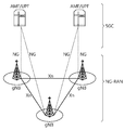
- NG-RAN New Generation Radio Access Network
- 5 illustrates functional partitioning between NG-RAN and 5GC.
- FIG. 6 illustrates a frame structure that can be applied in NR.
- FIG. 7 illustrates a slot structure of an NR frame.
- FIG. 9 is a diagram showing a difference between a core set in a conventional control region and an NR.
- FIG. 10 shows an example of a frame structure for a new radio access technology.
- FIG. 11 illustrates the structure of a self-contained slot.
- FIG. 13 illustrates a scenario in which three different bandwidth parts are set.
- FIG. 18 illustrates a method of monitoring a physical downlink control channel (PDCCH) of a terminal in a wireless communication system.
- PDCCH physical downlink control channel
- 20 is another example of a method of monitoring a PDCCH of a terminal in a wireless communication system.
- 21 is an example of a signaling method between a network (base station) and a terminal.
- FIG. 23 shows an example of a structure of a signal processing module.
- FIG. 24 shows another example of a structure of a signal processing module in a transmission device.
- 25 illustrates an example of a wireless communication device according to an embodiment of the present disclosure.
- 26 shows an example of the processor 2000.
- 29 shows another example of a wireless device applied to the present specification.
- FIG. 30 illustrates a portable device applied to the present specification.
- 31 illustrates a communication system 1 applied to the present specification.
- E-UTRAN Evolved-UMTS Terrestrial Radio Access Network
- LTE Long Term Evolution
- the E-UTRAN includes a base station (BS) 20 that provides a user equipment (UE) with a control plane and a user plane.
- the terminal 10 may be fixed or mobile, and other devices such as a mobile station (MS), a user terminal (UT), a subscriber station (SS), a mobile terminal (MT), a wireless device, a terminal, etc. It can be called a term.
- the base station 20 refers to a fixed station that communicates with the terminal 10, and may be referred to as an evolved-NodeB (eNB), a base transceiver system (BTS), an access point, gNB, etc. have.
- eNB evolved-NodeB
- BTS base transceiver system
- the base stations 20 may be connected to each other through an X2 interface.
- the base station 20 is connected to an Evolved Packet Core (EPC) 30 through an S1 interface, more specifically, a Mobility Management Entity (MME) through an S1-MME and a Serving Gateway (S-GW) through an S1-U.
- EPC Evolved Packet Core
- MME Mobility Management Entity
- S-GW Serving Gateway
- the EPC 30 is composed of MME, S-GW, and P-GW (Packet Data Network-Gateway).
- the MME has access information of the terminal or information on the capabilities of the terminal, and this information is mainly used for mobility management of the terminal.
- S-GW is a gateway with E-UTRAN as an endpoint
- P-GW is a gateway with PDN as an endpoint.
- the layers of the Radio Interface Protocol between the terminal and the network are L1 (Layer 1) based on the lower three layers of the Open System Interconnection (OSI) standard model, which is widely known in communication systems. It can be divided into L2 (layer 2) and L3 (layer 3). Among them, the physical layer belonging to the first layer provides information transfer service using a physical channel.
- the RRC (Radio Resource Control) layer located in Layer 3 plays a role of controlling radio resources between the UE and the network. To this end, the RRC layer exchanges RRC messages between the terminal and the base station.
- the 2 is a block diagram showing a radio protocol architecture for a user plane.
- 3 is a block diagram showing a radio protocol structure for a control plane.
- the user plane is a protocol stack for transmitting user data
- the control plane is a protocol stack for transmitting control signals.
- a physical layer provides an information transfer service to an upper layer using a physical channel.
- the physical layer is connected to an upper layer, a medium access control (MAC) layer, through a transport channel. Data moves between the MAC layer and the physical layer through the transport channel. Transport channels are classified according to how and with what characteristics data is transmitted through the air interface.
- MAC medium access control
- the physical channel may be modulated in an Orthogonal Frequency Division Multiplexing (OFDM) method, and time and frequency are used as radio resources.
- OFDM Orthogonal Frequency Division Multiplexing
- the functions of the MAC layer include mapping between a logical channel and a transport channel and multiplexing/demultiplexing of a MAC service data unit (SDU) belonging to the logical channel onto a transport block provided as a physical channel onto a transport channel.
- SDU MAC service data unit
- the MAC layer provides a service to the Radio Link Control (RLC) layer through a logical channel.
- RLC Radio Link Control
- the functions of the RLC layer include concatenation, segmentation, and reassembly of RLC SDUs.
- the RLC layer In order to ensure various QoS (Quality of Service) required by Radio Bearer (RB), the RLC layer has a Transparent Mode (TM), Unacknowledged Mode (UM), and Acknowledged Mode. , AM).
- TM Transparent Mode
- UM Unacknowledged Mode
- AM Acknowledged Mode.
- AM RLC provides error correction through automatic repeat request (ARQ).
- the Radio Resource Control (RRC) layer is defined only in the control plane.
- the RRC layer is in charge of controlling logical channels, transport channels, and physical channels in relation to configuration, re-configuration, and release of radio bearers.
- RB refers to a logical path provided by the first layer (PHY layer) and the second layer (MAC layer, RLC layer, PDCP layer) for data transmission between the terminal and the network.
- Functions of the Packet Data Convergence Protocol (PDCP) layer in the user plane include transmission of user data, header compression, and ciphering.
- Functions of the Packet Data Convergence Protocol (PDCP) layer in the control plane include transmission of control plane data and encryption/integrity protection.
- Establishing the RB refers to a process of defining characteristics of a radio protocol layer and channel to provide a specific service, and setting specific parameters and operation methods for each.
- the RB can be further divided into SRB (Signaling RB) and DRB (Data RB).
- SRB is used as a path for transmitting RRC messages in the control plane
- DRB is used as a path for transmitting user data in the user plane.
- the UE When an RRC connection is established between the RRC layer of the UE and the RRC layer of the E-UTRAN, the UE is in an RRC connected state, otherwise, it is in an RRC idle state.
- a downlink transport channel for transmitting data from a network to a terminal there are a broadcast channel (BCH) for transmitting system information, and a downlink shared channel (SCH) for transmitting user traffic or control messages.
- BCH broadcast channel
- SCH downlink shared channel
- downlink multicast or broadcast service traffic or control messages they may be transmitted through a downlink SCH or a separate downlink multicast channel (MCH).
- RACH random access channel
- SCH uplink shared channel
- BCCH Broadcast Control Channel
- PCCH Paging Control Channel
- CCCH Common Control Channel
- MCCH Multicast Control Channel
- MTCH Multicast Traffic. Channel
- the physical channel is composed of several OFDM symbols in the time domain and several sub-carriers in the frequency domain.
- One sub-frame is composed of a plurality of OFDM symbols in the time domain.
- a resource block is a resource allocation unit and is composed of a plurality of OFDM symbols and a plurality of sub-carriers.
- each subframe may use specific subcarriers of specific OFDM symbols (eg, the first OFDM symbol) of the corresponding subframe for the PDCCH (Physical Downlink Control Channel), that is, the L1/L2 control channel.
- TTI Transmission Time Interval
- new radio access technology new RAT, NR
- next-generation communications As more communication devices require a larger communication capacity, there is a need for improved mobile broadband communication compared to the existing radio access technology (RAT).
- RAT radio access technology
- massive Machine Type Communications (MTC) which provides various services anytime, anywhere by connecting multiple devices and objects, is one of the major issues to be considered in next-generation communications.
- MTC massive Machine Type Communications
- a communication system design in consideration of a service/terminal sensitive to reliability and latency is being discussed.
- URLLC Ultra-Reliable and Low Latency Communication
- NG-RAN New Generation Radio Access Network
- the NG-RAN may include a gNB and/or an eNB that provides a user plane and a control plane protocol termination to a terminal.
- 4 illustrates a case where only gNB is included.
- the gNB and the eNB are connected to each other through an Xn interface.
- the gNB and eNB are connected to the 5th generation core network (5G Core Network: 5GC) through the NG interface.
- 5G Core Network: 5GC 5th generation core network
- AMF access and mobility management function
- UPF user plane function
- 5 illustrates functional partitioning between NG-RAN and 5GC.
- the gNB is inter-cell radio resource management (Inter Cell RRM), radio bearer management (RB control), connection mobility control (Connection Mobility Control), radio admission control (Radio Admission Control), measurement setting and provision Functions such as (Measurement configuration & Provision) and dynamic resource allocation may be provided.
- AMF can provide functions such as NAS security and idle state mobility processing.
- UPF may provide functions such as mobility anchoring and PDU processing.
- SMF Session Management Function
- FIG. 6 illustrates a frame structure that can be applied in NR.
- a radio frame (hereinafter, may be abbreviated as a frame) may be used for uplink and downlink transmission in NR.
- the frame has a length of 10 ms and may be defined as two 5 ms half-frames (HF).
- the half-frame may be defined as five 1ms subframes (Subframe, SF).
- a subframe may be divided into one or more slots, and the number of slots within a subframe depends on Subcarrier Spacing (SCS).
- SCS Subcarrier Spacing
- Each slot includes 12 or 14 OFDM(A) symbols according to a cyclic prefix (CP). When a normal CP is used, each slot contains 14 symbols. When an extended CP is used, each slot includes 12 symbols.
- the symbol may include an OFDM symbol (or CP-OFDM symbol), an SC-FDMA symbol (or DFT-s-OFDM symbol).
- Table 1 below illustrates the subcarrier spacing configuration ⁇ .
- the following Table 2 exemplifies the number of slots in a frame (N frame ⁇ slot ), the number of slots in a subframe (N subframe ⁇ slot ), and the number of symbols in a slot (N slot symb ) according to the subcarrier spacing configuration ⁇ . .
- OFDM(A) numerology eg, SCS, CP length, etc.
- OFDM(A) numerology eg, SCS, CP length, etc.
- the (absolute time) section of the time resource eg, SF, slot or TTI
- TU Time Unit
- FIG. 7 illustrates a slot structure of an NR frame.
- the slot may include a plurality of symbols in a time domain (domain). For example, in the case of a normal CP, one slot includes 7 symbols, but in the case of an extended CP, one slot may include 6 symbols.
- the carrier may include a plurality of subcarriers in the frequency domain.
- Resource Block (RB) may be defined as a plurality of (eg, 12) consecutive subcarriers in the frequency domain.
- the BWP (Bandwidth Part) may be defined as a plurality of consecutive (P)RBs in the frequency domain, and may correspond to one numerology (eg, SCS, CP length, etc.).
- the carrier may contain up to N (eg, 5) BWPs. Data communication is performed through the activated BWP, and only one BWP can be activated to one terminal.
- Each element in the resource grid is referred to as a resource element (RE), and one complex symbol may be mapped.
- RE resource element
- the physical downlink control channel may be composed of one or more control channel elements (CCEs) as shown in Table 3 below.
- CCEs control channel elements
- the PDCCH may be transmitted through a resource consisting of 1, 2, 4, 8 or 16 CCEs.
- the CCE is composed of six REGs (resource element group), and one REG is composed of one resource block in the frequency domain and one orthogonal frequency division multiplexing (OFDM) symbol in the time domain.
- OFDM orthogonal frequency division multiplexing
- Monitoring refers to decoding each PDCCH candidate according to a downlink control information (DCI) format.
- the UE monitors the set of PDCCH candidates in one or more core sets (CORESET, described below) on the activation DL BWP of each activated serving cell for which PDCCH monitoring is configured according to the corresponding search space set.
- CORESET core sets
- a new unit called a control resource set (CORESET, core set) may be introduced.
- the UE can receive the PDCCH in the core set.
- the core set may be composed of N CORESET RB resource blocks in the frequency domain, and N CORESET symb ⁇ ⁇ 1, 2, 3 ⁇ symbols in the time domain.
- N CORESET RB and N CORESET symb may be provided by the base station through an upper layer signal.
- a plurality of CCEs may be included in the core set.
- One CCE may be composed of a plurality of REG (resource element groups), and one REG may include one OFDM symbol in the time domain and 12 resource elements in the frequency domain.
- the UE may attempt to detect PDCCH in units of 1, 2, 4, 8 or 16 CCEs within the core set.
- PDCCH candidates One or a plurality of CCEs that may attempt PDCCH detection may be referred to as PDCCH candidates.
- the terminal may be configured with a plurality of core sets.
- FIG. 9 is a diagram showing a difference between a core set in a conventional control region and an NR.
- a control area 800 in a conventional wireless communication system (eg, LTE/LTE-A) is configured over the entire system band used by the base station. Except for some terminals that support only a narrow band (e.g., eMTC/NB-IoT terminals), all terminals must receive radio signals of the entire system band of the base station in order to properly receive/decode control information transmitted by the base station. Should have been.
- the core sets 801, 802, and 803 may be referred to as radio resources for control information that the terminal needs to receive, and may use only part of the system band instead of the entire system band in the frequency domain. In addition, only some of the symbols in the slot may be used in the time domain.
- the base station may allocate a core set to each terminal, and transmit control information through the allocated core set. For example, in FIG. 9, the first core set 801 may be allocated to terminal 1, the second core set 802 may be allocated to the second terminal, and the third core set 803 may be allocated to terminal 3. have.
- the terminal in the NR can receive the control information of the base station even if the entire system band is not necessarily received.
- the core set there may be a terminal-specific core set for transmitting terminal-specific control information and a common core set for transmitting common control information to all terminals.
- the resource may include at least one of a resource in a time domain, a resource in a frequency domain, a resource in a code domain, and a resource in a spatial domain.
- FIG. 10 shows an example of a frame structure for a new radio access technology.
- a structure in which a control channel and a data channel are time division multiplexed (TDM) within one TTI is considered as one of the frame structures as shown in FIG. 10 for the purpose of minimizing latency. Can be.
- a shaded area indicates a downlink control area
- a black area indicates an uplink control area.
- An area without indication may be used for downlink data (DL data) transmission or for uplink data (UL data) transmission.
- the characteristic of this structure is that downlink (DL) transmission and uplink (UL) transmission are sequentially performed within one subframe, and DL data is transmitted within a subframe, and UL ACK/ Acknowledgment/Not-acknowledgement (NACK) can also be received. As a result, it is possible to reduce the time taken to retransmit data when a data transmission error occurs, thereby minimizing the latency of the final data transmission.
- the base station and the terminal switch from a transmission mode to a reception mode or a time gap for a process of switching from a reception mode to a transmission mode. ) Is required.
- some OFDM symbols at a time point at which the DL to UL is switched in the self-contained subframe structure may be set as a guard period (GP).
- FIG. 11 illustrates the structure of a self-contained slot.
- all of a DL control channel, DL or UL data, and UL control channel may be included in one slot.
- the first N symbols in a slot may be used to transmit a DL control channel (hereinafter, a DL control region), and the last M symbols in a slot may be used to transmit a UL control channel (hereinafter, a UL control region).
- N and M are each an integer of 0 or more.
- a resource region (hereinafter, a data region) between the DL control region and the UL control region may be used for DL data transmission or UL data transmission.
- the following configuration may be considered. Each section was listed in chronological order.
- DL area (i) DL data area, (ii) DL control area + DL data area
- UL area (i) UL data area, (ii) UL data area + UL control area
- the PDCCH may be transmitted in the DL control region, and a physical downlink shared channel (PDSCH) may be transmitted in the DL data region.
- a physical uplink control channel (PUCCH) may be transmitted in the UL control region, and a physical uplink shared channel (PUSCH) may be transmitted in the UL data region.
- DCI downlink control information
- DL data scheduling information for example, DL data scheduling information, UL data scheduling information, and the like
- uplink control information for example, positive acknowledgment/negative acknowledgment (ACK/NACK) information for DL data, channel state information (CSI) information, scheduling request (SR), and the like may be transmitted.
- ACK/NACK positive acknowledgment/negative acknowledgment
- CSI channel state information
- SR scheduling request
- the GP provides a time gap in the process of switching the base station and the terminal from the transmission mode to the reception mode or the process of switching from the reception mode to the transmission mode. Some symbols at a time point at which the DL to UL is switched within a subframe may be set as a GP.
- the wavelength is shortened, making it possible to install multiple antenna elements in the same area. That is, in the 30GHz band, the wavelength is 1cm, and a total of 100 antenna elements can be installed in a two-dimensional arrangement at 0.5 wavelength intervals on a 5 by 5 cm panel. Therefore, in mmW, a plurality of antenna elements are used to increase beamforming (BF) gain to increase coverage or to increase throughput.
- BF beamforming
- TXRU transceiver unit
- independent beamforming is possible for each frequency resource.
- TXRUs to install TXRUs on all of the 100 antenna elements, there is a problem that the effectiveness is inferior in terms of price. Therefore, a method of mapping a plurality of antenna elements to one TXRU and adjusting the direction of a beam using an analog phase shifter is considered.
- This analog beamforming method has a disadvantage in that it is not possible to perform frequency selective beamforming because only one beam direction can be created in the entire band.
- Hybrid beamforming (hybrid BF) having B TXRUs, which is a smaller number than Q antenna elements, may be considered as an intermediate form between digital beamforming (digital BF) and analog beamforming (analog BF).
- digital BF digital beamforming
- analog beamforming analog beamforming
- the directions of beams that can be transmitted at the same time are limited to B or less.
- the hybrid beamforming structure may be represented by N TXRUs and M physical antennas.
- digital beamforming for L data layers to be transmitted from the transmitter can be expressed as an N by L matrix, and the converted N digital signals are then converted to analog signals through TXRU. After conversion, analog beamforming expressed as an M by N matrix is applied.
- System information of the NR system may be transmitted in a broadcasting method.
- analog beams belonging to different antenna panels within one symbol may be simultaneously transmitted, and a reference signal transmitted by applying a single analog beam (corresponding to a specific antenna panel) to measure channels for each analog beam.
- RS a method of introducing a beam reference signal
- the BRS may be defined for a plurality of antenna ports, and each antenna port of the BRS may correspond to a single analog beam.
- a synchronization signal or xPBCH may be transmitted by applying all analog beams in an analog beam group so that any terminal can receive it well.
- a synchronization signal block (SSB, or may also be referred to as a synchronization signal and physical broadcast channel (SS/PBCH)) in the time domain is 0 to 3 in the synchronization signal block. It may be composed of four OFDM symbols numbered in ascending order, a primary synchronization signal (PSS), a secondary synchronization signal (SSS), and a demodulation reference signal (DMRS) and Associated PBCH can be mapped to symbols. As described above, the synchronization signal block may also be expressed as an SS/PBCH block.
- PSS primary synchronization signal
- SSS secondary synchronization signal
- DMRS demodulation reference signal
- Associated PBCH can be mapped to symbols.
- the synchronization signal block may also be expressed as an SS/PBCH block.
- a plurality of synchronization signal blocks may be transmitted at different times, and SSBs may be used to perform initial access (IA), serving cell measurement, etc., so transmission with other signals
- IA initial access
- serving cell measurement etc.
- the network may broadcast the transmission time and resource information of the SSB or may indicate through UE-specific RRC signaling.
- a beam-based transmission/reception operation may be performed.
- a process of finding a new beam may be performed through a process called beam failure recovery (BFR).
- BFR beam failure recovery
- the BFR is not a process of declaring an error/failure for a link between a network and a terminal, it may be assumed that the current connection with the serving cell is maintained even if the BFR process is performed.
- the BFR process measurement is performed on different beams set by the network (the beam can be expressed as a port of a CSI-RS or a synchronization signal block (SSB) index, etc.), and the best beam is provided to the corresponding terminal. You can choose.
- the UE may perform the BFR process in a manner that performs a RACH process associated with the corresponding beam.
- the TCI state may be set for each core set of the control channel, and a parameter for determining a reception (Rx) beam of the terminal may be determined based on the TCI state.
- the terminal may receive three or less core sets.
- the terminal may receive the following information.
- Core set index p (eg, one of 0 to 11, the index of each core set in the BWPs of one serving cell may be uniquely determined
- TCI transmission configuration indication
- the two antenna ports are said to be in a quasi-common position (QCL).
- QCL quasi-common position
- a and B are QCLed may mean that A and B have undergone similar channel conditions, and thus, channel information estimated to detect A is also useful for detecting B.
- the channel condition may be defined by, for example, a Doppler shift, a Doppler spread, an average delay, a delay spread, a spatial reception parameter, and the like.
- The'TCI-State' parameter associates one or two downlink reference signals with a corresponding QCL type (there are QCL types A, B, C, and D, see Table 4).
- Each'TCI-State' is for establishing a quasi-collocation (QCL) relationship between one or two downlink reference signals and a DM-RS port of a PDSCH (or PDCCH), or a CSI-RS port of a CSI-RS resource. May contain parameters.
- QCL quasi-collocation
- the terminal in each DL BWP set to the terminal in one serving cell, the terminal may be provided with 10 or less search space sets. For each search space set, the terminal may be provided with at least one of the following information.
- search space set index s (0 ⁇ s ⁇ 40), 2) association between core set P and search space set s, 3) PDCCH monitoring period and PDCCH monitoring offset (slot unit), 4) within a slot PDCCH monitoring pattern (e.g., indicating the first symbol of the core set in the slot for PDCCH monitoring), 5) the number of slots in which the search space set s exists, 6) the number of PDCCH candidates per CCE aggregation level, 7) search Information indicating whether the space set s is CSS or USS, etc.
- Coreset #0 in the NR may be configured by PBCH (or terminal-specific signaling for handover or PSCell configuration or BWP configuration).
- the search space (SS) set #0 set by the PBCH may have different monitoring offsets (eg, slot offset, symbol offset) for each associated SSB. This may be necessary to minimize a search space occasion that the UE should monitor. Or it means providing a beam sweeping control/data area that can perform control/data transmission according to each beam so that communication with the terminal can be continued in a situation where the best beam of the terminal dynamically changes. May also be needed.
- a terminal receives information from a base station through a downlink (DL), and the terminal transmits information to a base station through an uplink (UL).
- the information transmitted and received by the base station and the terminal includes data and various control information, and various physical channels exist according to the type/use of information transmitted and received by them.
- the terminal newly entering the cell performs an initial cell search operation such as synchronizing with the base station (S11).
- the UE receives a Primary Synchronization Channel (PSCH) and a Secondary Synchronization Channel (SSCH) from the base station, synchronizes with the base station, and acquires information such as cell identity (cell identity).
- the terminal may obtain intra-cell broadcast information by receiving a PBCH (Physical Broadcast Channel) from the base station.
- the UE may check a downlink channel state by receiving a DL RS (Downlink Reference Signal) in the initial cell search step.
- PBCH Physical Broadcast Channel
- the UE may receive more detailed system information by receiving a Physical Downlink Control Channel (PDCCH) and a Physical Downlink Control Channel (PDSCH) corresponding thereto (S12).
- PDCCH Physical Downlink Control Channel
- PDSCH Physical Downlink Control Channel
- the terminal may perform a random access procedure to complete the access to the base station (S13 to S16).
- the UE may transmit a preamble through a physical random access channel (PRACH) (S13), and receive a random access response (RAR) for the preamble through a PDCCH and a corresponding PDSCH (S14).
- PRACH physical random access channel
- RAR random access response
- the UE transmits a PUSCH (Physical Uplink Shared Channel) using scheduling information in the RAR (S15), and may perform a contention resolution procedure such as a PDCCH and a corresponding PDSCH (S16).
- PUSCH Physical Uplink Shared Channel
- the UE may perform PDCCH/PDSCH reception (S17) and PUSCH/PUCCH (Physical Uplink Control Channel) transmission (S18) as a general uplink/downlink signal transmission procedure.
- Control information transmitted by the terminal to the base station is referred to as UCI (Uplink Control Information).
- UCI includes HARQ ACK/NACK (Hybrid Automatic Repeat and ReQuest Acknowledgement/Negative-ACK), SR (Scheduling Request), CSI (Channel State Information), and the like.
- CSI includes Channel Quality Indicator (CQI), Precoding Matrix Indicator (PMI), Rank Indication (RI), and the like.
- UCI is generally transmitted through PUCCH, but may be transmitted through PUSCH when control information and data are to be transmitted at the same time.
- the terminal may aperiodically transmit UCI through the PUSCH according to the request/instruction of the network.
- the terminal's reception and transmission bandwidth need not be as wide as the cell's bandwidth and can be adjusted: the width can be commanded to be changed (e.g., a period of low activity to save power During contraction), the location in the frequency domain can be moved (eg, to increase scheduling flexibility), and the subcarrier spacing can be commanded to change (eg, to allow different services).
- the subset of the total cell bandwidth of the cell is referred to as a bandwidth part (BWP), and the BA is obtained by setting the BWP(s) to the UE and notifying the UE that it is currently active among the set BWPs.
- the BA When the BA is set, the terminal only needs to monitor the PDCCH on one active BWP.
- the BWP inactive timer (independent of the DRX inactive timer described above) is used to switch the active BWP to the default BWP: the timer restarts when the PDCCH decoding succeeds, and when the timer expires, switching to the default BWP occurs. do.
- FIG. 13 illustrates a scenario in which three different bandwidth parts are set.
- BWP 1 , BWP 2 and BWP 3 are set on time-frequency resources.
- BWP 1 has a width of 40 MHz and a subcarrier spacing of 15 kHz
- BWP 2 has a width of 10 MHz and a subcarrier spacing of 15 kHz
- BWP 3 may have a width of 20 MHz and a subcarrier spacing of 60 kHz.
- each of the bandwidth parts may have different widths and/or different subcarrier spacings.
- the DRX cycle may be composed of'On Duration (on-interval, which may be referred to as a DRX ON interval hereinafter)' and'Opportunity for DRX (opportunity for DRX)'.
- the DRX cycle defines the time interval at which the'on-interval' repeats periodically.
- The'on-interval' represents a time period during which the UE monitors to receive the PDCCH.
- the UE performs PDCCH monitoring during the'on-period'. If there is a PDCCH successfully detected during PDCCH monitoring, the UE operates an inactivity timer and maintains an awake state. On the other hand, if there is no PDCCH successfully detected during PDCCH monitoring, the UE enters a sleep (sleep) state after the'on-section' ends.
- Table 5 shows the process of the terminal related to DRX (RRC_CONNECTED state).
- DRX configuration information is received through higher layer (eg, RRC) signaling, and whether DRX ON/OFF may be controlled by the DRX command of the MAC layer.
- RRC Radio Resource Control
- the MAC-CellGroupConfig may include configuration information required to set a medium access control (MAC) parameter for a cell group.
- MAC-CellGroupConfig may also include configuration information about DRX.
- MAC-CellGroupConfig defines DRX, and may include information as follows.
- -Value of drx-InactivityTimer Defines the length of the time interval in which the UE is awake after the PDCCH opportunity in which the PDCCH indicating initial UL or DL data is detected
- -Value of drx-HARQ-RTT-TimerDL Defines the length of the maximum time interval from receiving the initial DL transmission until the DL retransmission is received.
- the UE performs PDCCH monitoring at every PDCCH opportunity while maintaining the awake state.
- the terminal is the starting point of the DRX cycle, the duration of the DRX cycle, the starting point of the on-duration timer, and the on-section according to the DRX configuration. You can know the duration of the timer. Thereafter, the UE attempts to receive/detection for scheduling information (i.e., PDCCH) within the on-period of each DRX cycle (this may be expressed as monitoring scheduling information).
- scheduling information i.e., PDCCH
- scheduling information (PDCCH) is detected within the on-period of the DRX cycle, an inactivity timer is activated, and detection of another scheduling information during a given inactivation timer period (time period in which the inactivation timer operates) is performed. Will try. In this case, it may be referred to as an active time including the on-period and the deactivation timer period in which the terminal performs a signal reception/detection operation. If scheduling information (DCI format) is not detected within the on-period, only the on-period may be an activation time.
- DCI format scheduling information
- the terminal When the deactivation timer expires without receiving/detecting an additional signal (control signal or data), the terminal provides scheduling information and corresponding response from the time deactivation timer expires until the DRX on duration of the next DRX cycle starts. DL reception/UL transmission is not performed.
- the period adjustment of the DRX cycle, the period adjustment of the on-section timer/deactivation timer, etc. play an important role in determining whether the terminal sleeps.
- the network may be configured to frequently sleep the terminal or to constantly monitor scheduling information. This can serve as a factor that determines whether or not to save power of the terminal.
- WUS wake up signal
- PDCCH Physical Downlink Control Channel
- the terminal When the terminal performs power saving-related operations after receiving power saving (PwsS)-related settings from the base station after random access (RA), it may perform the proposal, embodiment, or operation of the present disclosure to be described later. I can. After the random access, when the base station provides/sets power saving-related settings to the terminal and performs power-saving-related operations, a proposal, an embodiment, or an operation of the present disclosure to be described later may be performed.
- PwsS power saving-related operations after receiving power saving
- RA random access
- PDCCH monitoring is not performed by various factors as well as a slot format indicator (SFI) (in other words,'cannot be performed', or'not required to perform', or'performed It can be expressed as'difficult to do', and the same applies hereinafter) resources may occur.
- SFI slot format indicator
- WUS monitoring method and a coping method are proposed for each case.
- C-DRX operation for example, Connected Mode Discontinuous Reception (C-DRX) operation (DRX) is introduced to save power of the terminal.
- C-DRX operation if there is no PDCCH reception within the on-duration defined for each DRX cycle, the UE enters a sleep mode (sleep mode) until the next DRX cycle and performs transmission/reception. It works in a way that doesn't.
- an inactivity timer, retransmission timer, etc. are operated to increase the active time. If there is no additional data reception within the activation time, the next DRX You can perform a sleep operation up to the operation.
- a wake up signal (WUS) was introduced to obtain a power saving gain in addition to the existing C-DRX operation.
- WUS plays a role of determining whether to perform PDCCH monitoring in the on-section of each DRX cycle (or multiple DRX cycles), and when WUS cannot be detected (at a predetermined or indicated WUS monitoring opportunity), A sleep operation can be maintained without performing PDCCH monitoring in one or more DRX cycles linked to the corresponding WUS.
- a WUS monitoring opportunity may be determined based on, for example, a message for setting a search space (set).
- the WUS may be a DCI format including a wake-up indication.
- DCI format 2_6 is a DCI format used to inform the terminal of power saving information outside the DRX activation time, and DCI format 2_6 includes, for example, a wake-up instruction (1 bit), and dormancy of the secondary cell (dormancy). ), etc. may be included.
- This DCI format is transmitted through the PDCCH.
- the WUS monitoring may be expressed as one of PDCCH monitoring.
- the opportunity to monitor this WUS can be determined by a message that sets up a search space (set).
- the following table is an example of a message for setting a search space (set).
- 'duration' is the number of consecutive slots that a SearchSpace lasts in every occasion, ie, a periodicity and an offset. upon every period as given in the periodicityAndOffset).
- 'MonitoringSlotPeriodicityAndOffset' indicates slots for PDCCH monitoring composed of periodicity and offset.
- DCI format 2_1 only values of'sl1','sl2', or'sl4' may be applicable.
- DCI format 2_0 only values'sl1','sl2','sl4','sl5','sl8','sl10','sl16' and'sl20' may be applicable.
- 'MonitoringSymbolsWithinSlot' represents a first symbol (see SlotPeriodicityAndOffset and duration monitoring) for PDCCH monitoring in a slot configured for PDCCH monitoring.
- the most significant bit (left) bit represents the first OFDM symbol in the slot, and the next most significant bit (left) bit represents the second OFDM symbol in the slot.
- the bit(s) set to 1 identifies the first OFDM symbol(s) of the core set within the slot.
- DCI format 2_0 when the core set section identified by'controlResourceSetId' displays 3 symbols, the first one symbol is applied, and when the core set section identified by controlResourceSetId displays 2 symbols, the first two symbols are displayed. Apply. When the core set section identified by controlResourceSetId represents 1 symbol, the first 3 symbols are applied.
- 'NrofCandidates-SFI' indicates the number of PDCCH candidates for DCI format 2-0 for a set aggregation level. If there is no aggregation level, the terminal does not search for candidates having the corresponding aggregation level.
- the network can set only one aggregation level and a corresponding number of candidates.
- 'NrofCandidates' represents the number of PDCCH candidates per aggregation level.
- the set number of candidates and aggregation levels can be applied to all formats unless a specific value is specified or a value for each format is provided.
- 'monitoringSlotPeriodicityAndOffset' in Table 6 can inform the slots for PDCCH monitoring based on periodicity and offset, and these slots can be said to correspond to an opportunity for PDCCH monitoring.
- 'duration' indicates consecutive slots in which the search space lasts at each opportunity.
- reference numerals 151 and 152 may be referred to as PDCCH monitoring opportunities set by'monitoringSlotPeriodicityAndOffset', and a search space is continued in three consecutive slots at each PDCCH monitoring opportunity.
- the PDCCH monitoring opportunity for monitoring WUS is the start slot of the DRX on period (i.e., the slot where the drx-onDurationTimer starts, 153) and the offset (ps-offset) value. It may be limited to those within the interval between the times 154 indicated by (let's call this a WUS monitoring window). That is, in FIG. 15, 151 is outside the WUS monitoring window, and 152 is inside the WUS monitoring window. Accordingly, the UE may perform PDCCH monitoring for WUS detection only at the PDCCH monitoring opportunity corresponding to 152.
- the terminal may perform a necessary operation in the DRX ON section based on the WUS. For example, when the WUS indicates a wake-up of the terminal, it can wake up in the DRX ON period and perform PDCCH monitoring for detection of a general DCI format other than WUS (that is, it may be expressed as starting drx-onDurationTimer. ).
- the transmission direction (e.g., downlink/uplink) of each slot and symbol can be dynamically changed, and the corresponding operation To perform the slot format indicator (SFI) may be delivered through DCI format 2_0.
- SFI slot format indicator
- DCI format 2_0 may be defined as follows.
- DCI format 2_0 is a DCI format used to inform the slot format, and the following information may be transmitted through DCI format 2_0 CRC scrambled by SFI-RNTI.
- Slot format indicator 1 slot format indicator 2, ... , Slot format indicator N.
- the size of DCI format 2_0 can be set by an upper layer and can be up to 128 bits.
- the transmission direction in the slot/symbol designated as “flexible” through RRC signaling can be dynamically changed by DCI format 2_0, and is designated as UL by RRC and DCI format 2_0. PDCCH monitoring is not performed in the slot/symbol.
- the WUS monitoring opportunity may be indicated to the connected mode terminal in advance (by setting an offset method/search space set (SS set), etc.).
- the monitoring opportunity may include not only a time resource for performing WUS monitoring, but also a frequency resource.
- the WUS monitoring opportunity is not only a time domain resource such as a slot/symbol(s) that monitors the corresponding WUS core set, but also the corresponding core set.
- the frequency domain resource of may also belong to the category of monitoring opportunities. That is, in the present disclosure, resources required for the terminal to configure a search space for WUS monitoring (eg, a core set and a starting position of the core set) may be regarded as a WUS monitoring opportunity.
- the SFI may be set by (terminal common/terminal specific) RRC signaling and/or DCI format 2_0.
- the UE can know whether UL/DL/flexible per slot/symbol is basic by cell-specific RRC signaling (TDD-UL-DL-configurationCommon), and additionally UE-specific RRC signaling Whether UL/DL/flexible for a resource defined as “flexible” in the cell-specific RRC signaling can be indicated by (TDD-UL-DL-ConfigDedicated). Thereafter, the UE may additionally receive UL/DL/flexible indication through DCI format 2_0 for a resource indicated as “flexible” by RRC signaling (cell-specific & UE-specific RRC signaling).
- the UE may perform PDCCH monitoring in a resource indicated by downlink (DL) by RRC signaling and/or DCI.
- DL downlink
- the instruction is flexible by RRC signaling, but does not receive additional DCI, PDCCH monitoring may be performed even in the resource indicated by the flexible.
- UL/DL/flexible for each symbol in one slot is defined as a slot format, for example, as shown in the following table.
- the network may define a slot format combination based on the slot format defined as in the above table.
- the slot format combination may be composed of slot formats corresponding to the number of slots indicated by the combination.
- the maximum number of slots that one slot format combination can have may be, for example, 512 slots.
- the number of slots indicated by each slot format combination may be defined as an effective period of the corresponding slot format combination.
- Case 1-1) The valid interval of the previously received SFI DCI (e.g., DCI format 2_0) is maintained until the next DRX on-interval (or the WUS monitoring opportunity linked to the next DRX on-interval), and the WUS monitoring opportunity is ( When indicated by downlink) by RRC signaling and/or DCI 2_0.
- SFI DCI e.g., DCI format 2_0
- case 2 may be as follows. As can be seen from the following, if the SSB position indicated by the network and the PDCCH monitoring opportunity overlap, if there is a resource that overlaps with the SSB resource among resource elements in the PDCCH candidate, the UE for the corresponding PDCCH candidate Do not perform monitoring.
- the terminal in monitoring the PDCCH candidate in the slot, the terminal i) receives'ssb-PositionsInBurst' in system information block 1 (SIB1) and ii) does not receive'ssb-PositionsInBurst' in'ServingCellConfigCommon' for a serving cell. Iii) does not monitor the PDCCH candidate in the Type0-PDCCH CSS set; iv) at least one resource element for the PDCCH candidate is at least one resource corresponding to the SS/PBCH block index provided by'ssb-PositionsInBurst' in SIB1 If the element overlaps, the UE does not need to monitor the PDCCH candidate.
- SIB1 system information block 1
- the terminal i) receives'ssb-PositionsInBurst' in'ServingCellConfigCommon' for the serving cell, ii) does not monitor the PDCCH candidate in the Type0-PDCCH CSS set, and iii) at least one resource element for the PDCCH candidate is If the SIB1 overlaps with at least one resource element corresponding to the SS/PBCH block index provided by'ssb-PositionsInBurst', the UE does not need to monitor the PDCCH candidate.
- the UE When the LTE CRS resource indicated by the network and the PDCCH monitoring opportunity overlap, the UE does not perform monitoring on the corresponding PDCCH candidate if there is a resource that overlaps the LTE CRS resource among resource elements in the PDCCH candidate.
- the UE in monitoring of a PDCCH candidate in a slot, when at least one resource element of a PDCCH candidate on a serving cell overlaps with at least one resource element of'lte-CRS-ToMatchAround', the UE does not need to monitor the PDCCH candidate.
- Each of the following methods may be applied for each case (or sub-case), or one method may be applied to a plurality of cases, and the case to which the network is applied to all or part of the following methods is indicated by higher layer signaling, etc. It can also be directed through. Also, the following methods may be implemented alone or in combination.
- the following methods can also be applied to a case where a terminal other than the cases listed above cannot perform WUS monitoring. That is, when a valid WUS monitoring opportunity has been set, but the WUS monitoring cannot be performed due to various reasons (e.g., overlaps with resources allocated for other purposes) from the valid WUS monitoring opportunity, or when WUS monitoring is not required. , At least one of the methods described below may be applied.
- the terminal when the terminal cannot perform WUS monitoring, it may mean that the terminal does not require PDCCH monitoring for WUS (DCI format 2_6) detection.
- the network may instruct to apply Method 1 to a terminal with a small amount of scheduled or expected traffic.
- the terminal receiving the indication may determine whether WUS monitoring is possible (whether WUS is a resource to which WUS can be transmitted) based on the UL/DL configuration, SSB configuration, LTE CRS configuration, and the like that are previously indicated.
- the terminal receives configuration information related to the WUS monitoring method (S161).
- the setting information may indicate, for example, Method 1 described above.
- the terminal determines whether WUS monitoring can be performed on resources at the WUS monitoring scheduled time point (S162). For example, it may be determined whether the corresponding resource is indicated as uplink by the above-described higher layer signal.
- the terminal If it is determined that WUS monitoring can be performed on the resources at the WUS monitoring scheduled time point, the terminal performs WUS monitoring and PDCCH monitoring of the associated DRX cycle (S163).
- the UE does not perform WUS monitoring and PDCCH monitoring of the associated DRX cycle (S164).
- Method 2 Method for the terminal to wake up when WUS cannot be transmitted at the monitoring opportunity.
- Method 2 may be used for the purpose of preventing an increase in delay due to skipping PDCCH monitoring. If a WUS monitoring opportunity is set in an area in which WUS cannot be transmitted (or a resource area in which the terminal is not required to monitor WUS) (instructed by the network or by a predefined definition), the DRX linked to the WUS without WUS monitoring PDCCH monitoring can be performed in the on-section of the cycle. The network performs a power saving operation, but the PDCCH monitoring can be induced to a terminal in which data transmission and reception is expected through the method 2 method.
- the terminal receives configuration information related to the WUS monitoring method (S171).
- the setting information may indicate, for example, Method 2 described above.
- the terminal determines whether WUS monitoring can be performed on resources at the WUS monitoring scheduled time point (S172). For example, it may be determined whether the corresponding resource is indicated as uplink by the above-described higher layer signal.
- the terminal If it is determined that WUS monitoring can be performed in the resources at the WUS monitoring scheduled time point, the terminal performs WUS monitoring and PDCCH monitoring of the associated DRX cycle (S173).
- the terminal may not perform WUS monitoring and may only perform PDCCH monitoring of the associated DRX cycle (S174).
- S174 PDCCH monitoring of the associated DRX cycle
- FIG. 16 when it is determined that WUS monitoring cannot be performed on resources at the time when WUS monitoring is scheduled, neither WUS monitoring nor PDCCH monitoring of the associated DRX cycle is performed, but in FIG. 17, in this case, WUS monitoring is performed. There is a difference in performing only PDCCH monitoring of the associated DRX cycle without doing so.
- FIG. 18 illustrates a method of monitoring a physical downlink control channel (PDCCH) of a terminal in a wireless communication system.
- PDCCH physical downlink control channel
- the terminal receives first configuration information indicating the location of a synchronization signal/physical broadcast channel block (SSB) (S181).
- SSB synchronization signal/physical broadcast channel block
- the terminal may receive'ssb-PositionsInBurst' (corresponding to first configuration information) through system information block 1 (SIB1).
- SIB1 system information block 1
- the first setting information may indicate, for example, a position of the time domain of the SSB transmitted within a half frame.
- the terminal may receive the first configuration information through an RRC message (referred to as “ServingCellConfigCommon”) used to configure cell-specific parameters of the serving cell of the terminal.
- the terminal receives second configuration information indicating a monitoring opportunity for detecting a wake up signal (WUS) (S182).
- the wake-up signal may be, for example, first downlink control information (DCI) including a wake-up indication.
- the first DCI may be, for example, DCI format 2_6.
- the monitoring opportunity may be located within a predetermined time from the start of the next DRX-on period. This may mean that the monitoring opportunity is a valid monitoring opportunity in terms of time. This has been described in detail with reference to FIG. 15.
- the second setting information may be included in the message for setting the above-described search space (set).
- the monitoring opportunity may be defined by'monitoringSlotPeriodicityAndOffset','duration', etc. included in a message for setting a search space (set).
- the terminal determines whether the resource constituting the monitoring opportunity overlaps the SSB resource (S183). This may mean determining whether the first PDCCH monitoring for detecting the wake-up signal is possible at the monitoring opportunity (whether monitoring the first PDCCH is an exceptional situation difficult).
- the exceptional circumstances can be defined in advance. For example, if a resource constituting the monitoring opportunity and a resource to be used for receiving an essential signal such as an SSB overlap, it may be determined that PDCCH monitoring is difficult because the SSB should be received rather than monitoring the PDCCH at the monitoring opportunity. (This may be expressed that PDCCH monitoring is not required at the monitoring opportunity).
- the first PDCCH monitoring is not required at the monitoring opportunity.
- the UE performs the second PDCCH monitoring in the next discontinuous reception (DRX)-on period ( S184). After wake-up, the UE may perform PDCCH monitoring for all set search space sets.
- the second PDCCH monitoring may be a PDCCH monitoring for detecting a second DCI other than the first DCI.
- the second DCI may be, for example, general scheduling information such as DCI format 0 and DCI format 1 (in addition to DCIs excluding the first DCI). If the first PDCCH monitoring for detecting the wake-up signal is not required at the monitoring opportunity, the UE does not perform the first PDCCH monitoring at the monitoring opportunity.
- the terminal when a WUS opportunity is set in an area in which WUS cannot be transmitted (or a resource area in which the terminal is not required to monitor DCI), the terminal does not perform WUS monitoring (first PDCCH monitoring). Instead, the second PDCCH monitoring may be performed in the on-section of the DRX cycle linked to the corresponding WUS.
- a plurality of monitoring opportunities may be set.
- the second PDCCH monitoring is performed in the next discontinuous reception (DRX)-on period. can do. That is, a plurality of (valid) monitoring opportunities set by the network (e.g., located in front of the next DRX-on period, but a certain time from the DRX-on period (the certain time may be set or predetermined by the network).
- the Second PDCCH monitoring may be performed.
- the monitoring opportunity may be provided as two monitoring opportunities, such as a first monitoring opportunity and a second monitoring opportunity.
- the first PDCCH monitoring is not required at the first monitoring opportunity, and even one of the resource elements constituting the second monitoring opportunity is SSB If the resource element overlaps, the first PDCCH monitoring is not required at the second monitoring opportunity. In this way, if the first PDCCH monitoring is not required for all of the plurality of monitoring opportunities, the UE may perform the second PDCCH monitoring in the next DRX-on period.
- WUS monitoring opportunities 191, 192, and 193 may be set to a terminal.
- WUS monitoring opportunities may be set/instructed through a message for setting the above-described search space (set).
- SSB (SS/PBCH block) resources 194 may be configured for the terminal.
- the terminal may set/receive SSB resources through system information (ssb-PositionsInBurst in SIB1) or set/receive SSB resources through common configuration information (ssb-PositionsInBurst in ServingCellConfigCommon) for a serving cell.
- a specific WUS monitoring opportunity for example, a portion overlapping with the SSB resource 194 may occur in the WUS monitoring opportunity 192 located before the second DRX on-period.
- the UE does not perform PDCCH monitoring for WUS detection at the WUS monitoring opportunity 192.
- PDCCH monitoring for detecting a general DCI format other than WUS is performed in the second DRX on-section.
- PDCCH monitoring for WUS detection is performed, and according to the result, whether to perform PDCCH monitoring in the corresponding DRX on-section is determined. You can decide.
- FIG. 19 a case where there is one WUS monitoring opportunity in front of the second DRX ON period and the WUS monitoring opportunity overlaps the SSB resource is illustrated, but this is not a limitation. That is, there may be a plurality of WUS monitoring opportunities in front of the second DRX on period, and overlap with at least one of an uplink resource, an SSB resource, and an LTE CRS resource may occur in all of the plurality of WUS monitoring opportunities. In this case, the UE does not perform PDCCH monitoring for WUS detection at the plurality of WUS monitoring opportunities, and performs PDCCH monitoring for general DCI format detection other than WUS in the second DRX on-section.
- 20 is another example of a method of monitoring a PDCCH of a terminal in a wireless communication system.
- the terminal receives configuration information indicating a long term evolution (LTE) cell-specific reference signal (CRS) resource (this will be referred to as third configuration information for convenience of description).
- LTE long term evolution
- CRS cell-specific reference signal
- the UE sends an RRC message used to set cell-specific parameters of the serving cell (let's call it'ServingCellConfigCommon') or an RRC message used to add/modify/set a serving cell to the UE ('ServingCellConfig').
- an RRC message used to set cell-specific parameters of the serving cell let's call it'ServingCellConfigCommon'
- an RRC message used to add/modify/set a serving cell to the UE 'ServingCellConfig'
- the terminal receives second configuration information indicating a monitoring opportunity for detecting a wake up signal (WUS) (S202).
- the wake-up signal may be, for example, first downlink control information (DCI) including a wake-up indication.
- the first DCI may be, for example, DCI format 2_6.
- the monitoring opportunity may be located within a predetermined time from the start of the next DRX-on period. This may mean that the monitoring opportunity is a valid monitoring opportunity in terms of time. This has been described in detail with reference to FIG. 15.
- the second setting information may be included in the message for setting the above-described search space (set).
- the monitoring opportunity may be defined by'monitoringSlotPeriodicityAndOffset','duration', etc. included in a message for setting a search space (set).
- the terminal determines whether the resource constituting the monitoring opportunity overlaps the LTE CRS resource (S203). This may mean determining whether the first PDCCH monitoring for detecting the wake-up signal is possible at the monitoring opportunity (whether monitoring the first PDCCH is an exceptional situation difficult).
- the exceptional circumstances can be defined in advance. For example, if the resource constituting the monitoring opportunity and the LTE CRS resource overlap, it may be determined that PDCCH monitoring is difficult at the monitoring opportunity (this may be expressed that PDCCH monitoring is not required at the monitoring opportunity). That is, if the resource constituting the monitoring opportunity overlaps the long term evolution (LTE) cell specific reference signal (CRS) resource indicated by the network, the first PDCCH monitoring is not required at the monitoring opportunity. It may not be (see Case 3 above).
- LTE long term evolution
- CRS cell specific reference signal
- the first PDCCH monitoring is not required at the monitoring opportunity. I can judge.
- the UE determines that the first PDCCH monitoring for detecting the wake-up signal at the monitoring opportunity is not required because the resource constituting the monitoring opportunity and the LTE CRS resource overlap, the next discontinuous reception (DRX) In the )-on period, the second PDCCH monitoring is performed (S204).
- the UE may perform PDCCH monitoring for all set search space sets.
- the second PDCCH monitoring may be a PDCCH monitoring for detecting a second DCI other than the first DCI.
- the second DCI may be, for example, general scheduling information such as DCI format 0 and DCI format 1 (in addition to DCIs excluding the first DCI). If the first PDCCH monitoring for detecting the wake-up signal is not required at the monitoring opportunity, the UE does not perform the first PDCCH monitoring at the monitoring opportunity. That is, as in Method 2 described above, when a WUS opportunity is set in an area in which WUS cannot be transmitted (or a resource area in which the terminal is not required to monitor DCI), the terminal does not perform WUS monitoring (first PDCCH monitoring). Instead, the second PDCCH monitoring may be performed in the on-section of the DRX cycle linked to the corresponding WUS.
- a plurality of monitoring opportunities may be set.
- the second PDCCH monitoring is performed in the next discontinuous reception (DRX)-on period. can do. That is, a plurality of (valid) monitoring opportunities set by the network (e.g., located in front of the next DRX-on period, but a certain time from the DRX-on period (the certain time may be set or predetermined by the network).
- the second PDCCH monitoring may be performed.
- the monitoring opportunity may be provided as two monitoring opportunities, such as a first monitoring opportunity and a second monitoring opportunity.
- the first PDCCH monitoring is not required at the first monitoring opportunity, and at least one of the resource elements constituting the second monitoring opportunity
- the first PDCCH monitoring is not required at the second monitoring opportunity. In this way, if the first PDCCH monitoring is not required for all of the plurality of monitoring opportunities, the UE may perform the second PDCCH monitoring in the next DRX-on period.
- 21 is an example of a signaling method between a network (base station) and a terminal.
- the network provides at least one of first configuration information indicating an SSB location and third configuration information indicating an LTE CRS resource to a terminal through a higher layer signal (S211).
- the network provides second configuration information notifying the terminal of the WUS monitoring opportunity (S212).
- the terminal determines whether the first PDCCH monitoring for WUS detection is required based on whether at least one of the SSB resource and the LTE CRS resource overlaps the resource of the WUS monitoring opportunity (S213). For example, when the resources constituting the WUS monitoring opportunity overlap the SSB resource and/or the LTE CRS resource in at least one resource element, it may be determined that the first PDCCH monitoring is not required.
- the second PDCCH monitoring is performed in the next (next) discontinuous reception (DRX)-on (on) period (S214). . That is, after the UE wakes up, it can perform the second PDCCH monitoring for all search space sets set in the next DRX on-interval.
- the second PDCCH monitoring may be PDCCH monitoring for detecting a DCI format other than WUS (DCI format 2_6). From the viewpoint of the timer, if the first PDCCH monitoring for detecting the wake-up signal is not required at the WUS monitoring opportunity, the'drx-onDurationTimer' for the next discontinuous reception (DRX) cycle is started. It can also be indicated.
- setting of up to 10 search space sets may be indicated for one active bandwidth part (BWP).
- BWP active bandwidth part
- Method 2 in order to reduce unnecessary PDCCH monitoring, it may be defined in advance to wake up only for a period shorter than the on-period setting in the DRX configuration or may be indicated by the network.
- a time duration for monitoring a search space set after wake-up according to method 2 (or a number of monitoring times per search space set, etc.) may be defined in advance or indicated by a network).
- Method 2-1 Monitoring all set of search spaces set after wake-up.
- Method 2-1 has the advantage that it can operate without additional signaling overhead, and predicts the data type (e.g., cell information, UE-specific information) transmitted to the UE. It can be useful when difficult.
- the data type e.g., cell information, UE-specific information
- Method 2-2 When waking up according to Method 2, only a set of search spaces defined in advance or indicated by the network is monitored.
- Method 2-2 may be effective in reducing complexity due to PDCCH monitoring after wake-up.
- the terminal when Method 2 is applied, the terminal may be defined to only perform monitoring on a search space set instructed to monitor a fallback DCI after wake-up.
- Method 2 when Method 2 is applied by the network, that is, when waking up without WUS monitoring, a set of search spaces to perform PDCCH monitoring may be indicated (through higher layer signaling, etc.).
- the network may designate multiple WUS monitoring opportunities associated with a specific DRX cycle (or multiple DRX cycles in which wake-up is determined by one WUS).
- the UE may skip WUS monitoring at a monitoring opportunity in which WUS cannot be transmitted due to TDD UL/DL configuration, SSB, and LTE CRS.
- the UE is at the next priority WUS monitoring opportunity defined in advance or indicated by the network.
- WUS monitoring can be performed. For this, the following method may be considered.
- Method 4-1) Although multiple opportunities are set for WUS, the UE can perform WUS monitoring only at one (available) monitoring opportunity with the highest priority.
- the network can set multiple WUS monitoring opportunities for method 4-1, set the priority for each opportunity, and if WUS cannot be transmitted from a higher priority monitoring opportunity, WUS monitoring is performed at the monitoring opportunity of the next priority. Can be done.
- the network can designate monitoring opportunities in consecutive slots separated by a certain time from the linked (DRX) on-section, and the terminal performs WUS monitoring at the nearest monitoring opportunity from the linked on-section. can do. If WUS cannot be transmitted at the corresponding monitoring opportunity, the terminal may perform WUS monitoring at the next closest monitoring opportunity.
- Method 4-2) Define the method of deriving the second monitoring opportunity.
- a method of determining the next opportunity may be defined in advance or may be indicated by the network. For example, when WUS cannot be transmitted at the monitoring opportunity indicated by the network, the terminal may perform WUS monitoring assuming that the same core set exists in the slot before (X slot(s)) of the corresponding slot.
- a symbol level shift within a slot may be considered.
- the corresponding core set may be applied by delaying one symbol.
- symbol level shift and slot level shift may be applied together.
- the symbol level shift may be canceled and the slot level shift may be applied.
- rate matching or puncturing for the corresponding resource may be considered.
- rate matching for resources that directly overlap with the LTE CRS may be considered. This has the advantage of reducing the overhead required for setting additional monitoring opportunities.
- the terminal may perform rate matching (or puncture) for the corresponding symbol or change the core set duration.
- the section of the corresponding core set in the corresponding slot may be changed to 2 and applied. This has the advantage of maintaining a coding rate compared to the case of applying rate matching (or puncture).
- the WUS monitoring method for each case can be defined in advance (by case (set)) or can be indicated by the network.
- WUS transmission/reception may be difficult because the WUS monitoring opportunity overlaps with a resource configured as an uplink (UL).
- UL uplink
- all methods proposed in the present disclosure can be applied.
- method 2 may be applied to skip WUS monitoring, and PDCCH monitoring for a preset search space set may be performed in the on-section(s) associated with the corresponding WUS monitoring opportunity.
- method 1 is applied to skip the corresponding WUS monitoring and do not perform PDCCH monitoring in the on-section(s) associated with the corresponding WUS monitoring opportunity. May be. Similarly, it is possible to set a monitoring opportunity to replace the monitoring opportunity according to methods 3 and 4.
- case 1-5 whether WUS transmission/reception is possible may be uncertain.
- the UE can perform PDCCH monitoring because the transmission direction of the corresponding slot is instructed to be flexible from the network, but whether the reason for not detecting WUS is that there is no data to be transmitted to the UE, the corresponding resource is uplink You don't know if it's because it's used for a purpose. When WUS cannot be transmitted because the resources of the WUS monitoring opportunity are used for uplink purposes, this may cause an increase in delay of the corresponding terminal, and thus a more clear WUS monitoring opportunity may be required. Therefore, in the case of Case 1-5, it may be desirable to always perform PDCCH monitoring as in Methods 2, 3, and 4, or to perform WUS monitoring at a more reliable monitoring opportunity.
- the semi-static flexible and the resource indicated as flexible by DCI are reserved for forward compatibility, and the UE cannot perform PDCCH monitoring on the corresponding resource. Accordingly, an operation such as newly setting a WUS monitoring opportunity or performing PDCCH monitoring may be performed through the method proposed in the present disclosure.
- Some of the above cases may include the situation of overlap between WUS monitoring opportunities and resources indicated as “flexible”. For example, when the validity period of DCI format 2_0 received by the UE has passed, the transmission direction of the resources indicated as “flexible” by RRC signaling cannot be determined, and the WUS monitoring opportunity of the UE includes the corresponding resource, transmission Directional ambiguity can arise.
- the present disclosure proposes a method of delivering the SFI of the WUS monitoring opportunity. The methods suggested below can be implemented alone or in combination.
- the following suggestions may be used only when WUS monitoring is performed. Also, whether or not to apply the following methods may be determined by the instruction of the network. Additionally, the following proposals may be applied only when a resource indicated as “flexible” by the WUS monitoring opportunity and RRC signaling overlap.
- Alt 1 A method assuming that the SFI of the latest DCI format 2_0 is maintained.
- the UE may assume that the SFI of DCI format 2_0 that was most recently received for the WUS monitoring opportunity is maintained. For example, assuming that the slot format combination is repeated again from the time the validity period of the most recently received DCI format 2_0 ends, the SFI at the WUS monitoring opportunity may be derived. Thereafter, when the resource of the WUS monitoring opportunity is indicated by the uplink (by the corresponding slot format combination), the method proposed above may be applied.
- the terminal may monitor DCI format 2_0 at the nearest DCI format 2_0 monitoring point before the WUS monitoring opportunity.
- the UE can monitor DCI format 2_0 at the DCI format 2_0 monitoring opportunity closest to the WUS monitoring opportunity (even in the sleep state). .
- the WUS monitoring opportunity is a static DL (indicated by RRC signaling)
- monitoring for DCI format 2_0 may be skipped.
- the network may indicate the slot format of the next WUS monitoring opportunity (through higher layer signaling, etc.) at the activation time of the terminal.
- the slot format of the next WUS monitoring opportunity indicated by the network at the activation time may be indicated only when the corresponding monitoring opportunity is static “flexible”.
- the first wireless device 100 and the second wireless device 200 may transmit and receive wireless signals through various wireless access technologies (eg, LTE and NR).
- various wireless access technologies eg, LTE and NR.
- the first wireless device 100 includes one or more processors 102 and one or more memories 104, and may further include one or more transceivers 106 and/or one or more antennas 108.
- the processor 102 controls the memory 104 and/or the transceiver 106 and may be configured to implement the descriptions, functions, procedures, suggestions, methods, and/or operational flowcharts disclosed herein.
- the processor 102 may process information in the memory 104 to generate first information/signal, and then transmit a radio signal including the first information/signal through the transceiver 106.
- the processor 102 may store information obtained from signal processing of the second information/signal in the memory 104 after receiving a radio signal including the second information/signal through the transceiver 106.
- the memory 104 may be connected to the processor 102 and may store various information related to the operation of the processor 102.
- the memory 104 may perform some or all of the processes controlled by the processor 102, or instructions for performing the descriptions, functions, procedures, suggestions, methods, and/or operational flow charts disclosed in this document. It can store software code including
- the processor 102 and the memory 104 may be part of a communication modem/circuit/chip designed to implement wireless communication technology (eg, LTE, NR).
- the transceiver 106 may be coupled with the processor 102 and may transmit and/or receive radio signals through one or more antennas 108.
- the transceiver 106 may include a transmitter and/or a receiver.
- the transceiver 106 may be mixed with an RF (Radio Frequency) unit.
- a wireless device may mean a communication modem/circuit/chip.
- the second wireless device 200 includes one or more processors 202 and one or more memories 204, and may further include one or more transceivers 206 and/or one or more antennas 208.
- the processor 202 controls the memory 204 and/or the transceiver 206 and may be configured to implement the descriptions, functions, procedures, suggestions, methods, and/or operational flowcharts disclosed herein.
- the processor 202 may process information in the memory 204 to generate third information/signal, and then transmit a wireless signal including the third information/signal through the transceiver 206.
- the processor 202 may store information obtained from signal processing of the fourth information/signal in the memory 204 after receiving a radio signal including the fourth information/signal through the transceiver 206.
- the memory 204 may be connected to the processor 202 and may store various information related to the operation of the processor 202.
- the memory 204 may perform some or all of the processes controlled by the processor 202, or instructions for performing the descriptions, functions, procedures, suggestions, methods and/or operational flow charts disclosed in this document. It can store software code including
- the processor 202 and the memory 204 may be part of a communication modem/circuit/chip designed to implement wireless communication technology (eg, LTE, NR).
- the transceiver 206 may be connected to the processor 202 and may transmit and/or receive radio signals through one or more antennas 208.
- the transceiver 206 may include a transmitter and/or a receiver.
- the transceiver 206 may be used interchangeably with an RF unit.
- a wireless device may mean a communication modem/circuit/chip.
- one or more protocol layers may be implemented by one or more processors 102, 202.
- one or more processors 102, 202 may implement one or more layers (eg, functional layers such as PHY, MAC, RLC, PDCP, RRC, SDAP).
- One or more processors 102, 202 may be configured to generate one or more Protocol Data Units (PDUs) and/or one or more Service Data Units (SDUs) according to the description, functions, procedures, proposals, methods, and/or operational flow charts disclosed in this document. Can be generated.
- PDUs Protocol Data Units
- SDUs Service Data Units
- One or more processors 102, 202 may generate messages, control information, data, or information according to the description, function, procedure, suggestion, method, and/or operational flow chart disclosed herein. At least one processor (102, 202) generates a signal (e.g., a baseband signal) including PDU, SDU, message, control information, data or information according to the functions, procedures, proposals and/or methods disclosed herein. , Can be provided to one or more transceivers (106, 206).
- a signal e.g., a baseband signal
- a signal e.g., a baseband signal
- One or more processors 102, 202 may receive signals (e.g., baseband signals) from one or more transceivers 106, 206, and the descriptions, functions, procedures, proposals, methods, and/or operational flowcharts disclosed herein PDUs, SDUs, messages, control information, data, or information may be obtained according to the parameters.
- signals e.g., baseband signals
- One or more of the processors 102 and 202 may be referred to as a controller, microcontroller, microprocessor, or microcomputer.
- One or more of the processors 102 and 202 may be implemented by hardware, firmware, software, or a combination thereof.
- ASICs Application Specific Integrated Circuits
- DSPs Digital Signal Processors
- DSPDs Digital Signal Processing Devices
- PLDs Programmable Logic Devices
- FPGAs Field Programmable Gate Arrays
- the one or more processors 102 and 202 may be implemented as at least one computer readable medium (CRM) including instructions based on execution by at least one processor. May be.
- CRM computer readable medium
- each method described in FIGS. 16 to 21 includes at least one computer-readable recording medium including instructions based on being executed by at least one processor.
- medium includes CRM.
- the CRM for example, receiving first setting information indicating the location of the SSB, receiving second setting information indicating a monitoring opportunity for detecting WUS, the resource of the monitoring opportunity is the SSB If the first PDCCH monitoring for detecting the wake-up signal is not required due to overlap with the resources of, performing the second PDCCH monitoring in the next DRX-on period may be performed.
- LTE long term evolution
- CRS cell-specific reference signal
- the description, functions, procedures, suggestions, methods, and/or operational flow charts disclosed in this document may be implemented using firmware or software, and firmware or software may be implemented to include modules, procedures, functions, and the like.
- the description, functions, procedures, proposals, methods and/or operational flow charts disclosed in this document are included in one or more processors 102, 202, or stored in one or more memories 104, 204, and are It may be driven by the above processors 102 and 202.
- the descriptions, functions, procedures, proposals, methods and/or operational flowcharts disclosed in this document may be implemented using firmware or software in the form of codes, instructions and/or a set of instructions.
- One or more memories 104 and 204 may be connected to one or more processors 102 and 202 and may store various types of data, signals, messages, information, programs, codes, instructions and/or instructions.
- One or more memories 104 and 204 may be composed of ROM, RAM, EPROM, flash memory, hard drive, register, cache memory, computer readable storage medium, and/or combinations thereof.
- One or more memories 104 and 204 may be located inside and/or outside of one or more processors 102 and 202.
- one or more memories 104, 204 may be connected to one or more processors 102, 202 through various technologies such as wired or wireless connection.
- the one or more transceivers 106 and 206 may transmit user data, control information, radio signals/channels, and the like mentioned in the methods and/or operation flow charts of this document to one or more other devices.
- One or more transceivers (106, 206) may receive user data, control information, radio signals/channels, etc. mentioned in the description, functions, procedures, suggestions, methods and/or operation flow charts disclosed in this document from one or more other devices.
- one or more transceivers 106 and 206 may be connected to one or more processors 102 and 202, and may transmit and receive wireless signals.
- one or more processors 102, 202 may control one or more transceivers 106, 206 to transmit user data, control information, or radio signals to one or more other devices.
- one or more processors 102, 202 may control one or more transceivers 106, 206 to receive user data, control information, or radio signals from one or more other devices.
- one or more transceivers (106, 206) may be connected with one or more antennas (108, 208), and one or more transceivers (106, 206) through one or more antennas (108, 208), the description and functionality disclosed in this document. It may be set to transmit and receive user data, control information, radio signals/channels, etc. mentioned in procedures, proposals, methods and/or operation flowcharts.
- one or more antennas may be a plurality of physical antennas or a plurality of logical antennas (eg, antenna ports).
- One or more transceivers (106, 206) in order to process the received user data, control information, radio signal / channel, etc. using one or more processors (102, 202), the received radio signal / channel, etc. in the RF band signal. It can be converted into a baseband signal.
- One or more transceivers 106 and 206 may convert user data, control information, radio signals/channels, etc. processed using one or more processors 102 and 202 from a baseband signal to an RF band signal.
- one or more of the transceivers 106 and 206 may include (analog) oscillators and/or filters.
- signal processing may be performed by the processors 102 and 202 of FIG. 22.
- a transmission device in a terminal or a base station includes a scrambler 301, a modulator 302, a layer mapper 303, an antenna port mapper 304, A resource block mapper 305 and a signal generator 306 may be included.
- the transmission device may transmit one or more codewords. Coded bits in each codeword are each scrambled by the scrambler 301 and transmitted on a physical channel.
- the codeword may be referred to as a data string, and may be equivalent to a transport block, which is a data block provided by the MAC layer.
- the scrambled bits are modulated by the modulator 302 into complex-valued modulation symbols.
- the modulator 302 modulates the scrambled bits according to a modulation method and may be arranged as a complex modulation symbol representing a position on a signal constellation. There is no restriction on the modulation scheme, and m-Phase Shift Keying (m-PSK) or m-Quadrature Amplitude Modulation (m-QAM) may be used for modulation of the encoded data.
- m-PSK m-Phase Shift Keying
- m-QAM m-Quadrature Amplitude Modulation
- the modulator may be referred to as a modulation mapper.
- the complex modulation symbol may be mapped to one or more transport layers by the layer mapper 303.
- the complex modulation symbols on each layer may be mapped by the antenna port mapper 304 for transmission on the antenna port.
- the resource block mapper 305 may map a complex modulation symbol for each antenna port to an appropriate resource element in a virtual resource block allocated for transmission.
- the resource block mapper may map the virtual resource block to a physical resource block according to an appropriate mapping scheme.
- the resource block mapper 305 may allocate a complex modulation symbol for each antenna port to an appropriate subcarrier and multiplex it according to a user.
- the signal generator 306 modulates a complex modulation symbol for each antenna port, that is, an antenna specific symbol by a specific modulation method, for example, an Orthogonal Frequency Division Multiplexing (OFDM) method, and a complex-valued time domain.
- An OFDM symbol signal can be generated.
- the signal generator may perform Inverse Fast Fourier Transform (IFFT) on an antenna specific symbol, and a Cyclic Prefix (CP) may be inserted into a time domain symbol on which IFFT is performed.
- IFFT Inverse Fast Fourier Transform
- CP Cyclic Prefix
- the OFDM symbol is transmitted to a receiving device through each transmit antenna through digital-to-analog conversion and frequency up-conversion.
- the signal generator may include an IFFT module and a CP inserter, a digital-to-analog converter (DAC), a frequency uplink converter, and the like.
- the signal processing may be performed by a processor of the terminal/base station such as the processors 102 and 202 of FIG. 22.
- a transmission device e.g., a processor, a processor and a memory, or a processor and a transceiver
- a transmission device e.g., a processor, a processor and a memory, or a processor and a transceiver
- a scrambler 401 e.g., a modulator 402, a layer mapper 403, a precoder 404, and a resource
- a block mapper 405 and a signal generator 406 may be included.
- the transmission device may scramble coded bits within the codeword by the scrambler 401 and then transmit them through a physical channel.
- the scrambled bits are modulated by modulator 402 into complex modulation symbols.
- the modulator may modulate the scrambled bits according to a predetermined modulation method and arrange them as a complex modulation symbol representing a position on a signal constellation.
- a predetermined modulation method There are no restrictions on the modulation scheme, and pi/2-BPSK (pi/2-Binary Phase Shift Keying), m-PSK (m-Phase Shift Keying) or m-QAM (m-Quadrature Amplitude Modulation) It can be used for modulation of the encoded data.
- the complex modulation symbol may be mapped to one or more transport layers by the layer mapper 403.
- the complex modulation symbols on each layer may be precoded by the precoder 404 for transmission on the antenna port.
- the precoder may perform precoding after performing transform precoding on the complex modulation symbol.
- the precoder may perform precoding without performing transform precoding.
- the precoder 404 may process the complex modulation symbols in a MIMO scheme according to multiple transmission antennas, output antenna specific symbols, and distribute the antenna specific symbols to a corresponding resource block mapper 405.
- the output z of the precoder 404 can be obtained by multiplying the output y of the layer mapper 403 by an N ⁇ M precoding matrix W.
- N is the number of antenna ports
- M is the number of layers.
- the resource block mapper 405 maps a demodulation modulation symbol for each antenna port to an appropriate resource element in a virtual resource block allocated for transmission.
- the resource block mapper 405 allocates a complex modulation symbol to an appropriate subcarrier and multiplexes it according to a user.
- the signal generator 406 may generate a complex-valued time domain orthogonal frequency division multiplexing (OFDM) symbol signal by modulating the complex modulation symbol using a specific modulation method, such as an OFDM method.
- the signal generator 406 may perform Inverse Fast Fourier Transform (IFFT) on an antenna specific symbol, and a Cyclic Prefix (CP) may be inserted into a time domain symbol on which IFFT is performed.
- IFFT Inverse Fast Fourier Transform
- CP Cyclic Prefix
- the OFDM symbol is transmitted to a receiving device through each transmission antenna through digital-to-analog conversion and frequency up-conversion.
- the signal generator 406 may include an IFFT module and a CP inserter, a digital-to-analog converter (DAC), a frequency uplink converter, and the like.
- the signal processing process of the receiving device may be configured as the reverse of the signal processing process of the transmitter.
- the processor of the receiving apparatus performs decoding and demodulation on the radio signal received from the outside through the antenna port(s) of the transceiver.
- the receiving device may include a plurality of multiple receiving antennas, and each signal received through the receiving antenna is restored to a baseband signal and then multiplexed and MIMO demodulated to be restored to a data sequence originally intended to be transmitted by the transmitting device. .
- the reception device 1820 may include a signal restorer for restoring a received signal into a baseband signal, a multiplexer for combining and multiplexing the received signal, and a channel demodulator for demodulating the multiplexed signal sequence into a corresponding codeword.
- the signal restorer, multiplexer, and channel demodulator may be configured as one integrated module or each independent module performing their functions. More specifically, the signal restorer includes an analog-to-digital converter (ADC) that converts an analog signal into a digital signal, a CP remover that removes CP from the digital signal, and a fast Fourier transform (FFT) on the signal from which CP is removed.
- ADC analog-to-digital converter
- FFT fast Fourier transform
- An FFT module for outputting a frequency domain symbol by applying the FFT module, and a resource element demapper/equalizer for restoring the frequency domain symbol into an antenna specific symbol may be included.
- the antenna specific symbol is restored to a transmission layer by a multiplexer, and the transmission layer is restored to a codeword intended to be transmitted by a transmitting apparatus by a channel demodulator.
- 25 illustrates an example of a wireless communication device according to an embodiment of the present disclosure.
- a wireless communication device for example, a terminal, includes a processor 2310 such as a digital signal processor (DSP) or a microprocessor, a transceiver 2335, a power management module 2305, and an antenna. 2340), battery 2355, display 2315, keypad 2320, Global Positioning System (GPS) chip 2360, sensor 2365, memory 2330, Subscriber Identification Module (SIM) card 2325, It may include at least one of a speaker 2345 and a microphone 2350. There may be a plurality of antennas and processors.
- the processor 2310 may implement the functions, procedures, and methods described herein.
- the processor 2310 of FIG. 25 may be the processors 102 and 202 of FIG. 22.
- the memory 2330 is connected to the processor 2310 and stores information related to the operation of the processor.
- the memory may be located inside or outside the processor, and may be connected to the processor through various technologies such as wired connection or wireless connection.
- the memory 2330 of FIG. 25 may be the memories 104 and 204 of FIG. 22.
- a user may input various types of information such as a phone number using various technologies such as pressing a button on the keypad 2320 or activating a sound using the microphone 2350.
- the processor 2310 may receive and process the user's information, and perform an appropriate function, such as dialing the input phone number.
- data may be retrieved from SIM card 2325 or memory 2330 to perform an appropriate function.
- the processor 2310 may display various types of information and data on the display 2315 for user convenience.
- the transceiver 2335 is connected to the processor 2310 and transmits and/or receives a radio signal such as a radio frequency (RF) signal.
- the processor may control the transceiver to initiate communication or transmit wireless signals including various types of information or data such as voice communication data.
- the transceiver includes a transmitter and a receiver for transmission and reception of radio signals.
- the antenna 2340 may facilitate transmission and reception of wireless signals.
- the transceiver upon receiving the radio signal, the transceiver may forward and convert the signal to a baseband frequency for processing by a processor.
- the processed signal can be processed by various techniques, such as being converted into audible or readable information to be output through the speaker 2345.
- the transceiver of FIG. 25 may be the transceivers 106 and 206 of FIG. 22.
- various components such as a camera and a USB (Universal Serial Bus) port may be additionally included in the terminal.
- the camera may be connected to the processor 2310.
- the terminal does not necessarily have to include all the elements of FIG. 25. That is, some components, for example, a keypad 2320, a global positioning system (GPS) chip 2360, a sensor 2365, and a SIM card 2325 may not be essential elements, and in this case, they are not included in the terminal. May not.
- GPS global positioning system
- 26 shows an example of the processor 2000.
- the processor 2000 may include a control channel monitoring unit 2010 and a data channel receiving unit 2020.
- the processor 2000 may execute the methods (receiver's position) described in FIGS. 16 to 21.
- the processor 2000 may receive configuration information indicating the location of the SSB, information indicating the location (pattern) of the LTE CRS, and the like, and receive configuration information indicating a monitoring opportunity for WUS detection.
- the monitoring opportunity may be located in a time window between the start slot and a time based on an offset based on the start slot of the discontinuous reception (DRX)-on period, and the corresponding monitoring opportunity WUS can be monitored in.
- DRX discontinuous reception
- the WUS monitoring is skipped at the monitoring opportunity, but wakes up in the next DRX-on period to perform PDCCH monitoring for DCI detection other than WUS. Can be done. Thereafter, the PDSCH may be received (or PUSCH transmitted) based on the PDCCH, or an operation based on the detected DCI may be performed.
- the processor 2000 may be an example of the processors 102 and 202 of FIG. 22.
- the processor 3000 may include a control information/data generation module 3010 and a transmission module 3020.
- the processor 3000 may execute the methods described from the perspective of the transmitter in FIGS. 16 to 21.
- the processor 3000 may generate and transmit configuration information indicating the location of the SSB, information indicating the location (pattern) of the LTE CRS, and setting information indicating a monitoring opportunity (may be plural) for WUS detection.
- the monitoring opportunity is based on an offset based on the start slot of a discontinuous reception (DRX)-on period (information about this offset can also be transmitted) and a time window between the start slot ( time window).
- the processor 3000 may transmit WUS at any of the monitoring opportunities.
- WUS (DCI format 2_6) may not be transmitted through the PDCCH at the monitoring opportunity, and other than WUS in the next DRX-on period.
- DCI can be transmitted through PDCCH. Thereafter, a PDSCH may be transmitted (or a PUSCH may be received), or a subsequent operation based on the DCI may be performed.
- the processor 3000 may be an example of the processors 102 and 202 of FIG. 22.
- the wireless device may include at least one processor (102, 202), at least one memory (104, 204), at least one transceiver (106, 206), one or more antennas (108, 208). have.
- the difference between the example of the wireless device described in FIG. 22 and the example of the wireless device in FIG. 28 is that the processors 102 and 202 and the memories 104 and 204 are separated in FIG. 22, but the processor ( The memory 104 and 204 are included in 102 and 202. That is, the processor and the memory may constitute a single chipset.
- Wireless devices can be implemented in various forms depending on use-examples/services.
- the wireless devices 100 and 200 may correspond to the wireless devices of FIG. 22, and may include various elements, components, units/units, and/or modules. Can be configured.
- the wireless devices 100 and 200 may include a communication unit 110, a control unit 120, a memory unit 130, and an additional element 140.
- the communication unit may include a communication circuit 112 and a transceiver(s) 114.
- the communication circuit 112 may include one or more processors 102,202 and/or one or more memories 104,204.
- the transceiver(s) 114 may include one or more transceivers 106,206 and/or one or more antennas 108,208 of FIG. 22.
- the control unit 120 is electrically connected to the communication unit 110, the memory unit 130, and the additional element 140 and controls all operations of the wireless device.
- the controller 120 may control the electrical/mechanical operation of the wireless device based on the program/code/command/information stored in the memory unit 130.
- the control unit 120 transmits the information stored in the memory unit 130 to an external (eg, other communication device) through the communication unit 110 through a wireless/wired interface, or through the communication unit 110 to the outside (eg, Information received through a wireless/wired interface from another communication device) may be stored in the memory unit 130.
- the additional element 140 may be variously configured according to the type of wireless device.
- the additional element 140 may include at least one of a power unit/battery, an I/O unit, a driving unit, and a computing unit.
- wireless devices include robots (Figs. 31, 100a), vehicles (Figs. 31, 100b-1, 100b-2), XR devices (Figs. 31, 100c), portable devices (Figs. 31, 100d), and home appliances. (Figs. 31 and 100e), IoT devices (Figs.
- the wireless device can be used in a mobile or fixed location depending on the use-example/service.
- various elements, components, units/units, and/or modules in the wireless devices 100 and 200 may be connected to each other through a wired interface, or at least part of them may be wirelessly connected through the communication unit 110.
- the control unit 120 and the communication unit 110 are connected by wire, and the control unit 120 and the first unit (eg, 130, 140) are connected through the communication unit 110.
- the control unit 120 and the first unit eg, 130, 140
- each element, component, unit/unit, and/or module in the wireless device 100 and 200 may further include one or more elements.
- the controller 120 may be configured with one or more processor sets.
- control unit 120 may be composed of a set of a communication control processor, an application processor, an electronic control unit (ECU), a graphic processing processor, and a memory control processor.
- memory unit 130 includes random access memory (RAM), dynamic RAM (DRAM), read only memory (ROM), flash memory, volatile memory, and non-volatile memory. volatile memory) and/or a combination thereof.
- Portable devices may include smart phones, smart pads, wearable devices (eg, smart watches, smart glasses), and portable computers (eg, notebook computers).
- the portable device may be referred to as a mobile station (MS), a user terminal (UT), a mobile subscriber station (MSS), a subscriber station (SS), an advanced mobile station (AMS), or a wireless terminal (WT).
- MS mobile station
- UT user terminal
- MSS mobile subscriber station
- SS subscriber station
- AMS advanced mobile station
- WT wireless terminal
- the portable device 100 includes an antenna unit 108, a communication unit 110, a control unit 120, a memory unit 130, a power supply unit 140a, an interface unit 140b, and an input/output unit 140c. ) Can be included.
- the antenna unit 108 may be configured as a part of the communication unit 110.
- Blocks 110 to 130/140a to 140c correspond to blocks 110 to 130/140 of FIG. 29, respectively.
- the communication unit 110 may transmit and receive signals (eg, data, control signals, etc.) with other wireless devices and base stations.
- the controller 120 may perform various operations by controlling components of the portable device 100.
- the controller 120 may include an application processor (AP).
- the memory unit 130 may store data/parameters/programs/codes/commands required for driving the portable device 100. Also, the memory unit 130 may store input/output data/information, and the like.
- the power supply unit 140a supplies power to the portable device 100 and may include a wired/wireless charging circuit, a battery, and the like.
- the interface unit 140b may support connection between the portable device 100 and other external devices.
- the interface unit 140b may include various ports (eg, audio input/output ports, video input/output ports) for connection with external devices.
- the input/output unit 140c may receive or output image information/signal, audio information/signal, data, and/or information input from a user.
- the input/output unit 140c may include a camera, a microphone, a user input unit, a display unit 140d, a speaker, and/or a haptic module.
- the input/output unit 140c acquires information/signals (eg, touch, text, voice, image, video) input from the user, and the obtained information/signals are stored in the memory unit 130. Can be saved.
- the communication unit 110 may convert information/signals stored in the memory into wireless signals, and may directly transmit the converted wireless signals to other wireless devices or to a base station.
- the communication unit 110 may restore the received radio signal to the original information/signal. After the restored information/signal is stored in the memory unit 130, it may be output in various forms (eg, text, voice, image, video, heptic) through the input/output unit 140c.
- 31 illustrates a communication system 1 applied to the present specification.
- a communication system 1 applied to the present specification includes a wireless device, a base station, and a network.
- the wireless device refers to a device that performs communication using a wireless access technology (eg, 5G NR (New RAT), LTE (Long Term Evolution)), and may be referred to as a communication/wireless/5G device.
- wireless devices include robots 100a, vehicles 100b-1 and 100b-2, eXtended Reality (XR) devices 100c, hand-held devices 100d, and home appliances 100e. ), an Internet of Thing (IoT) device 100f, and an AI device/server 400.
- the vehicle may include a vehicle equipped with a wireless communication function, an autonomous vehicle, and a vehicle capable of performing inter-vehicle communication.
- the vehicle may include an Unmanned Aerial Vehicle (UAV) (eg, a drone).
- UAV Unmanned Aerial Vehicle
- XR devices include AR (Augmented Reality) / VR (Virtual Reality) / MR (Mixed Reality) devices, including HMD (Head-Mounted Device), HUD (Head-Up Display), TV, smartphone, It can be implemented in the form of a computer, wearable device, home appliance, digital signage, vehicle, robot, and the like.
- Portable devices may include smart phones, smart pads, wearable devices (eg, smart watches, smart glasses), computers (eg, notebook computers, etc.).
- Home appliances may include TVs, refrigerators, and washing machines.
- IoT devices may include sensors, smart meters, and the like.
- the base station and the network may be implemented as a wireless device, and the specific wireless device 200a may operate as a base station/network node to another wireless device.
- the wireless devices 100a to 100f may be connected to the network 300 through the base station 200.
- AI Artificial Intelligence
- the network 300 may be configured using a 3G network, a 4G (eg, LTE) network, or a 5G (eg, NR) network.
- the wireless devices 100a to 100f may communicate with each other through the base station 200 / network 300, but may perform direct communication (e.g. sidelink communication) without going through the base station / network.
- the vehicles 100b-1 and 100b-2 may perform direct communication (e.g.
- V2V Vehicle to Vehicle
- V2X Vehicle to Everything
- the IoT device eg, sensor
- the IoT device may directly communicate with other IoT devices (eg, sensors) or other wireless devices 100a to 100f.
- Wireless communication/connections 150a, 150b, and 150c may be established between the wireless devices 100a to 100f / base station 200 and the base station 200 / base station 200.
- the wireless communication/connection includes various wireless access such as uplink/downlink communication 150a, sidelink communication 150b (or D2D communication), base station communication 150c (eg relay, Integrated Access Backhaul). This can be achieved through technology (eg 5G NR)
- wireless communication/connections 150a, 150b, 150c the wireless device and the base station/wireless device, and the base station and the base station can transmit/receive radio signals to each other.
- the wireless communication/connection 150a, 150b, 150c can transmit/receive signals through various physical channels.
- various signal processing processes eg, channel encoding/decoding, modulation/demodulation, resource mapping/demapping, etc.
- resource allocation process e.g., resource allocation process, and the like.
- NR supports multiple numerology (or subcarrier spacing (SCS)) to support various 5G services.
- SCS subcarrier spacing
- the SCS when the SCS is 15 kHz, it supports a wide area in traditional cellular bands, and when the SCS is 30 kHz/60 kHz, it is dense-urban, lower latency. And a wider carrier bandwidth (wider carrier bandwidth) is supported, and when the SCS is 60 kHz or higher, a bandwidth greater than 24.25 GHz is supported to overcome phase noise.
- the NR frequency band may be defined as a frequency range of two types (FR1, FR2).
- the numerical value of the frequency range may be changed, for example, the frequency range of the two types (FR1, FR2) may be as shown in Table 8 below.
- FR1 may mean “sub 6GHz range”
- FR2 may mean “above 6GHz range” and may be called millimeter wave (mmW). .
- mmW millimeter wave
- FR1 may include a band of 410MHz to 7125MHz as shown in Table 9 below. That is, FR1 may include a frequency band of 6 GHz (or 5850, 5900, 5925 MHz, etc.) or higher. For example, a frequency band of 6 GHz (or 5850, 5900, 5925 MHz, etc.) or higher included in FR1 may include an unlicensed band.
- the unlicensed band can be used for a variety of purposes, and can be used, for example, for communication for vehicles (eg, autonomous driving).
- the vehicle or autonomous vehicle may be implemented as a mobile robot, a vehicle, a train, an aerial vehicle (AV), or a ship.
- AV aerial vehicle
- the vehicle or autonomous vehicle 100 includes an antenna unit 108, a communication unit 110, a control unit 120, a driving unit 140a, a power supply unit 140b, a sensor unit 140c, and an autonomous driving unit. It may include a unit (140d).
- the antenna unit 108 may be configured as a part of the communication unit 110.
- Blocks 110/130/140a to 140d correspond to blocks 110/130/140 of FIG. 29, respectively.
- the communication unit 110 may transmit and receive signals (eg, data, control signals, etc.) with external devices such as other vehicles, base stations (e.g. base stations, roadside base stations, etc.), and servers.
- the controller 120 may perform various operations by controlling elements of the vehicle or the autonomous vehicle 100.
- the control unit 120 may include an Electronic Control Unit (ECU).
- the driving unit 140a may cause the vehicle or the autonomous vehicle 100 to travel on the ground.
- the driving unit 140a may include an engine, a motor, a power train, a wheel, a brake, a steering device, and the like.
- the power supply unit 140b supplies power to the vehicle or the autonomous vehicle 100, and may include a wired/wireless charging circuit, a battery, and the like.
- the sensor unit 140c may obtain vehicle status, surrounding environment information, user information, and the like.
- the sensor unit 140c is an IMU (inertial measurement unit) sensor, a collision sensor, a wheel sensor, a speed sensor, an inclination sensor, a weight detection sensor, a heading sensor, a position module, and a vehicle advancement. /Reverse sensor, battery sensor, fuel sensor, tire sensor, steering sensor, temperature sensor, humidity sensor, ultrasonic sensor, illumination sensor, pedal position sensor, etc. may be included.
- the autonomous driving unit 140d is a technology for maintaining a driving lane, a technology for automatically adjusting the speed such as adaptive cruise control, a technology for automatically driving along a predetermined route, and for driving by automatically setting a route when a destination is set. Technology, etc. can be implemented.
- the communication unit 110 may receive map data and traffic information data from an external server.
- the autonomous driving unit 140d may generate an autonomous driving route and a driving plan based on the acquired data.
- the controller 120 may control the driving unit 140a so that the vehicle or the autonomous driving vehicle 100 moves along the autonomous driving path according to the driving plan (eg, speed/direction adjustment).
- the communication unit 110 asynchronously/periodically acquires the latest traffic information data from an external server, and may acquire surrounding traffic information data from surrounding vehicles.
- the sensor unit 140c may acquire vehicle state and surrounding environment information.
- the autonomous driving unit 140d may update the autonomous driving route and the driving plan based on the newly acquired data/information.
- the communication unit 110 may transmit information about a vehicle location, an autonomous driving route, and a driving plan to an external server.
- the external server may predict traffic information data in advance using AI technology or the like based on information collected from the vehicle or autonomously driving vehicles, and may provide the predicted traffic information data to the vehicle or autonomously driving vehicles.
- the claims set forth herein may be combined in a variety of ways.
- the technical features of the method claims of the present specification may be combined to be implemented as a device, and the technical features of the device claims of the present specification may be combined to be implemented by a method.
- the technical characteristics of the method claim of the present specification and the technical characteristics of the device claim may be combined to be implemented as a device, and the technical characteristics of the method claim of the present specification and the technical characteristics of the device claim may be combined to be implemented by a method.
Landscapes
- Engineering & Computer Science (AREA)
- Signal Processing (AREA)
- Computer Networks & Wireless Communication (AREA)
- Mobile Radio Communication Systems (AREA)
Abstract
Description


Claims (24)
- 단말의 물리 하향링크 제어채널(physical downlink control channel: PDCCH) 모니터링 방법에 있어서,동기화 신호/물리적 브로드캐스트 채널 블록(synchronization signal/physical broadcast channel block: SSB)의 위치를 알려주는 제1 설정 정보를 수신하고,웨이크 업 신호(wake up signal: WUS)를 검출하기 위한 모니터링 기회(occasion)을 알려주는 제2 설정 정보를 수신하고, 및상기 모니터링 기회의 자원이 상기 SSB의 자원과 겹쳐서 상기 웨이크 업 신호를 검출하기 위한 제1 PDCCH 모니터링이 요구되지 않으면, 다음(next) 불연속 수신(discontinuous reception: DRX)-온(on) 구간에서 제2 PDCCH 모니터링을 수행하는 것을 특징으로 하는 방법.
- 제 1 항에 있어서, 상기 제1 설정 정보는 RRC(radio resource control) 메시지를 통해 수신되는 것을 특징으로 하는 방법.
- 제 1 항에 있어서, 상기 모니터링 기회의 자원 요소들 중 하나라도, 상기 SSB의 자원 요소와 겹치면, 상기 모니터링 기회에서 상기 제1 PDCCH 모니터링이 요구되지 않는 것을 특징으로 하는 방법.
- 제 1 항에 있어서, 상기 웨이크 업 신호는 웨이크 업 지시(wake-up indication)를 포함하는 제1 하향링크 제어 정보(downlink control information: DCI)인 것을 특징으로 하는 방법.
- 제 4 항에 있어서, 상기 제2 PDCCH 모니터링은 상기 제1 DCI가 아닌 제2 DCI를 검출하기 위한 것임을 특징으로 하는 방법.
- 제 1 항에 있어서, 상기 모니터링 기회는 상기 다음 DRX-온 구간의 시작 시점으로부터 일정 시간 내에 위치하는 것을 특징으로 하는 방법.
- 제 1 항에 있어서, 상기 모니터링 기회에서 상기 웨이크 업 신호를 검출하기 위한 제1 PDCCH 모니터링이 요구되지 않으면, 상기 모니터링 기회에서 상기 제1 PDCCH 모니터링을 수행하지 않는 것을 특징으로 하는 방법.
- 제 1 항에 있어서, 상기 모니터링 기회가 복수 개인 경우, 상기 복수 개의 모니터링 기회들 전부 각각에서 제1 PDCCH 모니터링이 요구되지 않으면, 상기 다음 불연속 수신(DRX)-온(on) 구간에서 상기 제2 PDCCH 모니터링을 수행하는 것을 특징으로 하는 방법.
- 제 1 항에 있어서, LTE(long term evolution) 셀 특정적 참조 신호(cell-specific reference signal: CRS) 자원을 알려주는 제3 설정 정보를 더 수신하는 것을 특징으로 하는 방법.
- 제 9 항에 있어서, 상기 모니터링 기회의 자원 요소들 중 하나라도, 상기 LTE CRS의 자원 요소와 겹치면, 상기 모니터링 기회에서 상기 제1 PDCCH 모니터링이 요구되지 않는 것을 특징으로 하는 방법.
- 단말(User Equipment; UE)은,무선 신호를 송신 및 수신하는 송수신기(Transceiver); 및상기 송수신기와 결합하여 동작하는 프로세서;를 포함하되, 상기 프로세서는,동기화 신호/물리적 브로드캐스트 채널 블록(synchronization signal/physical broadcast channel block: SSB)의 위치를 알려주는 제1 설정 정보를 수신하고,웨이크 업 신호(wake up signal: WUS)를 검출하기 위한 모니터링 기회(occasion)을 알려주는 제2 설정 정보를 수신하고, 및상기 모니터링 기회의 자원이 상기 SSB의 자원과 겹쳐서 상기 웨이크 업 신호를 검출하기 위한 제1 물리 하향링크 제어 채널(physical downlink control channel: PDCCH) 모니터링이 요구되지 않으면, 다음(next) 불연속 수신(discontinuous reception: DRX)-온(on) 구간에서 제2 PDCCH 모니터링을 수행하는 것을 특징으로 하는 단말.
- 제 11 항에 있어서, 상기 제1 설정 정보는 RRC(radio resource control) 메시지를 통해 수신되는 것을 특징으로 하는 단말.
- 제 11 항에 있어서, 상기 모니터링 기회의 자원 요소들 중 하나라도, 상기 SSB의 자원 요소와 겹치면, 상기 모니터링 기회에서 상기 제1 PDCCH 모니터링이 요구되지 않는 것을 특징으로 하는 단말.
- 제 11 항에 있어서, 상기 웨이크 업 신호는 웨이크 업 지시(wake-up indication)를 포함하는 제1 하향링크 제어 정보(downlink control information: DCI)인 것을 특징으로 하는 단말.
- 제 14 항에 있어서, 상기 제2 PDCCH 모니터링은 상기 제1 DCI가 아닌 제2 DCI를 검출하기 위한 것임을 특징으로 하는 단말.
- 제 11 항에 있어서, 상기 모니터링 기회는 상기 다음 DRX-온 구간의 시작 시점으로부터 일정 시간 내에 위치하는 것을 특징으로 하는 단말.
- 제 11 항에 있어서, 상기 모니터링 기회에서 상기 웨이크 업 신호를 검출하기 위한 제1 PDCCH 모니터링이 요구되지 않으면, 상기 모니터링 기회에서 상기 제1 PDCCH 모니터링을 수행하지 않는 것을 특징으로 하는 단말.
- 제 11 항에 있어서, 상기 모니터링 기회가 복수 개인 경우, 상기 복수 개의 모니터링 기회들 전부 각각에서 제1 PDCCH 모니터링이 요구되지 않으면, 상기 다음 불연속 수신(DRX)-온(on) 구간에서 상기 제2 PDCCH 모니터링을 수행하는 것을 특징으로 하는 단말.
- 제 11 항에 있어서, LTE(long term evolution) 셀 특정적 참조 신호(cell-specific reference signal: CRS) 자원을 알려주는 제3 설정 정보를 더 수신하는 것을 특징으로 하는 단말.
- 제 19 항에 있어서, 상기 모니터링 기회의 자원 요소들 중 하나라도, 상기 LTE CRS의 자원 요소와 겹치면, 상기 모니터링 기회에서 상기 제1 PDCCH 모니터링이 요구되지 않는 것을 특징으로 하는 단말.
- 기지국의 물리 하향링크 제어채널(physical downlink control channel: PDCCH) 전송 방법에 있어서,동기화 신호/물리적 브로드캐스트 채널 블록(synchronization signal/physical broadcast channel block: SSB)의 위치를 알려주는 제1 설정 정보를 단말에게 전송하고,웨이크 업 신호(wake up signal: WUS)를 검출하기 위한 모니터링 기회(occasion)을 알려주는 제2 설정 정보를 상기 단말에게 전송하고, 및상기 모니터링 기회의 자원이 상기 SSB의 자원과 겹쳐서 상기 웨이크 업 신호를 검출하기 위한 PDCCH 모니터링이 상기 단말에게 요구되지 않으면, 다음(next) 불연속 수신(discontinuous reception: DRX)-온(on) 구간에서 상기 단말에 대한 PDCCH를 전송하는 것을 특징으로 하는 방법.
- 기지국은,무선 신호를 송신 및 수신하는 송수신기(Transceiver); 및상기 송수신기와 결합하여 동작하는 프로세서;를 포함하되, 상기 프로세서는,동기화 신호/물리적 브로드캐스트 채널 블록(synchronization signal/physical broadcast channel block: SSB)의 위치를 알려주는 제1 설정 정보를 단말에게 전송하고,웨이크 업 신호(wake up signal: WUS)를 검출하기 위한 모니터링 기회(occasion)을 알려주는 제2 설정 정보를 상기 단말에게 전송하고, 및상기 모니터링 기회의 자원이 상기 SSB의 자원과 겹쳐서 상기 웨이크 업 신호를 검출하기 위한 PDCCH 모니터링이 상기 단말에게 요구되지 않으면, 다음(next) 불연속 수신(discontinuous reception: DRX)-온(on) 구간에서 상기 단말에 대한 PDCCH를 전송하는 것을 특징으로 하는 기지국.
- 적어도 하나의 프로세서(processor)에 의해 실행됨을 기초로 하는 명령어(instruction)를 포함하는 적어도 하나의 컴퓨터로 읽을 수 있는 기록매체(computer readable medium: CRM)에 있어서,동기화 신호/물리적 브로드캐스트 채널 블록(synchronization signal/physical broadcast channel block: SSB)의 위치를 알려주는 제1 설정 정보를 수신하는 단계;웨이크 업 신호(wake up signal: WUS)를 검출하기 위한 모니터링 기회(occasion)을 알려주는 제2 설정 정보를 수신하는 단계; 및상기 모니터링 기회의 자원이 상기 SSB의 자원과 겹쳐서 상기 웨이크 업 신호를 검출하기 위한 제1 PDCCH 모니터링이 요구되지 않으면, 다음(next) 불연속 수신(discontinuous reception: DRX)-온(on) 구간에서 제2 PDCCH 모니터링을 수행하는 단계를 포함하는 동작을 수행하는 CRM.
- 무선통신 시스템에서 동작하는 장치는,프로세서; 및상기 프로세서와 결합된 메모리;를 포함하되,상기 프로세서는,동기화 신호/물리적 브로드캐스트 채널 블록(synchronization signal/physical broadcast channel block: SSB)의 위치를 알려주는 제1 설정 정보를 수신하고,웨이크 업 신호(wake up signal: WUS)를 검출하기 위한 모니터링 기회(occasion)을 알려주는 제2 설정 정보를 수신하고, 및상기 모니터링 기회의 자원이 상기 SSB의 자원과 겹쳐서 상기 웨이크 업 신호를 검출하기 위한 제1 PDCCH 모니터링이 요구되지 않으면, 다음(next) 불연속 수신(discontinuous reception: DRX)-온(on) 구간에서 제2 PDCCH 모니터링을 수행하는 것을 특징으로 하는 장치.
Priority Applications (6)
| Application Number | Priority Date | Filing Date | Title |
|---|---|---|---|
| KR1020217042558A KR102491083B1 (ko) | 2019-07-26 | 2020-07-27 | 무선통신 시스템에서 단말의 물리 하향링크 제어채널 모니터링 방법 및 상기 방법을 이용하는 장치 |
| JP2022504591A JP7418545B2 (ja) | 2019-07-26 | 2020-07-27 | 無線通信システムにおける端末の物理ダウンリンク制御チャネルモニタリング方法及び前記方法を利用する装置 |
| EP20846938.7A EP4007379B1 (en) | 2019-07-26 | 2020-07-27 | Method for monitoring physical downlink control channel of terminal in wireless communication system, and device using same method |
| CN202080053065.6A CN114208303B (zh) | 2019-07-26 | 2020-07-27 | 无线通信系统中终端的监测物理下行链路控制信道的方法以及使用该方法的设备 |
| US17/648,535 US11503547B2 (en) | 2019-07-26 | 2022-01-20 | Method for monitoring physical downlink control channel of terminal in wireless communication system, and device using same method |
| US17/970,374 US11924764B2 (en) | 2019-07-26 | 2022-10-20 | Method for monitoring physical downlink control channel of terminal in wireless communication system, and device using same method |
Applications Claiming Priority (2)
| Application Number | Priority Date | Filing Date | Title |
|---|---|---|---|
| KR10-2019-0090916 | 2019-07-26 | ||
| KR20190090916 | 2019-07-26 |
Related Child Applications (1)
| Application Number | Title | Priority Date | Filing Date |
|---|---|---|---|
| US17/648,535 Continuation US11503547B2 (en) | 2019-07-26 | 2022-01-20 | Method for monitoring physical downlink control channel of terminal in wireless communication system, and device using same method |
Publications (1)
| Publication Number | Publication Date |
|---|---|
| WO2021020838A1 true WO2021020838A1 (ko) | 2021-02-04 |
Family
ID=74228721
Family Applications (1)
| Application Number | Title | Priority Date | Filing Date |
|---|---|---|---|
| PCT/KR2020/009858 Ceased WO2021020838A1 (ko) | 2019-07-26 | 2020-07-27 | 무선통신 시스템에서 단말의 물리 하향링크 제어채널 모니터링 방법 및 상기 방법을 이용하는 장치 |
Country Status (6)
| Country | Link |
|---|---|
| US (2) | US11503547B2 (ko) |
| EP (1) | EP4007379B1 (ko) |
| JP (1) | JP7418545B2 (ko) |
| KR (1) | KR102491083B1 (ko) |
| CN (1) | CN114208303B (ko) |
| WO (1) | WO2021020838A1 (ko) |
Cited By (5)
| Publication number | Priority date | Publication date | Assignee | Title |
|---|---|---|---|---|
| WO2023128676A1 (ko) * | 2022-01-03 | 2023-07-06 | 한국전자통신연구원 | 민감한 트래픽을 위한 제어 채널의 송수신 방법 및 장치 |
| WO2023185344A1 (zh) * | 2022-03-31 | 2023-10-05 | 华为技术有限公司 | 物理下行控制信道的监测方法及其装置 |
| WO2024117885A1 (en) * | 2022-12-02 | 2024-06-06 | Samsung Electronics Co., Ltd. | Method and apparatus for energy savings of a wireless communication system |
| EP4387340A4 (en) * | 2021-09-03 | 2024-12-04 | Huawei Technologies Co., Ltd. | METHOD AND DEVICE FOR INFORMATION MONITORING |
| EP4500972A4 (en) * | 2022-04-29 | 2025-07-30 | Samsung Electronics Co Ltd | Method and device for saving energy in wireless communication system |
Families Citing this family (25)
| Publication number | Priority date | Publication date | Assignee | Title |
|---|---|---|---|---|
| CN114175717B (zh) * | 2019-07-26 | 2024-01-09 | Lg 电子株式会社 | 监测控制信道的方法以及使用该方法的设备 |
| KR102491083B1 (ko) | 2019-07-26 | 2023-01-26 | 엘지전자 주식회사 | 무선통신 시스템에서 단말의 물리 하향링크 제어채널 모니터링 방법 및 상기 방법을 이용하는 장치 |
| EP4033797A4 (en) * | 2019-09-19 | 2022-11-23 | Vivo Mobile Communication Co., Ltd. | CONTROL METHOD FOR CHANNEL MONITORING AND TERMINAL |
| WO2021104616A1 (en) | 2019-11-27 | 2021-06-03 | Telefonaktiebolaget Lm Ericsson (Publ) | Wake-up signal monitoring optimization |
| WO2021104615A1 (en) * | 2019-11-27 | 2021-06-03 | Telefonaktiebolaget Lm Ericsson (Publ) | Selective wake-up signal monitoring |
| AU2020427124B2 (en) * | 2020-02-06 | 2024-02-15 | Nokia Technologies Oy | Uplink information based on wake-up signal |
| US11683757B2 (en) * | 2020-06-22 | 2023-06-20 | Qualcomm Incorporated | Leveraging wake-up signals and discontinuous reception cycles for assisted antenna calibration |
| US11849396B2 (en) * | 2020-09-24 | 2023-12-19 | Qualcomm Incorporated | Discontinuous reception (DRX) with sidelink (SL) |
| CN119014048B (zh) * | 2022-04-22 | 2025-11-04 | 中兴通讯股份有限公司 | 用于无线网络中的资源管理的方法、设备和系统 |
| CN117529953A (zh) * | 2022-06-06 | 2024-02-06 | 北京小米移动软件有限公司 | 终端状态切换方法及装置、通信设备及存储介质 |
| US12550061B2 (en) * | 2022-07-07 | 2026-02-10 | Qualcomm Incorporated | Enhanced power saving technique based on wake-up signal functionality |
| US20240049248A1 (en) * | 2022-07-27 | 2024-02-08 | Samsung Electronics Co., Ltd. | Method and apparatus for discontinuous reception for a group of user equipments |
| KR20250044596A (ko) * | 2022-08-05 | 2025-04-01 | 엘지전자 주식회사 | 무선 통신 시스템에서 동기 신호 및 방송 채널 신호를 온/오프하기 위한 장치 및 방법 |
| EP4578155A4 (en) * | 2022-08-26 | 2026-04-22 | Qualcomm Inc | USED COLLISION MANAGEMENT SURVEILLANCE SYSTEM ASSOCIATED WITH A LOW-POWER WAKE-UP RADIO |
| US20240107444A1 (en) * | 2022-09-26 | 2024-03-28 | Samsung Electronics Co., Ltd. | Base station discontinuous reception and transmission design for energy saving network |
| US20240215108A1 (en) * | 2022-12-22 | 2024-06-27 | Samsung Electronics Co., Ltd. | Resource allocation of low power signals |
| US20250071681A1 (en) * | 2023-08-21 | 2025-02-27 | Qualcomm Incorporated | Wake up signal (wus) monitoring framework |
| WO2025107252A1 (zh) * | 2023-11-23 | 2025-05-30 | 北京小米移动软件有限公司 | 控制信道单元cce确定方法及通信设备、通信系统、存储介质 |
| WO2025107251A1 (zh) * | 2023-11-23 | 2025-05-30 | 北京小米移动软件有限公司 | 控制信道单元cce确定方法及通信设备、通信系统、存储介质 |
| WO2025166734A1 (en) * | 2024-02-08 | 2025-08-14 | Apple Inc. | Search space relaxation and ue monitoring of dci format 2_9 |
| WO2025174077A1 (ko) * | 2024-02-16 | 2025-08-21 | 엘지전자 주식회사 | 무선 통신 시스템에서 저전력 동기화 신호 및 저전력 웨이크 업 신호 송신 또는 수신 방법 및 장치 |
| WO2025212455A1 (en) * | 2024-04-03 | 2025-10-09 | Qualcomm Incorporated | Low power wakeup signaling |
| WO2025211917A1 (ko) * | 2024-04-04 | 2025-10-09 | 엘지전자 주식회사 | 무선 통신 시스템에서 신호를 송수신하는 방법 및 장치 |
| WO2025255763A1 (en) * | 2024-06-13 | 2025-12-18 | Qualcomm Incorporated | Resource prediction and measurement report in discontinuous reception operation |
| WO2025123646A1 (en) * | 2024-06-27 | 2025-06-19 | Zte Corporation | Wake-up signal transmission and reception |
Family Cites Families (24)
| Publication number | Priority date | Publication date | Assignee | Title |
|---|---|---|---|---|
| KR20140084103A (ko) * | 2011-10-10 | 2014-07-04 | 엘지전자 주식회사 | 무선통신시스템에서 제어정보 송수신 방법 및 장치 |
| CN105027480B (zh) * | 2013-01-25 | 2018-01-16 | Lg电子株式会社 | 用于在无线通信系统中执行初始接入过程的方法和装置 |
| WO2014209041A1 (ko) * | 2013-06-26 | 2014-12-31 | 엘지전자 주식회사 | 무선 자원의 용도 변경을 지원하는 무선 통신 시스템에서 불연속 수신 지원 방법 및 이를 위한 장치 |
| US11284372B2 (en) * | 2017-03-24 | 2022-03-22 | Apple Inc. | Wake up signal for machine type communication and narrowband-internet-of-things devices |
| EP3643111B1 (en) * | 2017-06-19 | 2022-02-23 | Telefonaktiebolaget LM Ericsson (PUBL) | Measurements considering ss block configuration |
| CN110034881A (zh) * | 2018-01-12 | 2019-07-19 | 展讯通信(上海)有限公司 | Pdcch和同步信号块的碰撞解决方法及装置、存储介质、基站、用户设备 |
| CN112314009B (zh) * | 2018-05-14 | 2024-06-21 | 诺基亚技术有限公司 | 促进多面板用户设备的不连续接收 |
| US11206634B2 (en) * | 2018-06-21 | 2021-12-21 | Qualcomm Incorporated | Paging configuration in beamformed wireless communications |
| EP3855823B1 (en) * | 2018-09-21 | 2025-08-06 | Ntt Docomo, Inc. | User terminal and wireless communication method |
| US11197338B2 (en) * | 2018-11-02 | 2021-12-07 | Mediatek Inc. | Power saving radio resource management (RRM) measurements in a wireless network |
| CN111436096B (zh) * | 2019-01-11 | 2023-11-24 | 中兴通讯股份有限公司 | 分组唤醒信号的发送方法及装置 |
| US11503544B2 (en) * | 2019-01-11 | 2022-11-15 | Lenovo (Singapore) Pte. Ltd. | Method and apparatus having a discontinuous reception configuration |
| US11310742B2 (en) * | 2019-03-04 | 2022-04-19 | Qualcomm Incorporated | Methods and apparatus to facilitate multiplexing wake-up signals with other resources |
| EP3952473B1 (en) * | 2019-04-26 | 2025-12-10 | Guangdong Oppo Mobile Telecommunications Corp., Ltd. | Discontinuous reception method and device |
| US11368911B2 (en) * | 2019-04-30 | 2022-06-21 | Hannibal Ip Llc | Method of physical downlink control channel monitoring and related device |
| WO2020220337A1 (zh) * | 2019-04-30 | 2020-11-05 | Oppo广东移动通信有限公司 | Harq信息反馈的方法和设备 |
| WO2020220239A1 (zh) * | 2019-04-30 | 2020-11-05 | Oppo广东移动通信有限公司 | 一种控制终端接收信息的方法及装置、终端 |
| US11395283B2 (en) * | 2019-06-06 | 2022-07-19 | Samsung Electronics Co., Ltd. | Determination of search space sets for physical downlink control channel (PDCCH) monitoring |
| EP3962182B1 (en) * | 2019-06-14 | 2023-06-14 | Guangdong Oppo Mobile Telecommunications Corp., Ltd. | Wireless communication method, terminal device and network device |
| KR102491083B1 (ko) | 2019-07-26 | 2023-01-26 | 엘지전자 주식회사 | 무선통신 시스템에서 단말의 물리 하향링크 제어채널 모니터링 방법 및 상기 방법을 이용하는 장치 |
| US11546853B2 (en) * | 2019-10-01 | 2023-01-03 | Samsung Electronics Co., Ltd. | Methods and apparatus for monitoring wake up signal |
| US11690073B2 (en) * | 2020-07-01 | 2023-06-27 | Qualcomm Incorporated | Physical downlink control channel and synchronization signal block collision |
| US11622328B2 (en) * | 2020-07-02 | 2023-04-04 | Qualcomm Incorporated | Techniques for discontinuous reception cycle based measurement gaps |
| US20220381777A1 (en) * | 2021-05-27 | 2022-12-01 | Palamedrix, Inc. | Solution phase single molecule capture and associated techniques |
-
2020
- 2020-07-27 KR KR1020217042558A patent/KR102491083B1/ko active Active
- 2020-07-27 EP EP20846938.7A patent/EP4007379B1/en active Active
- 2020-07-27 CN CN202080053065.6A patent/CN114208303B/zh active Active
- 2020-07-27 JP JP2022504591A patent/JP7418545B2/ja active Active
- 2020-07-27 WO PCT/KR2020/009858 patent/WO2021020838A1/ko not_active Ceased
-
2022
- 2022-01-20 US US17/648,535 patent/US11503547B2/en active Active
- 2022-10-20 US US17/970,374 patent/US11924764B2/en active Active
Non-Patent Citations (6)
| Title |
|---|
| NOKIA; NOKIA SHANGHAI BELL: "On UE adaptation to the traffic", 3GPP DRAFT; R1-1903134, vol. RAN WG1, 15 February 2019 (2019-02-15), Athens, Greece, pages 1 - 11, XP051600830 * |
| NTT DOCOMO; INC: "Offline summary for PDCCH structure and search space part 2", 3GPP DRAFT; R1-1811926 SUM AI_7.1.3.1 SEARCH SPACE2_R3, vol. RAN WG1, 9 October 2018 (2018-10-09), Chengdu, China, pages 1 - 66, XP051519250 * |
| QUALCOMM INC: "Further discussion on UE behavior upon reception of WUS", 3GPP DRAFT; R2-1906703 FURTHER DISCUSSION ON UE BEHAVIOR UPON RECEPTION OF WUS, vol. RAN WG2, 3 May 2019 (2019-05-03), Reno, USA, pages 1 - 4, XP051711010 * |
| QUALCOMM INCORPORATED: "Potential Techniques for UE Power Saving", 3GPP DRAFT; R1-1903016, vol. RAN-WG1, 1 March 2019 (2019-03-01), Athens Greece, pages 1 - 33, XP051600713 * |
| See also references of EP4007379A4 * |
| SPREADTRUM COMMUNICATIONS: "Consideration on NR RRM for UE power saving", 3GPP DRAFT; R1-1902731 CONSIDERATION ON NR RRM FOR UE POWER SAVING, vol. RAN WG1, 16 February 2019 (2019-02-16), Athens, Greece, pages 1 - 11, XP051600426 * |
Cited By (5)
| Publication number | Priority date | Publication date | Assignee | Title |
|---|---|---|---|---|
| EP4387340A4 (en) * | 2021-09-03 | 2024-12-04 | Huawei Technologies Co., Ltd. | METHOD AND DEVICE FOR INFORMATION MONITORING |
| WO2023128676A1 (ko) * | 2022-01-03 | 2023-07-06 | 한국전자통신연구원 | 민감한 트래픽을 위한 제어 채널의 송수신 방법 및 장치 |
| WO2023185344A1 (zh) * | 2022-03-31 | 2023-10-05 | 华为技术有限公司 | 物理下行控制信道的监测方法及其装置 |
| EP4500972A4 (en) * | 2022-04-29 | 2025-07-30 | Samsung Electronics Co Ltd | Method and device for saving energy in wireless communication system |
| WO2024117885A1 (en) * | 2022-12-02 | 2024-06-06 | Samsung Electronics Co., Ltd. | Method and apparatus for energy savings of a wireless communication system |
Also Published As
| Publication number | Publication date |
|---|---|
| KR20220004768A (ko) | 2022-01-11 |
| JP7418545B2 (ja) | 2024-01-19 |
| KR102491083B1 (ko) | 2023-01-26 |
| CN114208303B (zh) | 2024-04-23 |
| CN114208303A (zh) | 2022-03-18 |
| US11924764B2 (en) | 2024-03-05 |
| EP4007379A1 (en) | 2022-06-01 |
| US20220150836A1 (en) | 2022-05-12 |
| EP4007379B1 (en) | 2024-05-08 |
| EP4007379A4 (en) | 2022-10-19 |
| US11503547B2 (en) | 2022-11-15 |
| JP2022542266A (ja) | 2022-09-30 |
| US20230051303A1 (en) | 2023-02-16 |
Similar Documents
| Publication | Publication Date | Title |
|---|---|---|
| WO2021020838A1 (ko) | 무선통신 시스템에서 단말의 물리 하향링크 제어채널 모니터링 방법 및 상기 방법을 이용하는 장치 | |
| WO2021020840A1 (ko) | 제어채널 모니터링 방법 및 상기 방법을 이용하는 장치 | |
| WO2020204484A1 (ko) | 물리 하향링크 제어채널 모니터링 방법 및 상기 방법을 이용하는 장치 | |
| WO2021010746A1 (ko) | 무선 통신 시스템에서 물리 하향링크 제어채널 모니터링 방법 및 상기 방법을 이용하는 장치 | |
| WO2021029725A1 (ko) | 무선통신 시스템에서 단말의 pdcch 모니터링 방법 및 상기 방법을 이용하는 장치 | |
| WO2020204488A1 (ko) | 무선 통신 시스템에서 물리 하향링크 제어채널 모니터링 | |
| WO2021010747A1 (ko) | 불연속 수신이 설정된 단말의 물리 하향링크 제어채널 모니터링 방법 및 상기 방법을 이용하는 장치 | |
| WO2021029729A1 (ko) | 무선통신 시스템에서 불연속 수신 동작 | |
| WO2021029724A1 (ko) | 물리 하향링크 제어채널 모니터링 방법 및 상기 방법을 이용하는 장치 | |
| WO2021020837A1 (ko) | 단말의 하향링크 제어채널 모니터링 방법 및 상기 방법을 이용하는 장치 | |
| WO2021029664A1 (ko) | 웨이크 업 신호 설정 | |
| WO2021091179A1 (ko) | 최소 스케줄링 오프셋 제한의 적용 지연 값 결정 | |
| WO2021086147A1 (ko) | 무선통신 시스템에서 iab 노드의 동작 방법 및 상기 방법을 이용하는 장치 | |
| WO2020166925A1 (ko) | 전력 절약 신호 및 물리 하향링크 제어 채널 모니터링 | |
| WO2020145784A1 (ko) | 비면허 대역에서 장치의 채널 접속 절차 | |
| WO2023014178A1 (ko) | 무선통신 시스템에서 단말의 동작 방법 및 상기 방법을 이용하는 장치 | |
| WO2021145658A1 (ko) | 무선통신 시스템에서 iab 노드의 동작 방법 및 상기 방법을 이용하는 장치 | |
| WO2021075704A1 (ko) | 대역폭 파트 운용 방법 | |
| WO2021162452A1 (ko) | 무선통신 시스템에서 iab 노드의 동작 방법 및 상기 방법을 이용하는 장치 | |
| WO2021091177A1 (ko) | 무선 통신 시스템에서 변경된 최소 스케줄링 오프셋을 적용하는 시점을 결정하는 방법 및 상기 방법을 적용하는 장치 | |
| WO2021091221A1 (ko) | Dci 미검출 시 단말의 동작 방법 | |
| WO2020096436A1 (ko) | 무선통신 시스템에서 단말의 비연속적 수신 동작 방법 및 상기 방법을 이용하는 장치 | |
| WO2021080398A1 (ko) | Iab 노드의 차일드 노드에 대한 자원의 이용 가능성 설정 방법 | |
| WO2024035026A1 (ko) | 무선통신 시스템에서 장치의 동작 방법 및 상기 방법을 이용하는 장치 | |
| WO2021162504A1 (ko) | 복수의 타이밍이 설정된 iab 노드의 통신 방법 및 장치 |
Legal Events
| Date | Code | Title | Description |
|---|---|---|---|
| 121 | Ep: the epo has been informed by wipo that ep was designated in this application |
Ref document number: 20846938 Country of ref document: EP Kind code of ref document: A1 |
|
| ENP | Entry into the national phase |
Ref document number: 20217042558 Country of ref document: KR Kind code of ref document: A |
|
| ENP | Entry into the national phase |
Ref document number: 2022504591 Country of ref document: JP Kind code of ref document: A |
|
| NENP | Non-entry into the national phase |
Ref country code: DE |
|
| ENP | Entry into the national phase |
Ref document number: 2020846938 Country of ref document: EP Effective date: 20220228 |