WO2021024668A1 - 乗員拘束装置 - Google Patents
乗員拘束装置 Download PDFInfo
- Publication number
- WO2021024668A1 WO2021024668A1 PCT/JP2020/026375 JP2020026375W WO2021024668A1 WO 2021024668 A1 WO2021024668 A1 WO 2021024668A1 JP 2020026375 W JP2020026375 W JP 2020026375W WO 2021024668 A1 WO2021024668 A1 WO 2021024668A1
- Authority
- WO
- WIPO (PCT)
- Prior art keywords
- restraint device
- airbag
- occupant restraint
- twisted
- seat back
- Prior art date
- Legal status (The legal status is an assumption and is not a legal conclusion. Google has not performed a legal analysis and makes no representation as to the accuracy of the status listed.)
- Ceased
Links
Images




Classifications
-
- B—PERFORMING OPERATIONS; TRANSPORTING
- B60—VEHICLES IN GENERAL
- B60R—VEHICLES, VEHICLE FITTINGS, OR VEHICLE PARTS, NOT OTHERWISE PROVIDED FOR
- B60R21/00—Arrangements or fittings on vehicles for protecting or preventing injuries to occupants or pedestrians in case of accidents or other traffic risks
- B60R21/02—Occupant safety arrangements or fittings, e.g. crash pads
- B60R21/16—Inflatable occupant restraints or confinements designed to inflate upon impact or impending impact, e.g. air bags
- B60R21/20—Arrangements for storing inflatable members in their non-use or deflated condition; Arrangement or mounting of air bag modules or components
- B60R21/207—Arrangements for storing inflatable members in their non-use or deflated condition; Arrangement or mounting of air bag modules or components in vehicle seats
-
- B—PERFORMING OPERATIONS; TRANSPORTING
- B60—VEHICLES IN GENERAL
- B60R—VEHICLES, VEHICLE FITTINGS, OR VEHICLE PARTS, NOT OTHERWISE PROVIDED FOR
- B60R21/00—Arrangements or fittings on vehicles for protecting or preventing injuries to occupants or pedestrians in case of accidents or other traffic risks
- B60R21/02—Occupant safety arrangements or fittings, e.g. crash pads
- B60R21/16—Inflatable occupant restraints or confinements designed to inflate upon impact or impending impact, e.g. air bags
- B60R21/23—Inflatable members
- B60R21/231—Inflatable members characterised by their shape, construction or spatial configuration
- B60R21/23138—Inflatable members characterised by their shape, construction or spatial configuration specially adapted for side protection
-
- B—PERFORMING OPERATIONS; TRANSPORTING
- B60—VEHICLES IN GENERAL
- B60R—VEHICLES, VEHICLE FITTINGS, OR VEHICLE PARTS, NOT OTHERWISE PROVIDED FOR
- B60R21/00—Arrangements or fittings on vehicles for protecting or preventing injuries to occupants or pedestrians in case of accidents or other traffic risks
- B60R21/02—Occupant safety arrangements or fittings, e.g. crash pads
- B60R21/16—Inflatable occupant restraints or confinements designed to inflate upon impact or impending impact, e.g. air bags
- B60R21/23—Inflatable members
- B60R21/231—Inflatable members characterised by their shape, construction or spatial configuration
- B60R21/2334—Expansion control features
- B60R21/2338—Tethers
-
- B—PERFORMING OPERATIONS; TRANSPORTING
- B60—VEHICLES IN GENERAL
- B60R—VEHICLES, VEHICLE FITTINGS, OR VEHICLE PARTS, NOT OTHERWISE PROVIDED FOR
- B60R21/00—Arrangements or fittings on vehicles for protecting or preventing injuries to occupants or pedestrians in case of accidents or other traffic risks
- B60R21/01—Electrical circuits for triggering passive safety arrangements, e.g. airbags, safety belt tighteners, in case of vehicle accidents or impending vehicle accidents
- B60R2021/01204—Actuation parameters of safety arrangents
- B60R2021/01211—Expansion of air bags
- B60R2021/01245—Expansion of air bags selection of seat for bag expansion
-
- B—PERFORMING OPERATIONS; TRANSPORTING
- B60—VEHICLES IN GENERAL
- B60R—VEHICLES, VEHICLE FITTINGS, OR VEHICLE PARTS, NOT OTHERWISE PROVIDED FOR
- B60R21/00—Arrangements or fittings on vehicles for protecting or preventing injuries to occupants or pedestrians in case of accidents or other traffic risks
- B60R21/02—Occupant safety arrangements or fittings, e.g. crash pads
- B60R21/16—Inflatable occupant restraints or confinements designed to inflate upon impact or impending impact, e.g. air bags
- B60R21/23—Inflatable members
- B60R21/231—Inflatable members characterised by their shape, construction or spatial configuration
- B60R21/2334—Expansion control features
- B60R21/2338—Tethers
- B60R2021/23386—External tether means
-
- B—PERFORMING OPERATIONS; TRANSPORTING
- B60—VEHICLES IN GENERAL
- B60R—VEHICLES, VEHICLE FITTINGS, OR VEHICLE PARTS, NOT OTHERWISE PROVIDED FOR
- B60R21/00—Arrangements or fittings on vehicles for protecting or preventing injuries to occupants or pedestrians in case of accidents or other traffic risks
- B60R21/02—Occupant safety arrangements or fittings, e.g. crash pads
- B60R21/16—Inflatable occupant restraints or confinements designed to inflate upon impact or impending impact, e.g. air bags
- B60R21/23—Inflatable members
- B60R21/231—Inflatable members characterised by their shape, construction or spatial configuration
- B60R21/2334—Expansion control features
- B60R21/2338—Tethers
- B60R2021/23386—External tether means
- B60R2021/23388—External tether means having ends which are movable or detachable during deployment
Definitions
- the present invention relates to a occupant restraint device having an airbag.
- the airbag device is a safety device that operates in an emergency such as a vehicle collision, and expands and deploys with gas pressure to receive and protect occupants.
- the airbag device There are various types of airbag devices depending on the installation location or application.
- a side airbag provided on both sides of a vehicle seat and expanding and deploying to the side of an occupant is disclosed.
- the present invention has been made in view of such circumstances, and an object of the present invention is to provide a occupant restraint device capable of preventing the band from being entangled when adjusting the position of an airbag that expands and deploys using the band. To provide.
- the occupant restraint device includes a band for attracting the expanding and deploying airbag to the center side of the frame in the occupant restraint device including the airbag provided on the frame of the seat back.
- a part attached to the upper part of the frame body has a twisted portion at a position where the width direction is twisted with respect to the other part.
- the present invention it is possible to prevent the band from getting entangled when adjusting the position of the airbag that expands and expands using the band.
- FIG. 1 It is a figure which shows the case where the occupant restraint device which concerns on this invention is attached to a seat. It is an enlarged view which shows the right side of the frame body of the seat back of the occupant restraint device which concerns on this invention enlarged. It is a perspective view which shows one end part of the tension band in the occupant restraint device which concerns on this invention. It is explanatory drawing explaining the action of the tension band in the occupant restraint device which concerns on this invention. It is a figure which shows the positional relationship between the airbag which expands and expands, and the hook part in the occupant restraint device which concerns on this invention. It is explanatory drawing which shows an example of one end part in the occupant restraint device which concerns on Embodiment 2. FIG. It is an example figure which shows an example of one end part in the occupant restraint device which concerns on Embodiment 3. FIG.
- the occupant restraint device according to the embodiment of the present invention will be described in detail below with reference to the drawings.
- the occupant restraint device according to the embodiment of the present invention is mounted on a vehicle seat.
- FIG. 1 is a diagram showing a case where the occupant restraint device 100 according to the present invention is attached to a seat.
- FIG. 1 for convenience of explanation, only the frame of the seat, excluding the skin of the seat and the cushioning material inside, is shown.
- the frame body of the seat includes a frame body 4 of the seat back and a frame body 8 of the seating portion.
- the frame body 4 of the seat back and the frame body 8 of the seating portion are substantially rectangular.
- the vicinity of the occupant's right shoulder is referred to as the right side of the seat back frame 4
- the vicinity of the occupant's left shoulder is referred to as the left side of the seat back frame 4.
- the seat back frame 4 is provided with a headrest 7 on the upper side.
- the occupant restraint device 100 includes the airbag module 1.
- the airbag module 1 is provided on the outside of the long side frames 42 on both the left and right sides of the frame body 4 of the seat back, respectively.
- FIG. 1 illustrates a case where the airbag module 1 is provided on both long side frames 42 of the frame body 4 of the seat back, but the present invention is not limited to this, and one of the long side frames is not limited to this.
- the airbag module 1 may be provided only on the 42.
- the airbag module 1 contains an airbag 3, which will be described later, an inflator (not shown) that receives an output signal from a sensor and ejects gas.
- the airbag 3 has, for example, a structure in which the periphery of two base fabrics is sewn to form a bag shape, and the inflator is arranged inside the airbag 3.
- the occupant restraint device 100 protects the occupants by deploying the airbag 3 in the front direction of the seat in the event of a vehicle collision.
- a tension band 2 described later is sewn on the airbag 3 at an intermediate point between the upper and lower parts, and the airbag 3 is restrained by the tension band 2. That is, a part of the airbag 3, the inflator, and the tension band 2 is housed in the airbag module 1.
- the occupant restraint device 100 further includes a tension band 2.
- the tension band 2 has a band shape having a predetermined width, and two tension bands 2 are provided on the left side and two on the right side of the frame body 4 of the seat back.
- the two tension bands 2 are grouped together at one end 21 (part) to form one.
- one end 21 is attached to the upper part of the frame 4 of the seat back.
- each tension band 2 is attached to the attachment portion 81 of the frame body 8 of the seating portion.
- the mounting portion 81 includes, for example, two metal plates, and the other end 22 of each tension band 2 is sandwiched between the metal plates. Further, the mounting portion 81 may have a slit and may be fixed by passing the other end portion 22 of each tension band 2 through the slit. It should be noted that the present invention is not limited to this, and loops are formed at the tip of the other end 22 of the left tension band 2 and the tip of the other end 22 of the right tension band 2, respectively, and such loops are formed on the seating portion. It may be fixed by hooking it on a hook provided on the frame body 8.
- the tension band 2 pulls the airbag 3 toward the center side of the frame 4 of the seat back, that is, toward the occupant side sitting on such a seat.
- the intermediate portion of the tension band 2 is housed in the airbag module 1.
- attachment portions 45 for attaching one end portions 21 of the tension band 2 are provided on both ends in the left-right direction.
- a headrest 7 is provided on the short side frame 46 on the upper side of the frame body 4 of the seat back.
- the short side frame 46 of the frame body 4 of the seat back is provided with hooking portions 41 for hooking one end portions 21 of the tension band 2 at both ends in the left-right direction. That is, the hook portion 41 is provided on the upper portion of the frame body 4 (long side frame 42) of the seat back. One end 21 of each tension band 2 is hooked on each hook 41 on the way.
- FIG. 2 is an enlarged view showing an enlarged right side of the frame 4 of the seat back of the occupant restraint device 100 according to the present invention
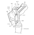
- FIG. 3 is an enlarged view showing one end of a tension band 2 in the occupant restraint device 100 according to the present invention
- 21 is a perspective view showing 21.
- a mounting portion 45 is provided at the upper end portion as described above.
- the mounting portion 45 has a gutter shape extending in the vertical direction, for example.
- through holes 452 are formed at the lower ends of both walls facing each other.
- the two through holes 452 are formed at positions consistent with each other.
- a fixing pin 451 for attaching one end 21 is inserted through the two through holes 452.
- the mounting portions 45 may be provided on the back side of the left and right long side frames 42 (frame body 4 of the seat back).
- the one end portion 21 of the tension band 2 has its tip folded back along the width direction thereof and sewn in two. As a result, a mounting loop 212 is formed at the tip of one end 21. After the fixing pin 451 is inserted through the one through hole 452, it is inserted into the other through hole 452 through the mounting loop 212, so that the one end portion 21 is attached to the mounting portion 45.
- the tip of the one end 21 is attached in this way and extends to the hook 41 via the upper open end of the attachment 45.
- the one end portion 21 is hooked on the hook portion 41, folded back, and extends to the airbag module 1.
- One end 21 has a twisted portion 211 in the middle.
- the twisted portion 211 is formed over a predetermined range in the longitudinal direction of one end portion 21.
- a first wide portion 213 is formed on the side of the mounting loop 212 with respect to the twisted portion 211, and a second wide portion 214 is formed on the opposite side.
- the first wide portion 213 and the second wide portion 214 are wider than the twisted portion 211, and are, for example, equal to the other end portion 22 of the tension band 2. That is, the twisted portion 211 is narrower than the other portions (first wide portion 213 and second wide portion 214).
- the twisted portion 211 is a portion whose width is narrowed by, for example, one end portion 21 being folded in half or sewn in three along the longitudinal direction.
- the twisted portion 211 is in a position where the width direction is twisted with respect to the other portion of the one end portion 21 (tension band 2).
- the twisted portion 211 has a different thickness direction from the other portion, and the thickness direction of the twisted portion 211 intersects with the thickness direction of the other portion. That is, the direction along the surface of the twisted portion 211 and the direction along the surface of the other portion intersect with each other.
- the direction along the surface of the twisted portion 211 and the direction along the surface of the other portion are orthogonal to each other (see FIG. 3).
- the occupant restraint device 100 further includes a hook portion 41.
- the hooking portions 41 are provided at both ends in the left-right direction in the short side frame 46 of the frame body 4 of the seat back.
- Each hooking portion 41 projects upward along the longitudinal direction of the long side frame 42.
- Each hook portion 41 has, for example, an L-shape in a vertical cross-sectional view, and is bent toward the center side of the frame body 4 of the seat back and the contact portion 411 that comes into surface contact with one end portion 21 (twisted portion 211). It has a detachment prevention unit 412. Therefore, it is possible to prevent the one end portion 21 hooked on the hook portion 41 from being separated from the hook portion 41.
- Each hook portion 41 is configured to be movable toward the center side of the frame body 4 of the seat back.
- the occupant restraint device 100 further includes a guide groove 43.
- the short side frame 46 is provided with a guide groove 43 for guiding each hook portion 41 to the center side of the frame body 4 of the seat back.
- the guide groove 43 extends from each end of the short side frame 46 to the intermediate portion of the short side frame 46 (center side of the frame body 4 of the seat back) along the longitudinal direction of the short side frame 46.
- the hook portion 41 slides in the guide groove 43 while the lower end portion of the contact portion 411 is engaged with the guide groove 43.
- the occupant restraint device 100 further includes an urging member 44 that urges the hooking portion 41 toward the center side of the frame body 4 of the seat back.
- the urging member 44 is formed by using, for example, a pretensioner or a retractor, and pulls the hooking portion 41 toward the center of the frame body 4 of the seat back.
- the urging member 44 instantly pulls the hook portion 41 toward the center of the frame 4 of the seat back at the same time as the expansion and deployment of the airbag 3 or immediately after the start of expansion and deployment.
- the urging member 44 instantly hooks the hooking portion 41 to the seat back frame 4 at the same time as the expansion and deployment of the airbag 3 or immediately after the start of expansion and deployment. Tow to the center side of. As a result, the hooking portion 41 moves to the center side of the frame body 4 of the seat back in a state where the one end portion 21 is hooked. Therefore, the position and the pulling direction of the tension band 2 can be changed so that the expanding and expanding airbag 3 can be brought closer to the center side of the frame body 4 of the seat back, that is, to the occupant side.
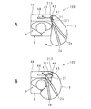
- FIG. 4 is an explanatory diagram illustrating the operation of the tension band 2 in the occupant restraint device 100 according to the present invention.
- FIG. 4 shows a state in which the occupant P is seated on the seat from above.
- FIG. 4A shows the initial stage of expansion and deployment of the airbag 3
- FIG. 4B shows the time when the expansion and deployment of the airbag 3 is completed.
- the airbag 3 is deployed at a position slightly distant from the occupant P.
- the front side of the occupant P is in an open state.
- the urging member 44 operates instantly to pull the hook portion 41.
- the hook portion 41 is pulled toward the center side of the frame body 4 of the seat back, and the two tension bands 2a and 2b are pulled toward the center side of the frame body 4 of the seat back. That is, the positions and orientations of the two tension bands 2a and 2b are changed in the direction of narrowing the distance between the occupant P and the two tension bands 2a and 2b.
- the airbag 3 is brought closer to the occupant P side, and a part of the airbag 3 is arranged on the front side of the occupant P. Therefore, the airbag 3 can surround the front side as well as the left side (right side) of the occupant P, and the occupant P is surely restrained by the airbag 3.
- FIG. 4 for convenience of explanation, a case where only the airbag 3 on the left side of the occupant P expands and expands is illustrated, but the present invention is not limited to this, and the air on the right side of the occupant P is not limited to this. Needless to say, the bag 3 also expands and expands at the same time.
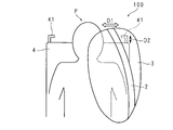
- FIG. 5 is a diagram showing the positional relationship between the expanding and deploying airbag 3 and the hooking portion 41 in the occupant restraint device 100 according to the present invention.
- the frame body 4 of the seat back and the occupant P are partially shown, the hook portion 41 is shown schematically, and the case where only the airbag 3 on the left side is expanded and deployed is shown. Further, in FIG. 5, only one of the two tension bands 2a and 2b is shown.
- the direction D1 (white arrow in FIG. 5) along the surface of the expanding and deploying airbag 3 is substantially orthogonal to the protruding direction D2 of the hooking portion 41. Therefore, when a conventional tension band is used, the tension band is twisted at the hook portion 41 when the hook portion 41 is moved, the tension band is entangled, and the surface contact with the hook portion 41 is not sufficient. There was a risk that the tension band could not be adjusted properly.
- one end 21 (tension band 2) has a twisted portion 211, and as described above, the twisted portion 211 has a twisted portion 211 with respect to the other portion. It is in a position where it can be twisted in the width direction. Therefore, in the tension band 2, the direction along the surface of the twisted portion 211 corresponds to the protruding direction D2 of the hooking portion 41, and the direction along the surface of the other portion (for example, the second wide portion 214) expands and expands. It corresponds to the direction D1 along the surface of the airbag 3.
- the width of the second wide portion 214 is widened, but only the width of the twisted portion 211 is narrowed. Therefore, the second wide portion 214 can surely bring the airbag 3 closer to the occupant P side, and the contact area between the twist portion 211 and the hook portion 41 (contact portion 411) can be reduced to reduce friction. It is possible to move the hooking portion 41 more quickly. Further, the size of the hooking portion 41 (contacting portion 411) in the protruding direction D2 can be reduced in accordance with the twisted portion 211, and the hooking portion 41 can be prevented from being damaged by the external force applied when the airbag 3 is expanded and deployed. ..
- a roller may be attached to the contact portion 411 of the hook portion 41, only the contact portion 411 may be configured to be rotatable, or the contact portion 411 may be configured to have a rotatable cylindrical shape. With such a configuration, the friction between the one end portion 21 and the hook portion 41 can be further reduced when the hook portion 41 is moved.
- FIG. 6 is an example view showing an example of one end 21 in the occupant restraint device 100 according to the second embodiment.
- the connecting portion between the twisted portion 211 and the second wide portion 214 is shown.
- the twisted portion 211 is connected to the second wide portion 214 so as to intersect the direction along the surface of the second wide portion 214.
- the twisted portion 211 is composed of, for example, two sheets, and has a strip shape. One end of the twisted portion 211 is sewn to the end of the second wide portion 214. Although not shown, the other end of the twisted portion 211 is also sewn to the end of the first wide portion 213 so that the direction along the surface intersects the direction along the surface of the first wide portion 213. ..
- the occupant restraint device 100 according to the second embodiment is also in a position where the twisted portion 211 is twisted in the width direction with respect to the other portion, as in the first embodiment. Therefore, in the tension band 2, the direction along the surface of the twisted portion 211 corresponds to the protruding direction D2 (see FIG. 5) of the hooking portion 41, and the direction along the surface of the other portion of the airbag 3 expands and expands. It corresponds to the direction D1 along the surface (see FIG. 5).
- the airbag 3 can be reliably brought closer to the occupant P side. Further, since the width of the twisted portion 211 is narrow, it is possible to prevent the one end portion 21 from being entangled when the hook portion 41 moves, and the surface contact between the hook portion 41 and the one end portion 21 (twisted portion 211). Can be secured, and the position and orientation of the tension band 2 can be adjusted more reliably. Further, the friction between the one end portion 21 and the hook portion 41 (contact portion 411) can be reduced, and the size of the hook portion 41 (contact portion 411) in the protruding direction D2 can be reduced.
- FIG. 7 is an example view showing an example of one end 21 of the occupant restraint device 100 according to the third embodiment.
- the connecting portion between the twisted portion 211 and the first wide portion 213 and the second wide portion 214 is shown.
- At least one end 21 of the tension band 2 is formed of one tubular member. That is, in the occupant restraint device 100 according to the third embodiment, the twisted portion 211, the first wide portion 213, and the second wide portion 214 have a two-piece configuration formed by flatly folding one tubular member. .. Therefore, the twisted portion 211, the first wide portion 213, and the second wide portion 214 are rectangular, and all have the same dimensions in the width direction.
- the twisted portion 211 is in a position where it is twisted in the width direction with respect to other portions. That is, the twisted portion 211 and the first wide portion 213 are provided so as to have different directions along their respective surfaces.
- the direction along the surface of the twisted portion 211 and the direction along the surface of the first wide portion 213 intersect (for example, orthogonally). Further, the direction along the surface of the twisted portion 211 and the direction along the surface of the second wide portion 214 intersect (for example, orthogonally).
- the thickness direction of the twisted portion 211 intersects with the thickness direction of the first wide portion 213 and the second wide portion 214, and the thickness direction of the first wide portion 213 and the thickness direction of the second wide portion 214 are It is parallel.
- seams are provided at least at one place along the respective width directions or intersecting the width directions so as to maintain these shapes. It may be formed.
- the occupant restraint device 100 also has the tension band 2 in the direction along the surface of the twisted portion 211 in the protruding direction D2 (see FIG. 5) of the hooking portion 41.
- the direction along the surface in the other portion corresponds to the direction D1 (see FIG. 5) along the surface of the expanding and deploying airbag 3.
- the hooking portion 41 moves, it is possible to prevent the one end portion 21 from being entangled, and the surface contact between the hooking portion 41 and the one end portion 21 (twisted portion 211) can be ensured, and the tension band 2 can be more reliably performed.
- the position and orientation of can be adjusted.
- the twisted portion 211, the first wide portion 213, and the second wide portion 214 are formed of one tubular material, and thus are manufactured. The process can be simplified and the configuration can be simplified.
- Airbag module 2 Tension band 3 Airbag 4 Seat back frame 21 One end 41 Hooking part 43 Guide groove 44 Biasing member 100
- Crew restraint device 211 Twisted part 213 1st wide part 214 2nd wide part
Landscapes
- Engineering & Computer Science (AREA)
- Mechanical Engineering (AREA)
- Air Bags (AREA)
Abstract
Description
図1は本発明に係る乗員拘束装置100がシートに取り付けられた場合を示す図である。図1においては、説明の便宜上、シートの表皮及び内側のクッション材を除いた、シートの枠体のみを図示している。
以下においては、前記シートに正常的に乗員が座った場合において、乗員の右肩付近をシートバックの枠体4の右側、乗員の左肩付近をシートバックの枠体4の左側と言い、乗員はシートバックの枠体4の前側に着座するとする。なお、シートバックの枠体4では上側にヘッドレスト7が設けられている。
なお、これに限定されるものでなく、左側の張力バンド2の他端部22の先端及び右側の張力バンド2の他端部22の先端に夫々ループを形成し、斯かるループを着座部の枠体8に設けたフックに引っ掛けることによって固定しても良い。
本実施の形態においては、取付部45が左右の長辺フレーム42の左右の表面に夫々設けられた場合について説明するが、これに限定されるものではない。例えば、左右の長辺フレーム42(シートバックの枠体4)の裏側に取付部45を設けても良い。
これにより、引掛部41がシートバックの枠体4の中心側に牽引され、2つの張力バンド2a,2bがシートバックの枠体4の中心側に向かって引っ張られる。即ち、乗員Pと2つの張力バンド2a,2bとの間隔を狭める方向に、2つの張力バンド2a,2bの位置及び向きが変更される。その結果、図4Bに示すように、エアバッグ3が乗員P側に寄せ付けられ、エアバッグ3の一部が乗員Pの前側に配置される。従って、エアバッグ3が乗員Pの左側(右側)と共に、前側も取り囲むことができ、乗員Pがエアバッグ3によって確実に拘束される。
よって、引掛部41が移動する際、一端部21が絡むことを未然に防止でき、引掛部41と一端部21との面接触を十分に確保でき、より確実に張力バンド2の位置及び向き(牽引方向)を調整できる。
また、捻じれ部211にあわせて、突出方向D2における引掛部41(接触部411)の寸法を減らすことができ、エアバッグ3の膨張展開時にかかる外力によって引掛部41が破損することを防止できる。
引掛部41の接触部411にローラーを取り付けてもよく、接触部411のみが回転可能に構成しても良く、接触部411を回転可能な円筒状に構成しても良い。このような構成によって、引掛部41の移動時に、一端部21と引掛部41との摩擦を更に減らすことができる。
実施の形態2に係る乗員拘束装置100では、張力バンド2の一端部21において、捻じれ部211と、第1広幅部213及び第2広幅部214とが夫々別部材からなる。
図7は、実施の形態3に係る乗員拘束装置100における一端部21の一例を示す例示図である。図7では、説明の便宜上、捻じれ部211と、第1広幅部213及び第2広幅部214との連結部について示している。
更に、実施の形態3に係る乗員拘束装置100においては、上述したように、捻じれ部211、第1広幅部213及び第2広幅部214が一つの筒状材かれ形成されているので、製造工程を簡略化でき、構成を簡素化できる。
2 張力バンド
3 エアバッグ
4 シートバックの枠体
21 一端部
41 引掛部
43 案内溝
44 付勢部材
100 乗員拘束装置
211 捻じれ部
213 第1広幅部
214 第2広幅部
Claims (6)
- シートバックの枠体に設けられたエアバッグを含む乗員拘束装置において、
膨張展開する前記エアバッグを、前記シートバックを有するシートに着席する乗員に向けて寄せ付けることができるバンドを備え、
前記バンドは、前記枠体の上部に設けられる一部分が、他部分に対して幅方向が捻じれる位置にある捻じれ部を有することを特徴とする乗員拘束装置。 - 前記シートバックは、前記バンドの前記一部分を引っ掛けており、且つ前記バンドの牽引方向を変更可能な引掛部を備え、
前記捻じれ部は、前記引掛部と接する部分に設けられることを特徴とする請求項1に記載の乗員拘束装置。 - 前記引掛部は、前記シートバックの枠体の上部に設けられ、前記枠体の中心側に移動可能に設けられることを備えることを特徴とする請求項2に記載の乗員拘束装置。
- 前記捻じれ部は、他部分よりも幅が狭いことを特徴とする請求項1から3の何れか一項に記載の乗員拘束装置。
- 前記一部分は一つの筒状材から形成されていることを特徴とする請求項1から3のいずれか1項に記載の乗員拘束装置。
- 前記捻じれ部では前記バンドが長手方向に沿って折られていることを特徴とする請求項4に記載の乗員拘束装置。
Priority Applications (5)
| Application Number | Priority Date | Filing Date | Title |
|---|---|---|---|
| US17/632,459 US12049184B2 (en) | 2019-08-07 | 2020-07-06 | Occupant restraint device |
| EP20849251.2A EP4011709A4 (en) | 2019-08-07 | 2020-07-06 | Occupant restraint device |
| JP2021537627A JP7217811B2 (ja) | 2019-08-07 | 2020-07-06 | 乗員拘束装置 |
| KR1020227007005A KR102638238B1 (ko) | 2019-08-07 | 2020-07-06 | 승차인 구속 장치 |
| CN202080052146.4A CN114126930B (zh) | 2019-08-07 | 2020-07-06 | 乘员约束装置 |
Applications Claiming Priority (2)
| Application Number | Priority Date | Filing Date | Title |
|---|---|---|---|
| JP2019145602 | 2019-08-07 | ||
| JP2019-145602 | 2019-08-07 |
Publications (1)
| Publication Number | Publication Date |
|---|---|
| WO2021024668A1 true WO2021024668A1 (ja) | 2021-02-11 |
Family
ID=74502940
Family Applications (1)
| Application Number | Title | Priority Date | Filing Date |
|---|---|---|---|
| PCT/JP2020/026375 Ceased WO2021024668A1 (ja) | 2019-08-07 | 2020-07-06 | 乗員拘束装置 |
Country Status (6)
| Country | Link |
|---|---|
| US (1) | US12049184B2 (ja) |
| EP (1) | EP4011709A4 (ja) |
| JP (1) | JP7217811B2 (ja) |
| KR (1) | KR102638238B1 (ja) |
| CN (1) | CN114126930B (ja) |
| WO (1) | WO2021024668A1 (ja) |
Cited By (1)
| Publication number | Priority date | Publication date | Assignee | Title |
|---|---|---|---|---|
| WO2023179981A1 (de) * | 2022-03-23 | 2023-09-28 | Autoliv Development Ab | Fangbandmechanismus für ein airbagmodul |
Families Citing this family (8)
| Publication number | Priority date | Publication date | Assignee | Title |
|---|---|---|---|---|
| CN114641414B (zh) * | 2019-12-04 | 2023-10-20 | 奥托立夫开发公司 | 乘员约束装置 |
| US12296775B2 (en) * | 2021-06-03 | 2025-05-13 | Hyundai Mobis Co., Ltd. | Seat airbag for vehicle |
| DE102022106752A1 (de) | 2022-03-23 | 2023-09-28 | Audi Aktiengesellschaft | Fahrzeugsitz |
| JP7544094B2 (ja) * | 2022-04-26 | 2024-09-03 | トヨタ自動車株式会社 | シート搭載型エアバッグ装置 |
| JP2024003651A (ja) * | 2022-06-27 | 2024-01-15 | 豊田合成株式会社 | 乗員保護装置 |
| KR20240058580A (ko) * | 2022-10-26 | 2024-05-03 | 현대모비스 주식회사 | 시트용 에어백 및 그 전개 제어방법 |
| CN222080582U (zh) * | 2024-02-06 | 2024-11-29 | 好孩子儿童用品有限公司 | 一种儿童安全座椅 |
| KR20260001949A (ko) * | 2024-06-28 | 2026-01-06 | 현대모비스 주식회사 | 에어백쿠션 및 에어백쿠션의 폴딩방법 |
Citations (3)
| Publication number | Priority date | Publication date | Assignee | Title |
|---|---|---|---|---|
| JP2014034356A (ja) | 2012-08-10 | 2014-02-24 | Toyota Motor Corp | 乗員保護装置 |
| JP2014051138A (ja) * | 2012-09-05 | 2014-03-20 | Toyota Motor Corp | 車両用安全装置 |
| WO2019107398A1 (ja) * | 2017-11-30 | 2019-06-06 | オートリブ ディベロップメント エービー | 乗員拘束装置 |
Family Cites Families (19)
| Publication number | Priority date | Publication date | Assignee | Title |
|---|---|---|---|---|
| US5570905A (en) * | 1995-03-28 | 1996-11-05 | Morton International, Inc. | Airbag tether attachment |
| US5636862A (en) * | 1995-09-07 | 1997-06-10 | General Motors Corporation | Air bag assembly with tether |
| EP0771694A2 (en) * | 1995-11-03 | 1997-05-07 | Morton International, Inc. | Airbag tether and attachment seam |
| US6874208B2 (en) * | 2001-03-14 | 2005-04-05 | Autoliv Asp, Inc. | Anchoring attachment apparatus |
| US6688641B2 (en) * | 2001-12-13 | 2004-02-10 | Autoliv Asp, Inc. | Compact tethering system and method for an inflatable curtain |
| US7192053B2 (en) * | 2003-09-12 | 2007-03-20 | General Motors Corporation | Automotive vehicle air bag system |
| US7621561B2 (en) * | 2006-03-07 | 2009-11-24 | Gm Global Technology Operations, Inc. | Simplified restraining tether system for use with a vehicle air bag system |
| US7712774B2 (en) * | 2006-11-06 | 2010-05-11 | Autoliv Asp, Inc. | Tension-based airbag mounting system |
| KR100990035B1 (ko) * | 2008-05-09 | 2010-10-26 | 아우토리브 디벨롭먼트 아베 | 테더 홀더를 구비한 차량용 조수석 에어백 쿠션 |
| KR100990030B1 (ko) * | 2008-05-09 | 2010-10-26 | 아우토리브 디벨롭먼트 아베 | 차량용 조수석 에어백 쿠션의 테더 꼬임 방지 구조 |
| WO2015168401A1 (en) * | 2014-05-01 | 2015-11-05 | Tk Holdings Inc. | Center side impact airbag module with control tether |
| US9994185B2 (en) * | 2016-08-23 | 2018-06-12 | Ford Global Technologies, Llc | Vehicle side air curtain with tether including a hole |
| DE102016010249A1 (de) * | 2016-08-26 | 2018-03-01 | Autoliv Development Ab | Airbagvorrichtung für ein Kraftfahrzeug, sowie Airbagkissen für eine Airbagvorrichtung |
| US10144385B2 (en) * | 2016-12-19 | 2018-12-04 | Ford Global Technologies, Llc | Side curtain including a strip connected to an inboard panel |
| KR102454012B1 (ko) * | 2017-09-22 | 2022-10-14 | 현대모비스 주식회사 | 사이드 에어백 장치 |
| WO2019107053A1 (ja) * | 2017-11-30 | 2019-06-06 | オートリブ ディベロップメント エービー | 乗員拘束装置 |
| EP3536563B1 (en) * | 2018-03-06 | 2021-04-28 | Autoliv Development AB | A vehicle seat |
| JP6691569B2 (ja) * | 2018-03-30 | 2020-04-28 | 株式会社Subaru | 車両の乗員保護装置 |
| KR102745653B1 (ko) * | 2019-10-29 | 2024-12-20 | 현대모비스 주식회사 | 차량의 사이드 에어백 |
-
2020
- 2020-07-06 US US17/632,459 patent/US12049184B2/en active Active
- 2020-07-06 CN CN202080052146.4A patent/CN114126930B/zh active Active
- 2020-07-06 WO PCT/JP2020/026375 patent/WO2021024668A1/ja not_active Ceased
- 2020-07-06 JP JP2021537627A patent/JP7217811B2/ja active Active
- 2020-07-06 EP EP20849251.2A patent/EP4011709A4/en active Pending
- 2020-07-06 KR KR1020227007005A patent/KR102638238B1/ko active Active
Patent Citations (4)
| Publication number | Priority date | Publication date | Assignee | Title |
|---|---|---|---|---|
| JP2014034356A (ja) | 2012-08-10 | 2014-02-24 | Toyota Motor Corp | 乗員保護装置 |
| JP2014051138A (ja) * | 2012-09-05 | 2014-03-20 | Toyota Motor Corp | 車両用安全装置 |
| WO2019107398A1 (ja) * | 2017-11-30 | 2019-06-06 | オートリブ ディベロップメント エービー | 乗員拘束装置 |
| WO2019107073A1 (ja) * | 2017-11-30 | 2019-06-06 | オートリブ ディベロップメント エービー | 乗員拘束装置 |
Non-Patent Citations (1)
| Title |
|---|
| See also references of EP4011709A4 |
Cited By (3)
| Publication number | Priority date | Publication date | Assignee | Title |
|---|---|---|---|---|
| WO2023179981A1 (de) * | 2022-03-23 | 2023-09-28 | Autoliv Development Ab | Fangbandmechanismus für ein airbagmodul |
| JP2025509833A (ja) * | 2022-03-23 | 2025-04-11 | オートリブ ディベロップメント エービー | エアバッグモジュールのためのテザー機構 |
| JP7806288B2 (ja) | 2022-03-23 | 2026-01-26 | オートリブ ディベロップメント エービー | エアバッグモジュールのためのテザー機構 |
Also Published As
| Publication number | Publication date |
|---|---|
| CN114126930A (zh) | 2022-03-01 |
| JPWO2021024668A1 (ja) | 2021-02-11 |
| US20220274555A1 (en) | 2022-09-01 |
| KR20220038168A (ko) | 2022-03-25 |
| EP4011709A1 (en) | 2022-06-15 |
| CN114126930B (zh) | 2023-04-28 |
| EP4011709A4 (en) | 2023-09-13 |
| KR102638238B1 (ko) | 2024-02-20 |
| JP7217811B2 (ja) | 2023-02-03 |
| US12049184B2 (en) | 2024-07-30 |
Similar Documents
| Publication | Publication Date | Title |
|---|---|---|
| JP7217811B2 (ja) | 乗員拘束装置 | |
| US7784828B2 (en) | Dual depth airbag with active venting | |
| KR102362655B1 (ko) | 사이드 에어백 장치 | |
| US11104287B2 (en) | Side air bag device | |
| JP2018176906A (ja) | 車両用サイドエアバッグ装置及びその製造方法 | |
| CN114641414B (zh) | 乘员约束装置 | |
| JP2008247241A (ja) | カーテンエアバッグ装置 | |
| JP4174515B2 (ja) | 車両用エアベルト装置 | |
| CN107284391A (zh) | 乘员保护装置 | |
| CN115768662A (zh) | 乘员约束装置 | |
| JP6873961B2 (ja) | 乗員拘束装置 | |
| CN112533798A (zh) | 侧面安全气囊装置 | |
| JP6175012B2 (ja) | シートベルト装置の製造方法 | |
| JP5337583B2 (ja) | エアバッグ装置 | |
| WO2014109162A1 (ja) | 助手席用エアバッグ及びそれを備えるエアバッグ装置、並びに車両構造 | |
| JP6499096B2 (ja) | 乗員保護装置 | |
| CN108725377B (zh) | 用于车辆的空气安全带装置 | |
| JP2017124759A (ja) | 乗員保護装置 | |
| JP5871475B2 (ja) | 乗員保護装置 | |
| JP4946444B2 (ja) | 乗員保護装置 | |
| JP2019034593A (ja) | エアベルト | |
| WO2022219983A1 (ja) | エアバッグ装置 | |
| JP2017114242A (ja) | サイドエアバッグ装置 | |
| JP6348850B2 (ja) | シートベルト装置及びシートベルト装置の製造方法 | |
| EP4368460A1 (en) | Airbag device |
Legal Events
| Date | Code | Title | Description |
|---|---|---|---|
| 121 | Ep: the epo has been informed by wipo that ep was designated in this application |
Ref document number: 20849251 Country of ref document: EP Kind code of ref document: A1 |
|
| ENP | Entry into the national phase |
Ref document number: 2021537627 Country of ref document: JP Kind code of ref document: A |
|
| NENP | Non-entry into the national phase |
Ref country code: DE |
|
| ENP | Entry into the national phase |
Ref document number: 20227007005 Country of ref document: KR Kind code of ref document: A |
|
| ENP | Entry into the national phase |
Ref document number: 2020849251 Country of ref document: EP Effective date: 20220307 |