WO2021024672A1 - ヒータ、およびステージ - Google Patents
ヒータ、およびステージ Download PDFInfo
- Publication number
- WO2021024672A1 WO2021024672A1 PCT/JP2020/026410 JP2020026410W WO2021024672A1 WO 2021024672 A1 WO2021024672 A1 WO 2021024672A1 JP 2020026410 W JP2020026410 W JP 2020026410W WO 2021024672 A1 WO2021024672 A1 WO 2021024672A1
- Authority
- WO
- WIPO (PCT)
- Prior art keywords
- heater
- insulating member
- sheath
- metal sheath
- hole
- Prior art date
- Legal status (The legal status is an assumption and is not a legal conclusion. Google has not performed a legal analysis and makes no representation as to the accuracy of the status listed.)
- Ceased
Links
Images







Classifications
-
- H—ELECTRICITY
- H05—ELECTRIC TECHNIQUES NOT OTHERWISE PROVIDED FOR
- H05B—ELECTRIC HEATING; ELECTRIC LIGHT SOURCES NOT OTHERWISE PROVIDED FOR; CIRCUIT ARRANGEMENTS FOR ELECTRIC LIGHT SOURCES, IN GENERAL
- H05B3/00—Ohmic-resistance heating
- H05B3/10—Heating elements characterised by the composition or nature of the materials or by the arrangement of the conductor
-
- H—ELECTRICITY
- H05—ELECTRIC TECHNIQUES NOT OTHERWISE PROVIDED FOR
- H05B—ELECTRIC HEATING; ELECTRIC LIGHT SOURCES NOT OTHERWISE PROVIDED FOR; CIRCUIT ARRANGEMENTS FOR ELECTRIC LIGHT SOURCES, IN GENERAL
- H05B3/00—Ohmic-resistance heating
- H05B3/40—Heating elements having the shape of rods or tubes
- H05B3/54—Heating elements having the shape of rods or tubes flexible
- H05B3/56—Heating cables
-
- H—ELECTRICITY
- H10—SEMICONDUCTOR DEVICES; ELECTRIC SOLID-STATE DEVICES NOT OTHERWISE PROVIDED FOR
- H10P—GENERIC PROCESSES OR APPARATUS FOR THE MANUFACTURE OR TREATMENT OF DEVICES COVERED BY CLASS H10
- H10P72/00—Handling or holding of wafers, substrates or devices during manufacture or treatment thereof
- H10P72/04—Apparatus for manufacture or treatment
- H10P72/0431—Apparatus for thermal treatment
- H10P72/0432—Apparatus for thermal treatment mainly by conduction
-
- H—ELECTRICITY
- H05—ELECTRIC TECHNIQUES NOT OTHERWISE PROVIDED FOR
- H05B—ELECTRIC HEATING; ELECTRIC LIGHT SOURCES NOT OTHERWISE PROVIDED FOR; CIRCUIT ARRANGEMENTS FOR ELECTRIC LIGHT SOURCES, IN GENERAL
- H05B3/00—Ohmic-resistance heating
- H05B3/40—Heating elements having the shape of rods or tubes
-
- C—CHEMISTRY; METALLURGY
- C23—COATING METALLIC MATERIAL; COATING MATERIAL WITH METALLIC MATERIAL; CHEMICAL SURFACE TREATMENT; DIFFUSION TREATMENT OF METALLIC MATERIAL; COATING BY VACUUM EVAPORATION, BY SPUTTERING, BY ION IMPLANTATION OR BY CHEMICAL VAPOUR DEPOSITION, IN GENERAL; INHIBITING CORROSION OF METALLIC MATERIAL OR INCRUSTATION IN GENERAL
- C23C—COATING METALLIC MATERIAL; COATING MATERIAL WITH METALLIC MATERIAL; SURFACE TREATMENT OF METALLIC MATERIAL BY DIFFUSION INTO THE SURFACE, BY CHEMICAL CONVERSION OR SUBSTITUTION; COATING BY VACUUM EVAPORATION, BY SPUTTERING, BY ION IMPLANTATION OR BY CHEMICAL VAPOUR DEPOSITION, IN GENERAL
- C23C14/00—Coating by vacuum evaporation, by sputtering or by ion implantation of the coating forming material
- C23C14/22—Coating by vacuum evaporation, by sputtering or by ion implantation of the coating forming material characterised by the process of coating
- C23C14/50—Substrate holders
-
- C—CHEMISTRY; METALLURGY
- C23—COATING METALLIC MATERIAL; COATING MATERIAL WITH METALLIC MATERIAL; CHEMICAL SURFACE TREATMENT; DIFFUSION TREATMENT OF METALLIC MATERIAL; COATING BY VACUUM EVAPORATION, BY SPUTTERING, BY ION IMPLANTATION OR BY CHEMICAL VAPOUR DEPOSITION, IN GENERAL; INHIBITING CORROSION OF METALLIC MATERIAL OR INCRUSTATION IN GENERAL
- C23C—COATING METALLIC MATERIAL; COATING MATERIAL WITH METALLIC MATERIAL; SURFACE TREATMENT OF METALLIC MATERIAL BY DIFFUSION INTO THE SURFACE, BY CHEMICAL CONVERSION OR SUBSTITUTION; COATING BY VACUUM EVAPORATION, BY SPUTTERING, BY ION IMPLANTATION OR BY CHEMICAL VAPOUR DEPOSITION, IN GENERAL
- C23C16/00—Chemical coating by decomposition of gaseous compounds, without leaving reaction products of surface material in the coating, i.e. chemical vapour deposition [CVD] processes
- C23C16/44—Chemical coating by decomposition of gaseous compounds, without leaving reaction products of surface material in the coating, i.e. chemical vapour deposition [CVD] processes characterised by the method of coating
- C23C16/458—Chemical coating by decomposition of gaseous compounds, without leaving reaction products of surface material in the coating, i.e. chemical vapour deposition [CVD] processes characterised by the method of coating characterised by the method used for supporting substrates in the reaction chamber
- C23C16/4582—Rigid and flat substrates, e.g. plates or discs
- C23C16/4583—Rigid and flat substrates, e.g. plates or discs the substrate being supported substantially horizontally
- C23C16/4586—Elements in the interior of the support, e.g. electrodes, heating or cooling devices
-
- C—CHEMISTRY; METALLURGY
- C23—COATING METALLIC MATERIAL; COATING MATERIAL WITH METALLIC MATERIAL; CHEMICAL SURFACE TREATMENT; DIFFUSION TREATMENT OF METALLIC MATERIAL; COATING BY VACUUM EVAPORATION, BY SPUTTERING, BY ION IMPLANTATION OR BY CHEMICAL VAPOUR DEPOSITION, IN GENERAL; INHIBITING CORROSION OF METALLIC MATERIAL OR INCRUSTATION IN GENERAL
- C23C—COATING METALLIC MATERIAL; COATING MATERIAL WITH METALLIC MATERIAL; SURFACE TREATMENT OF METALLIC MATERIAL BY DIFFUSION INTO THE SURFACE, BY CHEMICAL CONVERSION OR SUBSTITUTION; COATING BY VACUUM EVAPORATION, BY SPUTTERING, BY ION IMPLANTATION OR BY CHEMICAL VAPOUR DEPOSITION, IN GENERAL
- C23C16/00—Chemical coating by decomposition of gaseous compounds, without leaving reaction products of surface material in the coating, i.e. chemical vapour deposition [CVD] processes
- C23C16/44—Chemical coating by decomposition of gaseous compounds, without leaving reaction products of surface material in the coating, i.e. chemical vapour deposition [CVD] processes characterised by the method of coating
- C23C16/46—Chemical coating by decomposition of gaseous compounds, without leaving reaction products of surface material in the coating, i.e. chemical vapour deposition [CVD] processes characterised by the method of coating characterised by the method used for heating the substrate
-
- C—CHEMISTRY; METALLURGY
- C23—COATING METALLIC MATERIAL; COATING MATERIAL WITH METALLIC MATERIAL; CHEMICAL SURFACE TREATMENT; DIFFUSION TREATMENT OF METALLIC MATERIAL; COATING BY VACUUM EVAPORATION, BY SPUTTERING, BY ION IMPLANTATION OR BY CHEMICAL VAPOUR DEPOSITION, IN GENERAL; INHIBITING CORROSION OF METALLIC MATERIAL OR INCRUSTATION IN GENERAL
- C23C—COATING METALLIC MATERIAL; COATING MATERIAL WITH METALLIC MATERIAL; SURFACE TREATMENT OF METALLIC MATERIAL BY DIFFUSION INTO THE SURFACE, BY CHEMICAL CONVERSION OR SUBSTITUTION; COATING BY VACUUM EVAPORATION, BY SPUTTERING, BY ION IMPLANTATION OR BY CHEMICAL VAPOUR DEPOSITION, IN GENERAL
- C23C16/00—Chemical coating by decomposition of gaseous compounds, without leaving reaction products of surface material in the coating, i.e. chemical vapour deposition [CVD] processes
- C23C16/44—Chemical coating by decomposition of gaseous compounds, without leaving reaction products of surface material in the coating, i.e. chemical vapour deposition [CVD] processes characterised by the method of coating
- C23C16/50—Chemical coating by decomposition of gaseous compounds, without leaving reaction products of surface material in the coating, i.e. chemical vapour deposition [CVD] processes characterised by the method of coating using electric discharges
- C23C16/511—Chemical coating by decomposition of gaseous compounds, without leaving reaction products of surface material in the coating, i.e. chemical vapour deposition [CVD] processes characterised by the method of coating using electric discharges using microwave discharges
-
- H—ELECTRICITY
- H05—ELECTRIC TECHNIQUES NOT OTHERWISE PROVIDED FOR
- H05B—ELECTRIC HEATING; ELECTRIC LIGHT SOURCES NOT OTHERWISE PROVIDED FOR; CIRCUIT ARRANGEMENTS FOR ELECTRIC LIGHT SOURCES, IN GENERAL
- H05B1/00—Details of electric heating devices
- H05B1/02—Automatic switching arrangements specially adapted to apparatus ; Control of heating devices
- H05B1/0227—Applications
- H05B1/023—Industrial applications
- H05B1/0233—Industrial applications for semiconductors manufacturing
-
- H—ELECTRICITY
- H05—ELECTRIC TECHNIQUES NOT OTHERWISE PROVIDED FOR
- H05B—ELECTRIC HEATING; ELECTRIC LIGHT SOURCES NOT OTHERWISE PROVIDED FOR; CIRCUIT ARRANGEMENTS FOR ELECTRIC LIGHT SOURCES, IN GENERAL
- H05B3/00—Ohmic-resistance heating
- H05B3/02—Details
-
- H—ELECTRICITY
- H05—ELECTRIC TECHNIQUES NOT OTHERWISE PROVIDED FOR
- H05B—ELECTRIC HEATING; ELECTRIC LIGHT SOURCES NOT OTHERWISE PROVIDED FOR; CIRCUIT ARRANGEMENTS FOR ELECTRIC LIGHT SOURCES, IN GENERAL
- H05B3/00—Ohmic-resistance heating
- H05B3/02—Details
- H05B3/06—Heater elements structurally combined with coupling elements or holders
-
- H—ELECTRICITY
- H05—ELECTRIC TECHNIQUES NOT OTHERWISE PROVIDED FOR
- H05B—ELECTRIC HEATING; ELECTRIC LIGHT SOURCES NOT OTHERWISE PROVIDED FOR; CIRCUIT ARRANGEMENTS FOR ELECTRIC LIGHT SOURCES, IN GENERAL
- H05B3/00—Ohmic-resistance heating
- H05B3/10—Heating elements characterised by the composition or nature of the materials or by the arrangement of the conductor
- H05B3/18—Heating elements characterised by the composition or nature of the materials or by the arrangement of the conductor the conductor being embedded in an insulating material
-
- H—ELECTRICITY
- H05—ELECTRIC TECHNIQUES NOT OTHERWISE PROVIDED FOR
- H05B—ELECTRIC HEATING; ELECTRIC LIGHT SOURCES NOT OTHERWISE PROVIDED FOR; CIRCUIT ARRANGEMENTS FOR ELECTRIC LIGHT SOURCES, IN GENERAL
- H05B3/00—Ohmic-resistance heating
- H05B3/40—Heating elements having the shape of rods or tubes
- H05B3/42—Heating elements having the shape of rods or tubes non-flexible
- H05B3/48—Heating elements having the shape of rods or tubes non-flexible heating conductor embedded in insulating material
-
- H—ELECTRICITY
- H05—ELECTRIC TECHNIQUES NOT OTHERWISE PROVIDED FOR
- H05B—ELECTRIC HEATING; ELECTRIC LIGHT SOURCES NOT OTHERWISE PROVIDED FOR; CIRCUIT ARRANGEMENTS FOR ELECTRIC LIGHT SOURCES, IN GENERAL
- H05B3/00—Ohmic-resistance heating
- H05B3/62—Heating elements specially adapted for furnaces
- H05B3/64—Heating elements specially adapted for furnaces using ribbon, rod, or wire heater
-
- H—ELECTRICITY
- H05—ELECTRIC TECHNIQUES NOT OTHERWISE PROVIDED FOR
- H05B—ELECTRIC HEATING; ELECTRIC LIGHT SOURCES NOT OTHERWISE PROVIDED FOR; CIRCUIT ARRANGEMENTS FOR ELECTRIC LIGHT SOURCES, IN GENERAL
- H05B3/00—Ohmic-resistance heating
- H05B3/68—Heating arrangements specially adapted for cooking plates or analogous hot-plates
-
- H—ELECTRICITY
- H05—ELECTRIC TECHNIQUES NOT OTHERWISE PROVIDED FOR
- H05B—ELECTRIC HEATING; ELECTRIC LIGHT SOURCES NOT OTHERWISE PROVIDED FOR; CIRCUIT ARRANGEMENTS FOR ELECTRIC LIGHT SOURCES, IN GENERAL
- H05B6/00—Heating by electric, magnetic or electromagnetic fields
- H05B6/64—Heating using microwaves
- H05B6/647—Aspects related to microwave heating combined with other heating techniques
-
- H—ELECTRICITY
- H10—SEMICONDUCTOR DEVICES; ELECTRIC SOLID-STATE DEVICES NOT OTHERWISE PROVIDED FOR
- H10P—GENERIC PROCESSES OR APPARATUS FOR THE MANUFACTURE OR TREATMENT OF DEVICES COVERED BY CLASS H10
- H10P50/00—Etching of wafers, substrates or parts of devices
- H10P50/20—Dry etching; Plasma etching; Reactive-ion etching
- H10P50/24—Dry etching; Plasma etching; Reactive-ion etching of semiconductor materials
- H10P50/242—Dry etching; Plasma etching; Reactive-ion etching of semiconductor materials of Group IV materials
-
- H—ELECTRICITY
- H10—SEMICONDUCTOR DEVICES; ELECTRIC SOLID-STATE DEVICES NOT OTHERWISE PROVIDED FOR
- H10P—GENERIC PROCESSES OR APPARATUS FOR THE MANUFACTURE OR TREATMENT OF DEVICES COVERED BY CLASS H10
- H10P72/00—Handling or holding of wafers, substrates or devices during manufacture or treatment thereof
- H10P72/04—Apparatus for manufacture or treatment
- H10P72/0431—Apparatus for thermal treatment
Definitions
- An embodiment of the present invention relates to a heater and a stage provided with a heater.
- the semiconductor device is a device that utilizes the semiconductor characteristics of silicon and the like.
- a semiconductor device is composed of a semiconductor film, an insulating film, and a conductive film laminated on a substrate, and these films are patterned. These films are laminated using a thin film deposition method, a sputtering method, a chemical vapor deposition (CVD) method, a chemical reaction of a substrate, or the like, and these films are patterned by a photolithography process.
- the photolithography process includes forming a resist film on a film to be subjected to patterning, exposing the resist film, forming a resist mask by development, partially removing the film by etching, and removing the resist mask.
- the characteristics of the film described above are greatly affected by the conditions for forming the film or the conditions for patterning.
- One of the above conditions is the temperature of the substrate.
- the temperature of the substrate is controlled by adjusting the temperature of the mounting table (hereinafter referred to as a stage) for mounting the substrate.
- One of the heaters that heat the stage is a sheath heater in order to heat the substrate and uniformly suppress the temperature distribution in the substrate.
- Patent Document 1 discloses a stage provided with a plurality of sheath heaters in which heating wires (heater wires) are arranged in a metal sheath.
- a stage equipped with a high density of heaters is required. Further, in order to provide the heater on the stage at a high density, it is an issue to reduce the diameter of the heater. Further, as the diameter of the heater is reduced, it is an issue to improve the reliability of the heater with a reduced diameter so that the heater is not damaged or the heating wire in the heater is not broken.
- one of the problems of the embodiment of the present invention is to provide a sheath heater having improved reliability and a reduced diameter.
- Another object of the present invention is to provide a stage provided with a heater for precisely controlling the temperature of the substrate.
- One of the embodiments of the present invention is a heater, which is a folded heater wire, a first insulator provided on the heater wire, and a metal provided so as to be in contact with at least a part of the first insulator.
- Sheath metal A first insulating member arranged parallel to at least one part of a heater wire taken out from the first end of the sheath, a metal arranged parallel to at least a part of the first insulating member.
- It covers a part of the second insulating member and the first insulating member which are in contact with each other, and is in contact with at least a part of the metal sheath, the first insulating member and the second insulating member through the second insulating member. It has a metal sheath, a first insulating member and a lid-like member arranged parallel to at least a part of the second insulating member.
- the lid-like member may be composed of one member having a recess and having a predetermined thickness.
- the inner diameter of the lid-shaped member may be substantially the same as the outer diameter of the first insulating member, and the outer diameter of the lid-shaped member may be substantially the same as the outer diameter of the metal sheath.
- the inner diameter of the metal sheath and the outer diameter of the first insulating member are substantially the same, and the first insulating member may be inserted through the metal sheath.
- the first insulating member may have a protrusion and the lid-like member may fit into the protrusion via the second insulator.
- the protrusion may protrude in the direction opposite to the direction in which the metal sheath is provided.
- the first insulating member may have a through hole and the second insulating member may be inserted through the through hole.
- the hole diameter of the through hole may be different between the upper part and the lower part of the first insulating member.
- the cross section of the through hole is stepped at connecting portions having different hole diameters, and the second insulating member may be inserted to the connecting portion.
- the heater wire may be strip-shaped.
- the heater wire may have a spiral structure.
- the heater wire may have a double helix structure.
- the insulator of 2 may be a sealant or an adhesive.
- the metal sheath may contain aluminum.
- the outer diameter of the metal sheath may be 3.0 mm or more and 6.0 mm or less.
- the lid-like member may contain aluminum.
- the outer diameter of the lid-shaped member may be 3.0 mm or more and 6.0 mm or less.
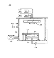
- FIG. 6 is a schematic cross-sectional view of a film processing apparatus including a stage according to an embodiment of the present invention.
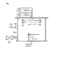
- FIG. 6 is a schematic cross-sectional view of a film forming apparatus including a stage according to an embodiment of the present invention.
- FIG. 6 is a schematic cross-sectional view of a film forming apparatus including a stage according to an embodiment of the present invention.
- FIG. 6 is a schematic cross-sectional view of a film forming apparatus including a stage according to an embodiment of the present invention.
- FIG. 6 is a schematic cross-sectional view of a film forming apparatus including a stage according to an embodiment of the present invention.
- FIGS. 1A to 1F Configuration of Sheath Heater
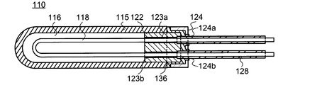
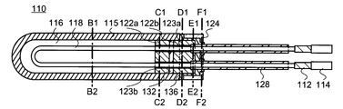
- FIG. 1A is a cross-sectional view showing the configuration of the sheath heater 110.
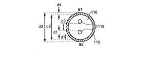
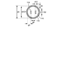
- FIG. 1B is a cross-sectional view showing a configuration along chain lines B1 and B2.
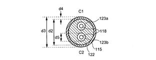
- FIG. 1C is a cross-sectional view showing a configuration along chain lines C1 and C2.
- FIG. 1D is a cross-sectional view showing a configuration along chain lines D1 and D2.
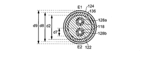
- FIG. 1E is a cross-sectional view showing a configuration along chain lines E1 and E2.
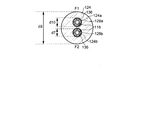
- FIG. 1F is a cross-sectional view showing a configuration along chain lines F1 and F2.
- the sheath heater 110 has a function of generating heat when energized.
- the sheath heater 110 is provided to heat the second support plate 104 (see FIG. 6A) and the first support plate 102 (see FIG. 6A) of the stage 100 (see FIG. 6A). As a result, the substrate installed on the stage 100 can be heated.
- the sheath heater 110 includes a metal sheath 115, a heater wire 118, a first insulator 116, a second insulator 136, a first insulating member 122, a lid-like member 124, and a second insulating member. Includes 128, a pair of lead wires 112, and a pair of terminals 114.
- FIG. 1A a so-called single-terminal type sheath heater 110 is illustrated.
- the configuration of the sheath heater 110 according to the embodiment of the present invention will be described by taking the single-terminal type sheath heater 110 as an example, but the same configuration as the sheath heater 110 according to the embodiment of the present invention will be described. It may be applied to a double-terminal type sheath heater.
- the right side is referred to as an upper portion and the left side is referred to as a lower portion.
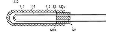
- the metal sheath 115 has a cylindrical shape in which the first end (closed end) is closed and the second end (open end) is open.
- the shape of the tip of the metal sheath 115 shows an example of a semicircular shape, but the shape is not limited to this example.
- the shape of the tip of the metal sheath 115 may be a planar shape or a conical shape. The shape may be such that the second support plate 104 (see FIG. 6A) and the first support plate 102 (see FIG. 6A), which will be described later, can be heated by the heat generated by the sheath heater 110.
- the heater wire 118 is folded in the metal sheath 115, arranged so as to reciprocate in the cylindrical axis direction of the metal sheath 115, and both ends thereof are taken out from the second end (open end) of the metal sheath 115. That is, one heater wire 118 is arranged so as to have two axes (two cores) in most of the metal sheath 115 in the cylindrical axis direction, one of the two axes and one terminal, and the other and the other of the two axes. Is taken out from the second end (open end) of the metal sheath 115.
- one of the two axes of one heater wire 118 and the other of the two axes are arranged so as to be substantially parallel or parallel to the cylindrical axis direction of the metal sheath 115. Even if at least one part of the two axes of one heater wire 118 and at least a part of the other of the two axes are arranged so as to be substantially parallel or parallel to the cylindrical axis direction of the metal sheath 115. Good. Further, the heater wire 118 is arranged in the metal sheath 115 with a gap.
- the heater wire 118 includes a heating wire and a non-heating wire.
- the heater wire 118 and the metal sheath 115 are insulated by a first insulator 116 provided in the gap. That is, the heater wire 118 is surrounded by the first insulator 116, and the first insulator 116 is surrounded by the metal sheath 115. Further, the first insulator 116 is between the second end (open end) and the first end (closed end) of the metal sheath 115, up to the vicinity of the second end (open end). It is provided so as to fill the inside of the metal sheath 115 of the above.
- the first insulator 116 may be provided so as to be in contact with at least a part of the metal sheath 115, may be provided so as to be in contact with at least a part of the heater wire 118, or may be in contact with the metal sheath 115. It may be provided so as to insulate the heater wire 118 and the metal sheath 115, or it may be provided so as to insulate the heater wire 118 and the metal sheath 115 without contacting the heater wire 118. That is, the first insulator 116 may be provided so as to insulate the heater wire 118 and the metal sheath 115.
- a first insulating member 122 is provided on the upper part of the first insulating body 116.
- the first insulating member 122 is provided so as to be in contact with the upper portion of the first insulator 116 and at least a part of the inside of the metal sheath 115 and project from the upper portion of the metal sheath 115.
- the first insulating member 122 has at least a first through hole 123a and a second through hole 123b.
- One of both ends of the heater wire 118 taken out from the second end (open end) of the metal sheath 115 is inserted into the first through hole 123a, and the other is inserted into the second through hole 123b.
- both ends of the heater wire 118 are inserted into the first insulating member 122 from the side where the first insulator 116 is arranged, and are taken out from the side where the first insulator 116 is not arranged. ..
- at least a part of the first through hole 123a and at least a part of the second through hole 123b may be provided substantially parallel or parallel to the cylindrical axis of the metal sheath 115.
- at least a part of the heater wire 118 inserted through the first through hole 123a and the second through hole 123b may be provided substantially parallel or parallel to the cylindrical axis of the metal sheath 115.
- first through hole 123a and at least a part of the second through hole 123b are at least one of the heater wires 118 inserted through the first through hole 123a and the second through hole 123b. It may be provided substantially parallel or parallel to the portion.
- the first insulating member 122 is sometimes called a protective tube, an insulating tube, or the like.
- the hole diameter on the upper side of the first insulating member 122 and the hole diameter on the lower side of the first insulating member 122 are different.
- the hole diameter on the upper side of the first insulating member 122 is larger than the hole diameter on the lower side of the first insulating member 122. That is, the first through hole 123a and the second through hole 123b have a hole diameter on the lower side of the first insulating member 122 from the side in contact with the first insulator 116 of the first insulating member 122 to a predetermined length.
- the first through hole 123a and the second through hole 123b have a stepped shape.
- the hole diameter on the upper side of the first insulating member 122 is larger than the hole diameter on the lower side of the first insulating member 122, so that the first through hole 123a Is a stopper that stops the second insulating member 128, which will be described later, at the stepped portion.
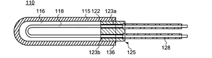
- one of the two second insulating members 128 is inserted into the first through hole 123a and is provided so as to be in contact with the stepped portion of the first through hole 123a.
- the other of the two second insulating members 128 is inserted into the second through hole 123b and is provided so as to be in contact with the stepped portion.
- the second insulating member 128 has a through hole. One of both ends of the heater wire 118 taken out from the first through hole of the first insulating member 122 is inserted into one of the two second insulating members 128, and the first penetration of the first insulating member 122 is performed.
- the two second insulating members 128 may be provided substantially parallel or parallel to the cylindrical axis of the metal sheath 115, and a part of the two second insulating members 128 is a cylinder of the metal sheath 115. It may be provided substantially parallel or parallel to the axis.
- the heater wire 118 inserted through the two second insulating members 128 may also be provided substantially parallel to the cylindrical shaft of the metal sheath 115, and a part of the heater wire 118 is a cylindrical shaft of the metal sheath 115. It may be provided substantially parallel to or parallel to.
- the outer diameter of the second insulating member 128 is smaller than the outer diameter of the first insulating member 122, and the hole diameter of the upper portion of the first through hole 123a and the second through hole of the first insulating member 122 have. It is preferable that the hole diameter is equivalent to that of 123b.
- the length of the second insulating member 128 is a length that protrudes from the position where the lid-shaped member 124 is provided.
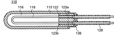
- the second insulator 136 is provided so as to be in contact with a part of the metal sheath 115, a part of the first insulating member 122, a part of the inside of the lid-shaped member 124, and a part of the second insulating member 128. Be done. A portion of the metal sheath 115, a portion of the first insulating member 122, a portion of the inside of the lid-like member 124, and a second insulating member 128 are connected by the second insulator 136.
- the second insulator 136 may be provided so as to protrude from the lid-shaped member 124 on the side opposite to the side connecting the lid-shaped member 124 and the metal sheath 115.
- the second insulator 136 is sometimes called a sealant, an adhesive, or the like.
- the second insulator 136 prevents the intrusion of moisture such as moisture and solvent into the sheath heater 110, and suppresses expansion and deterioration of the first insulator 116.
- the lid-shaped member 124 is connected to a part of the metal sheath 115, a part of the first insulating member 122, and the second insulating member 128 via the second insulating member 136.
- the lid-like member 124 has an inwardly recessed structure.
- the recessed portion of the lid-like member 124 has at least two holes.
- the recessed portion of the lid-like member 124 has two holes, and the two holes are the first hole 124a and the second hole 124b.
- One of the two second insulating members 128 is inserted into the first hole 124a, and the other of the two second insulating members 128 is inserted into the second hole 124b.
- the hole diameters of the first hole 124a and the second hole 124b are larger than the outer diameter of the second insulating member 128, and the hole diameter of the upper part of the first through hole 123a and the first through hole 123a of the first insulating member 122. It is preferable that the diameter is the same as that of the through hole 123b of 2.
- the lid-shaped member 124 is arranged in parallel with at least a part of the metal sheath 115, the first insulating member 122, and the second insulating member 128.
- the lid-shaped member 124 has a recessed portion and is composed of one member having a predetermined thickness, so that the outer diameter of the lid-shaped member 124 is the same as the outer diameter of the metal sheath 115. , Or can have approximately the same diameter. Therefore, the sheath heater 110 according to the embodiment of the present invention can have a uniform or substantially uniform outer diameter (thickness) by approximately matching the thicknesses of two or more members.
- a pair of lead wires 112 are connected to both ends of the heater wire 118.
- a pair of terminals 114 are connected to the lead wire 112.
- a pair of terminals 114 may be connected to both ends of the heater wire 118 without using the lead wire 112.
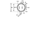
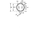
- the outer diameter of the heater wire 118 is d1
- the inner and outer diameters of the metal sheath 115 are d2 and d3, respectively, and the thickness of the metal sheath 115.
- d4 the diameter of the first through hole 123a and the second through hole 123b is d5
- the diameter of the second insulator 136 in the cross section of the configuration along the chain wires D1 and D2 is d6, the second insulating member 128a and the second.
- the outer diameter of the insulating member 128b of 2 is d7
- the diameter of the second insulator 136 in the cross section of the configuration along the chain wires E1 and E2 is d8
- the outer diameter of the lid-shaped member 124 is d9
- the outer diameter of the lid-shaped member 124 is along the chain wires F1 and F2.
- the diameter of the second insulator 136 in the cross section of the configuration is d10
- the distance between the heater wires 118 is g1
- the distance between the outer wall of the heater wire 118 and the inner wall of the metal sheath 115 is g2.
- the outer diameter of the first insulating member 122 is also d2.
- the outer diameter d3 of the metal sheath 115, the diameter d6 of the second insulator 136 in the cross section of the configuration along the chain wires D1 and D2, and the outer diameter d9 of the lid-shaped member 124 are the same diameter or substantially the same diameter.
- the diameter d8 of the second insulator 136 in the cross section of the configuration along the chain lines E1 and E2 is also the inner diameter of the lid-shaped member 124.
- the predetermined thickness of the lid-shaped member 124 is (d9-d8) / 2, and the predetermined thickness (d9-d8) / 2 of the lid-shaped member 124 is thinner than the thickness of the metal sheath 115.
- the outer diameter d1 of the heater wire 118 can be selected from the range of 0.1 mm or more and 2.0 mm or less.
- the inner diameter d2 of the metal sheath 115 can be selected from the range of 3.0 mm or more and 4.0 mm or less, and the outer diameter d3 of the metal sheath 115 can be selected from the range of 3.0 mm or more and 6.0 mm or less.
- the thickness d4 of the metal sheath 115 can be selected from the range of 0.5 mm or more and 1.0 mm or less.
- the distance g1 between the metal sheath 115 and each heater wire 118 arranged in the metal sheath 115 can be selected from the range of 0.3 mm or more and 1.0 mm or less, or 0.4 mm or more and 1.0 mm or less.
- the distance g2 between the folded portion from one end of the heater wire 118 and the folded portion from the other end is selected from the range of 0.3 mm or more and 2.0 mm or less, or 0.4 mm or more and 1.0 mm or less.
- the outer diameter d7 of the second insulating member 128a and the second insulating member 128b can be selected from the range of 1.0 mm or more and 4.5 mm or less.
- a conductor that generates Joule heat when energized can be used for the heater wire 118.
- a metal selected from tungsten, tantalum, molybdenum, platinum, nickel, chromium, and cobalt, or an alloy containing these metals can be used.
- the alloy include an alloy of nickel and chromium, an alloy containing nickel, chromium, and cobalt.
- the first insulator 116 is provided to prevent the heater wire 118 from coming into contact with the metal sheath 115 and short-circuiting.
- the material used for the first insulator 116 can be selected from insulating materials having a thermal conductivity of 10 W / mK or more and 200 W / mK. By using such a material, the thermal energy generated by the heater wire 118 can be efficiently transferred to the metal sheath 115.
- Examples of the first insulator 116 include magnesium oxide, aluminum oxide, boron nitride, and aluminum nitride.
- the metal sheath 115 contains a metal, and the metal can be selected from metals having a thermal conductivity of 10 W / mK or more and 430 W / mK or less. By selecting such a metal, the thermal energy generated by the heater wire 118 can be efficiently transferred to the first support plate 102 and the second support plate 104.
- the metal preferably has a coefficient of thermal expansion of 5 ⁇ 10 -6 / K or more and 25 ⁇ 10 -6 / K or less. As a result, deformation due to thermal expansion can be suppressed, and a highly reliable sheath heater 110 can be provided.
- a metal or alloy such as aluminum, titanium, or stainless steel can be used for the metal sheath 115.
- a fluorine-based adhesive for example, a fluorine-based adhesive, an epoxy-based adhesive, a silicone-based adhesive, or the like can be used.
- the first insulating member 122 is formed of a material containing aluminum oxide, zirconium oxide, magnesium oxide, aluminum nitride, silicon oxide and the like.
- lid-shaped member 124 a member having the same material and the same characteristics as the metal sheath 115 can be used.
- the second insulating member 1208 for example, an insulating tube formed of vinyl chloride, silicon rubber, a fluoropolymer, polyimide, glass fiber, ceramic fiber woven fabric, or the like can be used.
- the sheath heater 110 there are no restrictions on the shape of the cross section of the sheath heater 110 perpendicular to the cylindrical axis, and the sheath heater 110 having various structures can be used.
- it may be circular as shown in FIG. 1B, polygonal as the grooves shown in FIGS. 7B and 8B described later, and may be elliptical, although not shown.
- the cross-sectional shape is circular, the force required for deformation does not depend on the bending direction, so that the sheath heater 110 can be easily bent in any direction. Therefore, the sheath heater 110 can be easily arranged in the groove formed in the first support plate 102 or the second support plate 104 that is vertically longitudinally rearward.
- a sheath heater for example, in a pair of heater wires taken out from the open end of a metal sheath, one heater wire and the other heater wire are separated from each other, and an insulating tube is maintained so as to maintain the distance. It had a structure in which an insulating member such as the above was attached, a lead wire was connected to each of one heater wire and the other heater wire, and the pair of lead wires were bundled by an insulating member such as an insulating tube. At least part of such a structure is called a fastening.
- the conventional sheath heater has a structure in which the above structure is inserted into, for example, a two-step stepped tubular member, and the two-step stepped tubular member and the metal sheath are connected by brazing. Had had. Therefore, the conventional sheath heater is a heater having a complicated structure and a large diameter by at least a fastening portion and a stepped tubular member.
- the sheath heater according to the embodiment of the present invention does not include the fastening portion and the stepped tubular member that the conventional sheath heater has.
- the pair of heater wires 118 taken out from the open end of the metal sheath 115 is the outer diameter of the first insulating member 122 and the metal sheath 115, which are smaller than the outer diameter of the metal sheath 115.
- the metal sheath 115 Surrounded by a second insulating member 128 that is smaller in diameter, the metal sheath 115 has an outer diameter equivalent to the outer diameter of the metal sheath 115 by the second insulator 136, and the second insulating member 128 is inserted through the metal sheath 115. It has a structure connected to the lid-shaped member 124.
- the lid-shaped member 124 is composed of one member having a recessed portion and having a predetermined thickness, whereby the outer diameter of the lid-shaped member 124 is formed. Can have the same diameter as the outer diameter of the metal sheath 115, or substantially the same diameter. Therefore, the sheath heater 110 according to the embodiment of the present invention does not include the fastening portion and the stepped tubular member that the conventional sheath heater has, and by roughly matching the thicknesses of two or more members. The outer diameter (thickness) can be uniform or substantially uniform. Therefore, the sheath heater 110 can be formed thin. Further, by using the thin sheath heater 110, the sheath heater 110 can be laid out at a high density on the stage 100 described later. Therefore, the temperature distribution on the substrate can be made uniform, and the temperature distribution on the substrate can be further reduced.
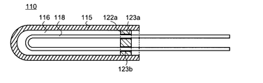
- FIGS. 2A to 2D are cross-sectional views showing a manufacturing method of the sheath heater 110.
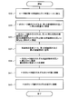
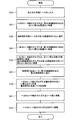
- FIG. 3 is a diagram showing a flowchart for explaining a method of manufacturing the sheath heater 110.
- the right side is referred to as an upper portion and the left side is referred to as a lower portion. Description of the same or similar configurations as those in FIGS. 1A to 1F may be omitted.
- the heater wire 118 folded in the metal sheath 115 is attached to the metal sheath 115 together with the first insulator 116. Insert in. Both ends of the heater wire 118 are taken out from one end of the metal sheath 115. The length of the pair of heater wires 118 taken out from one end of the metal sheath 115 is sufficiently longer than the length of the metal sheath 115.
- both ends of the heater wire 118 taken out from one end of the metal sheath 115 are inserted into the first insulating member 122.
- one of both ends of the heater wire 118 is inserted into the first through hole 123a included in the first insulating member 122, and the other end of the heater wire 118 is inserted into the first through hole 123a. It is inserted into the second through hole 123b included in the insulating member 122.
- the first insulating member 122 through which both ends of the heater wire 118 are inserted is fitted into the metal sheath 115 surrounding the first insulator 116 and the heater wire 118.
- the first insulating member 122 Since the outer diameter of the metal sheath 115 and the outer diameter of the first insulating member 122 are substantially the same or the same diameter, the first insulating member 122 is fixed to the metal sheath 115 surrounding the heater wire 118 by step 33. can do.
- the first insulating member 122 uses a ceramic-based insulating tube having two through holes. At this time, the length of the protruding portion 125 of the first insulating member 122 protruding from the metal sheath 115 may be measured. By measuring the length of the protrusion 125, it can be confirmed whether or not the heater wire 118 is inserted into the first insulating member 122 and the first insulating member 122 is properly provided on the metal sheath 115. Good.
- one of both ends of the heater wire 118 is inserted into the second insulating member 128a, and the other end of the heater wire 118 is inserted. It is inserted through the second insulating member 128b.
- the second insulating member 128a is inserted into the upper hole of the first through hole 123a and stops at the stepped portion.
- the second insulating member 128b is inserted into the upper hole of the second through hole 123b and stops at the stepped portion.
- the outer diameter of the second insulating member 128 and the hole diameter of the first through hole 123 are substantially the same or the same diameter, and by step 35, the second insulating member 128 has a stepped shape of the first through hole 123. Since it stops at the portion, the second insulating member 128a and the second insulating member 128b can be fixed to the first insulating member 122. Therefore, the second insulating member 128 is misaligned, and moisture such as moisture and solvent can be prevented from entering the sheath heater 110 through the gap between the second insulating member 128 and the first insulating member 122. .. Therefore, the deterioration of the sheath heater 110 is suppressed, and the long-term reliability of the sheath heater 110 is improved.
- the second insulating member 128 uses an insulating tube formed of polyimide. Further, as the second insulating member 128, an insulating tube having an outer diameter d7 of about 2 mm was used.
- the second insulator 136 is applied to the metal sheath 115, the first insulating member 122, and the second insulating member 128.
- the second insulator 136 uses a fluorine-based adhesive.
- the second insulator 136 is in contact with a part of the metal sheath 115, a part of the first insulating member 122, and a part of the second insulating member 128.
- the second insulating body 136 is provided so as to cover the protruding portion 125 of the first insulating member 122 and surround the protruding portion of the first insulating member 122.
- FIG. 2C is a schematic cross-sectional view of the sheath heater 110, and the second insulator 136 actually has a curved shape including an inflection point.
- the lid-shaped member 124 is attached to a part of the metal sheath 115 and a part of the first insulating member 122 by the second insulator 136. And a part of the second insulating member 128.
- One of the two second insulating members 128 is inserted into the first hole 124a of the lid-shaped member 124, and the other of the two second insulating members 128 is inserted into the second hole 124b of the lid-shaped member 124. Will be done.
- the lid-shaped member 124 Since the lid-shaped member 124 has an inwardly recessed structure, the lid-shaped member 124 is a part of the metal sheath 115 and a part of the first insulating member 122 so as to cover the protruding portion 125 of the first insulating member 122. , And a part of the second insulating member 128.
- the lid-like member 124 becomes a state in which the metal sheath 115 is covered with the first insulating member 122, and is fixed to the metal sheath 115 and the first insulating member 122.
- the outer diameter of the metal sheath 115 and the outer diameter of the first insulating member 122 are substantially the same or the same diameter, and the inner diameter of the lid-shaped member 124 and the outer diameter of the first insulating member 122 are substantially the same. Alternatively, since the diameters are the same, the lid-shaped member 124 can be fitted without being displaced with respect to the first insulating member 122.
- step 41 (S41) of FIGS. 1A and 3 a pair of lead wires 112 are connected to both ends of the heater wire 118.
- steps 43 (S43) of FIGS. 1A and 3 the pair of terminals 114 are connected to the pair of lead wires 112.
- the sheath heater 110 is manufactured by the manufacturing method described above.
- the method for manufacturing the sheath heater 110 described with reference to FIGS. 1A, 2 to 2D, and FIG. 3 is an example, and is not limited to this example.
- As a method for producing the sheath heater 110 an appropriately selected method may be used as long as the configuration of the sheath heater 110 according to the embodiment of the present invention is not deviated.
- the brazing step is omitted in the method for manufacturing the sheath heater 110 according to the embodiment of the present invention.
- a method of connecting the metal sheath 115 and the lid-like member 124 with a second insulator 136 (adhesive) can be used. Therefore, the method for manufacturing the sheath heater 110 according to the embodiment of the present invention is relatively easy and has high safety as compared with the conventional manufacturing method.
- the metal sheath 115 and the lid-shaped member 124 are connected by a second insulator 136.
- the second insulator 136 is an adhesive or a sealing agent and contains an organic resin. Therefore, even if a force for bending the sheath heater 110 is applied to the sheath heater 110, the second insulator 136 functions as a soft cushioning material and can alleviate the bending force. Therefore, in the sheath heater according to the embodiment of the present invention, the metal sheath 115 and the lid-shaped member 124 are connected by the second insulator 136, so that the diameter-reduced sheath heater 110 is damaged or reduced in diameter. It is possible to prevent disconnection of the heating wire in the sheath heater 110 and provide a highly reliable sheath heater.
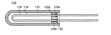
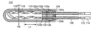
- FIG. 4A shows a modification of the sheath heater 110 shown in FIG. 1A.
- FIG. 4A is a cross-sectional view showing the configuration of the sheath heater 110.
- 4B, 4C and 4D are views showing a method of manufacturing the sheath heater 110.
- FIG. 5 is a diagram showing a flowchart for explaining a method of manufacturing the sheath heater 110.
- the cross-sectional view showing the configuration along the chain lines B1 and B2 in FIG. 4A is the same as that in FIG. 1B.
- the cross-sectional view showing the configuration along the chain lines C1 and C2 in FIG. 4A is a configuration in which the first insulating member 122 is replaced with the first insulating member 122a in FIG.
- FIG. 1C The cross-sectional view showing the configuration along the chain lines D1 and D2 in FIG. 4A is the same as that in FIG. 1D.
- the cross-sectional view showing the configuration along the chain lines E1 and E2 in FIG. 4A is the same as that in FIG. 1E.
- the cross-sectional view showing the configuration along the chain lines F1 and F2 in FIG. 4A is the same as that in FIG. 1F.
- the description of the same or similar configuration as in FIGS. 1A to 3 may be omitted. Similar to FIG. 1A, in FIG. 4A, the right side is referred to as an upper portion and the left side is referred to as a lower portion.
- the first insulating member 122 becomes two members, the first insulating member 122a and the first insulating member 122b, and the third insulating body is the first insulating member 122a and the first insulating member 122a. It differs from the sheath heater 110 shown in FIG. 1A in that it is provided between the insulating members 122b of the above.
- the sheath heater 110 shown in FIG. 4A is the same as the sheath heater 110 shown in FIG. 1A except for the above points, and thus the description thereof is omitted here.
- the first insulating member 122 becomes two members, the first insulating member 122a and the first insulating member 122b.
- a third insulator 132 is provided between the first insulating member 122a and the first insulating member 122b.
- a first insulating member 122a is provided on the upper part of the first insulating body 116.
- the first insulating member 122a is provided inside the metal sheath 115 so as to be in contact with the upper part of the first insulator 116 and at least a part of the inside of the metal sheath 115 without protruding from the upper part of the metal sheath 115.
- the outer diameter of the first insulating member 122a is the same as the outer diameter of the first insulating member 122.
- the first insulating member 122a has at least a first through hole 123a and a second through hole 123b.
- the hole diameter of the first through hole 123a and the hole diameter of the second through hole 123b are different from the first insulating member 122 in that they are substantially the same or the same in the upper part and the lower part of the first insulating member 122a.
- FIG. 4A how the heater wire 118 taken out from the second end (open end) of the metal sheath 115 is inserted into the first insulating member 122a, the heater wire 118 with respect to the first insulating member 122a, Since the positional relationship between the metal sheath 115, the first through hole 123a, and the second through hole 123b is the same as the configuration of the sheath heater 110 shown in FIG. 1A, the description thereof is omitted here.
- the first insulating member 122a may be referred to as a protective tube, an insulating tube, or the like, like the first insulating member 122.
- a third insulator 132 is provided on the upper portion of the first insulating member 122a.
- the third insulator 132 is in contact with the upper part of the first insulating member 122a and at least a part of the inside of the metal sheath 115, and is provided inside the metal sheath 115 without protruding from the upper part of the metal sheath 115.
- the third insulator 132 is sometimes called a sealant, an adhesive, or the like.
- the third insulator 132 connects the first insulating member 122a and the first insulating member 122b.
- the third insulator 132 prevents the intrusion of moisture such as moisture and solvent into the sheath heater 110, and suppresses expansion and deterioration of the first insulator 116.
- a first insulating member 122b is provided on the upper portion of the third insulating body 132.
- the first insulating member 122b is provided so as to be in contact with the upper portion of the third insulator 132 and at least a part of the inside of the metal sheath 115 and project from the upper portion of the metal sheath 115. Since the first insulating member 122b has the same configuration as the first insulating member 122, detailed description here will be omitted.
- Step 30 S30
- step 35 S35
- step 37 S37
- step 39 S39
- step 41 S41
- step 43 S43
- both ends of the heater wire 118 taken out from one end of the metal sheath 115 are inserted into the first insulating member 122a. Specifically, one of both ends of the heater wire 118 is inserted into the first through hole 123a included in the first insulating member 122, and the other end of the heater wire 118 is inserted into the first through hole 123a. It is inserted into the second through hole 123b included in the insulating member 122. The first insulating member 122 through which both ends of the heater wire 118 are inserted is fitted into the metal sheath 115 surrounding the first insulator 116 and the heater wire 118.
- the first insulating member 122 Since the outer diameter of the metal sheath 115 and the outer diameter of the first insulating member 122 are substantially the same or the same diameter, the first insulating member 122 is fixed to the metal sheath 115 surrounding the heater wire 118 by step 31. can do.
- the first insulating member 122 uses a ceramic-based insulating tube having two through holes.
- the third insulator 132 is applied so as to be in contact with a part of the inner wall of the metal sheath 115 and the first insulating member 122a.
- the third insulator 132 the same material as that of the second insulator 136 can be used.
- the third insulator 132 is formed by using, for example, a fluorine-based adhesive.
- step 33 (S33) of FIGS. 4D and 5 both ends of the heater wire 118 taken out from one end of the metal sheath 115 are inserted into the first insulating member 122b. Since the description of step 33 (S33) of FIGS. 4D and 5 is the same as the description of replacing the first insulating member 122 described in step 33 (33) of FIG. 3 with the first insulating member 122b. Detailed description here will be omitted.
- the first insulating member 122 becomes two members, the first insulating member 122a and the first insulating member 122b, and the third insulating member 132 is the third member. It is provided between the insulating member 122a of 1 and the insulating member 122b of the first.
- the third insulator 132 is an adhesive or a sealing agent like the second insulator 136, and contains an organic resin.
- the bending force can be alleviated at least in the vicinity of the second insulator 136, in the vicinity of the third insulator 132, or in two steps. Therefore, in the sheath heater according to the embodiment of the present invention, by having the above-described configuration, it is possible to prevent the sheath heater 110 having a reduced diameter from being damaged and the heating wire in the sheath heater 110 having a reduced diameter from being broken. A highly reliable sheath heater can be provided.
- stage 100 according to one embodiment of the present invention will be described.
- the description of the same or similar configuration as that of the first embodiment may be omitted.
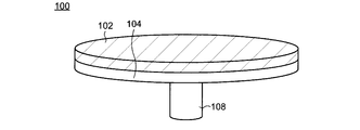
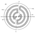
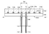
- FIGS. 6A and 6B A perspective view and a top view of the stage 100 are shown in FIGS. 6A and 6B, respectively.
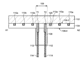
- Cross-sectional views along the chain lines A1 and A2 of FIG. 6B are shown in FIGS. 7A and 7B.
- the stage 100 has a first support plate 102, a second support plate 104, a shaft 108, and at least one sheath heater 110.
- 6A to 7B show an example in which two sheath heaters, a first sheath heater 110a and a second sheath heater 110b, are provided.
- the first support plate 102 is not shown in FIG. 6B
- the sheath heater 110 is not shown in FIG. 7B.
- the first support plate 102 is configured so that its upper surface is flat in order to arrange a semiconductor substrate containing silicon or a compound semiconductor, an insulating substrate containing an insulator such as quartz or glass, or the like on the semiconductor substrate.
- the first support plate contains a metal, and the metal is selected from metals having a thermal conductivity of 10 W / mK or more and 430 W / mK or less.
- the metal preferably has a coefficient of thermal expansion of 5 ⁇ 10 -6 / K or more and 25 ⁇ 10 -6 / K or less. Specific metals satisfying such characteristics include metals such as titanium, aluminum, and stainless steel.
- an electrostatic chuck for fixing the substrate a through hole for supplying a gas having high thermal conductivity such as helium between the substrate and the stage 100, or a through hole on the first support plate 102, or A ring flow path for circulating the liquid medium may be provided.
- the second support plate 104 is provided below the first support plate 102.
- the second support plate 104 also contains metals that can be used in the first support plate 102.
- the metal contained in the second support plate 104 and the metal contained in the first support plate 102 may be the same or different. If they are different, each metal may be selected so that the difference in the coefficient of thermal expansion of the metals contained in the first support plate 102 and the second support plate 104 is 10 ⁇ 10 -6 / K or less. it can. As a result, deformation due to thermal expansion can be suppressed, and a highly reliable stage 100 can be provided.
- the upper surface 104-3 of the second support plate 104 is joined to the first support plate 102.
- the joining of the first support plate 102 and the second support plate 104 can be performed by welding, screwing, or brazing. Alloys containing silver, copper, and zinc, alloys containing copper and zinc, copper containing trace amounts of phosphorus, aluminum and its alloys, alloys containing titanium, copper, and nickel, titanium, zirconium are used in brazing. , And alloys containing copper, alloys containing titanium, zirconium, copper, and nickel, and the like.
- the stage 100 may further have a third support plate (not shown).
- the third support plate which is an arbitrary configuration, is arranged under the second support plate 104.
- the third support plate includes a configuration similar to that of the first support plate 102 or the second support plate 104.
- the third support plate is joined to the lower surface 104-4 of the second support plate 104. Similar to the joining of the first support plate 102 and the second support plate 104, the joining of the third support plate and the second support plate 104 can be performed by welding, screwing, brazing, or the like.
- the shaft 108 is provided to support the first support plate 102 and the second support plate 104. It has a hollow structure for storing the lead wire 112 for supplying electric power to the heater wire 118 of the sheath heater 110, which will be described later.
- wiring for supplying electric power to the electrostatic chuck is also arranged in the shaft 108.
- the shaft 108 may be connected to a rotation mechanism. By connecting the shaft 108 to the rotation mechanism, the stage 100 can be rotated about the long axis of the shaft 108.
- the shaft 108 is joined to the second support plate 104 by welding, screwing, brazing, or the like.
- the shaft 108 is joined to the third support plate and also supports the third support plate.
- the configuration described in the first embodiment can be applied to the sheath heater 110.
- the sheath heater 110 has a function of generating heat when energized.
- the sheath heater 110 is provided to heat the second support plate 104 and the first support plate 102. As a result, the substrate installed on the stage 100 is heated.
- a groove (first groove 120) is provided on the upper surface 104-3 of the second support plate 104 (FIG. 7B), and the first sheath heater 110a and the second sheath heater 110b are arranged in the first groove 120.
- the first support plate 102 has a flat lower surface, and no groove is provided on the lower surface. Therefore, the depth of the first groove 120 is the same as or substantially the same as the outer diameter of the sheath heater 110. Specifically, the depth of the first groove 120 is greater than 100% of the outer diameter of the sheath heater 110 and 150% or less, greater than 100% and 120% or less, or greater than 100% and 110% or less. Just do it.
- the first groove 120 is formed so as to exist in the upper surface 104-3 at a uniform density.
- the first end T1 of the first sheath heater 110a is located within the region 109 where the first support plate 102 and the second support plate 104 overlap the shaft 108 (the region represented by the chain line circle in FIG. 6B). To do.
- the first sheath heater 110a bent at the first end T1 passes through the through hole 130 (FIG. 7B) formed in the second support plate 104, extends into the shaft 108, and further extends the lead wire 112, It is connected to a heater power supply (not shown) via the terminal 114 (FIG. 6A).
- the first end T2 of the second sheath heater 110b also has a region where the first support plate 102 and the second support plate 104 overlap the shaft 108 ( It is located within 109 (the region indicated by the chain line circle in FIG. 6B).
- the second sheath heater 110b bent at the first end T2 passes through the through hole 130 (FIG. 7B) formed in the second support plate 104, extends into the shaft 108, and further extends the lead wire 112, It is connected to a heater power supply (not shown) via the terminal 114 (FIG. 6A).
- the diameter of the conventional sheath heater is larger than the diameter of the sheath heater 110 provided in the stage 100 according to the embodiment of the present invention. Since the size of the shaft 108 included in the stage is limited, when a large number of conventional sheath heaters are used for the stage, it becomes difficult to arrange the ends of a large number of conventional sheath heaters in the region 109. As a result, the number of sheath heaters that can be placed is limited. Therefore, it is not possible to divide the upper surface of the stage into a plurality of segments and precisely control the temperature for each segment. Therefore, it becomes difficult to uniformly heat the substrate.
- the diameter of the sheath heater 110 provided in the stage 100 according to the embodiment of the present invention is small. Therefore, even if a plurality of sheath heaters 110 are arranged on the stage 100, the ends of the large number of sheath heaters can be arranged in the region 109. Further, the degree of freedom in arranging a large number of sheath heaters 110 is high, and the upper surface of the stage can be divided into a plurality of segments, and the temperature can be precisely controlled for each segment. Therefore, it is possible to uniformly heat the substrate.
- FIGS. 8A and 8B are cross-sectional views taken along the chain lines A1 and A2 of FIG. 6B, similarly to FIG. 7A.
- the description of the configuration that is the same as or similar to that of the first embodiment or the second embodiment may be omitted.
- Modification 1 As shown in FIG. 8A, in the first modification, the groove (first groove 120) is not formed on the upper surface 104-3 of the second support plate 104, and the groove (second groove 120) is not formed on the lower surface of the first support plate 102. Groove 140) is formed. In the first modification, the sheath heater 110 is housed in the second groove 140. The depth of the second groove 140 is the same as or substantially the same as the outer diameter of the sheath heater 110. Specifically, the depth of the second groove 140 is greater than 100% and less than 150% of the outer diameter of the sheath heater 110, greater than 100% and less than 120%, or greater than 100% and less than 110%. Just do it.
- the contact area between the sheath heater 110 and the first support plate 102 can be increased by making the depth of the second groove 140 the same as or substantially the same as the outer diameter of the sheath heater 110. Therefore, the heat energy generated by the sheath heater 110 can be efficiently transferred to the first support plate 102.
- the depth of the second groove 140 is the same as or substantially the same as the outer diameter of the sheath heater 110 is illustrated, but the depth of the second groove 140 is not limited to this configuration.
- the outer diameter of the sheath heater 110 and the depth of the second groove 140 may be different.
- the first groove 120 is formed on the upper surface 104-3 of the second support plate 104, and the second groove 140 is formed on the lower surface of the first support plate 102.
- the sum of the depth of the first groove 120 and the depth of the second groove 140 is the same as or substantially the same as the outer diameter of the sheath heater 110.
- the sum of the depth of the first groove 120 and the depth of the second groove 140 is greater than 100% of the outer diameter of the sheath heater 110 and 150% or less, greater than 100% and 120% or less, or It may be larger than 100% and 110% or less.
- the sum of the depth of the first groove 120 and the depth of the second groove 140 is the same as or substantially the same as the outer diameter of the sheath heater 110, so that the sheath heater 110 and the first support plate 102 and The contact area with the second support plate 104 can be increased. Therefore, the thermal energy generated by the sheath heater 110 can be efficiently transferred to the first support plate 102 and the second support plate 104.
- the sum of the depth of the second groove 140 and the depth of the second groove 140 is not limited to this configuration.
- the sum of the outer diameter of the sheath heater 110 and the depth of the first groove 120 and the depth of the second groove 140 may be different.
- a stage 150 in which a plurality of independently driven sheath heaters 110 are arranged will be described.
- the following aspects are an example of this embodiment, and there is no limitation on the number of sheath heaters 110 provided on the stage 100.
- the description of the configuration that is the same as or similar to that of the first to third embodiments may be omitted.
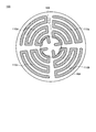
- FIG. 9 shows a top view of the stage 150.
- the first support plate 102 is not shown in FIG.
- each of the four sheath heaters (first sheath heater 110a, second sheath heater 110b, third sheath heater 110c, and fourth sheath heater 110d) is within one quadrant in the stage 150. Is placed in. That is, four sheath heaters (first sheath heater 110a, second sheath heater 110b, third sheath heater 110c, and fourth sheath heater 110d) are arranged symmetrically on the stage 150. In the example shown in FIG. 9, the first sheath heater 110a to the fourth sheath heater 110d having arcs having different radii are arranged.
- the first sheath heater 110a to the fourth sheath heater 110d have the same shape, and one of the first sheath heater 110a to the fourth sheath heater 110d is 90 ° on an axis passing through the center of the second support plate 104. When rotated, it can be placed so that it overlaps with the other one.
- the layout as described above since the diameters of the plurality of sheath heaters 110 provided in the stage 150 according to the embodiment of the present invention are small, the ends of the plurality of sheath heaters 110 should be arranged in the region 109. Can be done. Further, by adopting the layout as described above, a plurality of sheath heaters 110 having high symmetry can be arranged at a high density on the second support plate 104. Therefore, it is possible to control the temperature of the substrate more uniformly and precisely.
- FIG. 10A a cross-sectional view of a single-terminal sheath heater 110 provided with a band-shaped heater wire 118 is shown in FIG. 10A).
- FIG. 10B is a diagram showing a cross section along the chain lines G1 and G2 perpendicular to the long axis.
- FIG. 11A shows a cross-sectional view of a single-terminal sheath heater 110 provided with a strip-shaped heater wire 118 having a spiral structure.
- FIG. 11B is a diagram showing a cross section along the chain lines H1 and H2 perpendicular to the long axis.
- FIG. 12A shows a cross-sectional view of a single-terminal sheath heater 110 provided with a band-shaped heater wire 118 having a double helix structure.
- FIG. 12B is a diagram showing a cross section along the chain lines J1 and J2 perpendicular to the long axis.
- the sheath heater 110 shown in FIG. 10A is different from the sheath heater 110 shown in the first embodiment in that the band-shaped heater wire 118 is folded in the metal sheath 115 and both ends thereof are taken out from one end of the metal sheath 115.
- the cross-sectional shape of the sheath heater 110 illustrated in FIG. 10A is quadrangular, and a strip-shaped heater wire 118 is provided. As shown in FIG. 11A, the heater wire 118 may be twisted in the metal sheath 115, and the folded portion from one end and the folded portion from the other end may independently form a spiral structure.
- the spiral pitch L1 is 1.0 mm or more and 3.0 mm or less, 1.0 mm or more and 2.5 mm or less, or 1.0 mm or more and 2.0 mm or less. Is adjusted.
- the length of the heater wire 118 per unit of the metal sheath 115 can be increased, and the resistance value of the sheath heater 110 can be increased. Further, since the heater wire 118 can be provided with a spring property, deformation of the heater wire 118 and disconnection during thermal expansion are suppressed. Therefore, for example, even if the difference in thermal expansion coefficient between the metal sheath 115 and the heater wire 118 is large, it is possible to provide the sheath heater 110 with improved reliability.
- the normal of the heater wire 118 is substantially perpendicular to the direction in which the metal sheath 115 extends. Further, in the two portions of the heater wire 118 facing each other, the surfaces of the heater wire 118 are substantially parallel. Further, by making the winding direction of the spiral structure the same and the pitch L1 of the spiral structure substantially the same, the distance between the two portions of the heater wire 118 facing each other (the folded portion from one end of the heater wire 118 and the folded portion). The distance (distance from the other end to the folded portion) g4 can be kept constant, and as a result, a short circuit of the heater wire 118 can be prevented. However, in the two portions of the heater wire 118 facing each other, the winding direction of the spiral or the pitch L1 may be different from each other.
- the two portions of the heater wire 118 facing each other may form the heater wire 118 so as to have a double helix structure.
- the heater wire 118 is configured so that the pitch L2 of the spiral structure of the heater wire 118 is 1.0 mm or more and 6.0 mm or less, 1.0 mm or more and 2.5 mm or less, or 1.0 mm or more and 2.0 mm or less. be able to.
- the width d11 of the heater wire 118 can be selected from the range of 0.1 mm or more and 2.0 mm or less, and the thickness d12 can be selected from the range of 0.1 mm or more and 0.5 mm or less. be able to.
- the inner diameter d2 of the metal sheath 115 is selected from the range of 3.0 mm or more and 4.0 mm or less, the thickness d4 is selected from the range of 0.5 mm or more and 1.0 mm or less, and the outer diameter d3 is selected from the range of 3.0 mm or more and 6.0 mm or less. can do.
- the distance g3 between the heater wire 118 and the metal sheath 115 can be selected from the range of 0.3 mm or more and 1.0 mm or less, or 0.4 mm or more and 1.0 mm or less.
- the distance g4 between the folded portion from one end of the heater wire 118 and the folded portion from the other end is selected from the range of 0.3 mm or more and 2.0 mm or less, or 0.4 mm or more and 1.0 mm or less.
- the sheath heater 110 can be formed thin. Therefore, the sheath heater 110 can be arranged at a high density on the stage 100. Therefore, the temperature distribution of the substrate can be further reduced. Further, it is possible to secure the insulation between the metal sheath 115 and the heater wire 118 and prevent the heater wire 118 from being short-circuited.
- the shape of the cross section perpendicular to the long axis of the sheath heater 110 may be a circular shape as shown in FIG. 1B, or a polygonal shape or an elliptical shape (not shown).
- the cross-sectional shape is circular, the force required for deformation does not depend on the bending direction, so that the sheath heater 110 can be easily bent in any direction. Therefore, the sheath heater 110 can be easily arranged in the grooves formed in the first support plate 102 and the second support plate 104 shown in FIGS. 6B to 9.
- the film forming apparatus and the film processing apparatus including the stage 100 or the stage 150 described above will be described.
- a film forming apparatus and a film processing apparatus provided with a stage 100 will be described as an example. Descriptions of the same and similar configurations as those of the first to fifth embodiments may be omitted.
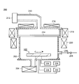
- FIG. 13 shows a cross-sectional view of an etching device 200, which is one of the film processing devices.
- the etching apparatus 200 can perform dry etching on various films.
- the etching apparatus 200 has a chamber 202.
- the chamber 202 provides a space for etching a film such as a conductor, an insulator, or a semiconductor formed on a substrate.
- An exhaust device 204 is connected to the chamber 202, whereby the inside of the chamber 202 can be set to a decompressed atmosphere.
- An introduction pipe 206 for further introducing the reaction gas is provided in the chamber 202, and the reaction gas for etching is introduced into the chamber via the valve 208.
- the reaction gas include carbon tetrafluoride (CF 4 ), octafluorocyclobutane (c C 4 F 8 ), decafluorocyclopentane (c C 5 F 10 ), hexafluorobutadiene (C 4 F 6 ), and the like. Fluorine-containing organic compounds can be mentioned.
- a microwave source 212 can be provided on the upper part of the chamber 202 via a waveguide 210.
- the microwave source 212 has an antenna for supplying microwaves and the like, and outputs high-frequency microwaves such as 2.45 GHz microwaves and 13.56 MHz radio waves (RF).
- the microwave generated in the microwave source 212 propagates to the upper part of the chamber 202 by the waveguide 210 and is introduced into the chamber 202 through the window 214 containing quartz, ceramic, or the like.
- the reaction gas is turned into plasma by microwaves, and the etching of the film proceeds by the electrons, ions, and radicals contained in the plasma.
- the stage 100 Since the substrate is installed in the lower part of the chamber 202, the stage 100 according to the embodiment of the present invention is provided.
- the substrate is installed on the stage 100.
- a power supply 224 is connected to the stage 100, high-frequency power is applied to the stage 100, and an electric field due to microwaves is formed in a direction perpendicular to the surface of the stage 100 and the surface of the substrate.
- Further magnets 216, 218, and 220 can be provided on the top and sides of the chamber 202.
- the magnet 216, the magnet 218, and the magnet 220 may be a permanent magnet or an electromagnet having an electromagnetic coil.
- the magnet 216, magnet 218, and magnet 220 create a magnetic field component parallel to the stage 100 and the substrate surface, and in cooperation with the electric field generated by microwaves, the electrons in the plasma receive Lorentz force and resonate, and the stage 100 and It is bound to the surface of the substrate. As a result, high-density plasma can be generated on the substrate surface.
- a heater power supply 230 for controlling the sheath heater 110 provided on the stage 100 is further connected to the stage 100. Further, as an arbitrary configuration, the stage 100 rotates a power supply 226 for an electrostatic chuck for fixing the substrate to the stage 100, a temperature controller 228 for controlling the temperature of the medium recirculated inside the stage 100, and the stage 100. A rotation control device (not shown) for causing the rotation may be connected.
- the stage 100 according to the embodiment of the present invention is used for the etching apparatus 200.
- the substrate can be heated uniformly and the heating temperature can be precisely controlled. Therefore, the etching apparatus 200 makes it possible to uniformly etch various films provided on the substrate.
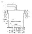
- FIG. 14 shows a cross-sectional view of a CVD device 300, which is one of the film forming devices.
- the CVD apparatus 300 has a chamber 302.
- the CVD apparatus 300 provides a place where the reaction gas is chemically reacted to chemically form various films on the substrate.
- An exhaust device 304 is connected to the chamber 302, and the pressure in the chamber 302 can be reduced.
- An introduction pipe 306 for introducing the reaction gas is further provided in the chamber 302, and the reaction gas for film formation is introduced into the chamber 302 via the valve 308.
- the reaction gas various gases can be used depending on the membrane to be produced.
- the gas may be a liquid at room temperature.
- a thin film such as silicon, silicon oxide, or silicon nitride can be formed by using silane, dichlorosilane, tetraethoxysilane, or the like.
- tungsten fluoride, trimethylaluminum, or the like a metal thin film such as tungsten or aluminum can be formed.
- a microwave source 312 may be provided above the chamber 302 via a waveguide 310.
- the microwave generated at the microwave source 312 is introduced into the chamber 302 by the waveguide 310.
- the reaction gas is turned into plasma by microwaves, the chemical reaction of the gas is promoted by various active species contained in the plasma, and the product obtained by the chemical reaction is deposited on the substrate to form a thin film.
- a magnet 344 for increasing the density of plasma can be provided in the chamber 302.
- the stage 100 described in the first embodiment is provided in the lower part of the chamber 302, and the thin film can be deposited while the substrate is placed on the stage 100.
- a magnet 316 and a magnet 318 may be further provided on the side surface of the chamber 302.
- a heater power supply 330 that controls the sheath heater 110 provided on the stage 100 is further connected to the stage 100. Further, in the stage 100, as an arbitrary configuration, a power supply 324 for supplying high frequency power to the stage 100, a power supply 326 for an electrostatic chuck, a temperature controller 328 for controlling the temperature of a medium recirculated inside the stage 100, and a stage. A rotation control device (not shown) for rotating the 100 may be connected.
- FIG. 15 shows a cross-sectional view of a sputtering device 400, which is one of the film forming devices.
- the sputtering apparatus 400 has a chamber 402.
- the sputtering apparatus 400 provides a field for colliding a high-speed ion with a target and depositing a target atom generated at that time on a substrate.
- An exhaust device 404 for reducing the pressure inside the chamber 402 is connected to the chamber 402.
- the chamber 402 is provided with an introduction pipe 406 and a valve 408 for introducing a sputter gas such as argon into the chamber 402.
- a target stage 410 that holds a target containing a material to be formed and functions as a cathode is provided in the lower part of the chamber 402, and a target 412 is installed on the target stage 410.
- a high frequency power supply 414 is connected to the target stage 410, and plasma can be generated in the chamber 402 by the high frequency power supply 414.
- the stage 100 described in the first embodiment can be provided on the upper part of the chamber 402. In this case, the formation of the thin film proceeds with the substrate placed under the stage 100. Similar to the etching apparatus 200 and the CVD apparatus 300, the heater power supply 430 is connected to the stage 100. Further, a power supply 424 for supplying high-frequency power to the stage 100, a power supply 426 for an electrostatic chuck, a temperature controller 428, and a rotation control device (not shown) for rotating the stage 100 are connected to the stage 100. May be good.
- the present embodiment a configuration in which the stage 100 is installed above the chamber 402 and the target stage 410 is installed below the chamber 402 is exemplified, but the present embodiment is not limited to this configuration, and the target 412 is above the stage 100.
- the sputtering apparatus 400 may be configured so as to be located at.
- the stage 100 may be installed so that the main surface of the substrate is arranged perpendicular to the horizontal plane, and the target stage 410 may be provided so as to face the stage 100.
- FIG. 16 shows a cross-sectional view of a vapor deposition apparatus 500, which is one of the film-forming apparatus.
- the vapor deposition apparatus 500 has a chamber 502.
- the vapor deposition apparatus 500 provides a space for evaporating the material in the vapor deposition source 510 and depositing the evaporated material on the substrate.
- An exhaust device 504 for creating a high vacuum inside the chamber 502 is connected to the chamber 502.
- the chamber 502 is provided with an introduction pipe 506 for returning the chamber 502 to atmospheric pressure, and an inert gas such as nitrogen or argon is introduced into the chamber 502 via a valve 508.
- a stage 100 can be provided on the upper part of the chamber 502. Material deposition proceeds with the substrate placed under stage 100. Similar to the etching apparatus 200, the CVD apparatus 300, and the sputtering apparatus 400, a heater power supply 528 is further connected to the stage 100. Further, as an arbitrary configuration, a power supply 524 for the electrostatic chuck, a temperature controller 526, and a rotation control device 530 for rotating the stage 100 may be connected to the stage 100.
- the stage 100 may further have a mask holder 516 for fixing the metal mask between the substrate and the deposition source 510. As a result, the metal mask can be arranged in the vicinity of the substrate so that the opening of the metal mask overlaps the region where the material is deposited.
- the thin-film deposition source 510 is provided on the lower side of the chamber, and the material to be deposited is filled in the thin-film deposition source 510.
- the vapor deposition source 510 is provided with a heater for heating the material, and the heater is controlled by the control device 512.
- Evacuation is started by creating a high vacuum in the chamber 502 using the exhaust device 504 and heating the vapor deposition source 510 to vaporize the material. By opening the shutter 514 when the vapor deposition rate becomes constant, deposition of the material is started on the substrate.
- the stage according to the embodiment of the present invention is used for the film forming apparatus such as the CVD apparatus 300, the sputtering apparatus 400, or the vapor deposition apparatus 500 of the present embodiment.
- the substrate can be heated uniformly and the heating temperature can be precisely controlled. Therefore, by using these film forming devices, it is possible to uniformly form various films having controlled characteristics on the substrate.
- 100 Stage, 102: First support plate, 104: Second support plate, 104-3: Top surface, 104-4: Bottom surface, 108: Shaft, 109: Region, 110: Sheath heater, 110a: First sheath heater , 110b: 2nd sheath heater, 110c: 3rd sheath heater, 110d: 4th sheath heater, 112: lead wire, 114: terminal, 115: metal sheath, 116: first insulator, 118: heater wire, 120 : 1st groove, 122: 1st insulating member, 122a: 1st insulating member, 125: projecting portion, 122b: 1st insulating member, 123: 1st through hole, 123a: 1st through hole , 123b: 2nd through hole, 124: lid-like member, 124a: 1st hole, 124b: 2nd hole, 128: 2nd insulating member, 128a: 2nd insulating member, 128b: 2nd
Landscapes
- Chemical & Material Sciences (AREA)
- Engineering & Computer Science (AREA)
- Mechanical Engineering (AREA)
- Organic Chemistry (AREA)
- Metallurgy (AREA)
- Chemical Kinetics & Catalysis (AREA)
- Materials Engineering (AREA)
- General Chemical & Material Sciences (AREA)
- Physics & Mathematics (AREA)
- Manufacturing & Machinery (AREA)
- Plasma & Fusion (AREA)
- Electromagnetism (AREA)
- Resistance Heating (AREA)
- Chemical Vapour Deposition (AREA)
- Drying Of Semiconductors (AREA)
- Physical Vapour Deposition (AREA)
Abstract
Description
本実施形態では、本発明の一実施形態に係るシースヒータ110に関して説明する。
シースヒータ110の断面図を図1A乃至図1Fに示す。図1Aはシースヒータ110の構成を示す断面図である。図1Bは鎖線B1とB2に沿った構成を示す断面図である。図1Cは鎖線C1とC2に沿った構成を示す断面図である。図1Dは鎖線D1とD2に沿った構成を示す断面図である。図1Eは鎖線E1とE2に沿った構成を示す断面図である。図1Fは鎖線F1とF2に沿った構成を示す断面図である。
図2A乃至図2Dはシースヒータ110の作製方法を示す断面図である。図3はシースヒータ110の作製方法を説明するためのフローチャートを示す図である。図1A、図2A乃至図2Dにおいて、右側を上部、左側を下部と呼ぶ。図1A乃至図1Fと同一、または類似する構成については説明を省略することがある。
図1Aに示されたシースヒータ110の変形例を図4Aに示す。図4Aはシースヒータ110の構成を示す断面図である。図4B、図4C及び図4Dは、シースヒータ110の製造方法を示す図である。図5はシースヒータ110の作製方法を説明するためのフローチャートを示す図である。図4Aにおいて鎖線B1とB2に沿った構成を示す断面図は図1Bと同様である。図4Aにおいて鎖線C1とC2に沿った構成を示す断面図は、図1Cにおいて、第1の絶縁部材122を第1の絶縁部材122aに置き換えた構成である。図4Aにおいて鎖線D1とD2に沿った構成を示す断面図は図1Dと同様である。図4Aにおいて鎖線E1とE2に沿った構成を示す断面図は図1Eと同様である。図4Aにおいて鎖線F1とF2に沿った構成を示す断面図は図1Fと同様である。図1A乃至図3と同一、または類似する構成については説明を省略することがある。なお、図1Aと同様に、図4Aにおいても、右側を上部、左側を下部と呼ぶ。
本実施形態では、本発明の一実施形態に係るステージ100に関して説明する。第1実施形態と同一、または類似する構成については説明を省略することがある。
本実施形態では、第2実施形態で述べたステージ100の変形例を図8Aおよび図8Bを用いて説明する。これらの図は、図7Aと同様に、図6Bの鎖線A1とA2とに沿った断面図である。第1実施形態または第2実施形態と同一、または類似する構成については説明を省略することがある。
図8Aに示すように、変形例1では、第2の支持プレート104の上面104-3に溝(第1の溝120)は形成されず、第1の支持プレート102の下面に溝(第2の溝140)が形成される。変形例1では、シースヒータ110は第2の溝140内に収納される。第2の溝140の深さは、シースヒータ110の外径と同一、またはほぼ同一である。具体的には、第2の溝140の深さは、シースヒータ110の外径の100%よりも大きく150%以下、100%よりも大きく120%以下、または100%よりも大きく110%以下とすればよい。
図8Bに示すように、変形例2では、第2の支持プレート104の上面104-3に第1の溝120を形成するとともに、第1の支持プレート102の下面に第2の溝140を形成してもよい。変形例2では、第1の溝120の深さと第2の溝140の深さの和は、シースヒータ110の外径と同一、またはほぼ同一である。具体的には、第1の溝120の深さと第2の溝140の深さの和は、シースヒータ110の外径の100%よりも大きく150%以下、100%よりも大きく120%以下、または100%よりも大きく110%以下とすればよい。
本実施形態では、独立に駆動される複数のシースヒータ110が配置されたステージ150について説明する。以下に示す態様は本実施形態の一例であり、ステージ100に設けられるシースヒータ110の数に制約はない。第1実施形態乃至第3実施形態と同一、または類似する構成については説明を省略することがある。
本実施形態では、第1実施形態とは異なるシースヒータ110の構造を説明する。第1実施形態と同一、または類似する構成については説明を省略することがある。
本実施形態では、上述したステージ100、またはステージ150を備える成膜装置と膜加工装置について説明する。本実施形態ではステージ100が備えられた成膜装置および膜加工装置を例として説明する。第1実施形態乃至第5実施形態と同一、類似する構成に関しては説明を省略することがある。
図13には、膜加工装置の一つであるエッチング装置200の断面図が示されている。エッチング装置200は、種々の膜に対してドライエッチングを行うことができる。エッチング装置200は、チャンバー202を有している。チャンバー202は、基板上に形成された導電体、絶縁体、または半導体などの膜に対してエッチングを行う空間を提供する。
図14は、成膜装置の一つであるCVD装置300の断面図が示されている。CVD装置300はチャンバー302を有している。CVD装置300は、反応ガスを化学的に反応させ、種々の膜を基板上に化学的に形成する場を提供する。
図15は、成膜装置の一つであるスパッタ装置400の断面図が示されている。スパッタ装置400はチャンバー402を有する。スパッタ装置400は、高速のイオンとターゲットの衝突、およびその際に発生するターゲット原子を基板上に堆積させるための場を提供する。
図16は、成膜装置の一つである蒸着装置500の断面図が示されている。蒸着装置500はチャンバー502を有する。蒸着装置500は、蒸着源510における材料の蒸発、ならびに蒸発した材料を基板上へ堆積させるための空間が提供される。
Claims (17)
- 折りたたまれたヒータ線、
前記ヒータ線に設けられた第1の絶縁体、
前記第1の絶縁体の少なくとも一部に接するように設けられた金属シース、
前記金属シースの第1の端部から取り出された前記ヒータ線の一方の少なくとも一部に平行に配置された第1の絶縁部材、
前記第1の絶縁部材の少なくとも一部に平行に配置され、前記金属シースの第1の端部から取り出された前記ヒータ線の他方の少なくとも一部に平行に配置された第2の絶縁部材、
前記金属シース、前記第1の絶縁部材および前記第2の絶縁部材の少なくとも一部に接する第2の絶縁体、および、
前記第1の絶縁部材の一部を覆い、前記第2の絶縁体を介して、前記金属シース、前記第1の絶縁部材および前記第2の絶縁部材の少なくとも一部に接し、前記金属シース、前記第1の絶縁部材および前記第2の絶縁部材の少なくとも一部に平行に配置される蓋状部材、
を有するヒータ。 - 前記蓋状部材は、凹部を有し、所定の厚みを有する一つの部材から構成される、請求項1に記載のヒータ。
- 前記蓋状部材の内径は、前記第1の絶縁部材の外径と略同一であり、前記蓋状部材の外径は、前記金属シースの外径と略同一である、請求項1に記載のヒータ。
- 前記金属シースの内径と前記第1の絶縁部材の外径とは略同一であり、
前記第1の絶縁部材は前記金属シースに挿通されている、
請求項1に記載のヒータ。 - 前記第1の絶縁部材は突出部を有し、前記蓋状部材は前記第2の絶縁体を介して前記突出部に嵌る、請求項1に記載のヒータ。
- 前記突出部は、前記金属シースが設けられている方向とは反対の方向に突出している、請求項5に記載のヒータ。
- 前記第1の絶縁部材は貫通孔を有し、
前記第2の絶縁部材は、前記貫通孔に挿通される、
請求項1に記載のヒータ。 - 前記貫通孔の孔径は前記第1の絶縁部材の上部と下部において異なる、
請求項7に記載のヒータ。 - 前記貫通孔の断面は、前記異なる孔径の接続部分において階段状であり、
前記第2の絶縁部材は、前記接続部分まで挿通される、
請求項8に記載のヒータ。 - 前記ヒータ線は帯状である、請求項1に記載のヒータ。
- 前記ヒータ線はらせん構造を有する、請求項1に記載のヒータ。
- 前記ヒータ線は、二重らせん構造を有する、請求項1に記載のヒータ。
- 前記第2の絶縁体は、封止剤または接着剤である、請求項1に記載のヒータ。
- 前記金属シースはアルミニウムを含む、請求項1に記載のヒータ。
- 前記金属シースの外径は3.0mm以上6.0mm以下である、請求項1に記載のヒータ。
- 前記蓋状部材はアルミニウムを含む、請求項1に記載のヒータ。
- 前記蓋状部材の外径は3.0mm以上6.0mm以下である、請求項1に記載のヒータ。
Priority Applications (4)
| Application Number | Priority Date | Filing Date | Title |
|---|---|---|---|
| CN202080051682.2A CN114127905B (zh) | 2019-08-02 | 2020-07-06 | 加热器和载物台 |
| EP20850532.1A EP4009740B1 (en) | 2019-08-02 | 2020-07-06 | Heater |
| KR1020227005014A KR102776400B1 (ko) | 2019-08-02 | 2020-07-06 | 히터 및 스테이지 |
| US17/582,848 US20220151031A1 (en) | 2019-08-02 | 2022-01-24 | Heater |
Applications Claiming Priority (2)
| Application Number | Priority Date | Filing Date | Title |
|---|---|---|---|
| JP2019142732A JP6788079B1 (ja) | 2019-08-02 | 2019-08-02 | ヒータ、およびステージ |
| JP2019-142732 | 2019-08-02 |
Related Child Applications (1)
| Application Number | Title | Priority Date | Filing Date |
|---|---|---|---|
| US17/582,848 Continuation US20220151031A1 (en) | 2019-08-02 | 2022-01-24 | Heater |
Publications (1)
| Publication Number | Publication Date |
|---|---|
| WO2021024672A1 true WO2021024672A1 (ja) | 2021-02-11 |
Family
ID=73220024
Family Applications (1)
| Application Number | Title | Priority Date | Filing Date |
|---|---|---|---|
| PCT/JP2020/026410 Ceased WO2021024672A1 (ja) | 2019-08-02 | 2020-07-06 | ヒータ、およびステージ |
Country Status (7)
| Country | Link |
|---|---|
| US (1) | US20220151031A1 (ja) |
| EP (1) | EP4009740B1 (ja) |
| JP (1) | JP6788079B1 (ja) |
| KR (1) | KR102776400B1 (ja) |
| CN (1) | CN114127905B (ja) |
| TW (1) | TWI750745B (ja) |
| WO (1) | WO2021024672A1 (ja) |
Cited By (3)
| Publication number | Priority date | Publication date | Assignee | Title |
|---|---|---|---|---|
| JP2022156762A (ja) * | 2021-03-31 | 2022-10-14 | 日本発條株式会社 | シースヒータ及びそれを有する基板支持装置 |
| WO2024018716A1 (ja) * | 2022-07-20 | 2024-01-25 | 日本発條株式会社 | ヒータユニット |
| RU240034U1 (ru) * | 2025-10-09 | 2025-12-22 | Федеральное государственное бюджетное образовательное учреждение высшего образования "Уфимский государственный нефтяной технический университет" | Высокотемпературный трубчатый электрический нагреватель |
Families Citing this family (5)
| Publication number | Priority date | Publication date | Assignee | Title |
|---|---|---|---|---|
| US10765597B2 (en) * | 2014-08-23 | 2020-09-08 | High Tech Health International, Inc. | Sauna heating apparatus and methods |
| JP7594852B2 (ja) * | 2018-10-11 | 2024-12-05 | 日本発條株式会社 | ステージ、成膜装置、および膜加工装置 |
| JP7566170B2 (ja) * | 2022-06-23 | 2024-10-11 | 株式会社日立ハイテク | プラズマ処理装置 |
| JP7890098B2 (ja) * | 2022-07-13 | 2026-07-14 | 日本発條株式会社 | シースヒータおよびステージ |
| CN119542247B (zh) * | 2025-01-23 | 2025-05-06 | 四川艾庞机械科技有限公司 | 一种用于led芯片干法蚀刻的载片治具 |
Citations (5)
| Publication number | Priority date | Publication date | Assignee | Title |
|---|---|---|---|---|
| JPS54126146U (ja) * | 1978-02-22 | 1979-09-03 | ||
| JPS6318790U (ja) * | 1986-07-22 | 1988-02-06 | ||
| JPS63166193A (ja) * | 1986-12-26 | 1988-07-09 | 松下電器産業株式会社 | シ−ズヒ−タ |
| JP2009091660A (ja) | 1996-04-19 | 2009-04-30 | Akt Kk | 被加熱型基板支持構造体 |
| US20150001206A1 (en) * | 2013-06-26 | 2015-01-01 | Tuerk & Hillinger Gmbh | Electric cartridge type heater and method for manufacturing same |
Family Cites Families (11)
| Publication number | Priority date | Publication date | Assignee | Title |
|---|---|---|---|---|
| US2009980A (en) * | 1931-07-30 | 1935-07-30 | Gen Electric | Electric heating unit |
| US3839623A (en) * | 1973-08-30 | 1974-10-01 | Watlow Electric Mfg Co | Electric heater with add-on leads |
| FR2608884B3 (fr) * | 1986-12-18 | 1989-04-07 | Metanic Sa | Dispositif de chauffage par resistance electrique a double isolement |
| JPH10169982A (ja) * | 1996-12-11 | 1998-06-26 | Isuzu Ceramics Kenkyusho:Kk | セラミックヒータ及びその製造方法 |
| JP3922497B2 (ja) * | 1998-06-25 | 2007-05-30 | 株式会社日立国際電気 | 加熱装置およびシース熱電対 |
| CN101953226B (zh) * | 2008-01-29 | 2014-01-01 | 株式会社东热 | 浸渍型加热器 |
| JP4987821B2 (ja) * | 2008-08-18 | 2012-07-25 | 三洋熱工業株式会社 | シーズヒータの発熱線のリード線の固定方法 |
| JP5411470B2 (ja) * | 2008-09-01 | 2014-02-12 | 光洋サーモシステム株式会社 | 熱処理装置 |
| JP2018181586A (ja) * | 2017-04-12 | 2018-11-15 | 日本発條株式会社 | シースヒータ |
| CN207369330U (zh) * | 2017-09-20 | 2018-05-15 | 中山市金镇电热制品有限公司 | 一种条状发热管 |
| JP7272777B2 (ja) * | 2018-10-17 | 2023-05-12 | 日本発條株式会社 | ヒータ |
-
2019
- 2019-08-02 JP JP2019142732A patent/JP6788079B1/ja active Active
-
2020
- 2020-07-06 EP EP20850532.1A patent/EP4009740B1/en active Active
- 2020-07-06 KR KR1020227005014A patent/KR102776400B1/ko active Active
- 2020-07-06 WO PCT/JP2020/026410 patent/WO2021024672A1/ja not_active Ceased
- 2020-07-06 CN CN202080051682.2A patent/CN114127905B/zh active Active
- 2020-07-22 TW TW109124735A patent/TWI750745B/zh active
-
2022
- 2022-01-24 US US17/582,848 patent/US20220151031A1/en active Pending
Patent Citations (5)
| Publication number | Priority date | Publication date | Assignee | Title |
|---|---|---|---|---|
| JPS54126146U (ja) * | 1978-02-22 | 1979-09-03 | ||
| JPS6318790U (ja) * | 1986-07-22 | 1988-02-06 | ||
| JPS63166193A (ja) * | 1986-12-26 | 1988-07-09 | 松下電器産業株式会社 | シ−ズヒ−タ |
| JP2009091660A (ja) | 1996-04-19 | 2009-04-30 | Akt Kk | 被加熱型基板支持構造体 |
| US20150001206A1 (en) * | 2013-06-26 | 2015-01-01 | Tuerk & Hillinger Gmbh | Electric cartridge type heater and method for manufacturing same |
Cited By (3)
| Publication number | Priority date | Publication date | Assignee | Title |
|---|---|---|---|---|
| JP2022156762A (ja) * | 2021-03-31 | 2022-10-14 | 日本発條株式会社 | シースヒータ及びそれを有する基板支持装置 |
| WO2024018716A1 (ja) * | 2022-07-20 | 2024-01-25 | 日本発條株式会社 | ヒータユニット |
| RU240034U1 (ru) * | 2025-10-09 | 2025-12-22 | Федеральное государственное бюджетное образовательное учреждение высшего образования "Уфимский государственный нефтяной технический университет" | Высокотемпературный трубчатый электрический нагреватель |
Also Published As
| Publication number | Publication date |
|---|---|
| EP4009740A4 (en) | 2023-08-02 |
| CN114127905A (zh) | 2022-03-01 |
| TW202119863A (zh) | 2021-05-16 |
| KR102776400B1 (ko) | 2025-03-07 |
| CN114127905B (zh) | 2025-01-14 |
| JP2021026857A (ja) | 2021-02-22 |
| JP6788079B1 (ja) | 2020-11-18 |
| EP4009740B1 (en) | 2026-08-19 |
| TWI750745B (zh) | 2021-12-21 |
| US20220151031A1 (en) | 2022-05-12 |
| EP4009740A1 (en) | 2022-06-08 |
| KR20220035187A (ko) | 2022-03-21 |
Similar Documents
| Publication | Publication Date | Title |
|---|---|---|
| JP6788079B1 (ja) | ヒータ、およびステージ | |
| US12211710B2 (en) | Stage, film-forming apparatus, and film-processing apparatus | |
| JP7272777B2 (ja) | ヒータ | |
| TWI671793B (zh) | 基板支撐單元及具有基板支撐單元之膜體形成裝置 | |
| JP7703633B2 (ja) | ステージ、成膜装置、および膜加工装置 | |
| JP7015425B1 (ja) | ステージおよびその作製方法 | |
| TWI870860B (zh) | 護套加熱器及載台 |
Legal Events
| Date | Code | Title | Description |
|---|---|---|---|
| 121 | Ep: the epo has been informed by wipo that ep was designated in this application |
Ref document number: 20850532 Country of ref document: EP Kind code of ref document: A1 |
|
| NENP | Non-entry into the national phase |
Ref country code: DE |
|
| ENP | Entry into the national phase |
Ref document number: 20227005014 Country of ref document: KR Kind code of ref document: A |
|
| ENP | Entry into the national phase |
Ref document number: 2020850532 Country of ref document: EP Effective date: 20220302 |
|
| WWG | Wipo information: grant in national office |
Ref document number: 202080051682.2 Country of ref document: CN |