WO2021024887A1 - 車両用灯具及び車両 - Google Patents
車両用灯具及び車両 Download PDFInfo
- Publication number
- WO2021024887A1 WO2021024887A1 PCT/JP2020/029139 JP2020029139W WO2021024887A1 WO 2021024887 A1 WO2021024887 A1 WO 2021024887A1 JP 2020029139 W JP2020029139 W JP 2020029139W WO 2021024887 A1 WO2021024887 A1 WO 2021024887A1
- Authority
- WO
- WIPO (PCT)
- Prior art keywords
- radar
- vehicle
- lamp
- concealing
- outside
- Prior art date
- Legal status (The legal status is an assumption and is not a legal conclusion. Google has not performed a legal analysis and makes no representation as to the accuracy of the status listed.)
- Ceased
Links
Images







Classifications
-
- G—PHYSICS
- G01—MEASURING; TESTING
- G01S—RADIO DIRECTION-FINDING; RADIO NAVIGATION; DETERMINING DISTANCE OR VELOCITY BY USE OF RADIO WAVES; LOCATING OR PRESENCE-DETECTING BY USE OF THE REFLECTION OR RERADIATION OF RADIO WAVES; ANALOGOUS ARRANGEMENTS USING OTHER WAVES
- G01S13/00—Systems using the reflection or reradiation of radio waves, e.g. radar systems; Analogous systems using reflection or reradiation of waves whose nature or wavelength is irrelevant or unspecified
- G01S13/88—Radar or analogous systems specially adapted for specific applications
- G01S13/93—Radar or analogous systems specially adapted for specific applications for anti-collision purposes
- G01S13/931—Radar or analogous systems specially adapted for specific applications for anti-collision purposes of land vehicles
-
- B—PERFORMING OPERATIONS; TRANSPORTING
- B60—VEHICLES IN GENERAL
- B60Q—ARRANGEMENT OF SIGNALLING OR LIGHTING DEVICES, THE MOUNTING OR SUPPORTING THEREOF OR CIRCUITS THEREFOR, FOR VEHICLES IN GENERAL
- B60Q1/00—Arrangement of optical signalling or lighting devices, the mounting or supporting thereof or circuits therefor
- B60Q1/0017—Devices integrating an element dedicated to another function
- B60Q1/0023—Devices integrating an element dedicated to another function the element being a sensor, e.g. distance sensor, camera
-
- F—MECHANICAL ENGINEERING; LIGHTING; HEATING; WEAPONS; BLASTING
- F21—LIGHTING
- F21S—NON-PORTABLE LIGHTING DEVICES; SYSTEMS THEREOF; VEHICLE LIGHTING DEVICES SPECIALLY ADAPTED FOR VEHICLE EXTERIORS
- F21S41/00—Illuminating devices specially adapted for vehicle exteriors, e.g. headlamps
- F21S41/20—Illuminating devices specially adapted for vehicle exteriors, e.g. headlamps characterised by refractors, transparent cover plates, light guides or filters
-
- G—PHYSICS
- G01—MEASURING; TESTING
- G01S—RADIO DIRECTION-FINDING; RADIO NAVIGATION; DETERMINING DISTANCE OR VELOCITY BY USE OF RADIO WAVES; LOCATING OR PRESENCE-DETECTING BY USE OF THE REFLECTION OR RERADIATION OF RADIO WAVES; ANALOGOUS ARRANGEMENTS USING OTHER WAVES
- G01S7/00—Details of systems according to groups G01S13/00, G01S15/00, G01S17/00
- G01S7/02—Details of systems according to groups G01S13/00, G01S15/00, G01S17/00 of systems according to group G01S13/00
- G01S7/027—Constructional details of housings, e.g. form, type, material or ruggedness
-
- B—PERFORMING OPERATIONS; TRANSPORTING
- B60—VEHICLES IN GENERAL
- B60Q—ARRANGEMENT OF SIGNALLING OR LIGHTING DEVICES, THE MOUNTING OR SUPPORTING THEREOF OR CIRCUITS THEREFOR, FOR VEHICLES IN GENERAL
- B60Q1/00—Arrangement of optical signalling or lighting devices, the mounting or supporting thereof or circuits therefor
- B60Q1/02—Arrangement of optical signalling or lighting devices, the mounting or supporting thereof or circuits therefor the devices being primarily intended to illuminate the way ahead or to illuminate other areas of way or environments
- B60Q1/04—Arrangement of optical signalling or lighting devices, the mounting or supporting thereof or circuits therefor the devices being primarily intended to illuminate the way ahead or to illuminate other areas of way or environments the devices being headlights
-
- G—PHYSICS
- G01—MEASURING; TESTING
- G01S—RADIO DIRECTION-FINDING; RADIO NAVIGATION; DETERMINING DISTANCE OR VELOCITY BY USE OF RADIO WAVES; LOCATING OR PRESENCE-DETECTING BY USE OF THE REFLECTION OR RERADIATION OF RADIO WAVES; ANALOGOUS ARRANGEMENTS USING OTHER WAVES
- G01S13/00—Systems using the reflection or reradiation of radio waves, e.g. radar systems; Analogous systems using reflection or reradiation of waves whose nature or wavelength is irrelevant or unspecified
- G01S13/88—Radar or analogous systems specially adapted for specific applications
- G01S13/93—Radar or analogous systems specially adapted for specific applications for anti-collision purposes
- G01S13/931—Radar or analogous systems specially adapted for specific applications for anti-collision purposes of land vehicles
- G01S2013/9327—Sensor installation details
- G01S2013/93271—Sensor installation details in the front of the vehicles
-
- G—PHYSICS
- G01—MEASURING; TESTING
- G01S—RADIO DIRECTION-FINDING; RADIO NAVIGATION; DETERMINING DISTANCE OR VELOCITY BY USE OF RADIO WAVES; LOCATING OR PRESENCE-DETECTING BY USE OF THE REFLECTION OR RERADIATION OF RADIO WAVES; ANALOGOUS ARRANGEMENTS USING OTHER WAVES
- G01S13/00—Systems using the reflection or reradiation of radio waves, e.g. radar systems; Analogous systems using reflection or reradiation of waves whose nature or wavelength is irrelevant or unspecified
- G01S13/88—Radar or analogous systems specially adapted for specific applications
- G01S13/93—Radar or analogous systems specially adapted for specific applications for anti-collision purposes
- G01S13/931—Radar or analogous systems specially adapted for specific applications for anti-collision purposes of land vehicles
- G01S2013/9327—Sensor installation details
- G01S2013/93277—Sensor installation details in the lights
Definitions
- This disclosure relates to vehicle lamps and vehicles.
- the present disclosure relates to vehicle lamps and vehicles equipped with radars such as millimeter-wave radars and microwave radars.
- Patent Document 1 There is known a technique for mounting a radar such as a millimeter wave radar configured to acquire data indicating the surrounding environment outside the vehicle on a vehicle lamp (see, for example, Patent Document 1).
- a resin light guide plate is arranged in front of the millimeter-wave radar in order to hide the millimeter-wave radar arranged in the lighting chamber of the vehicle lighting equipment from the outside of the vehicle. Further, by injecting the light from the light source into the light guide plate, the light emission of the light guide plate can be visually recognized from the outside. In this way, the light emission of the light guide plate can conceal the millimeter wave radar from the outside of the vehicle, and the radio waves from the millimeter wave radar can be emitted to the outside of the vehicle through the light guide plate.
- the first object of the present disclosure is to improve the maintainability of a vehicle lamp equipped with a radar and a concealing unit that conceals the radar from the outside of the vehicle.
- a second object of the present disclosure is to provide a vehicle lamp capable of concealing the radar from the outside of the vehicle while ensuring the reliability of the radar mounted on the vehicle lamp.
- a third object of the present disclosure is to provide a vehicle lamp capable of concealing a plurality of radars mounted on the vehicle lamp from the outside of the vehicle without increasing the number of steps of assembling the vehicle lamp. It is to be.
- the vehicle lamp according to one aspect of the present disclosure is with the lamp housing A lamp cover that covers the opening of the lamp housing and A lighting unit arranged in the lamp chamber formed by the lamp housing and the lamp cover, A radar configured to acquire radar data indicating the surrounding environment of the vehicle by emitting radio waves toward the outside of the vehicle.
- a concealing unit arranged so as to face the radar so as to conceal the radar from the outside of the vehicle and to pass radio waves emitted from the radar.
- the concealing portion is formed integrally with the lamp cover. The positioning portion is fixed to the concealing portion and is configured to elastically engage with the support member.
- the positioning portion fixed to the concealing portion is elastically engaged with the support member. Further, the support member is fixed to the vehicle body. Further, the concealing portion is integrally formed with the lamp cover, and the concealing portion is fixed to the positioning portion.
- the elastic engagement between the positioning portion and the supporting member can be released by using a tool such as a flat-blade driver, so that the supporting member and the positioning portion are fixed with screws or the like.
- the positioning portion can be separated from the support member relatively easily.
- the components of the vehicle lighting equipment other than the support member and the radar can be relatively easily removed from the vehicle body while the support member is maintained in a fixed state to the vehicle body. ..
- the positioning portion and the support member are elastically engaged with each other to facilitate positioning between the concealing portion and the radar. be able to. In this way, it is possible to improve the maintainability of the vehicle lighting equipment provided with the radar and the concealing portion.
- the vehicle lighting fixture is mounted on the vehicle.
- a lamp housing having a first fixing portion and a second fixing portion for fixing the vehicle lamp to the vehicle,
- a lamp cover that covers the opening of the lamp housing and
- a lighting unit arranged in the lamp chamber formed by the lamp housing and the lamp cover,
- a radar configured to acquire radar data indicating the surrounding environment of the vehicle by emitting radio waves toward the outside of the vehicle, and
- a concealing unit arranged so as to face the radar so as to conceal the radar from the outside of the vehicle and to pass radio waves emitted from the radar.
- It includes a support member configured to support the radar and fixed to the lamp housing.
- the concealing portion is formed integrally with the lamp cover.
- the radar is arranged between the first fixing portion and the second fixing portion in the left-right direction of the vehicle lamp.
- the radar is arranged between the first fixed portion and the second fixed portion in the left-right direction of the vehicle lamp. Therefore, even when the lamp housing vibrates as the vehicle travels, it is possible to preferably suppress the vibration of the lamp housing from being transmitted to the radar by the first fixing portion and the second fixing portion. In this way, since it is preferably prevented that the operating performance of the radar is adversely affected by the vibration of the radar, it is possible to conceal the radar from the outside of the vehicle while ensuring the reliability of the radar. Can be provided.
- the vehicle lamp according to one aspect of the present disclosure is with the lamp housing A lamp cover that covers the opening of the lamp housing and A lighting unit arranged in a lamp chamber formed by the lamp housing and the lamp cover, A first radar configured to acquire first radar data indicating the surrounding environment of the vehicle by emitting radio waves toward the outside of the vehicle, and A second radar configured to acquire second radar data indicating the surrounding environment of the vehicle by emitting radio waves toward the outside of the vehicle, and The first radar and the second radar are concealed from the outside of the vehicle, and a concealing unit configured to pass radio waves emitted from the first radar and the second radar is provided.
- the concealing portion is integrally formed with the lamp cover.
- the first radar and the second radar can be concealed from the outside of the vehicle by the concealing portion formed integrally with the lamp cover. In this way, the work process for separately attaching the concealing portion to the vehicle lamp is omitted. Therefore, it is possible to provide a vehicle lamp capable of concealing a plurality of radars mounted on the vehicle lamp from the outside of the vehicle without increasing the number of steps of assembling the vehicle lamp.
- a vehicle lamp capable of concealing the radar from the outside of the vehicle while ensuring the reliability of the radar mounted on the vehicle lamp.
- a vehicle lamp capable of concealing a plurality of radars mounted on the vehicle lamp from the outside of the vehicle without increasing the number of steps of assembling the vehicle lamp. be able to.
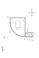
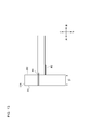
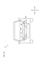
- 9 is a cross-sectional view showing a fixed portion, a radar, and a concealing portion cut along the line AA shown in FIG. It is a front view of the vehicle provided with the lamp for the left vehicle and the lamp for the right vehicle. It is a cross-sectional view in the vertical direction of the right vehicle lamp. It is a figure which shows the reflected radio wave reflected by the concealing part. It is sectional drawing in the horizontal direction which shows the 1st radar, the support member, and 1st concealment part.
- the "horizontal direction” of the vehicle 1 is referred to, but the “horizontal direction” is a direction perpendicular to the vertical direction (vertical direction) and includes a left-right direction and a front-rear direction. .. Further, in the present embodiment, the directions (horizontal direction, vertical direction, front-rear direction) set for the right-hand vehicle lighting tool 2R and the left-hand vehicle lighting tool 2L are the directions set for the vehicle 1 (horizontal direction, vertical direction, front-rear direction). It shall match the direction).
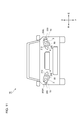
- FIG. 1 is a front view of a vehicle 1 provided with a left side vehicle lighting tool 2L and a right side vehicle lighting tool 2R.
- the left side vehicle lighting tool 2L is arranged on the left front side of the vehicle 1
- the right side vehicle lighting tool 2R is arranged on the right front side of the vehicle 1.
- Each of the left vehicle lighting fixture 2L and the right vehicle lighting fixture 2R includes a low beam lighting unit 3, a high beam lighting unit 4, a radar 5, and a concealing unit 6 that conceals the radar 5.
- the left side vehicle lighting equipment 2L and the right side vehicle lighting equipment 2R have the same configuration. Therefore, in the following description, the specific configuration of the right vehicle lamp 2R will be described with reference to FIG. Further, for convenience of explanation, the left side vehicle lighting equipment 2L and the right side vehicle lighting equipment 2R may be collectively referred to simply as "vehicle lighting equipment 2".
- the low beam lighting unit 3 is configured to emit a low beam light distribution pattern toward the front of the vehicle 1.
- the high beam lighting unit 4 is configured to emit a high beam light distribution pattern toward the front of the vehicle 1.
- the radar 5 is configured to acquire radar data indicating the surrounding environment of the vehicle 1 by emitting radio waves (for example, millimeter waves and microwaves) to the outside of the vehicle 1.
- the radar 5 is, for example, a millimeter wave radar or a microwave radar.
- the vehicle control unit vehicle-mounted computer (not shown) is configured to identify the surrounding environment of the vehicle 1 (particularly, information about an object existing outside the vehicle 1) based on the radar data output from the radar 5. ing.
- the radar 5 includes an antenna unit and a communication circuit unit (not shown).
- the antenna unit is configured to receive one or more transmitting antennas configured to radiate radio waves (for example, millimeter waves with a wavelength of 1 mm to 10 mm) into the air, and reflected radio waves reflected by an object. It is equipped with one or more receiving antennas.
- the antenna portion may be configured as a patch antenna (a metal pattern formed on a substrate). The radiated radio waves radiated from the transmitting antenna are reflected by an object such as another vehicle, and then the reflected radio waves from the object are received by the receiving antenna.
- the communication circuit unit includes a transmitting side RF (radio frequency) circuit, a receiving side RF circuit, and a signal processing circuit.
- the communication circuit section is configured as a monolithic microwave integrated circuit (MMIC).
- MMIC monolithic microwave integrated circuit
- the transmitting RF circuit is electrically connected to the transmitting antenna.
- the receiving RF circuit is electrically connected to the receiving antenna.
- the signal processing circuit is configured to generate radar data by processing a digital signal output from the receiving RF circuit.
- the antenna unit and the communication circuit unit may be housed in the case. Further, the antenna portion may be covered with a radome.
- the concealing unit 6 is arranged so as to face the radar 5 so as to conceal the radar 5 from the outside of the vehicle 1. Further, the concealing unit 6 is configured to transmit radio waves emitted from the radar 5.
- the concealing portion 6 may be made of, for example, an opaque resin member.
- the concealing portion 6 may be made of a resin member colored with a predetermined color such as black.
- the concealing portion 6 may be composed of a reflex reflector having a large number of fine prisms. In this case, since the light from the outside is totally reflected by the prism of the reflex reflector, the radar 5 can be concealed from the outside by the reflex reflector. In this way, the radar 5 can be concealed from the outside of the vehicle 1 by the concealing unit 6, and the design of the appearance of the right vehicle lighting tool 2R can be improved.
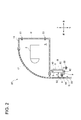
- FIG. 2 is a cross-sectional view of the right vehicle lamp 2R in the vertical direction (vertical direction).
- the right vehicle lamp 2R further includes a lamp housing 14, a lamp cover 12 that covers an opening of the lamp housing 14, and a support member 8.
- the lamp housing 14 may be formed of, for example, a metal member.
- the lamp cover 12 may be formed of, for example, a transparent resin member.
- the low beam lighting unit 3 and the high beam lighting unit 4 are arranged in the lamp chamber S formed by the lamp housing 14 and the lamp cover 12.
- an ADB lighting unit that emits an ADB (Adaptive Driving Beam) light distribution pattern having an irradiated area and a non-irradiated area is arranged in the lighting room S. You may. Further, the LiDAR unit and the camera may be arranged in the light room S.
- ADB Adaptive Driving Beam
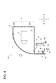
- the lamp housing 14 is provided with a mounting hole 142 (see FIG. 4).
- the lamp housing 14 is attached to the vehicle body B by a screw 23 inserted into the attachment hole 142.
- the lamp housing 14 may be provided with a lid portion (not shown). In this case, the operator can remove the screw 23 from the inside of the light chamber S by opening a lid (not shown).
- the support member 8 is a metal bracket, and is configured to support and fix the radar 5.
- the support member 8 is fixed to the vehicle body B via screws 22.
- the support member 8 has a lance 82 as an elastic engaging portion, and is configured to elastically engage with a positioning portion 9 described later via the lance 82.
- a spacer (not shown) is provided between the radar 5 and the support member 8. Since the air layer 40 is provided between the radar 5 and the support member 8 by the spacer, the external heat released from an external heat source such as an engine is suitably blocked by the air layer 40. In this way, it is possible to preferably prevent the radar 5 from being adversely affected by external heat.
- the support member 8 is arranged below the lamp housing 14. Since the radar 5 and the support member 8 are arranged outside the lighting chamber S, it is preferably prevented that the operation of the radar 5 is adversely affected by the heat generated from the low beam lighting unit 3 and the high beam lighting unit 4. ..
- the concealing portion 6 is integrally formed with the lamp cover 12 and extends downward from the lamp cover 12.
- the concealing portion 6 and the lamp cover 12 may be integrally formed by two-color molding using a mold.
- the concealing portion 6 may have a protruding portion 64 extending in the rear direction.
- the distance d between the concealing unit 6 and the radar 5 in the front-rear direction may be set to 20 mm or more and 100 mm or less in relation to the relative positional relationship between the radar 5 and the concealing unit 6.
- the distance d between the concealing unit 6 and the radar 5 is 20 mm or more, the reflected radio wave emitted from the radar 5 and reflected by the concealing unit 6 is sufficiently attenuated until it reaches the receiving antenna of the radar 5. .. Therefore, it is possible to avoid a situation in which the reflected radio wave received by the radar 5 adversely affects the radar data as a noise component.
- the distance between the concealing unit 6 and the radar 5 is 100 mm or less, it is possible to avoid a situation in which a part of the radio waves existing in the field of view of the radar 5 cannot pass through the concealing unit 6. That is, as a result of a part of the radio wave that cannot pass through the concealing portion 6 is reflected by the boundary portion between the concealing portion 6 and the lamp cover 12 and other optical components, the reflected radio wave adversely affects the radar data as a noise component. It can be avoided.
- FIG. 3 is a diagram showing reflected radio waves R1 and R2 reflected by the concealing unit 6.
- the thickness t of the concealing portion 6 shown in FIG. 3 is defined by the following equation (1).
- ⁇ is the wavelength of the radio wave emitted from the radar 5.
- ⁇ r is the relative permittivity of the concealing portion 6, and n is an integer of 1 or more.
- R2 and the reflected radio wave R1 reflected by the other surface 63 of the concealing portion 6 located on the opposite side of the one surface 62 weaken each other.
- the phase difference ⁇ between the reflected radio wave R2 and the reflected radio wave R1 is (2m + 1) ⁇ (m is an integer of zero or more)
- the reflected radio wave R1 and the reflected radio wave R2 weaken each other.
- the reflectance of the concealing unit 6 with respect to the radio waves emitted from the radar 5 can be lowered.
- the intensity of the reflected radio wave reflected by the concealing unit 6 is weakened, it is possible to avoid a situation in which the reflected radio wave is received by the radar 5 and adversely affects the radar data as a noise component.
- the wavelength ⁇ of the radio wave of the radar 5 is 3.922 mm
- the positioning portion 9 is arranged between the concealing portion 6 and the support member 8 in the front-rear direction.
- the positioning portion 9 is fixed to the concealing portion 6 and is configured to elastically engage with the support member 8.
- the positioning portion 9 has a fixing portion 93 fixed to the protruding portion 64 of the concealing portion 6 and an engaging hole portion 92 configured to engage with the lance 82 of the support member 8. When the lance 82 engages with the engaging hole portion 92, the support member 8 and the positioning portion 9 are elastically engaged. In this way, the position of the radar 5 with respect to the concealing portion 6 can be determined by the elastic engagement between the support member 8 and the positioning portion 9.
- the operator can release the elastic engagement between the lance 82 and the engaging hole portion 92 by applying a force upward to the lance 82 using a tool such as a flat-blade screwdriver (FIG. FIG. 4).
- a tool such as a flat-blade screwdriver (FIG. FIG. 4).
- the positioning portion 9 can be separated from the support member 8 relatively easily.
- the operator may insert a flat-blade screwdriver through the gap G between the concealing portion 6 and the front panel 20.
- the positioning portion 9 fixed to the concealing portion 6 is elastically engaged with the support member 8. Further, the support member 8 is fixed to the vehicle body B via the screw 22. Further, the concealing portion 6 is integrally formed with the lamp cover 12 and is fixed to the positioning portion 9.
- the elastic engagement between the positioning portion 9 and the support member 8 can be released by using a tool such as a flat-blade driver, so that the support member 8 and the positioning portion 9 are screwed or the like.
- the positioning portion 9 can be separated from the support member 8 relatively easily as compared with the case where the positioning portion 9 is fixed by.
- the components of the right vehicle lighting fixture 2R other than the support member 8 and the radar 5 are replaced with the vehicle body B while maintaining the state in which the support member 8 is fixed to the vehicle body B.
- the positioning portion 9 and the support member 8 are elastically engaged with each other.
- the positioning between the concealing unit 6 and the radar 5 can be easily performed. In this way, it is possible to improve the maintainability of the right-hand vehicle lamp 2R provided with the radar 5 and the concealing portion 6.
- the second embodiment of the present disclosure (hereinafter, simply referred to as “the present embodiment”) will be described with reference to the drawings.
- the dimensions of each member shown in this drawing may differ from the actual dimensions of each member for convenience of explanation. It should be noted that the members having the same reference numerals as the members already described in the first embodiment will not be repeatedly described.
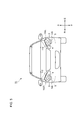
- FIG. 5 is a front view of the vehicle 1A provided with the left side vehicle light fixture 102L and the right side vehicle light fixture 102R.
- the left vehicle lighting fixture 102L is arranged on the left front side of the vehicle 1A
- the right vehicle lighting fixture 102R is arranged on the right front side of the vehicle 1A.
- Each of the left vehicle lighting fixture 102L and the right vehicle lighting fixture 102R includes a low beam lighting unit 3, a high beam lighting unit 4, a radar 5, and a concealing unit 106 that hides the radar 5.
- the left vehicle lamp 102L and the right vehicle lamp 102R have the same configuration. Therefore, in the following description, the specific configuration of the right vehicle lamp 102R will be described with reference to FIG. Further, for convenience of explanation, the left side vehicle lamp 102L and the right side vehicle lamp 102R may be collectively referred to simply as "vehicle lamp 102".
- the low beam lighting unit 3 is configured to emit a low beam light distribution pattern toward the front of the vehicle 1A.
- the high beam lighting unit 4 is configured to emit a high beam light distribution pattern toward the front of the vehicle 1A.
- the radar 5 is configured to acquire radar data indicating the surrounding environment of the vehicle 1A by emitting radio waves (for example, millimeter waves and microwaves) to the outside of the vehicle 1A.
- the radar 5 is, for example, a millimeter wave radar or a microwave radar.
- the vehicle control unit vehicle-mounted computer (not shown) is configured to identify the surrounding environment of the vehicle 1A (particularly, information on an object existing outside the vehicle 1A) based on the radar data output from the radar 5. ing.
- the concealment unit 106 is arranged so as to face the radar 5 so as to conceal the radar 5 from the outside of the vehicle 1A. Further, the concealing unit 106 is configured to transmit radio waves emitted from the radar 5.
- the concealing portion 106 may be composed of, for example, an opaque resin member.
- the concealing portion 106 may be composed of a resin member colored with a predetermined color such as black.
- the concealing unit 106 may be composed of a reflex reflector having a large number of fine prisms. In this case, since the light from the outside is totally reflected by the prism of the reflex reflector, the radar 5 can be concealed from the outside by the reflex reflector. In this way, the radar 5 can be concealed from the outside of the vehicle 1A by the concealing unit 106, and the design of the appearance of the right vehicle lamp 102R can be improved.
- FIG. 6 is a cross-sectional view of the right vehicle lamp 102R in the vertical direction (vertical direction).
- the right vehicle lamp 102R further includes a lamp housing 114, a lamp cover 112 that covers the opening of the lamp housing 114, and a support member 108.
- the lamp housing 114 may be formed of, for example, a metal member.
- the lamp cover 112 may be formed of, for example, a transparent resin member.
- the low beam lighting unit 3 and the high beam lighting unit 4 are arranged in the lamp chamber S1 formed by the lamp housing 114 and the lamp cover 112.
- the support member 108 is a metal bracket, and is configured to support and fix the radar 5.
- the support member 108 is fixed to the lamp housing 114 via a screw 122 (see FIG. 8).
- the support member 108 extends downward from the lamp housing 114. Further, since the radar 5 and the support member 108 are arranged outside the lighting chamber S1, it is preferably prevented that the operation of the radar 5 is adversely affected by the heat generated from the low beam lighting unit 3 and the high beam lighting unit 4. Will be done.
- the concealing portion 106 is integrally formed with the lamp cover 112 and extends downward from the lamp cover 112.
- the concealing portion 106 and the lamp cover 112 may be integrally formed by two-color molding using a mold.
- the horizontal field of view Fh (see FIG. 8) of the radar 5 may be, for example, in the range of 120 ° to 180 °.
- the field of view Fh of the radar 5 may be in the range of ⁇ 60 ° to ⁇ 90 ° with respect to the central axis of the radar 5.
- the vertical field of view Fv of the radar 5 may be in the range of, for example, 3 ° to 100 °.
- the field of view of the radar 5 is synonymous with the detection range of the radar 5.
- a margin angle region M is defined as an angle region adjacent to both ends of the field of view Fh of the radar 5.
- the intensity of the radio wave existing in the margin angle region M is sufficiently smaller than the intensity of the radio wave existing in the field view Fh, while the arrangement of the metal member that reflects the radio wave is prohibited in the margin angle region M.
- the margin angle region M may be, for example, in the range of 3 ° to 5 °.
- the distance d1 between the concealing unit 106 and the radar 5 in the front-rear direction may be set to 20 mm or more and 100 mm or less in relation to the relative positional relationship between the radar 5 and the concealing unit 106.
- the distance d1 between the concealing unit 106 and the radar 5 is 20 mm or more, the reflected radio wave emitted from the radar 5 and reflected by the concealing unit 106 is sufficiently attenuated until it reaches the receiving antenna of the radar 5. .. Therefore, it is possible to avoid a situation in which the reflected radio wave received by the radar 5 adversely affects the radar data as a noise component.
- the distance between the concealing unit 106 and the radar 5 is 100 mm or less, it is possible to avoid a situation in which a part of the radio waves existing in the field of view of the radar 5 cannot pass through the concealing unit 106. That is, as a result of a part of the radio wave that cannot pass through the concealing portion 106 being reflected by the boundary portion between the concealing portion 106 and the lamp cover 112 and other optical components, the reflected radio wave adversely affects the radar data as a noise component. It can be avoided.
- FIG. 7 is a diagram showing reflected radio waves R1 and R2 reflected by the concealing unit 106.
- the thickness t1 of the concealing portion 106 shown in FIG. 7 is defined by the following equation (2).
- ⁇ is the wavelength of the radio wave emitted from the radar 5.
- ⁇ r is the relative permittivity of the concealing portion 106, and n is an integer of 1 or more.
- R2 and the reflected radio wave R1 reflected by the other surface 163 of the concealing portion 106 located on the opposite side of the one surface 162 weaken each other.
- the phase difference ⁇ between the reflected radio wave R2 and the reflected radio wave R1 is (2m + 1) ⁇ (m is an integer of zero or more)
- the reflected radio wave R1 and the reflected radio wave R2 weaken each other.
- the reflectance of the concealing unit 106 with respect to the radio waves emitted from the radar 5 can be lowered.
- the intensity of the reflected radio wave reflected by the concealing unit 106 is weakened, it is possible to avoid a situation in which the reflected radio wave is received by the radar 5 and adversely affects the radar data as a noise component.
- the wavelength ⁇ of the radio wave of the radar 5 is 3.922 mm
- FIG. 8 is a horizontal sectional view showing the radar 5, the support member 108, and the concealing portion 106.
- the support member 108 is fixed to the lamp housing 114 via a screw 122 which is a fixing means.
- the radar 5 is supported and fixed by a lance 23 provided on the support member 108.
- the radar 5 has a front surface 51, a rear surface 52 located on the opposite side of the front surface 51, and a side surface 53 located between the front surface 51 and the rear surface 52.
- the radio wave emitted from the transmitting antenna of the radar 5 is radiated into the air through the front surface 51.
- Spacers 120a and 120b are provided between the radar 5 and the support member 108.
- the thermal conductivity of the spacers 120a and 120b may be lower than the thermal conductivity of the support member 108.
- the spacer 120a faces the spacer 120b in the left-right direction.
- Each of the spacers 120a and 120b is in contact with the rear surface 52 and the side surface 53 of the radar 5. Since the two spacers 120a and 120b separated from each other are provided between the radar 5 and the support member 108 in this way, the air layer 30 (of the heat insulating layer) is provided between the rear surface 52 of the radar 5 and the support member 108. An example) is formed.
- the heat radiated from the engine (not shown) arranged behind the support member 108 by the air layer 30 having a lower thermal conductivity than the support member 108 is transmitted to the rear surface of the radar 5 via the support member 108. It becomes difficult to transmit to 52. Therefore, it is possible to preferably prevent the operating performance of the radar 5 (particularly, the communication circuit unit) from being deteriorated by the radiant heat from the engine. Therefore, the air layer 30 can ensure the reliability of the radar 5 against radiant heat from the outside.
- the radar 5 and the concealing unit 106 are separated by a distance d1 (see FIG. 6) in the front-rear direction.
- the relative positional relationship between the radar 5 and the concealing unit 106 is determined by the positioning units 109a and 109b.
- the positioning portion 109a is configured to determine the position of the support member 108 with respect to the concealing portion 106 by engaging the recess 192a provided in the positioning portion 109a with the protrusion 18a provided in the support member 108. ing.
- the positioning portion 109b engages with the protruding portion 18b provided in the support member 108, so that the positioning portion 109b determines the position of the support member 108 with respect to the concealing portion 106.
- the positioning portions 109a and 109b are integrally formed with the concealing portion 106 and are arranged between the concealing portion 106 and the radar 5.
- the positioning unit 109a faces the positioning unit 109b in the left-right direction via the radar 5.
- the radar 5 is also positioned with respect to the vehicle 1A when the positioning of the vehicle lamp 102 with respect to the vehicle 1A is completed. Complete at the same time. Therefore, the positioning units 109a and 109b can relatively easily and reliably position the radar 5 with respect to the vehicle 1A.
- FIG. 9 is an enlarged front view of the right vehicle lamp 102R.
- FIG. 10 is a cross-sectional view showing the fixing portions 7a and 7b, the radar 5 and the concealing portion 106 cut along the line AA shown in FIG. It is assumed that the AA line is a line parallel to the virtual line L described later.
- the lamp housing 114 has four fixing portions 7a to 7d for fixing the right vehicle lighting tool 102R to the vehicle 1A.
- Each of the four fixing portions 7a to 7d may include, for example, a fastening means such as a screw and a hole (for example, a screw hole) into which the fastening means is inserted.
- the right vehicle lighting fixture 102R is fixed to the vehicle body panel of the vehicle 1A via four fixing portions 7a to 7d.
- the fixing portions 7a and 7b are provided so as to project downward from the lower end of the lamp housing 114.
- the fixing portions 7c and 7d are provided so as to project upward from the upper end of the lamp housing 114.
- the radar 5 and the concealing portion 106 are arranged between the fixed portion 7a (an example of the first fixed portion) and the fixed portion 7b (an example of the second fixed portion) in the left-right direction.
- the virtual line passing through the fixed portion 7a and the fixed portion 7b is defined as the virtual line L.
- the fixing portions 7a and 7b are provided in the lamp housing 114 so that the concealing portion 106 and the radar 5 at least partially overlap the virtual line L when the right vehicle lamp 102R is viewed from the front. ..
- the radar 5 is arranged between the fixed portion 7a and the fixed portion 7b in the left-right direction, even if the lamp housing 114 vibrates according to the traveling of the vehicle 1A, the lamp housing 114 The transmission of vibration to the radar 5 can be suitably suppressed by the fixing portions 7a and 7b. As described above, since it is preferably prevented that the operating performance of the radar 5 is adversely affected by the vibration of the radar 5, the reliability of the radar 5 can be ensured.
- the radar 5 overlaps at least partially on the virtual line L, so that the lamp housing 114 changes according to the traveling of the vehicle 1A. Even in the case of vibration, the transmission of the vibration of the lamp housing 114 to the radar 5 can be suitably suppressed by the fixing portions 7a and 7b.
- the radar 5 is arranged between the virtual line L and the concealing portion 106 in the front-rear direction or the optical axis direction of the radar 5 (not shown). Therefore, it is possible to preferably prevent the fixed portions 7a and 7b from being located in the field of view Fh and the margin region M of the radar 5. As described above, the situation where the radio waves emitted from the radar 5 are reflected by the fixed portions 7a and 7b and the situation where the reflected radio waves reflected by the fixed portions 7a and 7b are received by the radar 5 can be preferably prevented. Therefore, it is possible to prevent the reflected radio waves reflected by the fixed portions 7a and 7b from adversely affecting the radar data as noise components.
- the present embodiment a third embodiment of the present disclosure (hereinafter, simply referred to as “the present embodiment”) will be described with reference to the drawings.
- the dimensions of each member shown in this drawing may differ from the actual dimensions of each member for convenience of explanation. It should be noted that the description of the members having the same reference numerals as the members already described in the first embodiment and the second embodiment will not be repeated.
- FIG. 11 is a front view of the vehicle 1B provided with the left vehicle lighting fixture 202L and the right vehicle lighting fixture 202R.
- the left vehicle lighting fixture 202L is arranged on the left front side of the vehicle 1B
- the right vehicle lighting fixture 202R is arranged on the right front side of the vehicle 1B.
- Each of the left vehicle lighting fixture 202L and the right vehicle lighting fixture 202R has a low beam lighting unit 3, a high beam lighting unit 4, a first radar 50, a first concealing unit 206 that conceals the first radar 50, and a first It includes two radars 70 and a second concealing unit 209 that conceals the second radar 70.
- the left side vehicle lighting fixture 202L and the right side vehicle lighting fixture 202R have the same configuration. Therefore, in the following description, the specific configuration of the right vehicle lamp 202R will be described with reference to FIG. Further, for convenience of explanation, the left side vehicle lighting fixture 202L and the right side vehicle lighting fixture 202R may be collectively referred to simply as "vehicle lighting fixture 202".
- the first radar 50 is configured to acquire radar data indicating the surrounding environment of the vehicle 1B by emitting radio waves (for example, millimeter waves or microwaves) toward the outside of the vehicle 1B.
- the first radar 50 is, for example, a millimeter-wave radar or a microwave radar for a long distance.
- the first radar 50 is arranged closer to the inside than the second radar 70 in the left-right direction (vehicle width direction), and is configured to detect an object in the front region of the vehicle 1B.
- the first radar 50 includes an antenna unit and a communication circuit unit (not shown).
- the antenna unit is configured to receive one or more transmitting antennas configured to radiate radio waves (for example, millimeter waves with a wavelength of 1 mm to 10 mm) into the air, and reflected radio waves reflected by an object. It is equipped with one or more receiving antennas.
- the antenna portion may be configured as a patch antenna (a metal pattern formed on a substrate). The radiated radio waves radiated from the transmitting antenna are reflected by an object such as another vehicle, and then the reflected radio waves from the object are received by the receiving antenna.
- the antenna unit and the communication circuit unit may be housed in the case. Further, the antenna portion may be covered with a radome.
- the first concealment unit 206 is arranged so as to face the first radar 50 so as to conceal the first radar 50 from the outside of the vehicle 1B. Further, the first concealing portion 206 is integrally formed with the lamp cover 212 so as to extend from the lamp cover 212 in the vertical direction.
- the first concealment unit 206 is configured to transmit radio waves emitted from the first radar 50.
- the first concealing portion 206 may be made of, for example, an opaque resin member.
- the first concealing portion 206 may be made of a resin member colored with a predetermined color such as black.
- the first concealing unit 206 may be composed of a reflex reflector having a large number of fine prisms. In this case, since the light from the outside is totally reflected by the prism of the reflex reflector, the first radar 50 can be concealed from the outside by the reflex reflector. In this way, the first radar 50 can be concealed from the outside of the vehicle 1B by the first concealing unit 206, and the design of the appearance of the right vehicle lamp 202R can be improved.
- the second radar 70 is configured to acquire radar data indicating the surrounding environment of the vehicle 1B by emitting radio waves (for example, millimeter waves or microwaves) toward the outside of the vehicle 1B.
- the second radar 70 is, for example, a millimeter-wave radar or a microwave radar for a short distance.
- the second radar 70 is arranged outward in the left-right direction, and is configured to detect an object in the diagonally right front region of the vehicle 1B.
- the vehicle control unit (vehicle-mounted computer) (not shown) exists in the surrounding environment of the vehicle 1B (particularly, outside the vehicle 1B) based on the radar data output from the first radar 50 and the radar data output from the second radar 70. It is configured to identify information about the object to be used.
- the wavelength of the radio wave emitted from the second radar 70 may be the same as or different from the wavelength of the radio wave emitted from the first radar 50.
- the first radar 50 functions as a long-range radar, while the second radar 70 functions as a short-range radar. Therefore, the detection distance of the first radar 50 is longer than the detection distance of the second radar 70. Further, the horizontal field of view Fa of the first radar 50 is narrower than the horizontal field of view Fb of the second radar 70 (see FIG. 15).
- the second radar 70 includes an antenna unit and a communication circuit unit (not shown).
- the antenna unit is configured to receive one or more transmitting antennas configured to radiate radio waves (for example, millimeter waves with a wavelength of 1 mm to 10 mm) into the air, and reflected radio waves reflected by an object. It is equipped with one or more receiving antennas.
- the antenna portion may be configured as a patch antenna.
- the second concealment unit 209 is arranged so as to face the second radar 70 so as to conceal the second radar 70 from the outside of the vehicle 1B. Further, the second concealing portion 209 is separated from the first concealing portion 206, and is integrally formed with the lamp cover 212 so as to extend from the lamp cover 212 in the left-right direction.
- the second concealment unit 209 is configured to transmit radio waves emitted from the second radar 70.
- the second concealing portion 209 may be composed of, for example, an opaque resin member.
- the second concealing portion 209 may be composed of a resin member colored with a predetermined color such as black.
- the second concealing unit 209 may be configured by a reflex reflector. In this way, the second radar 70 can be concealed from the outside of the vehicle 1B by the second concealing unit 209, and the design of the appearance of the right vehicle lamp 202R can be improved.
- FIG. 12 is a cross-sectional view of the right vehicle lamp 202R in the vertical direction (vertical direction). As shown in FIG. 12, the right vehicle lamp 202R further includes a lamp housing 214, a lamp cover 212 that covers the opening of the lamp housing 214, and a support member 208.
- the lamp housing 214 may be formed of, for example, a metal member.
- the lamp cover 212 may be formed of, for example, a transparent resin member.
- the low beam lighting unit 3 and the high beam lighting unit 4 are arranged in the lamp chamber S2 formed by the lamp housing 214 and the lamp cover 212.
- the support member 208 is a metal bracket and is configured to support and fix the first radar 50.
- the support member 208 is fixed to the lamp housing 214 via a screw 122 (see FIG. 14).
- the support member 208 extends downward from the lamp housing 214. Further, since the first radar 50 and the support member 208 are arranged outside the lighting chamber S2, the operation of the first radar 50 is adversely affected by the heat generated from the low beam lighting unit 3 and the high beam lighting unit 4. Is preferably prevented.
- the first concealing portion 206 is integrally formed with the lamp cover 212 and extends downward from the lamp cover 212.
- the first concealing portion 206 and the lamp cover 212 may be integrally formed by two-color molding using a mold.
- the first concealing portion 206 and the lamp cover 212 are integrally formed by two-color molding, the first concealing portion 206 is located at or near the boundary portion B1 between the first concealing portion 206 and the lamp cover 212. And a protruding portion is formed on the lamp cover 212.
- the first concealing portion 206 and the first concealing portion 206 are arranged so that the boundary portion B between the first concealing portion 206 and the lamp cover 212 is arranged outside the vertical field of view Fa of the first radar 50. The relative positional relationship with the radar 50 is adjusted.
- the boundary portion B1 between the first concealing portion 206 and the lamp cover 212 is arranged outside the field of view Fa of the first radar 50. Therefore, as a result of the radio waves existing in the field of view Fa of the first radar 50 being reflected by the protruding portion formed at the boundary portion B1, the reflected radio waves are incident on the receiving antenna of the first radar 50, and the radar data is obtained. It is possible to avoid adverse situations. Therefore, the first radar 50 can be concealed from the outside of the vehicle 1B while ensuring the reliability of the radar data acquired by the first radar 50 mounted on the right vehicle lighting fixture 202R.
- the horizontal field of view Fa (see FIG. 15) of the first radar 50 that functions as a long-range radar may be, for example, in the range of ⁇ 5 ° to ⁇ 10 °.
- the field of view Fa in the vertical direction of the first radar 50 may be, for example, in the range of ⁇ 2 ° to ⁇ 8 °.
- the field of view of the first radar 50 is synonymous with the detection range of the first radar 50.
- the detection distance of the first radar 50 which functions as a long-distance radar, is, for example, 250 m.
- the detection distance of the radar means the limit detection distance at which the radar can detect an object. If the object is within the radar's detection distance, the radar can detect the object, while if the object is farther than the radar's detection distance, the radar will detect the object. Can not do it.
- the distance d2 between the first concealing unit 206 and the first radar 50 in the front-rear direction is 20 mm or more and 100 mm or less. May be set to.
- the distance d2 between the first concealing unit 206 and the first radar 50 is 20 mm or more
- the reflected radio wave emitted from the first radar 50 and reflected by the first concealing unit 206 is the first radar 50. It is sufficiently attenuated to reach the receiving antenna. Therefore, it is possible to avoid a situation in which the reflected radio wave received by the first radar 50 adversely affects the radar data as a noise component.
- the distance between the first concealment unit 206 and the first radar 50 is 100 mm or less, a situation in which a part of the radio waves existing in the field of view of the first radar 50 cannot pass through the first concealment unit 206. It can be avoided. That is, as a result of a part of the radio wave that cannot pass through the first concealing unit 206 is reflected by the boundary portion B1 between the first concealing unit 206 and the lamp cover 212 and other optical components, the reflected radio wave is converted into radar data as a noise component. It is possible to avoid adverse situations.
- FIG. 13 is a diagram showing reflected radio waves R1 and R2 reflected by the first concealing unit 206.
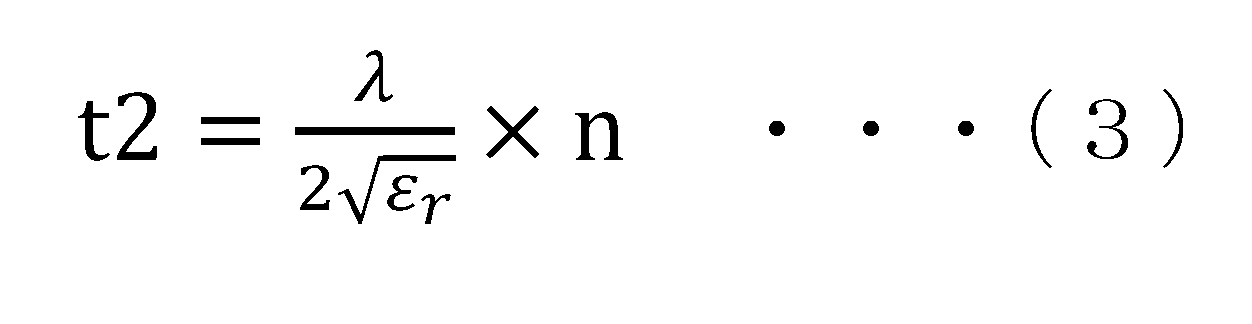
- the thickness t2 of the first concealing portion 206 shown in FIG. 13 is defined by the following equation (3).
- ⁇ is the wavelength of the radio wave emitted from the first radar 50.
- ⁇ r is the relative permittivity of the first concealing portion 206, and n is an integer of 1 or more.
- the thickness t2 of the first concealing portion 206 is set to the thickness specified in the above formula (3), one surface 262 of the first concealing portion 206 facing the first radar 50 is set.
- the reflected radio wave R2 reflected by the above and the reflected radio wave R1 reflected by the other surface 263 of the first concealing portion 206 located on the opposite side of the one surface 262 are weakened against each other.
- the phase difference ⁇ between the reflected radio wave R2 and the reflected radio wave R1 is (2m + 1) ⁇ (m is an integer of zero or more), the reflected radio wave R1 and the reflected radio wave R2 weaken each other.
- the reflectance of the first concealing unit 206 with respect to the radio waves emitted from the first radar 50 can be lowered. Therefore, since the intensity of the reflected radio wave reflected by the first concealing unit 206 is weakened, it is possible to avoid a situation in which the reflected radio wave is received by the first radar 50 and adversely affects the radar data as a noise component. ..
- the wavelength ⁇ of the radio wave of the first radar 50 is 3.922 mm
- the relative permittivity ⁇ r of the first concealing portion 206 2
- n 1
- the thickness t2 of the first concealing portion 206 is 1. It becomes 386 mm.
- FIG. 14 is a horizontal sectional view showing the first radar 50, the support member 208, and the first concealing portion 206.
- the support member 208 is fixed to the lamp housing 214 via a screw 122 which is a fixing means.
- the first radar 50 is supported and fixed by a lance 223 provided on the support member 208.
- the first radar 50 has a front surface 51, a rear surface 52 located on the side opposite to the front surface 51, and a side surface 53 located between the front surface 51 and the rear surface 52.
- the radio wave emitted from the transmitting antenna of the first radar 50 is radiated into the air through the front surface 51.
- Spacers 220a and 220b are provided between the first radar 50 and the support member 208.
- the thermal conductivity of the spacers 220a and 220b may be lower than the thermal conductivity of the support member 208.
- the spacer 220a faces the spacer 220b in the left-right direction.
- Each of the spacers 220a and 220b is in contact with the rear surface 52 and the side surface 53 of the first radar 50. Since the two spacers 220a and 220b separated from each other are provided between the first radar 50 and the support member 208 in this way, the air layer 230 is located between the rear surface 52 of the first radar 50 and the support member 208. (An example of a heat insulating layer) is formed.
- the heat radiated from the engine (not shown) arranged behind the support member 208 by the air layer 230 having a lower thermal conductivity than the support member 208 is transmitted through the support member 208 to the first radar 50. It becomes difficult to transmit to the rear surface 52. Therefore, it is possible to preferably prevent the operating performance of the first radar 50 (particularly, the communication circuit unit) from being deteriorated by the radiant heat from the engine. Therefore, the air layer 230 can ensure the reliability of the first radar 50 against radiant heat from the outside.
- the first radar 50 and the first concealing unit 206 are separated by a distance d2 (see FIG. 12) in the front-rear direction.
- the relative positional relationship between the first radar 50 and the first concealing unit 206 is determined by the positioning units 210a and 210b.
- the recess 292a provided in the positioning portion 210a engages with the protrusion 218a provided in the support member 208 so that the positioning portion 210a determines the position of the support member 208 with respect to the first concealment portion 206. It is configured.
- the positioning portion 210b engages with the protrusion 218b provided in the support member 208 so that the positioning portion 210b determines the position of the support member 208 with respect to the first concealment portion 206. It is configured in. Further, the positioning portions 210a and 210b are integrally formed with the first concealing portion 206 and are arranged between the first concealing portion 206 and the first radar 50. The positioning unit 210a faces the positioning unit 210b in the left-right direction via the first radar 50.
- the positions of the support member 208 with respect to the first concealing portion 206 are determined by the two positioning portions 210a and 210b. Therefore, when the positioning of the vehicle lamp 202 with respect to the vehicle 1B is completed, the first radar with respect to the vehicle 1B is completed. Positioning of 50 is also completed at the same time. Therefore, the positioning units 210a and 210b can relatively easily and reliably position the first radar 50 with respect to the vehicle 1B.
- the second radar 70 and the second concealment unit 209 are the same as the first radar 50 and the first concealment unit 206.
- the second concealing portion 209 and the lamp cover 212 may be integrally formed by two-color molding using a mold.
- the horizontal field of view Fb (see FIG. 15) of the second radar 70 that functions as a short-range radar may be, for example, in the range of ⁇ 50 ° to ⁇ 85 °.
- the vertical field of view Fb of the second radar 70 may be, for example, in the range of ⁇ 5 ° to ⁇ 10 °.
- the detection distance of the second radar 70, which functions as a short-range radar is, for example, 50 m.
- the distance d3 between the second concealing unit 209 and the second radar 70 in the front-rear direction is 20 mm or more and 100 mm or less. May be set to.
- the distance d3 between the second concealment unit 209 and the second radar 70 is 20 mm or more
- the reflected radio wave emitted from the second radar 70 and reflected by the second concealment unit 209 is the second radar 70. It is sufficiently attenuated to reach the receiving antenna. Therefore, it is possible to avoid a situation in which the reflected radio wave received by the second radar 70 adversely affects the radar data as a noise component.
- the distance between the second concealment unit 209 and the second radar 70 is 100 mm or less, a situation in which a part of the radio waves existing in the field of view of the second radar 70 cannot pass through the second concealment unit 209. It can be avoided. That is, as a result of a part of the radio wave that cannot pass through the second concealing unit 209 is reflected by the boundary portion between the second concealing unit 209 and the lamp cover 212 and other optical components, the reflected radio wave adversely affects the radar data as a noise component. It is possible to avoid the situation of giving.
- the thickness t3 of the second concealing portion 209 is defined by the following equation (4).
- ⁇ is the wavelength of the radio wave emitted from the second radar 70.
- ⁇ r is the relative permittivity of the second concealing portion 209, and n is an integer of 1 or more.
- the thickness t3 of the second concealing portion 209 is set to the thickness specified in the above formula (4), one surface of the second concealing portion 209 facing the second radar 70 The reflected reflected radio wave and the reflected radio wave reflected on the other surface of the second concealing portion 209 located on the opposite side of the one surface weaken each other.
- the reflectance of the second concealing unit 209 with respect to the radio waves emitted from the second radar 70 can be lowered. Therefore, since the intensity of the reflected radio wave reflected by the second concealing unit 209 is weakened, it is possible to avoid a situation in which the reflected radio wave is received by the second radar 70 and adversely affects the radar data as a noise component. ..
- the wavelength of the radio wave emitted from the second radar 70 is the same as the wavelength of the radio wave emitted from the first radar 50, and the resin material constituting the second concealment unit 209 constitutes the first concealment unit 206.
- the thickness t2 of the first concealing portion 206 and the thickness t3 of the second concealing portion 209 may be the same.
- the second radar 70 is supported and fixed by a support member (not shown) in the same manner as the structure shown in FIG. Further, the support member for supporting and fixing the second radar 70 is fixed to the lamp housing 214 via a fixing means such as a screw. Further, a positioning unit (not shown) for defining the relative positional relationship between the second radar 70 and the second concealing unit 209 is integrally formed with the second concealing unit 209, and the second It is arranged between the concealment unit 209 and the second radar 70.
- the operation of the second radar 70 may be adversely affected by the heat generated from the low beam lighting unit 3 and the high beam lighting unit 4. It is preferably prevented.
- the field fa of the first radar 50 mounted on the left vehicle lamp 202L, the field Fb of the second radar 70 mounted on the left vehicle lamp 202L, and the right vehicle lamp 202R The field fa of the mounted first radar 50 and the field Fb of the second radar 70 mounted on the right vehicle lamp 202R will be described below.
- the fields of view Fa and Fb shown in FIG. 15 are the fields of view (detection area) of the radar in the horizontal direction.
- the field of view Fa of the first radar 50 is narrower than the field of view Fb of the second radar 70, while the detection distance of the first radar 50 is longer than the detection distance of the second radar 70.
- the two first radars 50 mounted on the left vehicle lighting fixture 202L and the right vehicle lighting fixture 202R can detect an object existing in the front region of the vehicle 1B.
- the second radar 70 mounted on the left vehicle lighting 202L can detect an object existing in the diagonally left front region of the vehicle 1B
- the second radar 70 mounted on the right vehicle lighting 202R can detect an object.
- An object existing in the diagonally right front region of the vehicle 1B can be detected. In this way, by using the four radars mounted on the vehicle 1B, it is possible to specify the surrounding environment information of the vehicle 1B.
- the first radar 50 is provided by the first concealing unit 206 integrally formed with the lamp cover 212.
- the second radar 70 can be concealed from the outside of the vehicle 1B by the second concealing portion 209 integrally formed with the lamp cover 212.
- the work process for separately attaching the two concealing portions 206 and 209 to the right vehicle lamp 202R is omitted. Therefore, the two radars 50 and 70 mounted on the right vehicle lamp 202R can be concealed from the outside of the vehicle 1B without increasing the number of steps of assembling the right vehicle lamp 202R.
- a vehicle lamp equipped with two radars and two concealing parts has been described, but the number of radars and concealing parts is not particularly limited. For example, three or more radars and three or more concealment units may be mounted on the vehicle lamp.
- FIG. 16 is a front view of the vehicle 1C provided with the vehicle lamp 2M according to the modified example.
- FIG. 17 is a schematic view showing the fields of view Fc to Fi of the radars 151 to 156 mounted on the vehicle lamp 2M.
- the vehicle lamp 2M is mounted on the front side of the vehicle 1C.
- the vehicle lamp 2M is a long vehicle lamp extending in the left-right direction, and has the functions of both the left vehicle lamp and the right vehicle lamp.
- a low beam lighting unit 3b and a high beam lighting unit 4b are provided on the left side of the vehicle lighting device 2M, and a low beam lighting unit 3a and a high beam lighting unit 4a are provided on the right side of the vehicle lighting device 2M.
- the two low beam lighting units 3a and 3b and the high beam lighting units 4a and 4b are arranged in a lamp chamber formed by a lamp housing and a lamp cover 212a (not shown).
- Each of the radars 151 to 156 is configured to acquire radar data indicating the surrounding environment of the vehicle 1C by emitting radio waves (for example, millimeter waves and microwaves) toward the outside of the vehicle 1C. Radars 151 to 156 are arranged side by side in the left-right direction.
- the radar 151 is a short-range radar and is configured to detect an obliquely right front region of the vehicle 1C.
- the radar 152 is a medium-range radar and is configured to detect the front area of the vehicle 1C.
- the radar 153 is a long-range radar and is configured to detect the front area of the vehicle 1C.
- the radar 156 is a short-range radar and is configured to detect the diagonally left front region of the vehicle 1C.
- the radar 155 is a medium-range radar and is configured to detect the front area of the vehicle 1C.
- the radar 154 is a long-range radar and is configured to detect the front area of the vehicle 1C.
- the size relationship between the field of view Fc of the radar 151, the field of view Fd of the radar 152, and the field of view Fe of the radar 153 is Fc> Fd> Fe.
- the magnitude relationship between the detection distance Dc of the radar 151, the detection distance Dd of the radar 152, and the detection distance De of the radar 153 is De> Dd> Dc.
- the size relationship between the field of view Fi of the radar 156, the field of view Fh of the radar 155, and the field of view Fg of the radar 154 is Fi> Fh> Fg.
- the magnitude relationship between the detection distance Di of the radar 156, the detection distance Dh of the radar 155, and the detection distance Dg of the radar 154 is Dg> Dh> Di.
- the horizontal fields of view Fd and Fh of the radars 152 and 155 functioning as medium-range radars may be, for example, in the range of ⁇ 50 ° to ⁇ 85 °.
- the vertical fields of view Fd and Fh of the radars 152 and 155 may be, for example, in the range of ⁇ 5 ° to ⁇ 10 °.
- the detection distance of the radars 152 and 155 that function as medium-range radars is, for example, 100 m.
- the concealing unit 206a is arranged so as to face the radars 151 to 156 so as to conceal the radars 151 to 156 from the outside of the vehicle 1C.
- the concealing portion 206a is integrally formed with the lamp cover 212a and extends downward from the lamp cover 212a.
- the concealing portion 206a and the lamp cover 212a may be integrally formed by two-color molding using a mold.
- the concealing unit 206a is configured to transmit radio waves emitted from each of the radars 151 to 156.
- the concealing portion 206a may be made of, for example, an opaque resin member.
- the concealing portion 206a may be made of a resin member colored with a predetermined color such as black.
- the concealing portion 206a may be configured by a reflex reflector. In this way, each of the radars 151 to 156 can be concealed from the outside of the vehicle 1C by the concealing unit 206a, and the design of the appearance of the vehicle lamp 2M can be improved.
- the distance d3 between each of the radars 151 to 156 and the concealing portion 206a in the front-rear direction is 20 mm or more and 100 mm or less. May be set to.
- the thickness t4 of the concealing portion 206a may be defined by the following equation (5).
- ⁇ is the wavelength of the radio wave emitted from the radars 151 to 156.
- ⁇ r is the relative permittivity of the concealing portion 206a
- n is an integer of 1 or more.
- each of the radars 151 to 156 is supported and fixed by a support member (not shown). Further, the support member for supporting and fixing the radar is fixed to the lamp housing via a fixing means such as a screw.
- each of the radars 151 to 156 is arranged outside the lighting room, it is preferably prevented that the operation of the radars 151 to 156 is adversely affected by the heat generated from the low beam lighting unit and the high beam lighting unit. ..
- the radars 151 to 156 arranged side by side in the left-right direction can be concealed from the outside of the vehicle 1C by the single concealing portion 206a integrally formed with the lamp cover 212a.
- the six radars mounted on the vehicle lighting equipment 2M can be concealed from the outside of the vehicle 1C without increasing the number of steps of assembling the vehicle lighting equipment 2M.
Landscapes
- Engineering & Computer Science (AREA)
- Radar, Positioning & Navigation (AREA)
- Remote Sensing (AREA)
- Physics & Mathematics (AREA)
- Computer Networks & Wireless Communication (AREA)
- General Physics & Mathematics (AREA)
- Electromagnetism (AREA)
- Mechanical Engineering (AREA)
- General Engineering & Computer Science (AREA)
- Radar Systems Or Details Thereof (AREA)
- Lighting Device Outwards From Vehicle And Optical Signal (AREA)
- Arrangement Of Elements, Cooling, Sealing, Or The Like Of Lighting Devices (AREA)
Abstract
Description
ランプハウジングと、
前記ランプハウジングの開口部を覆うランプカバーと、
前記ランプハウジングと前記ランプカバーとによって形成された灯室内に配置された照明ユニットと、
電波を車両の外部に向けて出射することで前記車両の周辺環境を示すレーダデータを取得するように構成されたレーダと、
前記レーダを前記車両の外部から隠蔽するように前記レーダに対向するように配置され、前記レーダから出射された電波を通過させるように構成された隠蔽部と、
車体に固定され、前記レーダを支持及び固定するように構成された支持部材と、
前記隠蔽部と前記支持部材との間に配置され、前記隠蔽部に対する前記レーダの位置を決定するように構成された位置決め部と、を備える。
前記隠蔽部は、前記ランプカバーと一体的に形成される。
前記位置決め部は、前記隠蔽部に固定されると共に、前記支持部材と弾性的に係合するように構成される。
前記車両用灯具を前記車両に固定するための第1固定部と第2固定部とを有するランプハウジングと、
前記ランプハウジングの開口部を覆うランプカバーと、
前記ランプハウジングと前記ランプカバーとによって形成された灯室内に配置された照明ユニットと、
電波を前記車両の外部に向けて出射することで前記車両の周辺環境を示すレーダデータを取得するように構成されたレーダと、
前記レーダを前記車両の外部から隠蔽するように前記レーダに対向するように配置され、前記レーダから出射された電波を通過させるように構成された隠蔽部と、
前記レーダを支持するように構成され、前記ランプハウジングに固定された支持部材と、を備える。
前記隠蔽部は、前記ランプカバーと一体的に形成される。
前記レーダは、前記車両用灯具の左右方向において、前記第1固定部と前記第2固定部との間に配置されている。
ランプハウジングと、
前記ランプハウジングの開口部を覆うランプカバーと、
前記ランプハウジングと前記ランプカバーとによって形成された灯室内に配置された照明ユニットと、
電波を車両の外部に向けて出射することで前記車両の周辺環境を示す第1レーダデータを取得するように構成された第1レーダと、
電波を前記車両の外部に向けて出射することで前記車両の周辺環境を示す第2レーダデータを取得するように構成された第2レーダと、
前記第1レーダ及び前記第2レーダを前記車両の外部から隠蔽すると共に、前記第1レーダ及び前記第2レーダから出射された電波を通過させるように構成された隠蔽部と、を備える。
前記隠蔽部は、前記ランプカバーと一体的に形成されている。
以下、本開示の第1実施形態(以下、単に「本実施形態」という。)について図面を参照しながら説明する。本図面に示された各部材の寸法は、説明の便宜上、実際の各部材の寸法とは異なる場合がある。

以下、本開示の第2実施形態(以下、単に「本実施形態」という。)について図面を参照しながら説明する。本図面に示された各部材の寸法は、説明の便宜上、実際の各部材の寸法とは異なる場合がある。尚、第1実施形態で既に説明された部材と同一の符号が付された部材については繰り返し説明を行わない。

以下、本開示の第3実施形態(以下、単に「本実施形態」という。)について図面を参照しながら説明する。本図面に示された各部材の寸法は、説明の便宜上、実際の各部材の寸法とは異なる場合がある。尚、第1実施形態及び第2実施形態において既に説明された部材と同一の符号が付された部材についての説明は繰り返し行わない。

次に、図16及び図17を参照して変形例に係る車両用灯具2Mについて以下に説明する。図16は、変形例に係る車両用灯具2Mを備えた車両1Cの正面図である。図17は、車両用灯具2Mに搭載されたレーダ151~156の視野Fc~Fiを示す模式図である。

Claims (22)
- ランプハウジングと、
前記ランプハウジングの開口部を覆うランプカバーと、
前記ランプハウジングと前記ランプカバーとによって形成された灯室内に配置された照明ユニットと、
電波を車両の外部に向けて出射することで前記車両の周辺環境を示すレーダデータを取得するように構成されたレーダと、
前記レーダを前記車両の外部から隠蔽するように前記レーダに対向するように配置され、前記レーダから出射された電波を通過させるように構成された隠蔽部と、
車体に固定され、前記レーダを支持及び固定するように構成された支持部材と、
前記隠蔽部と前記支持部材との間に配置され、前記隠蔽部に対する前記レーダの位置を決定するように構成された位置決め部と、を備え、
前記隠蔽部は、前記ランプカバーと一体的に形成され、
前記位置決め部は、前記隠蔽部に固定されると共に、前記支持部材と弾性的に係合するように構成される、車両用灯具。 - 前記レーダは、前記灯室外に配置されている、請求項1に記載の車両用灯具。
- 前記隠蔽部の厚さtは、以下式により規定されている、請求項1又は2に記載の車両用灯具。
t=λ/2εr 1/2×n
ここで、λは前記レーダから出射される電波の波長、εrは前記隠蔽部の比誘電率、nは1以上の整数である。 - 前記隠蔽部と前記レーダとの間の距離は、20mm以上100mm以下である、請求項1から3のうちいずれか一項に記載の車両用灯具。
- 車両に搭載される車両用灯具であって、
前記車両用灯具を前記車両に固定するための第1固定部と第2固定部とを有するランプハウジングと、
前記ランプハウジングの開口部を覆うランプカバーと、
前記ランプハウジングと前記ランプカバーとによって形成された灯室内に配置された照明ユニットと、
電波を前記車両の外部に向けて出射することで前記車両の周辺環境を示すレーダデータを取得するように構成されたレーダと、
前記レーダを前記車両の外部から隠蔽するように前記レーダに対向するように配置され、前記レーダから出射された電波を通過させるように構成された隠蔽部と、
前記レーダを支持するように構成され、前記ランプハウジングに固定された支持部材と、を備え、
前記隠蔽部は、前記ランプカバーと一体的に形成され、
前記レーダは、前記車両用灯具の左右方向において、前記第1固定部と前記第2固定部との間に配置されている、車両用灯具。 - 前記車両用灯具の前方から前記車両用灯具を見たときに、前記隠蔽部は、前記第1固定部と前記第2固定部を通過する仮想線に少なくとも部分的に重複する、請求項5に記載の車両用灯具。
- 前記車両用灯具の前方から前記車両用灯具を見たときに、前記レーダは、前記仮想線に少なくとも部分的に重複する、請求項6に記載の車両用灯具。
- 前記レーダは、前記仮想線と前記隠蔽部との間に配置されている、請求項6または7に記載の車両用灯具。
- 前記レーダは、前記灯室外に配置されている、請求項5から8のうちいずれか一項に記載の車両用灯具。
- 前記隠蔽部の厚さtは、以下式により規定されている、請求項5から9のうちいずれか一項に記載の車両用灯具。
t=λ/2εr 1/2×n
ここで、λは前記レーダから出射される電波の波長、εrは前記隠蔽部の比誘電率、nは1以上の整数である。 - 前記隠蔽部と前記レーダとの間の距離は、20mm以上100mm以下である、請求項5から10のうちいずれか一項に記載の車両用灯具。
- ランプハウジングと、
前記ランプハウジングの開口部を覆うランプカバーと、
前記ランプハウジングと前記ランプカバーとによって形成された灯室内に配置された照明ユニットと、
電波を車両の外部に向けて出射することで前記車両の周辺環境を示す第1レーダデータを取得するように構成された第1レーダと、
電波を前記車両の外部に向けて出射することで前記車両の周辺環境を示す第2レーダデータを取得するように構成された第2レーダと、
前記第1レーダ及び前記第2レーダを前記車両の外部から隠蔽すると共に、前記第1レーダ及び前記第2レーダから出射された電波を通過させるように構成された隠蔽部と、を備え、
前記隠蔽部は、前記ランプカバーと一体的に形成されている、
車両用灯具。 - 前記第1レーダの検出距離と前記第2レーダの検出距離は互いに異なる、請求項12に記載の車両用灯具。
- 前記第1レーダの視野と前記第2レーダの視野は互いに異なる、請求項12又は13に記載の車両用灯具。
- 前記第1レーダは、前記第2レーダよりも前記車両の車幅方向において内側寄りに配置され、
前記第1レーダの検出距離は、前記第2レーダの検出距離よりも長く、
前記第1レーダの視野は、第2レーダの視野よりも狭い、
請求項12から14のうちいずれか一項に記載の車両用灯具。 - 前記第1レーダ及び前記第2レーダは、前記灯室外に配置されている、請求項12から15のうちいずれか一項に記載の車両用灯具。
- 前記隠蔽部は、
前記第1レーダを前記車両の外部から隠蔽するように前記第1レーダに対向するように配置され、前記第1レーダから出射された電波を通過させるように構成された第1隠蔽部と、
前記第2レーダを前記車両の外部から隠蔽するように前記第2レーダに対向するように配置され、前記第2レーダから出射された電波を通過させるように構成された第2隠蔽部と、を有し、
前記第1隠蔽部と前記第2隠蔽部は互いに分離している、
請求項12から16のうちいずれか一項に記載の車両用灯具。 - 前記第1隠蔽部は、第1の方向において前記ランプカバーから延びるように前記ランプカバーと一体的に形成され、
前記第2隠蔽部は、前記第1の方向とは異なる第2の方向において前記ランプカバーから延びるように前記ランプカバーに一体的に形成される、請求項17に記載の車両用灯具。 - 電波を車両の外部に向けて出射することで前記車両の周辺環境を示す第3レーダデータを取得するように構成された第3レーダをさらに備え、
前記隠蔽部は、前記第3レーダを前記車両の外部から隠蔽すると共に、前記第3レーダから出射された電波を通過させるように構成され、
前記第1レーダの検出距離と、前記第2レーダの検出距離と、前記第3レーダの検出距離は、互いに異なり、
前記第1レーダの視野と、前記第2レーダの視野と、前記第3レーダの視野は、互いに異なる、請求項12から18のうちいずれか一項に記載の車両用灯具。 - 前記隠蔽部の厚さtは、以下式により規定されている、請求項12から19のうちいずれか一項に記載の車両用灯具。
t=λ/2εr 1/2×n
ここで、λは前記第1レーダ又は前記第2レーダから出射される電波の波長、εrは前記隠蔽部の比誘電率、nは1以上の整数である。 - 前記隠蔽部と前記第1レーダ又は前記第2レーダとの間の距離は、20mm以上100mm以下である、請求項12から20のうちいずれか一項に記載の車両用灯具。
- 請求項1から21のうちいずれか一項に記載の車両用灯具を備えた車両。
Priority Applications (4)
| Application Number | Priority Date | Filing Date | Title |
|---|---|---|---|
| US17/633,476 US12055626B2 (en) | 2019-08-05 | 2020-07-29 | Vehicle lamp and vehicle |
| EP20849029.2A EP4011702A4 (en) | 2019-08-05 | 2020-07-29 | VEHICLE LAMP AND VEHICLE |
| JP2021537259A JP7416803B2 (ja) | 2019-08-05 | 2020-07-29 | 車両用灯具及び車両 |
| US18/773,992 US12429582B2 (en) | 2019-08-05 | 2024-07-16 | Vehicle lamp and vehicle |
Applications Claiming Priority (6)
| Application Number | Priority Date | Filing Date | Title |
|---|---|---|---|
| JP2019-143656 | 2019-08-05 | ||
| JP2019143656 | 2019-08-05 | ||
| JP2019-149128 | 2019-08-15 | ||
| JP2019-149129 | 2019-08-15 | ||
| JP2019149128 | 2019-08-15 | ||
| JP2019149129 | 2019-08-15 |
Related Child Applications (2)
| Application Number | Title | Priority Date | Filing Date |
|---|---|---|---|
| US17/633,476 A-371-Of-International US12055626B2 (en) | 2019-08-05 | 2020-07-29 | Vehicle lamp and vehicle |
| US18/773,992 Continuation US12429582B2 (en) | 2019-08-05 | 2024-07-16 | Vehicle lamp and vehicle |
Publications (1)
| Publication Number | Publication Date |
|---|---|
| WO2021024887A1 true WO2021024887A1 (ja) | 2021-02-11 |
Family
ID=74503571
Family Applications (1)
| Application Number | Title | Priority Date | Filing Date |
|---|---|---|---|
| PCT/JP2020/029139 Ceased WO2021024887A1 (ja) | 2019-08-05 | 2020-07-29 | 車両用灯具及び車両 |
Country Status (4)
| Country | Link |
|---|---|
| US (2) | US12055626B2 (ja) |
| EP (1) | EP4011702A4 (ja) |
| JP (1) | JP7416803B2 (ja) |
| WO (1) | WO2021024887A1 (ja) |
Cited By (6)
| Publication number | Priority date | Publication date | Assignee | Title |
|---|---|---|---|---|
| CN114407792A (zh) * | 2022-02-21 | 2022-04-29 | 岚图汽车科技有限公司 | 角雷达前大灯组合结构及支架总成 |
| JP2022128708A (ja) * | 2021-02-24 | 2022-09-05 | 本田技研工業株式会社 | レーダ搭載構造 |
| JP2022167378A (ja) * | 2021-04-23 | 2022-11-04 | スタンレー電気株式会社 | ランプ装置 |
| US20230038282A1 (en) * | 2019-12-20 | 2023-02-09 | Stanley Electric Co., Ltd. | Lamp device |
| EP4174513A1 (en) * | 2021-11-02 | 2023-05-03 | Stanley Electric Co., Ltd. | Vehicular lamp fitting and radar structure |
| WO2023110558A1 (en) * | 2021-12-13 | 2023-06-22 | Valeo Schalter Und Sensoren Gmbh | Radar device arrangement for a vehicle and method to produce a radar device arrangement for a vehicle |
Families Citing this family (4)
| Publication number | Priority date | Publication date | Assignee | Title |
|---|---|---|---|---|
| US12055626B2 (en) | 2019-08-05 | 2024-08-06 | Koito Manufacturing Co., Ltd. | Vehicle lamp and vehicle |
| CN115366803B (zh) * | 2022-08-25 | 2025-03-28 | 城市之光(深圳)无人驾驶有限公司 | 雷达安装结构 |
| WO2024206423A1 (en) * | 2023-03-31 | 2024-10-03 | Indian Motorcycle International, LLC | Vehicle front radar integration |
| CN120385044A (zh) * | 2024-01-29 | 2025-07-29 | 本田技研工业株式会社 | 车辆用照明装置 |
Citations (8)
| Publication number | Priority date | Publication date | Assignee | Title |
|---|---|---|---|---|
| JP2008186741A (ja) | 2007-01-31 | 2008-08-14 | Koito Mfg Co Ltd | 車両用灯具 |
| JP2010135087A (ja) * | 2008-12-02 | 2010-06-17 | Koito Mfg Co Ltd | 車両用灯具 |
| JP2010137758A (ja) * | 2008-12-12 | 2010-06-24 | Koito Mfg Co Ltd | 車両用灯具 |
| JP2015076352A (ja) * | 2013-10-11 | 2015-04-20 | パナソニックIpマネジメント株式会社 | ヘッドライトユニット |
| WO2018051909A1 (ja) * | 2016-09-15 | 2018-03-22 | 株式会社小糸製作所 | センサシステム |
| JP2019143656A (ja) | 2018-02-16 | 2019-08-29 | 本田技研工業株式会社 | 車軸駆動装置 |
| JP2019149129A (ja) | 2018-02-28 | 2019-09-05 | 富士フイルム株式会社 | アプリケーション提供装置、アプリケーション提供方法、およびアプリケーション提供プログラム |
| JP2019149128A (ja) | 2018-02-28 | 2019-09-05 | Necプラットフォームズ株式会社 | データ書き込み処理装置、記憶システム、データ書き込み処理方法及びプログラム |
Family Cites Families (30)
| Publication number | Priority date | Publication date | Assignee | Title |
|---|---|---|---|---|
| US6380883B1 (en) * | 1998-02-23 | 2002-04-30 | Amerigon | High performance vehicle radar system |
| JP2002071788A (ja) | 2000-08-30 | 2002-03-12 | Toyota Motor Corp | レーダ装置取付方法およびレーダ装置 |
| DE10118112A1 (de) * | 2001-04-11 | 2002-10-17 | Dynamit Nobel Kunststoff Gmbh | Halter für ein Bauteil mit geringen Abmessungen an einem Stoßfänger |
| DE10149337A1 (de) * | 2001-10-06 | 2003-04-17 | Bosch Gmbh Robert | Vorrichtung für ein Frontabdeckteil eines Kraftfahrzeugs |
| JP2003240838A (ja) | 2002-02-19 | 2003-08-27 | Mitsubishi Electric Corp | 車両用周辺監視装置 |
| JP4331458B2 (ja) * | 2002-10-23 | 2009-09-16 | 株式会社クボタ | 作業車の照明装置 |
| TWM245099U (en) * | 2003-04-09 | 2004-10-01 | Wen-Sheng Ke | Automobile tail lamp set with safety sensing apparatus |
| JP4065268B2 (ja) | 2004-11-15 | 2008-03-19 | アンリツ株式会社 | 車載用アンテナ |
| JP2006201013A (ja) | 2005-01-20 | 2006-08-03 | Hitachi Ltd | 車載用レーダ |
| JP2010146807A (ja) | 2008-12-17 | 2010-07-01 | Koito Mfg Co Ltd | 車両用灯具 |
| DE112009004433B4 (de) | 2009-02-27 | 2015-09-17 | Toyota Jidosha Kabushiki Kaisha | Im Fahrzeug befindliche Radarvorrichtung und Abdeckung für die im Fahrzeug befindliche Radarvorrichtung |
| US8646823B2 (en) * | 2009-03-23 | 2014-02-11 | Robert Bosch Gmbh | Cover features for vehicle-mounted devices |
| JP5977575B2 (ja) * | 2011-09-02 | 2016-08-24 | 株式会社小糸製作所 | 車両用ランプ |
| JP6131520B2 (ja) | 2012-02-06 | 2017-05-24 | 三菱マテリアル株式会社 | 赤外線センサ装置 |
| JP5411976B1 (ja) | 2012-09-21 | 2014-02-12 | 株式会社小松製作所 | 作業車両用周辺監視システム及び作業車両 |
| CN202884619U (zh) | 2012-11-08 | 2013-04-17 | 林水莲 | 一种led筒灯 |
| CN104986096B (zh) | 2015-07-21 | 2017-11-03 | 张进 | 汽车组合激光雷达前大灯及汽车 |
| CN106708040B (zh) | 2016-12-09 | 2019-10-08 | 重庆长安汽车股份有限公司 | 自动驾驶系统的传感器模块、自动驾驶系统及方法 |
| JP2018129266A (ja) * | 2017-02-10 | 2018-08-16 | 株式会社小糸製作所 | ランプ装置 |
| CN110044371B (zh) | 2018-01-16 | 2025-07-04 | 深圳引望智能技术有限公司 | 一种车辆定位的方法以及车辆定位装置 |
| US11710398B2 (en) * | 2018-01-26 | 2023-07-25 | Ford Global Technologies, Llc | Multipurpose vehicle lighting |
| JP7037998B2 (ja) * | 2018-04-19 | 2022-03-17 | 本田技研工業株式会社 | 輸送機器 |
| JP6982173B2 (ja) * | 2018-05-23 | 2021-12-17 | 本田技研工業株式会社 | 鞍乗型車両 |
| US11465705B2 (en) * | 2018-06-05 | 2022-10-11 | Indian Motorcycle International, LLC | Adaptive lighting system |
| JP7132887B2 (ja) * | 2019-05-29 | 2022-09-07 | 本田技研工業株式会社 | 車両用灯体 |
| EP4001016A4 (en) * | 2019-07-18 | 2022-09-14 | Koito Manufacturing Co., Ltd. | Vehicle lamp, radar module, and vehicle |
| CN112319352A (zh) | 2019-08-05 | 2021-02-05 | 株式会社小糸制作所 | 车辆用灯具及车辆 |
| US12055626B2 (en) | 2019-08-05 | 2024-08-06 | Koito Manufacturing Co., Ltd. | Vehicle lamp and vehicle |
| CN212737905U (zh) | 2019-08-15 | 2021-03-19 | 株式会社小糸制作所 | 车辆用灯具及车辆 |
| JP7529677B2 (ja) * | 2019-09-10 | 2024-08-06 | 株式会社小糸製作所 | 車両用灯具、レーダモジュール、レーダ及び車両 |
-
2020
- 2020-07-29 US US17/633,476 patent/US12055626B2/en active Active
- 2020-07-29 WO PCT/JP2020/029139 patent/WO2021024887A1/ja not_active Ceased
- 2020-07-29 JP JP2021537259A patent/JP7416803B2/ja active Active
- 2020-07-29 EP EP20849029.2A patent/EP4011702A4/en not_active Withdrawn
-
2024
- 2024-07-16 US US18/773,992 patent/US12429582B2/en active Active
Patent Citations (8)
| Publication number | Priority date | Publication date | Assignee | Title |
|---|---|---|---|---|
| JP2008186741A (ja) | 2007-01-31 | 2008-08-14 | Koito Mfg Co Ltd | 車両用灯具 |
| JP2010135087A (ja) * | 2008-12-02 | 2010-06-17 | Koito Mfg Co Ltd | 車両用灯具 |
| JP2010137758A (ja) * | 2008-12-12 | 2010-06-24 | Koito Mfg Co Ltd | 車両用灯具 |
| JP2015076352A (ja) * | 2013-10-11 | 2015-04-20 | パナソニックIpマネジメント株式会社 | ヘッドライトユニット |
| WO2018051909A1 (ja) * | 2016-09-15 | 2018-03-22 | 株式会社小糸製作所 | センサシステム |
| JP2019143656A (ja) | 2018-02-16 | 2019-08-29 | 本田技研工業株式会社 | 車軸駆動装置 |
| JP2019149129A (ja) | 2018-02-28 | 2019-09-05 | 富士フイルム株式会社 | アプリケーション提供装置、アプリケーション提供方法、およびアプリケーション提供プログラム |
| JP2019149128A (ja) | 2018-02-28 | 2019-09-05 | Necプラットフォームズ株式会社 | データ書き込み処理装置、記憶システム、データ書き込み処理方法及びプログラム |
Non-Patent Citations (1)
| Title |
|---|
| See also references of EP4011702A4 |
Cited By (12)
| Publication number | Priority date | Publication date | Assignee | Title |
|---|---|---|---|---|
| US20230038282A1 (en) * | 2019-12-20 | 2023-02-09 | Stanley Electric Co., Ltd. | Lamp device |
| US12109932B2 (en) * | 2019-12-20 | 2024-10-08 | Stanley Electric Co., Ltd. | Lamp device |
| JP2022128708A (ja) * | 2021-02-24 | 2022-09-05 | 本田技研工業株式会社 | レーダ搭載構造 |
| JP7231661B2 (ja) | 2021-02-24 | 2023-03-01 | 本田技研工業株式会社 | レーダ搭載構造 |
| JP2022167378A (ja) * | 2021-04-23 | 2022-11-04 | スタンレー電気株式会社 | ランプ装置 |
| JP7669179B2 (ja) | 2021-04-23 | 2025-04-28 | スタンレー電気株式会社 | ランプ装置 |
| EP4174513A1 (en) * | 2021-11-02 | 2023-05-03 | Stanley Electric Co., Ltd. | Vehicular lamp fitting and radar structure |
| CN116061795A (zh) * | 2021-11-02 | 2023-05-05 | 斯坦雷电气株式会社 | 车灯配件以及雷达结构 |
| US12162397B2 (en) | 2021-11-02 | 2024-12-10 | Stanley Electric Co., Lid. | Vehicular lamp fitting and radar structure |
| WO2023110558A1 (en) * | 2021-12-13 | 2023-06-22 | Valeo Schalter Und Sensoren Gmbh | Radar device arrangement for a vehicle and method to produce a radar device arrangement for a vehicle |
| CN114407792A (zh) * | 2022-02-21 | 2022-04-29 | 岚图汽车科技有限公司 | 角雷达前大灯组合结构及支架总成 |
| CN114407792B (zh) * | 2022-02-21 | 2023-06-23 | 岚图汽车科技有限公司 | 角雷达前大灯组合结构及支架总成 |
Also Published As
| Publication number | Publication date |
|---|---|
| JP7416803B2 (ja) | 2024-01-17 |
| EP4011702A1 (en) | 2022-06-15 |
| EP4011702A4 (en) | 2022-09-28 |
| US20220268923A1 (en) | 2022-08-25 |
| US12055626B2 (en) | 2024-08-06 |
| US20240369701A1 (en) | 2024-11-07 |
| JPWO2021024887A1 (ja) | 2021-02-11 |
| US12429582B2 (en) | 2025-09-30 |
Similar Documents
| Publication | Publication Date | Title |
|---|---|---|
| JP7416803B2 (ja) | 車両用灯具及び車両 | |
| JP7683082B2 (ja) | 車両用灯具、レーダモジュール及び車両 | |
| US11634064B1 (en) | Vehicular lamp fitting and radar structure | |
| JP2020038181A (ja) | レーダ装置の取付構造 | |
| EP4174513B1 (en) | Vehicular lamp fitting and radar structure | |
| CN212685403U (zh) | 车辆用灯具及车辆 | |
| CN213542372U (zh) | 车辆用灯具及车辆 | |
| CN212737905U (zh) | 车辆用灯具及车辆 | |
| CN212737941U (zh) | 车辆用灯具以及车辆 | |
| CN212980044U (zh) | 雷达模块以及车辆 | |
| CN212737906U (zh) | 车辆用灯具及车辆 | |
| CN212746304U (zh) | 车辆用灯具以及车辆 | |
| CN213649441U (zh) | 车辆用灯具及车辆 | |
| US12559021B2 (en) | Vehicular lamp fitting | |
| US11904760B2 (en) | Vehicle lamp including bezel having a first and second through hole | |
| US12434619B2 (en) | Bracket attachment structure | |
| US12263778B2 (en) | Bracket attachment structure |
Legal Events
| Date | Code | Title | Description |
|---|---|---|---|
| 121 | Ep: the epo has been informed by wipo that ep was designated in this application |
Ref document number: 20849029 Country of ref document: EP Kind code of ref document: A1 |
|
| ENP | Entry into the national phase |
Ref document number: 2021537259 Country of ref document: JP Kind code of ref document: A |
|
| NENP | Non-entry into the national phase |
Ref country code: DE |
|
| ENP | Entry into the national phase |
Ref document number: 2020849029 Country of ref document: EP Effective date: 20220307 |
|
| WWW | Wipo information: withdrawn in national office |
Ref document number: 2020849029 Country of ref document: EP |