WO2021024932A1 - 光通信部品用樹脂組成物及びこれを用いた光通信部品 - Google Patents
光通信部品用樹脂組成物及びこれを用いた光通信部品 Download PDFInfo
- Publication number
- WO2021024932A1 WO2021024932A1 PCT/JP2020/029391 JP2020029391W WO2021024932A1 WO 2021024932 A1 WO2021024932 A1 WO 2021024932A1 JP 2020029391 W JP2020029391 W JP 2020029391W WO 2021024932 A1 WO2021024932 A1 WO 2021024932A1
- Authority
- WO
- WIPO (PCT)
- Prior art keywords
- resin
- optical communication
- communication component
- resin composition
- silica
- Prior art date
- Legal status (The legal status is an assumption and is not a legal conclusion. Google has not performed a legal analysis and makes no representation as to the accuracy of the status listed.)
- Ceased
Links
Images

Classifications
-
- C—CHEMISTRY; METALLURGY
- C08—ORGANIC MACROMOLECULAR COMPOUNDS; THEIR PREPARATION OR CHEMICAL WORKING-UP; COMPOSITIONS BASED THEREON
- C08L—COMPOSITIONS OF MACROMOLECULAR COMPOUNDS
- C08L81/00—Compositions of macromolecular compounds obtained by reactions forming in the main chain of the macromolecule a linkage containing sulfur with or without nitrogen, oxygen or carbon only; Compositions of polysulfones; Compositions of derivatives of such polymers
- C08L81/02—Polythioethers; Polythioether-ethers
-
- C—CHEMISTRY; METALLURGY
- C08—ORGANIC MACROMOLECULAR COMPOUNDS; THEIR PREPARATION OR CHEMICAL WORKING-UP; COMPOSITIONS BASED THEREON
- C08L—COMPOSITIONS OF MACROMOLECULAR COMPOUNDS
- C08L61/00—Compositions of condensation polymers of aldehydes or ketones; Compositions of derivatives of such polymers
- C08L61/04—Condensation polymers of aldehydes or ketones with phenols only
- C08L61/16—Condensation polymers of aldehydes or ketones with phenols only of ketones with phenols
-
- C—CHEMISTRY; METALLURGY
- C08—ORGANIC MACROMOLECULAR COMPOUNDS; THEIR PREPARATION OR CHEMICAL WORKING-UP; COMPOSITIONS BASED THEREON
- C08K—Use of inorganic or non-macromolecular organic substances as compounding ingredients
- C08K3/00—Use of inorganic substances as compounding ingredients
- C08K3/34—Silicon-containing compounds
- C08K3/36—Silica
-
- C—CHEMISTRY; METALLURGY
- C08—ORGANIC MACROMOLECULAR COMPOUNDS; THEIR PREPARATION OR CHEMICAL WORKING-UP; COMPOSITIONS BASED THEREON
- C08L—COMPOSITIONS OF MACROMOLECULAR COMPOUNDS
- C08L71/00—Compositions of polyethers obtained by reactions forming an ether link in the main chain; Compositions of derivatives of such polymers
-
- C—CHEMISTRY; METALLURGY
- C08—ORGANIC MACROMOLECULAR COMPOUNDS; THEIR PREPARATION OR CHEMICAL WORKING-UP; COMPOSITIONS BASED THEREON
- C08L—COMPOSITIONS OF MACROMOLECULAR COMPOUNDS
- C08L81/00—Compositions of macromolecular compounds obtained by reactions forming in the main chain of the macromolecule a linkage containing sulfur with or without nitrogen, oxygen or carbon only; Compositions of polysulfones; Compositions of derivatives of such polymers
- C08L81/06—Polysulfones; Polyethersulfones
-
- C—CHEMISTRY; METALLURGY
- C08—ORGANIC MACROMOLECULAR COMPOUNDS; THEIR PREPARATION OR CHEMICAL WORKING-UP; COMPOSITIONS BASED THEREON
- C08G—MACROMOLECULAR COMPOUNDS OBTAINED OTHERWISE THAN BY REACTIONS ONLY INVOLVING UNSATURATED CARBON-TO-CARBON BONDS
- C08G2650/00—Macromolecular compounds obtained by reactions forming an ether link in the main chain of the macromolecule
- C08G2650/28—Macromolecular compounds obtained by reactions forming an ether link in the main chain of the macromolecule characterised by the polymer type
- C08G2650/38—Macromolecular compounds obtained by reactions forming an ether link in the main chain of the macromolecule characterised by the polymer type containing oxygen in addition to the ether group
- C08G2650/40—Macromolecular compounds obtained by reactions forming an ether link in the main chain of the macromolecule characterised by the polymer type containing oxygen in addition to the ether group containing ketone groups, e.g. polyarylethylketones, PEEK or PEK
-
- C—CHEMISTRY; METALLURGY
- C08—ORGANIC MACROMOLECULAR COMPOUNDS; THEIR PREPARATION OR CHEMICAL WORKING-UP; COMPOSITIONS BASED THEREON
- C08L—COMPOSITIONS OF MACROMOLECULAR COMPOUNDS
- C08L2203/00—Applications
- C08L2203/20—Applications use in electrical or conductive gadgets
-
- G—PHYSICS
- G02—OPTICS
- G02B—OPTICAL ELEMENTS, SYSTEMS OR APPARATUS
- G02B6/00—Light guides; Structural details of arrangements comprising light guides and other optical elements, e.g. couplings
- G02B6/24—Coupling light guides
- G02B6/36—Mechanical coupling means
- G02B6/38—Mechanical coupling means having fibre to fibre mating means
- G02B6/3807—Dismountable connectors, i.e. comprising plugs
- G02B6/3873—Connectors using guide surfaces for aligning ferrule ends, e.g. tubes, sleeves, V-grooves, rods, pins, balls
-
- G—PHYSICS
- G02—OPTICS
- G02B—OPTICAL ELEMENTS, SYSTEMS OR APPARATUS
- G02B6/00—Light guides; Structural details of arrangements comprising light guides and other optical elements, e.g. couplings
- G02B6/24—Coupling light guides
- G02B6/36—Mechanical coupling means
- G02B6/40—Mechanical coupling means having fibre bundle mating means
- G02B6/403—Mechanical coupling means having fibre bundle mating means of the ferrule type, connecting a pair of ferrules
Definitions
- the present invention relates to a resin composition for an optical communication component and an optical communication component using the same.
- Optical communication parts such as ferrules and sleeves for optical connectors are generally composed of a resin composition containing a resin and an inorganic filler.
- a resin composition constituting the optical communication component it has been conventionally proposed to use a PPS resin composition composed of 20 to 35% by weight of a polyphenylene sulfide resin (PPS resin) and 80 to 65% by weight of a filler (PPS resin composition).
- PPS resin polyphenylene sulfide resin
- PPS resin composition a filler
- Patent Document 1 Although the resin composition for an optical communication component described in Patent Document 1 can easily mold an optical communication component and impart excellent dimensional accuracy to the optical communication component, it has the following problems.
- the present invention has been made in view of the above circumstances, and can easily form an optical communication component, impart excellent dimensional accuracy to the optical communication component, and even if the optical communication component is heated at a solder reflow temperature.
- An object of the present invention is to provide a resin composition for an optical communication component capable of sufficiently suppressing thermal deformation of the optical communication component, and an optical communication component using the resin composition.
- the present inventor examined the causes of the above problems.
- the solder reflow temperature is usually about 260 ° C.
- the melting point of the PPS resin is about 280 ° C. Therefore, the present inventor believed that the PPS resin should not melt even if the ferrule for an optical connector containing the PPS resin is heated at the solder reflow temperature.
- the present inventor it was found that the PPS resin partially melts the crystals at around 260 ° C. Therefore, the present inventor has found that when heated at the reflow temperature, the ferrule is deformed due to the partial melting of the crystals of the PPS resin of the ferrule for the optical connector.
- the present inventor has considered using an epoxy resin or a polyimide resin having higher heat resistance than the PPS resin instead of the PPS resin.
- these resins have a long molding cycle, poor productivity, and high hygroscopicity, and there is a risk that the ferrules for optical connectors will swell due to moisture absorption after long-term use. Therefore, as a result of further diligent research, the present inventor uses a polyetheretherketone resin (PEEK resin) having low hygroscopicity and substantially not melting near the solder reflow temperature, instead of the PPS resin. I thought it would be effective. However, there are cases where excellent dimensional accuracy cannot be imparted to the ferrule simply by changing the PPS resin to PEEK resin. Therefore, as a result of further diligent research, the present inventor has found that the above problems can be solved by the following inventions.
- PEEK resin polyetheretherketone resin
- the present invention is a resin composition for optical communication parts containing a base resin containing PEEK resin as a main component and silica, and the content of the silica in the resin composition for optical communication parts is 55 to 75.
- a resin composition for optical communication parts which is by mass%.
- the resin composition for an optical communication component of the present invention can easily form an optical communication component, impart excellent dimensional accuracy to the optical communication component, and even if the optical communication component is heated at a solder reflow temperature, the optical communication component can be used. The thermal deformation of the solder can be sufficiently suppressed.
- the base resin is a polyarylene sulfide (PAS) resin, a polyether sulfone resin (PES), a polyetherimide (PEI) resin, and a liquid crystal having a melting point of 300 ° C. or higher. It is preferable to further contain at least one resin selected from the group consisting of resins (LCPs).
- PAS polyarylene sulfide
- PES polyether sulfone resin
- PEI polyetherimide
- LCPs resins
- the resin since the resin usually has a lower melt viscosity than the PEEK resin at the time of molding, the fluidity of the resin composition for optical communication parts can be further enhanced as compared with the case where the base resin does not contain the resin. It is possible to mold optical communication parts more easily.
- the above resin has a lower melting point than PEEK resin, it generally has a high melting point because it has high crystallinity, has a low linear expansion coefficient, and has low moisture absorption, so that it is excellent for optical communication components. When the optical communication component is heated at the solder reflow temperature, the thermal deformation of the optical communication component can be suppressed more sufficiently than when a resin other than the above resin is used.
- the base resin further contains the PAS resin.
- the PAS resin is a PPS resin.
- the content of the PPS resin in the base resin is preferably 20% by mass or less.
- the thermal deformation of the optical communication component can be more sufficiently suppressed even if the optical communication component is heated at the solder reflow temperature, as compared with the case where the content of the PPS resin in the base resin exceeds 20% by mass.
- melt volume rate conditions a resin temperature of 380 ° C., 5kg load heavy, ISO 1133-compliant
- the present invention is also an optical communication component containing the above-mentioned resin composition for an optical communication component.
- the optical communication component of the present invention includes the above-mentioned resin composition for an optical communication component, and the above-mentioned resin composition for an optical communication component can easily form an optical communication component and imparts excellent dimensional accuracy to the optical communication component. At the same time, even if the optical communication component is heated at the solder reflow temperature, the thermal deformation of the optical communication component can be sufficiently suppressed. Therefore, the optical communication component of the present invention has excellent appearance and dimensional accuracy, and can sufficiently suppress thermal deformation even when heated at the solder reflow temperature.
- an optical communication component can be easily molded, excellent dimensional accuracy can be imparted to the optical communication component, and thermal deformation of the optical communication component is sufficiently suppressed even when the optical communication component is heated at a solder reflow temperature.
- a resin composition for an optical communication component that can be produced and an optical communication component using the same.
- FIG. 5 is a plan view schematically showing a connection body in which two MT ferrules with 8-core optical fibers are connected in an embodiment.
- the resin composition for optical communication parts of the present invention contains a base resin containing PEEK resin as a main component and silica.
- the content of silica in the resin composition for optical communication parts is 55 to 75% by mass.
- the optical communication component can be easily molded, excellent dimensional accuracy can be imparted to the optical communication component, and optical communication can be performed even if the optical communication component is heated at the solder reflow temperature. Thermal deformation of parts can be sufficiently suppressed.
- the base resin contains PEEK resin as a main component.
- the main component means a component having a content of 50% by mass or more in the base resin.
- the PEEK resin has a repeating unit represented by the following structural formula (1).
- R 1 , R 2 , and R 3 are all substituents, and p, q, and r are integers of 0 to 4, respectively.
- substituents include a substituent such as a halogen group, an alkyl group, an alkenyl group, and an aryl group. It is preferable that p, q, and r are 0, respectively.
- PEEK resin has n of the above repeating units.
- n is a positive integer representing the average degree of polymerization.
- MVR of PEEK resin is not particularly limited, but is preferably 100 cm 3/10 minutes or more. In this case, it is possible to MVR of optical communication component resin composition as compared with the case of less than 100 cm 3/10 min, performing molding of optical communication parts more easily.
- MVR of PEEK resin is 150 cm 3/10 minutes or more, and particularly preferably 200 cm 3/10 minutes or more.
- MVR of PEEK resin is preferably not more than 500 cm 3/10 min. In this case, as compared with the case where MVR of PEEK resin exceeds 500 cm 3/10 min, melting point of the PEEK resin is higher, more sufficient thermal deformation of an optical communication component when heated at a reflow temperature of solder Optical Components Can be suppressed. In addition, the strength of optical communication components is further improved.
- the base resin may be composed of only PEEK resin, or may be composed of a mixed resin of PEEK resin and another resin.
- PAS resin PAS resin, PES resin, PEI resin, LCP having a melting point of 300 ° C. or higher, or a combination of two or more of these is preferable.
- the other resin since the other resin usually has a lower melt viscosity than the PEEK resin at the time of molding, the fluidity of the resin composition for optical communication parts is higher than that in the case where the base resin does not further contain the other resin. Can be further enhanced, and optical communication parts can be molded more easily.
- the above-mentioned other resins have a lower melting point than the PEEK resin, but generally have a high melting point because they have high crystallinity, have a low linear expansion coefficient, and have low moisture absorption, so that they are optical communication components. When the optical communication component is heated at the solder reflow temperature, the thermal deformation of the optical communication component can be more sufficiently suppressed as compared with the case where a resin other than the above other resins is used.
- PAS resin is preferable as the above-mentioned other resin.
- the PAS resin is a polymer containing 80 mol% or more of repeating units represented by the structural formula [-Ar-S-] (where Ar is an arylene group and S is sulfur).
- a PPS resin having a repeating unit represented by the structural formula [-Ph-S-] (where Ph is a paraphenylene group and S is sulfur) is preferable.
- the PPS resin preferably contains the above repeating unit in an amount of 80 mol% or more, and more preferably 90 mol% or more.
- the crystallinity and melting point of the PPS resin are higher than those in the case where the repeating unit of the PPS resin is less than 80 mol%, and even when the PPS resin is mixed with the PEEK resin, the heat-resistant deformation during solder reflow is high. The damage is more sufficiently suppressed.
- the content of PPS resin in the base resin is preferably 20% by mass or less.
- the optical communication component is compared with the case where a resin other than the PPS resin is used when the optical communication component is heated at the solder reflow temperature. The thermal deformation of the resin can be suppressed more sufficiently.
- the content of the PPS resin in the base resin is 10% by mass or less. Compared to the case where the content of PPS resin in the base resin exceeds 10% by mass, a part of PPS resin is less likely to melt due to the high temperature during solder reflow, and the thermal deformation of the optical communication component, which is a molded product, is more sufficient. Can be suppressed.
- the content of the PPS resin in the base resin is more preferably 2% by mass or more. In this case, since the fluidity of the resin composition for optical communication parts can be further increased, molding of the resin composition for optical communication parts becomes easy.
- the MVR of PEEK resin is sufficiently high, it is not always necessary to add PPS resin. That is, when the MVR of the PEEK resin is sufficiently high, the content of the PPS resin in the base resin may be 0% by mass.
- the content of the base resin in the resin composition for optical communication parts is preferably 25 to 45% by mass.
- the fluidity of the resin composition for optical communication parts is higher than that in the case where the content of the base resin in the resin composition for optical communication parts is less than 25% by mass, and the optical communication parts are easier. Can be molded into. Further, it is possible to impart better dimensional accuracy to the optical communication component as compared with the case where the content of the base resin in the resin composition for the optical communication component exceeds 45% by mass.
- the content of the base resin in the resin composition for optical communication parts is more preferably 27% by mass or more, and particularly preferably 29% by mass or more.
- the content of the base resin in the resin composition for optical communication parts is more preferably 42% by mass or less, and particularly preferably 40% by mass or less.
- silica examples include amorphous silica (molten silica) and crystalline silica (quartz, cristobalite, etc.).
- the silica may be either amorphous silica or crystalline silica, but amorphous silica is preferable as the silica used in the present invention. In this case, since the amorphous silica has a lower hardness than the crystalline silica, it is possible to more sufficiently suppress damage to the equipment used for molding the resin composition for optical communication parts.
- the shape of silica may be spherical or crushed amorphous, but it is preferably spherical.
- the fluidity of the material when blended with the base resin becomes higher and the dimensional accuracy of the molded product is further improved as compared with the case where crushed amorphous silica is used instead of spherical silica.
- silica is made by a melting method.
- the sphericality of silica is generally represented by circularity, and the circularity is preferably 0.80 or more. In this case, it is possible to form an optical communication component having a lower coefficient of linear expansion anisotropy.
- the circularity is more preferably 0.85 or more, and particularly preferably 0.90 or more.
- the circularity of silica is defined by the following equation (2) from the peripheral length of the projected image and the peripheral length of the corresponding circle obtained by photographing the projected image of each silica particle.
- (Circularity) (Equivalent circle circumference) / (Particle projection image circumference) ... (2) Specifically, the circularity is measured using a flow-type particle image analyzer FPIA-1000 manufactured by Sysmex Corporation, and the average value of the measured values is obtained as the circularity.
- the number of sampled particles is about 200.
- the "equivalent circle” represents a virtual circle having the same area as the projected image of the silica particles to be measured, and if the particles are completely spherical, the projected image is also a perfect circle and the circularity is 1. become.
- the average particle size of silica is not particularly limited, but is preferably 1 ⁇ m or more.
- the resin composition for optical communication parts has higher fluidity and is more excellent in moldability than the case where the average particle size of silica is less than 1 ⁇ m, the resin composition for optical communication parts is molded. The dimensional accuracy of the obtained molded product is further improved.
- the average particle size of silica is preferably 30 ⁇ m or less.
- the mechanical strength and dimensional accuracy of the resin composition for optical communication parts can be improved as compared with the case where the average particle size of silica exceeds 30 ⁇ m.
- the average particle size is a value measured by a laser diffraction / scattering type particle size distribution measuring device.
- the content of silica in the resin composition for optical communication parts is 55 to 75% by mass. In this case, better dimensional accuracy can be imparted to the optical communication component as compared with the case where the silica content in the resin composition for the optical communication component is less than 55% by mass. Further, the fluidity of the resin composition for optical communication parts is higher than that in the case where the content of silica in the resin composition for optical communication parts exceeds 75% by mass, and the optical communication parts can be molded more easily. ..
- the content of silica in the resin composition for optical communication parts is preferably 73% by mass or less, and particularly preferably 71% by mass or less.
- the content of silica in the resin composition for optical communication parts is more preferably 58% by mass or more, and particularly preferably 60% by mass or more.
- the resin composition for optical communication parts of the present invention may further contain other components, if necessary, in addition to the above-mentioned base resin and silica, as long as the object of the present invention is not impaired.
- other components include antioxidants, weather resistant agents, lubricants, plasticizers, antistatic agents, colorants, inorganic fillers other than silica, and the like.
- inorganic fillers other than silica include inorganic whiskers typified by potassium titanate, nanosilica, and nanofillers typified by carbon nanofibers (hereinafter referred to as CNF). These can micro-reinforce the material and impart functions such as conductivity, surface slipperiness, and smoothness to the resin composition for optical communication parts.
- CNF carbon nanofibers
- the resin composition for optical communication parts can be obtained by powder-mixing a base resin, silica and the like, and then melt-kneading.
- the kneading can be performed by a kneader such as a single-screw extruder or a twin-screw kneading extruder.
- the optical communication component of the present invention contains a resin composition in the above-mentioned optical communication component.
- the above-mentioned resin composition for an optical communication component can easily form an optical communication component, impart excellent dimensional accuracy to the optical communication component, and heat the optical communication component even when the optical communication component is heated at a solder reflow temperature. Deformation can be sufficiently suppressed. Therefore, the optical communication component of the present invention has excellent appearance and dimensional accuracy, and can sufficiently suppress thermal deformation even when heated at the solder reflow temperature.
- optical communication components examples include ferrules for optical connectors, sleeves for storing ferrules, and the like. Above all, the present invention is particularly effective for a ferrule for an optical connector, which requires extremely high dimensional accuracy and may be mounted on a circuit board to perform solder reflow.
- the optical connector of the ferrule for optical connector may be a single-core optical connector or a multi-core optical connector.
- examples of the ferrule include MT ferrule, SC ferrule, LC ferrule and the like.
- Optical communication parts can be molded, for example, by injection molding or transfer molding.
- Example 1 After uniformly dry-blending the base resin and silica at a ratio of 30:70 (mass ratio) using a Henschel mixer, a twin-screw kneading extruder (product name "TEM37SS", manufactured by Toshiba Machine Co., Ltd.) was used. The resin composition was melt-kneaded at a resin temperature of 380 to 410 ° C. to obtain pellets of the resin composition. At this time, the following materials were specifically used as the base resin and silica.
- Base resin As the base resin, a mixed resin obtained by mixing the following PEEK resin and the following PPS resin at a ratio of 95: 5 (mass ratio) was used.
- PEEK resin As the PEEK resin, the trade name "1000P” manufactured by Daicel Evonik Industries, Ltd. was used. This resin is p, q, r is 0 of the formula (1), based on ISO 1133, 380 ° C., MVR measured at 5kg load heavy conditions was 150 cm 3/10 min.
- PPS resin As the PPS resin, the trade name "# 140" manufactured by Tosoh Corporation was used.
- silica silica surface-treated spherical amorphous silica (trade name "TSS-6 vinylsilane treatment", manufactured by Ryumori Co., Ltd., circularity: 0.93, average particle size: 5 ⁇ m) was used.
- the pellets obtained as described above are put into an electric injection molding machine having a mold clamping force of 10 tons, and held at a resin temperature of 400 to 420 ° C. and a mold set temperature of 200 ° C. by a ferrule molding mold.
- Injection molding was performed under molding conditions with a pressure of 100 MPa, and the MT ferrule for 8 cores shown in FIG. 1 was subjected to the external dimensions of the end face (length x width), the distance S between the two guide holes, and the distance p between the adjacent fiber holes. It was manufactured so that (horizontal pitch) had the following design value.
- FIG. 1 Injection molding was performed under molding conditions with a pressure of 100 MPa, and the MT ferrule for 8 cores shown in FIG. 1 was subjected to the external dimensions of the end face (length x width), the distance S between the two guide holes, and the distance p between the adjacent fiber holes. It was manufactured so that (horizontal pitch) had the following design value.
- FIG. 1 Injection molding was performed
- reference numeral 1 is an MT ferrule
- reference numeral 1a is an end face of the MT ferrule
- reference numeral 2 is a guide hole
- reference numeral 3 is a fiber hole.
- Example 2 When obtaining pellets of the resin composition, the base resin and silica are mixed at a ratio of 40:60 (mass ratio), and the molding conditions of the pellets are as follows: resin temperature 420 ° C., mold set temperature 200 ° C., holding pressure 100 MPa. An MT ferrule was prepared in the same manner as in Example 1 except for the above.
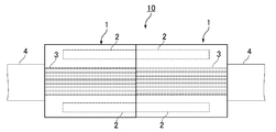
- thermo deformation inhibitory property In the evaluation of the thermal deformation inhibitory property, first, a connector (see FIG. 2) in which the MT ferrules of Examples 1 and 2 obtained as described above and another same MT ferrule were connected was prepared. In this connection, the insertion loss before and after heating at the solder reflow temperature (260 ° C.) was measured for each of the second and sixth optical fibers of the eight-core optical fibers, and the difference between the insertion losses before and after heating. The absolute value of was calculated. Then, the thermal deformation inhibitory property was evaluated based on the average value of the difference between the absolute values of the second and sixth optical fibers.
- reference numeral 10 indicates a connector of two MT ferrules with an 8-core optical fiber
- reference numeral 4 indicates a multi-core optical fiber ribbon.
- each MT ferrule 1 is prepared with an 8-core optical fiber ribbon 4 including eight single-mode optical fibers.
- the end faces of the two MT ferrules with fibers 1 were fixed to each other, and the two fitting pins were fitted into the guide holes 2 and abutted against each other. In this way, the connection body 10 of the two MT ferrules was prepared.
- the difference in insertion loss before and after heating at the solder reflow temperature (260 ° C.) measured for each of the eight-core optical fibers was specifically calculated as follows. (1) First, the insertion loss before heating at the solder reflow temperature (260 ° C.) was measured as follows.
- the reflection attenuation measuring device (product name "MBR5", manufactured by JGR, light source wavelength: 1310 nm) is attached to the eight optical fibers of one MT ferrule 1.
- the insertion loss (dB) was measured.
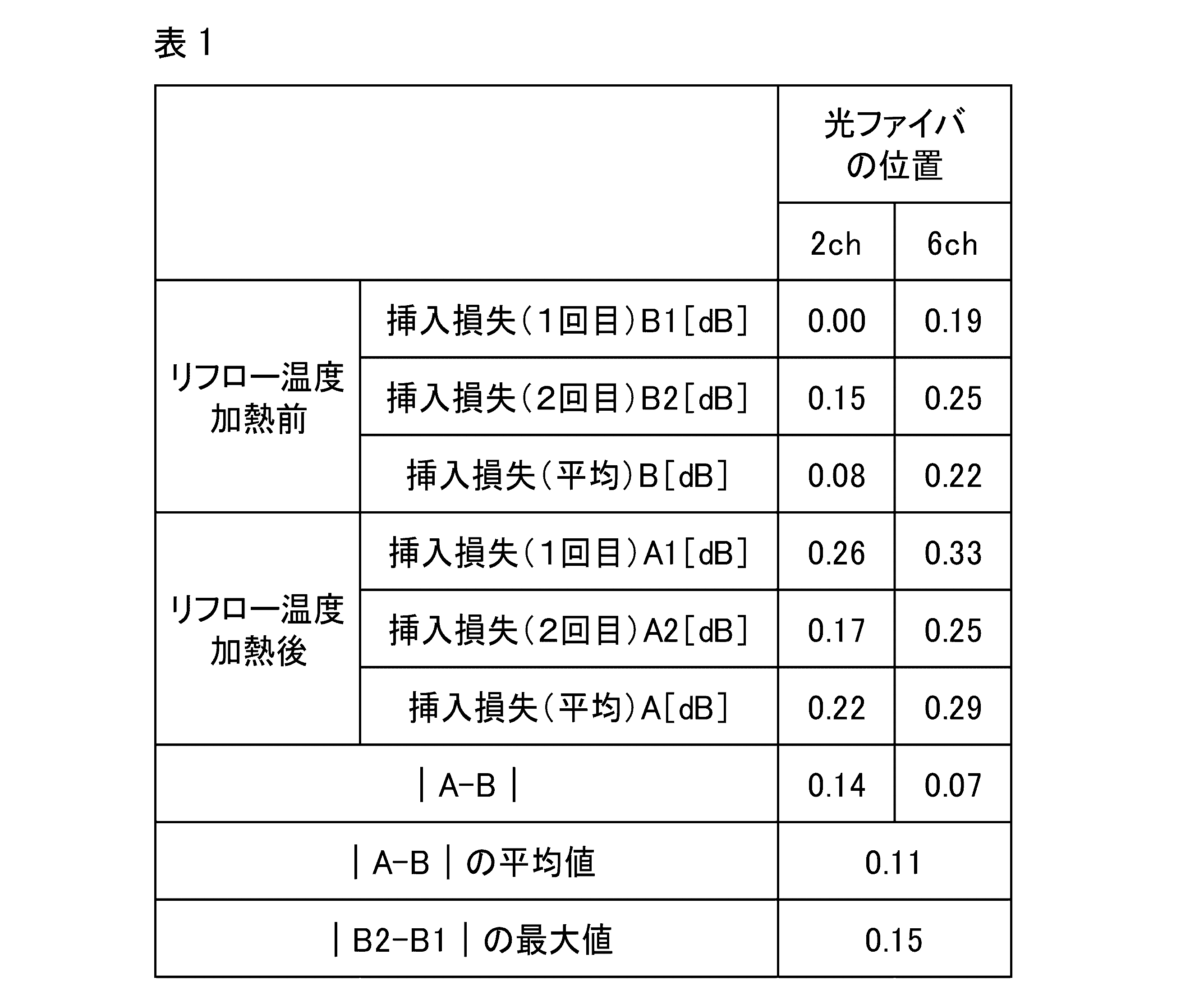
- Tables 1 and 2 show the results of the insertion loss (first time) B1 before heating at the solder reflow temperature, the insertion loss (second time) B2 before heating at the solder reflow temperature, and the average value B of these. ..
- the results of Example 1 are shown in Table 1, and the results of Example 2 are shown in Table 2.
- the values of B1 and B2 are relative values when the insertion loss of the optical fiber having the smallest insertion loss among the second and sixth optical fibers is set to 0 dB.
- the insertion loss after heating at the solder reflow temperature (260 ° C.) was measured as follows. That is, after the two MT ferrules 1 are heated at the solder reflow temperature (260 ° C.) for 5 minutes with the two MT ferrules 1 removed from the reflection attenuation measuring instrument, the insertion measuring instrument is connected to the optical fiber fixed to one MT ferrule 1 again. Then, the insertion loss (dB) was measured again. At this time, the measurement was performed twice, and the average value of the two measurements was used as the measured value.
- Tables 1 and 2 show the results of the insertion loss (first time) A1 after heating at the reflow temperature, the insertion loss (second time) A2 after heating at the reflow temperature, and the average value A thereof.
- the values of A1 and A2 are also relative values when the insertion loss of the optical fiber having the smallest insertion loss among the insertion losses before heating at the solder reflow temperature in the second and sixth optical fibers is set to 0 dB. And said.
- the absolute value of the difference between A and B calculated as described above was calculated. The results are shown in Tables 1 and 2.
- the external dimensions of the end face (height H x width W), the distance S between the two guide holes, and the distance s (horizontal pitch) between adjacent fiber holes are as follows, and are the same as the above design values. It was found that the differences between the two were extremely small. External dimensions of end face: 2.45 mm (H) x 6.38 mm (W) Spacing between two guide holes S: 4.6006 mm Horizontal pitch p of fiber holes: 0.25 mm ⁇ 0.001 mm
- Example 1 the average value of the absolute values of the differences between A and B was 0.11 dB, which was a small value from the results shown in Table 1.
- the absolute value of the difference between B1 and B2 which is the insertion loss before heating at the reflow temperature
- the insertion loss after heating at the reflow temperature was higher than that before heating. It could not be said that it increased, and it was found that the thermal deformation was sufficiently suppressed.
- Example 2 from the results shown in Table 2, the average value of the absolute values of the differences between A and B was 0.08 dB, which was a small value.
- the optical communication component can be easily molded, excellent dimensional accuracy can be imparted to the optical communication component, and the optical communication component is heated at the solder reflow temperature. Even so, it was confirmed that the thermal deformation of optical communication components can be sufficiently suppressed.
Landscapes
- Chemical & Material Sciences (AREA)
- Health & Medical Sciences (AREA)
- Chemical Kinetics & Catalysis (AREA)
- Medicinal Chemistry (AREA)
- Polymers & Plastics (AREA)
- Organic Chemistry (AREA)
- Mechanical Coupling Of Light Guides (AREA)
- Compositions Of Macromolecular Compounds (AREA)
Abstract
光通信部品用樹脂組成物は、ポリエーテルエーテルケトン樹脂を主成分として含むベース樹脂と、シリカとを含有する光通信部品用樹脂組成物であって、光通信部品用樹脂組成物中のシリカの含有率が55~75質量%である。
Description
本発明は、光通信部品用樹脂組成物及びこれを用いた光通信部品に関する。
光コネクタ用フェルール、スリーブ等の光通信部品は一般に樹脂と無機フィラーとを含む樹脂組成物で構成される。また光通信部品には高度な寸法精度が要求される。このため、光通信部品を構成する樹脂組成物には、容易に成形でき且つ優れた寸法精度を光通信部品に付与できることが求められる。このような光通信部品を構成する樹脂組成物として、従来、ポリフェニレンスルフィド樹脂(PPS樹脂)20~35重量%及びフィラー80~65重量%からなるPPS樹脂組成物を用いることが提案されている(例えば下記特許文献1参照)。
ところで、近年、光コネクタ用フェルールなどの光通信部品を回路基板に実装した状態ではんだリフローを行うことに対する要求が高まっている。
しかし、上記特許文献1に記載の光通信部品用樹脂組成物は、光通信部品を容易に成形でき、優れた寸法精度を光通信部品に付与できるものの、以下に示す課題を有している。
すなわち、上記特許文献1に記載の光通信部品用樹脂組成物で構成される光通信部品を回路基板に実装した状態ではんだリフローを行うと、熱変形が生じる場合がある。
本発明は、上記事情に鑑みてなされたものであり、光通信部品を容易に成形でき、光通信部品に優れた寸法精度を付与できるととともに、光通信部品をはんだリフロー温度で加熱しても光通信部品の熱変形を十分に抑制できる光通信部品用樹脂組成物及びこれを用いた光通信部品を提供することを目的とする。
本発明者は上記課題が生じる原因について検討した。まず、はんだリフロー温度は通常、約260℃であるのに対し、PPS樹脂の融点は約280℃である。従って、PPS樹脂を含む光コネクタ用フェルールをはんだリフロー温度で加熱しても、PPS樹脂は溶融しないはずであると本発明者は考えていた。しかし、本発明者がよく調べたところ、PPS樹脂では260℃近辺で部分的に結晶の溶融が起こることが判明した。このため、本発明者は、リフロー温度で加熱した時に、光コネクタ用フェルールのPPS樹脂の部分的な結晶の溶融の為にフェルールに変形が生じていることを見出した。そこで、本発明者は、PPS樹脂の代わりに、PPS樹脂よりも耐熱性の高いエポキシ樹脂やポリイミド樹脂を使用することを考えた。しかし、これらの樹脂は成形サイクルが長く生産性が劣る上、吸湿性が高く、長期間の使用で、吸湿により光コネクタ用フェルールを膨潤させるおそれがある。そこで、本発明者はさらに鋭意研究を進めた結果、PPS樹脂の代わりに、吸湿性が低く且つはんだリフロー温度付近で実質的に溶融することのないポリエーテルエーテルケトン樹脂(PEEK樹脂)を用いるのが有効ではないかと考えた。しかし、PPS樹脂をPEEK樹脂に変更するだけでは、フェルールに優れた寸法精度を付与できない場合があった。そこで、本発明者は、さらに鋭意研究を重ねた結果、以下の発明により、上記課題を解決し得ることを見出した。
本発明は、PEEK樹脂を主成分として含むベース樹脂と、シリカとを含有する光通信部品用樹脂組成物であって、前記光通信部品用樹脂組成物中の前記シリカの含有率が55~75質量%である、光通信部品用樹脂組成物である。
本発明の光通信部品用樹脂組成物は、光通信部品を容易に成形でき、光通信部品に優れた寸法精度を付与できるとともに、光通信部品をはんだリフロー温度で加熱しても、光通信部品の熱変形を十分に抑制できる。
上記光通信部品用樹脂組成物においては、前記ベース樹脂は、ポリアリーレンスルフィド(PAS)樹脂、ポリエーテルスルフォン樹脂(PES)、ポリエーテルイミド(PEI)樹脂、及び、融点が300℃以上の液晶性樹脂(LCP)からなる群より選ばれる少なくとも1種類の樹脂をさらに含むことが好ましい。
この場合、上記樹脂は、成形時においてPEEK樹脂よりも通常低い溶融粘度を有するため、ベース樹脂が上記樹脂を含まない場合に比べて、光通信部品用樹脂組成物の流動性を更に高めることができ、光通信部品をより容易に成形できる。また、上記樹脂は、PEEK樹脂よりも低い融点を有するが、高い結晶性を有するため一般的には高い融点を有し、低い線膨張係数を有するとともに吸湿性も低いため、光通信部品に優れた寸法精度を付与し、光通信部品をはんだリフロー温度で加熱した場合に上記樹脂以外の他の樹脂を用いる場合に比べて、光通信部品の熱変形をより十分に抑制できる。
上記光通信部品用樹脂組成物においては、前記ベース樹脂は上記PAS樹脂をさらに含むことが好ましい。
上記光通信部品用樹脂組成物においては、前記PAS樹脂がPPS樹脂であることが好ましい。
上記光通信部品用樹脂組成物においては、前記ベース樹脂中の前記PPS樹脂の含有率が20質量%以下であることが好ましい。
この場合、ベース樹脂中のPPS樹脂の含有率が20質量%を超える場合に比べて、光通信部品をはんだリフロー温度で加熱しても光通信部品の熱変形をより十分に抑制できる。
上記光通信部品用樹脂組成物においては、前記PEEK樹脂が、100cm3/10分以上のメルトボリュームレート(メルトボリュームレート条件:樹脂温度380℃、荷重5kg重、ISO1133準拠)を有することが好ましい。
この場合、PEEK樹脂のメルトボリュームレート(MVR)が100cm3/10分未満である場合に比べて、光通信部品の成形をより容易に行うことができる。
また本発明は、上述した光通信部品用樹脂組成物を含む光通信部品である。
本発明の光通信部品は、上述した光通信部品用樹脂組成物を含み、上述した光通信部品用樹脂組成物は、光通信部品を容易に成形でき、光通信部品に優れた寸法精度を付与できるとともに、光通信部品をはんだリフロー温度で加熱しても光通信部品の熱変形を十分に抑制できる。このため、本発明の光通信部品は、優れた外観及び寸法精度を有するとともに、はんだリフロー温度で加熱しても、熱変形を十分に抑制できる。
本発明によれば、光通信部品を容易に成形でき、光通信部品に優れた寸法精度を付与できるとともに、光通信部品をはんだリフロー温度で加熱しても光通信部品の熱変形を十分に抑制できる光通信部品用樹脂組成物及びこれを用いた光通信部品が提供される。
以下、本発明の実施形態について詳細に説明する。
<光通信部品用樹脂組成物>
本発明の光通信部品用樹脂組成物は、PEEK樹脂を主成分として含むベース樹脂と、シリカとを含有する。光通信部品用樹脂組成物中のシリカの含有率は55~75質量%である。
本発明の光通信部品用樹脂組成物は、PEEK樹脂を主成分として含むベース樹脂と、シリカとを含有する。光通信部品用樹脂組成物中のシリカの含有率は55~75質量%である。
本発明の光通信部品用樹脂組成物によれば、光通信部品を容易に成形でき、光通信部品に優れた寸法精度を付与できるとともに、光通信部品をはんだリフロー温度で加熱しても光通信部品の熱変形を十分に抑制できる。
以下、樹脂組成物について詳細に説明する。
(ベース樹脂)
ベース樹脂は、PEEK樹脂を主成分として含む。ここで、主成分とは、ベース樹脂中の含有率が50質量%以上である成分をいう。
ベース樹脂は、PEEK樹脂を主成分として含む。ここで、主成分とは、ベース樹脂中の含有率が50質量%以上である成分をいう。
PEEK樹脂は、下記構造式(1)で表される繰返し単位を有する。

上記構造式(1)中、R1、R2、R3はいずれも置換基であり、p,q,rはそれぞれ0~4の整数である。置換基として、例えば、ハロゲン基、アルキル基、アルケニル基、アリール基などの置換基が挙げられる。p,q,rはそれぞれ0であることが好ましい。
PEEK樹脂は上記繰返し単位をn個有する。nは平均重合度を表す正の整数である。
PEEK樹脂のMVRは特に制限されないが、100cm3/10分以上であることが好ましい。この場合、光通信部品用樹脂組成物のMVRが100cm3/10分未満である場合に比べて、光通信部品の成形をより容易に行うことができる。
PEEK樹脂のMVRは150cm3/10分以上であることがより好ましく、200cm3/10分以上であることが特に好ましい。
但し、PEEK樹脂のMVRは500cm3/10分以下であることが好ましい。この場合、PEEK樹脂のMVRが500cm3/10分を超える場合に比べて、PEEK樹脂の融点がより高くなり、光通信部品をはんだリフロー温度で加熱する場合に光通信部品の熱変形をより十分に抑制できる。加えて光通信部品の強度がより向上する。
ベース樹脂は、PEEK樹脂のみで構成されてもよく、PEEK樹脂と他の樹脂との混合樹脂で構成されてもよい。
他の樹脂としては、PAS樹脂、PES樹脂、PEI樹脂、融点が300℃以上のLCP又はこれらのうちの2種以上の組合せが好ましい。
この場合、上記他の樹脂は、成形時においてPEEK樹脂よりも通常低い溶融粘度を有するため、ベース樹脂が上記他の樹脂をさらに含まない場合に比べて、光通信部品用樹脂組成物の流動性を更に高めることができ、光通信部品をより容易に成形できる。また、上記他の樹脂は、PEEK樹脂よりも低い融点を有するが、高い結晶性を有するため一般的には高い融点を有し、低い線膨張係数を有するとともに吸湿性も低いため、光通信部品に優れた寸法精度を付与し、光通信部品をはんだリフロー温度で加熱した場合に上記他の樹脂以外の樹脂を用いる場合に比べて、光通信部品の熱変形をより十分に抑制できる。
中でも、上記他の樹脂としては、PAS樹脂が好ましい。PAS樹脂は、構造式[-Ar-S-](但し、Arはアリーレン基、Sは硫黄である)で示される繰返し単位を80モル%以上含有する重合体である。PAS樹脂の中でも、構造式[-Ph-S-](但し、Phはパラフェニレン基、Sは硫黄である)で示される繰返し単位を有するPPS樹脂が好ましい。
さらにPPS樹脂は、上記繰返し単位を80モル%以上含むことが好ましく、90モル%以上含むことがさらに好ましい。この場合、PPS樹脂の繰返し単位が80モル%未満である場合に比べて、PPS樹脂の結晶性と融点がより高くなり、PEEK樹脂にPPS樹脂を配合した場合でもはんだリフロー時の耐熱変形性が損われることがより十分に抑制される。
ベース樹脂中のPPS樹脂の含有率は20質量%以下であることが好ましい。この場合、ベース樹脂中のPPS樹脂の含有率が20質量%を超える場合に比べて、光通信部品をはんだリフロー温度で加熱した場合にPPS樹脂以外の樹脂を用いる場合に比べて、光通信部品の熱変形をより十分に抑制できる。
ベース樹脂中のPPS樹脂の含有率は10質量%以下であることがさらに好ましい。ベース樹脂中のPPS樹脂の含有率が10質量%を超える場合に比べて、はんだリフロー時の高温によりPPS樹脂の一部が溶融しにくく、成形品である光通信部品の熱変形をより十分に抑制できる。
但し、ベース樹脂中のPPS樹脂の含有率は2質量%以上であることがより好ましい。この場合、光通信部品用樹脂組成物の流動性をより高めることができるため、光通信部品用樹脂組成物の成形が容易となる。但し、PEEK樹脂のMVRが十分に高い場合は、必ずしもPPS樹脂を配合する必要はない。すなわち、PEEK樹脂のMVRが十分に高い場合は、ベース樹脂中のPPS樹脂の含有率は0質量%であってもよい。
光通信部品用樹脂組成物中のベース樹脂の含有率は、25~45質量%であることが好ましい。
この場合、光通信部品用樹脂組成物中のベース樹脂の含有率が25質量%未満である場合に比べて、光通信部品用樹脂組成物の流動性がより高くなり、光通信部品をより容易に成形できる。また、光通信部品用樹脂組成物中のベース樹脂の含有率が45質量%を超える場合に比べて、光通信部品に対してより優れた寸法精度を付与できる。
光通信部品用樹脂組成物中のベース樹脂の含有率は27質量%以上であることがより好ましく、29質量%以上であることが特に好ましい。
但し、光通信部品用樹脂組成物中のベース樹脂の含有率は42質量%以下であることがより好ましく、40質量%以下であることが特に好ましい。
(シリカ)
本発明に用いるシリカとしては、非晶質シリカ(溶融シリカ)及び結晶質シリカ(石英、クリストバライトほか)などが挙げられる。
本発明に用いるシリカとしては、非晶質シリカ(溶融シリカ)及び結晶質シリカ(石英、クリストバライトほか)などが挙げられる。
シリカは、非晶質シリカ及び結晶質シリカのいずれであってもよいが、本発明で使用されるシリカとしては、非晶質シリカが好適である。この場合、非晶質シリカは、結晶質シリカに比べて、硬度が低いため、光通信部品用樹脂組成物の成形加工に使用される機器を傷めることをより十分に抑制できる。
また、シリカの形状は、球状でも、粉砕した不定形であってもよいが、球状であることが好ましい。この場合、球状ではなく、粉砕した不定形のシリカが用いられる場合に比べて、ベース樹脂に配合した場合の材料の流動性がより高くなり成形品の寸法精度がより向上する。
シリカの形状が球状である場合、シリカは溶融法で作られることが特に好ましい。
シリカの球状度は、一般に円形度によって表され、円形度は、0.80以上であることが好ましい。この場合、線膨張係数の異方性がより低い光通信部品を成形できる。円形度は、0.85以上であることがより好ましく、0.90以上であることが特に好ましい。ここでシリカの円形度は、シリカ粒子個々の投影像を撮影し、その投影像の周囲長及び相当円の周囲長から下記式(2)により定義される。
(円形度)=(相当円の周囲長)/(粒子投影像の周囲長)・・・(2)
具体的には円形度は、シスメックス社製フロー式粒子像分析装置FPIA-1000を用いて測定され、測定値の平均値が円形度として求められる。通常、粒子のサンプリング数は200個程度である。
(円形度)=(相当円の周囲長)/(粒子投影像の周囲長)・・・(2)
具体的には円形度は、シスメックス社製フロー式粒子像分析装置FPIA-1000を用いて測定され、測定値の平均値が円形度として求められる。通常、粒子のサンプリング数は200個程度である。
なお、上記式(2)中、「相当円」とは、測定対象のシリカ粒子の投影像と同じ面積を持つ仮想円を表し、粒子が完全球状ならば投影像も完全円となり円形度は1になる。1つの粒子投影像の周囲長をL、面積をSとした場合、円形度は下記式で計算できる。
円形度=4πS/L2
円形度=4πS/L2
シリカの平均粒径は特に制限されないが、1μm以上であることが好ましい。この場合、シリカの平均粒径が1μm未満である場合に比べて、光通信部品用樹脂組成物がより高い流動性を有し成形性により優れる為、光通信部品用樹脂組成物を成形して得られる成形品の寸法精度がより向上する。
但し、シリカの平均粒径は、30μm以下であることが好ましい。この場合、シリカの平均粒径が30μmを超える場合に比べて、光通信部品用樹脂組成物の機械的強度及び寸法精度を向上させることができる。
尚、平均粒径はレーザー回折散乱式粒度分布測定装置により測定された値である。
光通信部品用樹脂組成物中のシリカの含有率は55~75質量%である。この場合、光通信部品用樹脂組成物中のシリカの含有率が55質量%未満である場合に比べて、光通信部品に対してより優れた寸法精度を付与できる。また、光通信部品用樹脂組成物中のシリカの含有率が75質量%を超える場合に比べて、光通信部品用樹脂組成物の流動性がより高くなり、光通信部品をより容易に成形できる。
光通信部品用樹脂組成物中のシリカの含有率は73質量%以下であることが好ましく、71質量%以下であることが特に好ましい。
但し、光通信部品用樹脂組成物中のシリカの含有率は58質量%以上であることがより好ましく、60質量%以上であることが特に好ましい。
(その他の成分)
本発明の光通信部品用樹脂組成物は、本発明の目的が損なわれない範囲で、上記ベース樹脂及びシリカに加えて、必要に応じてさらにその他の成分を含んでいてもよい。その他の成分としては、例えば酸化防止剤、耐候剤、滑剤、可塑剤、帯電防止剤、着色剤、シリカ以外の無機フィラーなどが挙げられる。
本発明の光通信部品用樹脂組成物は、本発明の目的が損なわれない範囲で、上記ベース樹脂及びシリカに加えて、必要に応じてさらにその他の成分を含んでいてもよい。その他の成分としては、例えば酸化防止剤、耐候剤、滑剤、可塑剤、帯電防止剤、着色剤、シリカ以外の無機フィラーなどが挙げられる。
シリカ以外の無機フィラーとしては、例えば、チタン酸カリウムに代表される無機ウィスカー、ナノシリカ、カーボンナノファイバー(以下CNF)に代表されるナノフィラーが挙げられる。これらは材料をミクロ補強して、導電性、表面滑り性、平滑性といった機能を光通信部品用樹脂組成物に付与できる。
上記光通信部品用樹脂組成物は、ベース樹脂及びシリカ等を粉体混合した後、溶融混練することにより得ることができる。混練は、例えば単軸押出機、二軸混練押出機等の混練機で行うことができる。
<光通信部品>
次に、本発明の光通信部品について説明する。
次に、本発明の光通信部品について説明する。
本発明の光通信部品は、上述した光通信部品に樹脂組成物を含む。
上述した光通信部品用樹脂組成物は、光通信部品を容易に成形でき、光通信部品に優れた寸法精度を付与できるとともに、光通信部品をはんだリフロー温度で加熱しても光通信部品の熱変形を十分に抑制できる。このため、本発明の光通信部品は、優れた外観及び寸法精度を有するとともに、はんだリフロー温度で加熱しても、熱変形を十分に抑制できる。
光通信部品としては、例えば光コネクタ用フェルール、フェルールを収納するスリーブ等が挙げられる。中でも、本発明は、極めて高い寸法精度が要求され、回路基板に実装されてはんだリフローが行われることもある光コネクタ用フェルールに特に有効である。
光コネクタ用フェルールの光コネクタは、単心用光コネクタでも多心用光コネクタでもよい。またフェルールとしては、MTフェルール、SCフェルール及びLCフェルール等が挙げられる。
光通信部品は、例えば射出成形又はトランスファー成形によって成形することができる。
以下、実施例を挙げて本発明の内容をより具体的に説明するが、本発明は、以下の実施例に限定されるものではない。
(実施例1)
ベース樹脂及びシリカを30:70(質量比)の割合で、ヘンシェルミキサーを用いて均一にドライブレンドした後、二軸混練押出機(製品名「TEM37SS」、東芝機械株式会社製)を用いて、樹脂温度380~410℃にて溶融混練し、樹脂組成物のペレットを得た。このとき、ベース樹脂及びシリカとしては具体的には下記のものを用いた。
(1)ベース樹脂
ベース樹脂としては、下記PEEK樹脂と下記PPS樹脂とを95:5(質量比)で混合してなる混合樹脂を用いた。
(PEEK樹脂)
PEEK樹脂として、ダイセルエボニック株式会社製の商品名「1000P」を用いた。この樹脂は、上記構造式(1)のp、q、rが0であり、ISO1133に基づき、380℃、荷重5kg重の条件で測定したMVRが150cm3/10分であった。
(PPS樹脂)
PPS樹脂として、東ソー株式会社製の商品名「#140」を用いた。
(2)シリカ
シリカとして、表面処理された球状非晶質シリカ(商品名「TSS-6 ビニルシラン処理」、株式会社龍森製、円形度:0.93、平均粒径:5μm)を用いた。
次に、上記のようにして得られたペレットを、型締力10トンの電動射出成形機に投入し、フェルール成形用金型により、樹脂温度400~420℃、金型設定温度200℃、保持圧力100MPaの成形条件で射出成形を行い、図1に示す8心用のMTフェルールを、端面の外形寸法(縦×横)、2つのガイド穴の間隔S、隣接するファイバ孔同士間の間隔p(横ピッチ)が下記設計値となるように作製した。なお、図1において、符号1はMTフェルール、符号1aはMTフェルールの端面、符号2はガイド穴、符号3はファイバ孔を示す。
(設計値)
端面の外形寸法 :2.5mm(H)×6.4mm(W)
2つのガイド穴の間隔S :4.6mm
ファイバ孔の横ピッチp :0.25mm
(設計値)
端面の外形寸法 :2.5mm(H)×6.4mm(W)
2つのガイド穴の間隔S :4.6mm
ファイバ孔の横ピッチp :0.25mm
(実施例2)
樹脂組成物のペレットを得る際に、ベース樹脂及びシリカを40:60(質量比)の割合で混合し、ペレットの成形条件を、樹脂温度420℃、金型設定温度200℃、保持圧力100MPaとしたこと以外は実施例1と同様にしてMTフェルールを作製した。
樹脂組成物のペレットを得る際に、ベース樹脂及びシリカを40:60(質量比)の割合で混合し、ペレットの成形条件を、樹脂温度420℃、金型設定温度200℃、保持圧力100MPaとしたこと以外は実施例1と同様にしてMTフェルールを作製した。
[特性評価]
上記のようにして得られた実施例1及び2のMTフェルールについて、以下のようにして寸法精度、成形性及び熱変形抑制性を評価した。
上記のようにして得られた実施例1及び2のMTフェルールについて、以下のようにして寸法精度、成形性及び熱変形抑制性を評価した。
(成形性)
上記のようにして得られた実施例1及び2のMTフェルールについて、「ひけ」又は「ボイド」の無いものを作製するのに必要な回数で成形性を評価した。なお、「ひけ」の有無はMTフェルールの外観から判断し、「ボイドの有無」はX線検査により調べた。
上記のようにして得られた実施例1及び2のMTフェルールについて、「ひけ」又は「ボイド」の無いものを作製するのに必要な回数で成形性を評価した。なお、「ひけ」の有無はMTフェルールの外観から判断し、「ボイドの有無」はX線検査により調べた。
(寸法精度)
上記のようにして得られた実施例1及び2のMTフェルールについて、図1に示す端面の外形寸法(高さH×幅W)、2つのガイド穴の間隔S、隣接するファイバ孔同士間の間隔p(横ピッチ)と上記設計値との差を調べることによって評価した。
上記のようにして得られた実施例1及び2のMTフェルールについて、図1に示す端面の外形寸法(高さH×幅W)、2つのガイド穴の間隔S、隣接するファイバ孔同士間の間隔p(横ピッチ)と上記設計値との差を調べることによって評価した。
(熱変形抑制性)
熱変形抑制性の評価にあたり、まず、上記のようにして得られた実施例1及び2のMTフェルールと、同一の別のMTフェルールとを接続した接続体(図2参照)を準備した。この接続体において、8心の光ファイバのうち2番目及び6番目の光ファイバの各々について、はんだリフロー温度(260℃)での加熱前後の挿入損失を測定し、加熱前後における当該挿入損失の差の絶対値を求めた。そして、2番目及び6番目の光ファイバの当該絶対値の差の平均値に基づいて熱変形抑制性を評価した。すなわち、このはんだリフロー温度(260℃)での加熱前後の挿入損失の差の絶対値の平均値が小さければ、熱変形抑制性が大きく、大きければ熱変形抑制性が小さいと評価した。なお、図2において、符号10は2つの8心光ファイバ付きMTフェルールの接続体、符号4は、多心光ファイバリボンを示す。
このとき、2つの8心光ファイバ付きMTフェルールの接続体を以下のようにして用意した。すなわち、図2に示すように、まず実施例1及び2のそれぞれについてMTフェルール1を2つずつ用意し、各MTフェルール1に、8本のシングルモード光ファイバを含む8心光ファイバリボン4を固定して、2つのファイバ付きMTフェルール1の端面同士を、2本の嵌合ピンをガイド穴2に嵌合させて互いに突き合わせた。こうして2つのMTフェルールの接続体10を用意した。
また、8心の光ファイバの各々について測定したはんだリフロー温度(260℃)での加熱前後の挿入損失の差は、具体的には以下のようにして算出した。
(1)まず、はんだリフロー温度(260℃)での加熱前の挿入損失を以下のようにして測定した。
すなわち、2つの8心光ファイバ付きMTフェルールの接続体10において、一方のMTフェルール1の8本の光ファイバに反射減衰量測定器(製品名「MBR5」、JGR社製、光源波長:1310nm)を接続して挿入損失(dB)を測定した。このとき、測定は2回行い、2回の平均値を測定値として用いた。こうして測定されたはんだリフロー温度での加熱前の挿入損失(1回目)B1、はんだリフロー温度での加熱前の挿入損失(2回目)B2、これらの平均値Bの結果を表1及び2に示す。なお、表1には実施例1の結果が示され、表2には実施例2の結果が示されている。また、B1,B2の値は、2番目及び6番目の光ファイバのうち最も挿入損失の小さい光ファイバの挿入損失を0dBとしたときの相対値とした。
(2)次に、はんだリフロー温度(260℃)での加熱後の挿入損失を以下のようにして測定した。
すなわち、2つのMTフェルール1を、反射減衰量測定器から取り外した状態ではんだリフロー温度(260℃)で5分間加熱した後、再び一方のMTフェルール1に固定した光ファイバに挿入測定器を接続して再度挿入損失(dB)を測定した。このとき、測定は2回行い、2回の平均値を測定値として用いた。こうして測定されたリフロー温度での加熱後の挿入損失(1回目)A1、リフロー温度での加熱後の挿入損失(2回目)A2、これらの平均値Aの結果を表1及び2に示す。なお、A1,A2の値についても、2番目及び6番目の光ファイバにおけるはんだリフロー温度での加熱前の挿入損失のうち、最も挿入損失の小さい光ファイバの挿入損失を0dBとしたときの相対値とした。
(3)最後に、上記のようにして算出したAとBとの差の絶対値を算出した。結果を表1及び表2に示す。
成形性については、実施例1及び2のいずれにおいても、「ひけ」も「ボイド」も無いMTフェルールを1回で成形することができた。従って、実施例1及び2のいずれの樹脂組成物についても容易に成形を行うことができることが分かった。
寸法精度については、端面の外形寸法(高さH×幅W)、2つのガイド穴の間隔S、隣接するファイバ孔同士間の間隔s(横ピッチ)は下記の通りであり、上記設計値との差がいずれも極めて小さいことが分かった。
端面の外形寸法 :2.45mm(H)×6.38mm(W)
2つのガイド穴の間隔S :4.6006mm
ファイバ孔の横ピッチp :0.25mm±0.001mm
端面の外形寸法 :2.45mm(H)×6.38mm(W)
2つのガイド穴の間隔S :4.6006mm
ファイバ孔の横ピッチp :0.25mm±0.001mm
熱変形抑制性については、実施例1では、表1に示す結果より、AとBの差の絶対値の平均値は0.11dBであり、小さい値であった。特に、リフロー温度での加熱前の挿入損失であるB1とB2との差の絶対値が最大で0.15dBであったことから、リフロー温度での加熱後の挿入損失は、加熱前と比べて増加しているとは言えず、熱変形が十分に抑制されていることが分かった。また、実施例2については、表2に示す結果より、AとBの差の絶対値の平均値は0.08dBであり、小さい値であった。リフロー温度での加熱前の挿入損失であるB1とB2との差の絶対値が最大で0.09dBであったことから、はんだリフロー温度での加熱後の挿入損失は、加熱前と比べて増加しているとは言えず、熱変形が十分に抑制されていることが分かった。
以上のことから、本発明の光通信部品用樹脂組成物によれば、光通信部品を容易に成形でき、光通信部品に優れた寸法精度を付与できるとともに、光通信部品をはんだリフロー温度で加熱しても光通信部品の熱変形を十分に抑制できることが確認された。
Claims (7)
- ポリエーテルエーテルケトン樹脂を主成分として含むベース樹脂と、
シリカとを含有する光通信部品用樹脂組成物であって、
前記光通信部品用樹脂組成物中の前記シリカの含有率が55~75質量%である、
光通信部品用樹脂組成物。 - 前記ベース樹脂が、ポリアリーレンスルフィド樹脂、ポリエーテルスルフォン樹脂、ポリエーテルイミド樹脂、及び、融点が300℃以上の液晶性樹脂からなる群より選ばれる少なくとも1種類の樹脂をさらに含む、
請求項1に記載の光通信部品用樹脂組成物。 - 前記ベース樹脂が、前記ポリアリーレンスルフィド樹脂をさらに含む、
請求項2に記載の光通信部品用樹脂組成物。 - 前記ポリアリーレンスルフィド樹脂がポリフェニレンスルフィド樹脂である、
請求項3に記載の光通信部品用樹脂組成物。 - 前記ベース樹脂中の前記ポリフェニレンスルフィド樹脂の含有率が20質量%以下である、
請求項4に記載の光通信部品用樹脂組成物。 - 前記ポリエーテルエーテルケトン樹脂が、100cm3/10分以上のメルトボリュームレート(メルトボリュームレート条件:樹脂温度380℃、荷重5kg重、ISO1133準拠)を有する、
請求項1~5のいずれか一項に記載の光通信部品用樹脂組成物。 - 請求項1~6のいずれか一項に記載の光通信部品用樹脂組成物を含む光通信部品。
Priority Applications (3)
| Application Number | Priority Date | Filing Date | Title |
|---|---|---|---|
| CN202080039081.XA CN113874440A (zh) | 2019-08-07 | 2020-07-31 | 光通信部件用树脂组合物和使用其的光通信部件 |
| EP20850271.6A EP4011979A4 (en) | 2019-08-07 | 2020-07-31 | RESIN COMPOSITION FOR OPTICAL COMMUNICATION COMPONENT AND OPTICAL COMMUNICATION COMPONENT USING SAME |
| US17/613,997 US12264242B2 (en) | 2019-08-07 | 2020-07-31 | Resin composition for optical communication component and optical communication component using the resin composition |
Applications Claiming Priority (2)
| Application Number | Priority Date | Filing Date | Title |
|---|---|---|---|
| JP2019145155A JP6901530B2 (ja) | 2019-08-07 | 2019-08-07 | 光通信部品用樹脂組成物及びこれを用いた光通信部品 |
| JP2019-145155 | 2019-08-07 |
Publications (1)
| Publication Number | Publication Date |
|---|---|
| WO2021024932A1 true WO2021024932A1 (ja) | 2021-02-11 |
Family
ID=74503835
Family Applications (1)
| Application Number | Title | Priority Date | Filing Date |
|---|---|---|---|
| PCT/JP2020/029391 Ceased WO2021024932A1 (ja) | 2019-08-07 | 2020-07-31 | 光通信部品用樹脂組成物及びこれを用いた光通信部品 |
Country Status (5)
| Country | Link |
|---|---|
| US (1) | US12264242B2 (ja) |
| EP (1) | EP4011979A4 (ja) |
| JP (1) | JP6901530B2 (ja) |
| CN (1) | CN113874440A (ja) |
| WO (1) | WO2021024932A1 (ja) |
Cited By (3)
| Publication number | Priority date | Publication date | Assignee | Title |
|---|---|---|---|---|
| JPWO2022176235A1 (ja) * | 2021-02-17 | 2022-08-25 | ||
| JPWO2022260068A1 (ja) * | 2021-06-11 | 2022-12-15 | ||
| WO2024024348A1 (ja) * | 2022-07-28 | 2024-02-01 | 古河電気工業株式会社 | フェルール、フェルールの製造方法、フェルール付きファイバリボン及びフェルール付きファイバリボンの製造方法 |
Families Citing this family (1)
| Publication number | Priority date | Publication date | Assignee | Title |
|---|---|---|---|---|
| WO2026034486A1 (ja) * | 2024-08-05 | 2026-02-12 | 株式会社フジクラ | 光通信部品用樹脂組成物及びこれを用いた光通信部品 |
Citations (4)
| Publication number | Priority date | Publication date | Assignee | Title |
|---|---|---|---|---|
| JP2000273304A (ja) | 1999-03-23 | 2000-10-03 | Idemitsu Petrochem Co Ltd | 光通信部品用ポリアリーレンスルフィド樹脂組成物 |
| JP2012516022A (ja) * | 2009-01-20 | 2012-07-12 | アーケマ・インコーポレイテッド | 高性能コネクター |
| CN102977549A (zh) * | 2012-12-30 | 2013-03-20 | 南京肯特复合材料有限公司 | 改性peek、制备方法及其在通讯领域连接器上的应用 |
| WO2017073572A1 (ja) * | 2015-10-26 | 2017-05-04 | 株式会社トクヤマデンタル | 樹脂ブロック及びその製造方法 |
Family Cites Families (12)
| Publication number | Priority date | Publication date | Assignee | Title |
|---|---|---|---|---|
| JP2695921B2 (ja) * | 1989-06-16 | 1998-01-14 | 株式会社日立製作所 | 伝送媒体をインサート成形した回路構造体 |
| JPH03217278A (ja) * | 1990-01-23 | 1991-09-25 | Toray Ind Inc | ポリアリーレンスルフィド被覆体の製造法 |
| JP2000001615A (ja) * | 1998-06-15 | 2000-01-07 | Idemitsu Petrochem Co Ltd | ポリアリーレンスルフィド樹脂組成物 |
| JP4295848B2 (ja) | 1998-12-24 | 2009-07-15 | 出光興産株式会社 | 電子部品封止用ポリアリーレンスルフィド樹脂組成物 |
| JP4919542B2 (ja) | 2001-05-29 | 2012-04-18 | 出光興産株式会社 | 光学部品用樹脂組成物および光学部品 |
| JP3969213B2 (ja) | 2002-06-26 | 2007-09-05 | 住友電気工業株式会社 | 光コネクタ |
| WO2013089078A1 (ja) * | 2011-12-15 | 2013-06-20 | 株式会社トクヤマデンタル | 樹脂複合材料、歯科用材料および樹脂複合材料の製造方法 |
| CN103435947B (zh) * | 2013-08-30 | 2015-09-02 | 广州机械科学研究院有限公司 | 耐磨损、低蠕变聚四氟乙烯密封材料及其制备方法与应用 |
| CN103665368B (zh) | 2013-11-28 | 2017-01-11 | 张家港祥成医用材料科技有限公司 | 一种在纳米/微米尺度无机种床上的聚芳醚酮树脂低温合成方法 |
| WO2019042948A1 (en) | 2017-08-28 | 2019-03-07 | Solvay Specialty Polymers Usa, Llc | GLASS-CHARGED POLYMER COMPOSITION COMPRISING A POLY (ARYL ETHER SULFONE), A POLY (ARYL ETHER KETONE), AT LEAST ONE POLY (PHENYLENE SULFIDE) AND GLASS FIBERS |
| CN107767989A (zh) | 2017-10-18 | 2018-03-06 | 扬州大学 | 一种聚醚醚酮高压柔性直流输电光纤复合挤出电缆 |
| WO2019168009A1 (ja) * | 2018-02-27 | 2019-09-06 | 三菱ケミカル株式会社 | 繊維強化熱可塑性樹脂プリプレグおよび成形体 |
-
2019
- 2019-08-07 JP JP2019145155A patent/JP6901530B2/ja active Active
-
2020
- 2020-07-31 CN CN202080039081.XA patent/CN113874440A/zh active Pending
- 2020-07-31 EP EP20850271.6A patent/EP4011979A4/en not_active Withdrawn
- 2020-07-31 WO PCT/JP2020/029391 patent/WO2021024932A1/ja not_active Ceased
- 2020-07-31 US US17/613,997 patent/US12264242B2/en active Active
Patent Citations (4)
| Publication number | Priority date | Publication date | Assignee | Title |
|---|---|---|---|---|
| JP2000273304A (ja) | 1999-03-23 | 2000-10-03 | Idemitsu Petrochem Co Ltd | 光通信部品用ポリアリーレンスルフィド樹脂組成物 |
| JP2012516022A (ja) * | 2009-01-20 | 2012-07-12 | アーケマ・インコーポレイテッド | 高性能コネクター |
| CN102977549A (zh) * | 2012-12-30 | 2013-03-20 | 南京肯特复合材料有限公司 | 改性peek、制备方法及其在通讯领域连接器上的应用 |
| WO2017073572A1 (ja) * | 2015-10-26 | 2017-05-04 | 株式会社トクヤマデンタル | 樹脂ブロック及びその製造方法 |
Non-Patent Citations (1)
| Title |
|---|
| See also references of EP4011979A4 |
Cited By (9)
| Publication number | Priority date | Publication date | Assignee | Title |
|---|---|---|---|---|
| JPWO2022176235A1 (ja) * | 2021-02-17 | 2022-08-25 | ||
| WO2022176235A1 (ja) * | 2021-02-17 | 2022-08-25 | 株式会社フジクラ | 光コネクタ用フェルールおよび光コネクタの製造方法 |
| JPWO2022260068A1 (ja) * | 2021-06-11 | 2022-12-15 | ||
| WO2022260068A1 (ja) * | 2021-06-11 | 2022-12-15 | 株式会社白山 | 多心光コネクタ用フェルールおよび光モジュール |
| US20240272377A1 (en) * | 2021-06-11 | 2024-08-15 | Hakusan Inc. | Multi-fiber optical connector ferrule and optical module |
| JP7837332B2 (ja) | 2021-06-11 | 2026-03-30 | 株式会社白山 | 多心光コネクタ用フェルールおよび光モジュール |
| WO2024024348A1 (ja) * | 2022-07-28 | 2024-02-01 | 古河電気工業株式会社 | フェルール、フェルールの製造方法、フェルール付きファイバリボン及びフェルール付きファイバリボンの製造方法 |
| JP2024017752A (ja) * | 2022-07-28 | 2024-02-08 | 古河電気工業株式会社 | フェルール、フェルールの製造方法、フェルール付きファイバリボン及びフェルール付きファイバリボンの製造方法 |
| JP7687998B2 (ja) | 2022-07-28 | 2025-06-03 | 古河電気工業株式会社 | フェルール、フェルールの製造方法、フェルール付きファイバリボン及びフェルール付きファイバリボンの製造方法 |
Also Published As
| Publication number | Publication date |
|---|---|
| JP2021024971A (ja) | 2021-02-22 |
| US12264242B2 (en) | 2025-04-01 |
| EP4011979A1 (en) | 2022-06-15 |
| CN113874440A (zh) | 2021-12-31 |
| EP4011979A4 (en) | 2023-09-06 |
| US20220220297A1 (en) | 2022-07-14 |
| JP6901530B2 (ja) | 2021-07-14 |
Similar Documents
| Publication | Publication Date | Title |
|---|---|---|
| JP6901530B2 (ja) | 光通信部品用樹脂組成物及びこれを用いた光通信部品 | |
| JP7837332B2 (ja) | 多心光コネクタ用フェルールおよび光モジュール | |
| JP3433422B2 (ja) | ガイド穴を有する光コネクタ用多心フェルール | |
| WO1999053352A1 (en) | Part for positioning optical fiber | |
| CN119585655A (zh) | 套箍、套箍的制造方法、带套箍的光纤带及带套箍的光纤带的制造方法 | |
| JP2016133518A (ja) | 光学素子及び光学素子の製造方法 | |
| JPH06299072A (ja) | 光ファイバ用コネクタフェルール | |
| JP2003003074A (ja) | シリカ含有樹脂組成物およびその精密成形体 | |
| WO2021192419A1 (ja) | 光コネクタ部品、光通信部品用樹脂組成物及び光通信部品 | |
| EP1384756A1 (en) | Polyarylene sulfide resin composition for optical communication part | |
| JP2003292734A (ja) | エポキシ樹脂組成物及びそれを用いた光学部品 | |
| JP3354253B2 (ja) | 光ファイバ用フェルール並びにこれを用いたコネクタ及び光スイッチ | |
| US20240134130A1 (en) | Ferrule and method for manufacturing ferrule | |
| JP7096454B1 (ja) | ポリアリーレンサルファイド樹脂組成物、成形品、及び光フェルール | |
| JP3405969B2 (ja) | 変換コネクタ用プラスチック割りスリーブ | |
| JP3969213B2 (ja) | 光コネクタ | |
| JP2012036281A (ja) | 位置決め治具 | |
| JP7608392B2 (ja) | 射出成形用樹脂組成物、射出成形品、射出成形品の製造方法および射出成形品の解析方法 | |
| JP2026003374A (ja) | 光接続部品用樹脂組成物、mtフェルールおよび光接続部品用樹脂組成物の製造方法 | |
| JPWO1999053352A1 (ja) | 光ファイバ位置決め部品 | |
| US20160032085A1 (en) | Polyarylene sulfide resin composition and use of same | |
| JPH10221566A (ja) | 光コネクタフェルール | |
| JP2003185886A (ja) | 光コネクタおよびその製造方法 | |
| CN105026967A (zh) | 光连接器 |
Legal Events
| Date | Code | Title | Description |
|---|---|---|---|
| 121 | Ep: the epo has been informed by wipo that ep was designated in this application |
Ref document number: 20850271 Country of ref document: EP Kind code of ref document: A1 |
|
| NENP | Non-entry into the national phase |
Ref country code: DE |
|
| ENP | Entry into the national phase |
Ref document number: 2020850271 Country of ref document: EP Effective date: 20220307 |
|
| WWG | Wipo information: grant in national office |
Ref document number: 17613997 Country of ref document: US |