WO2021027999A1 - Method of producing separator plates - Google Patents

Method of producing separator plates Download PDF

Info

Publication number
WO2021027999A1
WO2021027999A1 PCT/DK2020/000242 DK2020000242W WO2021027999A1 WO 2021027999 A1 WO2021027999 A1 WO 2021027999A1 DK 2020000242 W DK2020000242 W DK 2020000242W WO 2021027999 A1 WO2021027999 A1 WO 2021027999A1
Authority
WO
WIPO (PCT)
Prior art keywords
ptfe
suspension
separator plate
providing
powder
Prior art date
Legal status (The legal status is an assumption and is not a legal conclusion. Google has not performed a legal analysis and makes no representation as to the accuracy of the status listed.)
Ceased
Application number
PCT/DK2020/000242
Other languages
French (fr)
Inventor
Denys GROMADSKYI
Current Assignee (The listed assignees may be inaccurate. Google has not performed a legal analysis and makes no representation or warranty as to the accuracy of the list.)
Blue World Technologies Holding ApS
Original Assignee
Blue World Technologies Holding ApS
Priority date (The priority date is an assumption and is not a legal conclusion. Google has not performed a legal analysis and makes no representation as to the accuracy of the date listed.)
Filing date
Publication date
Application filed by Blue World Technologies Holding ApS filed Critical Blue World Technologies Holding ApS
Priority to EP20852159.1A priority Critical patent/EP4014268A4/en
Priority to CN202080056619.8A priority patent/CN114207889B/en
Priority to US17/635,175 priority patent/US12040512B2/en
Priority to JP2022508467A priority patent/JP7677948B2/en
Priority to KR1020227008315A priority patent/KR102873387B1/en
Publication of WO2021027999A1 publication Critical patent/WO2021027999A1/en
Anticipated expiration legal-status Critical
Ceased legal-status Critical Current

Links

Classifications

    • HELECTRICITY
    • H01ELECTRIC ELEMENTS
    • H01MPROCESSES OR MEANS, e.g. BATTERIES, FOR THE DIRECT CONVERSION OF CHEMICAL ENERGY INTO ELECTRICAL ENERGY
    • H01M8/00Fuel cells; Manufacture thereof
    • H01M8/02Details
    • H01M8/0202Collectors; Separators, e.g. bipolar separators; Interconnectors
    • H01M8/0204Non-porous and characterised by the material
    • H01M8/0223Composites
    • H01M8/0226Composites in the form of mixtures
    • HELECTRICITY
    • H01ELECTRIC ELEMENTS
    • H01MPROCESSES OR MEANS, e.g. BATTERIES, FOR THE DIRECT CONVERSION OF CHEMICAL ENERGY INTO ELECTRICAL ENERGY
    • H01M50/00Constructional details or processes of manufacture of the non-active parts of electrochemical cells other than fuel cells, e.g. hybrid cells
    • H01M50/40Separators; Membranes; Diaphragms; Spacing elements inside cells
    • H01M50/403Manufacturing processes of separators, membranes or diaphragms
    • HELECTRICITY
    • H01ELECTRIC ELEMENTS
    • H01MPROCESSES OR MEANS, e.g. BATTERIES, FOR THE DIRECT CONVERSION OF CHEMICAL ENERGY INTO ELECTRICAL ENERGY
    • H01M50/00Constructional details or processes of manufacture of the non-active parts of electrochemical cells other than fuel cells, e.g. hybrid cells
    • H01M50/40Separators; Membranes; Diaphragms; Spacing elements inside cells
    • H01M50/409Separators, membranes or diaphragms characterised by the material
    • H01M50/411Organic material
    • H01M50/414Synthetic resins, e.g. thermoplastics or thermosetting resins
    • H01M50/426Fluorocarbon polymers
    • HELECTRICITY
    • H01ELECTRIC ELEMENTS
    • H01MPROCESSES OR MEANS, e.g. BATTERIES, FOR THE DIRECT CONVERSION OF CHEMICAL ENERGY INTO ELECTRICAL ENERGY
    • H01M50/00Constructional details or processes of manufacture of the non-active parts of electrochemical cells other than fuel cells, e.g. hybrid cells
    • H01M50/40Separators; Membranes; Diaphragms; Spacing elements inside cells
    • H01M50/409Separators, membranes or diaphragms characterised by the material
    • H01M50/431Inorganic material
    • HELECTRICITY
    • H01ELECTRIC ELEMENTS
    • H01MPROCESSES OR MEANS, e.g. BATTERIES, FOR THE DIRECT CONVERSION OF CHEMICAL ENERGY INTO ELECTRICAL ENERGY
    • H01M50/00Constructional details or processes of manufacture of the non-active parts of electrochemical cells other than fuel cells, e.g. hybrid cells
    • H01M50/40Separators; Membranes; Diaphragms; Spacing elements inside cells
    • H01M50/409Separators, membranes or diaphragms characterised by the material
    • H01M50/446Composite material consisting of a mixture of organic and inorganic materials
    • HELECTRICITY
    • H01ELECTRIC ELEMENTS
    • H01MPROCESSES OR MEANS, e.g. BATTERIES, FOR THE DIRECT CONVERSION OF CHEMICAL ENERGY INTO ELECTRICAL ENERGY
    • H01M8/00Fuel cells; Manufacture thereof
    • H01M8/02Details
    • H01M8/0202Collectors; Separators, e.g. bipolar separators; Interconnectors
    • H01M8/0204Non-porous and characterised by the material
    • H01M8/0213Gas-impermeable carbon-containing materials
    • HELECTRICITY
    • H01ELECTRIC ELEMENTS
    • H01MPROCESSES OR MEANS, e.g. BATTERIES, FOR THE DIRECT CONVERSION OF CHEMICAL ENERGY INTO ELECTRICAL ENERGY
    • H01M8/00Fuel cells; Manufacture thereof
    • H01M8/02Details
    • H01M8/0202Collectors; Separators, e.g. bipolar separators; Interconnectors
    • H01M8/0204Non-porous and characterised by the material
    • H01M8/0221Organic resins; Organic polymers
    • HELECTRICITY
    • H01ELECTRIC ELEMENTS
    • H01MPROCESSES OR MEANS, e.g. BATTERIES, FOR THE DIRECT CONVERSION OF CHEMICAL ENERGY INTO ELECTRICAL ENERGY
    • H01M8/00Fuel cells; Manufacture thereof
    • H01M8/02Details
    • H01M8/0202Collectors; Separators, e.g. bipolar separators; Interconnectors
    • H01M8/023Porous and characterised by the material
    • H01M8/0234Carbonaceous material
    • HELECTRICITY
    • H01ELECTRIC ELEMENTS
    • H01MPROCESSES OR MEANS, e.g. BATTERIES, FOR THE DIRECT CONVERSION OF CHEMICAL ENERGY INTO ELECTRICAL ENERGY
    • H01M8/00Fuel cells; Manufacture thereof
    • H01M8/02Details
    • H01M8/0202Collectors; Separators, e.g. bipolar separators; Interconnectors
    • H01M8/023Porous and characterised by the material
    • H01M8/0239Organic resins; Organic polymers
    • HELECTRICITY
    • H01ELECTRIC ELEMENTS
    • H01MPROCESSES OR MEANS, e.g. BATTERIES, FOR THE DIRECT CONVERSION OF CHEMICAL ENERGY INTO ELECTRICAL ENERGY
    • H01M8/00Fuel cells; Manufacture thereof
    • H01M8/10Fuel cells with solid electrolytes
    • H01M8/1016Fuel cells with solid electrolytes characterised by the electrolyte material
    • H01M8/1018Polymeric electrolyte materials
    • H01M8/1041Polymer electrolyte composites, mixtures or blends
    • H01M8/1046Mixtures of at least one polymer and at least one additive
    • H01M8/1048Ion-conducting additives, e.g. ion-conducting particles, heteropolyacids, metal phosphate or polybenzimidazole with phosphoric acid
    • HELECTRICITY
    • H01ELECTRIC ELEMENTS
    • H01MPROCESSES OR MEANS, e.g. BATTERIES, FOR THE DIRECT CONVERSION OF CHEMICAL ENERGY INTO ELECTRICAL ENERGY
    • H01M8/00Fuel cells; Manufacture thereof
    • H01M8/24Grouping of fuel cells, e.g. stacking of fuel cells
    • H01M8/249Grouping of fuel cells, e.g. stacking of fuel cells comprising two or more groupings of fuel cells, e.g. modular assemblies
    • YGENERAL TAGGING OF NEW TECHNOLOGICAL DEVELOPMENTS; GENERAL TAGGING OF CROSS-SECTIONAL TECHNOLOGIES SPANNING OVER SEVERAL SECTIONS OF THE IPC; TECHNICAL SUBJECTS COVERED BY FORMER USPC CROSS-REFERENCE ART COLLECTIONS [XRACs] AND DIGESTS
    • Y02TECHNOLOGIES OR APPLICATIONS FOR MITIGATION OR ADAPTATION AGAINST CLIMATE CHANGE
    • Y02EREDUCTION OF GREENHOUSE GAS [GHG] EMISSIONS, RELATED TO ENERGY GENERATION, TRANSMISSION OR DISTRIBUTION
    • Y02E60/00Enabling technologies; Technologies with a potential or indirect contribution to GHG emissions mitigation
    • Y02E60/30Hydrogen technology
    • Y02E60/50Fuel cells
    • YGENERAL TAGGING OF NEW TECHNOLOGICAL DEVELOPMENTS; GENERAL TAGGING OF CROSS-SECTIONAL TECHNOLOGIES SPANNING OVER SEVERAL SECTIONS OF THE IPC; TECHNICAL SUBJECTS COVERED BY FORMER USPC CROSS-REFERENCE ART COLLECTIONS [XRACs] AND DIGESTS
    • Y02TECHNOLOGIES OR APPLICATIONS FOR MITIGATION OR ADAPTATION AGAINST CLIMATE CHANGE
    • Y02PCLIMATE CHANGE MITIGATION TECHNOLOGIES IN THE PRODUCTION OR PROCESSING OF GOODS
    • Y02P70/00Climate change mitigation technologies in the production process for final industrial or consumer products
    • Y02P70/50Manufacturing or production processes characterised by the final manufactured product

Definitions

  • the present invention relates to a method of producing separator plates by hot-compac- tion. It also relates to a separator plate, such as bipolar plate for a fuel cell, obtainable by such method.
  • Bipolar plates are one of the key components of some type of fuel cells, as they play a role of separators for single membrane-electrode assemblies, electrically con necting them in parallel and providing the required voltage of the stack.
  • US6544680 discloses moulded separator plates with carbon and PPS but with the addi tion of a thermosetting resin.
  • US6803139 discloses moulded separator plates with car bon and a thermoplastic, for example polyphenylene sulfide (PPS), but with the addition of carbodiimide.
  • EP1758185 discloses moulded separator plates with 84% carbon, 2% PTFE, 14% epoxy that is cured in the hot press.
  • Polyphenylene sulfide (PPS) or Poly- tetrafluoroethylene (PTFE), also called Teflon are mentioned as thermoplastic resins but not exemplified.
  • US2018/0358630 by Morgan discloses a compression moulding process for a bipolar plate for a fuel cell.
  • EP2871697 discloses a sheet of PTFE and carbon for an electrode.
  • W02006/095821 discloses a thermoplastic resin composition for a fuel cell separator containing graphite and vapor-grown carbon fibers.
  • WO2019/039214 discloses a fuel cell separator precurser that is obtained by impregnat ing a porous sheet.
  • the amount of graphite in the BPP composition should be rather high, namely more than 70 wt. %, and its particles should be uniformly distributed in the polymer binder. This can be achieved, for example, via grinding raw materials to micron or sub-micron dimensions with fur ther intensive mixing the grinded powders.
  • a grinding process is disclosed in WO2018/072803 by SerEnergy, also disclosing use of PTFE for bonding powder of graphite and PPS into BPPs.
  • iso propanol plays important role as surfactant in the production process.
  • iso-propyl alcohol is likely to provoke agglomeration of PTFE particles in the aqueous dispersion during mixing, which may be desired in some cases but which requires a relatively long time of stirring, which is undesirable from a com flareal perspective, as it prolongs the production process.
  • Using iso-propanol has an other disadvantage in that work with iso-propanol requires strict safety rules and per manent control, especially at elevated temperatures, due to its high flammability as flash point is only 12 °C.
  • W02018/072803 also discloses press-moulding while heated to a temperature below 200°C or in the range of 250-320°C.
  • a temperature below 200°C or in the range of 250-320°C neither the low nor the high temperature range has been found optimum for the press-moulding and neither for the physical properties of the final plate resulting from such process.
  • Polyphenylene sulfide is an advantageous binder for BPP because it is not dis solved in any solvent at temperatures below 200°C, and it has high melting point reach- ing 271-292°C, depending of the degree of crystallinity and molecular weight. As this melting point is significantly higher than operation temperatures of HT-PEM fuel cells, which are in the range 120-200°C, PPS is a useful candidate as a binder.
  • PTFE is highly advantageous over other thermoplastic binders when in combination with PPS due to through its high decomposition temperature (410°C), inertness and other unique properties, including low coefficient of friction, high strength, toughness and self-lubrication.
  • Examples of carbon powder are graphite, carbon black, graphene, carbon nanotubes or amorphous carbon.
  • a dominant concentration of graphite and/or carbon black are pre ferred.
  • the size of the grains in the carbon black powder is in the sub-micron range, for example with an average size of between 20 and 100 nm.
  • the average grain size is in the range of 0.1 to 20 microns, typically however, in the range of 0.25 to 5 microns.
  • carbon black optionally, carbon fibers, carbon nanotubes or graphene is added, typically in small quantities. This further increases the electrical conductivity of the separator plates, in particular BPPs.
  • the PTFE is provided as a powder of finely divided PTFE.
  • particle sizes are in the range of 0.2 to 10 microns, optionally in the range of 0.5 to 5 microns or even in the range of 0.5 to 2 microns.
  • the carbon powder can be mixed with PPS powder.
  • the PPS is heated until molten, and the carbon is thoroughly mixed with the polymer, for exam ple by stirring the molten polymer with the carbon powder, after which mix is compounded into hard pellets, which are then ground into fine powder.
  • a typical aver age grain size is few micrometres, for example in the range of 2 to 5 micrometres. Due to the thorough mixing, each grain of the powder comprises carbon and polymer. How ever, the concentration of PPS is so low that a proper electrical conductivity is main- tained.
  • the powder is mixed into an aqueous medium to provide an aqueous suspension, for example by mixing the powder under stirring into water with or without surfactant.
  • an aqueous medium is used in contrast to a solvent medium.
  • the aqueous suspension is free of alcohol, in particular free of iso-propanol, which is in contrast to the prior art method disclosed in WO2018/072803. Avoiding alcohol makes the production safer and is also more environmentally friendly.
  • the risk of agglomeration of the PTFE is reduced, leading to a better dis- tribution of the particles in the material, which in turn allows reduction of the amount of PTFE.
  • the latter has a positive effect on the conductivity.
  • the method comprises determin ing whether the amount of PTFE is higher or lower than 0.1% and providing the sus pension with 0.1-10% of a carbonate ester only if the amount of PTFE is lower than 0.1%.
  • the aqueous suspension with carbon, PSS, and PTFE is heated to above the glass tran sition temperature of 124°C of PTFE but below the melting point of PPS, which is in the range 271-292°C. It is noted that this temperature is also far below the melting point of PTFE. As the temperature is above the glass transition temperature of PTFE, the PTFE becomes malleable and fibridization of the PTFE is achieved. Further, water and potential surfactant is/are evaporated from the suspension. The time for the evaporation depends on the heating conditions, for example in the order of 5-30 minutes. After the evaporation, the polymer with the particles remains as a malleable and pliable sub stance.
  • This malleable and pliable substance is press rolled into a sheet.
  • An example of a rolling process for carbon/polymer mixes is disclosed in US2005/0271798. A similar rolling procedure can be applied in connection with this method.
  • the rolling can be done without heated rollers, however, the evaporation of the residual liquid is faster when rolling at elevated temperature, for example at a temperature in the range of 65-195°C.
  • the method comprises heating the suspension with carbon, PSS and PTFE to a boiling point of the carbonate ester for evaporation of the carbonate ester prior to press rolling the malleable and pliable sub- stance into a sheet.
  • a carbonate ester for propylene carbonate the boiling temperature is 242°C.
  • the sheet After the forming of the sheet by press rolling and optional cutting into desired size, it is hot-compacted in a press-form at a first pressure PI and at a temperature T to form a separator plate.
  • the temperature T is above 220°C and below the melting point of PPS.
  • the melting point depends on the specific type of PPS and is in the range of 271-292°C.
  • the moulding temperature is adjusted correspondingly in dependence of the actual melting temperature of the PPS used in the moulding process. Due to the temperature in the mould being below the melting point of PPS, risk of sticking of the sheet to the mould is minimized, which speeds up the process and also extends the lifetime of the mould. Furthermore, it has been found experimentally that higher values of in-plane electrical conductivity are reached for BPPs with such temperature restriction. Thus, the temperature restriction to below the melting temperature of PPS has several highly de sired advantages as compared to the temperature range of up to 320°C proposed in WO20 18/072803.
  • the structuring of the separator plates in the mould includes the potential forming of a flow pattern, for example channels for flow of hydrogen fuel, oxygen-containing gas, or coolant, for example liquid coolant, such as water, Triethylene glycol (TEG), or sil icone oil.
  • coolant for example liquid coolant, such as water, Triethylene glycol (TEG), or sil icone oil.
  • the method comprises moulding the sheet into a bipolar plate with a flow channel pattern on each side of the bipolar plate.
  • the separator plates are arranged as an array with fuel cell membranes be tween the separator plates, the membranes separating the hydrogen fuel from the oxygen gas.
  • the production method is not only suitable for bipolar plates. It applies equally well to other separator plates, such as cathode plates, anode plates and cooling plates.
  • the invention is especially useful for fuel cells, particularly for high temperature proton exchange membrane (HT-PEM) fuel cells, but it could be also used for other electro chemical energy storage and conversion devices, for example, batteries, double-layer capacitors or electrolyzers.
  • HT-PEM high temperature proton exchange membrane
  • FIG. 1 is a schematic image of fuel cell stack
  • FIG. 2 is a graph illustrating conductivity as a function of PTFE content
  • FIG. 3 illustrates a sequence of production steps
  • FIG. 4 is a graph illustrating the BPP resistance contribution to the total value of the fuel cell’s resistance in dependence on the amount of PTFE contained in the BPPs
  • FIG. 5 is a diagram of in-plane electrical conductivity for BPPs produced with different process parameters.
  • BPPs DETAILED DESCRIPTION / PREFERRED EMBODIMENT Bipolar plates
  • a pliable and malleable structure is provided from a fine powder mixture, which is formed into a quasi-elastic mat that is then hot-compacted into the separator plate, in particular a BPP.
  • PTFE is a useful ingredient for binding, as discussed above, its amount should be below 50% by weight (wt%), and when used for a conducting separator plate, below 10 wt%, as explained in the following.
  • FIG. 2 illustrates a graph showing in-plane electrical conductivity as a function of the PTFE content.
  • a content of 50 wt.% of PTFE is regarded as an upper limit and percolation threshold.
  • the PTFE content should be below 10 wt% and the carbon content above 70%.
  • PTFE content is better set to lower than 2 wt.%.
  • the content of PTFE cannot be infinitely low in order for it to perform a proper function. Therefore, 0.005 wt.% is regarded as a minimal amount of PTFE required to form pliable and malleable structure from the compound.
  • in-plane values of electrical conductivity are not as important as through-plane values.
  • in-plane electrical conductivity can reach 500 S/cm, while through-plane electrical conductivity can be much lower, for example less than 80 S/cm, depending on raw materials utilized and producing method.
  • the production method is illustrated in FIG. 3.
  • a quantity of deionized water is provided, for example in a 1.5 : 1 mass ratio to the compound.
  • a desired amount of PTFE nanoparticles is mixed with the water, with or without surfactant, during its simultaneously stirring in order to reach a PTFE content in the compound from 0.005 to 50 wt.%, and in the range of 0.005 to 10 wt% for sepa- rator plates that are conducting.
  • a source of these PTFE particles is ob tained as aqueous dispersion with 60 wt.% Teflon® PTFE dispersion from the company Chemours®.
  • the water is mixed with carbonate ester, e.g. propylene carbonate, to get a concentration of propylene carbonate in water between 0.1 and 10 wt.%.
  • carbonate ester e.g. propylene carbonate
  • the 2 wt.% PTFE is satisfying the DOE’s 2020 target based on value of in-plane electrical conductivity.
  • the through-plane electrical conductivity is only 40 % of the maximum value, namely 12.2 S/cm.
  • One of the advantages of this invention is the possibility to produce very thin BPPs from a quasi-elastic pliable and malleable substance that is rolled to attain the required thick ness. Accordingly, by varying the thickness to a low value, it is possible to keep a target contribution to the total resistance. For example, an averaged 5 % from the total value is set as acceptance criteria for BPPs suitable for using in HT-PEM fuel cells.
  • the concentration of PTFE can be increased while keeping a set maximum value for the resistance.
  • Table 1 Data presented in Table 1 below correspond to two types of BPPs, namely “standard” or “thick” ones, where the thickness > 0.6 mm, and “thin” ones with a thickness ⁇ 0.3 mm, with different amounts of PTFE inside.
  • thin BPPs with 10 wt.% PTFE therein are still within the limits according to the USA DOE 2020 target with respect to their areal specific resistance, whereas values of their in-plane conductivity are less than half of the target values of the DOE.
  • FIG. 4 demonstrates benefits of thin BPPs with increased PTFE content. Areal specific resistance of thin BPPs, where PTFE content does not exceed 10 wt.%, gives no more than 5% of contribution to total value of fuel cell resistance.
  • the method for production comprises the following steps.
  • the compound powder such as a mix of carbon and PSS, is added to the PTFE disper sion during simultaneously stirring in order to achieve uniform distribution of PTFE nanoparticles between components of the compound and to form a high-viscous slurry.
  • Stirring of the slurry is continued during heating up to at least 124°C in order to reach the glass transition temperature of PTFE. As the temperature exceeds 100°C, water evaporates. The remaining viscous pliable and malleable substance is evolving into a relatively rigid amorphous form that is required for fibridization while the water is evap orated at the same time. The temperature is then increased up to the boiling point of the carbonate ester in order to remove it completely, for example e.g. till 242 °C in case of propylene carbonate. Stirring of the carbon/PPS/PTFE mixture is stopped when a viscous pliable and malle able structure has been formed, which is then at this high temperature rolled into the required thickness for further cutting it into mats for the following hot compaction.
  • the graphite-based mat is placed into the press-form to perform its hot compaction un der an applied pressure, e.g. from 75 to 325 MPa, within a temperature range between 220°C and the melting point of PPS used in the compound.
  • an applied pressure e.g. from 75 to 325 MPa
  • higher pressures and temperatures below but close to the melting point of PPS are preferred because higher values of in-plane electrical conductivity are reached for BPPs.
  • the moulded separator plate for example BPP
  • the moulded separator plate is cooled- down, for example in the press-form, to below the glass transition temperature of PPS, i.e. lower than 85°C in order to harden the plate.
  • the cooling is performed while the plate is under pressure, optionally with a pressure that is at least 20% of the pressure that was applied for hot compaction.
  • the press-form is disassembled to extract the separator plate, for example BPP.
  • carbonate ester for example propylene carbonate
  • advanta geous for the production of the pliable and malleable structure of the compound mixture when the PTFE content is ultra-low, e.g. lower than 0.1 wt.%.
  • a plasticizer such as carbonate ester
  • a surfactant is added to the aqueous solution, for example at a concentration up to 10 wt.%, if wettability of the compound is not good enough for its uniform mixing with PTFE particles.
  • surfactants are TergitolTM 15-S Series from Dow Chemicals,
  • Producing BPPs by means of hot compaction of pliable and malleable mats as described here has great advantages as compared to conventional compression moulding process.
  • an advantage is that the heating temperature is only moderately high. As it is below 300°C, especially below the melting point of PPS, risks for sticking are min imized. Also, as compared to prior art methods with temperatures above 300°C, the moderate temperature reduces the necessary time for cooling down, which production- wise is advantageous. A number of further advantages are achieved with the production method described herein.
  • the aqueous PTFE dispersion is diluted with water but without the need of alcohol, in particular iso-propanol, which in contrast to the method in WO2018/072803.
  • iso-propanol which in contrast to the method in WO2018/072803.
  • the avoid- ance of iso-propanol also reduces the agglomeration of polymer nanoparticles and there fore better distributes the particles inside the compound.
  • the invention provides a method with reduced production cost of BPPs as compared to W02018/072803.
  • the BPPs that were experimentally produced in this invention with a thickness of about 0.2 mm are the thinnest graphite-based BPPs presently available.
  • the company Horizon Fuel Cell Technologies® has announced development of 0.85 mm thick BPPs in the end of 2018 and the company SGL Carbon® currently offers 0.6 mm thick BPPs, but their density is not very high, namely only 1.65-1.75 g/cm3.

Landscapes

  • Chemical & Material Sciences (AREA)
  • Chemical Kinetics & Catalysis (AREA)
  • General Chemical & Material Sciences (AREA)
  • Electrochemistry (AREA)
  • Engineering & Computer Science (AREA)
  • Manufacturing & Machinery (AREA)
  • Sustainable Development (AREA)
  • Sustainable Energy (AREA)
  • Life Sciences & Earth Sciences (AREA)
  • Composite Materials (AREA)
  • Inorganic Chemistry (AREA)
  • Materials Engineering (AREA)
  • Fuel Cell (AREA)
  • Electric Double-Layer Capacitors Or The Like (AREA)

Abstract

A separator plate is produced by providing a blend of powder comprising at least 70 wt% carbon powder, 10-20 wt% polyphenylene sulphide (PPS) and 0.005-10 wt% polytetrafluoroethylene (PTFE) in an aqueous suspension, heating the suspension for causing fibridization of PTFE and evaporation of water thereby providing a malleable and pliable substance which is press rolled to form a sheet followed by hot-compacting the sheet to form a separator plate.

Description

Method of producing separator plates
FIELD OF THE INVENTION
The present invention relates to a method of producing separator plates by hot-compac- tion. It also relates to a separator plate, such as bipolar plate for a fuel cell, obtainable by such method.
BACKGROUND OF THE INVENTION
Bipolar plates (BPPs) are one of the key components of some type of fuel cells, as they play a role of separators for single membrane-electrode assemblies, electrically con necting them in parallel and providing the required voltage of the stack.
High temperature and strong acidic media limit utilization of metallic BPPs due to their tendency to corrode, whereas carbon materials, and especially graphite, are attractive as alternatives to metal.
US6544680 discloses moulded separator plates with carbon and PPS but with the addi tion of a thermosetting resin. US6803139 discloses moulded separator plates with car bon and a thermoplastic, for example polyphenylene sulfide (PPS), but with the addition of carbodiimide. EP1758185 discloses moulded separator plates with 84% carbon, 2% PTFE, 14% epoxy that is cured in the hot press. Polyphenylene sulfide (PPS) or Poly- tetrafluoroethylene (PTFE), also called Teflon, are mentioned as thermoplastic resins but not exemplified. US2018/0358630 by Morgan discloses a compression moulding process for a bipolar plate for a fuel cell. EP2871697 discloses a sheet of PTFE and carbon for an electrode. W02006/095821 discloses a thermoplastic resin composition for a fuel cell separator containing graphite and vapor-grown carbon fibers. WO2019/039214 discloses a fuel cell separator precurser that is obtained by impregnat ing a porous sheet.
There is a general aim of reaching high electrical conductivity and low areal specific resistance, namely at least 100 S/cm and 0.01 W·ah2, which is a 2020 target set by the US Department of Energy (DOE). In order to reach this target, the amount of graphite in the BPP composition should be rather high, namely more than 70 wt. %, and its particles should be uniformly distributed in the polymer binder. This can be achieved, for example, via grinding raw materials to micron or sub-micron dimensions with fur ther intensive mixing the grinded powders. A grinding process is disclosed in WO2018/072803 by SerEnergy, also disclosing use of PTFE for bonding powder of graphite and PPS into BPPs. In this disclosure, iso propanol plays important role as surfactant in the production process. However, in prac tice, it has turned out that iso-propyl alcohol is likely to provoke agglomeration of PTFE particles in the aqueous dispersion during mixing, which may be desired in some cases but which requires a relatively long time of stirring, which is undesirable from a com mercial perspective, as it prolongs the production process. Using iso-propanol has an other disadvantage in that work with iso-propanol requires strict safety rules and per manent control, especially at elevated temperatures, due to its high flammability as flash point is only 12 °C. W02018/072803 also discloses press-moulding while heated to a temperature below 200°C or in the range of 250-320°C. However, in practice, neither the low nor the high temperature range has been found optimum for the press-moulding and neither for the physical properties of the final plate resulting from such process. There is a need for further improvements. It would therefore be desirable to provide a method for production of separator plates, in which the use of iso-propanol can be avoided and which further results in an optimi zation of the process as well as the final product, while keeping the advantage of mould ing of a pliable particular material. DESCRIPTION / SUMMARY OF THE INVENTION
It is therefore the objective of the invention to provide an improvement in the art. In particular, it is an objective to provide an improved method for production of separator plates, especially BPPs. It is a further objective to provide a production method free of isopropanol. These and more objectives are achieved with a method of production a separator plate by hot compacting a pliable and malleable material made from a blend of powder containing carbon powder, PPS, and PTFE, for example for a fuel cell, as described in the following. For a separator plate that is conductive, the material comprises a blend of powder con taining
- at least 70% carbon powder,
- 10-20% of polyphenylene sulfide, PPS, and - 0.005-10% PolyTetraFluoroEthylene, PTFE, all percentages by weight of the sum of the total weight of the powder.
Polyphenylene sulfide (PPS) is an advantageous binder for BPP because it is not dis solved in any solvent at temperatures below 200°C, and it has high melting point reach- ing 271-292°C, depending of the degree of crystallinity and molecular weight. As this melting point is significantly higher than operation temperatures of HT-PEM fuel cells, which are in the range 120-200°C, PPS is a useful candidate as a binder.
PTFE is highly advantageous over other thermoplastic binders when in combination with PPS due to through its high decomposition temperature (410°C), inertness and other unique properties, including low coefficient of friction, high strength, toughness and self-lubrication.
Examples of carbon powder are graphite, carbon black, graphene, carbon nanotubes or amorphous carbon. A dominant concentration of graphite and/or carbon black are pre ferred. Typically, the size of the grains in the carbon black powder is in the sub-micron range, for example with an average size of between 20 and 100 nm. For graphite pow der, the average grain size is in the range of 0.1 to 20 microns, typically however, in the range of 0.25 to 5 microns. When carbon black is used, optionally, carbon fibers, carbon nanotubes or graphene is added, typically in small quantities. This further increases the electrical conductivity of the separator plates, in particular BPPs.
For example, the PTFE is provided as a powder of finely divided PTFE. Examples of particle sizes are in the range of 0.2 to 10 microns, optionally in the range of 0.5 to 5 microns or even in the range of 0.5 to 2 microns.
In principle, the carbon powder can be mixed with PPS powder. Alternatively, the PPS is heated until molten, and the carbon is thoroughly mixed with the polymer, for exam ple by stirring the molten polymer with the carbon powder, after which mix is compounded into hard pellets, which are then ground into fine powder. A typical aver age grain size is few micrometres, for example in the range of 2 to 5 micrometres. Due to the thorough mixing, each grain of the powder comprises carbon and polymer. How ever, the concentration of PPS is so low that a proper electrical conductivity is main- tained.
The powder is mixed into an aqueous medium to provide an aqueous suspension, for example by mixing the powder under stirring into water with or without surfactant. It is an advantage that an aqueous medium is used in contrast to a solvent medium. Thus, advantageously, the aqueous suspension is free of alcohol, in particular free of iso-propanol, which is in contrast to the prior art method disclosed in WO2018/072803. Avoiding alcohol makes the production safer and is also more environmentally friendly. Furthermore, the risk of agglomeration of the PTFE is reduced, leading to a better dis- tribution of the particles in the material, which in turn allows reduction of the amount of PTFE. The latter, has a positive effect on the conductivity.
Especially for concentration of less than 0.1% PTFE, it has turned out to be advanta geous if the aqueous suspension contains a carbonate ester, for example propylene car- bonate. For higher concentrations, the addition of carbonate ester has not been found necessary. A suitable concentration of the carbonate ester is 0.1-10% relatively to the total content of liquid in the suspension. For example, the method comprises determin ing whether the amount of PTFE is higher or lower than 0.1% and providing the sus pension with 0.1-10% of a carbonate ester only if the amount of PTFE is lower than 0.1%.
The aqueous suspension with carbon, PSS, and PTFE is heated to above the glass tran sition temperature of 124°C of PTFE but below the melting point of PPS, which is in the range 271-292°C. It is noted that this temperature is also far below the melting point of PTFE. As the temperature is above the glass transition temperature of PTFE, the PTFE becomes malleable and fibridization of the PTFE is achieved. Further, water and potential surfactant is/are evaporated from the suspension. The time for the evaporation depends on the heating conditions, for example in the order of 5-30 minutes. After the evaporation, the polymer with the particles remains as a malleable and pliable sub stance.
This malleable and pliable substance is press rolled into a sheet. An example of a rolling process for carbon/polymer mixes is disclosed in US2005/0271798. A similar rolling procedure can be applied in connection with this method.
The rolling can be done without heated rollers, however, the evaporation of the residual liquid is faster when rolling at elevated temperature, for example at a temperature in the range of 65-195°C.
If a carbonate ester is part of the aqueous suspension, the method comprises heating the suspension with carbon, PSS and PTFE to a boiling point of the carbonate ester for evaporation of the carbonate ester prior to press rolling the malleable and pliable sub- stance into a sheet. For example, for propylene carbonate the boiling temperature is 242°C.
After the forming of the sheet by press rolling and optional cutting into desired size, it is hot-compacted in a press-form at a first pressure PI and at a temperature T to form a separator plate. The temperature T is above 220°C and below the melting point of PPS. The melting point depends on the specific type of PPS and is in the range of 271-292°C. The moulding temperature is adjusted correspondingly in dependence of the actual melting temperature of the PPS used in the moulding process. Due to the temperature in the mould being below the melting point of PPS, risk of sticking of the sheet to the mould is minimized, which speeds up the process and also extends the lifetime of the mould. Furthermore, it has been found experimentally that higher values of in-plane electrical conductivity are reached for BPPs with such temperature restriction. Thus, the temperature restriction to below the melting temperature of PPS has several highly de sired advantages as compared to the temperature range of up to 320°C proposed in WO20 18/072803.
The structuring of the separator plates in the mould includes the potential forming of a flow pattern, for example channels for flow of hydrogen fuel, oxygen-containing gas, or coolant, for example liquid coolant, such as water, Triethylene glycol (TEG), or sil icone oil.
After the moulding, typically, no further structuring by machining of the separator plate is necessary.
For example, the method comprises moulding the sheet into a bipolar plate with a flow channel pattern on each side of the bipolar plate.
Optionally, the separator plates are arranged as an array with fuel cell membranes be tween the separator plates, the membranes separating the hydrogen fuel from the oxygen gas.
The production method is not only suitable for bipolar plates. It applies equally well to other separator plates, such as cathode plates, anode plates and cooling plates.
The invention is especially useful for fuel cells, particularly for high temperature proton exchange membrane (HT-PEM) fuel cells, but it could be also used for other electro chemical energy storage and conversion devices, for example, batteries, double-layer capacitors or electrolyzers.
In summary, the following advantages can be achieved with the invention:
- use of water and not alcohol for the mixing process during the production, which is environmentally friendlier and also safer in addition to reducing the risk for PTFE ag glomerates,
- reduction of the PTFE content, which is beneficial for the conductivity,
- minimizing the risk of the sheet sticking to the mould, which makes the production process smoother, faster and extends the lifetime of the mould.
SHORT DESCRIPTION OF THE DRAWINGS The invention will be explained in more detail with reference to the drawing, wherein FIG. 1 is a schematic image of fuel cell stack;
FIG. 2 is a graph illustrating conductivity as a function of PTFE content;
FIG. 3 illustrates a sequence of production steps; FIG. 4 is a graph illustrating the BPP resistance contribution to the total value of the fuel cell’s resistance in dependence on the amount of PTFE contained in the BPPs; FIG. 5 is a diagram of in-plane electrical conductivity for BPPs produced with different process parameters.
DETAILED DESCRIPTION / PREFERRED EMBODIMENT Bipolar plates (BPPs) are one of the key components of fuel cells, as they play role of separators for single membrane-electrode assemblies electrically connecting them in parallel way and providing required voltage of the stack, as Vstack = VI + V2 + ...+ Vn-1 + Vn, which is also illustrated in FIG. 1.
As example of the production process is given by the following procedure. A pliable and malleable structure is provided from a fine powder mixture, which is formed into a quasi-elastic mat that is then hot-compacted into the separator plate, in particular a BPP.
In the production process, water is used for dispersion of the powder particles instead of using alcohol, in particular iso-propanol. The procedure described herein in free of alcohol, in particular iso-propanol. Although, PTFE is a useful ingredient for binding, as discussed above, its amount should be below 50% by weight (wt%), and when used for a conducting separator plate, below 10 wt%, as explained in the following.
FIG. 2 illustrates a graph showing in-plane electrical conductivity as a function of the PTFE content. When the content of PTFE gets too high, the conductivity decreases to a level where the separator plate is not any longer useful.
A content of 50 wt.% of PTFE is regarded as an upper limit and percolation threshold. For a conductive separator plate, the PTFE content should be below 10 wt% and the carbon content above 70%. However, in order to achieve USA DOE’s 2020 target, PTFE content is better set to lower than 2 wt.%. On the other hand, the content of PTFE cannot be infinitely low in order for it to perform a proper function. Therefore, 0.005 wt.% is regarded as a minimal amount of PTFE required to form pliable and malleable structure from the compound. In relation to FIG. 2, it should be pointed out that, in real conditions, in-plane values of electrical conductivity are not as important as through-plane values. This is so because fuel cell stacks are assembled in a sandwich-like construction from Membrane Elec- trode Assemblies (MEAs) and BPPs, where current flows through the stack as it shown in FIG. 1. It should be noted that there is a significant difference between values of in plane and through-plane electrical conductivity for BPPs due to anisotropic properties of graphite used therein. For example, in-plane electrical conductivity can reach 500 S/cm, while through-plane electrical conductivity can be much lower, for example less than 80 S/cm, depending on raw materials utilized and producing method.
It should also be mentioned that, in general, the highest values of electrical conductivity have been achieved with BPPs based on epoxy resins as binder. Unfortunately, this type of binder is not useful in HT-PEM fuel cells due to its solubility in hot acidic media.
In case of BPPs with PPS, binder values of in-plane and through-plane conductivity are significantly lower, namely 119-325 S/cm and 13-30 S/cm, respectively. For increas ing the conductivity, the concentrations of PTFE must be low. Experimentally, for low concentrations of PTFE, in particularly for PTFE concentra tions lower than 0.1%, it has turned out that the result is better if a carbonate ester is added to water before mixing the PTFE with the water.
The production method is illustrated in FIG. 3.
A quantity of deionized water is provided, for example in a 1.5 : 1 mass ratio to the compound. A desired amount of PTFE nanoparticles is mixed with the water, with or without surfactant, during its simultaneously stirring in order to reach a PTFE content in the compound from 0.005 to 50 wt.%, and in the range of 0.005 to 10 wt% for sepa- rator plates that are conducting.
For example a source of these PTFE particles, especially PTFE nanoparticles, is ob tained as aqueous dispersion with 60 wt.% Teflon® PTFE dispersion from the company Chemours®. Optionally, prior to mixing with the PTFE, the water is mixed with carbonate ester, e.g. propylene carbonate, to get a concentration of propylene carbonate in water between 0.1 and 10 wt.%. As mentioned above, this is useful for low PTFE concentrations, es- pecially concentrations in the range of 0.005% and 0.1%.
Experimentally, a maximal value of through-plane electrical conductivity of 32.7 S/cm was achieved with 0.01 wt.% PTFE. With reference to FIG. 2, it should be mentioned that a through-plane conductivity within the “plateau” region of 0.005-0.1 wt.% PTFE is in the range of 32.7 to 20.7 S/cm.
As mentioned, the 2 wt.% PTFE is satisfying the DOE’s 2020 target based on value of in-plane electrical conductivity. However, the through-plane electrical conductivity is only 40 % of the maximum value, namely 12.2 S/cm.
In order to better understand these values of conductivity, they should be compared with values of through-plane conductivity for polybenzimidazole (PBI) membranes. This helps evaluating the contribution of the BPP’s resistance to the total resistance of the fuel cell and therefore help in defining a maximum allowable PTFE content. For exam- pie, the through-plane electrical conductivity of PBI membranes doped with orthophos- phoric acid is in the range of 40 to 63 mS/cm, depending on the temperature and the doping. Thus, the areal specific through-plane resistance of the membrane in fuel cell is expected between 0.08 and 0.2 W-cm2 when considering a thickness range of 50-80 pm for doped membranes.
In comparison, an areal specific through-plane resistance of BPP produced by hot com paction with 0.73 mm thickness and 2 wt.% PTFE was calculated to 0.006 W-cm2, which is only 3-7 % from the total resistance and 1.67 times lower than the target value of 0.01 W-cm2 from the US DOE.
One of the advantages of this invention is the possibility to produce very thin BPPs from a quasi-elastic pliable and malleable substance that is rolled to attain the required thick ness. Accordingly, by varying the thickness to a low value, it is possible to keep a target contribution to the total resistance. For example, an averaged 5 % from the total value is set as acceptance criteria for BPPs suitable for using in HT-PEM fuel cells.
It is possible to reduce the total contribution of the resistance of the BPP by decreasing its thickness or by decreasing the PTFE content. When the thickness is decreased, the concentration of PTFE can be increased while keeping a set maximum value for the resistance.
Data presented in Table 1 below correspond to two types of BPPs, namely “standard” or “thick” ones, where the thickness > 0.6 mm, and “thin” ones with a thickness < 0.3 mm, with different amounts of PTFE inside.
Table 1. Through-plane electrical conductivity and areal specific resistance of BPPs with different thickness and different PTFE content
Figure imgf000012_0001
As seen from the table given above, thin BPPs with 10 wt.% PTFE therein are still within the limits according to the USA DOE 2020 target with respect to their areal specific resistance, whereas values of their in-plane conductivity are less than half of the target values of the DOE.
FIG. 4 demonstrates benefits of thin BPPs with increased PTFE content. Areal specific resistance of thin BPPs, where PTFE content does not exceed 10 wt.%, gives no more than 5% of contribution to total value of fuel cell resistance.
Thus, based on the data from Table 1 and FIG. 4 as well as FIG. 2, advantageous ranges of PTFE can be defined for use in the described process for making a pliable and mal leable material, where the PTFE content is 0.005-10 wt.% in general:
0.005-0.1 wt.%, yielding high electrical conductivity; advantageously a car bonate ester, for example propylene carbonate, is used as an additive;
0.1-2 wt.%, yielding lower electrical conductivity but within the DOE’s 2020 target; this range does not need a carbonate ester, for example propylene carbonate, in the recipe;
2-10 wt.%, yielding even lower electrical conductivity and is not within the DOE’s 2020 target, unless applied with ultra-thin separator plates, for example BPPs to match the acceptance criteria described above; this range does not need a carbonate ester, for example propylene carbonate, in the recipe.
With reference to FIG. 3, the method for production comprises the following steps.
After having mixed the PTFE into the water, potentially containing a carbonate eater, the compound powder, such as a mix of carbon and PSS, is added to the PTFE disper sion during simultaneously stirring in order to achieve uniform distribution of PTFE nanoparticles between components of the compound and to form a high-viscous slurry.
Stirring of the slurry is continued during heating up to at least 124°C in order to reach the glass transition temperature of PTFE. As the temperature exceeds 100°C, water evaporates. The remaining viscous pliable and malleable substance is evolving into a relatively rigid amorphous form that is required for fibridization while the water is evap orated at the same time. The temperature is then increased up to the boiling point of the carbonate ester in order to remove it completely, for example e.g. till 242 °C in case of propylene carbonate. Stirring of the carbon/PPS/PTFE mixture is stopped when a viscous pliable and malle able structure has been formed, which is then at this high temperature rolled into the required thickness for further cutting it into mats for the following hot compaction.
The graphite-based mat is placed into the press-form to perform its hot compaction un der an applied pressure, e.g. from 75 to 325 MPa, within a temperature range between 220°C and the melting point of PPS used in the compound. However, higher pressures and temperatures below but close to the melting point of PPS are preferred because higher values of in-plane electrical conductivity are reached for BPPs.
This is illustrated in FIG. 5, where higher temperature and higher pressure increase the final conductivity. By optimizing the parameters, an even higher yield of 25% can be expected.
After the hot compaction, the moulded separator plate, for example BPP, is cooled- down, for example in the press-form, to below the glass transition temperature of PPS, i.e. lower than 85°C in order to harden the plate. For example, the cooling is performed while the plate is under pressure, optionally with a pressure that is at least 20% of the pressure that was applied for hot compaction. After cooling down, the press-form is disassembled to extract the separator plate, for example BPP.
Adding of carbonate ester, for example propylene carbonate, has been found advanta geous for the production of the pliable and malleable structure of the compound mixture when the PTFE content is ultra-low, e.g. lower than 0.1 wt.%. However, at higher con centrations of PTFE, use of a plasticizer, such as carbonate ester, in the composition has not been found necessary.
Optionally, a surfactant is added to the aqueous solution, for example at a concentration up to 10 wt.%, if wettability of the compound is not good enough for its uniform mixing with PTFE particles. Example of surfactants are Tergitol™ 15-S Series from Dow Chemicals,
Tween® Series from Croda International,
Triton® X Series from Union Carbide Corporation. Triton X-100™ from the Triton X Series is nonionic and has a hydrophilic polyethylene oxide chain and an aromatic hydrocarbon lipophilic or hydrophobic group. The hydro carbon group is a 4-phenyl group. The formula is C14H22O(C2H4O)n(n=9-10). It is commercially available from SigmaAldrich®.
Producing BPPs by means of hot compaction of pliable and malleable mats as described here has great advantages as compared to conventional compression moulding process. In particular, an advantage is that the heating temperature is only moderately high. As it is below 300°C, especially below the melting point of PPS, risks for sticking are min imized. Also, as compared to prior art methods with temperatures above 300°C, the moderate temperature reduces the necessary time for cooling down, which production- wise is advantageous. A number of further advantages are achieved with the production method described herein.
The aqueous PTFE dispersion is diluted with water but without the need of alcohol, in particular iso-propanol, which in contrast to the method in WO2018/072803. The avoid- ance of iso-propanol also reduces the agglomeration of polymer nanoparticles and there fore better distributes the particles inside the compound.
As the total amount of water is relatively low relatively to the solid content, for example only 40 wt.%, there is no necessity to evaporate large volumes of liquids or pump the slurry through sieves.
As the mixing process occurs in aqueous media, optionally with a small addition of carbonate ester as high-boiling plasticizer, there is no fire hazard and toxic effect in contrast to W02018/072803, where a high-concentrated solution based on iso-propyl alcohol is utilized.
Due to better PTFE dispersing in water as compared to iso-propanol, a 100-fold de creasing of PTFE content is possible for forming the pliable and malleable structure, namely as low as 0.005 wt.% as compared to 0.5 wt.% in W02018/072803, which re sults in increased electrical conductivity of separator plates, for example BPPs.
Due to these advantages the invention provides a method with reduced production cost of BPPs as compared to W02018/072803.
The BPPs that were experimentally produced in this invention with a thickness of about 0.2 mm are the thinnest graphite-based BPPs presently available. In comparison the company Horizon Fuel Cell Technologies® has announced development of 0.85 mm thick BPPs in the end of 2018 and the company SGL Carbon® currently offers 0.6 mm thick BPPs, but their density is not very high, namely only 1.65-1.75 g/cm3.
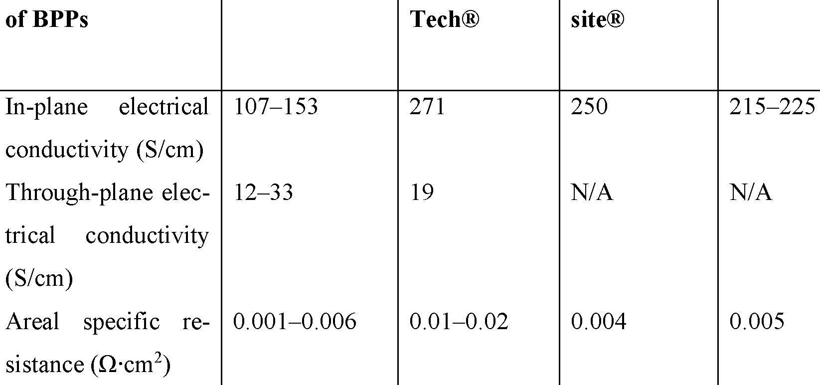
Physical properties of the BPPs with PTFE content lower than 2 wt.% produced accord ing to the method described above have been summarized in Table 2, where the same data from other BPP’s manufacturers are also presented for comparison.
Table 2. Physical properties of BPPs
Physical properties This invention Virginia FJ CompoShin-Etsu®
Figure imgf000016_0001
Density (g/cm3) 2 0 2.2 N/A 2.0 N/A Thickness (mm) 02 1.2 2.0-3.0 N/A 2 0 2.1 When comparing the results as given in Table 2, it is observed that the through-plane conductivity is superior, despite a lower in-plane conductivity. The importance of a low through-plane conductivity was discussed above.

Claims

1. Method of producing a separator plate, the method comprising
- providing a material blend of powder containing at least 70% carbon powder,
10-20% of polyphenylene sulfide, PPS, and 0.005-10% PolyTetraFluoroEthylene, PTFE, all percentages by weight of the sum of the total weight of the powder;
- providing an aqueous suspension with the powder; - heating the carbon/PS S/PTFE suspension to above the glass transition temperature of
124°C of PTFE but below the melting point of PPS for causing fibridization of the PTFE and for causing evaporation of water from the suspension and providing a malleable and pliable substance as a remainder;
- press rolling the malleable and pliable substance into a sheet; characterized in that the method comprises
- hot-compacting the sheet in a press-form at a first pressure PI and at a temperature T to form a separator plate, wherein T is above 220°C and below the melting point of PPS.
2. Method according to claim 1, wherein the method comprises use of water for disper- sion of the powder for providing the aqueous suspension.
3. Method according to claim 2, wherein the method comprises providing the aqueous suspension free of alcohol, for example free of iso-propanol.
4. Method according to any one of the claims 1-3, wherein method comprises deter mining whether the amount of PTFE is higher or lower than 0.1% and providing the suspension with a carbonate ester only if the amount of PTFE is lower than 0.1%, wherein the concentration of the carbonate ester is 0.1-10% relatively to the total con tent of liquid in the suspension.
5. Method according to any one of the claims 1-3, wherein method comprises providing the suspension with carbonate ester at a concentration of 0.1-10% relatively to the total content of liquid in the suspension.
6. Method according to claim 4 or 5, wherein the carbonate ester is propylene car bonate.
7. Method according to claims 4, 5 or 6, wherein method comprises heating the car- bon/PSS/PTFE suspension to a boiling point of carbonate ester for evaporation of the carbonate ester prior to press rolling the malleable and pliable substance into a sheet.
8. Method according to any preceding claim, wherein the method comprises hot-com pacting the separator plate at a first pressure PI in the range of 75 to 325 MPa.
9. Method according to any preceding claim, wherein the separator plate is cooled down in the press-form to below 85°C while maintaining a second pressure P2, wherein P2 is in the range of 20% to 100% of PI.
10. Method according to any preceding claim, wherein the separator plate is a bi polar plate, and the method comprises moulding the sheet into a bipolar plate with a flow channel pattern on each side of the bipolar plate.
11. Method of producing a fuel cell stack, the method comprising, producing a plurality of separator plates by a method according to anyone of the claims 1-10, ar ranging the separator plates as an array with fuel cell membranes between the separator plates, the membranes separating the hydrogen fuel from the oxygen gas.
12. A separator plate for a fuel cell obtainable by a method according to anyone of the preceding claims.
13. A separator plate according to claim 12, wherein the separator plate is a bipo lar plate for a fuel cell.
PCT/DK2020/000242 2019-08-14 2020-08-07 Method of producing separator plates Ceased WO2021027999A1 (en)

Priority Applications (5)

Application Number Priority Date Filing Date Title
EP20852159.1A EP4014268A4 (en) 2019-08-14 2020-08-07 PROCESS FOR PRODUCING SEPARATION PLATES
CN202080056619.8A CN114207889B (en) 2019-08-14 2020-08-07 Methods of producing partitions
US17/635,175 US12040512B2 (en) 2019-08-14 2020-08-07 Method of producing separator plates
JP2022508467A JP7677948B2 (en) 2019-08-14 2020-08-07 Manufacturing method of separator plate
KR1020227008315A KR102873387B1 (en) 2019-08-14 2020-08-07 Method of manufacturing a separator

Applications Claiming Priority (2)

Application Number Priority Date Filing Date Title
DKPA201970518A DK180368B1 (en) 2019-08-14 2019-08-14 Method of producing separator plates
DKPA201970518 2019-08-14

Publications (1)

Publication Number Publication Date
WO2021027999A1 true WO2021027999A1 (en) 2021-02-18

Family

ID=74551290

Family Applications (1)

Application Number Title Priority Date Filing Date
PCT/DK2020/000242 Ceased WO2021027999A1 (en) 2019-08-14 2020-08-07 Method of producing separator plates

Country Status (7)

Country Link
US (1) US12040512B2 (en)
EP (1) EP4014268A4 (en)
JP (1) JP7677948B2 (en)
KR (1) KR102873387B1 (en)
CN (1) CN114207889B (en)
DK (1) DK180368B1 (en)
WO (1) WO2021027999A1 (en)

Cited By (1)

* Cited by examiner, † Cited by third party
Publication number Priority date Publication date Assignee Title
WO2025040225A1 (en) * 2023-08-23 2025-02-27 Blue World Technologies Holding ApS Separator plate, and production method using polymeric binders with high and low mfi and a fuel cell with such separator plate

Families Citing this family (3)

* Cited by examiner, † Cited by third party
Publication number Priority date Publication date Assignee Title
DK180362B1 (en) * 2019-11-05 2021-02-04 Blue World Technologies Holding ApS Method of producing membrane-electrode assemblies and machine therefore
WO2025168187A1 (en) * 2024-02-05 2025-08-14 Blue World Technologies Holding ApS A separator plate and its production as well as production of a precursor, and a fuel cell with such separator
DK182126B1 (en) * 2024-02-05 2025-08-28 Blue World Technologies Holding ApS A separator plate and its production as well as production of a precursor, and a fuel cell with such separator

Citations (5)

* Cited by examiner, † Cited by third party
Publication number Priority date Publication date Assignee Title
US3935029A (en) * 1971-11-18 1976-01-27 Energy Research Corporation Method of fabricating a carbon - polytetrafluoroethylene electrode - support
EP1744389A1 (en) * 2005-07-14 2007-01-17 Aisin Seiki Kabushiki Kaisha Fuel cell separator and method of manufacturing the same
CN101174695A (en) * 2007-10-24 2008-05-07 山东大学 Bipolar plate for phosphoric acid fuel cell and preparation method thereof
WO2018072803A1 (en) * 2016-10-19 2018-04-26 Serenergy A/S A method for producing a separator plate for a fuel cell and a method for producing a fuel cell stack with such separator
WO2020103345A1 (en) * 2018-11-19 2020-05-28 众安信息技术服务有限公司 Session flow processing method and apparatus, and computer-readable storage medium

Family Cites Families (11)

* Cited by examiner, † Cited by third party
Publication number Priority date Publication date Assignee Title
US6544680B1 (en) 1999-06-14 2003-04-08 Kawasaki Steel Corporation Fuel cell separator, a fuel cell using the fuel cell separator, and a method for making the fuel cell separator
JP2002025340A (en) 2000-07-04 2002-01-25 Nisshinbo Ind Inc Conductive resin composition, fuel cell separator, method for producing the same, and polymer electrolyte fuel cell
FR2822296A1 (en) * 2001-03-19 2002-09-20 Atofina Separators and electroactive layers for lithium batteries, produced by shaping a microcomposite powder comprising a filler and a finely divided fluoropolymer
KR100759654B1 (en) 2004-05-31 2007-09-17 마츠시타 덴끼 산교 가부시키가이샤 Polyelectrolyte fuel cell-use separator, polyelectrolyte fuel cell, method of evaluating polyelectrolyte fuel cell-use separator, and production method of polyelectrolyte fuel cell-use separator
WO2006095821A1 (en) 2005-03-10 2006-09-14 Bridgestone Corporation Thermoplastic resin composition and thermoplastic resin molded article
JP5766106B2 (en) * 2011-12-08 2015-08-19 信越ポリマー株式会社 Water repellent fuel cell separator and method for producing the same
US10766173B2 (en) 2012-01-05 2020-09-08 Audi Ag Method of manufacturing multiple fuel cell separator plate assemblies
WO2014007397A1 (en) 2012-07-06 2014-01-09 ダイキン工業株式会社 Sheet, electrode and fuel cell
KR101815134B1 (en) * 2015-01-02 2018-01-05 한국타이어 주식회사 Fuel cell separator plate and fabrication method thereof
KR20180135344A (en) 2017-06-12 2018-12-20 주식회사 모간 The control of carbon materials structure on bipolar plate for fuel cell and its manufacturing method
JP6972772B2 (en) 2017-08-24 2021-11-24 日清紡ホールディングス株式会社 Fuel cell separator precursor and fuel cell separator

Patent Citations (5)

* Cited by examiner, † Cited by third party
Publication number Priority date Publication date Assignee Title
US3935029A (en) * 1971-11-18 1976-01-27 Energy Research Corporation Method of fabricating a carbon - polytetrafluoroethylene electrode - support
EP1744389A1 (en) * 2005-07-14 2007-01-17 Aisin Seiki Kabushiki Kaisha Fuel cell separator and method of manufacturing the same
CN101174695A (en) * 2007-10-24 2008-05-07 山东大学 Bipolar plate for phosphoric acid fuel cell and preparation method thereof
WO2018072803A1 (en) * 2016-10-19 2018-04-26 Serenergy A/S A method for producing a separator plate for a fuel cell and a method for producing a fuel cell stack with such separator
WO2020103345A1 (en) * 2018-11-19 2020-05-28 众安信息技术服务有限公司 Session flow processing method and apparatus, and computer-readable storage medium

Non-Patent Citations (1)

* Cited by examiner, † Cited by third party
Title
See also references of EP4014268A4 *

Cited By (3)

* Cited by examiner, † Cited by third party
Publication number Priority date Publication date Assignee Title
WO2025040225A1 (en) * 2023-08-23 2025-02-27 Blue World Technologies Holding ApS Separator plate, and production method using polymeric binders with high and low mfi and a fuel cell with such separator plate
DK202330161A1 (en) * 2023-08-23 2025-05-15 Blue World Technologies Holding ApS Separator plate, and production method using thermoplastic polymer with high and low-MFI as binder and a fuel cell with such separator plate
DK181995B1 (en) * 2023-08-23 2025-05-15 Blue World Technologies Holding ApS Separator plate, and production method using thermoplastic polymer with high and low-MFI as binder and a fuel cell with such separator plate

Also Published As

Publication number Publication date
US12040512B2 (en) 2024-07-16
DK180368B1 (en) 2021-02-09
EP4014268A4 (en) 2024-09-25
US20220293969A1 (en) 2022-09-15
CN114207889A (en) 2022-03-18
JP7677948B2 (en) 2025-05-15
JP2022544222A (en) 2022-10-17
EP4014268A1 (en) 2022-06-22
KR102873387B1 (en) 2025-10-17
DK201970518A1 (en) 2021-02-09
KR20220048002A (en) 2022-04-19
CN114207889B (en) 2023-12-26

Similar Documents

Publication Publication Date Title
US12040512B2 (en) Method of producing separator plates
US11559926B2 (en) Method of producing separator plates by compaction and a production facility
US20030180597A1 (en) Conductive composition for solid polymer type fuel cell separator, solid polymer type fuel cell separator, solid polymer type fuel cell and solid polymer type fuel cell system using the separator
US20090317666A1 (en) Hydrophilic Carbon Black Aggregate, A Method for Preparing the Same, Hydrophilic Composite Material and Bipolar Plate for Fuel Cell Comprising the Same
EP2871697A1 (en) Sheet, electrode and fuel cell
CN102473930A (en) Manufacturing method of fuel cell separator
EP1968143B1 (en) Process for producing separator material for polymer electrolyte fuel cells
US20100035094A1 (en) Hydrophilic Inorganic Aggregate, A Method for Preparing the Same, Hydrophilic Composite Material and Bipolar Plate for Fuel Cell Comprising the Same
JP5019195B2 (en) Method for producing separator material for fuel cell
JP2003297382A (en) Fuel cell separator
KR101573061B1 (en) resin composition for bipolar plate and method of manufacturing of bipolar plate by injection molding
JP2003297381A (en) Fuel cell separator
JP4733008B2 (en) Conductive resin molded body and method for producing the same
KR102340427B1 (en) Composite for fuel cell bipolar plate and its preparation method
WO2025079699A1 (en) Gas diffusion layer and method for manufacturing same, powder for gas diffusion layer, membrane electrode assembly, and fuel cell
KR20220159182A (en) Method for preparing separator
KR20160082868A (en) carbon composite for polymer electrolyte membrane fuel cell and the preparing method thereof
JP2005158659A (en) Separator material for polymer electrolyte fuel cell and manufacturing method thereof
JP2007145023A (en) Electric-conductive resin molded article and its production method
JP2008186642A (en) Fuel battery separator
JPWO2002001660A1 (en) Conductive composition for polymer electrolyte fuel cell separator, polymer electrolyte fuel cell separator, polymer electrolyte fuel cell and polymer electrolyte fuel cell system using said separator

Legal Events

Date Code Title Description
121 Ep: the epo has been informed by wipo that ep was designated in this application

Ref document number: 20852159

Country of ref document: EP

Kind code of ref document: A1

ENP Entry into the national phase

Ref document number: 2022508467

Country of ref document: JP

Kind code of ref document: A

NENP Non-entry into the national phase

Ref country code: DE

ENP Entry into the national phase

Ref document number: 20227008315

Country of ref document: KR

Kind code of ref document: A

ENP Entry into the national phase

Ref document number: 2020852159

Country of ref document: EP

Effective date: 20220314