WO2021029014A1 - 電磁鋼板 - Google Patents
電磁鋼板 Download PDFInfo
- Publication number
- WO2021029014A1 WO2021029014A1 PCT/JP2019/031854 JP2019031854W WO2021029014A1 WO 2021029014 A1 WO2021029014 A1 WO 2021029014A1 JP 2019031854 W JP2019031854 W JP 2019031854W WO 2021029014 A1 WO2021029014 A1 WO 2021029014A1
- Authority
- WO
- WIPO (PCT)
- Prior art keywords
- steel sheet
- face
- electromagnetic steel
- layer
- nitrided layer
- Prior art date
- Legal status (The legal status is an assumption and is not a legal conclusion. Google has not performed a legal analysis and makes no representation as to the accuracy of the status listed.)
- Ceased
Links
Images




Classifications
-
- C—CHEMISTRY; METALLURGY
- C21—METALLURGY OF IRON
- C21D—MODIFYING THE PHYSICAL STRUCTURE OF FERROUS METALS; GENERAL DEVICES FOR HEAT TREATMENT OF FERROUS OR NON-FERROUS METALS OR ALLOYS; MAKING METAL MALLEABLE, e.g. BY DECARBURISATION OR TEMPERING
- C21D9/00—Heat treatment, e.g. annealing, hardening, quenching or tempering, adapted for particular articles; Furnaces therefor
- C21D9/46—Heat treatment, e.g. annealing, hardening, quenching or tempering, adapted for particular articles; Furnaces therefor for sheet metals
-
- H—ELECTRICITY
- H01—ELECTRIC ELEMENTS
- H01F—MAGNETS; INDUCTANCES; TRANSFORMERS; SELECTION OF MATERIALS FOR THEIR MAGNETIC PROPERTIES
- H01F1/00—Magnets or magnetic bodies characterised by the magnetic materials therefor; Selection of materials for their magnetic properties
- H01F1/01—Magnets or magnetic bodies characterised by the magnetic materials therefor; Selection of materials for their magnetic properties of inorganic materials
- H01F1/03—Magnets or magnetic bodies characterised by the magnetic materials therefor; Selection of materials for their magnetic properties of inorganic materials characterised by their coercivity
- H01F1/12—Magnets or magnetic bodies characterised by the magnetic materials therefor; Selection of materials for their magnetic properties of inorganic materials characterised by their coercivity of soft-magnetic materials
- H01F1/14—Magnets or magnetic bodies characterised by the magnetic materials therefor; Selection of materials for their magnetic properties of inorganic materials characterised by their coercivity of soft-magnetic materials metals or alloys
- H01F1/147—Alloys characterised by their composition
-
- C—CHEMISTRY; METALLURGY
- C21—METALLURGY OF IRON
- C21D—MODIFYING THE PHYSICAL STRUCTURE OF FERROUS METALS; GENERAL DEVICES FOR HEAT TREATMENT OF FERROUS OR NON-FERROUS METALS OR ALLOYS; MAKING METAL MALLEABLE, e.g. BY DECARBURISATION OR TEMPERING
- C21D1/00—General methods or devices for heat treatment, e.g. annealing, hardening, quenching or tempering
- C21D1/06—Surface hardening
-
- C—CHEMISTRY; METALLURGY
- C21—METALLURGY OF IRON
- C21D—MODIFYING THE PHYSICAL STRUCTURE OF FERROUS METALS; GENERAL DEVICES FOR HEAT TREATMENT OF FERROUS OR NON-FERROUS METALS OR ALLOYS; MAKING METAL MALLEABLE, e.g. BY DECARBURISATION OR TEMPERING
- C21D8/00—Modifying the physical properties of ferrous metals or ferrous alloys by deformation combined with, or followed by, heat treatment
- C21D8/12—Modifying the physical properties of ferrous metals or ferrous alloys by deformation combined with, or followed by, heat treatment during manufacturing of articles with special electromagnetic properties
- C21D8/1244—Modifying the physical properties of ferrous metals or ferrous alloys by deformation combined with, or followed by, heat treatment during manufacturing of articles with special electromagnetic properties characterised by the heat treatment
- C21D8/1255—Modifying the physical properties of ferrous metals or ferrous alloys by deformation combined with, or followed by, heat treatment during manufacturing of articles with special electromagnetic properties characterised by the heat treatment with diffusion of elements, e.g. decarburising, nitriding
-
- C—CHEMISTRY; METALLURGY
- C22—METALLURGY; FERROUS OR NON-FERROUS ALLOYS; TREATMENT OF ALLOYS OR NON-FERROUS METALS
- C22C—ALLOYS
- C22C38/00—Ferrous alloys, e.g. steel alloys
- C22C38/02—Ferrous alloys, e.g. steel alloys containing silicon
-
- C—CHEMISTRY; METALLURGY
- C22—METALLURGY; FERROUS OR NON-FERROUS ALLOYS; TREATMENT OF ALLOYS OR NON-FERROUS METALS
- C22C—ALLOYS
- C22C38/00—Ferrous alloys, e.g. steel alloys
- C22C38/04—Ferrous alloys, e.g. steel alloys containing manganese
-
- C—CHEMISTRY; METALLURGY
- C22—METALLURGY; FERROUS OR NON-FERROUS ALLOYS; TREATMENT OF ALLOYS OR NON-FERROUS METALS
- C22C—ALLOYS
- C22C38/00—Ferrous alloys, e.g. steel alloys
- C22C38/06—Ferrous alloys, e.g. steel alloys containing aluminium
-
- C—CHEMISTRY; METALLURGY
- C22—METALLURGY; FERROUS OR NON-FERROUS ALLOYS; TREATMENT OF ALLOYS OR NON-FERROUS METALS
- C22C—ALLOYS
- C22C38/00—Ferrous alloys, e.g. steel alloys
- C22C38/08—Ferrous alloys, e.g. steel alloys containing nickel
-
- C—CHEMISTRY; METALLURGY
- C23—COATING METALLIC MATERIAL; COATING MATERIAL WITH METALLIC MATERIAL; CHEMICAL SURFACE TREATMENT; DIFFUSION TREATMENT OF METALLIC MATERIAL; COATING BY VACUUM EVAPORATION, BY SPUTTERING, BY ION IMPLANTATION OR BY CHEMICAL VAPOUR DEPOSITION, IN GENERAL; INHIBITING CORROSION OF METALLIC MATERIAL OR INCRUSTATION IN GENERAL
- C23C—COATING METALLIC MATERIAL; COATING MATERIAL WITH METALLIC MATERIAL; SURFACE TREATMENT OF METALLIC MATERIAL BY DIFFUSION INTO THE SURFACE, BY CHEMICAL CONVERSION OR SUBSTITUTION; COATING BY VACUUM EVAPORATION, BY SPUTTERING, BY ION IMPLANTATION OR BY CHEMICAL VAPOUR DEPOSITION, IN GENERAL
- C23C8/00—Solid state diffusion of only non-metal elements into metallic material surfaces; Chemical surface treatment of metallic material by reaction of the surface with a reactive gas, leaving reaction products of surface material in the coating, e.g. conversion coatings, passivation of metals
- C23C8/06—Solid state diffusion of only non-metal elements into metallic material surfaces; Chemical surface treatment of metallic material by reaction of the surface with a reactive gas, leaving reaction products of surface material in the coating, e.g. conversion coatings, passivation of metals using gases
- C23C8/08—Solid state diffusion of only non-metal elements into metallic material surfaces; Chemical surface treatment of metallic material by reaction of the surface with a reactive gas, leaving reaction products of surface material in the coating, e.g. conversion coatings, passivation of metals using gases only one element being applied
- C23C8/24—Nitriding
- C23C8/26—Nitriding of ferrous surfaces
-
- C—CHEMISTRY; METALLURGY
- C23—COATING METALLIC MATERIAL; COATING MATERIAL WITH METALLIC MATERIAL; CHEMICAL SURFACE TREATMENT; DIFFUSION TREATMENT OF METALLIC MATERIAL; COATING BY VACUUM EVAPORATION, BY SPUTTERING, BY ION IMPLANTATION OR BY CHEMICAL VAPOUR DEPOSITION, IN GENERAL; INHIBITING CORROSION OF METALLIC MATERIAL OR INCRUSTATION IN GENERAL
- C23C—COATING METALLIC MATERIAL; COATING MATERIAL WITH METALLIC MATERIAL; SURFACE TREATMENT OF METALLIC MATERIAL BY DIFFUSION INTO THE SURFACE, BY CHEMICAL CONVERSION OR SUBSTITUTION; COATING BY VACUUM EVAPORATION, BY SPUTTERING, BY ION IMPLANTATION OR BY CHEMICAL VAPOUR DEPOSITION, IN GENERAL
- C23C8/00—Solid state diffusion of only non-metal elements into metallic material surfaces; Chemical surface treatment of metallic material by reaction of the surface with a reactive gas, leaving reaction products of surface material in the coating, e.g. conversion coatings, passivation of metals
- C23C8/06—Solid state diffusion of only non-metal elements into metallic material surfaces; Chemical surface treatment of metallic material by reaction of the surface with a reactive gas, leaving reaction products of surface material in the coating, e.g. conversion coatings, passivation of metals using gases
- C23C8/28—Solid state diffusion of only non-metal elements into metallic material surfaces; Chemical surface treatment of metallic material by reaction of the surface with a reactive gas, leaving reaction products of surface material in the coating, e.g. conversion coatings, passivation of metals using gases more than one element being applied in one step
- C23C8/30—Carbo-nitriding
- C23C8/32—Carbo-nitriding of ferrous surfaces
-
- H—ELECTRICITY
- H01—ELECTRIC ELEMENTS
- H01F—MAGNETS; INDUCTANCES; TRANSFORMERS; SELECTION OF MATERIALS FOR THEIR MAGNETIC PROPERTIES
- H01F1/00—Magnets or magnetic bodies characterised by the magnetic materials therefor; Selection of materials for their magnetic properties
- H01F1/01—Magnets or magnetic bodies characterised by the magnetic materials therefor; Selection of materials for their magnetic properties of inorganic materials
- H01F1/03—Magnets or magnetic bodies characterised by the magnetic materials therefor; Selection of materials for their magnetic properties of inorganic materials characterised by their coercivity
- H01F1/12—Magnets or magnetic bodies characterised by the magnetic materials therefor; Selection of materials for their magnetic properties of inorganic materials characterised by their coercivity of soft-magnetic materials
- H01F1/14—Magnets or magnetic bodies characterised by the magnetic materials therefor; Selection of materials for their magnetic properties of inorganic materials characterised by their coercivity of soft-magnetic materials metals or alloys
- H01F1/16—Magnets or magnetic bodies characterised by the magnetic materials therefor; Selection of materials for their magnetic properties of inorganic materials characterised by their coercivity of soft-magnetic materials metals or alloys in the form of sheets
-
- H—ELECTRICITY
- H01—ELECTRIC ELEMENTS
- H01F—MAGNETS; INDUCTANCES; TRANSFORMERS; SELECTION OF MATERIALS FOR THEIR MAGNETIC PROPERTIES
- H01F1/00—Magnets or magnetic bodies characterised by the magnetic materials therefor; Selection of materials for their magnetic properties
- H01F1/01—Magnets or magnetic bodies characterised by the magnetic materials therefor; Selection of materials for their magnetic properties of inorganic materials
- H01F1/03—Magnets or magnetic bodies characterised by the magnetic materials therefor; Selection of materials for their magnetic properties of inorganic materials characterised by their coercivity
- H01F1/12—Magnets or magnetic bodies characterised by the magnetic materials therefor; Selection of materials for their magnetic properties of inorganic materials characterised by their coercivity of soft-magnetic materials
- H01F1/14—Magnets or magnetic bodies characterised by the magnetic materials therefor; Selection of materials for their magnetic properties of inorganic materials characterised by their coercivity of soft-magnetic materials metals or alloys
- H01F1/16—Magnets or magnetic bodies characterised by the magnetic materials therefor; Selection of materials for their magnetic properties of inorganic materials characterised by their coercivity of soft-magnetic materials metals or alloys in the form of sheets
- H01F1/18—Magnets or magnetic bodies characterised by the magnetic materials therefor; Selection of materials for their magnetic properties of inorganic materials characterised by their coercivity of soft-magnetic materials metals or alloys in the form of sheets with insulating coating
-
- C—CHEMISTRY; METALLURGY
- C21—METALLURGY OF IRON
- C21D—MODIFYING THE PHYSICAL STRUCTURE OF FERROUS METALS; GENERAL DEVICES FOR HEAT TREATMENT OF FERROUS OR NON-FERROUS METALS OR ALLOYS; MAKING METAL MALLEABLE, e.g. BY DECARBURISATION OR TEMPERING
- C21D2221/00—Treating localised areas of an article
- C21D2221/02—Edge parts
-
- Y—GENERAL TAGGING OF NEW TECHNOLOGICAL DEVELOPMENTS; GENERAL TAGGING OF CROSS-SECTIONAL TECHNOLOGIES SPANNING OVER SEVERAL SECTIONS OF THE IPC; TECHNICAL SUBJECTS COVERED BY FORMER USPC CROSS-REFERENCE ART COLLECTIONS [XRACs] AND DIGESTS
- Y02—TECHNOLOGIES OR APPLICATIONS FOR MITIGATION OR ADAPTATION AGAINST CLIMATE CHANGE
- Y02T—CLIMATE CHANGE MITIGATION TECHNOLOGIES RELATED TO TRANSPORTATION
- Y02T10/00—Road transport of goods or passengers
- Y02T10/60—Other road transportation technologies with climate change mitigation effect
- Y02T10/64—Electric machine technologies in electromobility
Definitions
- the present invention relates to an electromagnetic steel sheet, and more particularly to an electromagnetic steel sheet applicable to a rotor of a drive motor mounted on an electric vehicle or the like.
- This high-strength non-directional electromagnetic steel plate has C: more than 0.0050% by mass and 0.020% by mass or less, N: 0.01% by mass or less, (C + N): 0.030% by mass or less, Si: 4.0. It contains more than mass% and 10.0% by mass or less, Cr: 2.0 to 10.0% by mass, and P: 0.04% by mass or less.
- This high-strength non-oriented electrical steel sheet further contains Ti satisfying the equation (1): ⁇ 0.02 ⁇ Ti-4 (C + N) ⁇ 0.04, and the balance is Fe and unavoidable impurities.
- An object of the present invention is to provide an electromagnetic steel sheet having improved fatigue strength by 10% or more without significantly lowering the magnetic properties.
- the present inventors have made extensive studies to achieve the above object. As a result, they have found that the above object can be achieved by providing a predetermined nitride layer on the end face of the electromagnetic steel sheet, and have completed the present invention.
- the electromagnetic steel sheet of the present invention has a main surface and an end surface.
- the electrical steel sheet includes a base material portion and a nitrogen-containing end face nitrided layer adjacent to the base metal portion and provided on the end face.
- the surface hardness of the end face nitrided layer is 430 HV or more and 1250 HV or less.
- the present invention since a predetermined nitrided layer is provided on the end face of the electromagnetic steel sheet, it is possible to provide an electromagnetic steel sheet having improved fatigue strength by 10% or more without significantly reducing the magnetic characteristics.
- FIG. 1 is a perspective view showing an outline of an electromagnetic steel sheet according to a first embodiment.
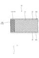
- FIG. 2 is a schematic cross-sectional view taken along line II-II of the electromagnetic steel sheet shown in FIG.
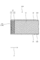
- FIG. 3 is a schematic cross-sectional view showing a main part of the electromagnetic steel plate according to the second embodiment.
- FIG. 4 is a schematic cross-sectional view showing a main part of the electromagnetic steel plate according to the third embodiment.
- FIG. 5 is a schematic cross-sectional view showing a main part of the electromagnetic steel plate according to the fourth embodiment.
- FIG. 6 is a schematic cross-sectional view showing a main part of the electromagnetic steel plate according to the fifth embodiment.
- FIG. 7 is a schematic cross-sectional view showing a main part of the electromagnetic steel plate according to the sixth embodiment.
- FIG. 8 is a schematic cross-sectional view showing a main part of the electromagnetic steel plate according to the seventh embodiment.
- FIG. 1 is a perspective view showing an outline of an electromagnetic steel sheet according to a first embodiment.
- FIG. 2 is a schematic cross-sectional view taken along line II-II of the electromagnetic steel sheet shown in FIG.
- the electromagnetic steel sheet 10 of the first embodiment has a main surface 10a and end surfaces 10b and 10b.
- the electrical steel sheet 10 includes a base material portion 11 and an end face nitrided layer 13 adjacent to the base metal portion and provided on the end face 10b.
- the electromagnetic steel sheet 10 preferably includes insulating coatings 15 and 15 formed on the main surfaces 10a and 10a of the electrical steel sheet.
- the end face nitrided layer contains nitrogen.
- the surface hardness of the end face nitrided layer is 430 HV or more and 1250 HV or less.
- the "end face” means an end face processed into a shape according to the shape of the part and the purpose of use.
- the surface hardness of the end face nitrided layer provided on the end face of the electromagnetic steel sheet is 430 HV or more and 1250 HV or less, so that the magnetic characteristics of the electromagnetic steel sheet are significantly lowered.
- the fatigue strength of the electrical steel sheet is improved by 10% or more.
- the surface hardness of the end face nitrided layer is less than 430 HV, the fatigue strength of the electrical steel sheet cannot be improved by 10% or more.
- the surface hardness of the end face nitrided layer is larger than 1250 HV, the magnetic characteristics of the electrical steel sheet are significantly deteriorated. More specifically, when the surface hardness of the end face nitrided layer is larger than 1250 HV, the iron loss of the electrical steel sheet becomes remarkably large.
- the "surface hardness of the end face nitrided layer" is measured in accordance with the Japanese Industrial Standards Vickers hardness test-test method (JIS Z 2244). However, if the end face has a shear plane, which will be described later, the measurement is performed in the region of the shear plane.
- Gas soft nitriding or acid nitriding is performed on the end face of the electrical steel sheet with the gas used, processing temperature, and processing time controlled. Nitrogen is diffused from the end face of the electromagnetic steel sheet, and an end face nitrided layer containing nitrogen and having a surface hardness of 430 HV or more and 1250 HV or less is formed on the electromagnetic steel sheet. As a result, the fatigue strength near the end face of the electromagnetic steel sheet, which is the starting point of fatigue fracture, can be improved.
- the gas used for gas nitrocarburizing is not particularly limited, but for example, ammonia (NH 3 ) / carbon dioxide (CO 2 ) is preferably applied.
- the treatment temperature of gas nitrocarburizing is not particularly limited, but is preferably 490 ° C. or higher and 560 ° C. or lower, and more preferably 500 ° C. or higher and 540 ° C. or lower.
- the treatment time for gas nitrocarburizing is not particularly limited, but is preferably 0.5 hours or more and 4 hours or less, more preferably 0.5 hours or more and 3.5 hours or less, and further preferably 1 hour or more and 3 hours or less. Especially preferably 1 hour or more and 2.5 hours or less.
- the gas used for oxynitriding is not particularly limited, but for example, ammonia (NH 3 ) / air (Air) is preferably applied.
- the oxynitriding treatment temperature is not particularly limited, but is preferably 450 ° C. or higher and 480 ° C. or lower, more preferably 455 ° C. or higher and 465 ° C. or lower, and further preferably 460 ° C. or higher and 465 ° C. or lower.
- the oxynitriding treatment time is not particularly limited, but is preferably 0.5 hours or more and 4 hours or less, more preferably 1 hour or more and 3.5 hours or less, and further preferably 1.5 hours or more and 3.5 hours or less. , 1.5 hours or more and 3 hours or less is particularly preferable.
- iron loss (W 15/50 ) and iron loss (W 10/400 ) are measured as magnetic characteristics.
- W 15/50 means iron loss per 1 kg of electrical steel sheet at a maximum magnetic flux density of 1.5 T and a frequency of 50 Hz
- W 10/400 means an electromagnetic steel sheet of 1 kg at a maximum magnetic flux density of 1.0 T and a frequency of 400 Hz. It means the iron loss per hit.
- the iron loss becomes significantly large means that the increase in the iron loss of the gas-nitrided or oxynitrided electromagnetic steel sheet exceeds 60% with respect to the above-mentioned gas-nitrided or oxynitrided electromagnetic steel sheet. means.
- the iron loss becomes remarkably large means the iron loss ratio of the gas soft nitriding or oxynitriding electromagnetic steel sheet to the above-mentioned non-gas nitrocarburizing or oxynitriding electromagnetic steel sheet (W 15 /). 50 ) and the iron loss ratio (W 10/400 ) exceed 1.60.
- the composition of the electromagnetic steel plate 10 is not particularly limited, but for example, silicon (Si): 2.0% by mass or more and 4.0% by mass or less, aluminum (Al): 0.15% by mass or more and 2.00% by mass or less. , Manganese (Mn): 0.10% by mass or more and 2.00% by mass or less, Nickel (Ni): 0.01% by mass or more and 3.0% by mass or less, and the balance is iron (Fe) and unavoidable impurities. It is preferable to apply a certain electromagnetic steel plate.
- the thickness of the electrical steel sheet 10 is not particularly limited, but is preferably 0.5 mm or less, more preferably 0.15 mm or more and 0.5 mm or less, and 0.15 mm or more and 0.35 mm or less. Is more preferable.
- the end face 10b is not particularly limited, but is preferably a cut end face, for example.
- the cut end face examples include a cut end face machined by a wire-cut electric discharge machine.
- the cut end face machined by the wire-cut electric discharge machine may be further lapping.
- the end face has a cut end face machined by a wire-cut electric discharge machine
- the iron in the electrical steel sheet is compared with the case where the end face has a punched end face having at least a sheared surface machined by a press working machine described later. The loss is unlikely to increase.
- the end face has a punched end face, there is an advantage that the productivity when mass-producing the electromagnetic steel sheet having the end face is higher than the case where the end face has a cut end face machined by a wire-cut electric discharge machine. There is.
- the end face nitrided layer 13 is not particularly limited as long as it has a surface hardness of 430 HV or more and 1250 HV or less, but is, for example, an end face nitrided layer formed by gas nitriding or oxynitriding of the end face of the above-mentioned electromagnetic steel sheet. Is preferable.
- the base material portion 11 is a portion in a state of being rolled to a predetermined thickness according to the shape of the part and the purpose of use, and the composition of the base material is changed by the above-mentioned treatment such as gas nitrocarburizing or nitriding such as acid nitriding. It is a part that has not been formed or is not deformed by processing such as punching. Further, the base metal portion is located on the central side of the main surface in the surface direction.
- the insulating coating 15 is not particularly limited as long as it has electrical insulating properties, but for example, it is preferable to apply an insulating coating made of a conventionally known inorganic material or organic material or a mixture thereof. Needless to say, the electromagnetic steel sheet not provided with the insulating coating 15 is also included in the scope of the present invention.
- the nitrogen concentration on the end face is higher than the nitrogen concentration on the main surface.
- the electrical steel sheet has a nitrogen concentration on the end face higher than the nitrogen concentration on the main surface and the surface hardness of the end face nitrided layer is 430 HV or more and 1250 HV or less, the deterioration of the magnetic properties of the electrical steel sheet is further suppressed, and the electrical steel sheet is further suppressed. Fatigue strength is improved by 10% or more. Further, there is an advantage that the electromagnetic steel sheet is less likely to be distorted.
- the magnitude relationship between the "nitrogen concentration on the end face” and the “nitrogen concentration on the main surface” can be specified by measuring the nitrogen distribution by electron probe microanalyzer analysis in the cross section along the thickness direction of the electromagnetic steel plate.
- the "nitrogen concentration on the main surface” is measured at a position where the depth from the end face in the depth direction of the end face nitrided layer is 500 ⁇ m.
- the depth is 40 ⁇ m from the surface 13a of the end face nitrided layer 13 in the cross section along the depth direction of the end face nitrided layer 13 (indicated by the arrow Z in FIG. 2) with respect to the surface hardness of the end face nitrided layer 13.
- the ratio of hardness at the position is preferably 80% or less.
- the diffusion range of nitrogen which is a factor for improving fatigue strength, in other words, the hardness increase range is narrowed, so that the magnetic properties of the electrical steel sheet are further deteriorated.
- the fatigue strength of the electrical steel sheet is improved by 10% or more.
- the increase in iron loss (W 15/50 and W 10/400 ) of the electrical steel sheet is suppressed to 10% or less, and the fatigue strength of the electrical steel sheet is improved by 10% or more. It is possible.
- the surface hardness of the end face nitrided layer 13 is preferably 550 HV or more, and more preferably 550 HV or more and 950 HV or less.
- an electromagnetic steel sheet having a surface hardness of the end face nitrided layer of 550 HV or more deterioration of the magnetic characteristics of the electromagnetic steel sheet is further suppressed, and the fatigue strength of the electromagnetic steel sheet is improved by 10% or more.
- the increase in iron loss (W 15/50 and W 10/400 ) of the electrical steel sheet is suppressed to 10% or less, and the fatigue strength of the electrical steel sheet is improved by 10% or more. It is possible.
- the distance from the surface 13a of the end face nitrided layer 13 in the depth direction of the end face nitrided layer 13 to the point of the Vickers hardness value 50 higher than the Vickers hardness value of the base metal portion 11 is 0. It is preferably 07 mm or more, and more preferably 0.07 mm or more and 0.14 mm or less.
- the distance from the surface of the end face nitrided layer in the depth direction of the end face nitrided layer to the point of the Vickers hardness value 50 higher than the Vickers hardness value of the base metal portion is defined as "practical nitrided layer depth".
- the "practical nitride layer depth” is measured in accordance with the Japanese Industrial Standards steel nitride layer depth measurement method (JIS G 0562). However, if the end face has a shear plane, which will be described later, the measurement is performed in the region of the shear plane.
- the end face nitrided layer 13 is preferably made of a diffusion layer 133.
- the end face nitrided layer does not have a compound layer containing an iron nitrogen compound and an iron carbon dioxide nitrogen compound. Since the end face nitrided layer does not have a compound layer, the notch sensitivity does not increase and the fatigue strength of the electrical steel sheet is improved.
- the nitrogen compound of iron include ⁇ '-Fe 4 N, ⁇ -Fe 2 N, and ⁇ -Fe 3 N.
- the presence or absence of the compound layer can be identified by observing the cross section with a scanning electron microscope and further performing elemental analysis by energy dispersive X-ray analysis.
- an electromagnetic steel sheet in which the end face nitrided layer is a diffusion layer, deterioration of the magnetic properties of the electrical steel sheet is further suppressed, and the fatigue strength of the electrical steel sheet is improved by 10% or more.
- the increase in iron loss (W 15/50 and W 10/400 ) of the electrical steel sheet is suppressed to 10% or less, and the fatigue strength of the electrical steel sheet is improved by 10% or more. It is possible.
- the thickness of the electrical steel sheet in the end face nitrided layer is preferably equal to or less than the thickness of the electrical steel sheet in the base metal portion, and more preferably smaller than the thickness of the electrical steel sheet in the base metal portion.
- the core of a rotor is formed by laminating electromagnetic steel sheets. Therefore, in such an application, it is preferable that there is a relationship of the above thickness.
- FIG. 3 is a schematic cross-sectional view showing a main part of the electromagnetic steel plate according to the second embodiment. Note that FIG. 3 is a schematic cross-sectional view of the same portion as the portion shown by line II-II shown in FIG. 1 of the electromagnetic steel sheet according to the second embodiment.
- the components equivalent to those described in the above-described embodiment are designated by the same reference numerals and the description thereof will be omitted.
- the electromagnetic steel sheet 10A according to the second embodiment is different from the electrical steel sheet 10 according to the first embodiment in that the end face nitrided layer 13 includes the compound layer 131 and the diffusion layer 133. There is.
- the electromagnetic steel sheet of the second embodiment since the surface hardness of the end face nitrided layer provided on the end face of the electromagnetic steel sheet is 430 HV or more and 1250 HV or less, the magnetic characteristics are not significantly deteriorated and fatigue occurs. Strength is improved by 10% or more. Further, in the electromagnetic steel sheet of the second embodiment, the end face nitrided layer includes a compound layer and a diffusion layer. In such an electromagnetic steel sheet, deterioration of magnetic properties is further suppressed, and fatigue strength is improved by 10% or more.
- the compound layer will be described in more detail.
- Examples of the compound layer 131 include a compound layer containing an iron nitrogen compound and an iron carbon dioxide compound.
- Examples of the nitrogen compound of iron include ⁇ '-Fe 4 N, ⁇ -Fe 2 N, and ⁇ -Fe 3 N.
- Such a compound layer has high hardness, it is generally effective in improving the fatigue strength of electrical steel sheets.
- the preferred embodiment described in the electromagnetic steel sheet 10 according to the first embodiment described above can be appropriately adopted.
- FIG. 4 is a schematic cross-sectional view showing a main part of the electromagnetic steel plate according to the third embodiment. Note that FIG. 4 is a schematic cross-sectional view of the same portion as the portion shown by the line II-II shown in FIG. 1 of the electromagnetic steel sheet according to the third embodiment.
- the components equivalent to those described in the above-described embodiment are designated by the same reference numerals and the description thereof will be omitted.
- the ratio of the compound layer 131 to the surface 13a of the end face nitrided layer 13 is 50% or less, which is the electromagnetic steel according to the second embodiment. It is different from the steel plate 10A.
- the surface hardness of the end face nitrided layer provided on the end face of the electromagnetic steel sheet is 430 HV or more and 1250 HV or less, so that the magnetic characteristics are not significantly deteriorated and fatigue occurs. Strength is improved by 10% or more.
- the end face nitrided layer includes a compound layer and a diffusion layer. In such an electromagnetic steel sheet, deterioration of magnetic properties is further suppressed, and fatigue strength is improved by 10% or more.
- the ratio of the compound layer to the surface of the end face nitrided layer is 50% or less, preferably 40% or less, more preferably 30% or less, still more preferably 20% or less, particularly. It is preferably 10% or less.
- deterioration of the magnetic characteristics of the electromagnetic steel sheet is further suppressed, and the fatigue strength of the electromagnetic steel sheet is improved by 10% or more.
- the "ratio of the compound layer to the surface of the end face nitrided layer” is a compound with respect to the length of the contour line defining the surface of the end face nitrogen layer on the end face observed in the cross section along the thickness direction of the electrical steel sheet. It means the ratio of the lengths of contour lines that define the surface of the layer.
- the compound layer has high hardness, it is generally effective in improving the fatigue strength of electrical steel sheets.
- the compound layer is brittle, cracks are likely to occur due to repeated input. When a crack is generated by repeated input, it causes fatigue fracture in which the crack gradually progresses starting from the crack. Since the residual cross-sectional area of the cross section of the crack extension portion is reduced, the stress applied to the cross section is conversely increased. Since the magnetic steel sheet is thin, the cross section of the crack growth part is easily affected by the stress increase, and the yield strength of the material is exceeded from the early stage to the middle stage of the crack generation, so the number of repetitions from the crack generation to the fracture is short. Tends to be. In order to reduce the influence, the smaller the ratio of the compound layer to the surface of the end face nitrided layer, the more preferable.
- the preferred embodiment described in the electromagnetic steel sheet 10 according to the first embodiment or the electromagnetic steel sheet 10A according to the second embodiment can be appropriately adopted.
- FIG. 5 is a schematic cross-sectional view showing a main part of the electromagnetic steel plate according to the fourth embodiment.
- FIG. 5 is a schematic cross-sectional view of the same portion as the portion shown by line II-II shown in FIG. 1 of the electromagnetic steel sheet according to the fourth embodiment.
- the components equivalent to those described in the above-described embodiment are designated by the same reference numerals and the description thereof will be omitted.
- the electromagnetic steel sheet 10C according to the fourth embodiment is different from the electrical steel sheet 10 according to the first embodiment in that the end surface 10b has a shear surface 10c.
- the electromagnetic steel sheet of the fourth embodiment since the surface hardness of the end face nitrided layer provided on the end face of the electromagnetic steel sheet is 430 HV or more and 1250 HV or less, the magnetic characteristics are not significantly deteriorated and fatigue occurs. Strength is improved by 10% or more. Further, in the electromagnetic steel sheet of the fourth embodiment, the end face has a sheared surface. In such an electromagnetic steel sheet, deterioration of magnetic properties is further suppressed, and fatigue strength is improved by 10% or more.
- the sheared surface will be explained in more detail.
- the end face 10b is not particularly limited, but is preferably a cut end face, for example.
- the cut end face is preferably a punched end face processed by a press working machine, for example.
- the punched end face has at least a sheared surface of 10c.
- the nitrogen concentration on the end face is higher than the nitrogen concentration on the main surface.
- the electrical steel sheet has a nitrogen concentration on the end face higher than the nitrogen concentration on the main surface and the surface hardness of the end face nitrided layer is 430 HV or more and 1250 HV or less, the deterioration of the magnetic properties of the electrical steel sheet is further suppressed, and the electrical steel sheet is further suppressed. Fatigue strength is improved by 10% or more. Further, there is an advantage that the electromagnetic steel sheet is less likely to be distorted.
- the main surface side may be nitrided as long as it is deformed by processing by a press working machine.
- the depth is 40 ⁇ m from the surface 13a of the end face nitrided layer 13 in the cross section along the depth direction of the end face nitrided layer 13 (indicated by the arrow Z in FIG. 5) with respect to the surface hardness of the end face nitrided layer 13.
- the ratio of hardness at the position is preferably 80% or less.
- the diffusion range of nitrogen which is a factor for improving fatigue strength, in other words, the hardness increase range is narrowed, so that the magnetic properties of the electrical steel sheet are further deteriorated.
- the fatigue strength of the electrical steel sheet is improved by 15% or more.
- the increase in iron loss (W 15/50 and W 10/400 ) of the electrical steel sheet is suppressed to 10% or less, and the fatigue strength of the electrical steel sheet is improved by 15% or more. It is possible.
- the surface hardness of the end face nitrided layer 13 is preferably 550 HV or more, and more preferably 550 HV or more and 950 HV or less.
- an electromagnetic steel sheet having a surface hardness of the end face nitrided layer of 550 HV or more deterioration of the magnetic characteristics of the electromagnetic steel sheet is further suppressed, and the fatigue strength of the electromagnetic steel sheet is improved by 10% or more.
- the increase in iron loss (W 15/50 and W 10/400 ) of the electrical steel sheet is suppressed to 10% or less, and the fatigue strength of the electrical steel sheet is improved by 15% or more. It is possible.
- an electromagnetic steel sheet having a surface hardness of the end face nitrided layer of 550 HV or more and 950 HV or less deterioration of the magnetic properties of the electromagnetic steel sheet is further suppressed, and the fatigue strength of the electromagnetic steel sheet is improved by 30% or more.
- the increase in iron loss (W 15/50 and W 10/400 ) of the electrical steel sheet is suppressed to 10% or less, and the fatigue strength of the electrical steel sheet is improved by 30% or more. It is possible.
- the distance from the surface 13a of the end face nitrided layer 13 in the depth direction of the end face nitrided layer 13 to the point of the Vickers hardness value 50 higher than the Vickers hardness value of the base metal portion 11 is 0. It is preferably 07 mm or more, and more preferably 0.07 mm or more and 0.14 mm or less.
- an electromagnetic steel sheet having a practical nitride layer depth of 0.07 mm or more and 0.14 mm or less deterioration of the magnetic properties of the electrical steel sheet is further suppressed, and the fatigue strength of the electrical steel sheet is improved by 30% or more.
- the increase in iron loss (W 15/50 and W 10/400 ) of the electrical steel sheet is suppressed to 1% or less, and the fatigue strength of the electrical steel sheet is improved by 30% or more. It is possible.
- the thickness of the electrical steel sheet in the end face nitrided layer is preferably equal to or less than the thickness of the electrical steel sheet in the base metal portion, and more preferably smaller than the thickness of the electrical steel sheet in the base metal portion.
- Such an electromagnetic steel sheet has an advantage that it is suitable as an electromagnetic steel sheet to be laminated and used.
- the preferred embodiments described in the electromagnetic steel sheets 10, 10A and 10B according to the first to third embodiments described above can be appropriately adopted.
- FIG. 6 is a schematic cross-sectional view showing a main part of the electromagnetic steel plate according to the fifth embodiment. Note that FIG. 6 is a schematic cross-sectional view of the same portion as the portion shown by the line II-II shown in FIG. 1 of the electromagnetic steel sheet according to the fifth embodiment.
- the components equivalent to those described in the above-described embodiment are designated by the same reference numerals and the description thereof will be omitted.
- the end face nitrided layer 13 includes the compound layer 131 and the diffusion layer 133, and the ratio of the compound layer 131 to the surface 13a of the end face nitrided layer 13 is 50. % Or less is different from the electromagnetic steel sheet 10C according to the fourth embodiment.
- the electromagnetic steel sheet of the fifth embodiment since the surface hardness of the end face nitrided layer provided on the end face of the electromagnetic steel sheet is 430 HV or more and 1250 HV or less, the magnetic characteristics are not significantly deteriorated and fatigue occurs. Strength is improved by 10% or more.
- the end face nitrided layer includes a compound layer and a diffusion layer. In such an electromagnetic steel sheet, deterioration of magnetic properties is further suppressed, and fatigue strength is improved by 10% or more.
- the ratio of the compound layer to the surface of the end face nitrided layer is 50% or less. In such an electromagnetic steel sheet, deterioration of the magnetic characteristics of the electromagnetic steel sheet is further suppressed, and the fatigue strength of the electromagnetic steel sheet is improved by 10% or more.
- the preferred embodiments described in the electromagnetic steel sheets 10, 10A, 10B, and 10C according to the first to fourth embodiments described above can be appropriately adopted.
- FIG. 7 is a schematic cross-sectional view showing a main part of the electromagnetic steel plate according to the sixth embodiment. Note that FIG. 7 is a schematic cross-sectional view of the same portion as the portion shown by line II-II shown in FIG. 1 of the electromagnetic steel sheet according to the sixth embodiment.
- the components equivalent to those described in the above-described embodiment are designated by the same reference numerals and the description thereof will be omitted.
- the end face nitrided layer 13 includes the compound layer 131 and the diffusion layer 133, the end face 10b has a sheared surface 10c and a fracture surface 10d, and the end face
- the ratio of the compound layer 131 to the surface 13a of the nitrided layer 13 is 50% or less, which is different from the electromagnetic steel sheet 10C according to the fourth embodiment.
- the electromagnetic steel sheet of the sixth embodiment since the surface hardness of the end face nitrided layer provided on the end face of the electromagnetic steel sheet is 430 HV or more and 1250 HV or less, the magnetic characteristics are not significantly deteriorated and fatigue occurs. Strength is improved by 10% or more. Further, in the electromagnetic steel sheet of the sixth embodiment, the end face nitrided layer includes a compound layer and a diffusion layer. In such an electromagnetic steel sheet, deterioration of magnetic properties is further suppressed, and fatigue strength is improved by 10% or more. Further, in the electromagnetic steel sheet of the sixth embodiment, the end face has a sheared surface and a fracture surface.
- the ratio of the compound layer to the surface of the end face nitrided layer is 50% or less. In such an electromagnetic steel sheet, deterioration of the magnetic characteristics of the electromagnetic steel sheet is further suppressed, and the fatigue strength of the electromagnetic steel sheet is improved by 10% or more.
- the end face 10b is not particularly limited, but is preferably a cut end face, for example.
- the cut end face is preferably a punched end face processed by a press working machine, for example.
- the punched end face usually has a sheared surface 10c and a fracture surface 10d.
- Such a punched end face is preferable because a compound layer is less likely to be formed and nitrogen diffusion is suppressed as compared with a polished end face.
- the side surface 13b of the end face nitrided layer 13 located on the main surface 10a side of the electrical steel sheet 10E on the side close to the fracture surface 10d and the main surface 10a of the electrical steel sheet 10E form a flat surface. Is preferable.
- the preferred embodiments described in the electrical steel sheets 10, 10A, 10B, 10C, and 10D according to the first to fifth embodiments described above can be appropriately adopted.
- FIG. 8 is a schematic cross-sectional view showing a main part of the electromagnetic steel plate according to the seventh embodiment.
- FIG. 8 is a schematic cross-sectional view of the same portion as the portion shown by the line II-II shown in FIG. 1 of the electromagnetic steel sheet according to the seventh embodiment.
- the components equivalent to those described in the above-described embodiment are designated by the same reference numerals and the description thereof will be omitted.
- the electromagnetic steel sheet 10F according to the seventh embodiment is different from the electrical steel sheet 10C according to the fourth embodiment in that the end surface 10b has a shear surface 10c and a fracture surface 10d. ..
- the surface hardness of the end face nitrided layer provided on the end face of the electromagnetic steel sheet is 430 HV or more and 1250 HV or less, so that the magnetic characteristics are not significantly deteriorated and fatigue occurs. Strength is improved by 10% or more.
- the end face nitrided layer is composed of a diffusion layer. In such an electromagnetic steel sheet, deterioration of magnetic properties is further suppressed, and fatigue strength is improved by 10% or more.
- the end face has a sheared surface and a fracture surface. In such an electromagnetic steel sheet, deterioration of magnetic properties is further suppressed, and fatigue strength is improved by 10% or more.
- the preferred embodiments described in the electromagnetic steel sheets 10, 10A, 10B, 10C, and 10E according to the first to fourth and sixth embodiments described above can be appropriately adopted. ..
- Example 1 Dumbbell shape test piece (width of evaluation part: 25 mm, length of parallel part of evaluation part: 25 mm) from electromagnetic steel plate (manufactured by Nippon Steel Corporation, 25HX1400) by punching using a press processing machine (press clearance: 0.06 mm): 45 mm) was obtained.
- dumbbell-shaped test piece was subjected to gas nitrocarburizing using a pit-type nitriding furnace (processing furnace owned by ONEX Co., Ltd., PNT-2) (treatment temperature: 540 ° C., treatment time: 1 hour, gas used. : NH 3 / CO 2 ) was used to obtain the electromagnetic steel plate test piece of this example.
- a pit-type nitriding furnace processing furnace owned by ONEX Co., Ltd., PNT-2
- treatment temperature 540 ° C.
- treatment time 1 hour
- gas used. NH 3 / CO 2
- Example 2 Gas nitrocarburizing (treatment temperature: 500 ° C., treatment time: 2 hours) using a pit type nitriding furnace (processing furnace owned by ONEX Co., Ltd., PNT-2) was applied to the dumbbell shape test piece obtained in Example 1. , Gas used: NH 3 / CO 2 ) to obtain the electromagnetic steel plate test piece of this example.
- Example 3 Gas nitrocarburizing (treatment temperature: 500 ° C., treatment time: 3 hours) using a pit type nitriding furnace (processing furnace owned by ONEX Co., Ltd., PNT-2) was applied to the dumbbell shape test piece obtained in Example 1. , Gas used: NH 3 / CO 2 ) to obtain the electromagnetic steel plate test piece of this example.
- Example 4 The dumbbell-shaped test piece obtained in Example 1 was nitrided using a pit-type nitriding furnace (processing furnace owned by ONEX Co., Ltd., PN-3) (treatment temperature: 465 ° C., treatment time: 3 hours, Gas used: NH 3 / Air) to obtain the electromagnetic steel plate test piece of this example.
- a pit-type nitriding furnace processing furnace owned by ONEX Co., Ltd., PN-3
- treatment temperature 465 ° C.
- treatment time 3 hours
- Gas used NH 3 / Air
- Example 5 The dumbbell-shaped test piece obtained in Example 1 was subjected to acid nitriding using a pit-type nitriding furnace (processing furnace owned by ONEX Co., Ltd., PN-3) (treatment temperature: 465 ° C., treatment time: 2 hours, Gas used: NH 3 / Air) to obtain the electromagnetic steel plate test piece of this example.
- a pit-type nitriding furnace processing furnace owned by ONEX Co., Ltd., PN-3
- treatment temperature 465 ° C.
- treatment time 2 hours
- Gas used NH 3 / Air
- Example 6 Gas nitrocarburizing (treatment temperature: 520 ° C., treatment time: 1 hour) using a pit type nitriding furnace (processing furnace owned by ONEX Co., Ltd., PNT-2) was applied to the dumbbell shape test piece obtained in Example 1. , Gas used: NH 3 / CO 2 ) to obtain the electromagnetic steel plate test piece of this example.
- Example 7 Gas nitrocarburizing (treatment temperature: 520 ° C., treatment time: 3 hours) using a pit type nitriding furnace (processing furnace owned by ONEX Co., Ltd., PNT-2) with respect to the dumbbell shape test piece obtained in Example 1. , Gas used: NH 3 / CO 2 ) to obtain the electromagnetic steel plate test piece of this example.
- Example 8 A dumbbell-shaped test piece (width of evaluation part: 25 mm, length of parallel part of evaluation part: 45 mm) was obtained from an electromagnetic steel plate (manufactured by Nippon Steel Corporation, 25HX1400) by cutting using a wire-cut electric discharge machine.
- dumbbell-shaped test piece was used for gas nitrocarburizing (treatment temperature: 540 ° C., treatment time: 1 hour, using a pit type nitriding furnace (ONEX Co., Ltd. owned processing furnace, PNT-2). Gas: NH 3 / CO 2 ) was used to obtain the electromagnetic steel plate test piece of this example.
- Example 1 The dumbbell shape test piece obtained in Example 1 was used as the electromagnetic steel sheet test piece of this example.
- Example 2 The dumbbell-shaped test piece obtained in Example 1 was annealed (treatment temperature: 750 ° C., treatment time: 1 hour) using a pit-type nitriding furnace (processing furnace owned by ONEX Co., Ltd., PV-3). By doing so, the electromagnetic steel plate test piece of this example was obtained.
- Example 3 Gas nitrocarburizing (treatment temperature: 540 ° C., treatment time: 4.) using a pit type nitriding furnace (processing furnace owned by ONEX Co., Ltd., PNT-2) for the dumbbell shape test piece obtained in Example 1.
- the electromagnetic steel plate test piece of this example was obtained by using a gas used: NH 3 / CO 2 ) for 5 hours.
- Example 4 The dumbbell shape test piece obtained in Example 8 was used as the electromagnetic steel sheet test piece of this example.
- Example 5 The dumbbell-shaped test piece obtained in Example 1 was annealed (treatment temperature: 750 ° C., treatment time: 1 hour) using a pit-type nitriding furnace (processing furnace owned by ONEX Co., Ltd., PV-3). After that, gas nitrocarburizing using a pit type nitriding furnace (processing furnace owned by ONEX Co., Ltd., PNT-2) (processing temperature: 500 ° C, processing time: 3 hours, gas used: NH 3 / CO 2 ) The electromagnetic steel plate test piece of this example was obtained by the above.
- Table 1 shows some of the specifications of each of the above examples.
- the "surface hardness of the end face nitrided layer" in Table 1 is a Japanese Industrial Standard Vickers hardness test-test using a Micro Vickers hardness tester No. 2 (manufactured by Future Tech Co., Ltd., FM-700, measurement load: 25 gf). The measurement was performed according to the method (JIS Z 2244). However, in the electromagnetic steel sheet test piece obtained by punching, the measurement was performed in the region of the sheared surface.
- Hardness at a depth of 40 ⁇ m in Table 1 means the hardness at a position where the depth is 40 ⁇ m from the surface of the end face nitrided layer in the cross section along the depth direction of the end face nitrided layer.
- the "hardness at a depth of 40 ⁇ m" in Table 1 was measured in accordance with the Japanese Industrial Standards Vickers hardness test-test method (JIS Z 2244). However, when measuring the hardness in the cross section, the cross section was mirror-polished. Further, in the electromagnetic steel sheet test piece obtained by punching, the measurement was performed in the region of the sheared surface.
- the "practical nitride layer depth" in Table 1 was measured in accordance with the Japanese Industrial Standards steel nitride layer depth measurement method (JIS G 0562).
- JIS G 0562 Japanese Industrial Standards steel nitride layer depth measurement method
- "ND-HV0.025-P0.07" of Example 1 in Table 1 was measured with a test load of 0.2452N by the measuring method by the Vickers hardness test, and the practical nitride layer depth was 0.07mm. Means the case. The same applies to other examples.
- the hardness of the base material portion as a reference was set to 300 HV. However, in the electromagnetic steel sheet test piece obtained by punching, the measurement was performed in the region of the sheared surface.
- the iron loss of the electromagnetic steel sheet test piece of each of the above examples was measured using an Epstein iron loss measuring machine (manufactured by Metron Giken Co., Ltd., SK300) in accordance with the Japanese Industrial Standards Electromagnetic Steel Band Test Method (JISC 2550-1). .. The results obtained are shown in Table 1.
- the "iron loss ratio (W 15/50 )" of each example in Table 1 means the ratio of the iron loss (W 15/50 ) of each example to the iron loss (W 15/50 ) of Comparative Example 1.
- the "iron loss ratio (W 10/400 )” of each example means the ratio of the iron loss (W 10/400 ) of each example to the iron loss (W 10/400 ) of Comparative Example 1.
- the fatigue strength of the electromagnetic steel plate test pieces in each of the above examples is based on the Japanese Industrial Standards General Rules for Fatigue Test Methods for Metal Materials (JIS Z 2273) using a low-load hydraulic servo fatigue tester (manufactured by Sam Electronics Co., Ltd., V691). Then, it was measured by partial swing input. The results obtained are shown in Table 1.
- the "fatigue strength stress ratio" (excluding Example 8) of each example in Table 1 means the ratio of the fatigue strength stress of each example to the fatigue strength stress of Comparative Example 1.
- the "fatigue strength stress ratio” of Example 8 in Table 1 means the ratio of the fatigue strength stress of Example 8 to the fatigue strength stress of Comparative Example 4.
- Examples 1 to 7 belonging to the scope of the present invention have the effect that the magnetic characteristics are not significantly reduced and the fatigue strength is improved by 10% or more as compared with Comparative Examples 1 to 3 outside the present invention.
- Example 8 belonging to the scope of the present invention has the effect that the magnetic characteristics are not significantly reduced and the fatigue strength is improved by 10% or more as compared with Comparative Example 4 outside the present invention.
- Examples 1 to 8 belonging to the scope of the present invention the nitrogen concentration on the end face is higher than the nitrogen concentration on the main face. Therefore, Examples 1 to 8 belonging to the scope of the present invention have the effect that the magnetic characteristics are not significantly reduced and the fatigue strength is improved by 10% or more as compared with Comparative Examples 1 and 2 outside the present invention.
- the surface hardness of the end face nitrided layer is 550 HV or more. Therefore, in Examples 1 to 4, 6 and 7 belonging to the scope of the present invention, the deterioration of the magnetic characteristics is further suppressed and the fatigue strength of the electrical steel sheet is improved by 15% or more as compared with Example 5. It works.
- Example 8 belonging to the scope of the present invention has the effect of further suppressing the decrease in magnetic properties and improving the fatigue strength of the electrical steel sheet by 15% or more as compared with Comparative Example 4.
- Examples 1 to 7 belonging to the scope of the present invention the end face nitrided layer is composed of a diffusion layer. Therefore, Examples 1 to 7 belonging to the scope of the present invention have the effect that the magnetic characteristics are not significantly reduced and the fatigue strength is improved by 10% or more as compared with Comparative Example 3 outside the present invention.
- the thickness of the electrical steel sheet in the end face nitrided layer is equal to or less than the thickness of the electrical steel sheet in the base metal portion, preferably smaller than the thickness of the electrical steel sheet in the base metal portion. Therefore, Examples 1 to 8 belonging to the scope of the present invention have an advantage that they are suitable as electrical steel sheets to be laminated and used.
- Examples 1 to 7 belonging to the scope of the present invention have at least a sheared surface or a sheared surface and a fracture surface, it is considered that the magnetic characteristics are not significantly reduced and the fatigue strength is improved by 10% or more.
- Examples 1, 2, 4 to 7 belonging to the scope of the present invention have a shear surface and a fracture surface, and the side surface of the end face nitrided layer and the electromagnetic steel plate located on the main surface side of the electromagnetic steel sheet on the side close to the fracture surface. Since the main surface of the product forms a flat surface, it is considered that the magnetic characteristics are not significantly reduced and the fatigue strength is improved by 10% or more.
- the components described on the electromagnetic steel sheet of each of the above-described embodiments are not limited to each embodiment.
- the components of each embodiment may be combined with other than the above-described embodiments, or the components of each embodiment may be combined. You can change the details of the components.
Landscapes
- Chemical & Material Sciences (AREA)
- Engineering & Computer Science (AREA)
- Materials Engineering (AREA)
- Mechanical Engineering (AREA)
- Metallurgy (AREA)
- Organic Chemistry (AREA)
- Physics & Mathematics (AREA)
- Power Engineering (AREA)
- Dispersion Chemistry (AREA)
- Thermal Sciences (AREA)
- Crystallography & Structural Chemistry (AREA)
- Chemical Kinetics & Catalysis (AREA)
- Electromagnetism (AREA)
- Manufacturing & Machinery (AREA)
- Soft Magnetic Materials (AREA)
- Solid-Phase Diffusion Into Metallic Material Surfaces (AREA)
- Manufacturing Of Steel Electrode Plates (AREA)
Abstract
電磁鋼板は、主面と端面とを有する。電磁鋼板は、母材部と、母材部に隣接し、かつ、端面に設けられた、窒素を含有する端面窒化層と、を備える。端面窒化層の表面硬さが、430HV以上1250HV以下である。端面における窒素濃度が、主面における窒素濃度よりも高い。
Description
本発明は、電磁鋼板に係り、さらに詳細には、電気自動車などに搭載される駆動モータのロータに適用可能な電磁鋼板に関する。
従来、ロータの高速回転に耐え得る高強度を有しかつ磁気特性にも優れた高強度無方向性電磁鋼板が提案されている(特許文献1参照。)。この高強度無方向性電磁鋼板は、C:0.0050質量%超0.020質量%以下、N:0.01質量%以下、(C+N):0.030質量%以下、Si:4.0質量%超10.0質量%以下、Cr:2.0~10.0質量%、P:0.04質量%以下を含有する。この高強度無方向性電磁鋼板は、さらに、Tiを(1)式:-0.02≦Ti-4(C+N)≦0.04を満たして含有し、残部がFe及び不可避的不純物である。
特許文献1の高強度無方向性電磁鋼板においては、鉄に合金元素を添加して、高強度化を実現している。このような高強度無方向性電磁鋼板においては、磁気特性が著しく低下してしまう、具体的には、鉄損が著しく大きくなってしまうという問題点があった。
本発明は、このような従来技術の有する課題に鑑みてなされたものである。そして、本発明は、磁気特性を著しく低下させることなく、疲労強度を10%以上向上させた電磁鋼板を提供することを目的とする。
本発明者らは、上記目的を達成するため鋭意検討を重ねた。その結果、電磁鋼板の端面に所定の窒化層を設けることにより、上記目的が達成できることを見出し、本発明を完成するに至った。
すなわち、本発明の電磁鋼板は、主面と端面とを有する。電磁鋼板は、母材部と、母材部に隣接し、かつ、端面に設けられた、窒素を含有する端面窒化層と、を備える。端面窒化層の表面硬さが、430HV以上1250HV以下である。
本発明によれば、電磁鋼板の端面に所定の窒化層を設けたため、磁気特性を著しく低下させることなく、疲労強度を10%以上向上させた電磁鋼板を提供できる。
以下、本発明の一実施形態に係る電磁鋼板について図面を参照しながら詳細に説明する。なお、以下で参照する図面の寸法比率は、説明の都合上誇張されており、実際の比率とは異なる場合がある。
(第1の実施形態)
まず、第1の実施形態に係る電磁鋼板について詳細に説明する。図1は、第1の実施形態に係る電磁鋼板の概略を示す斜視図である。図2は、図1に示した電磁鋼板のII-II線に沿った模式的な断面図である。
まず、第1の実施形態に係る電磁鋼板について詳細に説明する。図1は、第1の実施形態に係る電磁鋼板の概略を示す斜視図である。図2は、図1に示した電磁鋼板のII-II線に沿った模式的な断面図である。
図1に示すように、第1の実施形態の電磁鋼板10は、主面10aと、端面10b,10bとを有する。図2に示すように、電磁鋼板10は、母材部11と、母材部に隣接し、かつ、端面10bに設けられた端面窒化層13とを備える。特に、限定されないが、図2に示すように、電磁鋼板10は、電磁鋼板の主面10a、10aに形成された絶縁被膜15,15を備えていることが好ましい。図示しないが、端面窒化層は、窒素を含有している。図示しないが、端面窒化層の表面硬さは、430HV以上1250HV以下である。
ここで、本願において「端面」とは、部品形状や使用目的に応じた形状に加工された端面を意味する。
上述のように、第1の実施形態の電磁鋼板においては、電磁鋼板の端面に設けられた端面窒化層の表面硬さが、430HV以上1250HV以下であるので、電磁鋼板の磁気特性が著しく低下せず、電磁鋼板の疲労強度が10%以上向上する。
端面窒化層の表面硬さが430HV未満である場合には、電磁鋼板の疲労強度を10%以上向上させることができない。端面窒化層の表面硬さが1250HVよりも大きい場合には、電磁鋼板の磁気特性が著しく低下してしまう。より具体的には、端面窒化層の表面硬さが1250HVよりも大きい場合には、電磁鋼板の鉄損が著しく大きくなってしまう。
なお、本願において「端面窒化層の表面硬さ」は、日本工業規格 ビッカース硬さ試験-試験方法(JIS Z 2244)に準拠して測定する。但し、端面が詳しくは後述するせん断面を有する場合はせん断面の領域において測定する。
現時点においては、以下のような理由により、上述の効果が得られていると考えている。
電磁鋼板の端面に対して、使用ガス、処理温度、処理時間を制御したガス軟窒化又は酸窒化をする。電磁鋼板の端面から窒素が拡散され、窒素を含有し、表面硬さが430HV以上1250HV以下である端面窒化層が電磁鋼板に形成される。これにより、疲労破壊の起点となる電磁鋼板の端面付近の疲労強度を向上させることができる。
ガス軟窒化の使用ガスとしては、特に限定されないが、例えば、アンモニア(NH3)/二酸化炭素(CO2)を適用することが好ましい。ガス軟窒化の処理温度は、特に限定されないが、例えば、490℃以上560℃以下が好ましく、500℃以上540℃以下がより好ましい。ガス軟窒化の処理時間は、特に限定されないが、例えば、0.5時間以上4時間以下が好ましく、0.5時間以上3.5時間以下がより好ましく、1時間以上3時間以下が更に好ましく、1時間以上2.5時間以下が特に好ましい。
酸窒化の使用ガスとしては、特に限定されないが、例えば、アンモニア(NH3)/空気(Air)を適用することが好ましい。酸窒化の処理温度は、特に限定されないが、例えば、450℃以上480℃以下が好ましく、455℃以上465℃以下がより好ましく、460℃以上465℃以下が更に好ましい。酸窒化の処理時間は、特に限定されないが、例えば、0.5時間以上4時間以下が好ましく、1時間以上3.5時間以下がより好ましく、1.5時間以上3.5時間以下が更に好ましく、1.5時間以上3時間以下が特に好ましい。
但し、これら以外の理由により上述のような効果が得られていたとしても、本発明の範囲に含まれることは言うまでもない。
なお、本願においては、例えば、磁気特性として鉄損(W15/50)及び鉄損(W10/400)を測定する。「W15/50」は、最大磁束密度1.5T、周波数50Hzにおける電磁鋼板1kg当たりの鉄損を意味し、「W10/400」は、最大磁束密度1.0T、周波数400Hzにおける電磁鋼板1kg当たりの鉄損を意味する。本願において「鉄損が著しく大きくなる」とは、上述したガス軟窒化又は酸窒化をしていない電磁鋼板に対するガス軟窒化又は酸窒化をした電磁鋼板の鉄損の増加が60%を超える場合を意味する。換言すれば、本願において「鉄損が著しく大きくなる」とは、上述したガス軟窒化又は酸窒化をしていない電磁鋼板に対するガス軟窒化又は酸窒化をした電磁鋼板の鉄損比(W15/50)及び鉄損比(W10/400)が1.60を超える場合を意味する。
各構成要素について更に詳細に説明する。
上記電磁鋼板10の組成は、特に限定されないが、例えば、ケイ素(Si):2.0質量%以上4.0質量%以下、アルミニウム(Al):0.15質量%以上2.00質量%以下、マンガン(Mn):0.10質量%以上2.00質量%以下、ニッケル(Ni):0.01質量%以上3.0質量%以下含有し、残部が鉄(Fe)及び不可避的不純物である電磁鋼板を適用することが好ましい。また、上記電磁鋼板10の厚みは、特に限定されないが、例えば、0.5mm以下であることが好ましく、0.15mm以上0.5mm以下であることがより好ましく、0.15mm以上0.35mm以下であることが更に好ましい。
上記端面10bは、特に限定されないが、例えば、切断端面であることが好ましい。
上記切断端面としては、例えば、ワイヤカット放電加工機で加工された切断端面を挙げることができる。なお、特に限定されるものではないが、ワイヤカット放電加工機で加工された切断端面は、更にラッピング加工されていてもよい。端面がワイヤカット放電加工機で加工された切断端面を有する場合は、端面が詳しくは後述するプレス加工機で加工された少なくともせん断面を有する打抜き端面を有する場合と比較して、電磁鋼板における鉄損が大きくなり難い。但し、端面が打抜き端面を有する場合は、端面がワイヤカット放電加工機で加工された切断端面を有する場合と比較して、端面を有する電磁鋼板を大量に生産する際の生産性が高いという利点がある。
上記端面窒化層13は、430HV以上1250HV以下の表面硬さを有すれば、特に限定されないが、例えば、上述した電磁鋼板の端面に対するガス軟窒化又は酸窒化によって形成された端面窒化層であることが好ましい。
上記母材部11は、部品形状や使用目的に応じて所定の厚みに圧延されたままの状態の部位で、上述したガス軟窒化又は酸窒化等の窒化などの処理により母材の組成が変化していない部位、又は、打抜きなどの加工により変形していない部位である。また、母材部は主面における面方向の中心側に位置する。
上記絶縁被膜15は、電気絶縁性を有すれば、特に限定されないが、例えば、従来公知の無機質材料若しくは有機質材料又はこれらの混合物からなる絶縁被膜を適用することが好ましい。なお、上記絶縁被膜15を備えていない電磁鋼板も、本発明の範囲に含まれることは言うまでもない。
電磁鋼板10においては、端面における窒素濃度が、主面における窒素濃度よりも高いことが好ましい。
端面における窒素濃度が主面における窒素濃度よりも高く、端面窒化層の表面硬さを430HV以上1250HV以下にした電磁鋼板であるので、電磁鋼板の磁気特性の低下がより抑制されると共に、電磁鋼板の疲労強度が10%以上向上する。さらに、電磁鋼板に歪みが生じ難いという利点もある。
なお、本願において「端面における窒素濃度」と「主面における窒素濃度」の大小関係は、電磁鋼板の厚み方向に沿った断面において、電子プローブマイクロアナライザー分析によって窒素分布を測定することにより特定できる。特に、「主面における窒素濃度」は、端面窒化層の深さ方向における端面から深さが500μmである位置で測定する。
電磁鋼板10においては、端面窒化層13の表面硬さに対する端面窒化層13の深さ方向(図2において矢印Zで示す。)に沿った断面における端面窒化層13の表面13aから深さが40μmである位置における硬さの比が、80%以下であることが好ましい。
なお、本願において「断面における端面窒化層の表面から深さが40μmである位置における硬さ」は、日本工業規格 ビッカース硬さ試験-試験方法(JIS Z 2244)に準拠して測定する。但し、断面における硬さを測定する際には、断面を鏡面研磨する。また、端面が詳しくは後述するせん断面を有する場合はせん断面の領域において測定する。
上記比が80%以下である電磁鋼板においては、疲労強度を向上させる要因である窒素の拡散範囲、換言すれば、硬さ上昇範囲が狭くなっているので、電磁鋼板の磁気特性の低下がより抑制されると共に、電磁鋼板の疲労強度が10%以上向上する。特に、このような電磁鋼板においては、電磁鋼板の鉄損(W15/50及びW10/400)の増加を10%以下に抑制すること、及び、電磁鋼板の疲労強度を10%以上向上させることが可能である。
電磁鋼板10においては、端面窒化層13の表面硬さが、550HV以上であることが好ましく、550HV以上950HV以下であることがより好ましい。
端面窒化層の表面硬さが550HV以上である電磁鋼板においては、電磁鋼板の磁気特性の低下がより抑制されると共に、電磁鋼板の疲労強度が10%以上向上する。特に、このような電磁鋼板においては、電磁鋼板の鉄損(W15/50及びW10/400)の増加を10%以下に抑制すること、及び、電磁鋼板の疲労強度を10%以上向上させることが可能である。
電磁鋼板10においては、端面窒化層13の深さ方向における端面窒化層13の表面13aから母材部11のビッカース硬さ値より50高いビッカース硬さ値の点に至るまでの距離が、0.07mm以上であることが好ましく、0.07mm以上0.14mm以下であることがより好ましい。
なお、本願において「端面窒化層の深さ方向における端面窒化層の表面から母材部のビッカース硬さ値より50高いビッカース硬さ値の点に至るまでの距離」を「実用窒化層深さ」ということがある。なお、「実用窒化層深さ」は、日本工業規格 鉄鋼の窒化層深さ測定方法(JIS G 0562)に準拠して測定する。但し、端面が詳しくは後述するせん断面を有する場合はせん断面の領域において測定する。
実用窒化層深さが0.07mm以上である電磁鋼板においては、電磁鋼板の磁気特性の低下がより抑制されると共に、電磁鋼板の疲労強度が10%以上向上する。特に、このような電磁鋼板においては、電磁鋼板の鉄損(W15/50及びW10/400)の増加を10%以下に抑制すること、及び、電磁鋼板の疲労強度を10%以上向上させることが可能である。
電磁鋼板10においては、端面窒化層13が、拡散層133からなることが好ましい。換言すれば、電磁鋼板においては、端面窒化層が鉄の窒素化合物、鉄の炭窒素化合物を含む化合物層を有しないことが好ましい。端面窒化層が化合物層を有しないので、切欠き感受性が上昇せず、電磁鋼板の疲労強度が向上する。鉄の窒素化合物としては、例えば、γ’-Fe4N、ε-Fe2N、ε-Fe3Nを挙げることができる。
なお、化合物層の有無は、断面を走査型電子顕微鏡によって観察し、更にエネルギー分散型X線分析によって元素分析することによって特定できる。
端面窒化層が拡散層からなる電磁鋼板においては、電磁鋼板の磁気特性の低下がより抑制されると共に、電磁鋼板の疲労強度が10%以上向上する。特に、このような電磁鋼板においては、電磁鋼板の鉄損(W15/50及びW10/400)の増加を10%以下に抑制すること、及び、電磁鋼板の疲労強度を10%以上向上させることが可能である。
電磁鋼板10においては、端面窒化層における電磁鋼板の厚みが、母材部における電磁鋼板の厚み以下であることが好ましく、母材部における電磁鋼板の厚みより小さいことがより好ましい。一般的に、ロータのコアは電磁鋼板を積層して形成する。そのため、このような用途において、上記厚みの関係があることは好適である。
(第2の実施形態)
次に、第2の実施形態に係る電磁鋼板について詳細に説明する。図3は、第2の実施形態に係る電磁鋼板の要部を示す模式的な断面図である。なお、図3は、第2の実施形態に係る電磁鋼板の図1に示したII-II線で示した部分と同じ部分の模式的な断面図である。なお、上記の実施形態において説明したものと同等の構成要素については、それらと同一の符号を付して説明を省略する。
次に、第2の実施形態に係る電磁鋼板について詳細に説明する。図3は、第2の実施形態に係る電磁鋼板の要部を示す模式的な断面図である。なお、図3は、第2の実施形態に係る電磁鋼板の図1に示したII-II線で示した部分と同じ部分の模式的な断面図である。なお、上記の実施形態において説明したものと同等の構成要素については、それらと同一の符号を付して説明を省略する。
図3に示すように、第2の実施形態に係る電磁鋼板10Aは、端面窒化層13が化合物層131及び拡散層133を含むことが、第1の実施形態に係る電磁鋼板10と相違している。
上述のように、第2の実施形態の電磁鋼板においては、電磁鋼板の端面に設けられた端面窒化層の表面硬さが、430HV以上1250HV以下であるので、磁気特性が著しく低下せず、疲労強度が10%以上向上する。さらに、第2の実施形態の電磁鋼板においては、端面窒化層が化合物層及び拡散層を含む。このような電磁鋼板においては、磁気特性の低下がより抑制されると共に、疲労強度が10%以上向上する。
化合物層について更に詳細に説明する。
上記化合物層131としては、鉄の窒素化合物、鉄の炭窒素化合物を含む化合物層を挙げることができる。鉄の窒素化合物としては、例えば、γ’-Fe4N、ε-Fe2N、ε-Fe3Nを挙げることができる。
このような化合物層は硬さが高いので、一般的には電磁鋼板の疲労強度の向上に有効である。
第2の実施形態に係る電磁鋼板10Aは、上述した第1の実施形態に係る電磁鋼板10において説明した好適形態を適宜採用することができる。
(第3の実施形態)
次に、第3の実施形態に係る電磁鋼板について詳細に説明する。図4は、第3の実施形態に係る電磁鋼板の要部を示す模式的な断面図である。なお、図4は、第3の実施形態に係る電磁鋼板の図1に示したII-II線で示した部分と同じ部分の模式的な断面図である。なお、上記の実施形態において説明したものと同等の構成要素については、それらと同一の符号を付して説明を省略する。
次に、第3の実施形態に係る電磁鋼板について詳細に説明する。図4は、第3の実施形態に係る電磁鋼板の要部を示す模式的な断面図である。なお、図4は、第3の実施形態に係る電磁鋼板の図1に示したII-II線で示した部分と同じ部分の模式的な断面図である。なお、上記の実施形態において説明したものと同等の構成要素については、それらと同一の符号を付して説明を省略する。
図4に示すように、第3の実施形態に係る電磁鋼板10Bは、端面窒化層13の表面13aに占める化合物層131の割合が50%以下であることが、第2の実施形態に係る電磁鋼板10Aと相違している。
上述のように、第3の実施形態の電磁鋼板においては、電磁鋼板の端面に設けられた端面窒化層の表面硬さが、430HV以上1250HV以下であるので、磁気特性が著しく低下せず、疲労強度が10%以上向上する。さらに、第3の実施形態の電磁鋼板においては、端面窒化層が化合物層及び拡散層を含む。このような電磁鋼板においては、磁気特性の低下がより抑制されると共に、疲労強度が10%以上向上する。さらに、第3の実施形態の電磁鋼板においては、端面窒化層の表面に占める化合物層の割合が50%以下、好ましくは40%以下、より好ましくは30%以下、更に好ましくは20%以下、特に好ましくは10%以下である。このような電磁鋼板においては、電磁鋼板の磁気特性の低下がより抑制されると共に、電磁鋼板の疲労強度が10%以上向上する。
なお、本願において「端面窒化層の表面に占める化合物層の割合」とは、電磁鋼板の厚み方向に沿った断面に観察される端面における端面窒素層の表面を規定する輪郭線の長さに対する化合物層の表面を規定する輪郭線の長さの比を意味する。
上述したように化合物層は硬さが高いので、一般的には電磁鋼板の疲労強度の向上に有効である。一方、化合物層は脆いので、繰り返し入力によってクラックが発生し易い。繰り返し入力によってクラックが発生すると、クラックを起点として亀裂が徐々に進展する疲労破壊の原因となる。亀裂進展部の断面は残存断面積が減少することになるため、断面にかかる応力は逆に増加することになる。電磁鋼板は厚みが薄いため、亀裂進展部の断面は応力増加の影響を受けやすく、亀裂発生初期から中期段階で材料の耐力を超えてしまうため、亀裂発生から破断に至るまでの繰り返し数が短くなる傾向がある。その影響を少なくするため、端面窒化層の表面に占める化合物層の割合は小さければ小さいほど好ましい。
第3の実施形態に係る電磁鋼板10Bは、上述した第1の実施形態に係る電磁鋼板10又は第2の実施形態に係る電磁鋼板10Aにおいて説明した好適形態を適宜採用することができる。
(第4の実施形態)
次に、第4の実施形態に係る電磁鋼板について詳細に説明する。図5は、第4の実施形態に係る電磁鋼板の要部を示す模式的な断面図である。なお、図5は、第4の実施形態に係る電磁鋼板の図1に示したII-II線で示した部分と同じ部分の模式的な断面図である。なお、上記の実施形態において説明したものと同等の構成要素については、それらと同一の符号を付して説明を省略する。
次に、第4の実施形態に係る電磁鋼板について詳細に説明する。図5は、第4の実施形態に係る電磁鋼板の要部を示す模式的な断面図である。なお、図5は、第4の実施形態に係る電磁鋼板の図1に示したII-II線で示した部分と同じ部分の模式的な断面図である。なお、上記の実施形態において説明したものと同等の構成要素については、それらと同一の符号を付して説明を省略する。
図5に示すように、第4の実施形態に係る電磁鋼板10Cは、端面10bがせん断面10cを有していることが、第1の実施形態に係る電磁鋼板10と相違している。
上述のように、第4の実施形態の電磁鋼板においては、電磁鋼板の端面に設けられた端面窒化層の表面硬さが、430HV以上1250HV以下であるので、磁気特性が著しく低下せず、疲労強度が10%以上向上する。さらに、第4の実施形態の電磁鋼板においては、端面がせん断面を有する。このような電磁鋼板は、磁気特性の低下がより抑制されると共に、疲労強度が10%以上向上する。
せん断面について更に詳細に説明する。
上述のように、端面10bは、特に限定されないが、例えば、切断端面であることが好ましい。
上記切断端面は、例えば、プレス加工機で加工された打抜き端面であることが好ましい。打抜き端面は、少なくともせん断面10cを有している。端面窒化層を打抜き端面の変形部位内、換言すれば、たれが形成されている部位内に形成することにより、磁気特性の低下をより抑制することができる。
電磁鋼板10Cにおいては、端面における窒素濃度が、主面における窒素濃度よりも高いことが好ましい。
端面における窒素濃度が主面における窒素濃度よりも高く、端面窒化層の表面硬さを430HV以上1250HV以下にした電磁鋼板であるので、電磁鋼板の磁気特性の低下がより抑制されると共に、電磁鋼板の疲労強度が10%以上向上する。さらに、電磁鋼板に歪みが生じ難いという利点もある。なお、主面側は、プレス加工機による加工によって変形している辺りまでであれば窒化されていても良い。
電磁鋼板10Cにおいては、端面窒化層13の表面硬さに対する端面窒化層13の深さ方向(図5において矢印Zで示す。)に沿った断面における端面窒化層13の表面13aから深さが40μmである位置における硬さの比が、80%以下であることが好ましい。
上記比が80%以下である電磁鋼板においては、疲労強度を向上させる要因である窒素の拡散範囲、換言すれば、硬さ上昇範囲が狭くなっているので、電磁鋼板の磁気特性の低下がより抑制されると共に、電磁鋼板の疲労強度が15%以上向上する。特に、このような電磁鋼板においては、電磁鋼板の鉄損(W15/50及びW10/400)の増加を10%以下に抑制すること、及び、電磁鋼板の疲労強度を15%以上向上させることが可能である。
電磁鋼板10Cにおいては、端面窒化層13の表面硬さが、550HV以上であることが好ましく、550HV以上950HV以下であることがより好ましい。
端面窒化層の表面硬さが550HV以上である電磁鋼板においては、電磁鋼板の磁気特性の低下がより抑制されると共に、電磁鋼板の疲労強度が10%以上向上する。特に、このような電磁鋼板においては、電磁鋼板の鉄損(W15/50及びW10/400)の増加を10%以下に抑制すること、及び、電磁鋼板の疲労強度を15%以上向上させることが可能である。
端面窒化層の表面硬さが550HV以上950HV以下である電磁鋼板においては、電磁鋼板の磁気特性の低下がより抑制されると共に、電磁鋼板の疲労強度が30%以上向上する。特に、このような電磁鋼板においては、電磁鋼板の鉄損(W15/50及びW10/400)の増加を10%以下に抑制すること、及び、電磁鋼板の疲労強度を30%以上向上させることが可能である。
電磁鋼板10Cにおいては、端面窒化層13の深さ方向における端面窒化層13の表面13aから母材部11のビッカース硬さ値より50高いビッカース硬さ値の点に至るまでの距離が、0.07mm以上であることが好ましく、0.07mm以上0.14mm以下であることがより好ましい。
実用窒化層深さが0.07mm以上である電磁鋼板においては、電磁鋼板の磁気特性の低下がより抑制されると共に、電磁鋼板の疲労強度が10%以上向上する。特に、このような電磁鋼板においては、電磁鋼板の鉄損(W15/50及びW10/400)の増加を10%以下に抑制すること、及び、電磁鋼板の疲労強度を10%以上向上させることが可能である。
実用窒化層深さが0.07mm以上0.14mm以下である電磁鋼板においては、電磁鋼板の磁気特性の低下がより抑制されると共に、電磁鋼板の疲労強度が30%以上向上する。特に、このような電磁鋼板においては、電磁鋼板の鉄損(W15/50及びW10/400)の増加を1%以下に抑制すること、及び、電磁鋼板の疲労強度を30%以上向上させることが可能である。
電磁鋼板10Cにおいては、端面窒化層における電磁鋼板の厚みが、母材部における電磁鋼板の厚み以下であることが好ましく、母材部における電磁鋼板の厚みより小さいことがより好ましい。このような電磁鋼板は、積層して使用する電磁鋼板として好適であるという利点がある。
第4の実施形態に係る電磁鋼板10Cは、上述した第1~第3の実施形態に係る電磁鋼板10、10A、10Bにおいて説明した好適形態を適宜採用することができる。
(第5の実施形態)
次に、第5の実施形態に係る電磁鋼板について詳細に説明する。図6は、第5の実施形態に係る電磁鋼板の要部を示す模式的な断面図である。なお、図6は、第5の実施形態に係る電磁鋼板の図1に示したII-II線で示した部分と同じ部分の模式的な断面図である。なお、上記の実施形態において説明したものと同等の構成要素については、それらと同一の符号を付して説明を省略する。
次に、第5の実施形態に係る電磁鋼板について詳細に説明する。図6は、第5の実施形態に係る電磁鋼板の要部を示す模式的な断面図である。なお、図6は、第5の実施形態に係る電磁鋼板の図1に示したII-II線で示した部分と同じ部分の模式的な断面図である。なお、上記の実施形態において説明したものと同等の構成要素については、それらと同一の符号を付して説明を省略する。
図6に示すように、第5の実施形態に係る電磁鋼板10Dは、端面窒化層13が化合物層131及び拡散層133を含み、端面窒化層13の表面13aに占める化合物層131の割合が50%以下であることが、第4の実施形態に係る電磁鋼板10Cと相違している。
上述のように、第5の実施形態の電磁鋼板においては、電磁鋼板の端面に設けられた端面窒化層の表面硬さが、430HV以上1250HV以下であるので、磁気特性が著しく低下せず、疲労強度が10%以上向上する。さらに、第5の実施形態の電磁鋼板においては、端面窒化層が化合物層及び拡散層を含む。このような電磁鋼板は、磁気特性の低下がより抑制されると共に、疲労強度が10%以上向上する。さらに、第5の実施形態の電磁鋼板においては、端面窒化層の表面に占める化合物層の割合が50%以下である。このような電磁鋼板においては、電磁鋼板の磁気特性の低下がより抑制されると共に、電磁鋼板の疲労強度が10%以上向上する。
第5の実施形態に係る電磁鋼板10Dは、上述した第1~第4の実施形態に係る電磁鋼板10、10A、10B、10Cにおいて説明した好適形態を適宜採用することができる。
(第6の実施形態)
次に、第6の実施形態に係る電磁鋼板について詳細に説明する。図7は、第6の実施形態に係る電磁鋼板の要部を示す模式的な断面図である。なお、図7は、第6の実施形態に係る電磁鋼板の図1に示したII-II線で示した部分と同じ部分の模式的な断面図である。なお、上記の実施形態において説明したものと同等の構成要素については、それらと同一の符号を付して説明を省略する。
次に、第6の実施形態に係る電磁鋼板について詳細に説明する。図7は、第6の実施形態に係る電磁鋼板の要部を示す模式的な断面図である。なお、図7は、第6の実施形態に係る電磁鋼板の図1に示したII-II線で示した部分と同じ部分の模式的な断面図である。なお、上記の実施形態において説明したものと同等の構成要素については、それらと同一の符号を付して説明を省略する。
図7に示すように、第6の実施形態に係る電磁鋼板10Eは、端面窒化層13が化合物層131及び拡散層133を含み、端面10bがせん断面10cと破断面10dとを有し、端面窒化層13の表面13aに占める化合物層131の割合が50%以下であることが、第4の実施形態に係る電磁鋼板10Cと相違している。
上述のように、第6の実施形態の電磁鋼板においては、電磁鋼板の端面に設けられた端面窒化層の表面硬さが、430HV以上1250HV以下であるので、磁気特性が著しく低下せず、疲労強度が10%以上向上する。さらに、第6の実施形態の電磁鋼板においては、端面窒化層が化合物層及び拡散層を含む。このような電磁鋼板は、磁気特性の低下がより抑制されると共に、疲労強度が10%以上向上する。さらに、第6の実施形態の電磁鋼板においては、端面がせん断面と破断面とを有する。このような電磁鋼板は、磁気特性の低下がより抑制されると共に、疲労強度が10%以上向上する。さらに、第6の実施形態の電磁鋼板においては、端面窒化層の表面に占める化合物層の割合が50%以下である。このような電磁鋼板においては、電磁鋼板の磁気特性の低下がより抑制されると共に、電磁鋼板の疲労強度が10%以上向上する。
破断面について更に詳細に説明する。
上述のように、端面10bは、特に限定されないが、例えば、切断端面であることが好ましい。
上記切断端面は、例えば、プレス加工機で加工された打抜き端面であることが好ましい。打抜き端面は、通常、せん断面10cと破断面10dを有している。このような打抜き端面は、研磨された端面と比較すると、化合物層が形成されにくく、窒素の拡散も抑制されるので好ましい。
電磁鋼板10Eにおいては、破断面10dに近い側の電磁鋼板10Eの主面10a側に位置する端面窒化層13の側面13bと電磁鋼板10Eの主面10aとが平坦な面を形成していることが好ましい。
上記平坦な面を形成している電磁鋼板においては、上述した電磁鋼板の端面に対するガス軟窒化又は酸窒化による電磁鋼板の膨張又は変形が抑制され、電磁鋼板の磁気特性の低下がより抑制されると共に、電磁鋼板の疲労強度が15%以上向上する。さらに、電磁鋼板の寸法精度をより確実に維持することができるという利点もある。
第6の実施形態に係る電磁鋼板10Eは、上述した第1~第5の実施形態に係る電磁鋼板10、10A、10B、10C、10Dにおいて説明した好適形態を適宜採用することができる。
(第7の実施形態)
次に、第7の実施形態に係る電磁鋼板について詳細に説明する。図8は、第7の実施形態に係る電磁鋼板の要部を示す模式的な断面図である。なお、図8は、第7の実施形態に係る電磁鋼板の図1に示したII-II線で示した部分と同じ部分の模式的な断面図である。なお、上記の実施形態において説明したものと同等の構成要素については、それらと同一の符号を付して説明を省略する。
次に、第7の実施形態に係る電磁鋼板について詳細に説明する。図8は、第7の実施形態に係る電磁鋼板の要部を示す模式的な断面図である。なお、図8は、第7の実施形態に係る電磁鋼板の図1に示したII-II線で示した部分と同じ部分の模式的な断面図である。なお、上記の実施形態において説明したものと同等の構成要素については、それらと同一の符号を付して説明を省略する。
図8に示すように、第7の実施形態に係る電磁鋼板10Fは、端面10bがせん断面10cと破断面10dとを有することが、第4の実施形態に係る電磁鋼板10Cと相違している。
上述のように、第7の実施形態の電磁鋼板においては、電磁鋼板の端面に設けられた端面窒化層の表面硬さが、430HV以上1250HV以下であるので、磁気特性が著しく低下せず、疲労強度が10%以上向上する。さらに、第7の実施形態の電磁鋼板においては、端面窒化層が拡散層からなる。このような電磁鋼板は、磁気特性の低下がより抑制されると共に、疲労強度が10%以上向上する。さらに、第7の実施形態の電磁鋼板においては、端面がせん断面と破断面とを有する。このような電磁鋼板は、磁気特性の低下がより抑制されると共に、疲労強度が10%以上向上する。
第7の実施形態に係る電磁鋼板10Fは、上述した第1~第4、第6の実施形態に係る電磁鋼板10、10A、10B、10C、10Eにおいて説明した好適形態を適宜採用することができる。
以下、本発明を実施例により更に詳細に説明するが、本発明はこれら実施例に限定されるものではない。
(実施例1)
プレス加工機(プレスクリアランス:0.06mm)を用いた打抜き加工によって電磁鋼板(日本製鉄株式会社製、25HX1400)からダンベル形状試験片(評価部の幅:25mm、評価部の平行部の長さ:45mm)を得た。
プレス加工機(プレスクリアランス:0.06mm)を用いた打抜き加工によって電磁鋼板(日本製鉄株式会社製、25HX1400)からダンベル形状試験片(評価部の幅:25mm、評価部の平行部の長さ:45mm)を得た。
次いで、得られダンベル形状試験片に対して、ピット型窒化炉(株式会社オーネックス所有処理炉、PNT-2)を用いたガス軟窒化(処理温度:540℃、処理時間:1時間、使用ガス:NH3/CO2)をすることによって、本例の電磁鋼板試験片を得た。
(実施例2)
実施例1で得られたダンベル形状試験片に対して、ピット型窒化炉(株式会社オーネックス所有処理炉、PNT-2)を用いたガス軟窒化(処理温度:500℃、処理時間:2時間、使用ガス:NH3/CO2)をすることによって、本例の電磁鋼板試験片を得た。
実施例1で得られたダンベル形状試験片に対して、ピット型窒化炉(株式会社オーネックス所有処理炉、PNT-2)を用いたガス軟窒化(処理温度:500℃、処理時間:2時間、使用ガス:NH3/CO2)をすることによって、本例の電磁鋼板試験片を得た。
(実施例3)
実施例1で得られたダンベル形状試験片に対して、ピット型窒化炉(株式会社オーネックス所有処理炉、PNT-2)を用いたガス軟窒化(処理温度:500℃、処理時間:3時間、使用ガス:NH3/CO2)をすることによって、本例の電磁鋼板試験片を得た。
実施例1で得られたダンベル形状試験片に対して、ピット型窒化炉(株式会社オーネックス所有処理炉、PNT-2)を用いたガス軟窒化(処理温度:500℃、処理時間:3時間、使用ガス:NH3/CO2)をすることによって、本例の電磁鋼板試験片を得た。
(実施例4)
実施例1で得られたダンベル形状試験片に対して、ピット型窒化炉(株式会社オーネックス所有処理炉、PN-3)を用いた酸窒化(処理温度:465℃、処理時間:3時間、使用ガス:NH3/Air)をすることによって、本例の電磁鋼板試験片を得た。
実施例1で得られたダンベル形状試験片に対して、ピット型窒化炉(株式会社オーネックス所有処理炉、PN-3)を用いた酸窒化(処理温度:465℃、処理時間:3時間、使用ガス:NH3/Air)をすることによって、本例の電磁鋼板試験片を得た。
(実施例5)
実施例1で得られたダンベル形状試験片に対して、ピット型窒化炉(株式会社オーネックス所有処理炉、PN-3)を用いた酸窒化(処理温度:465℃、処理時間:2時間、使用ガス:NH3/Air)をすることによって、本例の電磁鋼板試験片を得た。
実施例1で得られたダンベル形状試験片に対して、ピット型窒化炉(株式会社オーネックス所有処理炉、PN-3)を用いた酸窒化(処理温度:465℃、処理時間:2時間、使用ガス:NH3/Air)をすることによって、本例の電磁鋼板試験片を得た。
(実施例6)
実施例1で得られたダンベル形状試験片に対して、ピット型窒化炉(株式会社オーネックス所有処理炉、PNT-2)を用いたガス軟窒化(処理温度:520℃、処理時間:1時間、使用ガス:NH3/CO2)をすることによって、本例の電磁鋼板試験片を得た。
実施例1で得られたダンベル形状試験片に対して、ピット型窒化炉(株式会社オーネックス所有処理炉、PNT-2)を用いたガス軟窒化(処理温度:520℃、処理時間:1時間、使用ガス:NH3/CO2)をすることによって、本例の電磁鋼板試験片を得た。
(実施例7)
実施例1で得られたダンベル形状試験片に対して、ピット型窒化炉(株式会社オーネックス所有処理炉、PNT-2)を用いたガス軟窒化(処理温度:520℃、処理時間:3時間、使用ガス:NH3/CO2)をすることによって、本例の電磁鋼板試験片を得た。
実施例1で得られたダンベル形状試験片に対して、ピット型窒化炉(株式会社オーネックス所有処理炉、PNT-2)を用いたガス軟窒化(処理温度:520℃、処理時間:3時間、使用ガス:NH3/CO2)をすることによって、本例の電磁鋼板試験片を得た。
(実施例8)
ワイヤカット放電加工機を用いた切断加工によって電磁鋼板(日本製鉄株式会社製、25HX1400)からダンベル形状試験片(評価部の幅:25mm、評価部の平行部の長さ:45mm)を得た。
ワイヤカット放電加工機を用いた切断加工によって電磁鋼板(日本製鉄株式会社製、25HX1400)からダンベル形状試験片(評価部の幅:25mm、評価部の平行部の長さ:45mm)を得た。
次いで、得られたダンベル形状試験片に対して、ピット型窒化炉(株式会社オーネックス所有処理炉、PNT-2)を用いたガス軟窒化(処理温度:540℃、処理時間:1時間、使用ガス:NH3/CO2)をすることによって、本例の電磁鋼板試験片を得た。
(比較例1)
実施例1で得られたダンベル形状試験片を、本例の電磁鋼板試験片とした。
実施例1で得られたダンベル形状試験片を、本例の電磁鋼板試験片とした。
(比較例2)
実施例1で得られたダンベル形状試験片に対して、ピット型窒化炉(株式会社オーネックス所有処理炉、PV-3)を用いた焼鈍(処理温度:750℃、処理時間:1時間)をすることによって、本例の電磁鋼板試験片を得た。
実施例1で得られたダンベル形状試験片に対して、ピット型窒化炉(株式会社オーネックス所有処理炉、PV-3)を用いた焼鈍(処理温度:750℃、処理時間:1時間)をすることによって、本例の電磁鋼板試験片を得た。
(比較例3)
実施例1で得られたダンベル形状試験片に対して、ピット型窒化炉(株式会社オーネックス所有処理炉、PNT-2)を用いたガス軟窒化(処理温度:540℃、処理時間:4.5時間、使用ガス:NH3/CO2)をすることによって、本例の電磁鋼板試験片を得た。
実施例1で得られたダンベル形状試験片に対して、ピット型窒化炉(株式会社オーネックス所有処理炉、PNT-2)を用いたガス軟窒化(処理温度:540℃、処理時間:4.5時間、使用ガス:NH3/CO2)をすることによって、本例の電磁鋼板試験片を得た。
(比較例4)
実施例8で得られたダンベル形状試験片を、本例の電磁鋼板試験片とした。
実施例8で得られたダンベル形状試験片を、本例の電磁鋼板試験片とした。
(比較例5)
実施例1で得られたダンベル形状試験片に対して、ピット型窒化炉(株式会社オーネックス所有処理炉、PV-3)を用いた焼鈍(処理温度:750℃、処理時間:1時間)をし、しかる後、ピット型窒化炉(株式会社オーネックス所有処理炉、PNT-2)を用いたガス軟窒化(処理温度:500℃、処理時間:3時間、使用ガス:NH3/CO2)をすることによって、本例の電磁鋼板試験片を得た。
実施例1で得られたダンベル形状試験片に対して、ピット型窒化炉(株式会社オーネックス所有処理炉、PV-3)を用いた焼鈍(処理温度:750℃、処理時間:1時間)をし、しかる後、ピット型窒化炉(株式会社オーネックス所有処理炉、PNT-2)を用いたガス軟窒化(処理温度:500℃、処理時間:3時間、使用ガス:NH3/CO2)をすることによって、本例の電磁鋼板試験片を得た。
上記各例の仕様の一部を表1に示す。

表1中の「端面窒化層の表面硬さ」は、マイクロビッカース硬度計2号機(株式会社フューチュアテック製、FM-700、測定荷重:25gf)を用いて、日本工業規格 ビッカース硬さ試験-試験方法(JIS Z 2244)に準拠して測定した。但し、打抜き加工によって得られた電磁鋼板試験片においては、せん断面の領域において測定した。
表1中の「深さ40μm位置における硬さ」は、端面窒化層の深さ方向に沿った断面における端面窒化層の表面から深さが40μmである位置における硬さを意味する。表1中の「深さ40μm位置における硬さ」は、日本工業規格 ビッカース硬さ試験-試験方法(JIS Z 2244)に準拠して測定した。但し、断面における硬さを測定する際には、断面を鏡面研磨した。また、打抜き加工によって得られた電磁鋼板試験片においては、せん断面の領域において測定した。
表1中の「実用窒化層深さ」は、日本工業規格 鉄鋼の窒化層深さ測定方法(JIS G 0562)に準拠して測定した。なお、表1中の実施例1の「ND-HV0.025-P0.07」は、ビッカース硬さ試験による測定方法によって、試験荷重0.2452Nで測定し、実用窒化層深さが0.07mmである場合を意味する。他の例においても同様である。また、基準となる母材部の硬さを300HVとした。但し、打抜き加工によって得られた電磁鋼板試験片においては、せん断面の領域において測定した。
表1中の「化合物層の有無」は、電磁鋼板試験片の厚み方向に沿った断面を走査型電子顕微鏡(株式会社日立ハイテクノロジーズ製、FlexSEM 1000)を用いて観察し、更にエネルギー分散型X線分析によって元素分析することによって特定した。なお、断面の観察前に、日本工業規格 鋼のマクロ組織試験方法(JIS G 0553)に準拠し、硝酸とエタノールとを体積比で0.5:9.5に混合した腐食液を使用し、3~10分間の腐食処理をした。
[性能評価]
上記各例の磁気特性及び疲労強度を測定した。
上記各例の磁気特性及び疲労強度を測定した。
(磁気特性)
上記各例の電磁鋼板試験片の鉄損をエプスタイン鉄損測定機(メトロン技研株式会社製、SK300)を用いて、日本工業規格 電磁鋼帯試験方法(JISC 2550-1)に準拠して測定した。得られた結果を表1に示す。なお、表1中の各例の「鉄損比(W15/50)」は、比較例1の鉄損(W15/50)に対する各例の鉄損(W15/50)の比を意味し、各例の「鉄損比(W10/400)」は、比較例1の鉄損(W10/400)に対する各例の鉄損(W10/400)の比を意味する。
上記各例の電磁鋼板試験片の鉄損をエプスタイン鉄損測定機(メトロン技研株式会社製、SK300)を用いて、日本工業規格 電磁鋼帯試験方法(JISC 2550-1)に準拠して測定した。得られた結果を表1に示す。なお、表1中の各例の「鉄損比(W15/50)」は、比較例1の鉄損(W15/50)に対する各例の鉄損(W15/50)の比を意味し、各例の「鉄損比(W10/400)」は、比較例1の鉄損(W10/400)に対する各例の鉄損(W10/400)の比を意味する。
(疲労強度)
上記各例の電磁鋼板試験片の疲労強度を低荷重油圧サーボ疲労試験機(株式会社サム電子機械製、V691)を用いて、日本工業規格 金属材料の疲れ試験方法通則(JIS Z 2273)に準拠し、部分片振り入力にて測定した。得られた結果を表1に示す。なお、表1中の各例の「疲労強度応力比」(実施例8を除く。)は、比較例1の疲労強度応力に対する各例の疲労強度応力の比を意味する。但し、表1中の実施例8の「疲労強度応力比」は、比較例4の疲労強度応力に対する実施例8の疲労強度応力の比を意味する。
上記各例の電磁鋼板試験片の疲労強度を低荷重油圧サーボ疲労試験機(株式会社サム電子機械製、V691)を用いて、日本工業規格 金属材料の疲れ試験方法通則(JIS Z 2273)に準拠し、部分片振り入力にて測定した。得られた結果を表1に示す。なお、表1中の各例の「疲労強度応力比」(実施例8を除く。)は、比較例1の疲労強度応力に対する各例の疲労強度応力の比を意味する。但し、表1中の実施例8の「疲労強度応力比」は、比較例4の疲労強度応力に対する実施例8の疲労強度応力の比を意味する。
表1より、本発明の範囲に属する実施例1~7の電磁鋼板においては、電磁鋼板の端面に設けられた端面窒化層の表面硬さが、430HV以上1250HV以下である。従って、本発明の範囲に属する実施例1~7は、本発明外の比較例1~3と比較して、磁気特性が著しく低下せず、疲労強度が10%以上向上するという効果を奏する。
表1より、本発明の範囲に属する実施例8の電磁鋼板においては、電磁鋼板の端面に設けられた端面窒化層の表面硬さが、430HV以上1250HV以下である。従って、本発明の範囲に属する実施例8は、本発明外の比較例4と比較して、磁気特性が著しく低下せず、疲労強度が10%以上向上するという効果を奏する。
表1より、本発明の範囲に属する実施例1~8は、端面における窒素濃度が、主面における窒素濃度よりも高い。従って、本発明の範囲に属する実施例1~8は、本発明外の比較例1及び2と比較して、磁気特性が著しく低下せず、疲労強度が10%以上向上するという効果を奏する。
表1より、本発明の範囲に属する実施例1~4、6、7においては、端面窒化層の表面硬さに対する端面窒化層の深さ方向に沿った断面における端面窒化層の表面から深さが40μmである位置における硬さの比が、80%以下である。従って、本発明の範囲に属する実施例1~4、6、7は、実施例5と比較して、磁気特性の低下がより抑制されると共に、電磁鋼板の疲労強度が15%以上向上するという効果を奏する。
表1より、本発明の範囲に属する実施例1~4、6、7においては、端面窒化層の表面硬さが550HV以上である。従って、本発明の範囲に属する実施例1~4、6、7は、実施例5と比較して、磁気特性の低下がより抑制されると共に、電磁鋼板の疲労強度が15%以上向上するという効果を奏する。
表1より、本発明の範囲に属する実施例1~7においては、実用窒化層深さが0.07mm以上であるため、磁気特性が著しく低下せず、疲労強度が10%以上向上したとも考えられる。
表1より、本発明の範囲に属する実施例8においては、端面窒化層が、化合物層及び拡散層を含む。従って、本発明の範囲に属する実施例8は、比較例4と比較して、磁気特性の低下がより抑制されると共に、電磁鋼板の疲労強度が15%以上向上するという効果を奏する。
表1より、本発明の範囲に属する実施例1~7においては、端面窒化層が、拡散層からなる。従って、本発明の範囲に属する実施例1~7は、本発明外の比較例3と比較して、磁気特性が著しく低下せず、疲労強度が10%以上向上するという効果を奏する。
本発明の範囲に属する実施例1~8においては、端面窒化層における電磁鋼板の厚みが、母材部における電磁鋼板の厚み以下、好ましくは母材部における電磁鋼板の厚みより小さい。従って、本発明の範囲に属する実施例1~8は、積層して使用する電磁鋼板として好適であるという利点がある。
本発明の範囲に属する実施例1~7は、少なくともせん断面を有するか又はせん断面及び破断面を有するため、磁気特性が著しく低下せず、疲労強度が10%以上向上したとも考えられる。
本発明の範囲に属する実施例1、2、4~7は、せん断面と破断面とを有し、破断面に近い側の電磁鋼板の主面側に位置する端面窒化層の側面と電磁鋼板の主面とが平坦な面を形成しているため、磁気特性が著しく低下せず、疲労強度が10%以上向上したとも考えられる。
本発明の範囲に属する実施例3と本発明外の比較例5とを比較すると、焼鈍した後に、ガス軟窒化をした場合には、磁気特性が著しく低下せず、疲労強度が10%以上向上するという効果が得られないことが分かる。
上述した各実施形態の電磁鋼板に記載した構成要素は、各実施形態に限定されるものではなく、例えば、各実施形態の構成要素を上述した各実施形態以外の組み合わせにしたり、各実施形態の構成要素の細部を変更したりすることができる。
10,10A,10B,10C,10D,10E,10F 電磁鋼板
10a 主面
10b 端面
10c せん断面
10d 破断面
11 母材部
13 端面窒化層
13a 表面
13b 側面
131 化合物層
133 拡散層
15 絶縁被膜
10a 主面
10b 端面
10c せん断面
10d 破断面
11 母材部
13 端面窒化層
13a 表面
13b 側面
131 化合物層
133 拡散層
15 絶縁被膜
Claims (12)
- 主面と端面とを有する電磁鋼板であって、
母材部と、前記母材部に隣接し、かつ、前記端面に設けられた、窒素を含有する端面窒化層と、を備え、
前記端面窒化層の表面硬さが、430HV以上1250HV以下である
ことを特徴とする電磁鋼板。 - 前記端面における窒素濃度が、前記主面における窒素濃度よりも高いことを特徴とする請求項1に記載の電磁鋼板。
- 前記端面窒化層の表面硬さに対する前記端面窒化層の深さ方向に沿った断面における前記端面窒化層の表面から深さが40μmである位置における硬さの比が、80%以下であることを特徴とする請求項1又は2に記載の電磁鋼板。
- 前記端面窒化層の表面硬さが、550HV以上であることを特徴とする請求項1~3のいずれか1つの項に記載の電磁鋼板。
- 前記端面窒化層の深さ方向における前記端面窒化層の表面から前記母材部のビッカース硬さ値より50高いビッカース硬さ値の点に至るまでの距離が、0.07mm以上であることを特徴とする請求項1~4のいずれか1つの項に記載の電磁鋼板。
- 前記端面窒化層が、化合物層及び拡散層を含むことを特徴とする請求項1~5のいずれか1つの項に記載の電磁鋼板。
- 前記端面窒化層の表面に占める前記化合物層の割合が、50%以下であることを特徴とする請求項6に記載の電磁鋼板。
- 前記端面窒化層が、拡散層からなることを特徴とする請求項1~5のいずれか1つの項に記載の電磁鋼板。
- 前記端面窒化層における前記電磁鋼板の厚みが、前記母材部における前記電磁鋼板の厚み以下であることを特徴とする請求項1~8のいずれか1つの項に記載の電磁鋼板。
- 前記端面がせん断面を有することを特徴とする請求項1~9のいずれか1つの項に記載の電磁鋼板。
- 前記端面がせん断面と破断面とを有することを特徴とする請求項1~9のいずれか1つの項に記載の電磁鋼板。
- 前記端面がせん断面と破断面とを有し、
前記破断面に近い側の前記電磁鋼板の主面側に位置する前記端面窒化層の側面と前記電磁鋼板の主面とが平坦な面を形成していることを特徴とする請求項1~9のいずれか1つの項に記載の電磁鋼板。
Priority Applications (5)
| Application Number | Priority Date | Filing Date | Title |
|---|---|---|---|
| US17/634,321 US12125620B2 (en) | 2019-08-13 | 2019-08-13 | Electromagnetic steel sheet |
| EP19940959.0A EP4015665A4 (en) | 2019-08-13 | 2019-08-13 | Electromagnetic steel sheet |
| JP2021539745A JP7209950B2 (ja) | 2019-08-13 | 2019-08-13 | 電磁鋼板 |
| CN201980099271.8A CN114302976B (zh) | 2019-08-13 | 2019-08-13 | 电磁钢板 |
| PCT/JP2019/031854 WO2021029014A1 (ja) | 2019-08-13 | 2019-08-13 | 電磁鋼板 |
Applications Claiming Priority (1)
| Application Number | Priority Date | Filing Date | Title |
|---|---|---|---|
| PCT/JP2019/031854 WO2021029014A1 (ja) | 2019-08-13 | 2019-08-13 | 電磁鋼板 |
Publications (1)
| Publication Number | Publication Date |
|---|---|
| WO2021029014A1 true WO2021029014A1 (ja) | 2021-02-18 |
Family
ID=74570980
Family Applications (1)
| Application Number | Title | Priority Date | Filing Date |
|---|---|---|---|
| PCT/JP2019/031854 Ceased WO2021029014A1 (ja) | 2019-08-13 | 2019-08-13 | 電磁鋼板 |
Country Status (5)
| Country | Link |
|---|---|
| US (1) | US12125620B2 (ja) |
| EP (1) | EP4015665A4 (ja) |
| JP (1) | JP7209950B2 (ja) |
| CN (1) | CN114302976B (ja) |
| WO (1) | WO2021029014A1 (ja) |
Cited By (1)
| Publication number | Priority date | Publication date | Assignee | Title |
|---|---|---|---|---|
| EP4054059A1 (de) * | 2021-03-05 | 2022-09-07 | Siemens Aktiengesellschaft | Magnetblech für ein blechpaket, blechpaket, elektrische maschine und verfahren zur herstellung eines magnetblechs |
Families Citing this family (1)
| Publication number | Priority date | Publication date | Assignee | Title |
|---|---|---|---|---|
| JP7696688B2 (ja) * | 2023-11-27 | 2025-06-23 | 東北特殊鋼株式会社 | 磁性材料およびその製造方法 |
Citations (8)
| Publication number | Priority date | Publication date | Assignee | Title |
|---|---|---|---|---|
| JPS5263814A (en) * | 1975-11-23 | 1977-05-26 | Daido Steel Co Ltd | Wear pesistance and corrosion resistance soft magnetic alloy |
| JP2005094941A (ja) * | 2003-09-18 | 2005-04-07 | Nippon Steel Corp | 電磁鋼板ロータの製造方法 |
| JP2005226118A (ja) * | 2004-02-12 | 2005-08-25 | Toyota Motor Corp | 電磁鋼板の窒化処理方法及び高硬度高磁気特性を有する電磁鋼板 |
| JP2008031490A (ja) * | 2006-07-26 | 2008-02-14 | Jfe Steel Kk | 無方向性電磁鋼板 |
| JP2008240104A (ja) | 2007-03-28 | 2008-10-09 | Jfe Steel Kk | 高強度無方向性電磁鋼板およびその製造方法 |
| JP2011132584A (ja) * | 2009-12-25 | 2011-07-07 | Kobe Steel Ltd | 耐摩耗性に優れた窒化処理用軟磁性鋼材および軟磁性鋼部品 |
| JP2016196697A (ja) * | 2015-04-06 | 2016-11-24 | トヨタ自動車株式会社 | 金属リング及びその製造方法 |
| US20180198352A1 (en) * | 2017-01-12 | 2018-07-12 | GM Global Technology Operations LLC | Rotor and method of forming same |
Family Cites Families (6)
| Publication number | Priority date | Publication date | Assignee | Title |
|---|---|---|---|---|
| US6083455A (en) * | 1998-01-05 | 2000-07-04 | Sumitomo Metal Industries, Ltd. | Steels, steel products for nitriding, nitrided steel parts |
| JP3991884B2 (ja) | 2003-02-24 | 2007-10-17 | Jfeスチール株式会社 | 窒化後の磁気特性に優れた窒化用鋼材およびその成形体 |
| US20110041959A1 (en) * | 2008-12-19 | 2011-02-24 | Atsushi Mizuno | Steel for machine structure use for surface hardening and steel part for machine structure use |
| EP2634279B1 (en) * | 2010-10-27 | 2017-02-01 | Nippon Steel & Sumitomo Metal Corporation | Steel for surface hardening for machine structural use, and steel component for machine structural use and process for producing same |
| CN104204269B (zh) * | 2012-04-03 | 2016-07-06 | 日立金属工具钢株式会社 | 铸造用构件及其制造方法、压铸用套筒、以及压铸装置 |
| JP6217840B2 (ja) * | 2014-03-13 | 2017-10-25 | 新日鐵住金株式会社 | 窒化処理方法、及び、窒化部品の製造方法 |
-
2019
- 2019-08-13 WO PCT/JP2019/031854 patent/WO2021029014A1/ja not_active Ceased
- 2019-08-13 JP JP2021539745A patent/JP7209950B2/ja active Active
- 2019-08-13 EP EP19940959.0A patent/EP4015665A4/en active Pending
- 2019-08-13 CN CN201980099271.8A patent/CN114302976B/zh active Active
- 2019-08-13 US US17/634,321 patent/US12125620B2/en active Active
Patent Citations (8)
| Publication number | Priority date | Publication date | Assignee | Title |
|---|---|---|---|---|
| JPS5263814A (en) * | 1975-11-23 | 1977-05-26 | Daido Steel Co Ltd | Wear pesistance and corrosion resistance soft magnetic alloy |
| JP2005094941A (ja) * | 2003-09-18 | 2005-04-07 | Nippon Steel Corp | 電磁鋼板ロータの製造方法 |
| JP2005226118A (ja) * | 2004-02-12 | 2005-08-25 | Toyota Motor Corp | 電磁鋼板の窒化処理方法及び高硬度高磁気特性を有する電磁鋼板 |
| JP2008031490A (ja) * | 2006-07-26 | 2008-02-14 | Jfe Steel Kk | 無方向性電磁鋼板 |
| JP2008240104A (ja) | 2007-03-28 | 2008-10-09 | Jfe Steel Kk | 高強度無方向性電磁鋼板およびその製造方法 |
| JP2011132584A (ja) * | 2009-12-25 | 2011-07-07 | Kobe Steel Ltd | 耐摩耗性に優れた窒化処理用軟磁性鋼材および軟磁性鋼部品 |
| JP2016196697A (ja) * | 2015-04-06 | 2016-11-24 | トヨタ自動車株式会社 | 金属リング及びその製造方法 |
| US20180198352A1 (en) * | 2017-01-12 | 2018-07-12 | GM Global Technology Operations LLC | Rotor and method of forming same |
Non-Patent Citations (1)
| Title |
|---|
| See also references of EP4015665A4 |
Cited By (1)
| Publication number | Priority date | Publication date | Assignee | Title |
|---|---|---|---|---|
| EP4054059A1 (de) * | 2021-03-05 | 2022-09-07 | Siemens Aktiengesellschaft | Magnetblech für ein blechpaket, blechpaket, elektrische maschine und verfahren zur herstellung eines magnetblechs |
Also Published As
| Publication number | Publication date |
|---|---|
| JPWO2021029014A1 (ja) | 2021-02-18 |
| EP4015665A1 (en) | 2022-06-22 |
| US12125620B2 (en) | 2024-10-22 |
| CN114302976B (zh) | 2023-03-28 |
| US20220293312A1 (en) | 2022-09-15 |
| EP4015665A4 (en) | 2022-06-29 |
| JP7209950B2 (ja) | 2023-01-23 |
| CN114302976A (zh) | 2022-04-08 |
Similar Documents
| Publication | Publication Date | Title |
|---|---|---|
| JP7634404B2 (ja) | オーステナイト系ステンレス鋼板およびその製造方法 | |
| US11952641B2 (en) | Non oriented electrical steel sheet | |
| WO2021006280A1 (ja) | 無方向性電磁鋼板とその製造方法およびモータコア | |
| TWI853492B (zh) | 無方向性電磁鋼板及馬達鐵芯以及其等之製造方法 | |
| US20250014793A1 (en) | Non-oriented electrical steel sheet and method for producing same, and method for producing motor core | |
| JP6572216B2 (ja) | ステンレス鋼ばね、及びステンレス鋼ばねの製造方法 | |
| JP7209950B2 (ja) | 電磁鋼板 | |
| JP6374399B2 (ja) | Cvt用リング部材及びその製造方法 | |
| JP2002097554A (ja) | 複層組織Cr系ステンレス鋼およびその製造方法 | |
| JP4752635B2 (ja) | 軟窒化部品の製造方法 | |
| JP7092095B2 (ja) | モータコアおよびその製造方法 | |
| WO1997003214A1 (fr) | Acier de nitruration presentant une excellente aptitude au formage, caracteristiques de nitruration et produits obtenus par formage en presse | |
| JP4258163B2 (ja) | 歪取焼鈍後の磁気特性に優れた無方向性電磁鋼板 | |
| RU2843190C2 (ru) | Изотропный лист электротехнической стали, сердечник электродвигателя и способы их производства | |
| RU2843250C2 (ru) | Изотропный лист электротехнической стали и способ его производства | |
| RU2859824C2 (ru) | Изотропный лист электротехнической стали и способ его изготовления | |
| TWI854529B (zh) | 無方向性電磁鋼板及其製造方法 | |
| EP3978636A1 (en) | Method for manufacturing motor core | |
| WO2025127127A1 (ja) | 無方向性電磁鋼板およびその製造方法 | |
| WO2025178061A1 (ja) | 無方向性電磁鋼板、モータコアおよびモータ | |
| JP2015074813A (ja) | Cvtリング |
Legal Events
| Date | Code | Title | Description |
|---|---|---|---|
| 121 | Ep: the epo has been informed by wipo that ep was designated in this application |
Ref document number: 19940959 Country of ref document: EP Kind code of ref document: A1 |
|
| ENP | Entry into the national phase |
Ref document number: 2021539745 Country of ref document: JP Kind code of ref document: A |
|
| NENP | Non-entry into the national phase |
Ref country code: DE |
|
| ENP | Entry into the national phase |
Ref document number: 2019940959 Country of ref document: EP Effective date: 20220314 |