WO2021033236A1 - 無線電力伝送システム - Google Patents
無線電力伝送システム Download PDFInfo
- Publication number
- WO2021033236A1 WO2021033236A1 PCT/JP2019/032283 JP2019032283W WO2021033236A1 WO 2021033236 A1 WO2021033236 A1 WO 2021033236A1 JP 2019032283 W JP2019032283 W JP 2019032283W WO 2021033236 A1 WO2021033236 A1 WO 2021033236A1
- Authority
- WO
- WIPO (PCT)
- Prior art keywords
- wireless power
- power receiving
- power
- power transmission
- signal
- Prior art date
- Legal status (The legal status is an assumption and is not a legal conclusion. Google has not performed a legal analysis and makes no representation as to the accuracy of the status listed.)
- Ceased
Links
Images



Classifications
-
- H—ELECTRICITY
- H02—GENERATION; CONVERSION OR DISTRIBUTION OF ELECTRIC POWER
- H02J—ELECTRIC POWER NETWORKS; CIRCUIT ARRANGEMENTS OR SYSTEMS FOR SUPPLYING OR DISTRIBUTING ELECTRIC POWER; SYSTEMS FOR STORING ELECTRIC ENERGY
- H02J50/00—Circuit arrangements or systems for wireless supply or distribution of electric power
- H02J50/80—Circuit arrangements or systems for wireless supply or distribution of electric power involving the exchange of data, concerning supply or distribution of electric power, between transmitting devices and receiving devices
-
- H—ELECTRICITY
- H02—GENERATION; CONVERSION OR DISTRIBUTION OF ELECTRIC POWER
- H02J—ELECTRIC POWER NETWORKS; CIRCUIT ARRANGEMENTS OR SYSTEMS FOR SUPPLYING OR DISTRIBUTING ELECTRIC POWER; SYSTEMS FOR STORING ELECTRIC ENERGY
- H02J13/00—Circuit arrangements for providing remote monitoring or remote control of equipment in a power distribution network
- H02J13/13—Circuit arrangements for providing remote monitoring or remote control of equipment in a power distribution network characterised by the transmission of data to equipment in the power network
- H02J13/1331—Circuit arrangements for providing remote monitoring or remote control of equipment in a power distribution network characterised by the transmission of data to equipment in the power network using wireless data transmission
- H02J13/1335—Circuit arrangements for providing remote monitoring or remote control of equipment in a power distribution network characterised by the transmission of data to equipment in the power network using wireless data transmission involving a local wireless network, e.g. Wi-Fi®, ZigBee® or Bluetooth®
-
- H—ELECTRICITY
- H02—GENERATION; CONVERSION OR DISTRIBUTION OF ELECTRIC POWER
- H02J—ELECTRIC POWER NETWORKS; CIRCUIT ARRANGEMENTS OR SYSTEMS FOR SUPPLYING OR DISTRIBUTING ELECTRIC POWER; SYSTEMS FOR STORING ELECTRIC ENERGY
- H02J50/00—Circuit arrangements or systems for wireless supply or distribution of electric power
- H02J50/005—Mechanical details of housing or structure aiming to accommodate the power transfer means, e.g. mechanical integration of coils, antennas or transducers into emitting or receiving devices
-
- H—ELECTRICITY
- H02—GENERATION; CONVERSION OR DISTRIBUTION OF ELECTRIC POWER
- H02J—ELECTRIC POWER NETWORKS; CIRCUIT ARRANGEMENTS OR SYSTEMS FOR SUPPLYING OR DISTRIBUTING ELECTRIC POWER; SYSTEMS FOR STORING ELECTRIC ENERGY
- H02J50/00—Circuit arrangements or systems for wireless supply or distribution of electric power
- H02J50/20—Circuit arrangements or systems for wireless supply or distribution of electric power using microwaves or radio frequency waves
-
- H—ELECTRICITY
- H02—GENERATION; CONVERSION OR DISTRIBUTION OF ELECTRIC POWER
- H02J—ELECTRIC POWER NETWORKS; CIRCUIT ARRANGEMENTS OR SYSTEMS FOR SUPPLYING OR DISTRIBUTING ELECTRIC POWER; SYSTEMS FOR STORING ELECTRIC ENERGY
- H02J50/00—Circuit arrangements or systems for wireless supply or distribution of electric power
- H02J50/40—Circuit arrangements or systems for wireless supply or distribution of electric power using two or more transmitting or receiving devices
-
- H—ELECTRICITY
- H02—GENERATION; CONVERSION OR DISTRIBUTION OF ELECTRIC POWER
- H02J—ELECTRIC POWER NETWORKS; CIRCUIT ARRANGEMENTS OR SYSTEMS FOR SUPPLYING OR DISTRIBUTING ELECTRIC POWER; SYSTEMS FOR STORING ELECTRIC ENERGY
- H02J7/00—Circuit arrangements for charging or discharging batteries or for supplying loads from batteries
- H02J7/40—Circuit arrangements for charging or discharging batteries or for supplying loads from batteries characterised by the exchange of charge or discharge related data
- H02J7/42—Circuit arrangements for charging or discharging batteries or for supplying loads from batteries characterised by the exchange of charge or discharge related data with electronic devices having internal batteries, e.g. mobile phones
Definitions
- the present disclosure relates to a wireless power transmission system including a wireless power transmission device and a wireless power receiving device, and also relates to a wireless power transmission device of such a wireless power transmission system.
- a wireless power transmission system that wirelessly transmits power from a power transmission device connected to a power source to a power receiving device including a load device such as a rechargeable battery is known.
- a wireless power transmission system including a wireless power transmitting device and a wireless power receiving device is constructed in order to supply power to each sensor.
- the operation of the wireless power transmission device or the wireless power receiving device in response to the change in the radio wave propagation environment need to be adjusted.
- Patent Document 1 discloses a power transmission device that increases the power transmission output according to the surrounding conditions.
- the load device may not operate normally due to power shortage.
- the load device is a sensor
- the malfunction of the sensor causes an error in the measured value, resulting in the malfunction of another device (for example, a factory manufacturing device) that utilizes the measured value of the sensor. Therefore, regardless of changes in the radio wave propagation environment, it is required to wirelessly transmit power from the wireless power transmitting device to the wireless power receiving device so that malfunction of the load device due to power shortage is unlikely to occur.
- An object of the present disclosure is to provide a wireless power transmission device capable of wirelessly transmitting power to a wireless power receiving device so that malfunction of the load device due to power shortage is unlikely to occur.
- An object of the present disclosure is to provide a wireless power transmission system including such a wireless power transmission device.
- a wireless power transmission device that wirelessly transmits power to at least one wireless power receiving device provided with a load device that operates on the power of a power storage device.
- the wireless power transmission device is A power transmission circuit that transmits electric power for operating the load device to the wireless power receiving device, and A signal transmission circuit that transmits a control signal for controlling the load device to the wireless power receiving device, and A signal receiving circuit that acquires an estimated value of the power receiving level indicating the level of power transmitted from the wireless power transmitting device and received by the wireless power receiving device.
- a control circuit for controlling the operation of the wireless power transmission device is provided.
- the control circuit A plurality of time slots for wirelessly transmitting power from the wireless power transmitting device to the wireless power receiving devices are periodically assigned to the wireless power receiving devices.
- the power receiving level becomes smaller than a predetermined threshold value in the first time slot assigned to a certain wireless power receiving device, it is assigned to the same wireless power receiving device and precedes or follows the first time slot. Extend the second time slot.
- a wireless power transmission device that wirelessly transmits power to at least one wireless power receiving device provided with a load device that operates on the power of a power storage device.
- the wireless power transmission device is A power transmission circuit that transmits electric power for operating the load device to the wireless power receiving device, and A signal transmission circuit that transmits a control signal for controlling the load device to the wireless power receiving device, and A signal receiving circuit that acquires an estimated value of the power receiving level indicating the level of power transmitted from the wireless power transmitting device and received by the wireless power receiving device.
- a control circuit for controlling the operation of the wireless power transmission device is provided.
- the control circuit waits for a predetermined standby time, and then waits for the predetermined standby time.
- the control signal for operating the load device is transmitted by the signal transmission circuit.
- the wireless power transmission device It includes at least one wireless power receiving device with a load device that operates on the power of the power storage device.
- power can be wirelessly transmitted from the wireless power transmitting device to the wireless power receiving device so that the load device does not malfunction due to power shortage.
- FIG. 6 is a timing chart showing changes in the charging voltage and the state signal when the power receiving level of the wireless power receiving device 2 of FIG. 1 always exceeds the threshold value Th1.
- 6 is a timing chart showing an example of changes in the charging voltage and the state signal when the power receiving level of the wireless power receiving device 2 of FIG. 1 becomes smaller than the threshold value Th1.
- FIG. 5 is a timing chart showing another example of changes in the charging voltage and the state signal when the power receiving level of the wireless power receiving device 2 of FIG.
- Timing chart which shows the initial state of the time slot assigned to the wireless power receiving apparatus 2-1 to 2-3 of the wireless power transmission system which concerns on 2nd Embodiment. It is a timing chart which shows the change of the transmission power and the charge voltage which concerns on the wireless power receiving device 2-1 when the power receiving level of the wireless power receiving device 2-1 of FIG. 12 always exceeds the threshold value Th1.
- the transmitted power related to the wireless power receiving device 2-2 when the power receiving level of the wireless power receiving device 2-2 in FIG. 12 is smaller than the threshold value Th1 in the time slot T2 (2) but the length of each time slot is not changed. It is a timing chart showing the change of the charging voltage.
- the present invention relates to the wireless power receiving device 2-2 when the power receiving level of the wireless power receiving device 2-2 of FIG. 12 becomes smaller than the threshold value Th1 in the time slot T2 (2) and the preceding time slot T2 (1) is extended. It is a timing chart which shows the change of transmission power and charge voltage.
- the present invention relates to the wireless power receiving device 2-2 when the power receiving level of the wireless power receiving device 2-2 of FIG. 12 becomes smaller than the threshold value Th1 in the time slot T2 (2) and the subsequent time slot T2 (3) is extended. It is a timing chart which shows the change of transmission power and charge voltage. Change in the length of the time slot assigned to the wireless power receiving devices 2-1 to 2-3 when the power receiving level of the wireless power receiving device 2-2 in FIG.
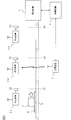
- FIG. 1 is a schematic diagram showing a configuration of a system including a wireless power transmission system according to the first embodiment.
- the wireless power transmission system of FIG. 1 includes a wireless power transmission device 1 and at least one wireless power receiving device 2-1 to 2-3, and wirelessly transmits power from the wireless power transmitting device 1 to the wireless power receiving devices 2-1 to 2-3. To do.
- wireless power receiving devices 2-1 to 2-3 are collectively referred to as “wireless power receiving device 2".
- FIG. 1 shows a case where the wireless power transmission system includes three wireless power receiving devices 2, the wireless power transmission system may include an arbitrary number of wireless power receiving devices 2.
- the wireless power transmission device 1 is referred to as a "power transmission device 1”
- the wireless power receiving device 2 is referred to as a "power receiving device 2”.
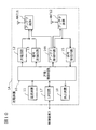
- FIG. 2 is a block diagram showing the configuration of the power transmission device 1 of FIG.
- the power transmission device 1 includes at least a power transmission control circuit 10, a power transmission circuit 12, a signal transmission circuit 13, and a signal reception circuit 15.
- the power transmission control circuit 10 is a control circuit of the power transmission device 1 that controls the overall operation of the power transmission device 1.
- the power transmission circuit 12 transmits power for operating the sensor 23 (described later) of the power receiving device 2 to the power receiving device 2.
- the signal transmission circuit 13 transmits a control signal for controlling the sensor 23 to the power receiving device 2.
- the signal receiving circuit 15 acquires an estimated value of the power receiving level indicating the level of the power transmitted from the power transmitting device 1 and received by the power receiving device 2.
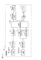
- FIG. 3 is a block diagram showing the configuration of the power receiving device 2 of FIG.
- the power receiving device 2 includes at least a power storage device 22 and a sensor 23.
- the power storage device 22 stores the electric power wirelessly transmitted from the power transmission device 1 to the power reception device 2.
- the power storage device 22 includes, for example, a rechargeable battery or a capacitor.
- the sensor 23 is a load device that operates by the electric power stored in the power storage device 22.
- the power transmission control circuit 10 waits for a predetermined standby time Tw, and then waits for a predetermined standby time Tw.
- the control signal for operating the sensor 23 is transmitted by the signal transmission circuit 13.
- the power storage device 22 When the power storage device 22 has a charging voltage higher than a predetermined threshold value Th2, the power storage device 22 can supply power to the sensor 23 so that the sensor 23 can operate stably.
- the power receiving level threshold Th1 may be set, for example, so that the charging voltage of the power storage device 22 reaches the threshold Th2 after a sufficiently long time has elapsed.
- the standby time Tw is, for example, the time from zero to the time when the charging voltage of the power storage device 22 reaches the threshold Th2 when the power receiving device 2 receives power at a standard power receiving level higher than the threshold Th1.
- the standby time Tw After waiting for a long time, a control signal for operating the sensor 23 is transmitted.
- the charging voltage of the power storage device 22 is considered to be equal to or higher than the threshold value Th2
- electric power can be wirelessly transmitted from the power transmitting device 1 to the power receiving device 2 so that the sensor 23 is less likely to malfunction due to insufficient power.
- the control signal for operating the sensor 23 may include, for example, turning on the sensor 23, measuring a predetermined physical quantity by the sensor 23, reading out the physical quantity measured by the sensor 23, and the like.
- the power transmission device 1 and the power receiving devices 2-1 to 2-3 are provided in a factory equipped with a control device 3, a manufacturing device 4, and a belt conveyor 5.
- the belt conveyor 5 conveys the pallet 6 and the work 7.
- the pallet 6 and the work 7 are moved by the belt conveyor 5 so as to arrive at the predetermined positions p1 to p3 at a predetermined time.
- predetermined work events are executed for the work 7.
- the power receiving devices 2-1 to 2-3 are provided in the vicinity of the positions p1 to p3, respectively, and are associated with the events executed at the positions p1 to p3, respectively.
- Sensors 23 of each of the power receiving devices 2-1 to 2-3 measure a predetermined physical quantity associated with this event.
- the power transmission device 1 collects the measured physical quantity from each of the power receiving devices 2-1 to 2-3 and sends it to the control device 3.
- the control device 3 controls the operation of the manufacturing device 4 based on the measured physical quantity.
- the control device 3 is, for example, a programmable logic controller.
- the manufacturing apparatus 4 executes an event of a predetermined work (for example, a processing process such as welding) on the work 7.
- the power transmission device 1 is connected to the control device 3 and the manufacturing device 4 as external devices.
- the power transmission device 1 includes a power transmission control circuit 10, a power supply device 11, a power transmission circuit 12, a signal transmission circuit 13, an antenna control circuit 14, a signal reception circuit 15, a circulator 16, an antenna device ANT1, and an interface (I /).
- the circuit 17 and the display device 18 are provided.
- the power transmission control circuit 10 controls the overall operation of the power transmission device 1.
- the power supply device 11 supplies the electric power transmitted to the power receiving device 2.
- the power transmission circuit 12 transmits the electric power for operating the sensor 23 of the power receiving device 2 to the power receiving device 2 via the circulator 16 and the antenna device ANT1.
- the power transmission circuit 12 generates a CW (continuous wave) wave from, for example, the electric power supplied by the power supply device 11.
- the signal transmission circuit 13 transmits a control signal for controlling the sensor 23 (for example, a read signal of the sensor 23) to the power receiving device 2 via the circulator 16 and the antenna device ANT1.
- the signal receiving circuit 15 receives, for example, a response signal including a physical quantity measured by the sensor 23 from the power receiving device 2 via the antenna device ANT1 and the circulator 16. Further, the signal receiving circuit 15 acquires an estimated value of the power receiving level as described above.
- the estimated value of the power receiving level may be generated by the power transmitting device 1 or may be generated by the power receiving device 2 and received from the power receiving device 2 via the antenna device ANT1 and the circulator 16 as described later.
- the antenna device ANT1 has a variable directivity.
- the antenna device ANT1 is, for example, an array antenna including a plurality of antenna elements, and its directivity changes by individually adjusting the amplitude and phase of the signals transmitted and received by each antenna element.
- the antenna control circuit 14 controls the directivity of the antenna device ANT1 under the control of the power transmission control circuit 10.
- the circulator 16 synthesizes and separates the power and the signal sent to the power receiving device 2 via the antenna device ANT1 and the signal received from the power receiving device 2 via the antenna device ANT1.
- the interface circuit 17 is connected to the control device 3 via a wired or wireless communication line.
- the power transmission control circuit 10 generates a state signal indicating whether or not the sensor 23 can operate, and outputs the state signal to the control device 3 via the interface circuit 17. Further, as will be described later, the power transmission control circuit 10 generates a read result signal including the physical quantity measured by the sensor 23, and transmits the read result signal to the control device 3 via the interface circuit 17.
- the display device 18 displays the status of the power transmission device 1 and the status (power reception level, etc.) of the power reception device 2 communicably connected to the power transmission device 1.
- the power receiving device 2 includes a power receiving control circuit 20, a power conversion circuit 21, a power storage device 22, a sensor 23, a matching circuit 24, a circulator 25, a signal transmitting circuit 26, a signal receiving circuit 27, a power receiving circuit 28, and an antenna.
- the device ANT2 and the switch SW are provided.
- the power receiving control circuit 20 controls the overall operation of the power receiving device 2.
- the antenna device ANT2 has a predetermined directivity or omnidirectionality.
- the matching circuit 24 matches the impedance of the antenna device ANT2 with the impedance of the circulator 25 and other circuits.
- the circulator 25 synthesizes and separates the electric power and the signal sent from the power transmission device 1 via the antenna device ANT2 and the signal sent to the power transmission device 1 via the antenna device ANT2.
- the signal transmission circuit 26 transmits, for example, a response signal including a physical quantity measured by the sensor 23 via the circulator 25, the matching circuit 24, and the antenna device ANT2.
- the signal receiving circuit 27 receives a control signal for controlling the sensor 23 from the power transmitting device 1 via the antenna device ANT2, the matching circuit 24, and the circulator 25.
- the power receiving circuit 28 receives electric power for operating the sensor 23 from the power transmitting device 1 via the antenna device ANT2, the matching circuit 24, and the circulator 25.
- the power conversion circuit 21 converts (rectifies) the power wirelessly transmitted from the power transmitting device 1 to the power receiving device 2 from alternating current to direct current, and further boosts or steps down the direct current power.
- the power storage device 22 stores the power that is wirelessly transmitted from the power transmission device 1 to the power reception device 2 and is boosted or stepped down by the power conversion circuit 21.
- the power storage device 22 includes, for example, a rechargeable battery or a capacitor.
- the sensor 23 operates by the electric power stored in the power storage device 22 and measures a predetermined physical quantity.
- the sensor 23 is connected to the power receiving control circuit 20 via a switch SW that turns on / off under the control of the power receiving control circuit 20. When the switch SW is on, power is supplied from the power storage device 22 to the sensor 23, and the physical quantity measured by the sensor 23 is sent to the power receiving control circuit 20. The physical quantity measured by the sensor 23 is wirelessly transmitted to the power transmission device 1.
- the signal transmitting circuit 26 of the power receiving device 2 may wirelessly transmit the test signal, and the signal receiving circuit 15 of the power transmitting device 1 wirelessly receives the test signal and receives the test signal.
- the strength may be measured.
- the signal receiving circuit 15 of the power transmission device 1 may measure the received signal strength of the test signal as it is, or may measure the received signal strength of the amplified test signal, and test instead of the received signal strength of the test signal. The power of the signal may be measured.
- the signal transmitting circuit 13 of the power transmitting device 1 may wirelessly transmit the test signal, and the signal receiving circuit 27 of the power receiving device 2 wirelessly receives the test signal and receives the test signal.
- the strength may be measured.
- the signal receiving circuit 27 of the power receiving device 2 may measure the received signal strength of the test signal as it is, or may measure the received signal strength of the amplified test signal, and test instead of the received signal strength of the test signal. The power of the signal may be measured.
- the signal transmitting circuit 13 of the power transmitting device 1 may wirelessly transmit the test signal, and the signal receiving circuit 15 of the power transmitting device 1 wirelessly receives the test signal reflected by the power receiving device 2. Then, the received signal strength of the test signal may be measured.
- the power receiving device 2 since the power receiving device 2 reflects the test signal transmitted from the power transmission device 1, for example, impedance mismatch occurs in any circuit portion selectively under the control of the power receiving control circuit 20. It may be configured in.
- the test signal may be a communication signal having a predetermined format, or may be a CW (continuous wave) wave. Further, the test signal may be transmitted in response to a command signal generated by the power transmitting device 1 or the power receiving device 2, or may be transmitted periodically without a command signal.
- the charging voltage of the power storage device 22 may be measured in order to estimate the power receiving level.
- the power supplied to the load device of the power receiving device 2 for example, the power conversion circuit 21, the power storage device 22, or the sensor 23 may be measured.
- the environment around the power transmitting device 1 and the power receiving device 2 is different between when the power transmitting device 1 and the power receiving device 2 of FIG. 1 are installed in the factory and when the factory is actually operated. For example, at the time of installation, the manufacturing device 4 and the belt conveyor 5 are stopped, while at the time of operation, the manufacturing device 4 and the belt conveyor 5 are operated, and the pallet 6 and the work 7 pass near the power transmission device 1 and the power receiving device 2. To do.
- the radio wave propagation environment changes. Therefore, at the time of installation, the main beam direction of the antenna device ANT1 of the power transmission device 1 is adjusted according to the position of each power receiving device 2, and the main beam direction of the antenna device ANT2 of each power receiving device 2 is set to the position of the power transmission device 1. Even if adjusted accordingly, the propagation path of radio waves may change or be blocked during operation. As a result, the power receiving level of any of the power receiving devices 2 becomes smaller than the threshold value Th1, and the sensor 23 cannot supply power that can be stably operated to the sensor 23. If the sensor 23 malfunctions due to insufficient power, the product processed by the manufacturing apparatus 4 may be defective or the manufacturing apparatus 4 may malfunction.
- the wireless power transmission system wirelessly transmits power from the power transmission device 1 to the power receiving device 2 so that malfunction of the sensor 23 due to power shortage is unlikely to occur.
- FIG. 4 is a timing chart showing changes in the charging voltage and the state signal when the power receiving level of the power receiving device 2 of FIG. 1 always exceeds the threshold value Th1.
- the power transmission control circuit 10 determines whether or not the sensor 23 can operate based on the power reception level, that is, whether or not the power storage device 22 can supply the sensor 23 with power that allows the sensor 23 to operate stably.
- a state signal indicating the above is generated.
- the state signal is always at a high level, indicating that the sensor 23 is always operational (enabled).
- the display device 18 may display at least one of the power receiving level, charging voltage, and status signal shown in FIG.
- FIG. 5 is a timing chart showing an example of changes in the charging voltage and the state signal when the power receiving level of the power receiving device 2 of FIG. 1 becomes smaller than the threshold value Th1.
- the manufacturing device 4 and the belt conveyor 5 operate, and the pallet 6 and the work 7 pass near the power transmitting device 1 and the power receiving device 2.
- the propagation of radio waves is periodically cut off between the power transmitting device 1 and the power receiving device 2, the power receiving level is periodically made smaller than the threshold Th1, and the charging voltage of the power storage device 22 is also periodically blocked at the threshold Th2. It becomes smaller.
- the power transmission control circuit 10 sets the state signal to a low level.
- the power transmission control circuit 10 waits for the standby time Thw and then outputs the state signal from the low level. Transition to high level.
- FIG. 6 is a timing chart showing another example of changes in the charging voltage and the state signal when the power receiving level of the power receiving device 2 of FIG. 1 becomes smaller than the threshold value Th1.
- the sensor 23 is operational (enabled) when the status signal is high level, and the sensor 23 is inoperable (disabled) when the status signal is low level. Is shown.
- the state signal when the state signal is low level, it indicates that the sensor 23 is operable (enabled), and when the state signal is high level, the sensor 23 is inoperable (disabled). It may be shown that.
- Each power receiving device 2 is periodically assigned a plurality of time slots for wirelessly transmitting electric power from the power transmitting device 1 to each power receiving device 2.
- the control signal for controlling the sensor 23 and the measured physical quantity are transmitted and received in a time-division manner.
- FIGS. 4 to 6 and others for simplification of illustration, only wireless transmission of electric power is shown, and transmission / reception of other signals is omitted.
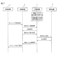
- FIG. 7 is a sequence diagram showing an example of the operation of the system of FIG.
- the power transmission device 1 acquires an estimated value of the power reception level of each power reception device 2 in advance, and sets a status signal of each power reception device 2 based on the power reception level.
- the manufacturing device 4 transmits a sensing request signal to the control device 3 in order to operate the sensor 23 of each power receiving device 2.
- the control device 3 transmits a read start signal to the power transmission device 1 in order to start reading the measured value of the sensor 23.
- the power transmission device 1 then transmits a status signal to the control device 3.
- the control device 3 When the sensor 23 is inoperable (disabled), the control device 3 repeatedly transmits a read start signal to the power transmission device 1 until the sensor 23 becomes operable (enabled).
- the control device 3 transmits a read request signal to the power transmission device 1 in order to request the reading of the measured value of the sensor 23 by the power transmission device 1.
- the power transmission device 1 transmits a read signal to the power receiving device 2 in order to read the measured value of the sensor 23.
- the power receiving device 2 transmits a response signal including the physical quantity measured by the sensor 23 to the power transmitting device 1.
- the power transmission device 1 transmits a read result signal including the physical quantity measured by the sensor 23 to the control device 3.
- control device 3 determines whether or not the physical quantity measured by the sensor 23 meets a predetermined standard (for example, a standard indicating that the manufacturing device 4 may operate), and includes the result.
- the sensing completion signal is transmitted to the manufacturing apparatus 4. After that, the control device 3 transmits a control signal for controlling the manufacturing device 4 to the manufacturing device 4.
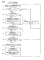
- FIG. 8 is a flowchart showing a sensing process executed by the power transmission control circuit 10 of the power transmission device 1 of FIG.
- step S1 the power transmission control circuit 10 acquires an estimated value of the power reception level of each power receiving device 2 by using the signal receiving circuit 15.
- step S2 the power transmission control circuit 10 determines whether or not the power receiving level is equal to or higher than the threshold value Th1, and if YES, proceeds to step S3, and if NO, proceeds to step S12.
- step S3 the power transmission control circuit 10 determines whether or not the state signal is disabled, and if YES, proceeds to step S4, and if NO, proceeds to step S6.
- step S3 the power transmission control circuit 10 waits for the standby period Tw while the state signal is disabled in step S4, and shifts the state signal from disabled to enabled in step S5.
- step S3 is NO, the power transmission control circuit 10 keeps the status signal enabled.
- step S6 the power transmission control circuit 10 determines whether or not the read start signal has been received from the control device 3, and if YES, proceeds to step S7, and if NO, proceeds to step S8.
- step S7 the power transmission control circuit 10 transmits a status signal to the control device 3.
- step S8 the power transmission control circuit 10 determines whether or not a read request signal has been received from the control device 3, and if YES, proceeds to step S9, and if NO, returns to step S1.
- step S9 the power transmission control circuit 10 transmits a read signal to the power receiving device 2.
- the power receiving control circuit 20 receives the read signal, it acquires the physical quantity measured by the sensor 23.
- step S10 the power transmission control circuit 10 receives the response signal including the physical quantity measured by the sensor 23 from the power receiving device 2.
- step S11 the power transmission control circuit 10 transmits a read result signal including the physical quantity measured by the sensor 23 to the control device 3.
- step S2 When step S2 is NO, the power transmission control circuit 10 sets the status signal to disabled in step S12.
- power is transmitted from the power transmission device 1 to the power receiving device 2 so that the sensor 23 is less likely to malfunction due to power shortage by executing the processes of FIGS. 7 and 8. Can be transmitted wirelessly.
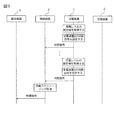
- FIG. 9 is a sequence diagram showing a modified example of the operation of the system of FIG. As the system of FIG. 1 repeats the operation of FIG. 7, the control device 3 collects a state signal indicating whether or not the sensor 23 of each power receiving device 2 is operable. In FIG. 9, for the sake of simplification of the illustration, the operations related to the generation and transmission of the state signal are omitted from each operation of FIG. 7.
- the control device 3 collects the status signals of each power receiving device 2 over a predetermined time length
- the control device 3 performs an automatic scheduling process for automatically determining a schedule for operating the manufacturing device 4 based on the collected status signals. Execute.
- the control device 3 extracts the time period during which the sensor 23 can operate and the time period during which the sensor 23 cannot operate from the collected state signals, and manufactures the sensor 23 during the time period during which the sensor 23 can operate.
- the schedule for operating the manufacturing apparatus 4 is determined so that the apparatus 4 is operated.
- FIG. 10 is a schematic view showing a configuration of a power transmission device 1A of a wireless power transmission system according to a modified example of the first embodiment.
- the power transmission device 1A includes antenna devices ANT11, ANT12 and an antenna control circuit 14A in place of the antenna device ANT1, the antenna control circuit 14, and the circulator 16 in FIG. Instead of sharing one antenna device ANT1 for transmission and reception, separate antenna devices ANT11 and ANT12 may be used.
- the antenna control circuit 14A controls the directivity of the antenna devices ANT11 and ANT12 under the control of the power transmission control circuit 10.
- FIG. 11 is a schematic view showing the configuration of the power receiving device 2A of the wireless power transmission system according to the modified example of the first embodiment.
- the power receiving device 2A includes antenna devices ANT21, ANT22, a power receiving control circuit 20A, and matching circuits 24a and 24b in place of the antenna device ANT2, the power receiving control circuit 20, and the matching circuit 24 of FIG.
- antenna devices ANT21 and ANT22 may be used instead of sharing one antenna device ANT2 for transmission and reception.
- the wireless power transmission system can be applied to a radio wave propagation environment in which a periodic decrease in power reception level occurs, and also in a radio wave propagation environment in which an aperiodic decrease in power reception level occurs. Applicable.
- the senor 23 is less likely to malfunction, so that the product processed by the manufacturing apparatus 4 is less likely to be defective, and the manufacturing apparatus 4 is less likely to fail. Become.
- the control device 3 since the control device 3 recognizes whether or not the sensor 23 of each power receiving device 2 can operate, the control device 3 includes the manufacturing device 4 and the manufacturing device 4. While monitoring the environment around the belt conveyor 5, the manufacturing apparatus 4 can be operated during the time period during which the sensor 23 can be operated. As a result, defects of the product processed by the manufacturing apparatus 4 are less likely to occur, and failures of the manufacturing apparatus 4 are less likely to occur.
- the wireless power transmission system by visualizing the state (power receiving level, etc.) of the power receiving device 2 by using the display device 18, for example, the designer of the manufacturing line of the factory can receive each power.
- the operation timing of the manufacturing apparatus 4 and the belt conveyor 5 can be appropriately determined according to whether or not the sensor 23 of the apparatus 2 is operable (that is, a change in the radio wave propagation environment).
- the wireless power transmission system according to the second embodiment is configured in the same manner as the wireless power transmission system according to the first embodiment. Therefore, a repetitive description of the configuration will be omitted.
- the power transmission control circuit 10 periodically allocates a plurality of time slots for wirelessly transmitting electric power from the power transmission device 1 to each power receiving device 2 to each power receiving device 2.
- the power transmission control circuit 10 is assigned to the same power receiving device 2 and is assigned to the first time slot. Extend a second time slot that precedes or follows.
- the wireless power transmission system according to the second embodiment, the other time slot assigned to the same power receiving device 2 is extended in order to compensate for the decrease in the charging voltage. As a result, electric power can be wirelessly transmitted from the power transmitting device 1 to the power receiving device 2 so that the sensor 23 is less likely to malfunction due to insufficient power.
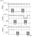
- FIG. 12 is a timing chart showing the initial state of the time slots assigned to the power receiving devices 2-1 to 2-3 of the wireless power transmission system according to the second embodiment.
- time slots T1 (1) and T1 (2) are assigned to the power receiving device 2-1 and time slots T2 (1) and T2 (2) are assigned to the power receiving device 2-2.
- Time slots T3 (1) and T3 (2) are assigned to 2-3.
- the power receiving level of the power receiving device 2-2 is smaller than the threshold value Th1 in the time interval including the time slot T2 (2) assigned to the power receiving device 2-2.
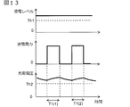
- FIG. 13 is a timing chart showing changes in the transmitted power and the charging voltage related to the power receiving device 2-1 when the power receiving level of the power receiving device 2-1 in FIG. 12 always exceeds the threshold value Th1. In the example of FIG. 13, the charging voltage always exceeds the threshold Th2.
- FIG. 14 relates to the power receiving device 2-2 when the power receiving level of the power receiving device 2-2 of FIG. 12 is smaller than the threshold value Th1 in the time slot T2 (2) but the length of each time slot is not changed. It is a timing chart which shows the change of transmission power and charge voltage.
- the power receiving level in the time slot T2 (2) (referred to as “first time slot”) assigned to the power receiving device 2-2, the power receiving level becomes smaller than the threshold Th1, so that the charging voltage becomes threshold. It is smaller than the value Th2. As a result, the sensor 23 may malfunction.
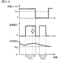
- FIG. 15 shows the power receiving device 2-2 when the power receiving level of the power receiving device 2-2 of FIG. 12 becomes smaller than the threshold value Th1 in the time slot T2 (2) and the preceding time slot T2 (1) is extended. It is a timing chart which shows the change of the transmission power and the charge voltage which concerns on.
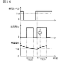
- FIG. 16 shows the power receiving device 2-2 when the power receiving level of the power receiving device 2-2 of FIG. 12 becomes smaller than the threshold value Th1 in the time slot T2 (2) and the subsequent time slot T2 (3) is extended. It is a timing chart which shows the change of the transmission power and the charge voltage which concerns on.
- the power transmission device 1 When the power receiving level of a certain power receiving device 2 drops periodically, the power transmission device 1 is prevented from malfunctioning due to a power shortage by extending another time slot assigned to the same power receiving device 2. Can wirelessly transmit power to the power receiving device 2.
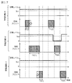
- FIG. 17 shows the length of the time slot assigned to the power receiving devices 2-1 to 2-3 when the power receiving level of the power receiving device 2-2 of FIG. 12 is smaller than the threshold value Th1 in the time slot T2 (2). It is a timing chart showing the change of.
- the power transmission control circuit 10 is assigned to another power receiving device 2-1 or 2-3 different from the power receiving device 2-2 to which the time slots T2 (1) to T2 (2) are assigned, and the time slot T2 (1) Time slots T1 (1) and T3 (1) (referred to as "third time slots") adjacent to the time slots are shortened.
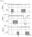
- FIG. 18 shows the length of the time slot assigned to the power receiving devices 2-1 to 2-3 when the power receiving level of the power receiving device 2-2 of FIG. 12 is smaller than the threshold value Th1 in the time slot T2 (2). It is a timing chart which shows the modification of the change of.
- the power transmission control circuit 10 is assigned to the same power receiving devices 2-1 and 2-3 to which the time slots T1 (1) and T3 (1) are assigned, and the time adjacent to the time slot T2 (2) in time. Slots T1 (2) and T3 (2) (referred to as "fourth time slot") are extended.
- power transmission from the power transmitting device 1 to the power receiving device 2-2 may be stopped in the time slot T2 (2).
- power is wirelessly transmitted from the power transmission device 1 to the power receiving device 2 so that the wireless resources for the plurality of power receiving devices 2 are effectively used and the sensor 23 is less likely to malfunction due to power shortage. Can be transmitted.
- the power transmission device 1 is prevented from malfunctioning due to power shortage by changing the length of the time slot assigned to each power receiving device 2. Can wirelessly transmit power to the power receiving device 2.
- the feature according to the first embodiment and the feature according to the second embodiment may be combined. That is, when the power receiving level becomes smaller than the predetermined threshold value Th1 in the first time slot assigned to a certain power receiving device 2, the power transmission control circuit 10 is assigned to the same power receiving device 2 and is assigned to the first power receiving device 2. When the second time slot preceding or following the time slot is extended and the power receiving level transitions from a state in which the power receiving level is smaller than the predetermined threshold value Th1 to a state in which the power receiving level is equal to or higher than the threshold value Th1 in advance. After waiting for a predetermined standby time Tw, the control signal for operating the sensor 23 may be transmitted by the signal transmission circuit 13. As a result, electric power can be wirelessly transmitted from the power transmitting device 1 to the power receiving device 2 so that the sensor 23 is less likely to malfunction due to insufficient power.
- the antenna device ANT2 of the power receiving device 2 may also have a variable directivity.
- the display device may be provided in another device, for example, a control device 3 instead of the power transmission device 1.
- the power receiving device 2 and the like may be provided with any other load device in place of the sensor 23 or in addition to the sensor 23.
- the other load device may be, for example, a lighting device, a switch or a relay that controls the other device, or a signal processing circuit that outputs a signal to the other device.
- the power receiving device may control another load device by using the detection result of the sensor 23 as a trigger.
- the wireless power transmission device 1 includes a power transmission circuit 12 that transmits electric power for operating the load device to the wireless power reception device 2, a signal transmission circuit 13 that transmits a control signal for controlling the load device to the wireless power reception device 2, and wireless power transmission. It includes a signal receiving circuit 15 that acquires an estimated value of the power receiving level indicating the level of power transmitted from the device 1 and received by the wireless power receiving device 2, and a power transmission control circuit 10 that controls the operation of the wireless power transmission device 1.
- the power transmission control circuit 10 periodically allocates a plurality of time slots for wirelessly transmitting electric power from the wireless power transmission device 1 to each wireless power receiving device 2 to each wireless power receiving device 2. Further, the power transmission control circuit 10 is assigned to the same wireless power receiving device 2 when the power receiving level becomes smaller than a predetermined threshold value in the first time slot assigned to the wireless power receiving device 2, and the first. Extend a second time slot that precedes or follows the time slot of.
- the wireless power transmission device 1 when the wireless power transmission device 1 according to the first aspect wirelessly transmits power from the wireless power transmission device 1 to a plurality of wireless power receiving devices 2, transmission control is performed.
- the circuit 10 is assigned to another wireless power receiving device 2 different from the wireless power receiving device 2 to which the first and second time slots are assigned, and has a third time slot that is temporally adjacent to the second time slot. Shorten.
- the transmission control circuit 10 is the same as the wireless power reception device 2 to which the third time slot is assigned.
- the fourth time slot which is assigned to the wireless power receiving device 2 and is temporally adjacent to the first time slot, is extended.
- the power transmission control circuit 10 has a predetermined power receiving level.
- the control signal is transmitted by the signal transmission circuit 13 after waiting for a predetermined standby time.
- the wireless power transmission device 1 in the wireless power transmission device 1 according to the fourth aspect, whether or not the power transmission control circuit 10 can operate the load device based on the power reception level. Generates a status signal indicating that. Further, the wireless power transmission device 1 further includes an interface circuit 17 that outputs a status signal to an external device.
- the wireless power transmission device wirelessly transmits power to at least one wireless power receiving device 2 including a load device that operates with the power of the power storage device 22.
- the wireless power transmission device 1 includes a power transmission circuit 12 that transmits electric power for operating the load device to the wireless power reception device 2, a signal transmission circuit 13 that transmits a control signal for controlling the load device to the wireless power reception device 2, and wireless power transmission. It includes a signal receiving circuit 15 that acquires an estimated value of the power receiving level indicating the level of power transmitted from the device 1 and received by the wireless power receiving device 2, and a power transmission control circuit 10 that controls the operation of the wireless power transmission device 1.
- the power transmission control circuit 10 transitions from a state in which the power receiving level is smaller than a predetermined threshold value to a state in which the power receiving level is equal to or higher than the threshold value, the power transmission control circuit 10 waits for a predetermined standby time and then loads.
- the control signal for operating the device is transmitted by the signal transmission circuit 13.
- the wireless power transmission device 1 in the wireless power transmission device 1 according to the sixth aspect, whether or not the load device can be operated by the power transmission control circuit 10 based on the power reception level. Generates a status signal indicating that. Further, the wireless power transmission device 1 further includes an interface circuit 17 that outputs a status signal to an external device.
- the wireless power transmission device 1 according to one aspect of the first to seventh aspects and a load device operated by the electric power of the power storage device 22 are provided. It is provided with one wireless power receiving device 2.
- the wireless power receiving device 2 includes a sensor 23 for measuring a predetermined physical quantity, and the sensor 23.
- the physical quantity measured by is wirelessly transmitted to the wireless power transmission device 1.
- the wireless power transmission system can be used to supply power to each sensor in a sensor network including, for example, a plurality of sensors.
- Wireless power transmission device power transmission device 2,2A, 2-1 to 2-3 Wireless power receiving device (power receiving device) 3
- Control device 4 Manufacturing device 5 Belt conveyor 6 Pallet 7 Work 10 Transmission control circuit 11 Power supply device 12 Transmission circuit 13 Signal transmission circuit 14, 14A Antenna control circuit 15 Signal reception circuit 16 Circulator 17 Interface (I / F) circuit 18 Display device 20, 20A Power receiving control circuit 21 Power conversion circuit 22 Power storage device 23 Sensor 24 Matching circuit 25 Circulator 26 Signal transmitting circuit 27 Signal receiving circuit 28 Power receiving circuit ANT1, ANT2, ANT2A, ANT11 to ANT22 Antenna device SW switch
Landscapes
- Engineering & Computer Science (AREA)
- Power Engineering (AREA)
- Computer Networks & Wireless Communication (AREA)
- Charge And Discharge Circuits For Batteries Or The Like (AREA)
- Transmitters (AREA)
Abstract
Description
蓄電デバイスの電力で動作する負荷装置を備えた少なくとも1つの無線受電装置に電力を無線伝送する無線送電装置であって、
前記無線送電装置は、
前記負荷装置を動作させるための電力を前記無線受電装置に送電する送電回路と、
前記負荷装置を制御する制御信号を前記無線受電装置に送信する信号送信回路と、
前記無線送電装置から送電されて前記無線受電装置によって受電される電力のレベルを示す受電レベルの推定値を取得する信号受信回路と、
前記無線送電装置の動作を制御する制御回路とを備え、
前記制御回路は、
前記無線送電装置から前記各無線受電装置に電力を無線伝送する複数の時間スロットを前記各無線受電装置に周期的に割り当て、
ある無線受電装置に割り当てられた第1の時間スロットにおいて前記受電レベルが予め決められたしきい値より小さくなったとき、同じ無線受電装置に割り当てられ、前記第1の時間スロットに先行又は後続する第2の時間スロットを延長する。
蓄電デバイスの電力で動作する負荷装置を備えた少なくとも1つの無線受電装置に電力を無線伝送する無線送電装置であって、
前記無線送電装置は、
前記負荷装置を動作させるための電力を前記無線受電装置に送電する送電回路と、
前記負荷装置を制御する制御信号を前記無線受電装置に送信する信号送信回路と、
前記無線送電装置から送電されて前記無線受電装置によって受電される電力のレベルを示す受電レベルの推定値を取得する信号受信回路と、
前記無線送電装置の動作を制御する制御回路とを備え、
前記制御回路は、前記受電レベルが予め決められたしきい値より小さい状態から前記受電レベルが前記しきい値以上である状態に遷移したとき、予め決められた待機時間だけ待機してから、前記負荷装置を動作させる制御信号を前記信号送信回路により送信する。
前記無線送電装置と、
蓄電デバイスの電力で動作する負荷装置を備えた少なくとも1つの無線受電装置とを備える。
図1~図11を参照して、第1の実施形態に係る無線電力伝送システムについて説明する。
図1は、第1の実施形態に係る無線電力伝送システムを含むシステムの構成を示す概略図である。図1の無線電力伝送システムは、無線送電装置1及び少なくとも1つの無線受電装置2-1~2-3を含み、無線送電装置1から無線受電装置2-1~2-3に電力を無線伝送する。
図1の例では、送電装置1及び受電装置2-1~2-3は、制御装置3、製造装置4、及びベルトコンベア5を備えた工場に設けられる。ベルトコンベア5は、パレット6及びワーク7を搬送する。パレット6及びワーク7は、ベルトコンベア5によって、予め決められた時間において予め決められた位置p1~p3に到着しているように移動される。位置p1~p3において、ワーク7に対して予め決められた作業のイベントがそれぞれ実行される。受電装置2-1~2-3は、位置p1~p3の近傍にそれぞれ設けられ、位置p1~p3において実行されるイベントにそれぞれ関連付けられる。各受電装置2-1~2-3のセンサ23は、このイベントに関連付けられた予め決められた物理量を測定する。送電装置1は、測定された物理量を各受電装置2-1~2-3から収集し、制御装置3に送る。制御装置3は、測定された物理量に基づいて製造装置4の動作を制御する。制御装置3は、例えば、プログラマブルロジックコントローラである。製造装置4は、ワーク7に対して予め決められた作業(例えば、溶接などの加工工程)のイベントを実行する。
図1の送電装置1及び受電装置2を工場に設置するときと、工場を実際に稼働させているときとでは、送電装置1及び受電装置2の周囲の環境がさまざまに異なる。例えば、設置時には、製造装置4及びベルトコンベア5が停止している一方、稼働時には、製造装置4及びベルトコンベア5が動作し、送電装置1及び受電装置2の近くをパレット6及びワーク7が通過する。
(1)受電レベルの推定(すなわち、テスト信号の送受信)と、
(2)電力の無線伝送と、
(3)センサ23を制御する制御信号及び測定された物理量の送受信と
が時分割で行われる。図4~図6他では、図示の簡単化のために、電力の無線伝送のみを示し、他の信号の送受信を省略している。
図10は、第1の実施形態の変形例に係る無線電力伝送システムの送電装置1Aの構成を示す概略図である。送電装置1Aは、図2のアンテナ装置ANT1、アンテナ制御回路14、及びサーキュレータ16に代えて、アンテナ装置ANT11,ANT12及びアンテナ制御回路14Aを備える。送信及び受信のために1つのアンテナ装置ANT1を共用するのではなく、別個のアンテナ装置ANT11,ANT12を用いてもよい。アンテナ制御回路14Aは、送電制御回路10の制御下で、アンテナ装置ANT11,ANT12の指向性を制御する。
第1の実施形態に係る無線電力伝送システムによれば、受電レベルがしきい値Th1より小さい状態から受電レベルがしきい値Th1以上である状態に遷移したとき、待機時間Twだけ待機してから、センサ23を動作させる制御信号を送信する。このとき、蓄電デバイス22の充電電圧はしきい値Th2以上であると考えられるので、センサ23が安定して動作可能な電力をセンサ23に供給することができる。これにより、電力不足によるセンサ23の誤動作が生じにくいように、送電装置1から受電装置2に電力を無線伝送することができる。
図12~図18を参照して、第2の実施形態に係る無線電力伝送システムについて説明する。
第2の実施形態に係る無線電力伝送システムは、第1の実施形態に係る無線電力伝送システムと同様に構成される。従って、その構成についての繰り返しの説明は省略する。
図12は、第2の実施形態に係る無線電力伝送システムの受電装置2-1~2-3に割り当てられる時間スロットの初期状態を示すタイミングチャートである。図12の例では、受電装置2-1に時間スロットT1(1),T1(2)が割り当てられ、受電装置2-2に時間スロットT2(1),T2(2)が割り当てられ、受電装置2-3に時間スロットT3(1),T3(2)が割り当てられる。図12の例では、受電装置2-2に割り当てられた時間スロットT2(2)を含む時間区間において、受電装置2-2の受電レベルがしきい値Th1よりも小さくなっている。
第2の実施形態に係る無線電力伝送システムによれば、各受電装置2に割り当てられた時間スロットの長さを変更することにより、電力不足によるセンサ23の誤動作が生じにくいように、送電装置1から受電装置2に電力を無線伝送することができる。
受電装置2のアンテナ装置ANT2もまた、可変な指向性を有してもよい。
本開示の各側面に係る無線送電装置及び無線電力伝送システムは、以下のように表現されてもよい。
2,2A,2-1~2-3 無線受電装置(受電装置)
3 制御装置
4 製造装置
5 ベルトコンベア
6 パレット
7 ワーク
10 送電制御回路
11 電源装置
12 送電回路
13 信号送信回路
14,14A アンテナ制御回路
15 信号受信回路
16 サーキュレータ
17 インターフェース(I/F)回路
18 表示装置
20,20A 受電制御回路
21 電力変換回路
22 蓄電デバイス
23 センサ
24 整合回路
25 サーキュレータ
26 信号送信回路
27 信号受信回路
28 受電回路
ANT1,ANT2,ANT2A,ANT11~ANT22 アンテナ装置
SW スイッチ
Claims (9)
- 蓄電デバイスの電力で動作する負荷装置を備えた少なくとも1つの無線受電装置に電力を無線伝送する無線送電装置であって、
前記無線送電装置は、
前記負荷装置を動作させるための電力を前記無線受電装置に送電する送電回路と、
前記負荷装置を制御する制御信号を前記無線受電装置に送信する信号送信回路と、
前記無線送電装置から送電されて前記無線受電装置によって受電される電力のレベルを示す受電レベルの推定値を取得する信号受信回路と、
前記無線送電装置の動作を制御する制御回路とを備え、
前記制御回路は、
前記無線送電装置から前記各無線受電装置に電力を無線伝送する複数の時間スロットを前記各無線受電装置に周期的に割り当て、
ある無線受電装置に割り当てられた第1の時間スロットにおいて前記受電レベルが予め決められたしきい値より小さくなったとき、同じ無線受電装置に割り当てられ、前記第1の時間スロットに先行又は後続する第2の時間スロットを延長する、
無線送電装置。 - 前記無線送電装置から複数の無線受電装置に電力を無線伝送するとき、前記制御回路は、前記第1及び第2の時間スロットが割り当てられた無線受電装置とは異なる他の無線受電装置に割り当てられ、前記第2の時間スロットに時間的に隣接する第3の時間スロットを短縮する、
請求項1記載の無線送電装置。 - 前記制御回路は、前記第3の時間スロットが割り当てられた無線受電装置と同じ無線受電装置に割り当てられ、前記第1の時間スロットに時間的に隣接する第4の時間スロットを延長する、
請求項2記載の無線送電装置。 - 前記制御回路は、前記受電レベルが予め決められたしきい値より小さい状態から前記受電レベルが前記しきい値以上である状態に遷移したとき、予め決められた待機時間だけ待機してから前記信号送信回路により前記制御信号を送信する、
請求項1~3のうちの1つに記載の無線送電装置。 - 前記制御回路は、前記受電レベルに基づいて、前記負荷装置が動作可能であるか否かを示す状態信号を生成し、
前記無線送電装置は、前記状態信号を外部装置に出力するインターフェース回路をさらに備えた、
請求項4記載の無線送電装置。 - 蓄電デバイスの電力で動作する負荷装置を備えた少なくとも1つの無線受電装置に電力を無線伝送する無線送電装置であって、
前記無線送電装置は、
前記負荷装置を動作させるための電力を前記無線受電装置に送電する送電回路と、
前記負荷装置を制御する制御信号を前記無線受電装置に送信する信号送信回路と、
前記無線送電装置から送電されて前記無線受電装置によって受電される電力のレベルを示す受電レベルの推定値を取得する信号受信回路と、
前記無線送電装置の動作を制御する制御回路とを備え、
前記制御回路は、前記受電レベルが予め決められたしきい値より小さい状態から前記受電レベルが前記しきい値以上である状態に遷移したとき、予め決められた待機時間だけ待機してから、前記負荷装置を動作させる制御信号を前記信号送信回路により送信する、
無線送電装置。 - 前記制御回路は、前記受電レベルに基づいて、前記負荷装置が動作可能であるか否かを示す状態信号を生成し、
前記無線送電装置は、前記状態信号を外部装置に出力するインターフェース回路をさらに備えた、
請求項6記載の無線送電装置。 - 請求項1~7のうちの1つに記載の無線送電装置と、
蓄電デバイスの電力で動作する負荷装置を備えた少なくとも1つの無線受電装置とを備えた、
無線電力伝送システム。 - 前記無線受電装置は、予め決められた物理量を測定するセンサを備え、前記センサによって測定された物理量を前記無線送電装置に無線送信する、
請求項8記載の無線電力伝送システム。
Priority Applications (5)
| Application Number | Priority Date | Filing Date | Title |
|---|---|---|---|
| US17/629,929 US11979035B2 (en) | 2019-08-19 | 2019-08-19 | Wireless power transmission system for wirelessly transmitting power to prevent power shortage in load device of wireless power receiving apparatus |
| JP2021541358A JP7259970B2 (ja) | 2019-08-19 | 2019-08-19 | 無線電力伝送システム |
| CN201980098872.7A CN114175453B (zh) | 2019-08-19 | 2019-08-19 | 无线电力传输系统 |
| EP19942087.8A EP4020760B1 (en) | 2019-08-19 | 2019-08-19 | Wireless power transmission system |
| PCT/JP2019/032283 WO2021033236A1 (ja) | 2019-08-19 | 2019-08-19 | 無線電力伝送システム |
Applications Claiming Priority (1)
| Application Number | Priority Date | Filing Date | Title |
|---|---|---|---|
| PCT/JP2019/032283 WO2021033236A1 (ja) | 2019-08-19 | 2019-08-19 | 無線電力伝送システム |
Publications (1)
| Publication Number | Publication Date |
|---|---|
| WO2021033236A1 true WO2021033236A1 (ja) | 2021-02-25 |
Family
ID=74659680
Family Applications (1)
| Application Number | Title | Priority Date | Filing Date |
|---|---|---|---|
| PCT/JP2019/032283 Ceased WO2021033236A1 (ja) | 2019-08-19 | 2019-08-19 | 無線電力伝送システム |
Country Status (5)
| Country | Link |
|---|---|
| US (1) | US11979035B2 (ja) |
| EP (1) | EP4020760B1 (ja) |
| JP (1) | JP7259970B2 (ja) |
| CN (1) | CN114175453B (ja) |
| WO (1) | WO2021033236A1 (ja) |
Cited By (5)
| Publication number | Priority date | Publication date | Assignee | Title |
|---|---|---|---|---|
| JP2023028926A (ja) * | 2021-08-20 | 2023-03-03 | テイ・エス テック株式会社 | 給電システム及び車両用シート |
| JP2023131362A (ja) * | 2022-03-09 | 2023-09-22 | 豊田合成株式会社 | 無線給電システム |
| JP7446027B1 (ja) | 2023-05-23 | 2024-03-08 | エイターリンク株式会社 | 受信機、プログラム、方法及び無線給電システム |
| JP7507518B1 (ja) | 2023-05-23 | 2024-06-28 | エイターリンク株式会社 | 受信機、方法、電子回路、及び無線給電システム |
| JP7531244B1 (ja) | 2023-03-17 | 2024-08-09 | エイターリンク株式会社 | プログラム、方法、受信機、無線給電システム及び送信機 |
Families Citing this family (2)
| Publication number | Priority date | Publication date | Assignee | Title |
|---|---|---|---|---|
| JPWO2020137815A1 (ja) * | 2018-12-25 | 2021-11-04 | 三洋電機株式会社 | 待機用電源装置及び二次電池の充電方法 |
| WO2021014496A1 (ja) * | 2019-07-19 | 2021-01-28 | オムロン株式会社 | 給電装置および給電システム |
Citations (3)
| Publication number | Priority date | Publication date | Assignee | Title |
|---|---|---|---|---|
| JP2009268311A (ja) * | 2008-04-28 | 2009-11-12 | Sony Corp | 送電装置、送電方法、プログラム、および電力伝送システム |
| JP2014505460A (ja) * | 2011-02-07 | 2014-02-27 | サムスン エレクトロニクス カンパニー リミテッド | 無線電力送受信制御方法及び装置、並びに無線電力伝送システム |
| JP2018102087A (ja) | 2016-12-21 | 2018-06-28 | Kddi株式会社 | 送電装置及び送電出力制御方法 |
Family Cites Families (16)
| Publication number | Priority date | Publication date | Assignee | Title |
|---|---|---|---|---|
| JP4600464B2 (ja) * | 2007-11-22 | 2010-12-15 | セイコーエプソン株式会社 | 送電制御装置、送電装置、電子機器及び無接点電力伝送システム |
| KR101730406B1 (ko) * | 2010-09-15 | 2017-04-26 | 삼성전자주식회사 | 무선 전력 전송 및 수신 장치 |
| KR101813129B1 (ko) * | 2011-05-04 | 2017-12-28 | 삼성전자주식회사 | 무선 전력 송수신 시스템 |
| KR20120125180A (ko) * | 2011-05-06 | 2012-11-14 | 주식회사 엘씨링크 | 무선 전력 전송에서 충돌 회피 장치 및 방법 |
| JP5649603B2 (ja) * | 2012-03-21 | 2015-01-07 | 株式会社東芝 | 送電装置および送電方法 |
| KR20130128514A (ko) * | 2012-05-17 | 2013-11-27 | 엘에스전선 주식회사 | 시분할 무선 전력 전송 방법 및 무선 전력 전송 장치 |
| JP6200167B2 (ja) * | 2013-02-27 | 2017-09-20 | デクセリアルズ株式会社 | 受電装置、受電電力調整方法、受電電力調整プログラム、及び半導体装置 |
| WO2014148369A1 (ja) * | 2013-03-19 | 2014-09-25 | 株式会社村田製作所 | ワイヤレス電力伝送システム |
| KR101776451B1 (ko) * | 2013-04-19 | 2017-09-07 | 캐논 가부시끼가이샤 | 송전 장치, 수전 장치, 이들의 제어 방법, 및 컴퓨터 판독가능 저장 매체 |
| JP6195351B2 (ja) * | 2013-05-14 | 2017-09-13 | キヤノン株式会社 | 送電装置、送電方法及びプログラム |
| CN105393432B (zh) * | 2013-07-31 | 2018-12-28 | 松下电器产业株式会社 | 无线电力传输系统以及送电装置 |
| JP6242311B2 (ja) * | 2013-10-29 | 2017-12-06 | パナソニック株式会社 | 無線送電装置及び無線電力伝送システム |
| JP6337797B2 (ja) * | 2015-02-13 | 2018-06-06 | オムロン株式会社 | 無線給電制御システム、無線給電制御装置、無線給電制御方法、及び指向性情報生成方法 |
| JP2018133922A (ja) * | 2017-02-15 | 2018-08-23 | キヤノン株式会社 | 充電制御装置およびその制御方法、並びにプログラム |
| WO2018190578A1 (en) * | 2017-04-12 | 2018-10-18 | Samsung Electronics Co., Ltd. | Wireless power transmitter, wireless power receiving electronic device, and method for operating the same |
| WO2020049853A1 (ja) * | 2018-09-05 | 2020-03-12 | 三菱電機株式会社 | 非接触給電システムおよび送電装置 |
-
2019
- 2019-08-19 CN CN201980098872.7A patent/CN114175453B/zh active Active
- 2019-08-19 WO PCT/JP2019/032283 patent/WO2021033236A1/ja not_active Ceased
- 2019-08-19 EP EP19942087.8A patent/EP4020760B1/en active Active
- 2019-08-19 US US17/629,929 patent/US11979035B2/en active Active
- 2019-08-19 JP JP2021541358A patent/JP7259970B2/ja active Active
Patent Citations (3)
| Publication number | Priority date | Publication date | Assignee | Title |
|---|---|---|---|---|
| JP2009268311A (ja) * | 2008-04-28 | 2009-11-12 | Sony Corp | 送電装置、送電方法、プログラム、および電力伝送システム |
| JP2014505460A (ja) * | 2011-02-07 | 2014-02-27 | サムスン エレクトロニクス カンパニー リミテッド | 無線電力送受信制御方法及び装置、並びに無線電力伝送システム |
| JP2018102087A (ja) | 2016-12-21 | 2018-06-28 | Kddi株式会社 | 送電装置及び送電出力制御方法 |
Non-Patent Citations (1)
| Title |
|---|
| See also references of EP4020760A4 |
Cited By (12)
| Publication number | Priority date | Publication date | Assignee | Title |
|---|---|---|---|---|
| JP2023028926A (ja) * | 2021-08-20 | 2023-03-03 | テイ・エス テック株式会社 | 給電システム及び車両用シート |
| JP7747948B2 (ja) | 2021-08-20 | 2025-10-02 | テイ・エス テック株式会社 | 給電システム及び車両用シート |
| JP2023131362A (ja) * | 2022-03-09 | 2023-09-22 | 豊田合成株式会社 | 無線給電システム |
| JP7531244B1 (ja) | 2023-03-17 | 2024-08-09 | エイターリンク株式会社 | プログラム、方法、受信機、無線給電システム及び送信機 |
| WO2024195384A1 (ja) * | 2023-03-17 | 2024-09-26 | エイターリンク株式会社 | プログラム、方法、受信機、無線給電システム及び送信機 |
| JP2024131968A (ja) * | 2023-03-17 | 2024-09-30 | エイターリンク株式会社 | プログラム、方法、受信機、無線給電システム及び送信機 |
| JP7446027B1 (ja) | 2023-05-23 | 2024-03-08 | エイターリンク株式会社 | 受信機、プログラム、方法及び無線給電システム |
| JP7507518B1 (ja) | 2023-05-23 | 2024-06-28 | エイターリンク株式会社 | 受信機、方法、電子回路、及び無線給電システム |
| WO2024242008A1 (ja) * | 2023-05-23 | 2024-11-28 | エイターリンク株式会社 | 受信機、プログラム、方法及び無線給電システム |
| WO2024242011A1 (ja) * | 2023-05-23 | 2024-11-28 | エイターリンク株式会社 | 受信機、方法、電子回路、及び無線給電システム |
| JP2024168062A (ja) * | 2023-05-23 | 2024-12-05 | エイターリンク株式会社 | 受信機、方法、電子回路、及び無線給電システム |
| JP2024168183A (ja) * | 2023-05-23 | 2024-12-05 | エイターリンク株式会社 | 受信機、プログラム、方法及び無線給電システム |
Also Published As
| Publication number | Publication date |
|---|---|
| US20220294273A1 (en) | 2022-09-15 |
| JPWO2021033236A1 (ja) | 2021-02-25 |
| EP4020760A1 (en) | 2022-06-29 |
| CN114175453B (zh) | 2025-03-07 |
| CN114175453A (zh) | 2022-03-11 |
| EP4020760A4 (en) | 2023-06-07 |
| US11979035B2 (en) | 2024-05-07 |
| JP7259970B2 (ja) | 2023-04-18 |
| EP4020760B1 (en) | 2024-08-14 |
Similar Documents
| Publication | Publication Date | Title |
|---|---|---|
| JP7259970B2 (ja) | 無線電力伝送システム | |
| EP3937290B1 (en) | Battery management system and method for communicating using intermediate node | |
| US10097042B2 (en) | Control apparatus | |
| CN107408334B (zh) | 控制装置、记录介质、以及传感器节点 | |
| KR102168343B1 (ko) | 에너지 하베스팅 무선 전력 온도 차단기 복합 감시제어 시스템 | |
| JP2017093223A (ja) | 受電装置、送電装置、及び無線電力伝送システム | |
| JP2017049896A (ja) | 無線通信システム、無線通信方法、およびセンサノード | |
| JP6969315B2 (ja) | 無線送電システム | |
| EP2961031B1 (en) | Frequency control method and frequency control system | |
| JP6161792B2 (ja) | 通信装置、通信システム | |
| JP7630414B2 (ja) | 電池監視システムおよび電池監視装置 | |
| KR20130011214A (ko) | 무선 통신을 이용한 차량 전원 제어 방법 및 전원 제어 시스템 | |
| JP6138039B2 (ja) | 無線通信システム及び無線通信方法 | |
| JP2013114345A (ja) | 無線タグ | |
| US12133102B2 (en) | Wireless communication system for monitoring conditions and position of slave apparatus | |
| CN112655135B (zh) | 无线电力传输系统 | |
| JP6878266B2 (ja) | 無線端末装置、及び、通信システム | |
| US20250347747A1 (en) | Battery monitoring system, battery monitoring device, and voltage measuring device | |
| JP7068654B2 (ja) | センサシステム | |
| JP6768496B2 (ja) | 無線端末装置、及び、無線端末システム | |
| WO2020054097A1 (ja) | 情報収集システム及び情報収集端末 | |
| JP2023039146A (ja) | 通信装置、通信方法、及び通信システム | |
| EP3432121B1 (en) | Drive cycle controller | |
| JP7531244B1 (ja) | プログラム、方法、受信機、無線給電システム及び送信機 | |
| JP2013115509A (ja) | 無線タグシステム |
Legal Events
| Date | Code | Title | Description |
|---|---|---|---|
| 121 | Ep: the epo has been informed by wipo that ep was designated in this application |
Ref document number: 19942087 Country of ref document: EP Kind code of ref document: A1 |
|
| ENP | Entry into the national phase |
Ref document number: 2021541358 Country of ref document: JP Kind code of ref document: A |
|
| NENP | Non-entry into the national phase |
Ref country code: DE |
|
| ENP | Entry into the national phase |
Ref document number: 2019942087 Country of ref document: EP Effective date: 20220321 |
|
| WWG | Wipo information: grant in national office |
Ref document number: 201980098872.7 Country of ref document: CN |