WO2021033465A1 - 光照射医療装置 - Google Patents
光照射医療装置 Download PDFInfo
- Publication number
- WO2021033465A1 WO2021033465A1 PCT/JP2020/027627 JP2020027627W WO2021033465A1 WO 2021033465 A1 WO2021033465 A1 WO 2021033465A1 JP 2020027627 W JP2020027627 W JP 2020027627W WO 2021033465 A1 WO2021033465 A1 WO 2021033465A1
- Authority
- WO
- WIPO (PCT)
- Prior art keywords
- shaft
- tubular member
- window
- light
- medical device
- Prior art date
- Legal status (The legal status is an assumption and is not a legal conclusion. Google has not performed a legal analysis and makes no representation as to the accuracy of the status listed.)
- Ceased
Links
Images




Classifications
-
- A—HUMAN NECESSITIES
- A61—MEDICAL OR VETERINARY SCIENCE; HYGIENE
- A61B—DIAGNOSIS; SURGERY; IDENTIFICATION
- A61B18/00—Surgical instruments, devices or methods for transferring non-mechanical forms of energy to or from the body
- A61B18/18—Surgical instruments, devices or methods for transferring non-mechanical forms of energy to or from the body by applying electromagnetic radiation, e.g. microwaves
- A61B18/20—Surgical instruments, devices or methods for transferring non-mechanical forms of energy to or from the body by applying electromagnetic radiation, e.g. microwaves using laser
- A61B18/22—Surgical instruments, devices or methods for transferring non-mechanical forms of energy to or from the body by applying electromagnetic radiation, e.g. microwaves using laser the beam being directed along or through a flexible conduit, e.g. an optical fibre; Couplings or hand-pieces therefor
-
- A—HUMAN NECESSITIES
- A61—MEDICAL OR VETERINARY SCIENCE; HYGIENE
- A61N—ELECTROTHERAPY; MAGNETOTHERAPY; RADIATION THERAPY; ULTRASOUND THERAPY
- A61N5/00—Radiation therapy
- A61N5/06—Radiation therapy using light
- A61N5/0601—Apparatus for use inside the body
-
- A—HUMAN NECESSITIES
- A61—MEDICAL OR VETERINARY SCIENCE; HYGIENE
- A61B—DIAGNOSIS; SURGERY; IDENTIFICATION
- A61B18/00—Surgical instruments, devices or methods for transferring non-mechanical forms of energy to or from the body
- A61B2018/00053—Mechanical features of the instrument of device
- A61B2018/00184—Moving parts
- A61B2018/00196—Moving parts reciprocating lengthwise
-
- A—HUMAN NECESSITIES
- A61—MEDICAL OR VETERINARY SCIENCE; HYGIENE
- A61B—DIAGNOSIS; SURGERY; IDENTIFICATION
- A61B18/00—Surgical instruments, devices or methods for transferring non-mechanical forms of energy to or from the body
- A61B2018/00053—Mechanical features of the instrument of device
- A61B2018/00214—Expandable means emitting energy, e.g. by elements carried thereon
- A61B2018/0022—Balloons
-
- A—HUMAN NECESSITIES
- A61—MEDICAL OR VETERINARY SCIENCE; HYGIENE
- A61B—DIAGNOSIS; SURGERY; IDENTIFICATION
- A61B18/00—Surgical instruments, devices or methods for transferring non-mechanical forms of energy to or from the body
- A61B2018/00315—Surgical instruments, devices or methods for transferring non-mechanical forms of energy to or from the body for treatment of particular body parts
- A61B2018/00345—Vascular system
-
- A—HUMAN NECESSITIES
- A61—MEDICAL OR VETERINARY SCIENCE; HYGIENE
- A61B—DIAGNOSIS; SURGERY; IDENTIFICATION
- A61B18/00—Surgical instruments, devices or methods for transferring non-mechanical forms of energy to or from the body
- A61B2018/00315—Surgical instruments, devices or methods for transferring non-mechanical forms of energy to or from the body for treatment of particular body parts
- A61B2018/00482—Digestive system
-
- A—HUMAN NECESSITIES
- A61—MEDICAL OR VETERINARY SCIENCE; HYGIENE
- A61B—DIAGNOSIS; SURGERY; IDENTIFICATION
- A61B18/00—Surgical instruments, devices or methods for transferring non-mechanical forms of energy to or from the body
- A61B2018/00571—Surgical instruments, devices or methods for transferring non-mechanical forms of energy to or from the body for achieving a particular surgical effect
- A61B2018/00577—Ablation
-
- A—HUMAN NECESSITIES
- A61—MEDICAL OR VETERINARY SCIENCE; HYGIENE
- A61B—DIAGNOSIS; SURGERY; IDENTIFICATION
- A61B18/00—Surgical instruments, devices or methods for transferring non-mechanical forms of energy to or from the body
- A61B18/18—Surgical instruments, devices or methods for transferring non-mechanical forms of energy to or from the body by applying electromagnetic radiation, e.g. microwaves
- A61B18/20—Surgical instruments, devices or methods for transferring non-mechanical forms of energy to or from the body by applying electromagnetic radiation, e.g. microwaves using laser
- A61B18/22—Surgical instruments, devices or methods for transferring non-mechanical forms of energy to or from the body by applying electromagnetic radiation, e.g. microwaves using laser the beam being directed along or through a flexible conduit, e.g. an optical fibre; Couplings or hand-pieces therefor
- A61B2018/2255—Optical elements at the distal end of probe tips
- A61B2018/2261—Optical elements at the distal end of probe tips with scattering, diffusion or dispersion of light
-
- A—HUMAN NECESSITIES
- A61—MEDICAL OR VETERINARY SCIENCE; HYGIENE
- A61B—DIAGNOSIS; SURGERY; IDENTIFICATION
- A61B18/00—Surgical instruments, devices or methods for transferring non-mechanical forms of energy to or from the body
- A61B18/18—Surgical instruments, devices or methods for transferring non-mechanical forms of energy to or from the body by applying electromagnetic radiation, e.g. microwaves
- A61B18/20—Surgical instruments, devices or methods for transferring non-mechanical forms of energy to or from the body by applying electromagnetic radiation, e.g. microwaves using laser
- A61B18/22—Surgical instruments, devices or methods for transferring non-mechanical forms of energy to or from the body by applying electromagnetic radiation, e.g. microwaves using laser the beam being directed along or through a flexible conduit, e.g. an optical fibre; Couplings or hand-pieces therefor
- A61B2018/2255—Optical elements at the distal end of probe tips
- A61B2018/2285—Optical elements at the distal end of probe tips with removable, replacable, or exchangable tips
-
- A—HUMAN NECESSITIES
- A61—MEDICAL OR VETERINARY SCIENCE; HYGIENE
- A61B—DIAGNOSIS; SURGERY; IDENTIFICATION
- A61B90/00—Instruments, implements or accessories specially adapted for surgery or diagnosis and not covered by any of the groups A61B1/00 - A61B50/00, e.g. for luxation treatment or for protecting wound edges
- A61B90/36—Image-producing devices or illumination devices not otherwise provided for
- A61B90/37—Surgical systems with images on a monitor during operation
- A61B2090/376—Surgical systems with images on a monitor during operation using X-rays, e.g. fluoroscopy
-
- A—HUMAN NECESSITIES
- A61—MEDICAL OR VETERINARY SCIENCE; HYGIENE
- A61B—DIAGNOSIS; SURGERY; IDENTIFICATION
- A61B90/00—Instruments, implements or accessories specially adapted for surgery or diagnosis and not covered by any of the groups A61B1/00 - A61B50/00, e.g. for luxation treatment or for protecting wound edges
- A61B90/39—Markers, e.g. radio-opaque or breast lesions markers
- A61B2090/3966—Radiopaque markers visible in an X-ray image
-
- A—HUMAN NECESSITIES
- A61—MEDICAL OR VETERINARY SCIENCE; HYGIENE
- A61M—DEVICES FOR INTRODUCING MEDIA INTO, OR ONTO, THE BODY; DEVICES FOR TRANSDUCING BODY MEDIA OR FOR TAKING MEDIA FROM THE BODY; DEVICES FOR PRODUCING OR ENDING SLEEP OR STUPOR
- A61M25/00—Catheters; Hollow probes
- A61M25/01—Introducing, guiding, advancing, emplacing or holding catheters
- A61M25/02—Holding devices, e.g. on the body
- A61M25/04—Holding devices, e.g. on the body in the body, e.g. expansible
-
- A—HUMAN NECESSITIES
- A61—MEDICAL OR VETERINARY SCIENCE; HYGIENE
- A61M—DEVICES FOR INTRODUCING MEDIA INTO, OR ONTO, THE BODY; DEVICES FOR TRANSDUCING BODY MEDIA OR FOR TAKING MEDIA FROM THE BODY; DEVICES FOR PRODUCING OR ENDING SLEEP OR STUPOR
- A61M25/00—Catheters; Hollow probes
- A61M25/10—Balloon catheters
-
- A—HUMAN NECESSITIES
- A61—MEDICAL OR VETERINARY SCIENCE; HYGIENE
- A61N—ELECTROTHERAPY; MAGNETOTHERAPY; RADIATION THERAPY; ULTRASOUND THERAPY
- A61N5/00—Radiation therapy
- A61N5/06—Radiation therapy using light
- A61N5/0601—Apparatus for use inside the body
- A61N2005/0602—Apparatus for use inside the body for treatment of blood vessels
-
- A—HUMAN NECESSITIES
- A61—MEDICAL OR VETERINARY SCIENCE; HYGIENE
- A61N—ELECTROTHERAPY; MAGNETOTHERAPY; RADIATION THERAPY; ULTRASOUND THERAPY
- A61N5/00—Radiation therapy
- A61N5/06—Radiation therapy using light
- A61N5/0601—Apparatus for use inside the body
- A61N5/0603—Apparatus for use inside the body for treatment of body cavities
- A61N2005/0608—Rectum
-
- A—HUMAN NECESSITIES
- A61—MEDICAL OR VETERINARY SCIENCE; HYGIENE
- A61N—ELECTROTHERAPY; MAGNETOTHERAPY; RADIATION THERAPY; ULTRASOUND THERAPY
- A61N5/00—Radiation therapy
- A61N5/06—Radiation therapy using light
- A61N5/0601—Apparatus for use inside the body
- A61N5/0603—Apparatus for use inside the body for treatment of body cavities
- A61N2005/0609—Stomach and/or esophagus
-
- A—HUMAN NECESSITIES
- A61—MEDICAL OR VETERINARY SCIENCE; HYGIENE
- A61N—ELECTROTHERAPY; MAGNETOTHERAPY; RADIATION THERAPY; ULTRASOUND THERAPY
- A61N5/00—Radiation therapy
- A61N5/06—Radiation therapy using light
- A61N2005/063—Radiation therapy using light comprising light transmitting means, e.g. optical fibres
-
- A—HUMAN NECESSITIES
- A61—MEDICAL OR VETERINARY SCIENCE; HYGIENE
- A61N—ELECTROTHERAPY; MAGNETOTHERAPY; RADIATION THERAPY; ULTRASOUND THERAPY
- A61N5/00—Radiation therapy
- A61N5/06—Radiation therapy using light
- A61N2005/0632—Constructional aspects of the apparatus
-
- A—HUMAN NECESSITIES
- A61—MEDICAL OR VETERINARY SCIENCE; HYGIENE
- A61N—ELECTROTHERAPY; MAGNETOTHERAPY; RADIATION THERAPY; ULTRASOUND THERAPY
- A61N5/00—Radiation therapy
- A61N5/06—Radiation therapy using light
- A61N2005/0664—Details
-
- A—HUMAN NECESSITIES
- A61—MEDICAL OR VETERINARY SCIENCE; HYGIENE
- A61N—ELECTROTHERAPY; MAGNETOTHERAPY; RADIATION THERAPY; ULTRASOUND THERAPY
- A61N5/00—Radiation therapy
- A61N5/06—Radiation therapy using light
- A61N5/0601—Apparatus for use inside the body
- A61N5/0603—Apparatus for use inside the body for treatment of body cavities
-
- A—HUMAN NECESSITIES
- A61—MEDICAL OR VETERINARY SCIENCE; HYGIENE
- A61N—ELECTROTHERAPY; MAGNETOTHERAPY; RADIATION THERAPY; ULTRASOUND THERAPY
- A61N5/00—Radiation therapy
- A61N5/06—Radiation therapy using light
- A61N5/0613—Apparatus adapted for a specific treatment
- A61N5/062—Photodynamic therapy, i.e. excitation of an agent
Definitions
- the present invention relates to a light irradiation medical device for irradiating tissues such as cancer cells with light in internal lumens such as blood vessels and digestive tracts.
- a photosensitizer is administered into the body by intravenous injection or intraperitoneal administration, and the photosensitizer is accumulated in the target tissue such as cancer cells, resulting in light of a specific wavelength.
- the photosensitizer is excited by irradiating with. When the excited photosensitizer returns to the ground state, energy conversion occurs, generating reactive oxygen species.
- the target tissue can be removed by the active oxygen species attacking the target tissue. Further, in ablation (tissue cauterization) using laser light, the target tissue is irradiated with laser light and cauterized.
- an optical fiber is arranged in the catheter tube to irradiate the target tissue with light.
- Patent Document 1 discloses a device including a balloon catheter having a specified treatment window that supplies irradiation to a specified area.
- the device includes a central channel and an outer sleeve.
- the central channel is transparent into which the fiber optic probe can be inserted.
- the outer sleeve is an outer sleeve having a proximal end and a distal end used to inflate the balloon, further comprising an inflatable balloon in the vicinity of the distal end, the balloon being treated at both ends. It is coated with a reflective material to define the window.
- Patent Document 2 discloses an ablation device including a shaft, a balloon, a first lumen, a second lumen, a light guide material, a diffusion member, and a tubular member.
- the balloon is provided on the tip end side of the shaft and is elastically inflatable.
- the first lumen is formed along the shaft and is for allowing a fluid to flow into the balloon.
- the second lumen is formed along the shaft and is for draining the fluid from the balloon.
- the light guide material is provided along the shaft and guides the laser beam into the balloon.
- the diffusing member reflects or diffuses the laser light emitted from the light guide material in the balloon in a direction intersecting the first direction in which the light guide material is extended.
- the tubular member is provided in the balloon and surrounds the diffuser member, and has a reflective layer on the inner surface side thereof that reflects or blocks the laser beam reflected or diffused by the diffuser member, and the laser beam is transmitted. It has a transmissive window that allows light to pass through to the outside of the reflective layer.
- Patent Document 3 discloses that a photosensitizer is administered using a delivery device in photodynamic therapy for treating prostate disorders.
- the delivery device includes a channel inside which the guide wire is insertably received.
- the activation energy is delivered using an irradiation device that includes an energy source and a channel within which a guide wire can be inserted and received.
- the guide wire is used to position the delivery device and / or the irradiation device.
- Patent Document 3 also discloses that the irradiation device can be slid, that is, rotated in the lateral direction along the guide wire.
- the light irradiation position is determined by the treatment window provided on the balloon. Therefore, in order to change the irradiation position after expanding the balloon and fixing it in the body, it is necessary to contract the balloon and then move or rotate the catheter to the distal side or the proximal side, which is complicated. there were.
- the light irradiation position is determined by the transmission window provided in the tubular member connected to the light guide material (optical fiber). Therefore, in order to adjust the irradiation position, it is necessary to move or rotate the light guide material to the distal side or the proximal side, and this operation may damage the light guide material.
- an object of the present invention is to provide a light irradiation medical device capable of adjusting the irradiation position of the emitted light while preventing damage to the light guide device.
- One embodiment of the light irradiation medical device of the present invention that has achieved the above object is a shaft having a first end and a second end in the longitudinal direction, and a lumen extending in the longitudinal direction.
- a light guide device arranged in the lumen of the first tubular member and movable in the longitudinal axis direction of the shaft, the light guide device having an optical fiber extending in the longitudinal axis direction, and an optical fiber.
- a window through which the light emitted from the light guide device passes is formed in the first tubular member.
- the first tubular member is made of a material having a lower transmittance of emitted light than a window.
- a transparent member that transmits emitted light is arranged in the window.
- the length of the window in the longitudinal direction of the shaft is larger than the length of the window in the circumferential direction of the shaft.
- the window is provided within a range of a quarter length of the entire circumference of the shaft in the circumferential direction of the shaft.
- the distal portion of the shaft is further provided with an expansion portion that expands outward in the radial direction of the shaft.
- the expansion portion is preferably a balloon, a basket provided with a plurality of elastic wires, or a self-expandable stent.
- the first tubular member has a first section in which a reinforcing material containing metal is arranged.
- the first tubular member is located distal to the first section, further has a second section in which no reinforcing material is arranged, and the window is arranged in the second section. , It is preferable that it is not arranged in the first section.
- the first tubular member further has a third section located proximal to the first section, and in the third section, the first tubular member is made of metal. It is preferably a pipe.
- a support portion for supporting the distal portion of the light guide device is further provided at the distal end portion of the shaft.
- the window is longer than the non-existent portion of the clad in the longitudinal axis direction of the shaft.
- a reflective material that refracts the emitted light from the core toward the window is arranged on the inner surface of the first tubular member.
- the light guide device preferably has a second tubular member that covers an optical fiber and has light transmission.
- the first tubular member has a position display portion indicating the position of the window at its distal end.
- the light guide device does not rotate about an axis parallel to the longitudinal axis direction of the shaft with respect to the shaft.
- a window through which the emitted light from the light guide device passes is formed in the first tubular member. Therefore, by rotating the first tubular member or moving it in the longitudinal axis direction of the shaft, it is possible to adjust the irradiation position of the light emitted to the outside through the window in the circumferential direction or the longitudinal axis direction of the shaft. Therefore, since the irradiation position of the emitted light can be adjusted without rotating the light guide device, damage to the light guide device can be prevented.
- the side view (partial sectional view) of the light irradiation medical apparatus which concerns on one Embodiment of this invention is shown.
- a enlarged cross-sectional view of the distal side of the light irradiation medical device shown in FIG. 1 is shown. It shows the III-III cross-sectional view of the light irradiation medical apparatus shown in FIG.
- a cross-sectional view showing a modified example of the light irradiation medical device shown in FIG. 3 is shown.
- a perspective view of the first tubular member shown in FIG. 1 is shown.
- a perspective view showing a modified example of the first tubular member shown in FIG. 5 is shown.
- a perspective view showing a modified example of the first tubular member shown in FIG. 6 is shown.
- a cross-sectional view showing a modified example of the light irradiation medical device shown in FIG. 2 is shown.
- One embodiment of the light irradiation medical device of the present invention is a shaft having a first end and a second end in the longitudinal axis direction, a shaft having a lumen extending in the longitudinal axis direction, and the inside of the shaft.
- a first tubular member which is arranged in a cavity and is rotatable around a rotation axis parallel to the longitudinal direction of the shaft and has a window on a part of the peripheral wall at the distal portion, and a first tubular member.
- a light guide that is located in the lumen and is movable in the longitudinal direction of the shaft, the light guide has an optical fiber that extends in the longitudinal direction of the shaft, and the optical fiber is a core.
- a window through which the light emitted from the light guide device passes is formed in the first tubular member. Therefore, by rotating the first tubular member or moving it in the longitudinal axis direction of the shaft, it is possible to adjust the irradiation position of the light emitted to the outside through the window in the circumferential direction or the longitudinal axis direction of the shaft. Therefore, since the irradiation position of the emitted light can be adjusted without rotating the light guide device, damage to the light guide device can be prevented.
- the light irradiation medical device is used in PDT and photoablation to irradiate a treatment site, which is a target tissue such as a cancer cell, with light of a specific wavelength in an internal lumen such as a blood vessel or a digestive tract.
- the light irradiation medical device may be delivered to the treatment unit alone, or may be used together with a delivery catheter or an endoscope.
- a light irradiation medical device is placed in the body through the forceps opening of the endoscope and delivered to the treatment site.
- the light irradiation medical device may be simply referred to as a device.
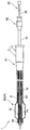
- FIG. 1 shows a side view (partial sectional view) of a light irradiation medical device according to an embodiment of the present invention.
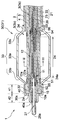
- FIG. 2 shows an enlarged cross-sectional view of the distal side of the light irradiation medical device shown in FIG.
- FIG. 3 shows a cross-sectional view of III-III of the light irradiation medical device shown in FIG.
- the light irradiation medical device 1 includes a shaft 2, a first tubular member 10, and a light guide device 20.
- the distal side of the light irradiation medical device 1 refers to the first end side in the longitudinal axis direction of the shaft 2 and the treatment target side.
- the proximal side of the light irradiation medical device 1 refers to the second end side of the shaft 2 in the longitudinal axis direction and the hand side of the user (operator).
- the proximal side may be referred to as a proximal portion and the distal side may be referred to as a distal portion.
- each member constituting the light irradiation medical device 1 has biocompatibility.
- the shaft 2 is a member having a first end and a second end in the longitudinal axis direction and having a lumen 3 extending in the longitudinal axis direction.
- the first end may correspond to the distal end of the shaft 2, and the second end may correspond to the proximal end of the shaft 2.
- the shaft 2 has a tubular structure for arranging the first tubular member 10 and the light guide device 20 in the cavity 3. Further, since the shaft 2 is inserted into the body, it preferably has flexibility.
- the shaft 2 is formed of, for example, a polyolefin resin (for example, polyethylene or polypropylene), a polyamide resin (for example, nylon), a polyester resin (for example, PET), an aromatic polyetherketone resin (for example, PEEK), a polyether polyamide resin, or a polyurethane. It can be composed of synthetic resins such as resins, polyimide resins and fluororesins (for example, PTFE, PFA, ETFE) and metals such as stainless steel, carbon steel and nickel titanium alloys. These may be used alone or in combination of two or more.
- the shaft 2 preferably contains a light-transmitting material.
- the light passes through the shaft 2, so that when the light guide device 20 (more preferably, the non-existent portion 24 of the clad of the optical fiber 21) is located inside the shaft 2, the light is efficiently emitted to the target tissue. Can be irradiated.
- the light-transmitting material include (meth) acrylic resin (for example, polymethylmethacrylate (PMMA)), polycarbonate resin (for example, polydiethylene glycol bisallyl carbonate (PC)), and polystyrene-based resin (for example, both methylmethacrylate and styrene).
- PMMA polymethylmethacrylate
- PC polydiethylene glycol bisallyl carbonate
- polystyrene-based resin for example, both methylmethacrylate and styrene
- synthetic resins such as polymerized resin (MS), acrylic nitrile styrene resin (SAN)), polyamide resin (for example, nylon),
- the shaft 2 preferably contains a light diffusing material.
- the light from the light guide device 20 is appropriately diffused when passing through the shaft 2, so that the target tissue can be evenly irradiated with the light.
- the light diffusible material include inorganic particles such as titanium oxide, barium sulfate and calcium carbonate, and organic particles such as crosslinked acrylic particles and crosslinked styrene particles.
- a first handle 61 for the operator to grip the device 1 is connected to the proximal portion of the shaft 2.
- the first handle 61 is provided with a fluid to be supplied to the inside of the balloon 31 through the cavity 3 of the shaft 2.
- a fluid feeder such as a syringe may be connected.
- the first tubular member 10 is arranged in the lumen 3 of the shaft 2 and is rotatable around a rotation axis parallel to the longitudinal axis direction of the shaft 2.
- a window 12 is provided on a part of the peripheral wall at the distal portion of the first tubular member 10.
- the light guide device 20 is arranged in the cavity 11 of the first tubular member 10 and is movable in the longitudinal axis direction of the shaft 2.
- the light guide device 20 has an optical fiber 21 extending in the longitudinal axis direction of the shaft 2.
- the optical fiber 21 has a core 22 and a clad 23 that covers the radial outer side of the core 22, and has a clad non-existing portion 24 in a part of the distal portion of the core 22.
- the emitted light from the light guide device 20 passes through the window 12. Since the window 12 through which the light emitted from the light guide device 20 passes is formed in the first tubular member 10, the first tubular member 10 is rotated or moved in the longitudinal axis direction of the shaft 2. , The irradiation position of the light emitted to the outside through the window 12 can be adjusted in the circumferential direction or the longitudinal axis direction of the shaft 2. Therefore, since the irradiation position of the emitted light can be adjusted without rotating the light guide device 20, damage to the light guide device 20 can be prevented.
- a guide wire used for delivering the shaft 2 to the target tissue can be inserted into the cavity 11 of the first tubular member 10. This makes it easier to move the light guide device 20 along the guide wire in the longitudinal axis direction of the shaft 2.
- the light irradiation medical device 1 may include a guide wire extending in the longitudinal axis direction of the shaft 2. The guide wire can be removed before the light guide device 20 is inserted into the cavity 11 of the first tubular member 10, and the light guide device 20 can be arranged in place of the guide wire.
- the optical fiber 21 of the light guide device 20 is a transmission line that transmits an optical signal to the target tissue.
- a connector 25 provided at the proximal end of the light guide device 20 is connected to a light source (not shown) such as a semiconductor laser.
- the optical fiber 21 has a core 22 and a clad 23 that covers the radial outer side of the core 22, and has a clad non-existing portion 24 in a part of the distal portion of the core 22.
- the materials constituting the core 22 and the clad 23 are not particularly limited, and glass such as plastic, quartz glass, and fluoride glass can be used.
- the non-existing portion 24 of the clad refers to a portion where the clad 23 does not exist at least in a part of the circumferential direction of the core 22, and serves as a light emitting area of the optical fiber 21.
- the side irradiation type light irradiation medical device 1 can be configured.
- the position where the clad non-existing portion 24 is provided in the longitudinal axis direction of the shaft 2 is not particularly limited as long as it is a part of the distal portion of the core 22, but is provided at the portion including the distal end 22a of the core 22. Is preferable. This makes it easier to form the non-existent portion 24 of the clad, and can also increase the flexibility at the distal end portion of the light guide device 20.
- the position of the distal end 24a of the non-existent portion 24 of the clad coincides with the position of the distal end 22a of the core 22. This eliminates the difficult step of forming the non-existing portion 24 of the clad while leaving the clad 23 of the portion including the distal end of the optical fiber 21, so that the step of forming the light emitting area of the optical fiber 21 can be facilitated. it can.
- the non-existent portion 24 of the clad can be formed by peeling the clad 23 by, for example, etching or polishing. It is more preferable to roughen the outer surface of the non-existing portion 24 of the clad by a method such as filing. Thereby, the light diffusivity can be improved.
- the light guide device 20 does not rotate about an axis parallel to the longitudinal axis direction of the shaft 2 with respect to the shaft 2. As a result, it is not necessary to rotate the optical fiber 21 when adjusting the light irradiation position, so that damage to the optical fiber 21 can be prevented.
- the first tubular member 10 is formed in a tubular shape having a distal portion and a proximal portion.
- the first tubular member 10 may have one or more lumens 11, but in order to reduce the outer diameter of the first tubular member 10, the first tubular member 10 has a lumen 11. It is preferable that only one is provided.
- the first tubular member 10 includes, for example, a polyolefin resin (for example, polyethylene or polypropylene), a polyamide resin (for example, nylon), a polyester resin (for example, PET), an aromatic polyetherketone resin (for example, PEEK), or a polyether. It can be composed of synthetic resins such as polyamide resin, polyurethane resin, polyimide resin and fluororesin (for example, PTFE, PFA, ETFE) and metals such as stainless steel, carbon steel and nickel titanium alloy. These may be used alone or in combination of two or more.
- the constituent materials of the shaft 2 and the first tubular member 10 may be the same or different from each other.
- the first tubular member 10 is made of a material having a lower transmittance of emitted light than the window 12. As a result, it becomes difficult for the emitted light to pass through a part of the peripheral wall of the distal portion of the first tubular member 10, that is, the portion where the window 12 is formed. Therefore, in the circumferential direction or the longitudinal axis direction of the shaft 2, The irradiation position of the light emitted to the outside through the window 12 can be adjusted. In order to improve the passability of the emitted light of the window 12 as compared with the first tubular member 10, for example, (i) a mode of opening the window 12 and (ii) a mode of arranging the transparent member 13 in the window 12 are used. Can be mentioned.
- the window 12 may be open, and the window 12 may communicate the inner cavity 11 of the first tubular member 10 with the outside of the shaft 2.
- the non-existing portion 24 of the clad of the light guide device 20 can be exposed to the outside from the window 12 of the first tubular member 10, so that light can be easily emitted directly from the window 12.
- the window 12 when the window 12 is open, it means that no other member is arranged in the window 12.
- FIG. 4 is a cross-sectional view showing a modified example of the device 1 shown in FIG.
- the window 12 is provided with the transparent member 13 that transmits the emitted light. This makes it possible to prevent liquids such as body fluids from entering the shaft 2.
- the transparent member 13 is arranged in the entire window 12.
- the transparent member 13 preferably has a higher transmittance than the portion of the first tubular member 10 in which the window 12 is not formed.
- the material constituting the transparent member 13 in addition to the resin constituting the first tubular member 10, for example, (meth) acrylic resin (for example, polymethylmethacrylate (PMMA)) and polycarbonate resin (for example, polydiethylene glycol bisallyl). It may be composed of a synthetic resin such as carbonate (PC)), polystyrene resin (for example, methyl methacrylate / styrene copolymer resin (MS), acrylic nitrile styrene resin (SAN)), polyamide resin (for example, nylon), and polyolefin resin. it can. These may be used alone or in combination of two or more.
- PC carbonate
- polystyrene resin for example, methyl methacrylate / styrene copolymer resin (MS), acrylic nitrile styrene resin (SAN)
- One or a plurality of windows 12 can be provided for one first tubular member 10, but in order to make it easier to adjust the irradiation position of the emitted light, the window 12 is provided for one first tubular member 10. It is preferable that only one is provided.
- the window 12 is preferably arranged on the proximal side of the distal end 10a of the first tubular member 10.
- the distal end 12a of the window 12 can be located within 10 cm of the distal end 10a of the first tubular member 10.
- the window 12 is provided only in a part of the shaft 2 in the circumferential direction. That is, it is preferable that the window 12 is not provided in the entire circumferential direction of the shaft 2. Above all, it is preferable that the window 12 is provided within a half circumference of the shaft 2, and the window 12 is provided within a quarter length of the entire circumference of the shaft 2 in the circumferential direction of the shaft 2. preferable. This makes it possible to selectively irradiate the emitted light in the circumferential direction of the shaft 2.
- the length of the window 12 in the longitudinal axis direction of the shaft 2 is larger than the length of the window 12 in the circumferential direction of the shaft 2. This makes it easier to irradiate the treated portion such as a lesion extending in the longitudinal axis direction of the biological tube wall.
- the window 12 is preferably longer than the non-existent portion 24 of the clad. As a result, the emitted light can be emitted from a wide range of the window 12 in the longitudinal axis direction of the shaft 2. For the same reason, when the balloon 31 is provided as the expansion portion 30 on the shaft 2, the window 12 is preferably longer than the straight pipe portion 33a of the balloon 31 in the longitudinal axis direction of the shaft 2.
- a reflective material that refracts the emitted light from the core 22 toward the window 12 is arranged on the inner surface of the first tubular member 10. It is more preferable that the reflective material is arranged on the inner peripheral wall surface of the first tubular member 10.
- a method of coating the inner surface of the first tubular member 10 with a coating agent containing a reflective material can be mentioned. Since the emitted light is easily collected due to the presence of the reflective material, the emitted light can be efficiently irradiated.
- the material of the reflective material include aluminum, gold, silver, copper, tin, titanium dioxide, tantalum pentoxide, aluminum oxide, silicon dioxide, magnesium fluoride or a combination thereof.
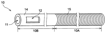
- FIG. 5 is a perspective view showing the overall configuration of the first tubular member 10 according to FIG. 1, and FIGS. 6 to 7 are perspective views showing a modified example of the first tubular member 10 shown in FIG. Represent.
- the first tubular member 10 may be composed of the resin tube 14 over the entire longitudinal axis direction. This facilitates the formation of the first tubular member 10.
- the first tubular member 10 has a first section 10A in which a reinforcing material containing metal is arranged.
- a reinforcing material containing metal is arranged on the first tubular member 10.
- the reinforcing material may be formed in layers, or may be a single wire or stranded wire arranged in a specific pattern, braided, or wound in a coil shape. As a result, the strength and torque of the shaft 2 can be increased.
- the first section 10A can be formed by arranging a reinforcing material on the outer surface, the inner surface, or the wall of the resin tube.
- the cross-sectional shape of the wire rod constituting the reinforcing material may be, for example, a circular shape, an oval shape, a polygonal shape, or a combination thereof.
- the oval shape includes an elliptical shape, an egg shape, and a rectangular shape with rounded corners.
- the description of the metal constituting the shaft 2 can be referred to.
- the type of structural pattern of the reinforcing material is not particularly limited, and the number of coil turns and the density are not particularly limited.
- the network structure and the coil may be formed at a constant density throughout the axial direction, or may be formed at a different density depending on the position in the axial direction.
- the first tubular member 10 may be a coil member 15 formed by spirally winding one or more wire rods.
- a first section 10A can be formed as a coreless coil by twisting a plurality of wires.
- the coil member is preferably a multi-layer coil in which a plurality of coils are stacked.
- the multi-layer coil can be formed, for example, by winding a wire rod around a core material to form a first coil, and then winding a wire rod on the first coil to further form a second coil. it can.
- the first tubular member 10 is further located on the distal side of the first section 10A and further has a second section 10B in which no reinforcing material is arranged, and the window 12 has a second section. It is preferably arranged in the section 10B and not in the first section 10A.
- the torque transmissibility of the first tubular member 10 can be enhanced by the reinforcing material existing in the first section 10A. Further, since the reinforcing material is not arranged in the second section 10B, it becomes easy to form the window 12 on the first tubular member 10.
- the second section 10B can be composed of, for example, a resin tube.
- the first tubular member 10 further has a third section 10C located proximal to the first section 10A, and the first tubular member 10 in the third section 10C.
- Reference numeral 10 is preferably a metal pipe 16.
- the rigidity of the first tubular member 10 can be gradually increased toward the handle side at hand.
- a plurality of annular grooves or spiral grooves may be formed on the outer surface of the pipe 16. Above all, it is preferable that the groove is formed on the outer surface on the distal side of the center of the pipe 16 in the longitudinal axis direction.
- a second handle 62 for gripping by the operator is connected to the proximal portion of the first tubular member 10.
- the second handle 62 it becomes easy to perform the movement operation of the first tubular member 10 in the longitudinal axis direction and the rotation operation with the direction parallel to the longitudinal axis direction of the shaft 2 as the rotation axis.
- the first tubular member 10 has a position display portion 17 indicating the position of the window 12 at its distal end. This makes it easier to grasp the position of the window 12, so that the treated portion such as a lesion can be reliably irradiated with the emitted light.
- Examples of the position display unit 17 include scales, letters, numbers, symbols, and figures.
- the scale is a combination of an axis extending along the longitudinal direction or the circumferential direction of the first tubular member 10 and at least one of a straight line, a curve, a diagonal line, and a point intersecting the axis. You may.
- the position display unit 17 may be a colored portion of the outer surface of the first tubular member 10, or a portion in which a pigment such as a pigment is mixed with the resin constituting the first tubular member 10. May be.
- Only one position display unit 17 may be provided for one first tubular member 10, or a plurality of position display units 17 may be provided.
- the position display units 17 are provided on both sides of the window 12 in the longitudinal axis direction of the first tubular member 10. This makes it easier to grasp the position of the window 12 in the longitudinal axis direction of the first tubular member 10.
- the position display unit 17 may be provided at a position overlapping the window 12 in the longitudinal axis direction of the first tubular member 10. Further, the position display units 17 may be provided on both sides of the window 12 in the circumferential direction. This makes it easier to grasp the position of the window 12 in the circumferential direction of the first tubular member 10.
- the light guide device 20 has a second tubular member 26 that covers the optical fiber 21 and has light transmission.
- the optical fiber 21 can be reinforced.
- a diffusing agent such as titanium oxide
- the second tubular member 26 is a tubular member extending in the longitudinal axis direction of the optical fiber 21.
- the second tubular member 26 covers the entire longitudinal direction of the optical fiber 21.
- the entire optical fiber 21 is protected, so that damage, deformation, and breakage of the core 22 can be suppressed.
- the second tubular member 26 covers the entire circumferential direction of the optical fiber 21.
- the distal end 26a of the second tubular member 26 is preferably located distal to the distal end of the optical fiber 21, and is located distal to the distal end 22a of the core 22. It is more preferable to have. This makes it possible to prevent deformation or damage at the distal end of the optical fiber 21.
- the second tubular member 26 may have light transmittance, but is preferably made of resin.
- the resin constituting the second tubular member 26 include polyamide-based resin, polyester-based resin, polyurethane-based resin, polyolefin-based resin, fluorine-based resin, vinyl chloride-based resin, silicone-based resin, and natural rubber. Only one of these may be used, or two or more thereof may be used in combination. Of these, polyamide-based resins, polyester-based resins, polyurethane-based resins, polyolefin-based resins, and fluororesins are preferably used.
- a photodiffusive material of inorganic particles such as titanium oxide, barium sulfate and calcium carbonate, and organic particles such as crosslinked acrylic particles and crosslinked styrene particles is added to the resin constituting the second tubular member 26. be able to.
- the second tubular member 26 has an inner diameter of a certain size in the longitudinal axis direction of the optical fiber 21 so that the optical fiber 21 can be easily inserted into the cavity 27 of the second tubular member 26.
- the outer diameter of the second tubular member 26 is set so that the light guide device 20 can easily move in the longitudinal axis direction of the optical fiber 21 in the cavity 3 of the shaft 2.
- the outer diameter of the second tubular member 26 may become smaller toward the distal end, or may have a constant size in the longitudinal axis direction of the optical fiber 21.
- the non-existent portion 24 of the clad is preferably covered with the second tubular member 26, and the non-existent portion 24 of the clad is covered with the second tubular member 26 over the entire longitudinal direction of the optical fiber 21. Is more preferable. As a result, the portion of the core 22 corresponding to the non-existing portion 24 of the clad is protected, so that damage, deformation, and breakage of the core 22 at a position corresponding to the non-existing portion 24 of the clad can be suppressed.
- a resin chip may be provided at the distal end of the second tubular member 26.
- the radiation opaque marker arranged in the cavity 27 of the second tubular member 26 is less likely to fall off from the distal end surface side of the light guide device 20.
- the resin chips can be formed into, for example, hemispherical, semi-elliptical, cylindrical, and polygonal columns. It is preferable that a part of the resin chip is arranged in the cavity 27 of the second tubular member 26. Further, the resin tip is preferably in the shape of a plug inserted into the cavity 27 of the second tubular member 26.
- the material constituting the resin chip the same material as the material constituting the second tubular member 26 can be adopted.
- an expansion portion 30 that expands outward in the radial direction of the shaft 2 is further provided at the distal portion of the shaft 2.
- the device 1 can be easily fixed to the body, for example, the wall of the biological tube by expanding the expansion portion 30, so that the displacement of the device 1 in the body can be prevented.
- FIG. 8 shows a cross-sectional view showing a modified example of the light irradiation medical device 1 shown in FIG.
- the expansion 30 is preferably a balloon, a basket with a plurality of elastic wires, or a stent, and the expansion 30 is more preferably a balloon, a basket with a plurality of elastic wires, or a self-expanding stent. preferable. Since the expansion portion 30 is a balloon 31, even if the expansion portion 30 comes into contact with the living tube wall, the position in the body can be fixed without damaging the living tube wall.
- FIG. 2 shows an example in which the expansion portion 30 is a balloon 31
- FIG. 8 shows an example in which the expansion portion 30 is a stent 35
- FIG. 8 shows a schematic representation of the outer shape of the stent 35. Is.
- the balloon 31 has, in order from the distal side, a distal side fixing portion 32 fixed to the shaft 2, an expanding portion 33 not fixed to the shaft 2, and a proximal side fixing portion 34 fixed to the shaft 2. And may have.
- the shaft 2 is composed of an inner tube 4 and an outer tube 5, and at the distal portion of the shaft 2, the inner tube 4 extends from the distal end of the outer tube 5 to extend the balloon 31 in the longitudinal axis direction of the shaft 2. It is preferable that it penetrates. By configuring the shaft 2 and the balloon 31 in this way, the balloon 31 can be joined to the shaft 2.
- the expansion portion 30 is a balloon 31, it is preferable that a fluid feeder (not shown) is connected to the proximal portion of the shaft 2.
- the balloon 31 is configured so that a pressure fluid is supplied from the fluid feeder to the inside of the balloon 31 through the shaft 2, and the pressure fluid is supplied to the inside of the balloon 31 so that the balloon 31 can be expanded. ..
- the balloon 31 can be contracted by drawing the pressure fluid from the inside of the balloon 31.
- the balloon 31 is expanded, the outer surface of the balloon 31 comes into contact with the wall of a biological tube such as a blood vessel or a digestive tract, so that the shaft 2 can be fixed in the body.
- the shaft 2 may have a plurality of lumens 3.
- the shaft 2 may have a first cavity 3a through which the first tubular member 10 and the light guide device 20 are inserted, and a second cavity 3b communicating with the balloon 31. ..
- the first cavity 3a can function as an insertion passage for the light guide device 20
- the second lumen 3b can function as a flow path for the pressure fluid that expands and contracts the balloon 31.
- the shaft 2 is composed of an inner tube 4 and an outer tube 5, the inner tube 4 is the first inner tube 3a, and the space between the inner tube 4 and the outer tube 5 is the second inner tube. It may be the cavity 3b.
- the inflated portion 33 of the balloon 31 may have a straight pipe portion 33a and a tapered portion 33b formed in the distal portion and the proximal portion of the straight pipe portion 33a, respectively.
- the shaft 2 can be fixed inside the body by bringing the outer surface of the straight tube portion 33a of the balloon 31 into contact with the living tube wall.
- the balloon 31 is preferably made of resin.
- the resin constituting the balloon 31 include a polyamide resin, a polyester resin, a polyurethane resin, a polyolefin resin, a vinyl chloride resin, a silicone resin, and a natural rubber. Only one of these may be used, or two or more thereof may be used in combination. Of these, polyamide-based resins, polyester-based resins, and polyurethane-based resins are preferably used. As these resins, an elastomer resin can be used from the viewpoint of thinning the balloon 31 and flexibility.
- the type of fluid supplied into the balloon 31 is not particularly limited, and for example, a liquid such as physiological saline, a contrast medium, or a mixture thereof, or a gas such as air, nitrogen, or carbon dioxide can be used. Considering the transparency of the emitted light, it is preferable that a gas is supplied into the balloon 31.
- the basket is formed by binding a plurality of elastic wires at the first binding portion and the second binding portion on the proximal side of the first binding portion.
- the elastic wire is bent or spirally twisted between the first binding portion and the second binding portion.
- the basket is generally provided for catching foreign substances such as stones, but in the present invention, it is used for fixing the position of the device 1 in the body.
- the elastic wire is a wire having elasticity, and is preferably composed of a shape memory alloy or a shape memory resin.
- the elastic wire is, for example, a single wire or stranded wire composed of stainless steel such as SUS304 and SUS316, platinum, nickel, cobalt, chromium, titanium, tungsten, aluminum, gold, silver, Ni—Ti alloy, Co—Cr alloy and the like. It may be a metal wire rod of.
- the number of elastic wires is not particularly limited and can be selected according to the inner diameter of the living tube wall and the like.
- the elastic wire is fixed to the shaft 2.
- the distal or proximal ends of the plurality of elastic wires are spaced apart in the circumferential direction of the shaft 2 and the distal or proximal ends of the elastic wires are brazed or glued to the shaft 2 or
- the elastic wire can be fixed to the shaft 2 by covering the distal end or the proximal end of the elastic wire with a tubular connector and crimping the connector.
- the stent 35 is a structure that can be expanded in diameter and is composed of a mesh structure such as a mesh, and includes a plurality of columns.
- the stent 35 can be formed from a pattern of interconnected structural elements that expand and contract, for example, in the circumferential and axial directions.
- the stent 35 is a coil type made of one linear metal or polymer material, a type obtained by cutting out a metal tube or a tube made of a polymer material with a laser or the like, and a type assembled by welding linear parts. , A type made by weaving a plurality of linear metals, and the like.
- Stent 35 can be classified into balloon expansion type and self-expansion type from the viewpoint of expansion mechanism.
- a stent is mounted on the outer surface of the balloon and transported to a treatment portion such as a lesion, and the stent is expanded at the treatment portion using a balloon.
- the stent expands by itself by transporting the stent to the lesion portion by a catheter having a member that suppresses expansion and removing the member that suppresses expansion at the treatment portion.
- the stent 35 provided on the shaft 2 is preferably a self-expanding stent. Since the self-expanding type does not need to provide a balloon inside, the diameter in the reduced diameter state can be made smaller than that of the balloon expanding type.
- the description of the constituent material of the elastic wire of the basket can be referred to.
- the expansion portion 30 is a self-expansion type stent
- the proximal end portion of the self-expansion type stent is fixed to the distal end portion of the shaft 2.
- the device 1 can be fixed in the body without the stent 35 inhibiting the emission of light.
- the distal end of the self-expanding stent is distal to the shaft 2. It is preferable that it is not fixed to the end. As a result, the shaft 2 can be fixed in the body by bringing the distal end portion of the self-expandable stent into contact with the living tube wall.
- the stent 35 can be fixed to the shaft 2 in the same manner as the elastic wire of the basket is fixed to the shaft 2.
- a plurality of struts are spaced apart in the circumferential direction of the shaft 2 and brazed or glued to the shaft 2, or a tubular connection from above the proximal end of the struts.
- a method such as covering the tool and crimping the connector can be adopted.
- the device 1 When the expansion portion 30 is a basket or a stent 35, it is preferable that the device 1 further has a third tubular member (not shown) capable of accommodating the expansion portion 30 in the lumen.
- the basket or the stent 35 expands in the endoscope until the device 1 is transported from the forceps opening of the endoscope through the forceps channel to the vicinity of the treatment part such as a lesion. It is possible to prevent damage to the forceps opening, the forceps channel, internal tissues other than foreign substances, and the like.
- the expansion portion 30 may be arranged at a position overlapping the non-existing portion 24 of the clad in the longitudinal axis direction of the shaft 2. Further, as shown in FIG. 8, the expansion portion 30 may be arranged on the distal side of the non-existing portion 24 of the clad in the longitudinal axis direction of the shaft 2.
- the expansion portion 30 When the expansion portion 30 is provided at a position overlapping the non-existing portion 24 of the clad in the longitudinal axis direction of the shaft 2, the expansion portion 30 preferably contains a light-transmitting material. In that case, it is more preferable that both the portion of the shaft 2 covered by the expansion portion 30 and the expansion portion 30 are made of a light-transmitting material. As a result, when the non-existing portion 24 of the clad is located inside the expansion portion 30, the target tissue can be efficiently irradiated with light at the position corresponding to the balloon 31. As the light transmissive material, the description of the shaft 2 can be referred to.
- the expansion portion 30 When the expansion portion 30 is provided at a position overlapping the non-existing portion 24 of the clad in the longitudinal axis direction of the shaft 2, the expansion portion 30 preferably contains a light diffusing material. In that case, it is more preferable that both the portion of the shaft 2 covered by the expansion portion 30 and the expansion portion 30 are made of a light diffusing material. By imparting light diffusivity to these members, it is possible to evenly irradiate the target tissue with light. As the light diffusing material, the description of the shaft 2 can be referred to.
- a support portion 40 for supporting the distal portion of the light guide device 20 is further provided at the distal end portion of the shaft 2. As a result, it is possible to suppress the hanging of the distal portion of the light guide device 20 due to gravity, so that the rotation operation of the first tubular member 10 and the movement operation of the shaft 2 of the light guide device 20 in the longitudinal axis direction are performed. It will be easier.
- the support portion 40 may be provided on the outer side in the radial direction of the shaft 2, or may be arranged in the lumen 3 of the shaft 2 as shown in FIG. Further, in order to reliably support the light guide device 20 by the support portion 40, a part of the support portion 40 is arranged on the distal side of the distal end 2a of the shaft 2 as shown in FIGS. 1 to 2. May be good.
- the support portion 40 can be formed in a tubular shape. As shown in FIG. 8, the tubular support portion 40 may have a constant inner diameter in the longitudinal axis direction of the shaft 2. Further, as shown in FIGS. 1 to 2, the tubular support portion 40 may have an inner diameter that differs depending on the position of the shaft 2 in the longitudinal axis direction. For example, the tubular support portion 40 is located on the distal side of the large diameter portion 41 that supports the shaft 2 and the large diameter portion 41, and supports the light guide device 20, and supports the light guide device 20. It may have a small diameter portion 42 having an inner diameter smaller than that of the small diameter portion 42. As a result, the effect of suppressing the hanging of the light guide device 20 due to gravity can be further enhanced. For the same reason, the tubular support portion 40 may be formed in a tapered shape in which the inner diameter decreases toward the distal side.
- the description of the material constituting the shaft 2 can be referred to.
- the distal end 40a of the support portion 40 is the distal end of the extension portion 30. It is preferably located distal to the end 30a. Further, as shown in FIG. 8, when the expansion portion 30 is located distal to the non-existing portion 24 of the clad in the longitudinal axis direction of the shaft 2, the distal end 40a of the support portion 40 is the expansion portion. It may be located proximal to the distal end 30a of 30.
- a radiation opaque marker may be provided on each member constituting the light irradiation medical device 1.
- the first radiation opaque marker 51 may be arranged at the distal portion of the shaft 2.
- the position of the shaft 2 can be specified under fluoroscopy, so that the shaft 2 can be aligned with the position of the tissue to be irradiated.
- the second radiation opaque marker 52 may be arranged on the second tubular member 26 on the distal side of the distal end of the core 22.
- the third radiation opaque marker 53 may be arranged on the second tubular member 26 on the proximal side of the proximal end of the non-existent portion 24 of the clad.
- the radiation opaque markers are arranged on both sides of the non-existing portion 24 of the clad which is the light emitting area in the longitudinal axis direction of the second tubular member 26, so that the position of the light emitting area can be more specified under fluoroscopy. It will be easier.
- a fourth radiation opaque marker 54 may be further arranged on the proximal side of the shaft 2 with respect to the first radiation opaque marker 51. This makes it easier to identify the position of the shaft 2 in the longitudinal axis direction under fluoroscopy.
- the fifth radiation opaque marker 55 is arranged at the distal portion of the first tubular member 10, and the fifth radiation opaque marker 55 is located distal to the window 12 of the first tubular member 10. It is more preferable that they are arranged. Further, it is preferable that the sixth radiation opaque marker 56 is arranged at the distal portion of the first tubular member 10 and proximal to the window 12. This makes it easier to grasp the position of the window 12 in the longitudinal axis direction of the first tubular member 10, and thus makes it easier to specify the position of the light emitting area under fluoroscopy.
- the second radiation opaque marker is sequentially provided from the distal side to the proximal side. It is preferable that the distal end of the transmission marker 52, the distal end of the fifth radiation opaque marker 55, and the distal end of the first radiation opaque marker 51 are located. By locating the markers in this way, it becomes easy to grasp the positions of the shaft 2, the non-existent portion 24 of the clad, and the window 12.
- the direction is from the proximal side to the distal side for the same reason as described above. It is preferable that the proximal end of the third radiation opaque marker 53, the proximal end of the sixth radiation opaque marker 56, and the proximal end of the fourth radiation opaque marker 54 are located in this order.
- the shape of the radiation opaque marker is not particularly limited, but may be, for example, an annular shape or a rod shape. Further, the radiation opaque marker may have a coil shape or may have a C-shaped cross section having a slit in the ring. When the radiation opaque marker is annular or coiled, it is easy to attach the marker to the outside of the shaft 2, the first tubular member 10 or the second tubular member 26. When the radiation opaque marker has a rod shape or a coil shape, it becomes easy to place the marker in the cavity 3 of the shaft 2, the cavity 11 of the first tubular member 10, or the lumen 27 of the second tubular member 26.
- the radiation opaque marker is preferably composed of a material containing a metal material such as platinum, gold, silver, tungsten, tantalum, iridium, palladium and an alloy thereof.
- the radiation opaque marker may be a metal marker made of the above-mentioned metal material, or may be a resin marker made of the above-mentioned metal material.
Landscapes
- Health & Medical Sciences (AREA)
- Biomedical Technology (AREA)
- Engineering & Computer Science (AREA)
- Life Sciences & Earth Sciences (AREA)
- Nuclear Medicine, Radiotherapy & Molecular Imaging (AREA)
- Animal Behavior & Ethology (AREA)
- Veterinary Medicine (AREA)
- Public Health (AREA)
- General Health & Medical Sciences (AREA)
- Physics & Mathematics (AREA)
- Surgery (AREA)
- Pathology (AREA)
- Radiology & Medical Imaging (AREA)
- Otolaryngology (AREA)
- Molecular Biology (AREA)
- Medical Informatics (AREA)
- Heart & Thoracic Surgery (AREA)
- Electromagnetism (AREA)
- Optics & Photonics (AREA)
- Biophysics (AREA)
- Media Introduction/Drainage Providing Device (AREA)
- Laser Surgery Devices (AREA)
- Radiation-Therapy Devices (AREA)
Abstract
長手軸方向に第1端と第2端を有するシャフト(2)であって、長手軸方向に延在している内腔(3)を有するシャフト(2)と、内腔(3)に配置され、シャフト(2)の長手軸方向に平行な回転軸周りに回転可能であり、遠位部の周壁の一部に窓(12)が設けられている第1筒状部材(10)と、第1筒状部材(10)の内腔(11)に配置され、シャフト(2)の長手軸方向に移動可能な導光装置と、を備え、導光装置は、シャフト(2)の長手軸方向に延在している光ファイバー(21)を有し、光ファイバー(21)は、コア(22)と、コア(22)を被覆するクラッド(23)と、コア(22)の遠位部の一部にクラッドの非存在部(24)と、を有しており、導光装置からの射出光が窓(12)を通過する光照射医療装置(1)。
Description
本発明は、血管や消化管等の体内管腔において、がん細胞等の組織に光を照射するための光照射医療装置に関するものである。
光線力学的療法(Photodynamic Therapy:PDT)では、光増感剤を静脈注射や腹腔内投与で体内に投与し、がん細胞等の対象組織に光増感剤を集積させ、特定の波長の光を照射することにより光増感剤を励起させる。励起された光増感剤が基底状態に戻るときにエネルギー転換が生じ、活性酸素種を発生させる。活性酸素種が対象組織を攻撃することにより、対象組織を除去することができる。また、レーザー光を用いたアブレーション(組織焼灼)では、対象組織にレーザー光を照射し、焼灼することが行われる。
PDTや光アブレーションで使用する光照射医療装置では、対象組織に光を照射するためにカテーテル管内に光ファイバーが配置される。
特許文献1には、規定された領域に照射を供給する、規定された処置ウィンドウを有するバルーンカテーテルを含む装置が開示されている。この装置は、中央チャネルと、外部スリーブとを含んでいる。中央チャネルは、光ファイバープローブが挿入され得る透明なものである。外部スリーブは、該バルーンを膨張させるために用いる、近位端と遠位端とを有する外部スリーブであって、該遠位端近傍に膨張可能バルーンをさらに含み、該バルーンが両端部において、処置ウィンドウを規定するために反射材料でコーティングされている。
特許文献2には、シャフトと、バルーンと、第1ルーメンと、第2ルーメンと、導光材と、拡散部材と、管状部材と、を具備するアブレーションデバイスが開示されている。バルーンは、上記シャフトの先端側に設けられており、弾性的に膨張可能である。第1ルーメンは、上記シャフトに沿って形成されており、上記バルーンへ流体を流入させるためのものである。第2ルーメンは、上記シャフトに沿って形成されており、上記バルーンから流体を流出させるためのものである。導光材は、上記シャフトに沿って設けられており、上記バルーン内へレーザー光を導く。拡散部材は、上記バルーン内において上記導光材から出射されるレーザー光を上記導光材が延出された第1方向と交差する方向へ反射又は拡散させる。管状部材は上記バルーン内に設けられて上記拡散部材を囲繞しており、その内面側に上記拡散部材により反射又は拡散されたレーザー光を反射又は遮断する反射層を有し、かつ当該レーザー光を当該反射層の外側へ透過させる透過窓を有する。
特許文献3には、前立腺障害を治療するための光線力学的療法において、光線感作物質が送達装置を利用して投与されることが開示されている。送達装置は、その内部にガイドワイヤーを挿入可能に受け入れるチャネルを含んでいる。活性化エネルギーは、エネルギー源と、その内部にガイドワイヤーを挿入可能に受け入れるチャネルとを含んだ照射装置を利用して送達される。ガイドワイヤーは、送達装置及び/又は照射装置を位置決めするのに利用される。また、特許文献3には照射装置をガイドワイヤーに沿って側面方向に滑らせる、すなわち回転させることができることも開示されている。
しかしながら、上記特許文献1に記載の装置では、バルーンに設けられた処置ウィンドウによって光の照射位置が決定される。このため、一旦、バルーンを拡張して体内に固定した後に照射位置を変更するには、バルーンを収縮させた上でカテーテルを遠位側または近位側に移動、あるいは回転させる必要があり煩雑であった。また、特許文献2に記載の装置では、導光材(光ファイバー)に接続された管状部材に設けられている透過窓によって光の照射位置が決定される。このため、照射位置を調整するためには、導光材を遠位側または近位側に移動、あるいは回転させる必要があり、この動作により導光材が損傷するおそれがあった。さらに、特許文献3に記載の照射装置も回転させることが可能であるため、照射装置が損傷するおそれがあった。そこで、本発明は、導光装置の損傷を防ぎながら、射出光の照射位置を調整することができる光照射医療装置を提供することを目的とするものである。
上記目的を達成し得た本発明の光照射医療装置の一実施態様は、長手軸方向に第1端と第2端を有するシャフトであって、長手軸方向に延在している内腔を有するシャフトと、シャフトの内腔に配置され、シャフトの長手軸方向に平行な回転軸周りに回転可能であり、遠位部の周壁の一部に窓が設けられている第1筒状部材と、第1筒状部材の内腔に配置され、シャフトの長手軸方向に移動可能な導光装置と、を備え、導光装置は、長手軸方向に延在している光ファイバーを有し、光ファイバーは、コアと、コアの径方向外方を被覆するクラッドとを有し、かつ、コアの遠位部の一部にクラッドの非存在部を有しており、導光装置からの射出光が窓を通過する点に要旨を有する。上記光照射医療装置では、導光装置からの射出光が通過する窓が第1筒状部材に形成されている。第1筒状部材を回転またはシャフトの長手軸方向に移動させることによって、シャフトの周方向または長手軸方向において、窓を通じて外に射出される光の照射位置を調整することができる。したがって、導光装置を回転させなくても射出光の照射位置を調整することができるため、導光装置の損傷を防ぐことができる。
上記光照射医療装置において、第1筒状部材は、窓よりも射出光の通過性が低い材料から構成されていることが好ましい。
上記光照射医療装置において、窓には、射出光を透過する透明部材が配置されていることが好ましい。
上記光照射医療装置において、シャフトの周方向における窓の長さよりもシャフトの長手軸方向における窓の長さが大きいことが好ましい。
上記光照射医療装置において、窓はシャフトの周方向においてシャフト全周の4分の1の長さの範囲内に設けられていることが好ましい。
上記光照射医療装置において、シャフトの遠位部に、シャフトの径方向外方に向かって拡張する拡張部がさらに設けられていることが好ましい。
上記光照射医療装置において、拡張部は、バルーン、複数の弾性ワイヤを備えたバスケット、または自己拡張型ステントであることが好ましい。
上記光照射医療装置において、第1筒状部材は、金属を含む補強材が配置されている第1区間を有していることが好ましい。
上記光照射医療装置において、第1筒状部材は、第1区間よりも遠位側に位置し、補強材が配置されていない第2区間をさらに有し、窓は、第2区間に配され、第1区間には配されていないことが好ましい。
上記光照射医療装置において、第1筒状部材は、第1区間よりも近位側に位置している第3区間をさらに有しており、第3区間において第1筒状部材は金属製のパイプであることが好ましい。
上記光照射医療装置において、シャフトの遠位端部に、導光装置の遠位部を支持する支持部がさらに設けられていることが好ましい。
上記光照射医療装置は、シャフトの長手軸方向において、窓がクラッドの非存在部よりも長いことが好ましい。
上記光照射医療装置において、第1筒状部材の内面にコアからの射出光を窓に向かって屈折させる反射材が配置されていることが好ましい。
上記光照射医療装置において、導光装置は、光ファイバーを覆いかつ光透過性を有する第2筒状部材を有することが好ましい。
上記光照射医療装置において、第1筒状部材は、その遠位端部に窓の位置を示す位置表示部を有していることが好ましい。
上記光照射医療装置において、導光装置は、シャフトに対してシャフトの長手軸方向に平行な軸周りに回転しないことが好ましい。
上記光照射医療装置では、導光装置からの射出光を通過させる窓が第1筒状部材に形成されている。このため、第1筒状部材を回転またはシャフトの長手軸方向に移動させることによって、シャフトの周方向または長手軸方向において、窓を通じて外に射出される光の照射位置を調整することができる。したがって、導光装置を回転させなくても射出光の照射位置を調整することができるため、導光装置の損傷を防ぐことができる。
以下、下記実施の形態に基づき本発明をより具体的に説明するが、本発明はもとより下記実施の形態によって制限を受けるものではなく、前・後記の趣旨に適合し得る範囲で適当に変更を加えて実施することも勿論可能であり、それらはいずれも本発明の技術的範囲に包含される。なお、各図面において、便宜上、ハッチングや部材符号等を省略する場合もあるが、かかる場合、明細書や他の図面を参照するものとする。また、図面における種々部材の寸法は、本発明の特徴の理解に資することを優先しているため、実際の寸法とは異なる場合がある。
本発明の光照射医療装置の一実施態様は、長手軸方向に第1端と第2端を有するシャフトであって、長手軸方向に延在している内腔を有するシャフトと、シャフトの内腔に配置され、シャフトの長手軸方向に平行な回転軸周りに回転可能であり、遠位部の周壁の一部に窓が設けられている第1筒状部材と、第1筒状部材の内腔に配置され、シャフトの長手軸方向に移動可能な導光装置と、を備え、導光装置は、シャフトの長手軸方向に延在している光ファイバーを有し、光ファイバーは、コアと、コアの径方向外方を被覆するクラッドとを有し、かつ、コアの遠位部の一部にクラッドの非存在部を有しており、導光装置からの射出光が窓を通過する点に要旨を有する。上記光照射医療装置では、導光装置からの射出光が通過する窓が第1筒状部材に形成されている。このため、第1筒状部材を回転またはシャフトの長手軸方向に移動させることによって、シャフトの周方向または長手軸方向において、窓を通じて外に射出される光の照射位置を調整することができる。したがって、導光装置を回転させなくても射出光の照射位置を調整することができるため、導光装置の損傷を防ぐことができる。
光照射医療装置は、PDTや光アブレーションにおいて血管や消化管等の体内管腔で、がん細胞等の対象組織である処置部に対して特定の波長の光を照射するために用いられる。光照射医療装置は、単独で処置部まで送達されるものであってもよく、送達用のカテーテルや内視鏡と共に用いられてもよい。内視鏡を用いた治療では、内視鏡の鉗子口を通じて光照射医療装置が体内に配置され、処置部まで送達される。以下では光照射医療装置を単に装置と称することがある。
図1~図3を参照しながら、光照射医療装置の基本構成について説明する。図1は、本発明の一実施形態に係る光照射医療装置の側面図(一部断面図)を表す。図2は、図1に示した光照射医療装置の遠位側を拡大した断面図を表す。図3は、図2に示した光照射医療装置のIII-III断面図を表す。光照射医療装置1は、シャフト2と、第1筒状部材10と、導光装置20と、を備えている。
本発明において、光照射医療装置1の遠位側とは、シャフト2の長手軸方向の第1端側であって処置対象側を指す。光照射医療装置1の近位側とは、シャフト2の長手軸方向の第2端側であって使用者(術者)の手元側を指す。各部材をその長手軸方向で二等分割したときの近位側を近位部、遠位側を遠位部と称することがある。
光照射医療装置1を構成する各部材の材料は生体適合性を有することが望ましい。
シャフト2は、長手軸方向に第1端と第2端を有しており、長手軸方向に延在している内腔3を有している部材である。なお、第1端はシャフト2の遠位端に相当し、第2端はシャフト2の近位端に相当してもよい。シャフト2は、その内腔3に第1筒状部材10および導光装置20を配置するために管状構造を有している。また、シャフト2は体内に挿入されるものであるため、好ましくは可撓性を有している。
シャフト2は、例えば、ポリオレフィン樹脂(例えば、ポリエチレンやポリプロピレン)、ポリアミド樹脂(例えば、ナイロン)、ポリエステル樹脂(例えば、PET)、芳香族ポリエーテルケトン樹脂(例えば、PEEK)、ポリエーテルポリアミド樹脂、ポリウレタン樹脂、ポリイミド樹脂、フッ素樹脂(例えば、PTFE、PFA、ETFE)等の合成樹脂や、ステンレス鋼、炭素鋼、ニッケルチタン合金等の金属から構成することができる。これらは一種のみを単独で用いてもよく、二種以上を組み合わせて用いてもよい。
シャフト2は、光透過性の材料を含んでいることが好ましい。これにより、光がシャフト2を透過するため、シャフト2の内部に導光装置20(より好ましくは光ファイバー21のクラッドの非存在部24)が位置したときに、対象組織に対して効率よく光を照射することができる。光透過性の材料としては、(メタ)アクリル樹脂(例えば、ポリメチルメタクリレート(PMMA))、ポリカーボネート樹脂(例えば、ポリジエチレングリコールビスアリルカーボネート(PC))、ポリスチレン系樹脂(例えば、メチルメタクリレート・スチレン共重合樹脂(MS)、アクリロニトリルスチレン樹脂(SAN))、ポリアミド樹脂(例えば、ナイロン)、ポリオレフィン樹脂等の合成樹脂を挙げることができる。
シャフト2は、光拡散性の材料を含んでいることが好ましい。これにより、導光装置20からの光がシャフト2の通過時に適度に拡散されるため、対象組織に対して光をムラなく照射することができる。光拡散性の材料としては、酸化チタン、硫酸バリウム、炭酸カルシウム等の無機系粒子、架橋アクリル系粒子、架橋スチレン系粒子等の有機系粒子が挙げられる。
図1に示すように、シャフト2の近位部には、術者が装置1を把持するための第1ハンドル61が接続されていることが好ましい。シャフト2の遠位部に後述する拡張部30が設けられ、拡張部30がバルーン31である場合、第1ハンドル61には、シャフト2の内腔3を通じてバルーン31の内部に流体を供給するためのシリンジ等の流体供給器が接続されていてもよい。
第1筒状部材10は、シャフト2の内腔3に配置され、シャフト2の長手軸方向に平行な回転軸周りに回転可能なものである。第1筒状部材10の遠位部の周壁の一部には窓12が設けられている。導光装置20は、第1筒状部材10の内腔11に配置され、シャフト2の長手軸方向に移動可能なものである。導光装置20は、シャフト2の長手軸方向に延在している光ファイバー21を有する。光ファイバー21は、コア22と、コア22の径方向外方を被覆するクラッド23とを有し、かつ、コア22の遠位部の一部にクラッドの非存在部24を有している。導光装置20からの射出光は窓12を通過する。このように導光装置20からの射出光が通過する窓12が第1筒状部材10に形成されているため、第1筒状部材10を回転またはシャフト2の長手軸方向に移動させることによって、シャフト2の周方向または長手軸方向において、窓12を通じて外に射出される光の照射位置を調整することができる。したがって、導光装置20を回転させなくても射出光の照射位置を調整することができるため、導光装置20の損傷を防ぐことができる。
導光装置20を挿通する前に、第1筒状部材10の内腔11にはシャフト2を対象組織まで送達するために用いられるガイドワイヤーを挿通することができる。これにより、ガイドワイヤーに沿って導光装置20をシャフト2の長手軸方向に移動させやすくなる。図示していないが、光照射医療装置1は、シャフト2の長手軸方向に延在しているガイドワイヤーを含んでいてもよい。導光装置20を第1筒状部材10の内腔11に挿通する前にガイドワイヤーを抜去し、ガイドワイヤーの代わりに導光装置20を配置することができる。
導光装置20の光ファイバー21は対象組織まで光信号を送信する伝送路である。導光装置20の近位端に設けられたコネクタ25は、半導体レーザー等の光源(図示していない)に接続される。光ファイバー21は、コア22と、コア22の径方向外方を被覆するクラッド23とを有し、かつ、コア22の遠位部の一部にクラッドの非存在部24を有している。コア22およびクラッド23を構成する材料は特に限定されず、プラスチック、石英ガラス、ふっ化物ガラス等のガラスを用いることができる。
クラッドの非存在部24は、コア22の周方向の少なくとも一部でクラッド23が存在していない部分を指し、光ファイバー21の発光エリアとなる。このようなクラッドの非存在部24を設けることによって、側面照射型の光照射医療装置1を構成することができる。
シャフト2の長手軸方向においてクラッドの非存在部24が設けられる位置はコア22の遠位部の一部であれば特に制限されないが、コア22の遠位端22aを含む部分に設けられていることが好ましい。これによりクラッドの非存在部24を形成しやすくなり、導光装置20の遠位端部での柔軟性も高めることができる。
図2に示すように、クラッドの非存在部24の遠位端24aの位置は、コア22の遠位端22aの位置と一致していることが好ましい。これにより、光ファイバー21の遠位端を含む部分のクラッド23を残しながらクラッドの非存在部24を形成するという難しい工程が不要になるため、光ファイバー21の発光エリアの形成工程を容易にすることができる。
クラッドの非存在部24は、例えばエッチングや研磨によってクラッド23を剥離させることで形成することができる。やすり掛けなどの方法によりクラッドの非存在部24の外側表面を荒らすことがより好ましい。これにより、光拡散性を向上させることができる。
導光装置20は、シャフト2に対してシャフト2の長手軸方向に平行な軸周りに回転しないことが好ましい。これにより、光の照射位置を調整するときに光ファイバー21を回転させずに済むため、光ファイバー21の損傷を防ぐことができる。
第1筒状部材10は遠位部と近位部を有する筒状に形成されている。第1筒状部材10は、一または複数の内腔11を有することができるが、第1筒状部材10の外径を小さくするためには、第1筒状部材10には内腔11が1つのみ設けられることが好ましい。
第1筒状部材10は、例えば、ポリオレフィン樹脂(例えば、ポリエチレンやポリプロピレン)、ポリアミド樹脂(例えば、ナイロン)、ポリエステル樹脂(例えば、PET)、芳香族ポリエーテルケトン樹脂(例えば、PEEK)、ポリエーテルポリアミド樹脂、ポリウレタン樹脂、ポリイミド樹脂、フッ素樹脂(例えば、PTFE、PFA、ETFE)等の合成樹脂や、ステンレス鋼、炭素鋼、ニッケルチタン合金等の金属から構成することができる。これらは一種のみを単独で用いてもよく、二種以上を組み合わせて用いてもよい。シャフト2と第1筒状部材10の構成材料は同じであってもよく、互いに異なっていてもよい。
第1筒状部材10は、窓12よりも射出光の通過性が低い材料から構成されていることが好ましい。これにより、第1筒状部材10の遠位部の周壁の一部、すなわち窓12が形成されている部分以外では射出光が通過しにくくなるため、シャフト2の周方向または長手軸方向において、窓12を通じて外に射出される光の照射位置を調整することができる。このように第1筒状部材10よりも窓12の射出光の通過性を高めるためには、例えば(i)窓12を開口させる態様、(ii)窓12に透明部材13を配置する態様が挙げられる。
図1~図3に示すように、窓12が開口しており、窓12によって第1筒状部材10の内腔11とシャフト2の外が連通していてもよい。これにより、第1筒状部材10の窓12から導光装置20のクラッドの非存在部24を外部に露出させることができるため、窓12から光が直接射出されやすくなる。ここで、窓12が開口しているとは、窓12内に他の部材が配置されていないことを意味する。
図4は、図3に示した装置1の変形例を示す断面図である。図4に示すように、窓12には、射出光を透過する透明部材13が配置されていることが好ましい。これにより、シャフト2内への体液等の液体の浸入を防ぐことができる。液体の浸入防止効果を高めるためには、窓12内全体に透明部材13が配置されていることがより好ましい。
透明部材13は、第1筒状部材10のうち窓12が形成されていない部分と比べて高い透過率を有していることが好ましい。透明部材13を構成する材料としては、第1筒状部材10を構成する樹脂のほか、例えば、(メタ)アクリル樹脂(例えば、ポリメチルメタクリレート(PMMA))、ポリカーボネート樹脂(例えば、ポリジエチレングリコールビスアリルカーボネート(PC))、ポリスチレン系樹脂(例えば、メチルメタクリレート・スチレン共重合樹脂(MS)、アクリロニトリルスチレン樹脂(SAN))、ポリアミド樹脂(例えば、ナイロン)、ポリオレフィン樹脂等の合成樹脂から構成することができる。これらは一種のみを単独で用いてもよく、二種以上を組み合わせて用いてもよい。
一の第1筒状部材10に対して、一または複数の窓12を設けることができるが、射出光の照射位置を調整しやすくするためには、一の第1筒状部材10に窓12は1つのみ設けられていることが好ましい。
窓12は、第1筒状部材10の遠位端10aよりも近位側に配されていることが好ましい。例えば、窓12の遠位端12aを、第1筒状部材10の遠位端10aから10cm以内の範囲に位置させることができる。
窓12は、シャフト2の周方向の一部にのみ設けられていることが好ましい。すなわち、窓12は、シャフト2の周方向全体には設けられていないことが好ましい。中でも、シャフト2の半周の範囲内に設けられていることが好ましく、窓12はシャフト2の周方向においてシャフト2の全周の4分の1の長さの範囲内に設けられていることが好ましい。これにより、シャフト2の周方向において選択的に射出光の照射が可能となる。
シャフト2の周方向における窓12の長さよりもシャフト2の長手軸方向における窓12の長さが大きいことが好ましい。これにより、生体管壁の長手軸方向に延在している病変等の処置部を照射しやすくなる。
シャフト2の長手軸方向において、窓12はクラッドの非存在部24よりも長いことが好ましい。これにより、窓12のうちシャフト2の長手軸方向の広範囲から射出光を射出することができる。同様の理由から、シャフト2に拡張部30としてバルーン31が設けられる場合、シャフト2の長手軸方向において、窓12はバルーン31の直管部33aよりも長いことが好ましい。
第1筒状部材10の内面に、コア22からの射出光を窓12に向かって屈折させる反射材が配置されていることが好ましい。第1筒状部材10の内周壁面上に反射材が配置されていることがより好ましい。第1筒状部材10に反射材を配置する態様としては、例えば、第1筒状部材10の内面に反射材を含むコート剤をコーティングする方法が挙げられる。反射材の存在により射出光が集光されやすくなるため、効率良く射出光の照射を行うことができる。反射材の材料としては、例えば、アルミニウム、金、銀、銅、スズ、二酸化チタン、五酸化タンタル、酸化アルミニウム、二酸化ケイ素、フッ化マグネシウムまたはこれらの組み合わせが挙げられる。
図5は、図1に係る第1筒状部材10の全体構成を示す斜視図を表し、図6~図7は、図5に示した第1筒状部材10の変形例を示す斜視図を表す。図5に示すように、第1筒状部材10は、長手軸方向全体にわたって樹脂チューブ14から構成されていてもよい。これにより、第1筒状部材10の形成が行いやすくなる。
また、図6に示すように、第1筒状部材10は、金属を含む補強材が配置されている第1区間10Aを有していることが好ましい。第1筒状部材10に補強材を配置することにより、手元側のトルクを窓12側に伝達しやすくなるため、窓12の周方向の位置を調整しやすくなり、周方向において選択的な照射が行いやすくなる。第1区間10Aは、第1筒状部材10の長手軸方向に延在していることが好ましい。
補強材は、層状に形成されていてもよく、単線または撚線の線材を特定のパターンで配置、編組、またはコイル状に巻回したものであってもよい。これにより、シャフト2の強度やトルク性を高めることができる。図示していないが、樹脂チューブの外面上、内面上、または壁内に補強材を配置することによって第1区間10Aを形成することができる。
補強材を構成する線材の断面の形状は、例えば、円形状、長円形状、多角形状、またはこれらを組み合わせた形状であってもよい。長円形状には楕円形状、卵形状、角丸長方形状が含まれる。補強材を構成する材料は、シャフト2を構成する金属の説明を参照することができる。補強材の構造パターンの種類は特に制限されず、コイルの巻き数や密度も特に制限されない。網目構造やコイルは軸方向の全体にわたって一定の密度で形成されていてもよく、軸方向の位置によって異なる密度で形成されていてもよい。
図6に示すように、第1区間10Aにおいて、第1筒状部材10は、一または複数の線材がらせん状に巻回されて形成されているコイル部材15であってもよい。このような第1区間10Aは、複数の線材を撚り合わせて芯のないコイルとして形成することができる。コイル部材は、コイルが複数重ねられている複層コイルであることが好ましい。複層コイルは、例えば、芯材に線材を巻きつけて第1のコイルを形成し、第1のコイルの上にさらに第2のコイルを形成するために線材を巻きつけることで形成することができる。
図6に示すように、第1筒状部材10は、第1区間10Aよりも遠位側に位置し、補強材が配置されていない第2区間10Bをさらに有し、窓12は、第2区間10Bに配され、第1区間10Aには配されていないことが好ましい。第1区間10Aに存在する補強材により、第1筒状部材10のトルク伝達性を高めることができる。また、第2区間10Bには補強材が配置されていないため、第1筒状部材10への窓12の形成が行いやすくなる。第2区間10Bは、例えば樹脂チューブから構成することができる。
図7に示すように、第1筒状部材10は、第1区間10Aよりも近位側に位置している第3区間10Cをさらに有しており、第3区間10Cにおいて第1筒状部材10は金属製のパイプ16であることが好ましい。これにより、手元のハンドル側に向かって第1筒状部材10の剛性を段階的に高めることができる。パイプ16の可撓性を高めるために、その外側表面には複数の環状の溝やらせん状の溝が形成されていてもよい。中でも、溝がパイプ16の長手軸方向の中央よりも遠位側の外面に形成されていることが好ましい。
図1に示すように、第1筒状部材10の近位部には術者が把持するための第2ハンドル62が接続されていることが好ましい。第2ハンドル62を設けることにより、第1筒状部材10の長手軸方向への移動操作とシャフト2の長手軸方向に平行な方向を回転軸とする回転操作が行いやすくなる。
図5に示すように、第1筒状部材10は、その遠位端部に窓12の位置を示す位置表示部17を有していることが好ましい。これにより、窓12の位置を把握しやすくなるため、病変等の処置部に対して確実に射出光を照射することができる。
位置表示部17としては、目盛り、文字、数字、記号、図形等が挙げられる。目盛りは、第1筒状部材10の長手軸方向または周方向に沿って延びている軸線と、軸線に対して交差している直線、曲線、斜線、点の少なくともいずれか1つとの組み合わせであってもよい。
位置表示部17は、第1筒状部材10の外面のうち着色された部分であってもよいし、第1筒状部材10を構成する樹脂に顔料等の色素が混合されている部分であってもよい。
位置表示部17は、1つの第1筒状部材10に対して1つのみ設けられていてもよく、複数設けられていてもよい。
位置表示部17は、第1筒状部材10の長手軸方向において窓12の両側に設けられていることが好ましい。これにより、第1筒状部材10の長手軸方向において窓12の位置を把握しやすくなる。
位置表示部17は、第1筒状部材10の長手軸方向において窓12と重なる位置に設けられていてもよい。また、位置表示部17は、周方向において窓12の両側に設けられていてもよい。これにより、第1筒状部材10の周方向における窓12の位置を把握しやすくなる。
図2に示すように、導光装置20は、光ファイバー21を覆いかつ光透過性を有する第2筒状部材26を有することが好ましい。これにより、光ファイバー21を補強することができる。また、光拡散性の向上や照射ムラの低減も可能となる。特に、第2筒状部材26を構成する材料に酸化チタン等の拡散剤を添加することにより、クラッドの非存在部24から射出される光がさらに拡散するため、照射ムラを減らすことができる。
第2筒状部材26は、光ファイバー21の長手軸方向に延在している筒状の部材である。光ファイバー21を保護するために、第2筒状部材26は光ファイバー21の長手軸方向全体を覆っていることが好ましい。これにより、光ファイバー21全体が保護されるため、コア22の損傷、変形、折れを抑制することができる。同様の理由から、第2筒状部材26は光ファイバー21の周方向全体を覆っていることが好ましい。さらに第2筒状部材26の遠位端26aは、光ファイバー21の遠位端よりも遠位側に位置していることが好ましく、コア22の遠位端22aよりも遠位側に位置していることがより好ましい。これにより、光ファイバー21の遠位端部での変形や損傷を防ぐことができる。
第2筒状部材26は光透過性を有していればよいが、樹脂から構成されていることが好ましい。第2筒状部材26を構成する樹脂としては、ポリアミド系樹脂、ポリエステル系樹脂、ポリウレタン系樹脂、ポリオレフィン系樹脂、フッ素系樹脂、塩化ビニル系樹脂、シリコーン系樹脂、天然ゴム等が挙げられる。これらは1種のみを用いてもよく、2種以上を併用してもよい。中でも、ポリアミド系樹脂、ポリエステル系樹脂、ポリウレタン系樹脂、ポリオレフィン系樹脂、フッ素系樹脂が好適に用いられる。
第2筒状部材26を構成する樹脂には、酸化チタン、硫酸バリウム、炭酸カルシウム等の無機系粒子、架橋アクリル系粒子、架橋スチレン系粒子等の有機系粒子の光拡散性の材料を添加することができる。
第2筒状部材26の内腔27に光ファイバー21を挿入しやすいように、第2筒状部材26は、光ファイバー21の長手軸方向において一定の大きさの内径を有していることが好ましい。
シャフト2の内腔3で導光装置20が光ファイバー21の長手軸方向に移動しやすいように第2筒状部材26の外径が設定されていることが好ましい。例えば、第2筒状部材26の外径は、遠位端に向かって外径が小さくなっていてもよく、光ファイバー21の長手軸方向において一定の大きさを有していてもよい。
クラッドの非存在部24は、第2筒状部材26に覆われていることが好ましく、クラッドの非存在部24は光ファイバー21の長手軸方向の全体にわたって第2筒状部材26に覆われていることがより好ましい。これにより、コア22のうちクラッドの非存在部24に相当する部分が保護されるため、クラッドの非存在部24に相当する位置にあるコア22の損傷、変形、折れを抑制することができる。
図示していないが、第2筒状部材26の遠位端部に樹脂チップが設けられていてもよい。これにより第2筒状部材26の内腔27に配置された放射線不透過マーカーが、導光装置20の遠位端面側から脱落しにくくなる。樹脂チップは、例えば、半球状、半楕円球状、円柱状、多角柱状に形成することができる。樹脂チップの一部が、第2筒状部材26の内腔27に配置されていることが好ましい。また、樹脂チップは第2筒状部材26の内腔27に差し込まれている栓形状であることが好ましい。樹脂チップを構成する材料としては、第2筒状部材26を構成する材料と同様のものを採用することができる。
図1~図2に示すように、シャフト2の遠位部に、シャフト2の径方向外方に向かって拡張する拡張部30がさらに設けられていることが好ましい。シャフト2に拡張部30を設けることにより、拡張部30を拡張させることによって体内、例えば生体管壁に装置1を固定しやすくなるため、体内での装置1の位置ずれを防ぐことができる。
図8は、図2に示した光照射医療装置1の変形例を示す断面図を表す。拡張部30は、バルーン、複数の弾性ワイヤを備えたバスケット、またはステントであることが好ましく、拡張部30は、バルーン、複数の弾性ワイヤを備えたバスケット、または自己拡張型ステントであることがより好ましい。拡張部30がバルーン31であることにより、拡張部30が生体管壁と接触しても生体管壁を傷つけずに体内での位置を固定することができる。また、拡張部30がバスケットまたはステント35であることにより、バスケットまたはステント35を構成する線材が生体管壁に食い込みやすくなるため、装置1を体内に強固に固定することができる。なお、図2では、拡張部30がバルーン31である例を示し、図8では拡張部30がステント35である例を示しており、図8においてステント35はその外形を模式的に示したものである。
バルーン31は、遠位側から順に、シャフト2に固定されている遠位側固定部32と、シャフト2に固定されていない膨張部33と、シャフト2に固定されている近位側固定部34とを有していてもよい。その場合、シャフト2は内管4と外管5から構成され、シャフト2の遠位部では、内管4が外管5の遠位端から延出してバルーン31をシャフト2の長手軸方向に貫通していることが好ましい。このようにシャフト2とバルーン31を構成することにより、シャフト2にバルーン31を接合することができる。
拡張部30がバルーン31である場合、シャフト2の近位部には流体供給器(図示せず)が接続されていることが好ましい。バルーン31は、流体供給器からシャフト2を通じてバルーン31の内部に圧力流体が供給されるように構成され、バルーン31の内部に圧力流体が供給されることにより、バルーン31が拡張可能となっている。一方、バルーン31の内部から圧力流体を引き抜くことにより、バルーン31を収縮することができる。バルーン31を拡張させるとバルーン31の外側表面が血管や消化管等の生体管壁と接触するため、シャフト2を体内に固定することができる。
拡張部30がバルーン31である場合、シャフト2は、複数の内腔3を有していてもよい。例えば、シャフト2は、第1筒状部材10および導光装置20が挿通される第1内腔3aと、バルーン31内に連通している第2内腔3bと、を有していてもよい。これにより、第1内腔3aを導光装置20の挿通路として、第2内腔3bをバルーン31を拡張および収縮させる圧力流体の流路として機能させることができる。図2に示すようにシャフト2は内管4と外管5から構成され、内管4の内腔が第1内腔3aであり、内管4と外管5の間の空間が第2内腔3bであってもよい。
バルーン31の膨張部33は、直管部33aと、直管部33aの遠位部および近位部に各々形成されているテーパー部33bとを有していてもよい。バルーン31の直管部33aの外面を生体管壁に接触させることで、シャフト2を体内に固定することができる。
バルーン31は樹脂から構成されていることが好ましい。バルーン31を構成する樹脂としては、ポリアミド系樹脂、ポリエステル系樹脂、ポリウレタン系樹脂、ポリオレフィン系樹脂、塩化ビニル系樹脂、シリコーン系樹脂、天然ゴム等が挙げられる。これらは1種のみを用いてもよく、2種以上を併用してもよい。なかでも、ポリアミド系樹脂、ポリエステル系樹脂、ポリウレタン系樹脂が好適に用いられる。これらの樹脂は、バルーン31の薄膜化や柔軟性の点からエラストマー樹脂を用いることができる。
バルーン31内に供給される流体の種類は特に限定されないが、例えば、生理食塩水、造影剤、またはこれらの混合液等の液体や、空気、窒素、炭酸ガス等の気体を用いることができるが、射出光の透過性を考慮すると、バルーン31内には気体が供給されることが好ましい。
バスケットは、複数の弾性ワイヤが第1結束部と、該第1結束部よりも近位側の第2結束部において結束されて形成されているものである。バスケットでは、第1結束部と第2結束部の間で弾性ワイヤが折り曲げられたり、らせん状にねじり合わされたりする。バスケットは、一般的には結石などの異物を捕捉するために設けられるが、本発明においては、体内での装置1の位置固定のために使用される。
弾性ワイヤは、弾性を有する線材であり、形状記憶合金または形状記憶樹脂から構成されることが好ましい。弾性ワイヤは例えば、SUS304、SUS316等のステンレス鋼、白金、ニッケル、コバルト、クロム、チタン、タングステン、アルミニウム、金、銀、Ni-Ti合金、Co-Cr合金等から構成されている単線または撚線の金属線材であってもよい。
弾性ワイヤの本数は特に限定されず、生体管壁の内径等に応じて選択することができる。
第1結束部や第2結束部では、弾性ワイヤがシャフト2に固定されていることが好ましい。複数の弾性ワイヤの遠位端部または近位端部をシャフト2の周方向に離隔して配置し、弾性ワイヤの遠位端部または近位端部をシャフト2にロウ付けまたは接着する、あるいは弾性ワイヤの遠位端部または近位端部の上から筒状の接続具を被せて、接続具をかしめる等の方法で、弾性ワイヤをシャフト2に固定することができる。
ステント35は、例えばメッシュなどの網目構造で構成されている拡径可能な構造体であり、複数の支柱を含んでいる。ステント35は、例えば周方向および軸方向に伸縮する、相互に連結している構造要素のパターンから形成することができる。ステント35は、1本の線状の金属もしくは高分子材料からなるコイル状のタイプ、金属チューブや高分子材料からなるチューブをレーザーなどで切り抜き加工したタイプ、線状の部位を溶接し組み立てたタイプ、複数の線状金属を織って作ったタイプ等が挙げられる。
ステント35は、拡張機構の観点からバルーン拡張型と自己拡張型に分類することができる。バルーン拡張型では、バルーン外面上にステントを装着(マウント)して病変等の処置部まで搬送し、バルーンを用いて処置部でステントを拡張させる。自己拡張型では、拡張を抑制する部材を有するカテーテルでステントを病変部に搬送し、処置部で拡張を抑制する部材を取り外すことによりステントが自ら拡張する。シャフト2に設けられるステント35は、自己拡張型ステントであることが好ましい。自己拡張型では内部にバルーンを設けなくてもよいことから、バルーン拡張型に比べて縮径状態の径を小さくすることができる。
ステント35の構成材料は、バスケットの弾性ワイヤの構成材料の説明を参照することができる。
拡張部30が自己拡張型ステントである場合、自己拡張型ステントの近位端部がシャフト2の遠位端部に固定されていることが好ましい。これにより、ステント35が光の射出を阻害せずに、体内に装置1を固定することができる。
拡張部30が自己拡張型ステントであり、自己拡張型の遠位端部がその近位端部よりも拡張するものである場合、自己拡張型ステントの遠位端部が、シャフト2の遠位端部に固定されていないことが好ましい。これにより、自己拡張型ステントの遠位端部を生体管壁に接触させることで、シャフト2を体内に固定することができる。
ステント35のシャフト2への固定は、バスケットの弾性ワイヤのシャフト2への固定と同様の方法で行うことができる。例えば、ステント35の近位端部において、複数の支柱をシャフト2の周方向に離隔して配置し、シャフト2にロウ付けまたは接着する、あるいは支柱の近位端部の上から筒状の接続具を被せて、接続具をかしめる等の方法を採用することができる。
拡張部30がバスケットまたはステント35である場合、装置1は、内腔に拡張部30を収容可能な第3筒状部材(図示せず)をさらに有することが好ましい。これにより、装置1が、内視鏡の鉗子口から鉗子チャンネル内を通って病変等の処置部の近くに搬送されるまでの間に、バスケットまたはステント35が拡張することで内視鏡内の鉗子口、鉗子チャンネル内、異物以外の体内組織等を傷付けることを防止することができる。
図1~図2に示すように、シャフト2の長手軸方向において、拡張部30はクラッドの非存在部24と重なる位置に配置されていてもよい。また、図8に示すように、シャフト2の長手軸方向において、拡張部30はクラッドの非存在部24よりも遠位側に配置されていてもよい。
シャフト2の長手軸方向において、拡張部30がクラッドの非存在部24と重なる位置に設けられている場合、拡張部30は光透過性の材料を含んでいることが好ましい。その場合、シャフト2のうち拡張部30に覆われている部分と拡張部30の両方が光透過性の材料から構成されていることがより好ましい。これにより、拡張部30の内部にクラッドの非存在部24が位置したときに、バルーン31に対応する位置で対象組織に対して効率よく光を照射することができる。光透過性の材料としてはシャフト2の説明を参照することができる。
シャフト2の長手軸方向において、拡張部30がクラッドの非存在部24と重なる位置に設けられている場合、拡張部30は光拡散性の材料を含んでいることが好ましい。その場合、シャフト2のうち拡張部30に覆われている部分と拡張部30の両方が光拡散性の材料から構成されていることがより好ましい。これらの部材に光拡散性を付与することにより、対象組織に対して光をムラなく照射することができる。光拡散性の材料としては、シャフト2の説明を参照することができる。
シャフト2の遠位端部に、導光装置20の遠位部を支持する支持部40がさらに設けられていることが好ましい。これにより、導光装置20の遠位部の重力による垂れ下がりを抑制することができるため、第1筒状部材10の回転操作や導光装置20のシャフト2の長手軸方向への移動操作が行いやすくなる。
図1~図2に示すように、支持部40は、シャフト2の径方向外方に設けられていてもよく、図8に示すようにシャフト2の内腔3に配置されていてもよい。また、支持部40によって導光装置20を確実に支持するために、図1~図2のように支持部40の一部がシャフト2の遠位端2aよりも遠位側に配置されていてもよい。
支持部40は、筒状に形成することができる。図8に示すように、筒状の支持部40は、シャフト2の長手軸方向において一定の内径を有していてもよい。また、図1~図2に示すように、筒状の支持部40は、シャフト2の長手軸方向の位置によって異なる内径を有していてもよい。例えば、筒状の支持部40は、シャフト2を支持している大径部41と、大径部41よりも遠位側に位置し、導光装置20を支持しており、大径部41よりも内径が小さい小径部42と、を有していてもよい。これにより、導光装置20の重力による垂れ下がりの抑制効果を一層高めることができる。同様の理由から、筒状の支持部40は、遠位側に向かって内径が小さくなっているテーパー状に形成されていてもよい。
支持部40を構成する材料としては、シャフト2を構成する材料の説明を参照することができる。
図1~図2に示すように、シャフト2の長手軸方向において、拡張部30はクラッドの非存在部24と重なる位置にある場合、支持部40の遠位端40aが拡張部30の遠位端30aよりも遠位側に位置していることが好ましい。また、図8に示すように、シャフト2の長手軸方向において、拡張部30がクラッドの非存在部24よりも遠位側に位置している場合、支持部40の遠位端40aが拡張部30の遠位端30aよりも近位側に位置していてもよい。このように拡張部30と支持部40の位置関係を設定することにより、支持部40によって導光装置20を確実に支持することができる。
光照射医療装置1を構成する各部材には放射線不透過マーカーが設けられていてもよい。例えば、シャフト2の遠位部に第1放射線不透過マーカー51が配置されていてもよい。これにより、X線透視下でシャフト2の位置を特定することができるため、シャフト2を照射対象の組織の位置に合わせることができる。
コア22の遠位端よりも遠位側において第2筒状部材26に第2放射線不透過マーカー52が配置されていてもよい。これにより、第2放射線不透過マーカー52の取り付けの際に発生してしまう応力によるコア22の変形や損傷を防ぎつつ、X線透視下で光ファイバー21の発光エリアとなるクラッドの非存在部24の位置を特定しやすくなる。
第2放射線不透過マーカー52に加えて、クラッドの非存在部24の近位端よりも近位側において第2筒状部材26に第3放射線不透過マーカー53が配置されていてもよい。これにより、第2筒状部材26の長手軸方向において発光エリアとなるクラッドの非存在部24の両側に放射線不透過マーカーが配置されるため、X線透視下で発光エリアの位置をより特定しやすくなる。
シャフト2の第1放射線不透過マーカー51よりも近位側には、さらに第4放射線不透過マーカー54が配置されていてもよい。これにより、X線透視下でシャフト2の長手軸方向の位置をより一層特定しやすくなる。
第1筒状部材10の遠位部に第5放射線不透過マーカー55が配置されていることが好ましく、第1筒状部材10の窓12よりも遠位側に第5放射線不透過マーカー55が配置されていることがより好ましい。また、第1筒状部材10の遠位部であって窓12よりも近位側に第6放射線不透過マーカー56が配置されていることが好ましい。これにより、第1筒状部材10の長手軸方向における窓12の位置を把握しやすくなるため、X線透視下での発光エリアの位置をより特定しやすくなる。
光照射医療装置1に第1放射線不透過マーカー51、第2放射線不透過マーカー52および第5放射線不透過マーカー55が設けられる場合、遠位側から近位側に向かって順に、第2放射線不透過マーカー52の遠位端、第5放射線不透過マーカー55の遠位端、第1放射線不透過マーカー51の遠位端が位置していることが好ましい。このようにマーカー同士を位置させることにより、シャフト2、クラッドの非存在部24および窓12の位置を把握しやすくなる。光照射医療装置1に第3放射線不透過マーカー53、第4放射線不透過マーカー54および第6放射線不透過マーカー56が設けられる場合、上記と同様の理由から、近位側から遠位側に向かって順に、第3放射線不透過マーカー53の近位端、第6放射線不透過マーカー56の近位端、第4放射線不透過マーカー54の近位端が位置していることが好ましい。
放射線不透過マーカーの形状は特に制限されないが、例えば、環状や棒状であってもよい。また、放射線不透過マーカーは、コイル形状を有していてもよく、リングにスリットが入った断面C字の形状であってもよい。放射線不透過マーカーが環状またはコイル状の場合、シャフト2、第1筒状部材10または第2筒状部材26の外方にマーカーを取り付けやすくなる。放射線不透過マーカーが棒状やコイル形状である場合、シャフト2の内腔3、第1筒状部材10の内腔11または第2筒状部材26の内腔27にマーカーを配置しやすくなる。
放射線不透過マーカーは、例えば、白金、金、銀、タングステン、タンタル、イリジウム、パラジウムおよびそれらの合金等の金属材料を含む材料から好ましく構成される。放射線不透過マーカーは、上記金属材料から構成されている金属製のマーカーであってもよく、上記金属材料を含んで構成されている樹脂マーカーであってもよい。
本願は、2019年8月20日に出願された日本国特許出願第2019-150239号に基づく優先権の利益を主張するものである。2019年8月20日に出願された日本国特許出願第2019-150239号の明細書の全内容が、本願に参考のため援用される。
1:光照射医療装置
2:シャフト
3:内腔
3a:第1内腔
3b:第2内腔
4:内管
5:外管
10:第1筒状部材
10A:第1区間
10B:第2区間
10C:第3区間
10a:第1筒状部材の遠位端
11:内腔
12:窓
13:透明部材
14:樹脂チューブ
15:コイル部材
16:パイプ
17:位置表示部
20:導光装置
21:光ファイバー
22:コア
22a:コアの遠位端
23:クラッド
24:クラッドの非存在部
25:コネクタ
26:第2筒状部材
26a:第2筒状部材の遠位端
30:拡張部
31:バルーン
32:遠位側固定部
33:膨張部
33a:直管部
33b:テーパー部
34:近位側固定部
35:ステント
40:支持部
41:大径部
42:小径部
51:第1放射線不透過マーカー
52:第2放射線不透過マーカー
53:第3放射線不透過マーカー
54:第4放射線不透過マーカー
55:第5放射線不透過マーカー
56:第6放射線不透過マーカー
61:第1ハンドル
62:第2ハンドル
2:シャフト
3:内腔
3a:第1内腔
3b:第2内腔
4:内管
5:外管
10:第1筒状部材
10A:第1区間
10B:第2区間
10C:第3区間
10a:第1筒状部材の遠位端
11:内腔
12:窓
13:透明部材
14:樹脂チューブ
15:コイル部材
16:パイプ
17:位置表示部
20:導光装置
21:光ファイバー
22:コア
22a:コアの遠位端
23:クラッド
24:クラッドの非存在部
25:コネクタ
26:第2筒状部材
26a:第2筒状部材の遠位端
30:拡張部
31:バルーン
32:遠位側固定部
33:膨張部
33a:直管部
33b:テーパー部
34:近位側固定部
35:ステント
40:支持部
41:大径部
42:小径部
51:第1放射線不透過マーカー
52:第2放射線不透過マーカー
53:第3放射線不透過マーカー
54:第4放射線不透過マーカー
55:第5放射線不透過マーカー
56:第6放射線不透過マーカー
61:第1ハンドル
62:第2ハンドル
Claims (16)
- 長手軸方向に第1端と第2端を有するシャフトであって、該長手軸方向に延在している内腔を有するシャフトと、
前記シャフトの前記内腔に配置され、前記シャフトの前記長手軸方向に平行な回転軸周りに回転可能であり、遠位部の周壁の一部に窓が設けられている第1筒状部材と、
該第1筒状部材の内腔に配置され、前記長手軸方向に移動可能な導光装置と、を備え、
前記導光装置は、前記長手軸方向に延在している光ファイバーを有し、
前記光ファイバーは、コアと、該コアの径方向外方を被覆するクラッドとを有し、かつ、前記コアの遠位部の一部にクラッドの非存在部を有しており、
前記導光装置からの射出光が前記窓を通過する光照射医療装置。 - 前記第1筒状部材は、前記窓よりも前記射出光の通過性が低い材料から構成されている請求項1に記載の光照射医療装置。
- 前記窓には、前記射出光を透過する透明部材が配置されている請求項1または2に記載の光照射医療装置。
- 前記シャフトの周方向における前記窓の長さよりも前記シャフトの長手軸方向における前記窓の長さが大きい請求項1~3のいずれか一項に記載の光照射医療装置。
- 前記窓は前記シャフトの周方向において前記シャフト全周の4分の1の長さの範囲内に設けられている請求項1~4のいずれか一項に記載の光照射医療装置。
- 前記シャフトの遠位部に、前記シャフトの径方向外方に向かって拡張する拡張部がさらに設けられている請求項1~5のいずれか一項に記載の光照射医療装置。
- 前記拡張部は、バルーン、複数の弾性ワイヤを備えたバスケット、または自己拡張型ステントである請求項6に記載の光照射医療装置。
- 前記第1筒状部材は、金属を含む補強材が配置されている第1区間を有している請求項1~7のいずれか一項に記載の光照射医療装置。
- 前記第1筒状部材は、前記第1区間よりも遠位側に位置し、前記補強材が配置されていない第2区間をさらに有し、
前記窓は、前記第2区間に配され、前記第1区間には配されていない請求項8に記載の光照射医療装置。 - 前記第1筒状部材は、前記第1区間よりも近位側に位置している第3区間をさらに有しており、前記第3区間において、前記第1筒状部材は金属製のパイプである請求項8または9に記載の光照射医療装置。
- 前記シャフトの遠位端部に、前記導光装置の遠位部を支持する支持部がさらに設けられている請求項1~10のいずれか一項に記載の光照射医療装置。
- 前記シャフトの前記長手軸方向において、前記窓は、前記クラッドの非存在部よりも長い請求項1~11のいずれか一項に記載の光照射医療装置。
- 前記第1筒状部材の内面に、前記コアからの射出光を前記窓に向かって屈折させる反射材が配置されている請求項1~12のいずれか一項に記載の光照射医療装置。
- 前記導光装置は、前記光ファイバーを覆いかつ光透過性を有する第2筒状部材を有する請求項1~13のいずれか一項に記載の光照射医療装置。
- 前記第1筒状部材は、その遠位端部に前記窓の位置を示す位置表示部を有している請求項1~14のいずれか一項に記載の光照射医療装置。
- 前記導光装置は、前記シャフトに対して前記シャフトの長手軸方向に平行な軸周りに回転しない請求項1~15のいずれか一項に記載の光照射医療装置。
Priority Applications (4)
| Application Number | Priority Date | Filing Date | Title |
|---|---|---|---|
| CN202080054126.0A CN114173691B (zh) | 2019-08-20 | 2020-07-16 | 光照射医疗装置 |
| US17/630,405 US20220288410A1 (en) | 2019-08-20 | 2020-07-16 | A light irradiating medical device |
| EP20855261.2A EP4019075B1 (en) | 2019-08-20 | 2020-07-16 | Medical light irradiation apparatus |
| JP2021540670A JP7408670B2 (ja) | 2019-08-20 | 2020-07-16 | 光照射医療装置 |
Applications Claiming Priority (2)
| Application Number | Priority Date | Filing Date | Title |
|---|---|---|---|
| JP2019-150239 | 2019-08-20 | ||
| JP2019150239 | 2019-08-20 |
Publications (1)
| Publication Number | Publication Date |
|---|---|
| WO2021033465A1 true WO2021033465A1 (ja) | 2021-02-25 |
Family
ID=74660812
Family Applications (1)
| Application Number | Title | Priority Date | Filing Date |
|---|---|---|---|
| PCT/JP2020/027627 Ceased WO2021033465A1 (ja) | 2019-08-20 | 2020-07-16 | 光照射医療装置 |
Country Status (5)
| Country | Link |
|---|---|
| US (1) | US20220288410A1 (ja) |
| EP (1) | EP4019075B1 (ja) |
| JP (1) | JP7408670B2 (ja) |
| CN (1) | CN114173691B (ja) |
| WO (1) | WO2021033465A1 (ja) |
Cited By (6)
| Publication number | Priority date | Publication date | Assignee | Title |
|---|---|---|---|---|
| WO2022123920A1 (ja) * | 2020-12-09 | 2022-06-16 | 株式会社カネカ | 光照射医療装置 |
| CN115212435A (zh) * | 2021-04-19 | 2022-10-21 | 苏州中荟医疗科技有限公司 | 用于形成人体组织支架的导管系统和使用方法 |
| WO2022224792A1 (ja) * | 2021-04-23 | 2022-10-27 | ニプロ株式会社 | アブレーション用カテーテル |
| WO2023281917A1 (ja) * | 2021-07-07 | 2023-01-12 | 株式会社カネカ | 光照射医療装置 |
| JP2023007130A (ja) * | 2021-07-01 | 2023-01-18 | 株式会社ニューロライテック | 光照射装置の製作方法 |
| JP2023009440A (ja) * | 2021-07-07 | 2023-01-20 | 株式会社カネカ | 光照射医療装置 |
Families Citing this family (1)
| Publication number | Priority date | Publication date | Assignee | Title |
|---|---|---|---|---|
| US20220313894A1 (en) * | 2021-04-03 | 2022-10-06 | Lumenis Ltd. | Liquid medium for bubble formation during laser lithotripsy |
Citations (7)
| Publication number | Priority date | Publication date | Assignee | Title |
|---|---|---|---|---|
| JPH11509436A (ja) * | 1995-06-07 | 1999-08-24 | アベラ レーザー システムズ,インコーポレイテッド | 光ファイバーカテーテルおよびその方法 |
| JP2001502438A (ja) * | 1996-09-16 | 2001-02-20 | フォーカル・インコーポレーテッド | 光ファイバの光散乱体及びその製造方法 |
| JP2001505443A (ja) | 1996-05-17 | 2001-04-24 | キュウエルティー フォトセラピュウティクス,インコーポレイテッド | 光力学治療のためのバルーンカテーテル |
| JP2007521890A (ja) | 2004-02-13 | 2007-08-09 | キュー エル ティー インク. | 前立腺状態の治療のための光線力学療法 |
| US20090287198A1 (en) * | 2008-05-19 | 2009-11-19 | Hanley Brian M | Dielectric coatings for total-internal-reflection surface of laser fiber and related methods |
| JP2015077168A (ja) | 2013-10-15 | 2015-04-23 | ニプロ株式会社 | アブレーションデバイス |
| JP2019150239A (ja) | 2018-03-01 | 2019-09-12 | ダイコク電機株式会社 | 遊技場用システム |
Family Cites Families (14)
| Publication number | Priority date | Publication date | Assignee | Title |
|---|---|---|---|---|
| US4445892A (en) * | 1982-05-06 | 1984-05-01 | Laserscope, Inc. | Dual balloon catheter device |
| EP0960601B1 (en) * | 1998-05-28 | 2006-10-11 | Terumo Kabushiki Kaisha | Tissue irradiation apparatus |
| US6615072B1 (en) * | 1999-02-04 | 2003-09-02 | Olympus Optical Co., Ltd. | Optical imaging device |
| EP1807722B1 (en) * | 2004-11-02 | 2022-08-10 | The General Hospital Corporation | Fiber-optic rotational device, optical system for imaging a sample |
| CN101400299B (zh) * | 2006-02-01 | 2013-06-12 | 通用医疗公司 | 用于向样本施加多个电磁辐射的设备 |
| JPWO2012132114A1 (ja) * | 2011-03-29 | 2014-07-24 | テルモ株式会社 | 耳鼻咽喉用治療装置 |
| JP2013165887A (ja) * | 2012-02-16 | 2013-08-29 | Terumo Corp | 拡張カテーテル |
| US20140088571A1 (en) * | 2012-09-27 | 2014-03-27 | Trimedyne, Inc. | Novel devices for effective and uniform shrinkage of tissues and their unique methods of use |
| JP5723906B2 (ja) * | 2013-02-07 | 2015-05-27 | 株式会社フジクラ | コネクタ付き光ファイバケーブル |
| EP3058888B1 (en) * | 2013-10-15 | 2019-06-12 | Nipro Corporation | Ablation system and ablation device |
| JP6498654B2 (ja) * | 2016-11-17 | 2019-04-10 | 一般財団法人バイオダイナミックス研究所 | 内視鏡による光照射治療用光照射プローブ |
| WO2020071023A1 (ja) | 2018-10-01 | 2020-04-09 | 株式会社カネカ | 光照射医療装置 |
| WO2020097267A1 (en) * | 2018-11-07 | 2020-05-14 | Spectrawave, Inc. | Optical fibers, methods of their formation, and methods of their use |
| JP7326020B2 (ja) * | 2019-05-16 | 2023-08-15 | 朝日インテック株式会社 | 光照射システム、カテーテル、及び、光照射デバイス |
-
2020
- 2020-07-16 JP JP2021540670A patent/JP7408670B2/ja active Active
- 2020-07-16 US US17/630,405 patent/US20220288410A1/en active Pending
- 2020-07-16 EP EP20855261.2A patent/EP4019075B1/en active Active
- 2020-07-16 CN CN202080054126.0A patent/CN114173691B/zh active Active
- 2020-07-16 WO PCT/JP2020/027627 patent/WO2021033465A1/ja not_active Ceased
Patent Citations (7)
| Publication number | Priority date | Publication date | Assignee | Title |
|---|---|---|---|---|
| JPH11509436A (ja) * | 1995-06-07 | 1999-08-24 | アベラ レーザー システムズ,インコーポレイテッド | 光ファイバーカテーテルおよびその方法 |
| JP2001505443A (ja) | 1996-05-17 | 2001-04-24 | キュウエルティー フォトセラピュウティクス,インコーポレイテッド | 光力学治療のためのバルーンカテーテル |
| JP2001502438A (ja) * | 1996-09-16 | 2001-02-20 | フォーカル・インコーポレーテッド | 光ファイバの光散乱体及びその製造方法 |
| JP2007521890A (ja) | 2004-02-13 | 2007-08-09 | キュー エル ティー インク. | 前立腺状態の治療のための光線力学療法 |
| US20090287198A1 (en) * | 2008-05-19 | 2009-11-19 | Hanley Brian M | Dielectric coatings for total-internal-reflection surface of laser fiber and related methods |
| JP2015077168A (ja) | 2013-10-15 | 2015-04-23 | ニプロ株式会社 | アブレーションデバイス |
| JP2019150239A (ja) | 2018-03-01 | 2019-09-12 | ダイコク電機株式会社 | 遊技場用システム |
Cited By (11)
| Publication number | Priority date | Publication date | Assignee | Title |
|---|---|---|---|---|
| WO2022123920A1 (ja) * | 2020-12-09 | 2022-06-16 | 株式会社カネカ | 光照射医療装置 |
| JPWO2022123920A1 (ja) * | 2020-12-09 | 2022-06-16 | ||
| JP7773481B2 (ja) | 2020-12-09 | 2025-11-19 | 株式会社カネカ | 光照射医療装置 |
| CN115212435A (zh) * | 2021-04-19 | 2022-10-21 | 苏州中荟医疗科技有限公司 | 用于形成人体组织支架的导管系统和使用方法 |
| WO2022224792A1 (ja) * | 2021-04-23 | 2022-10-27 | ニプロ株式会社 | アブレーション用カテーテル |
| JP2023007130A (ja) * | 2021-07-01 | 2023-01-18 | 株式会社ニューロライテック | 光照射装置の製作方法 |
| JP7686271B2 (ja) | 2021-07-01 | 2025-06-02 | 株式会社ニューロライテック | 光照射装置の製作方法 |
| WO2023281917A1 (ja) * | 2021-07-07 | 2023-01-12 | 株式会社カネカ | 光照射医療装置 |
| JPWO2023281917A1 (ja) * | 2021-07-07 | 2023-01-12 | ||
| JP2023009440A (ja) * | 2021-07-07 | 2023-01-20 | 株式会社カネカ | 光照射医療装置 |
| JP7687889B2 (ja) | 2021-07-07 | 2025-06-03 | 株式会社カネカ | 光照射医療装置 |
Also Published As
| Publication number | Publication date |
|---|---|
| EP4019075B1 (en) | 2024-06-19 |
| JPWO2021033465A1 (ja) | 2021-02-25 |
| CN114173691A (zh) | 2022-03-11 |
| US20220288410A1 (en) | 2022-09-15 |
| EP4019075A1 (en) | 2022-06-29 |
| EP4019075A4 (en) | 2023-08-16 |
| JP7408670B2 (ja) | 2024-01-05 |
| CN114173691B (zh) | 2024-05-31 |
Similar Documents
| Publication | Publication Date | Title |
|---|---|---|
| JP7408670B2 (ja) | 光照射医療装置 | |
| JP7384814B2 (ja) | 光照射医療装置 | |
| JP6592892B2 (ja) | バルーンカテーテル | |
| US11096807B2 (en) | Medical instrument having hydrophilic member and hydrophobic member stacked | |
| JPWO2020162287A1 (ja) | 延長カテーテル、及びその製造方法 | |
| JPWO2017135131A1 (ja) | カテーテル | |
| WO2022118559A1 (ja) | 光照射医療装置 | |
| JP7308123B2 (ja) | 光照射デバイス、及び、光照射システム | |
| JP2016116815A (ja) | 留置具送達装置 | |
| JPWO2020162286A1 (ja) | 延長カテーテル、及びその製造方法 | |
| US12434071B2 (en) | Light irradiation medical device | |
| CN116157181A (zh) | 光照射设备以及光照射系统 | |
| JP7807328B2 (ja) | 光照射医療装置 | |
| JP7807329B2 (ja) | 光照射医療装置 | |
| WO2023047711A1 (ja) | 光照射医療装置 | |
| JP7687889B2 (ja) | 光照射医療装置 | |
| JP7718934B2 (ja) | 光照射医療装置 | |
| WO2022158075A1 (ja) | 光照射医療装置 | |
| WO2023047709A1 (ja) | 光照射医療装置 | |
| WO2025028183A1 (ja) | カテーテル | |
| JP2024136905A (ja) | 光照射医療装置 | |
| JP2024136907A (ja) | 光照射医療装置 | |
| JP2024136906A (ja) | 光照射医療装置 | |
| WO2023281918A1 (ja) | 光照射医療装置 | |
| WO2025028185A1 (ja) | カテーテル |
Legal Events
| Date | Code | Title | Description |
|---|---|---|---|
| 121 | Ep: the epo has been informed by wipo that ep was designated in this application |
Ref document number: 20855261 Country of ref document: EP Kind code of ref document: A1 |
|
| ENP | Entry into the national phase |
Ref document number: 2021540670 Country of ref document: JP Kind code of ref document: A |
|
| NENP | Non-entry into the national phase |
Ref country code: DE |
|
| ENP | Entry into the national phase |
Ref document number: 2020855261 Country of ref document: EP Effective date: 20220321 |