WO2021034783A1 - Enhanced-thrust lift and propulsion systems - Google Patents

Enhanced-thrust lift and propulsion systems Download PDF

Info

Publication number
WO2021034783A1
WO2021034783A1 PCT/US2020/046716 US2020046716W WO2021034783A1 WO 2021034783 A1 WO2021034783 A1 WO 2021034783A1 US 2020046716 W US2020046716 W US 2020046716W WO 2021034783 A1 WO2021034783 A1 WO 2021034783A1
Authority
WO
WIPO (PCT)
Prior art keywords
duct
outlet
inlet
stream
propeller
Prior art date
Legal status (The legal status is an assumption and is not a legal conclusion. Google has not performed a legal analysis and makes no representation as to the accuracy of the status listed.)
Ceased
Application number
PCT/US2020/046716
Other languages
French (fr)
Inventor
Mark Holtzapple
Jeff BREEDLOVE
Scott BRAUER
Michael Van Steenburg
Current Assignee (The listed assignees may be inaccurate. Google has not performed a legal analysis and makes no representation or warranty as to the accuracy of the list.)
Individual
Original Assignee
Individual
Priority date (The priority date is an assumption and is not a legal conclusion. Google has not performed a legal analysis and makes no representation as to the accuracy of the date listed.)
Filing date
Publication date
Application filed by Individual filed Critical Individual
Priority to JP2022512381A priority Critical patent/JP2022546341A/en
Priority to EP20855060.8A priority patent/EP4018098A4/en
Priority to CN202080073330.7A priority patent/CN115335609A/en
Publication of WO2021034783A1 publication Critical patent/WO2021034783A1/en
Anticipated expiration legal-status Critical
Ceased legal-status Critical Current

Links

Classifications

    • BPERFORMING OPERATIONS; TRANSPORTING
    • B60VEHICLES IN GENERAL
    • B60FVEHICLES FOR USE BOTH ON RAIL AND ON ROAD; VEHICLES CAPABLE OF TRAVELLING IN OR ON DIFFERENT MEDIA, e.g. AMPHIBIOUS VEHICLES
    • B60F5/00Other vehicles capable of travelling in or on different media
    • B60F5/02Other vehicles capable of travelling in or on different media convertible into aircraft
    • BPERFORMING OPERATIONS; TRANSPORTING
    • B63SHIPS OR OTHER WATERBORNE VESSELS; RELATED EQUIPMENT
    • B63HMARINE PROPULSION OR STEERING
    • B63H11/00Marine propulsion by water jets
    • B63H11/02Marine propulsion by water jets the propulsive medium being ambient water
    • BPERFORMING OPERATIONS; TRANSPORTING
    • B63SHIPS OR OTHER WATERBORNE VESSELS; RELATED EQUIPMENT
    • B63HMARINE PROPULSION OR STEERING
    • B63H11/00Marine propulsion by water jets
    • B63H11/02Marine propulsion by water jets the propulsive medium being ambient water
    • B63H11/04Marine propulsion by water jets the propulsive medium being ambient water by means of pumps
    • B63H11/08Marine propulsion by water jets the propulsive medium being ambient water by means of pumps of rotary type
    • BPERFORMING OPERATIONS; TRANSPORTING
    • B63SHIPS OR OTHER WATERBORNE VESSELS; RELATED EQUIPMENT
    • B63HMARINE PROPULSION OR STEERING
    • B63H11/00Marine propulsion by water jets
    • B63H11/02Marine propulsion by water jets the propulsive medium being ambient water
    • B63H11/10Marine propulsion by water jets the propulsive medium being ambient water having means for deflecting jet or influencing cross-section thereof
    • B63H11/103Marine propulsion by water jets the propulsive medium being ambient water having means for deflecting jet or influencing cross-section thereof having means to increase efficiency of propulsive fluid, e.g. discharge pipe provided with means to improve the fluid flow
    • BPERFORMING OPERATIONS; TRANSPORTING
    • B64AIRCRAFT; AVIATION; COSMONAUTICS
    • B64CAEROPLANES; HELICOPTERS
    • B64C15/00Attitude, flight direction, or altitude control by jet reaction
    • B64C15/02Attitude, flight direction, or altitude control by jet reaction the jets being propulsion jets
    • BPERFORMING OPERATIONS; TRANSPORTING
    • B64AIRCRAFT; AVIATION; COSMONAUTICS
    • B64CAEROPLANES; HELICOPTERS
    • B64C27/00Rotorcraft; Rotors peculiar thereto
    • B64C27/20Rotorcraft characterised by having shrouded rotors, e.g. flying platforms
    • BPERFORMING OPERATIONS; TRANSPORTING
    • B64AIRCRAFT; AVIATION; COSMONAUTICS
    • B64CAEROPLANES; HELICOPTERS
    • B64C29/00Aircraft capable of landing or taking-off vertically, e.g. vertical take-off and landing [VTOL] aircraft
    • B64C29/0008Aircraft capable of landing or taking-off vertically, e.g. vertical take-off and landing [VTOL] aircraft having its flight directional axis horizontal when grounded
    • B64C29/0016Aircraft capable of landing or taking-off vertically, e.g. vertical take-off and landing [VTOL] aircraft having its flight directional axis horizontal when grounded the lift during taking-off being created by free or ducted propellers or by blowers
    • B64C29/0025Aircraft capable of landing or taking-off vertically, e.g. vertical take-off and landing [VTOL] aircraft having its flight directional axis horizontal when grounded the lift during taking-off being created by free or ducted propellers or by blowers the propellers being fixed relative to the fuselage
    • BPERFORMING OPERATIONS; TRANSPORTING
    • B64AIRCRAFT; AVIATION; COSMONAUTICS
    • B64CAEROPLANES; HELICOPTERS
    • B64C39/00Aircraft not otherwise provided for
    • BPERFORMING OPERATIONS; TRANSPORTING
    • B64AIRCRAFT; AVIATION; COSMONAUTICS
    • B64CAEROPLANES; HELICOPTERS
    • B64C39/00Aircraft not otherwise provided for
    • B64C39/02Aircraft not otherwise provided for characterised by special use
    • B64C39/026Aircraft not otherwise provided for characterised by special use for use as personal propulsion unit
    • BPERFORMING OPERATIONS; TRANSPORTING
    • B64AIRCRAFT; AVIATION; COSMONAUTICS
    • B64DEQUIPMENT FOR FITTING IN OR TO AIRCRAFT; FLIGHT SUITS; PARACHUTES; ARRANGEMENT OR MOUNTING OF POWER PLANTS OR PROPULSION TRANSMISSIONS IN AIRCRAFT
    • B64D27/00Arrangement or mounting of power plants in aircraft; Aircraft characterised by the type or position of power plants
    • BPERFORMING OPERATIONS; TRANSPORTING
    • B64AIRCRAFT; AVIATION; COSMONAUTICS
    • B64DEQUIPMENT FOR FITTING IN OR TO AIRCRAFT; FLIGHT SUITS; PARACHUTES; ARRANGEMENT OR MOUNTING OF POWER PLANTS OR PROPULSION TRANSMISSIONS IN AIRCRAFT
    • B64D33/00Arrangement in aircraft of power plant parts or auxiliaries not otherwise provided for
    • FMECHANICAL ENGINEERING; LIGHTING; HEATING; WEAPONS; BLASTING
    • F04POSITIVE - DISPLACEMENT MACHINES FOR LIQUIDS; PUMPS FOR LIQUIDS OR ELASTIC FLUIDS
    • F04CROTARY-PISTON, OR OSCILLATING-PISTON, POSITIVE-DISPLACEMENT MACHINES FOR LIQUIDS; ROTARY-PISTON, OR OSCILLATING-PISTON, POSITIVE-DISPLACEMENT PUMPS
    • F04C23/00Combinations of two or more pumps, each being of rotary-piston or oscillating-piston type, specially adapted for elastic fluids; Pumping installations specially adapted for elastic fluids; Multi-stage pumps specially adapted for elastic fluids
    • F04C23/001Combinations of two or more pumps, each being of rotary-piston or oscillating-piston type, specially adapted for elastic fluids; Pumping installations specially adapted for elastic fluids; Multi-stage pumps specially adapted for elastic fluids of similar working principle
    • BPERFORMING OPERATIONS; TRANSPORTING
    • B60VEHICLES IN GENERAL
    • B60VAIR-CUSHION VEHICLES
    • B60V1/00Air-cushion
    • B60V1/14Propulsion; Control thereof
    • B60V1/15Propulsion; Control thereof using part of the cushion-forming fluid
    • FMECHANICAL ENGINEERING; LIGHTING; HEATING; WEAPONS; BLASTING
    • F42AMMUNITION; BLASTING
    • F42BEXPLOSIVE CHARGES, e.g. FOR BLASTING, FIREWORKS, AMMUNITION
    • F42B19/00Marine torpedoes, e.g. launched by surface vessels or submarines; Sea mines having self-propulsion means
    • F42B19/12Propulsion specially adapted for torpedoes
    • F42B19/26Propulsion specially adapted for torpedoes by jet propulsion

Definitions

  • TECHNICAL FIELD [002] Aspects of the present disclosure relate to vehicles and, in particular, to an enhanced-thrust lift and propulsion system.
  • BACKGROUND [003] Propellers are often used to provide motive propulsion for vehicles moving through fluids, such as propellers used to propel boats over the water, or those used to propel airplanes through the air, or those used to lift helicopters into the air.
  • the performance of propellers is often assessed using Actuator Disc Theory, which is also commonly known as Momentum Theory.
  • actuator disc theory is a mathematical model in which the propeller is modeled as an infinitely thin disc that overcomes a pressure difference across the two disc faces and induces a constant fluid velocity perpendicular to the disc faces.
  • a propulsion system includes a duct and a fluid flow generator.
  • the duct has an elongated cavity with an inlet portion and an outlet portion.
  • the fluid flow generator is disposed in the duct.
  • the fluid flow generator is configured to receive a fluid to generate an inlet stream through the inlet portion and generate an outlet stream through the outlet portion.
  • the outlet stream is configured to generate thrust for a vehicle on which the fluid flow generator and the duct are mounted, and at least one of the inlet portion or the outlet portion is bent in a circular shape to alter a direction of a corresponding either one of the input stream or the output stream.
  • Figure 1 illustrates an example Actuator Disc Theory model involving a linearly oriented input flow and outlet flow according to one embodiment of the present disclosure.
  • Figure 2 illustrates another example Actuator Disc Theory model involving multiple actuator discs that increase the pressure in a duct having a 90-degree radial bend according to one embodiment of the present disclosure.
  • Figure 3 illustrates another example Actuator Disc Theory model involving multiple actuator discs that increase the pressure in a duct having a 180-degree radial bend according to one embodiment of the present disclosure.
  • Figure 4 illustrates another example Actuator Disc Theory model involving an actuator disc that increases the pressure in a duct having a 180-degree radial bend, while having a varied fan position according to one embodiment of the present disclosure.
  • Figure 5 illustrates another embodiment of an Actuator Disc Theory model involving an actuator disc located in a 180-degree duct according to one embodiment of the present disclosure.
  • Figures 6A, 6B, and 6C show the two-dimensional (x, y) flow fields determined by computational fluid dynamics (CFD) analysis for a simulated circular-profile 180-degree duct.
  • CFD computational fluid dynamics
  • Figure 7 shows the two-dimensional (x, y) flow fields determined by computational fluid dynamics (CFD) analysis for a low-profile 180-degree duct.
  • Figure 8 report the upward thrust (N) per meter of depth in the z direction.
  • Figures 9a, 9b, 10a, and 10b show the flow fields and pressure fields, respectively, for circular and low-profile ducts in open space.
  • Figures 11a and 11b illustrate cross-sectional views of example propulsion systems incorporating linear circular ducting according to one embodiment of the present disclosure.
  • Figures 12a and 12b illustrate example fan arrangements that that may be used to blow air through the duct of Figures 11a and 11b according to embodiments of the present disclosure.
  • Figures 13a and 13b illustrate an example flying car according to one embodiment of the present disclosure.
  • Figure 14a and 14b illustrate cross-sectional views of example propulsion devices incorporating linear low-profile ducting according to one embodiment of the present disclosure.
  • Figures 15a and 15b illustrate example vertical-lift flying motorcycles with low- profile ducts with unequally sized inlet and outlet areas according to one embodiment of the present disclosure.
  • Figures 16a and 16b illustrate specific fuel consumption rates at various output powers of gas engines according to one embodiment of the present disclosure.
  • Figure 17 illustrates one embodiment of a propulsion device having a duct with a short, straight outlet portion.
  • Figure 18 illustrates another embodiment of a propulsion device having a duct with a long, straight outlet portion and an external turning vane at the inlet portion.
  • Figure 19 illustrates another embodiment of a propulsion device having a duct with external turning vanes configured at the bottom end of the outlet duct portion of the duct.
  • Figure 20 illustrates another embodiment of a propulsion device having a duct with an extra-long, straight outlet portion.
  • Figure 21 illustrates another embodiment of a propulsion device having a duct with an extra-long, straight outlet portion and a restricted outlet.
  • Figure 22 illustrates another embodiment of a propulsion device having a duct with an extra-long, straight outlet portion and a flared outlet.
  • Figure 23 illustrates an example squirrel cage propeller assembly that may be implemented with the propulsion system according to one embodiment of the present disclosure.
  • Figure 24a and 24b illustrate an example squirrel cage propeller that may be implemented with the flying car according to one embodiment of the present disclosure
  • Figure 25a illustrates an external view of flying car with no inlet ducts.
  • Figure 25b illustrates an external view of a flying car with inlet ducts.
  • Figures 26a, 26b, and 26c illustrates example various propeller types that may be implemented with a circular duct according to embodiments of the present disclosure.
  • Figure 27 illustrates an example turbo propeller as shown and described with reference to Figure 26c.
  • Figure 28 illustrates multiple clustered circular ducts that combine their thrust to increase lift capability.
  • Figure 29 illustrates shows an example hybrid lifting system that employs the Coanda Effect to provide additional lift.
  • Figure 30 illustrates a schematic diagram of a conventional axial jet engine.
  • Figure 31 illustrates a schematic of a radial jet engine.
  • Figure 32 illustrates a reverse-flow jet engine.
  • Figure 33 shows the flow around a conventional torpedo.
  • Figures 34a through 34d show various options for torpedoes with axial propellers.
  • Figures 35a through 35e illustrate several embodiments of squirrel-cage propellers that may be used with a torpedo according to embodiments of the present disclosure.
  • Figure 36a through 36ed illustrate other embodiments of the squirrel-cage propeller, which are similar to the embodiments of Figures 35a through 35e, except that turning vanes are employed.
  • Figure 37a through 37e illustrate other embodiments of the squirrel-cage propeller, which are similar to the embodiments of Figures 36a through 36e except that a reduction nozzle is employed at the outlet.
  • Figures 38a and 38b are cut-away views showing the interior and exterior cone of a turbo propeller.
  • Figure 39 illustrates a jet boat in which the propeller is located in the interior of the boat.
  • Figure 40a and 40b illustrate various bottom and frontal views of a traditional monohull boat hull, a catamaran boat hull, and a Small Waterplane Area Twin Hull (SWATH) hull.
  • Figures 41a to 41d show the submerged portion of SWATH boat.
  • Figure 42a and 42b illustrate bottom and side views, respectively, of a monohull boat in “travel mode” meaning it is traveling with a significant forward velocity.
  • Figure 43a and 43b illustrate bottom and side views, respectively, showing the monohull boat in “thrust mode” meaning it is traveling with a nearly zero velocity, but has tremendous thrust.
  • Figure 44 is a schematic diagram illustrating an example jet pack according to one embodiment of the present disclosure.
  • Figure 45 illustrates a schematic diagram of another example jet pack according to one embodiment of the present disclosure.
  • Figure 46 illustrates a schematic diagram of another example jet pack according to one embodiment of the present disclosure.
  • Figure 47 illustrates a top view of an example jet ejector according to one embodiment of the present disclosure.
  • Figure 48 illustrates a top view of a linear jet ejector assembly according to one embodiment of the present disclosure.
  • Figure 49 is a schematic diagram of an example jet pack according to one embodiment of the present disclosure.
  • Figures 50a and 50b illustrate an example jet pack according to one embodiment of the present disclosure.
  • Figures 51a and 51b illustrate other example jet packs according to one embodiment of the present disclosure.
  • Figures 52a and 52b illustrate other example jet packs according to one embodiment of the present disclosure.
  • Figure 53 shows the jet pack of Figures 52a and 52b mounted to the back of a passenger.
  • Figures 54a and 54b illustrate a front view and a side view, respectively, of an example lift platform according to one embodiment of the present disclosure.
  • Figures 55a and 55b illustrates other example lift platforms according to one embodiment of the present disclosure.
  • Figures 56a and 56b illustrates other lift platforms according to one embodiment of the present disclosure.
  • Figure 57 shows an example measured value of drag on a ship hull as a function of speed.
  • Figures 58 and 59 show the flow streams around an example ship hull.
  • Figures 60 and 61 illustrate how the dominant residual drag is caused by the generation of waves.
  • Figure 62 shows an example hydrodynamic pressure acting on a boat hull.
  • Figure 63 illustrates a conventional propeller model according to one embodiment of the present disclosure.
  • Figure 64 shows how propulsive efficiency approaches 1.0 as V A /V C approaches 1.0.
  • Figure 65 shows that the efficiency of a conventional propeller increases with size, although the efficiency is relatively low.
  • Figure 66 shows propeller efficiency as a function of velocity and propeller pitch. Pitch is the distance a propeller would travel in a soft material using a single rotation.
  • Figure 67 shows the efficiency of a variable-pitch two-blade propeller that extends the range of efficient velocities.
  • Figure 68 shows the efficiency of a variable-pitch four-blade propeller ranges from 0.49 to 0.77.
  • Figures 69a to 69b illustrate example maritime propulsion systems that are mounted on a ship according to various embodiments of the present disclosure.
  • Figure 70 illustrates another example propulsion system according to one embodiment of the present disclosure.
  • Figure 71 illustrates a schematic representation of another maritime propulsion system according to one embodiment of the present disclosure.
  • Figure 72 illustrates multiple example rudders that can be incorporated into the duct to allow for vectored thrust and enhanced maneuverability according to one embodiment of the present disclosure.
  • Figures 73 and 73a illustrate centrifugal and squirrel cage propellers that may be used as a fluid flow generator according to embodiments of the present disclosure.
  • Figure 74 illustrates how, at particular speeds, the peak of the wave at the stern will be above the inlet to the duct of Figure 71 according to one embodiment of the present disclosure.
  • Figures 75a to 75c show how a reversing duct may be used to reverse flow according to one embodiment of the present disclosure.
  • Figure 76 illustrates another example propulsion system according to one embodiment of the present disclosure.
  • Figure 77 illustrates another example propulsion system according to one embodiment of the present disclosure.
  • Figures 78 and 79 show the propulsive efficiency and factor in the square bracket, respectively for the propulsion system of Figure 77 according to one embodiment of the present disclosure.
  • Figure 80 illustrates another example propulsion system according to one embodiment of the present disclosure.
  • Figures 81 and 82 show the propulsive efficiency and factor in the square bracket, respectively for the propulsion system of Figure 80 according to one embodiment of the present disclosure.
  • Figure 84 illustrates an example hardware implementation of the propulsion system of Figure 77.
  • Figure 85 shows example maritime propulsion system using a centrifugal pump according to one embodiment of the present disclosure.
  • Figure 86 illustrates an example centrifugal pump that may be used with embodiments of the present disclosure.
  • Figure 87 illustrates an efficiency that may be obtained via use of the centrifugal pump of Figure 86.
  • Figure 88 shows the temperature, pressure, and velocity at various points in a turbojet engine.
  • Figure 89 shows the propulsive efficiency for aircraft engines as a function of airspeed.
  • Figures 90 and 91 show embodiments where the propulsion system is placed behind the fuselage of an aircraft.
  • DETAILED DESCRIPTION [0092]
  • Embodiments of the present disclosure relate to systems and methods for enhancing the thrust of vehicles (e.g., vertical-lift aircraft, fixed-wing aircraft, boats, ships, etc.) while minimizing power consumption. Thrust enhancement occurs by replacing conventional propeller designs typically having linearly oriented (e.g., 0-degree bend) input fluid flow and output fluid flows with fluid-moving devices that direct the fluid along a radial direction (e.g., 90-degree bend) or a reverse direction (e.g., 180-degree bend).
  • a radial direction e.g., 90-degree bend
  • a reverse direction e.g., 180-degree bend
  • Figure 1 illustrates an example Actuator Disc Theory model involving a linearly oriented input flow and outlet flow according to one embodiment of the present disclosure.
  • the actuator disc theory involves a propeller disc 104 that moves through a medium to develop a thrust T.
  • the velocity V B at the actuator disc is the arithmetic average of upstream velocity V A and the downstream velocity V C .
  • the energy content (J/m 3 ) contains a pressure component (N/m 2 or J/m 3 ) and a kinetic energy component (J/m 3 ), as determined by the Bernoulli equation.
  • the Bernoulli equation is applied to the fluid upstream of the actuator disc: [0096]
  • the Bernoulli equation can also be applied to the fluid downstream of the actuator disc: [0097]
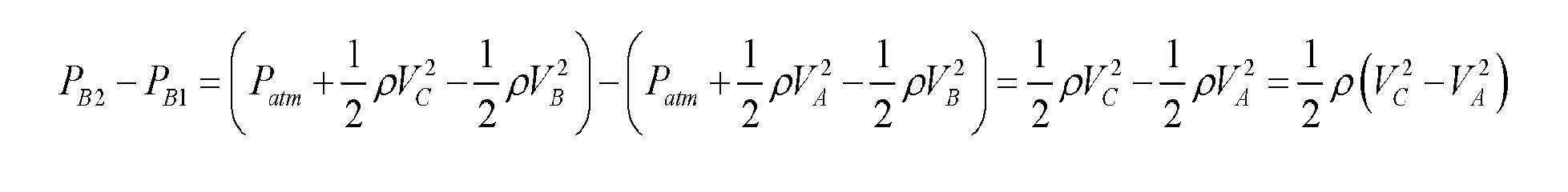
  • the pressure difference across the actuator disc follows: [0098]
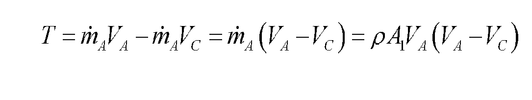
  • the thrust acting on the actuator disc is [0099]
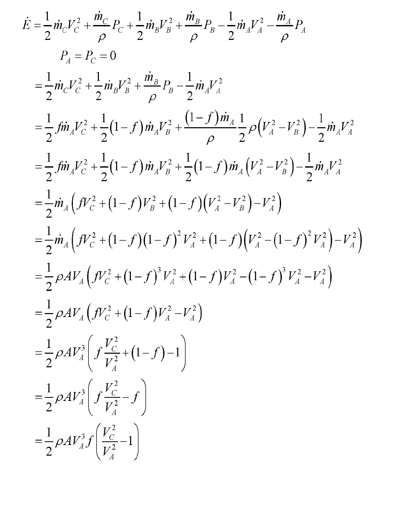
  • the rate that kinetic energy is imparted to the flowing fluid follows: [00100] It is desirable to have the maximum amount of thrust per unit of kinetic power, which is determined by the following metric: [00101]
  • a conventional propeller having linearly oriented inlet flow and outlet flow would have a thrust per unit of kinetic power factor of 2.
  • Figure 2 illustrates another example Actuator Disc Theory model involving multiple actuator discs 200 that flows the fluid through a duct 202 having a 90-degree radial bend according to one embodiment of the present disclosure.
  • the area at the inlet and outlet are variable and can be specified by the design engineer. In this case, the total area of the inlet and outlet are specified so that the relationship between V B and V C is the same as the propeller, which allows the impact of the directional change to be determined.
  • This velocity ratio is obtained by specifying the area of the inlet and outlet as follows: [00104]
  • the pressure at the inlet to the actuator discs can be obtained by applying the Bernoulli equation [00105]
  • the pressure at the outlet of the actuator discs is determined by applying the Bernoulli equation to the outlet stream.
  • the net thrust on the duct results from the pressure difference on the duct area A C plus the momentum of the mass leaving the duct.
  • the rate that kinetic energy is imparted to the flowing fluid follows: [00108]
  • the thrust per unit of kinetic power follows: [00109]
  • actuator discs 200 configured in a duct 202 having a 90-degree bend in its inlet flow would have a thrust per unit of kinetic power factor of 2.75.
  • Figure 3 illustrates another example Actuator Disc Theory model involving multiple actuator discs 300 that flow the fluid through a duct 302 having a 180-degree radial bend according to one embodiment of the present disclosure.
  • the total area of the inlet and outlet are specified so that the relationship between V B and V C is the same as the actuator discs 300 (e.g., propellers), which allows the impact of the directional change to be determined.
  • actuator discs 300 configured in a duct 302 having a 180-degree bend in its inlet flow would have a thrust per unit of kinetic power factor of 2.5.
  • the actuator discs 300 configured in a duct 302 having a 180-bend is better than a conventional propeller design (e.g., 2.5 > 2.0) as described above with reference to Figure 1, but not as good as actuator discs 200 configured in a duct 202 having a 90-degree bend as described above with reference to Figure 2 (e.g., 2.5 ⁇ 2.75).
  • V B V C
  • This velocity ratio is obtained by specifying the area of the inlet and outlet as follows: [00119] Applying the Bernoulli equation at the inlet allows the suction pressure ⁇ P to be calculated [00120] The net thrust on the duct results from the pressure difference on the inlet duct plus the momentum of the mass entering and leaving the duct.
  • This particular case is an improvement over the conventional propeller design (2.0) as described above with reference to Figure 1, and the case where the actuator discs 200 are configured in a duct 202 having a 90-degree bend as described above with reference to Figure 2 (2.5).
  • Figure 5 illustrates another example Actuator Disc Theory model involving an actuator disc 500 that increases the pressure in a duct 502 having a 180-degree radial bend, while having a varied fan position according to one embodiment of the present disclosure.
  • This velocity ratio is obtained by specifying the area of the inlet and outlet as follows: [00126] Applying the Bernoulli equation at the inlet allows the suction pressure ⁇ P to be calculated [00127] The net thrust on the duct results from the pressure difference on the duct and fan, plus the momentum of the mass entering and leaving the duct.
  • FIGS. 6A, 6B, and 6C illustrate two-dimensional (x, y) flow fields determined by computational fluid dynamics (CFD) analysis for a simulated circular 180-degree duct according to one embodiment of the present disclosure.
  • CFD computational fluid dynamics
  • the width of the simulated duct inlet in Figure 6A is 1.0 meter
  • the width of the simulated duct inlet in Figure 6B is 0.75 meters
  • the width of the simulated duct inlet in Figure 6C is 0.5 meters.
  • the pressure difference that induces the flow is 1000 Pa.
  • Table 1 reports the upward thrust (N) per meter of depth in the z direction.
  • Table 1 [00131] As shown, the CFD results confirm that decreasing the inlet area relative to the outlet area increases thrust.
  • Figure 7 shows the two-dimensional (x, y) flow fields determined by computational fluid dynamics (CFD) analysis for a simulated low-profile 180-degree duct.
  • CFD computational fluid dynamics
  • FIG. 9a, 9b, 10a, and 10b show the flow fields and pressure fields, respectively, for circular and low-profile ducts in open space. More particularly, Figure 9a shows the flow field and Figure 9b show the pressure field for a circular 180-degree duct in an open space.
  • Figure 10a shows the flow field and Figure 10b shows the pressure field for a low- profile 180-degree duct in an open space.
  • the z direction emanates perpendicularly from the xy- plane.
  • Table 3 summarizes the data gathered from the CFD analysis. In both cases, the thrust per kinetic power is very similar; however, it should be emphasized that meaningful comparison is only possible at the same duct size and pressure difference. Table 3
  • FIGS 11a and 11b illustrate cross-sectional views of example propulsion systems 1100, 1102 incorporating linear circular ducting according to one embodiment of the present disclosure.
  • Each propulsion system 1100, 1102 includes a duct 1104, 1106 having an inlet portion 1108, 1110 and outlet portion 1112, 1114 with a fluid flow generator, such as one or more propellers 1120 configured inside. While a propeller is shown in this configuration, other fluid flow generators may be show in other configurations including, but not limited to, squirrel-cage fans, turbo fans, impellers, jet engines, propellers, and the like.
  • Figure 11a shows the inlet portion 1108 and outlet portion 1112 having equally sized cross-sectional areas
  • Figure 11b shows the inlet portion 1110 and outlet portion 1114 with unequally sized cross-sectional areas.
  • Figures 12a and 12b illustrate example fan arrangements (e.g., fluid flow generators) that that may be used to blow air through the duct 1104, 1106 of Figures 11a and 11b according to embodiments of the present disclosure.
  • axial fans are shown here, it is possible to use any suitable type of fluid flow generator, such as squirrel-cage fans, turbo fans, impellers, jet engines, propellers, and the like.
  • FIG. 12a shows multiple fans with unequally sized areas
  • FIG. 12b shows fans with equally sized areas.
  • Figures 13a and 13b illustrate an example flying car 1300 according to one embodiment of the present disclosure.
  • the flying car 1300 employs equal-area circular ducts similar to that shown and described above with reference to Figure 11a.
  • the ducts 1302 are selectively movable from a deployed position (flying mode) in which the ducts 1302 are fully extended as shown in Figure 13a to a retracted position (driving mode) as shown in Figure 13b.
  • the flying car 1300 includes a passenger compartment 1304 that may be used to seat a user, such as a driver of the flying car 1300. Although the passenger compartment 1304 is shown as an open cockpit, other embodiments contemplate that the passenger compartment can be covered to allow the passenger to fly in a closed cockpit. [00138] In one embodiment, the flying car 1300 includes an upper section 1306 and a lower section 1308.
  • Figures 14a and 14b illustrate cross-sectional views of example propulsion devices 1400, 1402 incorporating linear low-profile ducting according to one embodiment of the present disclosure.
  • Figure 14a shows the inlets 1404 and outlet 1406 to the ducts with equally sized cross-sectional areas
  • Figure 14b shows the inlets 1408 and outlet 1410 to the ducts with unequally sized cross-sectional areas.
  • the duct may include one or more bulbs 1412 to assist the fluid turn the tight corner, and/or a scoop mechanism 1414 to help fluid enter with less loss.
  • a variety of different fluid flow generators such as propellers (or other devices) may be utilized.
  • Figures 15a and 15b illustrate example vertical-lift flying motorcycles 1500, 1502 with low-profile ducts with unequally sized inlet and outlet areas according to one embodiment of the present disclosure.
  • the flying motorcycle 1500 of Figure 15a shows a ducting arrangement in which the passenger faces parallel to the ducts of the flying motorcycle
  • the flying motorcycle 1502 of Figure 15b shows a ducting arrangement in which the passenger faces perpendicular to the ducts of the flying motorcycle.
  • Design example [00141] Perpendicular orientation, low-profile duct – Table 3 shows the CFD data for the ducts in free space.
  • the low-profile duct has a width of 2.6 m.
  • two adjacent ducts have a width of 5.2 m, which are oriented as shown in Figure 15b.
  • the circular duct has a width of 2.6 m.
  • two adjacent ducts When placed side-by-side, two adjacent ducts have a width of 5.2 m, which are oriented as shown in Figure 15b.
  • a 65-hp Rotax Type 582 engine can power the lighter aircraft [00164] At an output power of 20 kW, the specific fuel consumption is 590 g/kWh (see Figure 16a); therefore, the fuel consumption rate is [00165]
  • a 100-hp Rotax Type 912 engine can power the heavier aircraft [00166] At an output power of 70 kW, the fuel consumption rate is 24 L/h (see Figure 16b). The density of fuel is about 0.77 kg/L, so the fuel consumption rate is 18.5 kg/h.
  • Duct options [00167] Figures 17 through 22 show various optional arrangements for the duct of the propulsion device, which address various means to improve efficiency or lift according to one or more embodiments of the present disclosure.
  • Figure 17 illustrates one embodiment of a propulsion device 1700 having a duct 1702 with a long, straight outlet portion 1704.
  • Figure 18 illustrates another embodiment of a propulsion device 1800 having a duct 1802 with a long, straight profile. Additionally included are external turning vanes 1804 that help improve efficiency.
  • Figure 19 illustrates another embodiment of a propulsion device 1900 having duct 1902 a short, straight profile. Additionally included are external turning vanes 1904 that help improve efficiency.
  • Figure 20 illustrates another embodiment of a propulsion device 2000 having a duct 2002 with an extra-long, straight outlet portion 2004.
  • Figure 21 illustrates another embodiment of a propulsion device 2100 having a duct 2102 with an extra-long, straight outlet portion 2104.
  • FIG. 22 illustrates another embodiment of a propulsion device 2200 having a duct 2202 with an extra-long, straight outlet portion 2204. Additionally included are diverging vanes 2206 configured at the bottom end of the outlet portion to provide enhanced efficiency.
  • Squirrel cage fans [00170]
  • Figures 23 through 25 illustrate another example propulsion system utilizing squirrel cages assemblies 2300, 2400 that may be implemented on a flying car 2500 according to embodiments of the present disclosure.
  • the propulsion system 2300 includes a duct 2306 having an inlet portion 2304 and outlet portion 2308 that are configured on a flying car 2500.
  • Figures 24a and 24b show cones 2420 in the center of the squirrel cage propeller.
  • FIG 25a shows the flying car 2500 with the inlet portion 2304 of the duct 2410 removed in order to reveal the inlet 2304 of the propeller
  • Figure 25b shows the inlet portion 2402 of the duct 2410 in operative engagement on the flying car 2500.
  • Figure 23 illustrates an example squirrel cage propeller assembly 2300 that may be implemented with the propulsion system according to one embodiment of the present disclosure.
  • the squirrel cage assembly 2300 includes two pair of squirrel cage propellers 2302, each having an inlet 2304 that receives fluid from the inlet portion of the duct 2306 to generate an outlet stream for providing lift for the flying car 2500 of Figures 25a and 25b.
  • each pair of squirrel cage propellers 2302 is configured to turn in opposite directions to balance angular momentum.
  • one or both pair of propellers are driven by a single motor located proximate the center of the flying car 2500.
  • a bulb 2312 helps direct the flow out of the squirrel cage.
  • FIG 24a and 24b illustrate an example squirrel cage propeller 2400 that may be implemented with the flying car 2500 according to one embodiment of the present disclosure.
  • the squirrel cage assembly 2400 has an inlet 2402 that receives fluid from the inlet portion of the duct 2410 to generate an outlet stream for providing lift for the flying car 2500.
  • Figure 24a shows the assembly 2400 with the inlet portion 2410 of the duct 2306 removed, whereas Figure 24b shows the inlet portion 2410 of the duct 2306 in operative engagement on the assembly 2400.
  • An optional cone 2420 helps direct inlet flow in the radial direction.
  • two vertical gyroscopes (not shown), each rotating in opposite directions may be provided. These gyroscopes stabilize the flying vehicle from gusts of wind. Also, if one gyroscope spins slightly faster than the other, the flying car can rotate and adjust yaw.
  • horizontal thrust can be obtained by tilting the vehicle so that a portion of the lifting thrust becomes horizontal thrust.
  • Figure 25a illustrates an external view of the flying car with no inlet ducts 2410 whereas Figure 25b illustrates an external view of a flying car with inlet ducts 2410.
  • Circular Ducts [00176]
  • Figures 26a, 26b, and 26c illustrates example various propeller types that may be implemented with a circular duct according to embodiments of the present disclosure.
  • Figure 26a shows a ducted axial propeller 2604
  • Figure 26b shows a squirrel-cage propeller 2606
  • Figure 26c shows a turbo propeller 2608.
  • Figure 27 shows an example turbo propeller as shown and described with reference to Figure 26c.
  • the “turning duct” produces thrust as the flow reverses.
  • the propellers can be nested in some embodiments.
  • Figure 28 illustrates multiple clustered circular ducts that combine their thrust to increase lift capability. By rotating half the fans clockwise and the other half counter-clockwise, net torque on the aircraft may be reduced or eliminated.
  • Coanda Effect [00178]
  • Figure 29 illustrates an example hybrid lifting system that employs the Coanda Effect to provide additional lift. As shown, the duct includes multiple, nested vanes that direct outlet stream generated by the propeller through a directional turn.
  • FIGs 30 through 32 illustrate example jet engines 3000, 3100, and 3200 that may be implemented with the propulsion system according to embodiments of the present disclosure.
  • Figure 30 illustrates a schematic diagram of a conventional axial jet engine, so named because most or all the fluids flow generally in an axial direction.
  • the jet engine 3000 would be immersed in air (e.g., airplane) or water (e.g., ship).
  • FIG. 31 illustrates a schematic of a radial jet engine 3100, so named because the inlet fluid has a radial component to its velocity. Fluid enters along the circumferential opening with area A 1 and exits from the axial opening with area A 2. A conical plate redirects the radial flow into the axial direction resulting in axial thrust acting on the conical plate.
  • Figure 32 illustrates a reverse-flow jet engine 3200. Flow enters from the bottom and encounters a thrust plate that reverses the flow through a 180-degree duct. As shown previously, when fluid enters through a 180-degree duct, thrust is greater than a conventional propeller.
  • WATER VEHICLES Torpedo [00182] Figures 33 through 38 illustrate example torpedoes that may be implemented with the propulsion system according to embodiments of the present disclosure. In particular, Figure 33 shows the flow around a conventional torpedo whereas Figures 34a through 34d show various options for torpedoes with axial propellers.
  • Figure 34a describes two counter-rotating propellers, which are often used in torpedoes.
  • Figure 34b describes a single rotating propeller with a stationary stator to remove the rotation from the exiting fluid. Both Figures 34a and 34b employ a shallow-angle inlet cone leading to the propeller.
  • Figures 34c and 34d are comparable to Figures 34a and 34b, except that a steep-angle inlet cone leads to the propeller, which shortens the length of the torpedo.
  • an undesirable feature of this approach is that there may be flow separation between the fluid and the inlet cone. In torpedoes, a shallow angle is employed to prevent flow separation, which would increase form drag.
  • Figures 35a through 35e illustrate several embodiments of squirrel-cage propellers that may be used with a torpedo according to embodiments of the present disclosure.
  • Figure 35a shows a single squirrel-cage propeller
  • Figure 35b shows a double squirrel-cage propeller with counter rotation
  • Figure 35c shows a single squirrel-cage propeller with a stationary stator to remove rotation from the exiting fluid
  • Figure 35d shows the blade design for a counter- clockwise rotation
  • Figure 35e shows the blade design for a clockwise rotation.
  • Figures 36a through 36ed illustrate other embodiments of the squirrel-cage propeller, which are similar to the embodiments of Figures 35a through 35e, except that turning vanes are employed.
  • Figure 37a through 37e illustrate other embodiments of the squirrel-cage propeller, which are similar to the embodiments of Figures 36a through 36e except that a reduction nozzle is employed at the outlet. This embodiment would be used if the propeller diameter were small, but high thrust is required. Because of the nozzle, the interior pressure of the squirrel-cage propeller is large, which applies a large force to the interior cone of the propeller and thereby produces a large thrust.
  • Figures 38a and 38b are cut-away views showing the interior and exterior cone of a turbo propeller.
  • Figure 38a does not include a stator.
  • Figure 38b includes a stator to remove rotation from the fluid exiting the propeller.
  • FIG 39 illustrates a jet boat 3900 in which the propeller 3902 (e.g., a ducted axial propeller) is located in the interior of the boat.
  • the inlet water feeding the interior propeller comes from opposite sides of the boat; therefore, the inlet momentum is canceled.
  • forward thrust is imparted.
  • Additional forward thrust is imparted from the momentum of the fluid ejected from the rear of the boat.
  • SWATH Small Waterplane Area Twin Hull
  • Figures 40a and 40b illustrate various bottom and frontal views of a traditional monohull boat hull, a catamaran boat hull, and a Small Waterplane Area Twin Hull (SWATH) hull.
  • FIG. 40b shows an artist’s concept for a SWATH employing a steep-angle inlet cone ducted axial propeller. Alternatively, the squirrel-cage propeller or turbo propeller could be used.
  • Figure 41 shows the submerged portion of SWATH boat.
  • Figure 41a shows the circular cross section, as illustrated in Figure 40b.
  • Figure 41b shows a semi-circular cross section, which is open on the bottom and filled with air.
  • Figures 41c and 41d show an option for reducing viscous drag. A porous membrane surrounds the hull.
  • the membrane could be a variety of materials; however, Teflon is envisioned because of its low surface energy, which will reduce adhesion of fouling materials.
  • the membrane could be made from expanded Teflon (i.e., Gore Tex), woven Teflon fibers, non-woven Teflon fibers, Teflon felt, or sintered Teflon particles.
  • the membrane could be sintered metal.
  • the sintered metal could be coated with Teflon or electroless nickel/Teflon. Compressed air is forced between the membrane and the solid surface so that small bubbles of air are trapped in the membrane pores. Primarily, the water interfaces with air rather than a solid surface, which reduces friction.
  • FIGS 42a and 42b illustrate bottom and side views, respectively, of a monohull boat in “travel mode” meaning it is traveling with a significant forward velocity.
  • Figure 43a and 43b illustrate bottom and side views, respectively, showing another monohull boat in “thrust mode” meaning it is traveling with a nearly zero velocity, but has tremendous thrust.
  • thrust mode would be useful for icebreakers. While in thrust mode, because of the 180-degree bend, the boat will produce significantly more thrust than a conventional propeller.
  • Thrust mode is achieved by placing the turning duct just forward of the radial jet engine. While in travel mode, the turning ducts could be removed and stored elsewhere on the boat.
  • FIG. 44 is a schematic diagram illustrating an example jet pack 4400 according to one embodiment of the present disclosure.
  • the jet pack 4400 generally includes two engines, each having two nested jet ejectors 4412a, 4412b that are powered by high-pressure propellant fuel stored a storage tank 4404. Two valves 4406 are provided that independently control the flow of fuel to nozzles 4414 configured on each engine.
  • high-pressure propellant fuel delivered to each engine is provided by catalyst beds 4408 that decomposes the propellant fuel from the storage tank 4404 to produce high-velocity gases .
  • the storage tank 4404 may store the propellant fuel at high pressure (as shown), or alternatively, the storage tank 4404 may store the propellant fuel at a relatively low pressure in which the propellant fuel is delivered to the catalyst bed 4408 via a pump (not shown).
  • the propellant fuel used by jet packs is high-concentration ( ⁇ 90%) hydrogen peroxide dissolved in water.
  • the following reaction occurs: 2 H 2 O 2 ® 2 H 2 O + O 2
  • a catalyst bed e.g., silver, manganese dioxide
  • the reaction is exothermic so the product water is steam.
  • the energy density of the propellant fuel mixture can be increased by adding a reducing component, such as alcohol, sugar, or a hydrocarbon.
  • counter-rotating flywheels 4416 can be located on the jet pack 4400 to enhance stability. Furthermore, if the rotation rate of one flywheel 4416 is greater than the other, it allows the jet pack to rotate about the vertical z-axis, thus providing an element of control. In another embodiment, two pairs of counter-rotating flywheels can be oriented with the rotation axes at right angles with respect to each other, thus allowing stable control in both the x-axis and z-axis.
  • FIG. 45 illustrates a schematic diagram of another example jet pack 4500 according to one embodiment of the present disclosure.
  • the jet pack 4500 is similar in design and construction to the jet pack 4400 shown and described above with reference to Figure 44, except that electricity-powered ducted fans 4502 replace the ejectors 4412a, rocket nozzle 4414 combination.
  • a hollow annulus may be configured in the jet ejector 4412b to store batteries.
  • Figure 46 illustrates a schematic diagram of another example jet pack 4600 according to one embodiment of the present disclosure.
  • FIG. 47 illustrates a top view of an example jet ejector 4700 according to one embodiment of the present disclosure.
  • the jet ejector 4700 includes opposing ducts 4702 that are disposed on both sides of four engines 4704 that are arranged in a linear fashion relative to one another.
  • each engine 4704 may include an engine 4402, 4502, 4602, such as described above with reference to Figures 44, 45, and 46.
  • the engines 4704 are configured to receive a fluid (e.g., air) to generate an inlet fluid flow through an inlet portion 4706 of the duct 4702 and generate an outlet fluid flow through an outlet portion of the duct 4702, which in this particular example, would be downward beneath the engines 4704.
  • the inlet portion 4706 is bent in a circular shape to alter a direction of a corresponding either one of the input stream or the output stream generated by the engines 4704.
  • Figure 48 illustrates a top view of a linear jet ejector assembly 4800 according to one embodiment of the present disclosure.
  • the linear jet ejector assembly 4800 generally includes three jet ejectors 4700 arranged as shown.
  • a passenger 4802 is shown in operative position with regard to the jet ejector assembly 4800 such that, when thrust is applied by the assembly 4800, the passenger 4802 may be lifted from the ground.
  • Figure 49 is a schematic diagram of an example jet pack 4900 according to one embodiment of the present disclosure.
  • the jet pack 4900 includes an electricity-powered blower 4902 that provides pressurized air to a combustor 4904. Fuel is added to the combustor 4904 from a pressurized fuel tank 4906. In other embodiments, a pump could provide fuel from an atmospheric-pressure tank (not shown).
  • FIGs 50a and 50b illustrate an example jet ejector 5000a, 5000b according to one embodiment of the present disclosure.
  • the jet ejector 5000a of Figure 50a includes a duct with an inlet portion that is bent at a 180-degree angle
  • the jet ejector 5000b of Figure 50b includes a duct with an inlet portion that is bent at a 90-degree angle.
  • the jet ejector 5000 includes an electricity-powered blower 5002 that pressurizes a reservoir 5004 denoted by the gray-shaded area.
  • the pressurized air flows through a nozzle that induces air flow through a jet ejector 5008 with turning vanes 5010. The change in flow direction from the turning vanes enhances lift.
  • a hollow region inside the ejector 5008 may be used to hold batteries.
  • the geometry of the jet ejector 5008 can be circular or linear.
  • the inlet portion 5012 of the turning vanes can be greater than or less than the outlet area from the jet ejector 5008.
  • the blower 5002 can be any desired type (e.g., axial, centrifugal, or squirrel cage).
  • the compressor inlet can be configured with a muffler 5020 in some embodiments.
  • the reservoir 5004 can be heated by burning a fuel, which increases the velocity through the nozzle and thereby reduces the required power input from the blower.
  • FIGS 51a and 51b illustrate other example jet packs 5100a, 5100b according to one embodiment of the present disclosure.
  • the jet pack 5100a, 5100b are similar to the jet packs 5000a, 5000b of Figures 50a and 50b, except that the exhaust from a jet engine 5102 pressurizes the reservoir 5104. Additionally, a hollow cavity in the jet ejectors 5106 can be used to house the fuel.
  • the air exiting the nozzle is blended with turning-vane air in stages, which minimizes velocity differences upon mixing and thereby improving efficiency.
  • FIGs 52a and 52b illustrate other example jet packs 5200a, 5200b according to one embodiment of the present disclosure.
  • the jet packs 5200a, 5200b are similar to jet packs 5100a, 5100b, except that a rocket 5202 is implemented to induce flow through the jet ejector 5204.
  • the air exiting the nozzle is blended with turning-vane air in stages, which minimizes velocity differences upon mixing and thereby improves efficiency. That is, the end of each vane is configured at different positions along the duct so that air exiting each vane may be introduced at different positions in the duct. Additionally, a hollow region configured in the ejector 5204 may be used to hold the rocket propellant.
  • Figure 53 shows the jet packs illustrated in Figures 50a, 50b, 51a, 51b, 52a, and 52b mounted to the back of a passenger 5302.
  • Figures 54a and 54b illustrate a front view and a side view, respectively, of an example lift platform 5400 according to one embodiment of the present disclosure.
  • the lift platform 5400 includes one or more gas-moving devices 5402 (e.g., electricity-powered fan, jet engine, propeller, rocket), a duct inlet 5404, and a duct outlet 5406.
  • the air is drawn in from the bottom, which gives additional lift when the air turns direction.
  • the duct inlet 5404 may include a muffler to reduce noise.
  • FIG. 55a and 55b illustrates other example lift platforms 5500a, 5500b according to one embodiment of the present disclosure.
  • the lift platform 5500 includes a single-propeller 5502 for providing lift.
  • a gyroscope 5504 is included, which rotates opposite the propeller to prevent the platform from rotating due to torque imparted by the propeller 5502. If a passenger 5506 wishes to rotate the platform about its vertical axis, he or she can cause the gyroscope 5504 to rotate slightly faster or slower.
  • the lift platform can be implemented in a circular or linear geometry.
  • FIGs 56a and 56b illustrates other lift platforms 5600a, 5600b according to one embodiment of the present disclosure.
  • Each lift platform 5600a, 5600b includes a double-propeller assembly including two propellers 5602, 5604.
  • Each propeller 5602, 5604 rotates in an opposite direction to prevent the platform from rotating. If a passenger 5606 wishes to rotate the platform about the vertical axis, he or she can rotate one propeller slightly faster and the other slightly slower. The platform will rotate in the direction opposite of the faster propeller.
  • the lift platform can be implemented in a circular or linear geometry.
  • Figure 57 shows an example measured value of drag on a ship hull as a function of speed.
  • Figure 58 shows the flow streams around a ship hull.
  • the turbulent eddies behind the ship are responsible for about 3 to 5% of the total drag (see Table 4 and Figure 59).
  • Table 4 [00222]
  • the dominant residual drag is caused by the generation of waves ( Figures 60 and 61).
  • the impact of waves is minor at low speeds and becomes dominant at high speeds. Depending upon the length of the ship and its speed, the waves have particular resonances that can impact drag significantly.
  • Figure 62 shows an example hydrodynamic pressure acting on a boat hull.
  • FIG. 63 illustrates a conventional propeller model according to one embodiment of the present disclosure. According the Actuator Disc Theory, the velocity V B at the actuator disc is the arithmetic average of upstream velocity V A and the downstream velocity V C .
  • Mass continuity allows the relationship between the areas to be calculated [00227]
  • the energy content (J/m 3 ) contains a pressure component (N/m 2 or J/m 3 ) and a kinetic energy component (J/m 3 ), as determined by the Bernoulli equation.
  • the Bernoulli equation is applied to the fluid upstream of the actuator disc: [00228]
  • the Bernoulli equation can also be applied to the fluid downstream of the actuator disc: [00229]
  • the pressure difference across the actuator disc follows: [00230]
  • the thrust is [00231]
  • the rate that kinetic energy is imparted to the flowing fluid follows: [00232] It is desirable to have the maximum amount of thrust per unit of kinetic power, which is determined by the following metric: [00233]
  • the efficiency is
  • Figure 67 shows the efficiency of a variable-pitch two-blade propeller that extends the range of efficient velocities. At its peak, the efficiency can be as high as 0.87; however, at low velocities, the efficiencies are low (about 0.60).
  • Figure 68 shows the efficiency of a variable-pitch four-blade propeller ranges from 0.49 to 0.77.
  • FIG. 69a illustrates an example maritime propulsion system 6900 that is mounted on a ship 6902 according to one embodiment of the present disclosure.
  • the maritime propulsion system 6900 includes a duct 6906 that provides a technique for increasing a propulsive area created by a driving force, such as a propeller 6904.
  • the duct 6906 may be configured on the ship 6902 in any suitable manner.
  • a bank of axial or screw propellers 6904 located on the front of the duct 6906 draws water from the underside of the ship and ejects it from the rear, thus providing thrust.
  • the cross sectional size of the submerged duct 6906 can be approximately similar to, less than, or greater than the cross sectional size of the submerged portion of the hull.
  • Figures 69b and 69c show an embodiment that has a pivoting extended flap 6908. Depending on the weight of cargo in a ship, the draft of the ship can vary dramatically. The angle of the pivoting extended flap can vary to ensure the fluid discharge is always below the water line.
  • Figure 69d shows an embodiment in which the propulsor 6905 draws fluid from the underside of the duct.
  • FIG. 70 illustrates another example maritime propulsion system 7000 according to one embodiment of the present disclosure.
  • the maritime propulsion system 7000 includes a structure 7002 configured with a hole for placement of a disc actuator (propeller) 7004 inside.
  • the structure 7002 may be envisioned as a stationary dock, or the symmetrical portion of a ship or aircraft.
  • the disc actuator 7004 draws fluid (water) from the adjacent free stream beside the structure 7002.
  • this analysis is performed in the context of a maritime propulsion system, it may be applied to aircraft propulsion as well.
  • Figure 71 illustrates a schematic representation of a maritime propulsion system 7100 according to one embodiment of the present disclosure.
  • the propulsion system 7100 described in Figure 70 is configured at the stern of a ship 7102.
  • a duct 7108 is placed at the stern 7106 of the ship 7102 that has essentially the same cross section as the submerged section of the hull.
  • Fluid is drawn from the sides and possibly bottom by one or more disc actuators (propellers) 7110, which fills the duct and pushes fluid towards the rear.
  • the duct 7108 can have inlet turning vanes (not shown) that help change the fluid direction efficiently.
  • the advantages of this technology include, but are not necessarily limited to the following ⁇
  • the size of the propeller device is decoupled from the size of the propulsion cross section, thus providing added design flexibility.
  • multiple small-diameter propellers could line the wall of the duct and thereby replace one large propeller.
  • multiple small rudders can be incorporated into the duct, which allows for vectored thrust and enhanced maneuverability.
  • the type of propeller may include not only traditional axial propellers, but also centrifugal and squirrel cage propellers among others (see Figure 73).
  • the entrance is rounded to provide a smooth flow path.
  • the center of the squirrel cage can contain a central cone that ensures the velocity is approximately constant along the axis.
  • the squirrel cage propeller can incorporate stationary stators that convert rotational kinetic energy into translational kinetic energy, thus improving efficiency. Furthermore, the stators can be actuated giving the ability to change the angle relative to the rotating hydrofoils of the squirrel cage propeller, thus allowing high efficiency at a variety of rotational speeds.
  • Inlet guide vanes regulate the angle of attack of the fluid relative to the rotating hydrofoils of the squirrel cage propeller. Similarly, the inlet guide vanes can be rotated to change the angle of attack, thus allowing high efficiency at a variety of rotational speeds.
  • Both the stators and guide vanes can be segmented along the axial length of the squirrel cage.
  • each segment can be individually rotated for optimal angles both along the axis and the circumference.
  • the optimal position of each segment can be adjusted to reduce energy consumption for each condition (e.g., speed, water density, water viscosity).
  • Traditional propellers have a cross-sectional area only a fraction – typically 10 to 50% – of the submerged cross-sectional area of the hull.
  • the duct fills the entire cross section, which has the following benefits: o The wake eddies behind the boat are eliminated, which reduces drag by about 3 to 5%.
  • FIG. 75a shows a reversing duct that slides vertically downward to reverse flow.
  • Figure 75b shows a reversing duct that pivots to reverse flow.
  • Figure 75c shows a reversing duct with two pivot points. One rotates the entire duct into position and the other rotates nested duct segments into a fully deployed position.
  • Figure 76 illustrates another example ducted propulsion system according to one embodiment of the present disclosure. Although this analysis is performed in the context of a maritime propulsion system, it may be applied to aircraft propulsion as well. [00257] Define f [00258] Account for mass [00259] Account for y momentum [00260] Substituting [00261] The power is [00262] The thrust-to-power ratio is [00263] Flip sign so thrust is in forward direction [00264] This is the same as a conventional propeller. [00265] The efficiency is [00266] The propulsive efficiency approaches 1.0 as V A /V C approaches 1.0.
  • Figure 77 illustrates another example ducted propulsion system 7900 according to one embodiment of the present disclosure.
  • This analysis is performed in the context of a maritime propulsion system, it may be applied to aircraft propulsion as well.
  • the power is [00278]
  • the thrust-to-power ratio is [00279] Flip sign so thrust is in forward direction [00280]
  • the efficiency is
  • Figures 78 and 79 show the propulsive efficiency and factor in the square bracket, respectively. [00282] It should be emphasized that these equations may only be valid to the degree that the boundary conditions can be achieved.
  • Option 4 [00283]
  • Figure 80 illustrates another example ducted propulsion system 8000 according to one embodiment of the present disclosure. Although this analysis is performed in the context of a maritime propulsion system, it may be applied to aircraft propulsion as well. The ducted propulsion system 8000 is similar to the ducted propulsion system of Figure 77, except areas A 1 and A 2 are not identical.
  • the thrust-to-power ratio is [00293] Flip sign so thrust is in forward direction [00294]
  • the efficiency is [00295]
  • Figures 81 and 82 show the propulsive efficiency and factor in the square bracket, respectively of the propulsion system 7800 described above.
  • Figure 84 illustrates an example hardware implementation 8400 of the ducted propulsion system of Figure 77.
  • the hardware implementation 8400 includes a squirrel cage fluid mover 8402 having a squirrel cage 8404 concentrically aligned with stators 8406 that remove spin from the fluid.
  • Turning vanes 8410 direct the radial flow toward the rear.
  • the angle of attack of the hydrodynamic foils can be varied using a mechanical pivot mechanism in some embodiments.
  • Figure 85 illustrates an example hardware implementation of the maritime propulsion system 8000 according to one embodiment of the present disclosure.
  • the system 8000 is configured at the rear of a ship 8002. A portion of the fluid flows through a propeller 8004 and is directed rearward.
  • the propeller 8004 can be a squirrel cage ( Figure 84) or a centrifugal pump (Figure 86). At its optimal operating condition, a centrifugal pump is about 85% efficient ( Figure 87). Variable-angle inlet guide vanes can extend the efficiency over a wider operating range. Furthermore, during operation, the area ratio (A 1 /A 2 ) can be adjusted to maintain optimal performance at a variety of ship velocities.
  • Aircraft [00300] It should be emphasized that although these ducted propulsion systems have have been described in the context of ship propulsion, the concepts can be applied equally well to aircraft. For example, the propulsion system illustrated in Figure 84 could be mounted on a conventional aircraft and has the advantage that it is not affected by bird strikes.
  • Figure 88 shows the temperature, pressure, and velocity at various points in a turbojet engine.
  • the inlet velocity V A is 450 ft/s (307 mi/h) and the outlet velocity V C is 1600 ft/s (1090 mi/h).
  • the propulsive efficiency is [00302]
  • Figure 89 shows the propulsive efficiency for aircraft engines as a function of airspeed. (Note: The data point in the figure is the above calculated efficiency for a turbojet.) In the range of typical commercial aircraft (460 to 575 miles per hour), the propulsive efficiency of high bypass turbofan engines is 74–83%; therefore, efficiency gains are possible by increasing the area through which air flows.
  • Figures 90 and 91 show embodiments where the propulsion system 9000, 9100 is placed behind the fuselage 9002, 9102 of an aircraft 9004, 9104.
  • Figure 90 shows axial fans 9006 on the faces of the duct
  • Figure 91 shows squirrel cage fans 9106 (see Figure 73a).

Landscapes

  • Engineering & Computer Science (AREA)
  • Aviation & Aerospace Engineering (AREA)
  • Mechanical Engineering (AREA)
  • Chemical & Material Sciences (AREA)
  • Combustion & Propulsion (AREA)
  • Ocean & Marine Engineering (AREA)
  • General Engineering & Computer Science (AREA)
  • Transportation (AREA)
  • Physics & Mathematics (AREA)
  • Fluid Mechanics (AREA)
  • Structures Of Non-Positive Displacement Pumps (AREA)

Abstract

A propulsion system includes a duct and a fluid flow generator. The duct has an elongated cavity with an inlet portion and an outlet portion. The fluid flow generator is disposed in the duct. The fluid flow generator configured to receive a fluid to generate an inlet stream through the inlet portion and generate an outlet stream through the outlet portion. The outlet stream is configured to generate thrust for a vehicle on which the fluid flow generator and the duct are mounted, and at least one of the inlet portion or the outlet portion is bent in a circular shape to alter a direction of a corresponding either one of the input stream or the output stream.

Description

Enhanced-Thrust Lift and Propulsion Systems CROSS REFERENCE TO RELATED APPLICATIONS [001] This application is related to and claims priority under 35 U.S.C. § 119 to U.S. Patent Application Nos. 62/962,154 filed on January 16, 2020 entitled “Enhanced-Thrust Lift and Propulsion System”; 62/888,971 filed on August 19, 2019 entitled “Jet Pack”; 62/899,715 filed on September 12, 2019 entitled “ Jet Pack”; 62/957,122 filed on January 4, 2020 entitled “Propulsion System”; and 62/962,144 filed on January 16, 2020 entitled “Propulsion System.” Each of these applications is hereby incorporated by reference in its entirety. TECHNICAL FIELD [002] Aspects of the present disclosure relate to vehicles and, in particular, to an enhanced-thrust lift and propulsion system. BACKGROUND [003] Propellers are often used to provide motive propulsion for vehicles moving through fluids, such as propellers used to propel boats over the water, or those used to propel airplanes through the air, or those used to lift helicopters into the air. The performance of propellers is often assessed using Actuator Disc Theory, which is also commonly known as Momentum Theory. In general, actuator disc theory is a mathematical model in which the propeller is modeled as an infinitely thin disc that overcomes a pressure difference across the two disc faces and induces a constant fluid velocity perpendicular to the disc faces. Based on the density, pressure, and velocity of the fluid (e.g., air, water) that flows through the actuator disc, a mathematical connection can be extracted between disc size, power, and lift (thrust). SUMMARY [004] According to one embodiment of the present disclosure, a propulsion system includes a duct and a fluid flow generator. The duct has an elongated cavity with an inlet portion and an outlet portion. The fluid flow generator is disposed in the duct. The fluid flow generator is configured to receive a fluid to generate an inlet stream through the inlet portion and generate an outlet stream through the outlet portion. The outlet stream is configured to generate thrust for a vehicle on which the fluid flow generator and the duct are mounted, and at least one of the inlet portion or the outlet portion is bent in a circular shape to alter a direction of a corresponding either one of the input stream or the output stream. BRIEF DESCRIPTION OF THE DRAWINGS [005] The various features and advantages of the technology of the present disclosure will be apparent from the following description of particular embodiments of those technologies, as illustrated in the accompanying drawings. It should be noted that the drawings are not drawn to scale; however, the emphasis instead is being placed on illustrating the principles of the technological concepts. Also, in the drawings the like reference characters refer to the same parts throughout the different views. The drawings depict only typical embodiments of the present disclosure and, therefore, are not to be considered limiting in scope. [006] Figure 1 illustrates an example Actuator Disc Theory model involving a linearly oriented input flow and outlet flow according to one embodiment of the present disclosure. [007] Figure 2 illustrates another example Actuator Disc Theory model involving multiple actuator discs that increase the pressure in a duct having a 90-degree radial bend according to one embodiment of the present disclosure. [008] Figure 3 illustrates another example Actuator Disc Theory model involving multiple actuator discs that increase the pressure in a duct having a 180-degree radial bend according to one embodiment of the present disclosure. [009] Figure 4 illustrates another example Actuator Disc Theory model involving an actuator disc that increases the pressure in a duct having a 180-degree radial bend, while having a varied fan position according to one embodiment of the present disclosure. [0010] Figure 5 illustrates another embodiment of an Actuator Disc Theory model involving an actuator disc located in a 180-degree duct according to one embodiment of the present disclosure. [0011] Figures 6A, 6B, and 6C show the two-dimensional (x, y) flow fields determined by computational fluid dynamics (CFD) analysis for a simulated circular-profile 180-degree duct. [0012] Figure 7 shows the two-dimensional (x, y) flow fields determined by computational fluid dynamics (CFD) analysis for a low-profile 180-degree duct. [0013] Figure 8 report the upward thrust (N) per meter of depth in the z direction. [0014] Figures 9a, 9b, 10a, and 10b show the flow fields and pressure fields, respectively, for circular and low-profile ducts in open space. [0015] Figures 11a and 11b illustrate cross-sectional views of example propulsion systems incorporating linear circular ducting according to one embodiment of the present disclosure. [0016] Figures 12a and 12b illustrate example fan arrangements that that may be used to blow air through the duct of Figures 11a and 11b according to embodiments of the present disclosure. [0017] Figures 13a and 13b illustrate an example flying car according to one embodiment of the present disclosure. [0018] Figure 14a and 14b illustrate cross-sectional views of example propulsion devices incorporating linear low-profile ducting according to one embodiment of the present disclosure. [0019] Figures 15a and 15b illustrate example vertical-lift flying motorcycles with low- profile ducts with unequally sized inlet and outlet areas according to one embodiment of the present disclosure. [0020] Figures 16a and 16b illustrate specific fuel consumption rates at various output powers of gas engines according to one embodiment of the present disclosure. [0021] Figure 17 illustrates one embodiment of a propulsion device having a duct with a short, straight outlet portion. [0022] Figure 18 illustrates another embodiment of a propulsion device having a duct with a long, straight outlet portion and an external turning vane at the inlet portion. [0023] Figure 19 illustrates another embodiment of a propulsion device having a duct with external turning vanes configured at the bottom end of the outlet duct portion of the duct. [0024] Figure 20 illustrates another embodiment of a propulsion device having a duct with an extra-long, straight outlet portion. [0025] Figure 21 illustrates another embodiment of a propulsion device having a duct with an extra-long, straight outlet portion and a restricted outlet. [0026] Figure 22 illustrates another embodiment of a propulsion device having a duct with an extra-long, straight outlet portion and a flared outlet. [0027] Figure 23 illustrates an example squirrel cage propeller assembly that may be implemented with the propulsion system according to one embodiment of the present disclosure. [0028] Figure 24a and 24b illustrate an example squirrel cage propeller that may be implemented with the flying car according to one embodiment of the present disclosure [0029] Figure 25a illustrates an external view of flying car with no inlet ducts. [0030] Figure 25b illustrates an external view of a flying car with inlet ducts. [0031] Figures 26a, 26b, and 26c illustrates example various propeller types that may be implemented with a circular duct according to embodiments of the present disclosure. [0032] Figure 27 illustrates an example turbo propeller as shown and described with reference to Figure 26c. [0033] Figure 28 illustrates multiple clustered circular ducts that combine their thrust to increase lift capability. [0034] Figure 29 illustrates shows an example hybrid lifting system that employs the Coanda Effect to provide additional lift. [0035] Figure 30 illustrates a schematic diagram of a conventional axial jet engine. [0036] Figure 31 illustrates a schematic of a radial jet engine. [0037] Figure 32 illustrates a reverse-flow jet engine. [0038] Figure 33 shows the flow around a conventional torpedo. [0039] Figures 34a through 34d show various options for torpedoes with axial propellers. [0040] Figures 35a through 35e illustrate several embodiments of squirrel-cage propellers that may be used with a torpedo according to embodiments of the present disclosure. [0041] Figure 36a through 36ed illustrate other embodiments of the squirrel-cage propeller, which are similar to the embodiments of Figures 35a through 35e, except that turning vanes are employed. [0042] Figure 37a through 37e illustrate other embodiments of the squirrel-cage propeller, which are similar to the embodiments of Figures 36a through 36e except that a reduction nozzle is employed at the outlet. [0043] Figures 38a and 38b are cut-away views showing the interior and exterior cone of a turbo propeller. [0044] Figure 39 illustrates a jet boat in which the propeller is located in the interior of the boat. [0045] Figure 40a and 40b illustrate various bottom and frontal views of a traditional monohull boat hull, a catamaran boat hull, and a Small Waterplane Area Twin Hull (SWATH) hull. [0046] Figures 41a to 41d show the submerged portion of SWATH boat. [0047] Figure 42a and 42b illustrate bottom and side views, respectively, of a monohull boat in “travel mode” meaning it is traveling with a significant forward velocity. [0048] Figure 43a and 43b illustrate bottom and side views, respectively, showing the monohull boat in “thrust mode” meaning it is traveling with a nearly zero velocity, but has tremendous thrust. [0049] Figure 44 is a schematic diagram illustrating an example jet pack according to one embodiment of the present disclosure. [0050] Figure 45 illustrates a schematic diagram of another example jet pack according to one embodiment of the present disclosure. [0051] Figure 46 illustrates a schematic diagram of another example jet pack according to one embodiment of the present disclosure. [0052] Figure 47 illustrates a top view of an example jet ejector according to one embodiment of the present disclosure. [0053] Figure 48 illustrates a top view of a linear jet ejector assembly according to one embodiment of the present disclosure. [0054] Figure 49 is a schematic diagram of an example jet pack according to one embodiment of the present disclosure. [0055] Figures 50a and 50b illustrate an example jet pack according to one embodiment of the present disclosure. [0056] Figures 51a and 51b illustrate other example jet packs according to one embodiment of the present disclosure. [0057] Figures 52a and 52b illustrate other example jet packs according to one embodiment of the present disclosure. [0058] Figure 53 shows the jet pack of Figures 52a and 52b mounted to the back of a passenger. [0059] Figures 54a and 54b illustrate a front view and a side view, respectively, of an example lift platform according to one embodiment of the present disclosure. [0060] Figures 55a and 55b illustrates other example lift platforms according to one embodiment of the present disclosure. [0061] Figures 56a and 56b illustrates other lift platforms according to one embodiment of the present disclosure. [0062] Figure 57 shows an example measured value of drag on a ship hull as a function of speed. [0063] Figures 58 and 59 show the flow streams around an example ship hull. [0064] Figures 60 and 61 illustrate how the dominant residual drag is caused by the generation of waves. [0065] Figure 62 shows an example hydrodynamic pressure acting on a boat hull. [0066] Figure 63 illustrates a conventional propeller model according to one embodiment of the present disclosure. [0067] Figure 64 shows how propulsive efficiency approaches 1.0 as VA/VC approaches 1.0. [0068] Figure 65 shows that the efficiency of a conventional propeller increases with size, although the efficiency is relatively low. [0069] Figure 66 shows propeller efficiency as a function of velocity and propeller pitch. Pitch is the distance a propeller would travel in a soft material using a single rotation. [0070] Figure 67 shows the efficiency of a variable-pitch two-blade propeller that extends the range of efficient velocities. [0071] Figure 68 shows the efficiency of a variable-pitch four-blade propeller ranges from 0.49 to 0.77. [0072] Figures 69a to 69b illustrate example maritime propulsion systems that are mounted on a ship according to various embodiments of the present disclosure. [0073] Figure 70 illustrates another example propulsion system according to one embodiment of the present disclosure. [0074] Figure 71 illustrates a schematic representation of another maritime propulsion system according to one embodiment of the present disclosure. [0075] Figure 72 illustrates multiple example rudders that can be incorporated into the duct to allow for vectored thrust and enhanced maneuverability according to one embodiment of the present disclosure. [0076] Figures 73 and 73a illustrate centrifugal and squirrel cage propellers that may be used as a fluid flow generator according to embodiments of the present disclosure. [0077] Figure 74 illustrates how, at particular speeds, the peak of the wave at the stern will be above the inlet to the duct of Figure 71 according to one embodiment of the present disclosure. [0078] Figures 75a to 75c show how a reversing duct may be used to reverse flow according to one embodiment of the present disclosure. [0079] Figure 76 illustrates another example propulsion system according to one embodiment of the present disclosure. [0080] Figure 77 illustrates another example propulsion system according to one embodiment of the present disclosure. [0081] Figures 78 and 79 show the propulsive efficiency and factor in the square bracket, respectively for the propulsion system of Figure 77 according to one embodiment of the present disclosure. [0082] Figure 80 illustrates another example propulsion system according to one embodiment of the present disclosure. [0083] Figures 81 and 82 show the propulsive efficiency and factor in the square bracket, respectively for the propulsion system of Figure 80 according to one embodiment of the present disclosure. [0084] Figure 83 shows example combinations of area ratio (A1/A2), velocity ratio (VA/VB), and withdrawal fraction (f) that result in 100% efficiency ( ^ = 1.0). [0085] Figure 84 illustrates an example hardware implementation of the propulsion system of Figure 77. [0086] Figure 85 shows example maritime propulsion system using a centrifugal pump according to one embodiment of the present disclosure. [0087] Figure 86 illustrates an example centrifugal pump that may be used with embodiments of the present disclosure. [0088] Figure 87 illustrates an efficiency that may be obtained via use of the centrifugal pump of Figure 86. [0089] Figure 88 shows the temperature, pressure, and velocity at various points in a turbojet engine. [0090] Figure 89 shows the propulsive efficiency for aircraft engines as a function of airspeed. [0091] Figures 90 and 91 show embodiments where the propulsion system is placed behind the fuselage of an aircraft. DETAILED DESCRIPTION [0092] The figures described below, and the various embodiments used to describe the principles of the present disclosure in this patent document are by way of illustration only and should not be construed in any way to limit the scope of the disclosure. Those skilled in the art will understand that the principles of the present disclosure invention may be implemented in any type of suitably arranged device or system. Additionally, the drawings are not necessarily drawn to scale. [0093] Embodiments of the present disclosure relate to systems and methods for enhancing the thrust of vehicles (e.g., vertical-lift aircraft, fixed-wing aircraft, boats, ships, etc.) while minimizing power consumption. Thrust enhancement occurs by replacing conventional propeller designs typically having linearly oriented (e.g., 0-degree bend) input fluid flow and output fluid flows with fluid-moving devices that direct the fluid along a radial direction (e.g., 90-degree bend) or a reverse direction (e.g., 180-degree bend). Although particular types of vehicles will be described with reference and regard to particular embodiments, it should be understood that other types of vehicles may also avail from the teachings of this disclosure. [0094] Figure 1 illustrates an example Actuator Disc Theory model involving a linearly oriented input flow and outlet flow according to one embodiment of the present disclosure. The actuator disc theory involves a propeller disc 104 that moves through a medium to develop a thrust T. According the Actuator Disc Theory, the velocity VB at the actuator disc is the arithmetic average of upstream velocity VA and the downstream velocity VC. In the case of vertical lift aircraft, the upstream velocity is often at or close to VA = 0 during normal operation.
Figure imgf000011_0001
[0095] For incompressible fluids undergoing negligible changes in height, the energy content (J/m3) contains a pressure component (N/m2 or J/m3) and a kinetic energy component (J/m3), as determined by the Bernoulli equation. The Bernoulli equation is applied to the fluid upstream of the actuator disc:
Figure imgf000011_0002
[0096] The Bernoulli equation can also be applied to the fluid downstream of the actuator disc:
Figure imgf000012_0001
[0097] The pressure difference across the actuator disc follows:
Figure imgf000012_0002
[0098] The thrust acting on the actuator disc is
Figure imgf000012_0003
[0099] The rate that kinetic energy is imparted to the flowing fluid follows:
Figure imgf000012_0004
[00100] It is desirable to have the maximum amount of thrust per unit of kinetic power, which is determined by the following metric:
Figure imgf000012_0005
[00101] Thus, a conventional propeller having linearly oriented inlet flow and outlet flow would have a thrust per unit of kinetic power factor of 2. [00102] Figure 2 illustrates another example Actuator Disc Theory model involving multiple actuator discs 200 that flows the fluid through a duct 202 having a 90-degree radial bend according to one embodiment of the present disclosure. The area at the inlet and outlet are variable and can be specified by the design engineer. In this case, the total area of the inlet and outlet are specified so that the relationship between VB and VC is the same as the propeller, which allows the impact of the directional change to be determined.
Figure imgf000012_0006
[00103] This velocity ratio is obtained by specifying the area of the inlet and outlet as follows:
Figure imgf000013_0001
[00104] The pressure at the inlet to the actuator discs can be obtained by applying the Bernoulli equation
Figure imgf000013_0002
[00105] The pressure at the outlet of the actuator discs is determined by applying the Bernoulli equation to the outlet stream.
Figure imgf000013_0003
[00106] The net thrust on the duct results from the pressure difference on the duct area AC plus the momentum of the mass leaving the duct.
Figure imgf000013_0004
[00107] The rate that kinetic energy is imparted to the flowing fluid follows:
Figure imgf000013_0005
[00108] The thrust per unit of kinetic power follows:
Figure imgf000013_0006
[00109] Thus, actuator discs 200 configured in a duct 202 having a 90-degree bend in its inlet flow would have a thrust per unit of kinetic power factor of 2.75. In this case, the numerator is higher (2.75 vs. 2.0), so 37.5% more thrust is developed for the same kinetic power when compared to an actuator disc 104 having linearly oriented input flow as described above with reference to Figure 2. [00110] Figure 3 illustrates another example Actuator Disc Theory model involving multiple actuator discs 300 that flow the fluid through a duct 302 having a 180-degree radial bend according to one embodiment of the present disclosure. In this case, the total area of the inlet and outlet are specified so that the relationship between VB and VC is the same as the actuator discs 300 (e.g., propellers), which allows the impact of the directional change to be determined.
Figure imgf000014_0001
[00111] This velocity ratio is obtained by specifying the area of the inlet and outlet as follows: 2A C = A B = A B 1 = A B 1 = A C = A C [00112] Applying the Bernoulli equation at the inlet allows the suction pressure ^P to be calculated.
Figure imgf000014_0002
[00113] The net thrust on the duct results from the pressure difference on the inlet duct plus the momentum of the mass entering and leaving the duct.
Figure imgf000015_0001
[00114] The rate that kinetic energy is imparted to the flowing fluid follows:
Figure imgf000015_0002
[00115] The thrust per unit of kinetic power follows:
Figure imgf000015_0003
[00116] Thus, actuator discs 300 configured in a duct 302 having a 180-degree bend in its inlet flow would have a thrust per unit of kinetic power factor of 2.5. In this particular case, the actuator discs 300 configured in a duct 302 having a 180-bend is better than a conventional propeller design (e.g., 2.5 > 2.0) as described above with reference to Figure 1, but not as good as actuator discs 200 configured in a duct 202 having a 90-degree bend as described above with reference to Figure 2 (e.g., 2.5 < 2.75). [00117] Figure 4 illustrates another example Actuator Disc Theory model involving multiple actuator discs 400 that flows fluid through a duct 402 having a 180-degree radial bend, a condition is considered where the velocity VB at the actuator disc is similar to the downstream velocity VC (VB = VC) according to one embodiment of the present disclosure. V B = V C [00118] This velocity ratio is obtained by specifying the area of the inlet and outlet as follows:
Figure imgf000016_0001
[00119] Applying the Bernoulli equation at the inlet allows the suction pressure ^P to be calculated
Figure imgf000016_0002
[00120] The net thrust on the duct results from the pressure difference on the inlet duct plus the momentum of the mass entering and leaving the duct.
Figure imgf000016_0003
[00121] The rate that kinetic energy is imparted to the flowing fluid follows:
Figure imgf000016_0004
[00122] The thrust per unit of kinetic power follows:
Figure imgf000016_0005
[00123] Thus, actuator discs 400 configured in a duct 402 having a 180-degree bend while being configured to have the velocity VB at the actuator disc to be similar to the downstream velocity VC (VB = VC) would yield a thrust per unit of kinetic power factor of 3.0. This particular case is an improvement over the conventional propeller design (2.0) as described above with reference to Figure 1, and the case where the actuator discs 200 are configured in a duct 202 having a 90-degree bend as described above with reference to Figure 2 (2.5). Additionally, this case is an improvement over the actuator discs 300 configured in a duct 302 having a 180-degree bend in its inlet flow would have a thrust per unit of kinetic power factor of 2.5 as described above with reference to Figure 2. Thus, reducing the inlet area relative to the outlet area will improve this ratio even further. [00124] Figure 5 illustrates another example Actuator Disc Theory model involving an actuator disc 500 that increases the pressure in a duct 502 having a 180-degree radial bend, while having a varied fan position according to one embodiment of the present disclosure. Similar to the example Actuator Disc Theory model described above, the velocity VB at the actuator disc 500 is configured to be similar to the downstream velocity VC (VB = VC) V B = V C [00125] This velocity ratio is obtained by specifying the area of the inlet and outlet as follows:
Figure imgf000017_0001
[00126] Applying the Bernoulli equation at the inlet allows the suction pressure ^P to be calculated
Figure imgf000017_0002
[00127] The net thrust on the duct results from the pressure difference on the duct and fan, plus the momentum of the mass entering and leaving the duct.
Figure imgf000018_0001
[00128] The thrust per unit of kinetic power follows:
Figure imgf000018_0002
[00129] This is same as the previous case, so fan placement does not affect the net thrust. However, reducing the inlet area relative to the outlet area may improve this ratio even further in certain embodiments. COMPUTATIONAL FLUID DYNAMICS [00130] Figures 6A, 6B, and 6C illustrate two-dimensional (x, y) flow fields determined by computational fluid dynamics (CFD) analysis for a simulated circular 180-degree duct according to one embodiment of the present disclosure. For each of Figures 6A, 6B, and 6C, the width of the simulated duct outlet is 1 meter. However, the width of the simulated duct inlet in Figure 6A is 1.0 meter, the width of the simulated duct inlet in Figure 6B is 0.75 meters, and the width of the simulated duct inlet in Figure 6C is 0.5 meters. In each case, the pressure difference that induces the flow is 1000 Pa. Only the flow in the simulated duct is modeled, not the surrounding open space. Table 1 reports the upward thrust (N) per meter of depth in the z direction. Table 1
Figure imgf000018_0003
[00131] As shown, the CFD results confirm that decreasing the inlet area relative to the outlet area increases thrust. [00132] Figure 7 shows the two-dimensional (x, y) flow fields determined by computational fluid dynamics (CFD) analysis for a simulated low-profile 180-degree duct. The width of the simulated duct outlet is 1 meter. The inlet/outlet area is 0.5. Turning vanes were incorporated to help reduce flow separation when making the sharp bend. Only the flow in the simulated duct is modeled, not the surrounding open space. As a function of pressure difference, Table 2 and Figure 8 report the upward thrust (N) per meter of depth in the z direction. The upward thrust is linearly related to the pressure difference. Table 2
Figure imgf000019_0001
[00133] Figures 9a, 9b, 10a, and 10b show the flow fields and pressure fields, respectively, for circular and low-profile ducts in open space. More particularly, Figure 9a shows the flow field and Figure 9b show the pressure field for a circular 180-degree duct in an open space. More particularly, Figure 10a shows the flow field and Figure 10b shows the pressure field for a low- profile 180-degree duct in an open space. The z direction emanates perpendicularly from the xy- plane. [00134] Table 3 summarizes the data gathered from the CFD analysis. In both cases, the thrust per kinetic power is very similar; however, it should be emphasized that meaningful comparison is only possible at the same duct size and pressure difference. Table 3
Figure imgf000019_0002
Figure imgf000020_0001
VERTICAL-LIFT AIRCRAFT [00135] Figures 11a and 11b illustrate cross-sectional views of example propulsion systems 1100, 1102 incorporating linear circular ducting according to one embodiment of the present disclosure. Each propulsion system 1100, 1102 includes a duct 1104, 1106 having an inlet portion 1108, 1110 and outlet portion 1112, 1114 with a fluid flow generator, such as one or more propellers 1120 configured inside. While a propeller is shown in this configuration, other fluid flow generators may be show in other configurations including, but not limited to, squirrel-cage fans, turbo fans, impellers, jet engines, propellers, and the like. Figure 11a shows the inlet portion 1108 and outlet portion 1112 having equally sized cross-sectional areas, whereas Figure 11b shows the inlet portion 1110 and outlet portion 1114 with unequally sized cross-sectional areas. [00136] Figures 12a and 12b illustrate example fan arrangements (e.g., fluid flow generators) that that may be used to blow air through the duct 1104, 1106 of Figures 11a and 11b according to embodiments of the present disclosure. Again, although axial fans are shown here, it is possible to use any suitable type of fluid flow generator, such as squirrel-cage fans, turbo fans, impellers, jet engines, propellers, and the like. To prevent or reduce net torque on a vehicle, such as a flying vehicle, half or a portion of the fans operate in a clockwise direction while the other fans operate in a counter-clockwise direction. The embodiment of Figure 12a shows multiple fans with unequally sized areas, whereas the embodiment of Figure 12b shows fans with equally sized areas. [00137] Figures 13a and 13b illustrate an example flying car 1300 according to one embodiment of the present disclosure. The flying car 1300 employs equal-area circular ducts similar to that shown and described above with reference to Figure 11a. The ducts 1302 are selectively movable from a deployed position (flying mode) in which the ducts 1302 are fully extended as shown in Figure 13a to a retracted position (driving mode) as shown in Figure 13b. The flying car 1300 includes a passenger compartment 1304 that may be used to seat a user, such as a driver of the flying car 1300. Although the passenger compartment 1304 is shown as an open cockpit, other embodiments contemplate that the passenger compartment can be covered to allow the passenger to fly in a closed cockpit. [00138] In one embodiment, the flying car 1300 includes an upper section 1306 and a lower section 1308. In flight, the upper section 1306 is maintained at a slight vacuum to draw air into the turning ducts, while the lower section 1308 is pressurized to blow air out of the bottom of the box and therefore lift the flying vehicle. [00139] Figures 14a and 14b illustrate cross-sectional views of example propulsion devices 1400, 1402 incorporating linear low-profile ducting according to one embodiment of the present disclosure. Figure 14a shows the inlets 1404 and outlet 1406 to the ducts with equally sized cross-sectional areas, whereas Figure 14b shows the inlets 1408 and outlet 1410 to the ducts with unequally sized cross-sectional areas. In one embodiment, the duct may include one or more bulbs 1412 to assist the fluid turn the tight corner, and/or a scoop mechanism 1414 to help fluid enter with less loss. Just like configuration of Figure 11a and 11b, a variety of different fluid flow generators such as propellers (or other devices) may be utilized. [00140] Figures 15a and 15b illustrate example vertical-lift flying motorcycles 1500, 1502 with low-profile ducts with unequally sized inlet and outlet areas according to one embodiment of the present disclosure. The flying motorcycle 1500 of Figure 15a shows a ducting arrangement in which the passenger faces parallel to the ducts of the flying motorcycle, whereas the flying motorcycle 1502 of Figure 15b shows a ducting arrangement in which the passenger faces perpendicular to the ducts of the flying motorcycle. Design example [00141] Perpendicular orientation, low-profile duct – Table 3 shows the CFD data for the ducts in free space. The low-profile duct has a width of 2.6 m. When placed side-by-side, two adjacent ducts have a width of 5.2 m, which are oriented as shown in Figure 15b. To put these values in perspective, the maximum width allowed for buses on that use the public highway system is z = 2.6 m. Table 3 shows the volumetric flow for a single 1-m-depth duct is 15.4 m3/s at ^P = 725 Pa. With z = 2.6 m, the analysis for one duct is
Figure imgf000022_0001
[00142] Two ducts are adjacent to each other, so the analysis for the pair is
Figure imgf000022_0002
[00143] The upward thrust is linearly proportional to pressure difference (see Figure 8).
Figure imgf000022_0003
[00144] The volumetric flow is proportional to pressure difference, so the power is proportional to pressure difference squared
Figure imgf000022_0004
[00145] The relationship between thrust and power follows:
Figure imgf000023_0001
[00146] The amount of air power to lift 0.5 and 1.0 tonnes follows:
Figure imgf000023_0002
[00147] Perpendicular orientation, circular duct – Table 3 shows the CFD data for the ducts in free space. The circular duct has a width of 2.6 m. When placed side-by-side, two adjacent ducts have a width of 5.2 m, which are oriented as shown in Figure 15b. Table 3 shows the volumetric flow for a single 1 meter depth duct is 30.8 m3/s at ^P = 992 Pa. With z = 2.6 m, the analysis for one duct is
Figure imgf000023_0003
[00148] Two ducts are adjacent to each other, so the analysis for the pair is
Figure imgf000023_0004
[00149] The upward thrust is linearly proportional to pressure difference (see Figure 8).
Figure imgf000023_0005
[00150] The volumetric flow is proportional to pressure difference, so the power is proportional to pressure difference squared
Figure imgf000024_0001
[00151] The relationship between thrust and power follows:
Figure imgf000024_0002
[00152] The amount of air power to lift 0.5 and 1.0 tonnes follows:
Figure imgf000024_0003
[00153] Parallel orientation, circular duct – Table 3 shows the CFD data for the ducts in free space. The circular duct has a width of 2.6 m. When placed side-by-side, two adjacent ducts have a width of 5.2 m, which are oriented as shown in Figure 15a, and could be retracted or deployed as shown in Figure 13. Table 3 shows the volumetric flow for a single 1-m-depth duct is 30.8 m3/s at ^P = 992 Pa. With z = 5.5 m (the length of a typical automobile), the analysis for one duct is
Figure imgf000024_0004
[00154] Two ducts are adjacent to each other, so the analysis for the pair is
Figure imgf000025_0001
[00155] The upward thrust is linearly proportional to pressure difference (Figure 8).
Figure imgf000025_0002
1 [00156] The volumetric flow is proportional to pressure difference, so the power is proportional to pressure difference squared
Figure imgf000025_0003
[00157] The relationship between thrust and power follows:
Figure imgf000025_0004
[00158] The amount of air power to lift 0.5 and 1.0 tonnes follows:
Figure imgf000025_0005
[00159] Assume the following efficiencies: ● Fan = 85% ● Electric motor = 97% ● Controller = 98% [00160] The electric power to lift 0.5 and 1.0 tonnes follows:
Figure imgf000026_0001
[00161] Rough estimate of mass for battery-powered system Item Mass (kg) Mass (kg) Passenger/cargo 85 400 Motors/controllers 40 40 Body 200 250 Propellers 40 40 Batteries 135 270 Total 500 1000 [00162] A typical lithium-ion cell, such as a Panasonic NCR18650B battery, has an energy density of approximately 243 Wh/kg.
Figure imgf000026_0002
[00163] A 65-hp Rotax Type 582 engine can power the lighter aircraft
Figure imgf000026_0003
Figure imgf000027_0002
[00164] At an output power of 20 kW, the specific fuel consumption is 590 g/kWh (see Figure 16a); therefore, the fuel consumption rate is
Figure imgf000027_0001
[00165] A 100-hp Rotax Type 912 engine can power the heavier aircraft
Figure imgf000027_0003
[00166] At an output power of 70 kW, the fuel consumption rate is 24 L/h (see Figure 16b). The density of fuel is about 0.77 kg/L, so the fuel consumption rate is 18.5 kg/h. Duct options [00167] Figures 17 through 22 show various optional arrangements for the duct of the propulsion device, which address various means to improve efficiency or lift according to one or more embodiments of the present disclosure. In particular, Figure 17 illustrates one embodiment of a propulsion device 1700 having a duct 1702 with a long, straight outlet portion 1704. [00168] Figure 18 illustrates another embodiment of a propulsion device 1800 having a duct 1802 with a long, straight profile. Additionally included are external turning vanes 1804 that help improve efficiency. Figure 19 illustrates another embodiment of a propulsion device 1900 having duct 1902 a short, straight profile. Additionally included are external turning vanes 1904 that help improve efficiency. Figure 20 illustrates another embodiment of a propulsion device 2000 having a duct 2002 with an extra-long, straight outlet portion 2004. [00169] Figure 21 illustrates another embodiment of a propulsion device 2100 having a duct 2102 with an extra-long, straight outlet portion 2104. Additionally included are converging vanes 2106 configured at the bottom end of the outlet portion to provide enhanced lift. Figure 22 illustrates another embodiment of a propulsion device 2200 having a duct 2202 with an extra-long, straight outlet portion 2204. Additionally included are diverging vanes 2206 configured at the bottom end of the outlet portion to provide enhanced efficiency. Squirrel cage fans [00170] Figures 23 through 25 illustrate another example propulsion system utilizing squirrel cages assemblies 2300, 2400 that may be implemented on a flying car 2500 according to embodiments of the present disclosure. The propulsion system 2300 includes a duct 2306 having an inlet portion 2304 and outlet portion 2308 that are configured on a flying car 2500. Figures 24a and 24b show cones 2420 in the center of the squirrel cage propeller. These cones 2420 help ensure the inlet velocity to the squirrel cage blades 2430 is uniform. Figure 25a shows the flying car 2500 with the inlet portion 2304 of the duct 2410 removed in order to reveal the inlet 2304 of the propeller, whereas Figure 25b shows the inlet portion 2402 of the duct 2410 in operative engagement on the flying car 2500. [00171] Figure 23 illustrates an example squirrel cage propeller assembly 2300 that may be implemented with the propulsion system according to one embodiment of the present disclosure. The squirrel cage assembly 2300 includes two pair of squirrel cage propellers 2302, each having an inlet 2304 that receives fluid from the inlet portion of the duct 2306 to generate an outlet stream for providing lift for the flying car 2500 of Figures 25a and 25b. In one embodiment, each pair of squirrel cage propellers 2302 is configured to turn in opposite directions to balance angular momentum. In one embodiment, one or both pair of propellers are driven by a single motor located proximate the center of the flying car 2500. In another embodiment, a bulb 2312 helps direct the flow out of the squirrel cage. [00172] Figure 24a and 24b illustrate an example squirrel cage propeller 2400 that may be implemented with the flying car 2500 according to one embodiment of the present disclosure. The squirrel cage assembly 2400 has an inlet 2402 that receives fluid from the inlet portion of the duct 2410 to generate an outlet stream for providing lift for the flying car 2500. Figure 24a shows the assembly 2400 with the inlet portion 2410 of the duct 2306 removed, whereas Figure 24b shows the inlet portion 2410 of the duct 2306 in operative engagement on the assembly 2400. An optional cone 2420 helps direct inlet flow in the radial direction. [00173] In one embodiment, two vertical gyroscopes (not shown), each rotating in opposite directions may be provided. These gyroscopes stabilize the flying vehicle from gusts of wind. Also, if one gyroscope spins slightly faster than the other, the flying car can rotate and adjust yaw. [00174] In another embodiment, horizontal thrust can be obtained by tilting the vehicle so that a portion of the lifting thrust becomes horizontal thrust. For example, forward thrust may be achieved by operating the rear fans slightly faster, which lifts the rear and tilts the vehicle. Another alternative is to operate a fan that blows air in the horizontal direction to provide horizontal thrust. [00175] Figure 25a illustrates an external view of the flying car with no inlet ducts 2410 whereas Figure 25b illustrates an external view of a flying car with inlet ducts 2410. Circular Ducts [00176] Figures 26a, 26b, and 26c illustrates example various propeller types that may be implemented with a circular duct according to embodiments of the present disclosure. In particular, Figure 26a shows a ducted axial propeller 2604, Figure 26b shows a squirrel-cage propeller 2606, whereas Figure 26c shows a turbo propeller 2608. Figure 27 shows an example turbo propeller as shown and described with reference to Figure 26c. In most or all cases, the “turning duct” produces thrust as the flow reverses. In some cases, the propellers can be nested in some embodiments. [00177] Figure 28 illustrates multiple clustered circular ducts that combine their thrust to increase lift capability. By rotating half the fans clockwise and the other half counter-clockwise, net torque on the aircraft may be reduced or eliminated. Coanda Effect [00178] Figure 29 illustrates an example hybrid lifting system that employs the Coanda Effect to provide additional lift. As shown, the duct includes multiple, nested vanes that direct outlet stream generated by the propeller through a directional turn. Bleed air from the center flows over the upper surface of the inner turning vanes and thereby reduces the pressure on the upper surface via the Coanda Effect. This embodiment can be practiced either in a linear duct or circular duct. Directional flaps on the exterior provide some control of the lifting surfaces. JET ENGINES [00179] Figures 30 through 32 illustrate example jet engines 3000, 3100, and 3200 that may be implemented with the propulsion system according to embodiments of the present disclosure. In particular, Figure 30 illustrates a schematic diagram of a conventional axial jet engine, so named because most or all the fluids flow generally in an axial direction. In the context of the present disclosure, the jet engine 3000 would be immersed in air (e.g., airplane) or water (e.g., ship). Fluid (water or air) enters the inlet with area A1 at low velocity vz1, the velocity of the vehicle. The fluid exits the outlet with area A2 at higher velocity vz2 because A2 < A1. Because of Newton’s third law, a thrust T acts on the body, which propels the engine forward. [00180] Figure 31 illustrates a schematic of a radial jet engine 3100, so named because the inlet fluid has a radial component to its velocity. Fluid enters along the circumferential opening with area A1 and exits from the axial opening with area A2. A conical plate redirects the radial flow into the axial direction resulting in axial thrust acting on the conical plate. As shown previously, when fluid enters through a 90-degree duct, thrust is greater than a conventional propeller. [00181] Figure 32 illustrates a reverse-flow jet engine 3200. Flow enters from the bottom and encounters a thrust plate that reverses the flow through a 180-degree duct. As shown previously, when fluid enters through a 180-degree duct, thrust is greater than a conventional propeller. WATER VEHICLES Torpedo [00182] Figures 33 through 38 illustrate example torpedoes that may be implemented with the propulsion system according to embodiments of the present disclosure. In particular, Figure 33 shows the flow around a conventional torpedo whereas Figures 34a through 34d show various options for torpedoes with axial propellers. Figure 34a describes two counter-rotating propellers, which are often used in torpedoes. Figure 34b describes a single rotating propeller with a stationary stator to remove the rotation from the exiting fluid. Both Figures 34a and 34b employ a shallow-angle inlet cone leading to the propeller. Figures 34c and 34d are comparable to Figures 34a and 34b, except that a steep-angle inlet cone leads to the propeller, which shortens the length of the torpedo. However, an undesirable feature of this approach is that there may be flow separation between the fluid and the inlet cone. In torpedoes, a shallow angle is employed to prevent flow separation, which would increase form drag. [00183] Figures 35a through 35e illustrate several embodiments of squirrel-cage propellers that may be used with a torpedo according to embodiments of the present disclosure. In particular, Figure 35a shows a single squirrel-cage propeller, Figure 35b shows a double squirrel-cage propeller with counter rotation, Figure 35c shows a single squirrel-cage propeller with a stationary stator to remove rotation from the exiting fluid, Figure 35d shows the blade design for a counter- clockwise rotation and Figure 35e shows the blade design for a clockwise rotation. [00184] Figures 36a through 36ed illustrate other embodiments of the squirrel-cage propeller, which are similar to the embodiments of Figures 35a through 35e, except that turning vanes are employed. [00185] Figure 37a through 37e illustrate other embodiments of the squirrel-cage propeller, which are similar to the embodiments of Figures 36a through 36e except that a reduction nozzle is employed at the outlet. This embodiment would be used if the propeller diameter were small, but high thrust is required. Because of the nozzle, the interior pressure of the squirrel-cage propeller is large, which applies a large force to the interior cone of the propeller and thereby produces a large thrust. [00186] Figures 38a and 38b are cut-away views showing the interior and exterior cone of a turbo propeller. Figure 38a does not include a stator. Figure 38b includes a stator to remove rotation from the fluid exiting the propeller. Jetboat [00187] Figure 39 illustrates a jet boat 3900 in which the propeller 3902 (e.g., a ducted axial propeller) is located in the interior of the boat. The inlet water feeding the interior propeller comes from opposite sides of the boat; therefore, the inlet momentum is canceled. When the fluid makes the turn toward the propeller, forward thrust is imparted. Additional forward thrust is imparted from the momentum of the fluid ejected from the rear of the boat. Small Waterplane Area Twin Hull (SWATH) Boat [00188] Figures 40a and 40b illustrate various bottom and frontal views of a traditional monohull boat hull, a catamaran boat hull, and a Small Waterplane Area Twin Hull (SWATH) hull. One advantage of a SWATH hull is that only a small portion of the hull is exposed to the water line, so there is minimal wave production, which reduces power consumption. Figure 40b shows an artist’s concept for a SWATH employing a steep-angle inlet cone ducted axial propeller. Alternatively, the squirrel-cage propeller or turbo propeller could be used. [00189] Figure 41 shows the submerged portion of SWATH boat. Figure 41a shows the circular cross section, as illustrated in Figure 40b. Figure 41b shows a semi-circular cross section, which is open on the bottom and filled with air. [00190] Figures 41c and 41d show an option for reducing viscous drag. A porous membrane surrounds the hull. The membrane could be a variety of materials; however, Teflon is envisioned because of its low surface energy, which will reduce adhesion of fouling materials. The membrane could be made from expanded Teflon (i.e., Gore Tex), woven Teflon fibers, non-woven Teflon fibers, Teflon felt, or sintered Teflon particles. Alternatively, the membrane could be sintered metal. Alternatively, the sintered metal could be coated with Teflon or electroless nickel/Teflon. Compressed air is forced between the membrane and the solid surface so that small bubbles of air are trapped in the membrane pores. Primarily, the water interfaces with air rather than a solid surface, which reduces friction. Monohull boat with radial jet engine [00191] Figures 42a and 42b illustrate bottom and side views, respectively, of a monohull boat in “travel mode” meaning it is traveling with a significant forward velocity. Figure 43a and 43b illustrate bottom and side views, respectively, showing another monohull boat in “thrust mode” meaning it is traveling with a nearly zero velocity, but has tremendous thrust. For example, thrust mode would be useful for icebreakers. While in thrust mode, because of the 180-degree bend, the boat will produce significantly more thrust than a conventional propeller. [00192] Thrust mode is achieved by placing the turning duct just forward of the radial jet engine. While in travel mode, the turning ducts could be removed and stored elsewhere on the boat. Ideally, they could be retracted into the hull using a hydraulic piston. Alternatively, they can be physically removed and placed on deck. JET PACK [00193] For flight vehicles, thrust is given by Thrust = (mass flow rate) × (velocity) [00194] and power is given by Power = ½ (mass flow rate) × (velocity)2 [00195] Clearly, from these fundamental relationships, it is more energy efficient to achieve a given thrust by moving a large mass flow with a small velocity rather than a small mass flow with a large velocity. This invention aims to improve efficiency by employing a jet ejector to increase the mass flow in a vertical-lift jet pack. The jet ejector will “amplify” the thrust produced by the primary source of high-velocity gas: rocket, electric-powered fan, or micro jet engine. Further thrust enhancement occurs from directional changes in air flow. [00196] Figure 44 is a schematic diagram illustrating an example jet pack 4400 according to one embodiment of the present disclosure. The jet pack 4400 generally includes two engines, each having two nested jet ejectors 4412a, 4412b that are powered by high-pressure propellant fuel stored a storage tank 4404. Two valves 4406 are provided that independently control the flow of fuel to nozzles 4414 configured on each engine. As shown, high-pressure propellant fuel delivered to each engine is provided by catalyst beds 4408 that decomposes the propellant fuel from the storage tank 4404 to produce high-velocity gases . The storage tank 4404 may store the propellant fuel at high pressure (as shown), or alternatively, the storage tank 4404 may store the propellant fuel at a relatively low pressure in which the propellant fuel is delivered to the catalyst bed 4408 via a pump (not shown). [00197] Classically, the propellant fuel used by jet packs is high-concentration (~90%) hydrogen peroxide dissolved in water. When passed over a catalyst bed (e.g., silver, manganese dioxide), the following reaction occurs: 2 H2O2 ® 2 H2O + O2 [00198] The reaction is exothermic so the product water is steam. [00199] The energy density of the propellant fuel mixture can be increased by adding a reducing component, such as alcohol, sugar, or a hydrocarbon. Although many compositions work, a typical propellant fuel mixture may typically consist of the following materials, namely hydrogen peroxide = 40%, reducing component = 20%, and water = 40% [00200] If the reducing component is not soluble in water (e.g., hydrocarbon), it may then be stored in a separate tank. [00201] The above examples are not limiting; thus, other propellant fuels may be employed, such as hydrazine. [00202] In one embodiment, counter-rotating flywheels 4416 can be located on the jet pack 4400 to enhance stability. Furthermore, if the rotation rate of one flywheel 4416 is greater than the other, it allows the jet pack to rotate about the vertical z-axis, thus providing an element of control. In another embodiment, two pairs of counter-rotating flywheels can be oriented with the rotation axes at right angles with respect to each other, thus allowing stable control in both the x-axis and z-axis. [00203] To productively use the volume of the annulus inside the jet ejector, the walls can be hollow to provide space for fuel storage in some embodiments. [00204] Figure 45 illustrates a schematic diagram of another example jet pack 4500 according to one embodiment of the present disclosure. The jet pack 4500 is similar in design and construction to the jet pack 4400 shown and described above with reference to Figure 44, except that electricity-powered ducted fans 4502 replace the ejectors 4412a, rocket nozzle 4414 combination. A hollow annulus may be configured in the jet ejector 4412b to store batteries. [00205] Figure 46 illustrates a schematic diagram of another example jet pack 4600 according to one embodiment of the present disclosure. The jet pack 4600 is similar in design and construction to the jet pack 4400 shown and described above with reference to Figure 44, except that fuel-powered micro jet engines 4602 replace the ejectors 4412a, rocket nozzle 4414 combination. Commercially available micro jet engines, which are readily available for propelling model airplanes and drones, would be ideally suited for this application. [00206] Figure 47 illustrates a top view of an example jet ejector 4700 according to one embodiment of the present disclosure. The jet ejector 4700 includes opposing ducts 4702 that are disposed on both sides of four engines 4704 that are arranged in a linear fashion relative to one another. For example, each engine 4704 may include an engine 4402, 4502, 4602, such as described above with reference to Figures 44, 45, and 46. The engines 4704 are configured to receive a fluid (e.g., air) to generate an inlet fluid flow through an inlet portion 4706 of the duct 4702 and generate an outlet fluid flow through an outlet portion of the duct 4702, which in this particular example, would be downward beneath the engines 4704. The inlet portion 4706 is bent in a circular shape to alter a direction of a corresponding either one of the input stream or the output stream generated by the engines 4704. [00207] Figure 48 illustrates a top view of a linear jet ejector assembly 4800 according to one embodiment of the present disclosure. The linear jet ejector assembly 4800 generally includes three jet ejectors 4700 arranged as shown. A passenger 4802 is shown in operative position with regard to the jet ejector assembly 4800 such that, when thrust is applied by the assembly 4800, the passenger 4802 may be lifted from the ground. [00208] Figure 49 is a schematic diagram of an example jet pack 4900 according to one embodiment of the present disclosure. The jet pack 4900 includes an electricity-powered blower 4902 that provides pressurized air to a combustor 4904. Fuel is added to the combustor 4904 from a pressurized fuel tank 4906. In other embodiments, a pump could provide fuel from an atmospheric-pressure tank (not shown). [00209] Figures 50a and 50b illustrate an example jet ejector 5000a, 5000b according to one embodiment of the present disclosure. The jet ejector 5000a of Figure 50a includes a duct with an inlet portion that is bent at a 180-degree angle, whereas the jet ejector 5000b of Figure 50b includes a duct with an inlet portion that is bent at a 90-degree angle. The jet ejector 5000 includes an electricity-powered blower 5002 that pressurizes a reservoir 5004 denoted by the gray-shaded area. The pressurized air flows through a nozzle that induces air flow through a jet ejector 5008 with turning vanes 5010. The change in flow direction from the turning vanes enhances lift. Similarly, flow directional changes in the compressor inlet enhances lift. In some embodiments, a hollow region inside the ejector 5008 may be used to hold batteries. [00210] The geometry of the jet ejector 5008 can be circular or linear. The inlet portion 5012 of the turning vanes can be greater than or less than the outlet area from the jet ejector 5008. The blower 5002 can be any desired type (e.g., axial, centrifugal, or squirrel cage). To reduce noise, the compressor inlet can be configured with a muffler 5020 in some embodiments. [00211] In one embodiment, the reservoir 5004 can be heated by burning a fuel, which increases the velocity through the nozzle and thereby reduces the required power input from the blower. [00212] To improve efficiency, the air exiting the nozzle is blended with turning-vane air in stages, which may minimize velocity differences upon mixing and thereby improving efficiency. [00213] Figures 51a and 51b illustrate other example jet packs 5100a, 5100b according to one embodiment of the present disclosure. The jet pack 5100a, 5100b are similar to the jet packs 5000a, 5000b of Figures 50a and 50b, except that the exhaust from a jet engine 5102 pressurizes the reservoir 5104. Additionally, a hollow cavity in the jet ejectors 5106 can be used to house the fuel. [00214] To improve efficiency, the air exiting the nozzle is blended with turning-vane air in stages, which minimizes velocity differences upon mixing and thereby improving efficiency. [00215] Figures 52a and 52b illustrate other example jet packs 5200a, 5200b according to one embodiment of the present disclosure. The jet packs 5200a, 5200b are similar to jet packs 5100a, 5100b, except that a rocket 5202 is implemented to induce flow through the jet ejector 5204. [00216] To improve efficiency, the air exiting the nozzle is blended with turning-vane air in stages, which minimizes velocity differences upon mixing and thereby improves efficiency. That is, the end of each vane is configured at different positions along the duct so that air exiting each vane may be introduced at different positions in the duct. Additionally, a hollow region configured in the ejector 5204 may be used to hold the rocket propellant. [00217] Figure 53 shows the jet packs illustrated in Figures 50a, 50b, 51a, 51b, 52a, and 52b mounted to the back of a passenger 5302. [00218] Figures 54a and 54b illustrate a front view and a side view, respectively, of an example lift platform 5400 according to one embodiment of the present disclosure. The lift platform 5400 includes one or more gas-moving devices 5402 (e.g., electricity-powered fan, jet engine, propeller, rocket), a duct inlet 5404, and a duct outlet 5406. The air is drawn in from the bottom, which gives additional lift when the air turns direction. The duct inlet 5404 may include a muffler to reduce noise. Nevertheless, it should be appreciated that the duct inlet 5404 may be omitted if not needed or desired. [00219] Figures 55a and 55b illustrates other example lift platforms 5500a, 5500b according to one embodiment of the present disclosure. The lift platform 5500 includes a single-propeller 5502 for providing lift. A gyroscope 5504 is included, which rotates opposite the propeller to prevent the platform from rotating due to torque imparted by the propeller 5502. If a passenger 5506 wishes to rotate the platform about its vertical axis, he or she can cause the gyroscope 5504 to rotate slightly faster or slower. The lift platform can be implemented in a circular or linear geometry. [00220] Figures 56a and 56b illustrates other lift platforms 5600a, 5600b according to one embodiment of the present disclosure. Each lift platform 5600a, 5600b includes a double-propeller assembly including two propellers 5602, 5604. Each propeller 5602, 5604 rotates in an opposite direction to prevent the platform from rotating. If a passenger 5606 wishes to rotate the platform about the vertical axis, he or she can rotate one propeller slightly faster and the other slightly slower. The platform will rotate in the direction opposite of the faster propeller. The lift platform can be implemented in a circular or linear geometry. Ships [00221] Figure 57 shows an example measured value of drag on a ship hull as a function of speed. At 24 knots, a speed typical of cargo vessels, frictional drag is about 50% of the total drag and residual drag (primarily wave drag and some eddy drag) is about 50%. Figure 58 shows the flow streams around a ship hull. The turbulent eddies behind the ship are responsible for about 3 to 5% of the total drag (see Table 4 and Figure 59). Table 4
Figure imgf000037_0001
Figure imgf000038_0001
[00222] The dominant residual drag is caused by the generation of waves (Figures 60 and 61). The impact of waves is minor at low speeds and becomes dominant at high speeds. Depending upon the length of the ship and its speed, the waves have particular resonances that can impact drag significantly. [00223] Figure 62 shows an example hydrodynamic pressure acting on a boat hull. Note that the stern has lower pressures than the bow, which “sucks” the boat backward and contributes to drag. [00224] Appendages (e.g., rudder, struts, brackets) contribute significantly to ship drag (see Tables 5 and 6). Table 5
Figure imgf000038_0002
Table 6
Figure imgf000038_0003
Conventional propeller [00225] Figure 63 illustrates a conventional propeller model according to one embodiment of the present disclosure. According the Actuator Disc Theory, the velocity VB at the actuator disc is the arithmetic average of upstream velocity VA and the downstream velocity VC.
Figure imgf000039_0001
[00226] Mass continuity allows the relationship between the areas to be calculated
Figure imgf000039_0002
[00227] For incompressible fluids undergoing negligible changes in height, the energy content (J/m3) contains a pressure component (N/m2 or J/m3) and a kinetic energy component (J/m3), as determined by the Bernoulli equation. The Bernoulli equation is applied to the fluid upstream of the actuator disc:
Figure imgf000039_0003
[00228] The Bernoulli equation can also be applied to the fluid downstream of the actuator disc:
Figure imgf000040_0001
[00229] The pressure difference across the actuator disc follows:
Figure imgf000040_0002
[00230] Using the actuator disc as the system, the thrust is
Figure imgf000040_0003
[00231] The rate that kinetic energy is imparted to the flowing fluid follows:
Figure imgf000040_0004
[00232] It is desirable to have the maximum amount of thrust per unit of kinetic power, which is determined by the following metric:
Figure imgf000040_0005
[00233] The efficiency is
Figure imgf000041_0001
[00234] This propulsive efficiency approaches 1.0 as VA/VC approaches 1.0 (Figure 64). With a conventional propeller, the only mechanism for achieving a propulsive efficiency of 1.0 is for VA to equal VC, which requires an infinitely large propeller. [00235] Figure 65 shows that the efficiency of a conventional propeller increases with size. Even so, the efficiency is relatively low (about 53 to 55%, in this case). [00236] Figure 66 shows propeller efficiency as a function of velocity and propeller pitch. Pitch is the distance a propeller would travel in a soft material (e.g., wood) using a single rotation. In all cases, for a given pitch, the efficiency is greatest over a narrow range of velocity. With a larger pitch, the efficiency improves. Furthermore, to travel at high velocities, the pitch may be increased. [00237] With a single pitch, the propeller is often efficient only over a relatively narrow range of velocities. Figure 67 shows the efficiency of a variable-pitch two-blade propeller that extends the range of efficient velocities. At its peak, the efficiency can be as high as 0.87; however, at low velocities, the efficiencies are low (about 0.60). [00238] Figure 68 shows the efficiency of a variable-pitch four-blade propeller ranges from 0.49 to 0.77. Maritime Propeller Example [00239] The measured performance of a ship is described below: p = 1025 kg/m3 Saltwater density VA = 22 knots = 11.32 m/s Ship speed D = 7.0 m Propeller diameter r = 0.975 Blade area ratio T = 2,748,402 N Thrust
Figure imgf000042_0002
38,7 W owe ha = 0.5484 Actual propeller efficiency
Figure imgf000042_0001
[00240] The actual propeller efficiency is 67% of the calculated theoretical propulsive efficiency. [00241] Impact of increasing propeller diameter 1.4×, which is equivalent to increasing area by 2×
Figure imgf000043_0001
[00242] Impact of increasing propeller diameter 2×, which is equivalent to increasing area by 4×
Figure imgf000043_0002
[00243] Figure 69a illustrates an example maritime propulsion system 6900 that is mounted on a ship 6902 according to one embodiment of the present disclosure. The maritime propulsion system 6900 includes a duct 6906 that provides a technique for increasing a propulsive area created by a driving force, such as a propeller 6904. The duct 6906 may be configured on the ship 6902 in any suitable manner. A bank of axial or screw propellers 6904 located on the front of the duct 6906 draws water from the underside of the ship and ejects it from the rear, thus providing thrust. The cross sectional size of the submerged duct 6906 can be approximately similar to, less than, or greater than the cross sectional size of the submerged portion of the hull. Figures 69b and 69c show an embodiment that has a pivoting extended flap 6908. Depending on the weight of cargo in a ship, the draft of the ship can vary dramatically. The angle of the pivoting extended flap can vary to ensure the fluid discharge is always below the water line. Figure 69d shows an embodiment in which the propulsor 6905 draws fluid from the underside of the duct. [00244] Figure 70 illustrates another example maritime propulsion system 7000 according to one embodiment of the present disclosure. The maritime propulsion system 7000 includes a structure 7002 configured with a hole for placement of a disc actuator (propeller) 7004 inside. The structure 7002 may be envisioned as a stationary dock, or the symmetrical portion of a ship or aircraft. The disc actuator 7004 draws fluid (water) from the adjacent free stream beside the structure 7002. Although this analysis is performed in the context of a maritime propulsion system, it may be applied to aircraft propulsion as well. [00245] Define f
Figure imgf000044_0001
[00246] Account for mass
Figure imgf000044_0002
[00247] Account for y momentum
Figure imgf000044_0003
[00248] Substituting
Figure imgf000044_0004
[00249] The power is
Figure imgf000045_0001
2 [00250] The thrust-to-power ratio is
Figure imgf000045_0002
[00251] Flip sign so thrust is in forward direction
Figure imgf000045_0003
[00252] This is the same as a conventional propeller; hence, the propulsive efficiency will be the same also.
Figure imgf000046_0001
[00253] Figure 71 illustrates a schematic representation of a maritime propulsion system 7100 according to one embodiment of the present disclosure. The propulsion system 7100 described in Figure 70 is configured at the stern of a ship 7102. A duct 7108 is placed at the stern 7106 of the ship 7102 that has essentially the same cross section as the submerged section of the hull. Fluid is drawn from the sides and possibly bottom by one or more disc actuators (propellers) 7110, which fills the duct and pushes fluid towards the rear. The duct 7108 can have inlet turning vanes (not shown) that help change the fluid direction efficiently. [00254] The advantages of this technology include, but are not necessarily limited to the following ● The size of the propeller device is decoupled from the size of the propulsion cross section, thus providing added design flexibility. For example, multiple small-diameter propellers could line the wall of the duct and thereby replace one large propeller. ● As shown in Figure 72, multiple small rudders can be incorporated into the duct, which allows for vectored thrust and enhanced maneuverability. ● The type of propeller may include not only traditional axial propellers, but also centrifugal and squirrel cage propellers among others (see Figure 73). The entrance is rounded to provide a smooth flow path. As detailed in Figure 73a, the center of the squirrel cage can contain a central cone that ensures the velocity is approximately constant along the axis. The squirrel cage propeller can incorporate stationary stators that convert rotational kinetic energy into translational kinetic energy, thus improving efficiency. Furthermore, the stators can be actuated giving the ability to change the angle relative to the rotating hydrofoils of the squirrel cage propeller, thus allowing high efficiency at a variety of rotational speeds. Inlet guide vanes regulate the angle of attack of the fluid relative to the rotating hydrofoils of the squirrel cage propeller. Similarly, the inlet guide vanes can be rotated to change the angle of attack, thus allowing high efficiency at a variety of rotational speeds. Both the stators and guide vanes can be segmented along the axial length of the squirrel cage. To achieve optimal control, each segment can be individually rotated for optimal angles both along the axis and the circumference. Using artificial intelligence, the optimal position of each segment can be adjusted to reduce energy consumption for each condition (e.g., speed, water density, water viscosity). ● Traditional propellers have a cross-sectional area only a fraction – typically 10 to 50% – of the submerged cross-sectional area of the hull. In contrast, the duct fills the entire cross section, which has the following benefits: o The wake eddies behind the boat are eliminated, which reduces drag by about 3 to 5%. o Fewer appendages are required on the hull, which reduces drag (Tables 2 and 3). o To achieve a given thrust, the required velocity VC is much less; therefore, VC/VA is close to 1.0, which improves efficiency. ● Because the ship must part the fluid for the hull to move forward, the velocity of the fluid near the ship hull is greater than the free-stream velocity; thus, the propeller does not need to impart as much additional kinetic energy to achieve a desired VC, which improves efficiency. ● At particular speeds, the peak of the wave at the stern will be above the inlet to the duct (Figure 74). This additional hydrostatic head helps push water into the opening and productively utilizes energy already invested in making the wave. By drawing fluid away from the wave peak, the wave is dampened, which reduces the amount of energy in waves and reduces drag from waves. ● Steering can be accomplished by directing more flow to one side of the duct, which eliminates or reduces the need for a rudder and with it associated cost, drag, mass, and maintenance. ^ Reverse thrust can be achieved using a reversing duct. Figure 75a shows a reversing duct that slides vertically downward to reverse flow. Figure 75b shows a reversing duct that pivots to reverse flow. Figure 75c shows a reversing duct with two pivot points. One rotates the entire duct into position and the other rotates nested duct segments into a fully deployed position. [00255] To estimate the potential improvement of the maritime propulsion system 7100 compared to conventional propellers, the numbers from the previous example can be used: Factor Improve = Increase cross sectional area × Improve impeller efficiency × Reduce drag
Figure imgf000048_0001
Option 2 [00256] Figure 76 illustrates another example ducted propulsion system according to one embodiment of the present disclosure. Although this analysis is performed in the context of a maritime propulsion system, it may be applied to aircraft propulsion as well. [00257] Define f
Figure imgf000049_0001
[00258] Account for mass
Figure imgf000049_0002
[00259] Account for y momentum
Figure imgf000049_0003
[00260] Substituting
Figure imgf000049_0004
[00261] The power is
Figure imgf000050_0001
[00262] The thrust-to-power ratio is
Figure imgf000050_0002
[00263] Flip sign so thrust is in forward direction
Figure imgf000050_0003
[00264] This is the same as a conventional propeller. [00265] The efficiency is
Figure imgf000051_0001
[00266] The propulsive efficiency approaches 1.0 as VA/VC approaches 1.0. Option 3 [00267] Figure 77 illustrates another example ducted propulsion system 7900 according to one embodiment of the present disclosure. Although this analysis is performed in the context of a maritime propulsion system, it may be applied to aircraft propulsion as well. [00268] Define f
Figure imgf000051_0002
[00269] Account for mass
Figure imgf000051_0003
[00270] Using Bernoulli equation, account for energy in the stream flowing from the channel inlet to the channel outlet
Figure imgf000051_0004
[00271] Account for y momentum
Figure imgf000052_0001
[00272] The area in and out of the channel is the same A = A 1 = A 2 [00273] Therefore
Figure imgf000052_0002
[00274] Substituting
Figure imgf000052_0003
[00275] Determine expression for VB
Figure imgf000052_0004
[00276] Substituting
Figure imgf000053_0001
[00277] The power is
Figure imgf000053_0002
[00278] The thrust-to-power ratio is
Figure imgf000054_0001
[00279] Flip sign so thrust is in forward direction
Figure imgf000054_0002
[00280] The efficiency is
Figure imgf000055_0001
[00281] Figures 78 and 79 show the propulsive efficiency and factor in the square bracket, respectively. [00282] It should be emphasized that these equations may only be valid to the degree that the boundary conditions can be achieved. Option 4 [00283] Figure 80 illustrates another example ducted propulsion system 8000 according to one embodiment of the present disclosure. Although this analysis is performed in the context of a maritime propulsion system, it may be applied to aircraft propulsion as well. The ducted propulsion system 8000 is similar to the ducted propulsion system of Figure 77, except areas A1 and A2 are not identical. [00284] Define f
Figure imgf000055_0002
[00285] Account for mass
Figure imgf000055_0003
[00286] Account for energy in the stream exiting the channel
Figure imgf000056_0001
[00287] Account for y momentum
Figure imgf000056_0002
[00288] Substituting
Figure imgf000056_0003
[00289] Determine expression for VB
Figure imgf000056_0004
[00290] Substituting
Figure imgf000057_0001
[00291] The power is
Figure imgf000058_0001
[00292] The thrust-to-power ratio is
Figure imgf000059_0001
[00293] Flip sign so thrust is in forward direction
Figure imgf000060_0001
[00294] The efficiency is
Figure imgf000060_0002
[00295] Figures 81 and 82 show the propulsive efficiency and factor in the square bracket, respectively of the propulsion system 7800 described above. [00296] Figure 83 shows combinations of area ratio (A1/A2), velocity ratio (VA/VB), and withdrawal fraction (f) that result in 100% efficiency ( h = 1.0) for the ducted propulsion systems described above. Many combinations of these parameters could potentially allow a theoretical efficiency of 100%, which greatly extends the range of efficient speeds. [00297] It should be emphasized that these equations may only be valid to the degree that the boundary conditions can be achieved. Maritime Propulsion System Examples [00298] Figure 84 illustrates an example hardware implementation 8400 of the ducted propulsion system of Figure 77. The hardware implementation 8400 includes a squirrel cage fluid mover 8402 having a squirrel cage 8404 concentrically aligned with stators 8406 that remove spin from the fluid. Turning vanes 8410 direct the radial flow toward the rear. To extend the range of efficient operation, the angle of attack of the hydrodynamic foils can be varied using a mechanical pivot mechanism in some embodiments. [00299] Figure 85 illustrates an example hardware implementation of the maritime propulsion system 8000 according to one embodiment of the present disclosure. The system 8000 is configured at the rear of a ship 8002. A portion of the fluid flows through a propeller 8004 and is directed rearward. The propeller 8004 can be a squirrel cage (Figure 84) or a centrifugal pump (Figure 86). At its optimal operating condition, a centrifugal pump is about 85% efficient (Figure 87). Variable-angle inlet guide vanes can extend the efficiency over a wider operating range. Furthermore, during operation, the area ratio (A1/A2) can be adjusted to maintain optimal performance at a variety of ship velocities. Aircraft [00300] It should be emphasized that although these ducted propulsion systems have have been described in the context of ship propulsion, the concepts can be applied equally well to aircraft. For example, the propulsion system illustrated in Figure 84 could be mounted on a conventional aircraft and has the advantage that it is not affected by bird strikes. [00301] Figure 88 shows the temperature, pressure, and velocity at various points in a turbojet engine. The inlet velocity VA is 450 ft/s (307 mi/h) and the outlet velocity VC is 1600 ft/s (1090 mi/h). The propulsive efficiency is
Figure imgf000062_0001
[00302] Figure 89 shows the propulsive efficiency for aircraft engines as a function of airspeed. (Note: The data point in the figure is the above calculated efficiency for a turbojet.) In the range of typical commercial aircraft (460 to 575 miles per hour), the propulsive efficiency of high bypass turbofan engines is 74–83%; therefore, efficiency gains are possible by increasing the area through which air flows. Figures 90 and 91 show embodiments where the propulsion system 9000, 9100 is placed behind the fuselage 9002, 9102 of an aircraft 9004, 9104. In particular, Figure 90 shows axial fans 9006 on the faces of the duct, whereas Figure 91 shows squirrel cage fans 9106 (see Figure 73a). [00303] While the present disclosure has been described with reference to various embodiments, it will be understood that these embodiments are illustrative and that the scope of the disclosure is not limited to them. Many variations, modifications, additions, and improvements are possible. More generally, embodiments in accordance with the present disclosure have been described in the context of particular implementations. Functionality may be separated or combined in blocks differently in various embodiments of the disclosure or described with different terminology. These and other variations, modifications, additions, and improvements may fall within the scope of the disclosure as defined in the claims that follow.

Claims

CLAIMS What is claimed is: 1. A propulsion system comprising: a duct comprising an elongated cavity with an inlet portion and an outlet portion; and a fluid flow generator disposed in the duct, the fluid flow generator configured to receive a fluid to generate an inlet stream through the inlet portion and generate an outlet stream through the outlet portion, wherein the outlet stream is configured to generate thrust for a vehicle on which the fluid flow generator and the duct are mounted; and wherein at least one of the inlet portion or the outlet portion is bent in a circular shape to alter a direction of a corresponding either one of the input stream or the output stream.
2. The propulsion system of Claim 1, wherein the vehicle comprises at least one of a flying car or a motorcycle, and wherein the fluid flow generator comprises a propeller, the thrust generated by the outlet stream being configured to lift the at least one of the flying car or the motorcycle from the ground.
3. The propulsion system of Claim 1, wherein at least a portion of the duct is selectively movable from a deployed position in which the outlet stream is to provide lift for the vehicle to a retracted position where the duct is stored.
4. The propulsion system of Claim 1, wherein the duct comprises multiple nested vanes that direct the outlet stream through a directional turn.
5. The propulsion system of Claim 1, wherein an end of at least one of the inlet portion or the outlet portion of the duct includes a bulb to assist entry of the inlet stream or exist of the outlet stream.
6. The propulsion system of Claim 1, wherein the fluid flow generator comprises a plurality of propellers, a portion of the plurality of propellers having a direction of rotation opposite to the direction of rotation of another portion of the plurality of propellers.
7. The propulsion system of Claim 1, wherein the vehicle comprises at least one of a jet pack and a lift platform, the thrust generated by the outlet stream configured to lift a user from the ground.
8. The propulsion system of Claim 7, wherein the duct comprises multiple nested vanes that direct the outlet stream through a directional turn, and wherein an end of each vane is configured at different positions along the duct so that the fluid exiting each vane may be introduced at different stages along the duct.
9. The propulsion system of Claim 1, wherein the vehicle comprises a ship and the fluid flow generator comprises a propeller, wherein the inlet portion of the duct is configured on a side of the ship, and wherein the side is perpendicular to a direction of motion of the ship.
10. The propulsion system of Claim 9, further comprising a reversing duct coupled to the outlet portion of the duct, the reversing duct configured for at least one of rotational movement or a sliding movement for engaging the reversing duct over the outlet portion or disengaging the reversing duct from the outlet portion.
11. The propulsion system of Claim 1, wherein the vehicle comprises a torpedo and the fluid flow generator comprises a propeller, the torpedo comprising a rear portion with a conical shape that forms a portion of the duct.
12. The propulsion system of Claim 1, wherein the inlet portion has a cross-sectional area that is less than the cross-sectional area of the outlet portion.
13. An apparatus comprising: a vehicle; a duct configured on the vehicle, the duct comprising an elongated cavity with an inlet portion and an outlet portion; and a fluid flow generator disposed in the duct, the fluid flow generator configured to receive a fluid to generate an inlet stream through the inlet portion and generate an outlet stream through the outlet portion, wherein the outlet stream is configured to generate thrust for the vehicle; and wherein at least one of the inlet portion or the outlet portion is bent in a circular shape to alter a direction of a corresponding either one of the input stream or the output stream.
14. The apparatus of Claim 13, wherein the vehicle comprises at least one of a flying car and a motorcycle, and wherein the fluid flow generator comprises a propeller, the thrust generated by the outlet stream being configured to lift the at least one flying car or the motorcycle from the ground.
15. The apparatus of Claim 13, wherein the duct comprises multiple nested vanes that direct the outlet stream through a directional turn.
16. The apparatus of Claim 13, wherein an end of at least one of the inlet portion or the outlet portion of the duct includes a bulb to assist entry of the inlet stream or exit of the outlet stream via a coanda effect.
17. The apparatus system of Claim 13, wherein the vehicle comprises at least one of a jet pack and a lift platform, the thrust generated by the outlet stream configured to lift a user from the ground.
18. The apparatus of Claim 13, wherein wherein the vehicle comprises a ship and the fluid flow generator comprises a propeller, wherein the inlet portion of the duct is configured on a side of the ship, and wherein the side is perpendicular to a direction of motion of the ship.
19. The apparatus of Claim 13, wherein the vehicle comprises a torpedo and the fluid flow generator comprises a propeller, the torpedo comprising a rear portion with a conical shape that forms a portion of the duct.
20. A propulsion system comprising: a duct configured on the vehicle, the duct comprising an elongated cavity with an inlet portion and an outlet portion; and a fluid flow generator disposed in the duct, the fluid flow generator configured to receive a fluid to generate an inlet stream through the inlet portion and generate an outlet stream through the outlet portion, wherein the outlet stream is configured to generate thrust for a vehicle on which the fluid flow generator and the duct are mounted; and wherein an inlet of the duct has a cross-sectional area that is less than the outlet of the propeller to enhance the thrust exerted on the vehicle.
PCT/US2020/046716 2019-08-19 2020-08-17 Enhanced-thrust lift and propulsion systems Ceased WO2021034783A1 (en)

Priority Applications (3)

Application Number Priority Date Filing Date Title
JP2022512381A JP2022546341A (en) 2019-08-19 2020-08-17 Enhanced thrust lift and propulsion system
EP20855060.8A EP4018098A4 (en) 2019-08-19 2020-08-17 IMPROVED PROPULSION AND THRUST-LIFT SYSTEMS
CN202080073330.7A CN115335609A (en) 2019-08-19 2020-08-17 Thrust enhanced lift and propulsion system

Applications Claiming Priority (12)

Application Number Priority Date Filing Date Title
US201962888971P 2019-08-19 2019-08-19
US62/888,971 2019-08-19
US201962899715P 2019-09-12 2019-09-12
US62/899,715 2019-09-12
US202062957122P 2020-01-04 2020-01-04
US62/957,122 2020-01-04
US202062962154P 2020-01-16 2020-01-16
US202062962144P 2020-01-16 2020-01-16
US62/962,144 2020-01-16
US62/962,154 2020-01-16
US16/995,725 2020-08-17
US16/995,725 US20210061248A1 (en) 2019-08-19 2020-08-17 Enhanced-Thrust Lift and Propulsion Systems

Publications (1)

Publication Number Publication Date
WO2021034783A1 true WO2021034783A1 (en) 2021-02-25

Family

ID=74660656

Family Applications (1)

Application Number Title Priority Date Filing Date
PCT/US2020/046716 Ceased WO2021034783A1 (en) 2019-08-19 2020-08-17 Enhanced-thrust lift and propulsion systems

Country Status (3)

Country Link
US (1) US20210061248A1 (en)
JP (1) JP2022546341A (en)
WO (1) WO2021034783A1 (en)

Families Citing this family (1)

* Cited by examiner, † Cited by third party
Publication number Priority date Publication date Assignee Title
IT202300007158A1 (en) * 2023-04-13 2024-10-13 Romano Bulgarelli Eco-sustainable energy generation system and process for industrial, domestic and transport use through controlled heterogeneous catalysis of decomposition of hydrogen peroxide at high concentration

Citations (11)

* Cited by examiner, † Cited by third party
Publication number Priority date Publication date Assignee Title
WO1985002889A1 (en) * 1983-12-21 1985-07-04 Gerry U K Fluid impeller diffuser and method of operation
US5407150A (en) * 1990-07-25 1995-04-18 Sandleir Vtol Aircraft Co., Ltd. Thrust unit for VTOL aircraft
WO1997001481A1 (en) * 1995-06-26 1997-01-16 Kimberley Vere Sadleir Vtol aircraft exhaust ducting system
US20020104919A1 (en) * 2001-01-30 2002-08-08 Nick Geranio Counter rotating ducted fan flying vehicle
US20020178990A1 (en) * 2001-06-04 2002-12-05 Mcbride Mark W. Propulsion of underwater vehicles using differential and vectored thrust
US6547180B1 (en) * 2000-03-22 2003-04-15 David Bernard Cassidy Impeller-powered vertical takeoff and descent aircraft
US7290738B1 (en) * 2004-10-28 2007-11-06 The United States Of America As Represented By The Secretary Of The Navy Dual jet emerging lift augmentation system for airfoils and hydrofoils
GB2461718A (en) * 2008-07-10 2010-01-13 Rolls Royce Plc An aircraft propulsion arrangement having a single fan located within a curved guide path
US20150360761A1 (en) * 2014-06-12 2015-12-17 Gyung Jin Song Propulsion and steering device installed below sea level of outside of right and left shipwall in a ship
US20180208304A1 (en) * 2017-01-20 2018-07-26 Maran John Vedamanikam VTOL Aircraft Having Ducted Thrust From A Central Fan
WO2019145694A1 (en) * 2018-01-24 2019-08-01 Vb Hi-Tech Ventures Limited A vertical take off and landing flying machine

Family Cites Families (15)

* Cited by examiner, † Cited by third party
Publication number Priority date Publication date Assignee Title
GB966135A (en) * 1959-10-16 1964-08-06 Hovercraft Dev Ltd Improvements in or relating to vehicles for travelling over land and/or water
US3142456A (en) * 1962-04-20 1964-07-28 Nord Aviation Flying platform fairing
US3424404A (en) * 1967-12-06 1969-01-28 Wallace D Rea Aircar
DE3542541A1 (en) * 1985-12-02 1987-06-04 Ingelheim Peter Graf Von DEVICE FOR GENERATING A TOWING FORCE
US5115996A (en) * 1990-01-31 1992-05-26 Moller International, Inc. Vtol aircraft
US6464459B2 (en) * 1999-05-21 2002-10-15 Avionic Instruments, Inc. Lifting platform with energy recovery
US6883748B2 (en) * 2001-06-04 2005-04-26 Rafi Yoeli Vehicles particularly useful as VTOL vehicles
US6886776B2 (en) * 2001-10-02 2005-05-03 Karl F. Milde, Jr. VTOL personal aircraft
US20030062443A1 (en) * 2001-10-02 2003-04-03 Joseph Wagner VTOL personal aircraft
US6666403B1 (en) * 2002-02-11 2003-12-23 Robert E. Follensbee Force-producing apparatus
US7201346B2 (en) * 2003-04-25 2007-04-10 Brad C Hansen Circular fixed wing VTOL aircraft
US8651432B2 (en) * 2006-09-28 2014-02-18 Aerofex, Inc. Air-vehicle integrated kinesthetic control system
US10788047B2 (en) * 2018-03-29 2020-09-29 AvionOne Innovations, LLC Load-bearing members for aircraft lift and thrust
US11649047B2 (en) * 2020-04-09 2023-05-16 Kaylee Stukas Vertical take-off or landing (VTOL) aerial device
PL4185502T3 (en) * 2020-07-24 2025-09-15 KMTC Vortifer Technologies GmbH Engine for an aircraft, method for operating an engine for an aircraft, and aircraft having at least one engine

Patent Citations (11)

* Cited by examiner, † Cited by third party
Publication number Priority date Publication date Assignee Title
WO1985002889A1 (en) * 1983-12-21 1985-07-04 Gerry U K Fluid impeller diffuser and method of operation
US5407150A (en) * 1990-07-25 1995-04-18 Sandleir Vtol Aircraft Co., Ltd. Thrust unit for VTOL aircraft
WO1997001481A1 (en) * 1995-06-26 1997-01-16 Kimberley Vere Sadleir Vtol aircraft exhaust ducting system
US6547180B1 (en) * 2000-03-22 2003-04-15 David Bernard Cassidy Impeller-powered vertical takeoff and descent aircraft
US20020104919A1 (en) * 2001-01-30 2002-08-08 Nick Geranio Counter rotating ducted fan flying vehicle
US20020178990A1 (en) * 2001-06-04 2002-12-05 Mcbride Mark W. Propulsion of underwater vehicles using differential and vectored thrust
US7290738B1 (en) * 2004-10-28 2007-11-06 The United States Of America As Represented By The Secretary Of The Navy Dual jet emerging lift augmentation system for airfoils and hydrofoils
GB2461718A (en) * 2008-07-10 2010-01-13 Rolls Royce Plc An aircraft propulsion arrangement having a single fan located within a curved guide path
US20150360761A1 (en) * 2014-06-12 2015-12-17 Gyung Jin Song Propulsion and steering device installed below sea level of outside of right and left shipwall in a ship
US20180208304A1 (en) * 2017-01-20 2018-07-26 Maran John Vedamanikam VTOL Aircraft Having Ducted Thrust From A Central Fan
WO2019145694A1 (en) * 2018-01-24 2019-08-01 Vb Hi-Tech Ventures Limited A vertical take off and landing flying machine

Non-Patent Citations (1)

* Cited by examiner, † Cited by third party
Title
See also references of EP4018098A4

Also Published As

Publication number Publication date
US20210061248A1 (en) 2021-03-04
JP2022546341A (en) 2022-11-04

Similar Documents

Publication Publication Date Title
US11987352B2 (en) Fluid systems that include a co-flow jet
US6082670A (en) Method and arrangement for fluidborne vehicle propulsion and drag reduction
CN108349585B (en) Fluid propulsion systems and thrust and lift generators for aircraft
US6732972B2 (en) High-lift, low-drag, stall-resistant airfoil
US20120111994A1 (en) Cross-flow fan propulsion system
US20100150714A1 (en) Fan, airfoil and vehicle propulsion systems
JP7560130B2 (en) Adaptive Vertical Take-Off and Landing Propulsion System
EP2412628B1 (en) Aerospace vehicle yaw generating tail section
US4398687A (en) Thrust deflector and force augmentor
WO2021034783A1 (en) Enhanced-thrust lift and propulsion systems
CA3219575A1 (en) Adaptive fluidic propulsive system
EP4018098A1 (en) Enhanced-thrust lift and propulsion systems
GB2238996A (en) Compound helicopters
WO2005067413A2 (en) High-lift, low-drag, stall-resistant airfoil
RU2854940C1 (en) Boat with two air propellers for generating reactive thrust
US20250304238A1 (en) Fluidic propulsive system with collapsible ejectors
CN119611741B (en) A propulsion system for a cross-medium aircraft based on a tip-jet rotor and its operating method
Gokce et al. Channel wing as a potential VTOL/STOL aero-vehicle concept
GB2643536A (en) A lift generating system for an aerial vehicle
RU2437801C1 (en) Vtol aircraft and vtol radial-flow air propulsor
AMSLER A review of marine propulsive devices

Legal Events

Date Code Title Description
121 Ep: the epo has been informed by wipo that ep was designated in this application

Ref document number: 20855060

Country of ref document: EP

Kind code of ref document: A1

ENP Entry into the national phase

Ref document number: 2022512381

Country of ref document: JP

Kind code of ref document: A

NENP Non-entry into the national phase

Ref country code: DE

ENP Entry into the national phase

Ref document number: 2020855060

Country of ref document: EP

Effective date: 20220321

WWR Wipo information: refused in national office

Ref document number: 1020227009080

Country of ref document: KR

WWW Wipo information: withdrawn in national office

Ref document number: 2020855060

Country of ref document: EP