WO2021038808A1 - 二酸化炭素の固定方法、固定化二酸化炭素の製造方法、および固定化二酸化炭素の製造装置 - Google Patents
二酸化炭素の固定方法、固定化二酸化炭素の製造方法、および固定化二酸化炭素の製造装置 Download PDFInfo
- Publication number
- WO2021038808A1 WO2021038808A1 PCT/JP2019/034000 JP2019034000W WO2021038808A1 WO 2021038808 A1 WO2021038808 A1 WO 2021038808A1 JP 2019034000 W JP2019034000 W JP 2019034000W WO 2021038808 A1 WO2021038808 A1 WO 2021038808A1
- Authority
- WO
- WIPO (PCT)
- Prior art keywords
- contact
- carbon dioxide
- mixed solution
- gas
- concentration
- Prior art date
- Legal status (The legal status is an assumption and is not a legal conclusion. Google has not performed a legal analysis and makes no representation as to the accuracy of the status listed.)
- Ceased
Links
Images


Classifications
-
- C—CHEMISTRY; METALLURGY
- C01—INORGANIC CHEMISTRY
- C01B—NON-METALLIC ELEMENTS; COMPOUNDS THEREOF; METALLOIDS OR COMPOUNDS THEREOF NOT COVERED BY SUBCLASS C01C
- C01B32/00—Carbon; Compounds thereof
- C01B32/60—Preparation of carbonates or bicarbonates in general
-
- B—PERFORMING OPERATIONS; TRANSPORTING
- B01—PHYSICAL OR CHEMICAL PROCESSES OR APPARATUS IN GENERAL
- B01D—SEPARATION
- B01D53/00—Separation of gases or vapours; Recovering vapours of volatile solvents from gases; Chemical or biological purification of waste gases, e.g. engine exhaust gases, smoke, fumes, flue gases, aerosols
- B01D53/34—Chemical or biological purification of waste gases
- B01D53/46—Removing components of defined structure
- B01D53/62—Carbon oxides
-
- B—PERFORMING OPERATIONS; TRANSPORTING
- B01—PHYSICAL OR CHEMICAL PROCESSES OR APPARATUS IN GENERAL
- B01D—SEPARATION
- B01D53/00—Separation of gases or vapours; Recovering vapours of volatile solvents from gases; Chemical or biological purification of waste gases, e.g. engine exhaust gases, smoke, fumes, flue gases, aerosols
- B01D53/34—Chemical or biological purification of waste gases
- B01D53/74—General processes for purification of waste gases; Apparatus or devices specially adapted therefor
- B01D53/77—Liquid phase processes
- B01D53/78—Liquid phase processes with gas-liquid contact
-
- C—CHEMISTRY; METALLURGY
- C01—INORGANIC CHEMISTRY
- C01F—COMPOUNDS OF THE METALS BERYLLIUM, MAGNESIUM, ALUMINIUM, CALCIUM, STRONTIUM, BARIUM, RADIUM, THORIUM, OR OF THE RARE-EARTH METALS
- C01F11/00—Compounds of calcium, strontium, or barium
- C01F11/18—Carbonates
-
- C—CHEMISTRY; METALLURGY
- C01—INORGANIC CHEMISTRY
- C01F—COMPOUNDS OF THE METALS BERYLLIUM, MAGNESIUM, ALUMINIUM, CALCIUM, STRONTIUM, BARIUM, RADIUM, THORIUM, OR OF THE RARE-EARTH METALS
- C01F11/00—Compounds of calcium, strontium, or barium
- C01F11/18—Carbonates
- C01F11/181—Preparation of calcium carbonate by carbonation of aqueous solutions and characterised by control of the carbonation conditions
-
- B—PERFORMING OPERATIONS; TRANSPORTING
- B01—PHYSICAL OR CHEMICAL PROCESSES OR APPARATUS IN GENERAL
- B01D—SEPARATION
- B01D2251/00—Reactants
- B01D2251/30—Alkali metal compounds
- B01D2251/304—Alkali metal compounds of sodium
-
- B—PERFORMING OPERATIONS; TRANSPORTING
- B01—PHYSICAL OR CHEMICAL PROCESSES OR APPARATUS IN GENERAL
- B01D—SEPARATION
- B01D2251/00—Reactants
- B01D2251/40—Alkaline earth metal or magnesium compounds
- B01D2251/404—Alkaline earth metal or magnesium compounds of calcium
-
- B—PERFORMING OPERATIONS; TRANSPORTING
- B01—PHYSICAL OR CHEMICAL PROCESSES OR APPARATUS IN GENERAL
- B01D—SEPARATION
- B01D2251/00—Reactants
- B01D2251/50—Inorganic acids
-
- B—PERFORMING OPERATIONS; TRANSPORTING
- B01—PHYSICAL OR CHEMICAL PROCESSES OR APPARATUS IN GENERAL
- B01D—SEPARATION
- B01D2251/00—Reactants
- B01D2251/50—Inorganic acids
- B01D2251/502—Hydrochloric acid
-
- B—PERFORMING OPERATIONS; TRANSPORTING
- B01—PHYSICAL OR CHEMICAL PROCESSES OR APPARATUS IN GENERAL
- B01D—SEPARATION
- B01D2251/00—Reactants
- B01D2251/60—Inorganic bases or salts
- B01D2251/604—Hydroxides
-
- B—PERFORMING OPERATIONS; TRANSPORTING
- B01—PHYSICAL OR CHEMICAL PROCESSES OR APPARATUS IN GENERAL
- B01D—SEPARATION
- B01D2257/00—Components to be removed
- B01D2257/50—Carbon oxides
- B01D2257/504—Carbon dioxide
-
- B—PERFORMING OPERATIONS; TRANSPORTING
- B01—PHYSICAL OR CHEMICAL PROCESSES OR APPARATUS IN GENERAL
- B01D—SEPARATION
- B01D2258/00—Sources of waste gases
- B01D2258/02—Other waste gases
- B01D2258/0283—Flue gases
-
- Y—GENERAL TAGGING OF NEW TECHNOLOGICAL DEVELOPMENTS; GENERAL TAGGING OF CROSS-SECTIONAL TECHNOLOGIES SPANNING OVER SEVERAL SECTIONS OF THE IPC; TECHNICAL SUBJECTS COVERED BY FORMER USPC CROSS-REFERENCE ART COLLECTIONS [XRACs] AND DIGESTS
- Y02—TECHNOLOGIES OR APPLICATIONS FOR MITIGATION OR ADAPTATION AGAINST CLIMATE CHANGE
- Y02C—CAPTURE, STORAGE, SEQUESTRATION OR DISPOSAL OF GREENHOUSE GASES [GHG]
- Y02C20/00—Capture or disposal of greenhouse gases
- Y02C20/40—Capture or disposal of greenhouse gases of CO2
-
- Y—GENERAL TAGGING OF NEW TECHNOLOGICAL DEVELOPMENTS; GENERAL TAGGING OF CROSS-SECTIONAL TECHNOLOGIES SPANNING OVER SEVERAL SECTIONS OF THE IPC; TECHNICAL SUBJECTS COVERED BY FORMER USPC CROSS-REFERENCE ART COLLECTIONS [XRACs] AND DIGESTS
- Y02—TECHNOLOGIES OR APPLICATIONS FOR MITIGATION OR ADAPTATION AGAINST CLIMATE CHANGE
- Y02P—CLIMATE CHANGE MITIGATION TECHNOLOGIES IN THE PRODUCTION OR PROCESSING OF GOODS
- Y02P20/00—Technologies relating to chemical industry
- Y02P20/151—Reduction of greenhouse gas [GHG] emissions, e.g. CO2
Definitions
- the present invention relates to a method for fixing carbon dioxide, a method for producing immobilized carbon dioxide, and an apparatus for producing immobilized carbon dioxide.
- Patent Document 1 describes a method for producing sodium carbonate by reacting a combustion exhaust gas containing carbon dioxide with an aqueous solution of sodium hydroxide.
- a new method for fixing carbon dioxide is required.
- an object of the present invention is to provide a new method for fixing carbon dioxide, a method for producing immobilized carbon dioxide, and an apparatus for producing immobilized carbon dioxide.
- the method for fixing carbon dioxide of the present invention is a mixed solution containing sodium hydroxide and further containing at least one of a chloride of a Group 2 element and a chloride of a divalent metal element. And a contact step of contacting with a gas containing carbon dioxide.
- the method for producing immobilized carbon dioxide of the present invention includes an immobilization step of immobilizing carbon dioxide.
- the immobilization step is carried out by the method for immobilizing carbon dioxide of the present invention.
- the device for producing immobilized carbon dioxide of the present invention further contains carbon dioxide and a mixed solution containing at least one of a chloride of a Group 2 element and a chloride of a divalent metal element, which contains sodium hydroxide.
- contacting means for contacting with gas includes carbon dioxide and a mixed solution containing at least one of a chloride of a Group 2 element and a chloride of a divalent metal element, which contains sodium hydroxide.
- FIG. 1 is a photograph of a mixed solution containing sodium hydroxide and calcium chloride before and after contact with carbon dioxide in Example 1.
- FIG. 2 is a graph showing the weight of the precipitate formed in the mixed solution due to the contact with carbon dioxide in Example 1.
- FIG. 3 is a graph showing the weight of the precipitate formed in the mixed solution due to the contact with carbon dioxide in Example 1.
- FIG. 4 is a graph showing the carbon dioxide concentration in the container after contact in Example 2.
- FIG. 5 is a diagram showing the shape of the octagonal pillar plastic bottle in the second embodiment.
- FIG. 6 is a graph showing the carbon dioxide concentration in the container after contact in Example 2.
- FIG. 7 is a graph showing the carbon dioxide concentration in the container after contact in Example 2.
- FIG. 1 is a photograph of a mixed solution containing sodium hydroxide and calcium chloride before and after contact with carbon dioxide in Example 1.
- FIG. 2 is a graph showing the weight of the precipitate formed in the mixed solution due to the contact with carbon dioxide in Example 1.
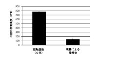
- FIG. 8 is a diagram showing a state in which contact by spraying is performed in Example 3.
- FIG. 9 is a graph showing the carbon dioxide concentration in the container after contact in Example 3.
- FIG. 10 is a diagram showing contact means in the third embodiment.
- FIG. 11 is a graph showing the carbon dioxide concentration in the container after contact in Example 3.
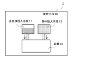
- FIG. 12 is a schematic view showing an example of the contact means.
- FIG. 13 is a diagram showing an example of a container.
- the method for fixing carbon dioxide of the present invention includes, for example, a contact step in which a mixed solution containing sodium hydroxide and calcium chloride is brought into contact with a gas containing carbon dioxide.
- the concentration of the sodium hydroxide in the mixed solution is less than 0.2 N.
- the concentration of the sodium hydroxide in the mixed solution is 0.05 N or more.
- the concentration of calcium chloride in the mixed solution is 0.05 mol / L or more.
- the gas is bubbling into the mixture to bring the mixture into contact with the gas.
- the mixed solution is brought into contact with the gas in a state where the mixed solution is shaken.
- the mixed solution is brought into contact with the gas in a state of being atomized.
- the contact step includes a first contact step and a second contact step.
- a mixture containing sodium hydroxide and a gas containing carbon dioxide are brought into contact with each other.
- calcium chloride is added to the mixed solution, and the mixed solution is brought into contact with a gas containing carbon dioxide.
- the device for producing immobilized carbon dioxide of the present invention includes, for example, a contacting means for bringing a mixture containing sodium hydroxide and calcium chloride into contact with a gas containing carbon dioxide.
- the device for producing immobilized carbon dioxide of the present invention is, for example, a means by which the contact means brings the gas into contact with the mixture by bubbling the gas into the mixture.
- the device for producing immobilized carbon dioxide of the present invention is, for example, a means for bringing the mixed solution into contact with the gas in a state where the contacting means generates a flow in the mixed solution.
- the device for producing immobilized carbon dioxide of the present invention is, for example, a means for bringing the mixed solution into contact with the gas while the contacting means is shaking the mixed solution.
- the device for producing immobilized carbon dioxide of the present invention includes, for example, a container for the contact means to make contact between the mixture and a gas containing carbon dioxide.
- the container includes a plurality of secondary containers.
- the mixed solution and the gas can be brought into contact with each other.
- the container has a polygonal cross section at the bottom surface.
- the container has a non-regular polygonal cross section at the bottom surface.
- the container includes a network structure.
- the mixed liquid flows through the network structure, so that the mixed liquid can come into contact with the gas.
- the device for producing immobilized carbon dioxide of the present invention is, for example, a means by which the contact means brings the mixed solution into contact with the gas in a state where the mixed solution is atomized.
- the method for fixing carbon dioxide of the present invention is a mixture containing sodium hydroxide (NaOH) and further containing at least one of a chloride of a Group 2 element (alkaline earth metal) and a chloride of a divalent metal element. It includes a contacting step of bringing the liquid into contact with a gas containing carbon dioxide (CO 2).
- CO 2 gas containing carbon dioxide
- the Group 2 element is not particularly limited, and examples thereof include beryllium, magnesium, calcium, strontium, barium, and radium, and examples thereof include calcium, magnesium, strontium, and barium.
- Examples of the chloride of the Group 2 element include calcium chloride, magnesium chloride, strontium chloride, and barium chloride.
- the divalent metal element is not particularly limited, and examples thereof include zinc.
- Examples of the chloride of the divalent metal element include zinc chloride.
- the mixed solution contains calcium chloride as the chloride of the group 2 element (alkaline earth metal)
- the present invention is not limited to this.
- the method for fixing carbon dioxide of the present invention is a contact step in which a mixed solution containing sodium hydroxide (NaOH) and calcium chloride (CaCl 2 ) is brought into contact with a gas containing carbon dioxide (CO 2). including.
- a mixed solution containing sodium hydroxide (NaOH) and calcium chloride (CaCl 2 ) is brought into contact with a gas containing carbon dioxide (CO 2).
- CO 2 carbon dioxide
- other configurations and conditions are not particularly limited.
- fixation of carbon dioxide means reducing the concentration of carbon dioxide in the gas by, for example, removing carbon dioxide from a gas containing carbon dioxide.
- the gas containing carbon dioxide is not particularly limited, and examples thereof include combustion exhaust gas, indoor air, and air.
- the concentration of carbon dioxide in the gas containing carbon dioxide is not particularly limited, and is, for example, 0 to 100%. As will be described later, according to the present invention, even low-concentration carbon dioxide can be fixed. Further, since a white precipitate is formed in the mixed solution by bubbling 100% carbon dioxide, the present invention can obtain an effect even in fixing carbon dioxide at a high concentration.
- the temperature of the gas containing carbon dioxide is not particularly limited, and may be, for example, a low temperature of 0 ° C. or lower, a general temperature of atmospheric temperature or room temperature, a temperature of less than 100 ° C., and a high temperature of 120 to 200 ° C.
- the temperature of the gas is preferably low from the viewpoint of preventing evaporation of water.
- the present invention can be applied, for example, even if the gas containing carbon dioxide has a high heat.
- the gas containing carbon dioxide may contain, for example, a substance other than carbon dioxide.
- Substances other than the carbon dioxide is not particularly limited, for example, SOx, NOx, O 2, dust, and the like.
- the mixed solution is basically alkaline, it is considered that a neutralization reaction occurs between the mixed solution and the acidic substance or the like.
- the present invention is not limited to this.
- the mixed solution contains sodium hydroxide and calcium chloride as described above.
- the method for producing the mixed solution is not particularly limited, and examples thereof include low-concentration mixing.
- the low concentration is, for example, less than 5N as the concentration of sodium hydroxide before mixing. According to the low concentration mixing, for example, the formation of a calcium hydroxide precipitate can be prevented.
- the method for preparing the mixed solution can be prepared by, for example, putting a 0.1 N sodium hydroxide solution and a 0.1 mol / L calcium chloride solution in a container and then mixing them. it can.
- the concentration of the sodium hydroxide is not particularly limited, and is, for example, 0.01 N or more and 0.05 N or more, and 0.2 N or less, less than 0.2 N, and 0.1 N or less.
- the unit "N" of the concentration indicates a normality, and in the case of sodium hydroxide, 0.01N is 0.01 mol / L.
- concentration of the sodium hydroxide is 0.01 N or more and 0.05 N or more, for example, more carbon dioxide can be fixed.
- the concentration of the sodium hydroxide is less than 0.2 N and 0.1 N or less, for example, more carbon dioxide can be fixed.
- the method for fixing carbon dioxide of the present invention calcium chloride and the high-concentration sodium hydroxide are contained even when the mixed solution contains a high concentration of sodium hydroxide. It means that it is possible to reduce the concentration of sodium hydroxide in the mixed solution by causing the precipitation of calcium hydroxide by the reaction. Therefore, according to the method for fixing carbon dioxide of the present invention, for example, even when a high concentration of sodium hydroxide is generated due to high heat, the concentration can be lowered and the generation of harmful gas can be suppressed. it can.
- the concentration of calcium chloride is not particularly limited, and is, for example, 0.005 mol / L or more and 0.05 mol / L or more, and 0.5 mol / L or less, less than 0.5 mol / L, and 0.1 mol / L. It is L or less.
- concentration of calcium chloride is within the above range, for example, more carbon dioxide can be fixed.
- the temperature of the mixed solution is not particularly limited, and is, for example, 30 to 100 ° C. According to the present invention, as described above, even when a high concentration of sodium hydroxide is generated due to high heat, for example, the concentration can be reduced. Therefore, the present invention can be applied, for example, even when the mixed solution has a high heat.
- the pH of the mixture is not particularly limited, and for example, the pH of the mixture containing 0.05 N sodium hydroxide and 0.05 mol / L calcium chloride is about 12.
- the method of bringing the mixed solution into contact with the gas containing carbon dioxide is not particularly limited, and for example, by bubbling the gas into the mixed solution, the mixed solution and the gas can be brought into contact with each other.
- the mixed solution and the gas are brought into contact with each other, and the mixed solution is atomized. Examples thereof include contact with a gas.
- the mixed solution and the gas may be brought into contact with each other in a state where the gas is recirculated.
- the bubbling conditions are not particularly limited, and for example, 3 mL in a 10 mL test tube.
- 0.1 N sodium hydroxide solution and 3 mL of the calcium chloride solution of 0.1 mol / L were added and mixed, and carbon dioxide (manufactured by Koike Kogyo Co., Ltd.) was used in the mixed solution for 10 seconds (about 20 cm).
- carbon dioxide manufactured by Koike Kogyo Co., Ltd.
- the bubbling can, for example, eject carbon dioxide from the tip of a Pasteur pipette.
- the bubbling time can be appropriately set, for example, as long as the formed precipitate does not disappear by a further reaction.
- the contacting conditions are not particularly limited, and for example, a PET having a volume of 2 L and having a general shape is not particularly limited.
- a PET having a volume of 2 L and having a general shape is not particularly limited.
- 10 mL of the mixed solution can be put into the PET bottle, and the PET bottle can be allowed to stand upright with the bottom surface facing down.
- the contact time can be, for example, 15 minutes, 30 minutes, and 60 minutes after the contact, and overnight contact.
- contacting the mixed solution with the gas while generating a flow in the mixed solution means, for example, that the mixed solution and the gas are brought into contact with each other while the mixed solution is shaken.
- the mixed solution may be brought into contact with the gas, or the mixed solution may be brought into contact with the gas by flowing the mixed solution in the container.
- the shaking conditions are not particularly limited, and for example, 10 mL of the mixed solution is added.
- An octagonal plastic bottle (commercially available) can be shaken using a shaker (BR-21UM, manufactured by TAITEK) at 120 rpm.
- the shaking conditions are as follows: For example, a container having a volume of 2 L containing 50 mL of the mixed solution is vigorously shaken by an adult male hand 1 to 4 times with one shaking for 30 seconds. be able to. The shaking 1 to 4 times can be performed, for example, immediately after the contact, 30 seconds, 2 minutes, 5 minutes, and 4 hours, respectively.
- the contacting conditions are not particularly limited, and for example, a container having a volume of 2 L containing the gas.
- a sprayer commercially available.
- the contacting means for bringing the mixture containing sodium hydroxide and calcium chloride into contact with the gas containing carbon dioxide is not particularly limited, and the description of the device for producing immobilized carbon dioxide, which will be described later. Can be used.
- the contact step includes, for example, a first contact step and a second contact step, and the first contact step involves contacting a mixed solution containing sodium hydroxide with a gas containing carbon dioxide, and the first contact step.
- the first contact step involves contacting a mixed solution containing sodium hydroxide with a gas containing carbon dioxide, and the first contact step.
- calcium chloride may be added to the mixed solution, and the mixed solution may be brought into contact with a gas containing carbon dioxide.
- a mixture containing sodium hydroxide and a gas containing carbon dioxide are brought into contact with each other.
- sodium hydrogen carbonate (NaHCO 3 ) and sodium carbonate (Na 2 CO 3 ) are produced by the reaction of sodium hydroxide and carbon dioxide, and the first carbon dioxide can be fixed. ..
- calcium chloride is not added in the first contact step. Therefore, in the first contact step, for example, even when a high concentration of sodium hydroxide is used, calcium hydroxide is not generated by the reaction with calcium chloride. Further, according to the first contact step, for example, the concentration of sodium hydroxide can be set to 0.1 N or less. Therefore, in the subsequent second contact step, it is possible to prevent calcium hydroxide from being generated by the reaction of calcium chloride with high-concentration sodium hydroxide, and it is possible to fix more carbon dioxide.
- the second contact step calcium chloride is added to the mixed solution, and the mixed solution is brought into contact with a gas containing carbon dioxide.
- a gas containing carbon dioxide By reacting sodium hydroxide and calcium chloride with carbon dioxide by the second contact step, calcium carbonate can be generated and carbon dioxide can be fixed.
- the above-mentioned description of the contact step can be incorporated.
- the method for producing immobilized carbon dioxide of the present invention includes an immobilization step of immobilizing carbon dioxide, and the immobilization step is carried out by the method of immobilizing carbon dioxide of the present invention.
- the method for producing immobilized carbon dioxide of the present invention is characterized by including the immobilization step, and other steps and conditions are not particularly limited.
- the method for fixing carbon dioxide of the present invention is as described above.
- the conditions of the immobilization step are not particularly limited, and are, for example, the same as those described in the method for immobilizing carbon dioxide of the present invention.
- the device for producing immobilized carbon dioxide of the present invention includes a contacting means for bringing a mixture containing sodium hydroxide and calcium chloride into contact with a gas containing carbon dioxide.
- the mixed solution and the gas containing carbon dioxide are, for example, the same as those described in the method for fixing carbon dioxide of the present invention.
- the contacting means is not particularly limited as long as the mixture containing sodium hydroxide and calcium chloride can be brought into contact with the gas containing carbon dioxide.
- FIG. 12 shows a schematic view showing an example of the contact means.
- the immobilized carbon dioxide production apparatus 1 includes the contact means 10, and the contact means 10 includes, for example, a mixed liquid charging means 11 for charging the mixed liquid and a gas containing the carbon dioxide.
- a gas charging means 12 for charging the mixture and a container 13 for contacting the mixed solution with a gas containing carbon dioxide.
- Examples of the contact means 10 include means for bringing the mixed solution into contact with the gas by bubbling the gas into the mixed solution.
- the bubbling is, for example, as described above.
- Examples of the contact means 10 include means for bringing the mixed solution into contact with the gas in a state where the mixed solution is allowed to stand or a flow is generated in the mixed solution.
- the mixed liquid and the gas are brought into contact with each other while the mixed liquid is generated to flow means, for example, that the mixed liquid and the gas are brought into contact with each other in a state where the mixed liquid is shaken as described above.
- the mixed solution may be brought into contact with the gas, or the mixed solution may be brought into contact with the gas by flowing the mixed solution in the container. When the mixed solution is flowed, the mixed solution may be flowed in one direction or recirculated.
- Examples of the contact means 10 include means for the contact means to bring the mixed solution into contact with the gas in a state where the mixed solution is atomized.
- Examples of the contact means 10 include means for bringing the mixed solution into contact with the gas in a state where the contact means has recirculated the gas.
- the contact means 10 may be, for example, a closed system or an open system in which the gas or the like can move to the outside world.
- the mixed liquid charging means 11 is not particularly limited as long as the mixed liquid can be charged, and examples thereof include a sprayer and the like.
- the gas charging means 12 is not particularly limited as long as the gas containing carbon dioxide can be charged, and examples thereof include a Pasteur pipette and the like.
- the container 13 is not particularly limited as long as the mixed solution can be brought into contact with a gas containing carbon dioxide.
- the size of the container 13 can be appropriately set according to, for example, the amount of the gas containing carbon dioxide.
- Examples of the material of the container 13 include plastic, glass, and ceramics.
- the shape of the container 13 can be appropriately set according to the mode of contact between the mixed solution and the gas containing carbon dioxide, for example. Specifically, for example, as described above, when the mixed solution is brought into contact with the gas in a state where the mixed solution is shaken, the shape of the container 13 is such that the cross section of the bottom surface is polygonal. Is preferable.
- the polygonal shape is, for example, a non-regular polygonal shape.
- the polygonal shape is, for example, an octagonal shape.
- Specific examples of the shape of the container 13 include the shape of a polygonal pillar and the shape of an octagonal pillar as shown in FIG.
- the cross section of the bottom surface of the container 13 has a polygonal shape, more carbon dioxide can be fixed as described later. It is considered that this is because, for example, in the shaking, the surface area of the mixture is increased so that the gas containing more carbon dioxide can be contacted.
- the present invention is not limited to this.
- a plurality of containers 13 are used. May include a secondary container of. Then, for example, the mixed solution may be brought into contact with the gas by sequentially flowing through the plurality of secondary containers.
- the secondary container can have, for example, a basin-like structure having a shallow water depth, as shown in FIG. 13 (A).
- the plurality of secondary containers may have, for example, a structure in which they are stacked at intervals in the vertical direction. Thereby, for example, the mixed solution can be sequentially flowed from the upper secondary container to the lower secondary container.
- the container 13 is, for example, a network structure. May include. Then, for example, the mixed liquid may be able to come into contact with the gas by flowing through the network structure.
- the mesh-like structure include a mesh-like structure and a branched structure such as a cedar leaf-like structure as shown in FIG. 13 (B). The size, fineness, etc. of the network structure can be appropriately set.
- the network structure can be formed, for example, as an aggregate of a plurality of plate-like, granular or rod-like structures.
- the material for forming the network structure is not particularly limited, and examples thereof include plastic.
- Example 1 In the container, contacting by bubbling sodium hydroxide (NaOH), and a mixture containing calcium chloride (CaCl 2), and a gas containing carbon dioxide (CO 2), and the gas in the liquid mixture By doing so, it was confirmed that carbon dioxide could be fixed.
- NaOH sodium hydroxide
- CaCl 2 calcium chloride
- CO 2 carbon dioxide
- a 1N sodium hydroxide solution (manufactured by Wako Pure Chemical Industries, Ltd.) was diluted with distilled water so as to be 0.01, 0.02, 0.1, 0.2, and 0.4N, respectively, to prepare a sodium hydroxide solution having each concentration. .. Further, a 1 mol / L calcium chloride solution (manufactured by Wako Pure Chemical Industries, Ltd.) was diluted with distilled water so as to be 0.01, 0.02, 0.1, 0.2, and 1 (undiluted) mol / L, respectively. A concentrated calcium chloride solution was prepared.
- FIG. 1 is a photograph of a mixture containing 0.05 N sodium hydroxide and 0.05 mol / L calcium chloride before and after contact with carbon dioxide, and the left side in the figure is before the contact. The right side shows the state of the test tube after the contact.
- contact with carbon dioxide produced a white precipitate of calcium carbonate (CaCO 3) in the mixed solution.
- CaCO 3 calcium carbonate
- FIG. 2 is a graph showing the weight of the precipitate formed in the mixed solution due to the contact with the carbon dioxide.
- the vertical axis represents the weight (g) of the precipitate per test tube
- the horizontal axis represents the sodium hydroxide concentration (N) in the mixture.
- the value of the weight of the precipitate was taken as the average value of the measured values of a total of 5 samples for each sample of the mixed solution.
- the concentration was 0.05 N
- the concentration was greatly increased
- the concentration was 0.1 N the amount of the precipitate was the maximum.
- the concentration was 0.2 N
- the amount of the precipitate decreased as compared with the value at 0.1 N. It was confirmed that more carbon dioxide could be fixed at the concentrations of 0.05 to 0.2 N and 0.05 to 0.1 N.
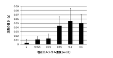
- FIG. 3 is a graph showing the weight of the precipitate formed in the mixed solution due to the contact with the carbon dioxide.
- the vertical axis represents the weight (g) of the precipitate per test tube, and the horizontal axis represents the calcium chloride concentration (mol / L) in the mixed solution.
- the value of the weight of the precipitate was taken as the average value of the measured values of a total of 5 samples for each sample of the mixed solution.
- the precipitate was formed.
- carbon dioxide is produced by bringing a mixed solution containing sodium hydroxide and calcium chloride and a gas containing carbon dioxide into contact with each other in the container by bubbling the gas into the mixed solution. It was confirmed that it could be fixed.
- Example 2 Confirmed that carbon dioxide can be fixed by contacting a mixture containing sodium hydroxide and calcium chloride with a gas containing carbon dioxide in a container in a state where the mixture is allowed to stand or shaken. did.
- FIG. 4 is a graph showing the carbon dioxide concentration in the PET bottle after the contact.
- the vertical axis represents the carbon dioxide concentration (PPM)
- the horizontal axis represents the elapsed time (minutes) after the contact.
- the value of the carbon dioxide concentration was the average value of the measured values of a total of 4 samples for 0 minutes (immediately after the contact), 15 minutes, 30 minutes, and 60 minutes after the contact. After the overnight contact, the measured values of a total of 6 samples were 0 PPM.
- the contact reduced the carbon dioxide concentration in the PET bottle according to the elapsed time after the contact. Further, since the value of the carbon dioxide concentration became 0 PPM after the contact in the overnight, it was found that even a low concentration of carbon dioxide can be fixed according to the present invention.
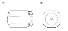
- FIG. 5A is a side view of the octagonal pillar plastic bottle
- FIG. 5B is a view of the octagonal pillar plastic bottle seen from the bottom surface.
- the shaker was shaken using a shaker (BR-21UM, manufactured by TAITEK) under the condition of 120 rpm.
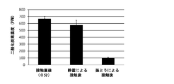
- FIG. 6 is a graph showing the carbon dioxide concentration in the octagonal pillar plastic bottle after the contact.
- the vertical axis shows the carbon dioxide concentration (PPM)
- the horizontal axis shows from the left immediately after the contact (0 minutes), after the contact by the stationary state, and after the contact by the shaking.
- the carbon dioxide concentration value was taken as the average value of the measured values of a total of 4 samples.
- the contact by the shaking reduced the carbon dioxide concentration in the octagonal pillar plastic bottle as compared with immediately after the contact.
- the contact by the shaking greatly reduces the carbon dioxide concentration in the octagonal pillar plastic bottle to about 1/6 as compared with immediately after the contact, and can fix more carbon dioxide. It was.
- the contact by shaking reduced the carbon dioxide concentration more significantly than the case where the contact by standing was performed. It is considered that the reason for this is that the surface area of the mixture has increased due to the shaking, and it has become possible to come into contact with a gas containing more carbon dioxide. Further, it is considered that the surface area of the mixed liquid is further increased because the bottom of the octagonal pillar plastic bottle is flatter and shorter than that of the PET bottle having a general shape.
- the contact was performed by changing the shaking conditions.
- a PET bottle having a volume of 2 L and having the general shape was used. Twelve hours before the contact, the lid of the PET bottle was opened, the tip of the Pasteur pipette was inserted into the mouth of the PET bottle, and carbon dioxide was injected from the tip. Then, after putting 50 mL of the mixed solution into the PET bottle, the mixture was shaken violently by an adult man 1 to 6 times with one shaking for 30 seconds. The first contact by the shaking is performed immediately after the contact, and the second to sixth contact by the shaking is performed 2 minutes, 5 minutes, and 15 minutes, respectively, immediately after the contact. It was performed after the lapse, 30 minutes, and 60 minutes. Then, after the 1 to 6 times of the contact, the carbon dioxide concentration was measured using a carbon dioxide detector (XP-3140, manufactured by COSMO), respectively.
- XP-3140 carbon dioxide detector
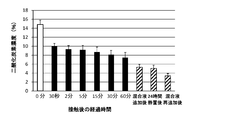
- FIG. 7 is a graph showing the carbon dioxide concentration in the PET bottle after the contact.
- the vertical axis indicates the carbon dioxide concentration (%)
- the horizontal axis indicates the carbon dioxide concentration (%) from the left, immediately after the contact (0 minutes), after the first contact by the shaking (30 seconds), and the second contact.
- the following shows after the sixth shaking (60 minutes), after adding the mixed solution, allowing to stand for 24 hours, and after re-adding the mixed solution.
- the carbon dioxide concentration value was taken as the average value of the measured values of a total of 5 samples. As shown in FIG.
- carbon dioxide is produced by bringing the mixture containing sodium hydroxide and calcium chloride into contact with the gas containing carbon dioxide in the container in a state where the mixture is allowed to stand or shaken. It was confirmed that it can be fixed.
- Example 3 It was confirmed that carbon dioxide can be fixed by contacting a mixture containing sodium hydroxide and calcium chloride and a gas containing carbon dioxide in a container in a atomized state.
- a mixed solution containing the sodium hydroxide and the calcium chloride was prepared in the same manner as in Example 2.
- a PET bottle having a general shape having a volume of 2 L the inside of the PET bottle was equilibrated with the atmosphere in the same manner as in Example 2.
- about 4 mL of the mixed solution was sprayed onto the PET bottle 10 times at 5-second intervals using a sprayer (commercially available) to bring the mixed solution into contact with carbon dioxide.
- a sprayer commercially available
- FIG. 9 is a graph showing the carbon dioxide concentration in the PET bottle after the contact.
- the vertical axis shows the carbon dioxide concentration (PPM), and the horizontal axis shows from the left immediately after the contact (0 minutes) and after the contact by the spray.
- the carbon dioxide concentration value was taken as the average value of the measured values of a total of 4 samples.
- the contact by the spray greatly reduced the carbon dioxide concentration in the PET bottle to about 1/6 as compared with immediately after the contact.
- the carbon dioxide concentration was greatly reduced in a short time by the contact by the spray. It is considered that the reason for this is that by contacting the mixed solution in a mist state, the surface area of the mixed solution is greatly increased, and it becomes possible to contact the gas containing more carbon dioxide.
- the contact means for making the contact was produced as follows. As shown in FIG. 10, two boxes (commercially available) which are milk cartons are connected in an L shape, and holes are made in two places on the side surface of the box at the bottom by partially cutting the holes. An air injection part and a carbon dioxide injection part were provided by inserting a silicon tube from the inside. Further, a hole was similarly formed in the upper surface of the box at the bottom so that the mixed solution could be sprayed into the inside of the box from the sprayer. The joints of the upper and lower boxes, respectively, were opened with large cuts to allow carbon dioxide to rise from the lower box to the upper box. A gauze layer was provided on the connecting portion with a quadruple gauze (commercially available). The upper surface of the upper box was opened. Further, a hole was similarly formed on the side surface of the upper box, and a nozzle of a carbon dioxide concentration detector (XP-3140, manufactured by COSMO) was installed.
- XP-3140 nozzle of a carbon dioxide concentration detector
- the flow rate of air from the air injection section is about 100 cm 3 / sec, and the flow rate of carbon dioxide from the carbon dioxide injection section is 10 cm 3 / sec, and injection is performed until the measured value of carbon dioxide concentration becomes constant. went. Then, the mixed solution was sprayed from the sprayer 10 times in a row. The spray amount of the mixed solution was about 4 mL in total after 10 times. Approximately 20 seconds after the spraying, the measured value of carbon dioxide concentration became the lowest value.
- FIG. 11 is a graph showing the carbon dioxide concentration in the box when the measured value of carbon dioxide reaches the minimum value about 20 seconds after the contact.
- the vertical axis shows the carbon dioxide concentration (%), and the horizontal axis shows from the left, before the contact and after the contact by the spray.
- the carbon dioxide concentration value was taken as the average value of the measured values of a total of 10 samples.
- the contact by the spray reduced the carbon dioxide concentration in the box as compared with immediately after the contact.
- carbon dioxide can be fixed by bringing the mixture containing sodium hydroxide and calcium chloride into contact with the gas containing carbon dioxide in the state of atomizing the mixture in the container. Was confirmed.
- the present invention it is possible to provide a new method for fixing carbon dioxide. Therefore, it can be said that the present invention is extremely useful in the treatment of combustion exhaust gas containing carbon dioxide.
Landscapes
- Chemical & Material Sciences (AREA)
- Engineering & Computer Science (AREA)
- Environmental & Geological Engineering (AREA)
- Organic Chemistry (AREA)
- Chemical Kinetics & Catalysis (AREA)
- Analytical Chemistry (AREA)
- General Chemical & Material Sciences (AREA)
- Oil, Petroleum & Natural Gas (AREA)
- Biomedical Technology (AREA)
- Health & Medical Sciences (AREA)
- Inorganic Chemistry (AREA)
- Life Sciences & Earth Sciences (AREA)
- Geology (AREA)
- Carbon And Carbon Compounds (AREA)
- Treating Waste Gases (AREA)
- Gas Separation By Absorption (AREA)
Abstract
新たな、二酸化炭素の固定方法を提供する。 本発明の二酸化炭素の固定方法は、水酸化ナトリウムを含み、さらに、第2族元素の塩化物、および2価の金属元素の塩化物の少なくとも一方を含む混合液と、二酸化炭素を含む気体とを接触させる接触工程を含む。
Description
本発明は、二酸化炭素の固定方法、固定化二酸化炭素の製造方法、および固定化二酸化炭素の製造装置に関する。
二酸化炭素の固定方法として、例えば、特許文献1には、水酸化ナトリウム水溶液に二酸化炭素を含む燃焼排ガスを反応させることにより、炭酸ナトリウムを生成させる方法が記載されている。しかし、新たな、二酸化炭素の固定方法が求められている。
そこで、本発明は、新たな、二酸化炭素の固定方法、固定化二酸化炭素の製造方法、および固定化二酸化炭素の製造装置の提供を目的とする。
前記目的を達成するために、本発明の二酸化炭素の固定方法は、水酸化ナトリウムを含み、さらに、第2族元素の塩化物、および2価の金属元素の塩化物の少なくとも一方を含む混合液と、二酸化炭素を含む気体とを接触させる接触工程を含む。
本発明の固定化二酸化炭素の製造方法は、二酸化炭素を固定化する固定化工程を含み、
前記固定化工程が、本発明の二酸化炭素の固定方法により実施される。
前記固定化工程が、本発明の二酸化炭素の固定方法により実施される。
本発明の固定化二酸化炭素の製造装置は、水酸化ナトリウムを含み、さらに、第2族元素の塩化物、および2価の金属元素の塩化物の少なくとも一方を含む混合液と、二酸化炭素を含む気体とを接触させるための接触手段を含む。
本発明によれば、新たな、二酸化炭素の固定方法を提供することができる。
本発明の二酸化炭素の固定方法は、例えば、水酸化ナトリウム、および塩化カルシウムを含む混合液と、二酸化炭素を含む気体とを接触させる接触工程を含む。
本発明の二酸化炭素の固定方法は、例えば、前記混合液における前記水酸化ナトリウムの濃度が、0.2N未満である。
本発明の二酸化炭素の固定方法は、例えば、前記混合液における前記水酸化ナトリウムの濃度が、0.05N以上である。
本発明の二酸化炭素の固定方法は、例えば、前記混合液における前記塩化カルシウムの濃度が、0.05mol/L以上である。
本発明の二酸化炭素の固定方法は、例えば、前記接触工程において、前記気体を前記混合液中にバブリングすることにより、前記混合液と前記気体とを接触させる。
本発明の二酸化炭素の固定方法は、例えば、前記接触工程において、前記混合液を振とうさせた状態で、前記混合液と前記気体とを接触させる。
本発明の二酸化炭素の固定方法は、例えば、前記接触工程において、前記混合液を霧状にした状態で、前記混合液と前記気体とを接触させる。
本発明の二酸化炭素の固定方法は、例えば、前記接触工程が、第1の接触工程および第2の接触工程を含み、
前記第1の接触工程は、水酸化ナトリウムを含む混合液と、二酸化炭素を含む気体とを接触させ、
前記第2の接触工程は、前記混合液に、塩化カルシウムを添加し、さらに、前記混合液と、二酸化炭素を含む気体とを接触させる。
前記第1の接触工程は、水酸化ナトリウムを含む混合液と、二酸化炭素を含む気体とを接触させ、
前記第2の接触工程は、前記混合液に、塩化カルシウムを添加し、さらに、前記混合液と、二酸化炭素を含む気体とを接触させる。
本発明の固定化二酸化炭素の製造装置は、例えば、水酸化ナトリウム、および塩化カルシウムを含む混合液と、二酸化炭素を含む気体とを接触させるための接触手段を含む。
本発明の固定化二酸化炭素の製造装置は、例えば、前記接触手段が、前記気体を前記混合液中にバブリングすることにより、前記混合液と前記気体とを接触させる手段である。
本発明の固定化二酸化炭素の製造装置は、例えば、前記接触手段が、前記混合液に流れを発生させた状態で、前記混合液と前記気体とを接触させる手段である。
本発明の固定化二酸化炭素の製造装置は、例えば、前記接触手段が、前記混合液を振とうさせた状態で、前記混合液と前記気体とを接触させる手段である。
本発明の固定化二酸化炭素の製造装置は、例えば、前記接触手段が、前記混合液と二酸化炭素を含む気体との接触を行うための容器を含む。
本発明の固定化二酸化炭素の製造装置は、例えば、前記容器は、複数の二次容器を含み、
前記混合液が、前記複数の二次容器内を、順次、流れることで、前記混合液と前記気体との接触が可能である。
前記混合液が、前記複数の二次容器内を、順次、流れることで、前記混合液と前記気体との接触が可能である。
本発明の固定化二酸化炭素の製造装置は、例えば、前記容器は、底面の断面が、多角形状である。
本発明の固定化二酸化炭素の製造装置は、例えば、前記容器は、底面の断面が、非正多角形状である。
本発明の固定化二酸化炭素の製造装置は、例えば、前記容器は、網目状構造体を含み、
前記混合液が、前記網目状構造体を、流れることで、前記混合液と前記気体との接触が可能である。
前記混合液が、前記網目状構造体を、流れることで、前記混合液と前記気体との接触が可能である。
本発明の固定化二酸化炭素の製造装置は、例えば、前記接触手段が、前記混合液を霧状にした状態で、前記混合液と前記気体とを接触させる手段である。
本明細書で使用する用語は、特に言及しない限り、当該技術分野で通常用いられる意味で用いることができる。
以下に、本発明の実施形態について、図面を参照して説明する。
(二酸化炭素の固定方法)
本発明の二酸化炭素の固定方法は、水酸化ナトリウム(NaOH)を含み、さらに、第2族元素(アルカリ土類金属)の塩化物、および2価の金属元素の塩化物の少なくとも一方を含む混合液と、二酸化炭素(CO2)を含む気体とを接触させる接触工程を含む。本発明の二酸化炭素の固定方法において、その他の構成及び条件は、特に制限されない。
本発明の二酸化炭素の固定方法は、水酸化ナトリウム(NaOH)を含み、さらに、第2族元素(アルカリ土類金属)の塩化物、および2価の金属元素の塩化物の少なくとも一方を含む混合液と、二酸化炭素(CO2)を含む気体とを接触させる接触工程を含む。本発明の二酸化炭素の固定方法において、その他の構成及び条件は、特に制限されない。
前記第2族元素は、特に制限されず、例えば、ベリリウム、マグネシウム、カルシウム、ストロンチウム、バリウム、ラジウムがあげられ、中でも、例えば、カルシウム、マグネシウム、ストロンチウム、バリウムがあげられる。前記第2族元素の塩化物は、例えば、塩化カルシウム、塩化マグネシウム、塩化ストロンチウム、塩化バリウムがあげられる。
前記2価の金属元素は、特に制限されず、例えば、亜鉛があげられる。前記2価の金属元素の塩化物は、例えば、塩化亜鉛があげられる。
以下の説明において、前記混合液が、前記第2族元素(アルカリ土類金属)の塩化物として、塩化カルシウムを含む場合を例にあげて、説明を行う。ただし、本発明は、これには制限されない。
本発明の二酸化炭素の固定方法は、前述のように、水酸化ナトリウム(NaOH)、および塩化カルシウム(CaCl2)を含む混合液と、二酸化炭素(CO2)を含む気体とを接触させる接触工程を含む。本発明の二酸化炭素の固定方法において、その他の構成及び条件は、特に制限されない。
本発明の二酸化炭素の固定方法によれば、前記接触工程を含むことにより、水酸化ナトリウムおよび塩化カルシウムと、二酸化炭素とを反応させ、炭酸カルシウム(CaCO3)を生じさせることで、二酸化炭素を固定することができる。
本発明において、「二酸化炭素の固定(固定化ともいう。)」は、例えば、二酸化炭素を含む気体から、二酸化炭素を除去することにより、前記気体中の二酸化炭素濃度を低減させることをいう。
前記二酸化炭素を含む気体は、特に制限されず、例えば、燃焼排ガス、室内空気、および大気等があげられる。
前記二酸化炭素を含む気体における二酸化炭素の濃度は、特に制限されず、例えば、0~100%である。なお、後述するように、本発明によれば、低濃度の二酸化炭素であっても、固定することができる。また、100%の二酸化炭素のバブリングにより、前記混合液において、白色沈殿が形成されることから、本発明は、高濃度の二酸化炭素固定においても、効果を得ることができる。
前記二酸化炭素を含む気体の温度は、特に制限されず、例えば、0℃以下の低温、大気中の気温や室温の一般的な温度、100℃未満、および120~200℃の高温でもよい。なお、前記気体の温度は、水の蒸発を防ぐ観点から、低温であることが好ましい。ただし、本発明によれば、後述するように、例えば、高熱による、高濃度の水酸化ナトリウムが発生した場合でも、その濃度を低下させることができる。このため、本発明は、例えば、前記二酸化炭素を含む気体が高熱であっても、適用することができる。
前記二酸化炭素を含む気体は、例えば、二酸化炭素以外の物質を含んでいてもよい。前記二酸化炭素以外の物質は、特に制限されず、例えば、SOx、NOx、O2、ダスト等があげられる。なお、本発明において、前記混合液は、例えば、基本的に、アルカリ性であることから、前記混合液と酸性の前記物質等とにおいて、中和反応が起こると考えられる。ただし、本発明はこれには制限されない。
前記混合液は、前述のように、水酸化ナトリウム、および塩化カルシウムを含む。前記混合液の作製方法は、特に制限されず、例えば、低濃度混合があげられる。前記低濃度は、例えば、前記混合前の水酸化ナトリウムの濃度として、5N未満があげられる。前記低濃度混合によれば、例えば、水酸化カルシウムの沈殿の形成を防ぐことができる。前記混合液の作製方法は、具体的には、例えば、0.1Nの水酸化ナトリウム溶液、および0.1mol/Lの塩化カルシウム溶液を、容器内にそれぞれ入れた後、混合することにより作製することができる。
前記混合液において、前記水酸化ナトリウムの濃度は、特に制限されず、例えば、0.01N以上、および0.05N以上、ならびに、0.2N以下、0.2N未満、および0.1N以下である。なお、前記濃度の単位「N」は、規定度を示し、水酸化ナトリウムの場合、0.01Nは、0.01mol/Lである。前記水酸化ナトリウムの濃度が、0.01N以上、および0.05N以上であることにより、例えば、より多くの二酸化炭素を固定できる。また、前記水酸化ナトリウムの濃度が、0.2N未満、および0.1N以下であることにより、例えば、より多くの二酸化炭素を固定できる。
なお、後述する実施例において示すように、前記水酸化ナトリウムの濃度が、0.2N以上では、前記接触において、塩化カルシウムと高濃度の水酸化ナトリウムとの反応により、水酸化カルシウム(Ca(OH)2)の沈殿が生じることで、前記接触による炭酸カルシウムの合成量が減少すると考えられる。
一方、このことは、言い換えると、本発明の二酸化炭素の固定方法によれば、前記混合液において、高濃度の水酸化ナトリウムが含まれる場合でも、塩化カルシウムと前記高濃度の水酸化ナトリウムとの反応により、水酸化カルシウムの沈殿が生じることで、前記混合液における水酸化ナトリウムの濃度を低下させることが可能であることを意味する。したがって、本発明の二酸化炭素の固定方法によれば、例えば、高熱による、高濃度の水酸化ナトリウムが発生した場合でも、その濃度を低下させることができ、有害な気体の発生を抑制することができる。
前記混合液において、前記塩化カルシウムの濃度は、特に制限されず、例えば、0.005mol/L以上、および0.05mol/L以上、ならびに、0.5mol/L以下、0.5mol/L未満、および0.1mol/L以下である。前記塩化カルシウムの濃度が、前記範囲内であることにより、例えば、より多くの二酸化炭素を固定できる。
前記混合液の温度は、特に制限されず、例えば、30~100℃である。なお、本発明によれば、前述のように、例えば、高熱による、高濃度の水酸化ナトリウムが発生した場合でも、その濃度を低下させることができる。このため、本発明は、例えば、前記混合液が高熱であっても、適用することができる。
前記混合液のpHは、特に制限されず、例えば、0.05Nの水酸化ナトリウムと0.05mol/Lの塩化カルシウムとを含む前記混合液のpHは、約12である。
前記接触工程において、前記混合液と、前記二酸化炭素を含む気体とを接触させる方法は、特に制限されず、例えば、前記気体を前記混合液中にバブリングすることにより、前記混合液と前記気体とを接触させる、前記混合液を静置または前記混合液に流れを発生させた状態で、前記混合液と前記気体とを接触させる、前記混合液を霧状にした状態で、前記混合液と前記気体とを接触させる等の方法があげられる。また、前記気体を環流させた状態で、前記混合液と前記気体とを接触させてもよい。
前記接触工程において、前記気体を前記混合液中にバブリングすることにより、前記混合液と前記気体とを接触させる場合、前記バブリングの条件は、特に制限されず、例えば、10mLの試験管に、3mLの0.1Nの水酸化ナトリウム溶液と、3mLの0.1mol/Lの前記塩化カルシウム溶液とを入れて混合し、前記混合液に、二酸化炭素(小池工業社製)を用いて、10秒間(約20cm3)、バブリングをすることができる。なお、前記バブリングは、例えば、パスツールピペットの先端から、二酸化炭素を噴出させることができる。前記バブリングを行う時間は、例えば、形成された沈殿が、さらなる反応により消失しない範囲で、適宜設定することができる。
前記接触工程において、前記混合液を静置させた状態で、前記混合液と前記気体とを接触させる場合、前記接触させる条件は、特に制限されず、例えば、容積2Lの一般的な形状のペットボトル(市販のもの)内を大気と平衡にした後、前記ペットボトルに、10mLの前記混合液を入れ、前記ペットボトルを、底面が下になるようにして立てて静置することができる。前記接触時間は、例えば、前記接触後、15分、30分、および60分、ならびにオーバーナイトでの接触とすることができる。
前記接触工程において、「前記混合液に流れを発生させた状態で、前記混合液と前記気体とを接触させる」とは、例えば、前記混合液を振とうさせた状態で、前記混合液と前記気体とを接触させてもよいし、容器内において、前記混合液を流すことにより、前記混合液と前記気体とを接触させてもよい。
前記接触工程において、前記混合液を振とうさせた状態で、前記混合液と前記気体とを接触させる場合、前記振とうの条件は、特に制限されず、例えば、10mLの前記混合液を入れた八角柱プラスチックボトル(市販のもの)を、シェイカー(BR-21UM、TAITEK製)を用いて、120rpmの条件で、振とうすることができる。また、前記振とうの条件は、例えば、50mLの前記混合液を入れた容積2Lの容器を、30秒間の振とうを1回として、1~4回、成人男性の手で、激しく振とうすることができる。前記1~4回の振とうは、例えば、それぞれ、前記接触直後、30秒後、2分後、5分後、4時間後に行うことができる。
前記接触工程において、前記混合液を霧状にした状態で、前記混合液と前記気体とを接触させる場合、前記接触させる条件は、特に制限されず、例えば、前記気体を入れた容積2Lの容器に、約4mLの前記混合液を、噴霧器(市販のもの)を用いて、5秒間隔で10回噴霧することができる。
前記接触工程において、水酸化ナトリウム、および塩化カルシウムを含む混合液と、二酸化炭素を含む気体とを接触させるための接触手段は、特に制限されず、後述する、固定化二酸化炭素の製造装置の記載を援用することができる。
前記接触工程は、例えば、第1の接触工程および第2の接触工程を含み、前記第1の接触工程は、水酸化ナトリウムを含む混合液と、二酸化炭素を含む気体とを接触させ、前記第2の接触工程は、前記混合液に、塩化カルシウムを添加し、さらに、前記混合液と、二酸化炭素を含む気体とを接触させてもよい。
前記第1の接触工程は、水酸化ナトリウムを含む混合液と、二酸化炭素を含む気体とを接触させる。前記第1の接触工程により、水酸化ナトリウムと二酸化炭素との反応により、炭酸水素ナトリウム(NaHCO3)や炭酸ナトリウム(Na2CO3)が生じ、第1の二酸化炭素の固定を行うことができる。
ここで、前記第1の接触工程において、塩化カルシウムは未添加である。このため、前記第1の接触工程において、例えば、高濃度の水酸化ナトリウムを用いた場合でも、塩化カルシウムとの反応により水酸化カルシウムが生じない。また、前記第1の接触工程によれば、例えば、水酸化ナトリウムの濃度を、0.1N以下にすることができる。このため、続く前記第2の接触工程において、塩化カルシウムと高濃度の水酸化ナトリウムとの反応により水酸化カルシウムが生じることを防ぐことができ、より多くの二酸化炭素を固定できる。
前記第2の接触工程は、前記混合液に、塩化カルシウムを添加し、さらに、前記混合液と、二酸化炭素を含む気体とを接触させる。前記第2の接触工程により、水酸化ナトリウムおよび塩化カルシウムと、二酸化炭素とを反応させることにより、炭酸カルシウムを生じさせ、二酸化炭素を固定することができる。
前記第1の接触工程および第2の接触工程は、例えば、前述の、前記接触工程についての説明を援用できる。
(固定化二酸化炭素の製造方法)
本発明の固定化二酸化炭素の製造方法は、前述のように、二酸化炭素を固定化する固定化工程を含み、前記固定化工程が、本発明の二酸化炭素の固定方法により実施される。本発明の固定化二酸化炭素の製造方法は、前記固定化工程を含むことが特徴であって、その他の工程および条件は、特に制限されない。本発明の二酸化炭素の固定方法は、前述の通りである。前記固定化工程の条件等は、特に制限されず、例えば、本発明の二酸化炭素の固定方法における記載と同様である。
本発明の固定化二酸化炭素の製造方法は、前述のように、二酸化炭素を固定化する固定化工程を含み、前記固定化工程が、本発明の二酸化炭素の固定方法により実施される。本発明の固定化二酸化炭素の製造方法は、前記固定化工程を含むことが特徴であって、その他の工程および条件は、特に制限されない。本発明の二酸化炭素の固定方法は、前述の通りである。前記固定化工程の条件等は、特に制限されず、例えば、本発明の二酸化炭素の固定方法における記載と同様である。
(固定化二酸化炭素の製造装置)
本発明の固定化二酸化炭素の製造装置は、前述のように、水酸化ナトリウム、および塩化カルシウムを含む混合液と、二酸化炭素を含む気体とを接触させるための接触手段を含む。前記混合液、および前記二酸化炭素を含む気体は、例えば、本発明の二酸化炭素の固定方法における記載と同様である。
本発明の固定化二酸化炭素の製造装置は、前述のように、水酸化ナトリウム、および塩化カルシウムを含む混合液と、二酸化炭素を含む気体とを接触させるための接触手段を含む。前記混合液、および前記二酸化炭素を含む気体は、例えば、本発明の二酸化炭素の固定方法における記載と同様である。
前記接触手段は、水酸化ナトリウム、および塩化カルシウムを含む混合液と、二酸化炭素を含む気体とを接触させることができればよく、特に制限されない。図12に、前記接触手段の一例を示す概略図を示す。図12に示すように、固定化二酸化炭素の製造装置1は、接触手段10を含み、接触手段10は、例えば、前記混合液を投入するための混合液投入手段11、前記二酸化炭素を含む気体を投入するための気体投入手段12、および前記混合液と二酸化炭素を含む気体との接触を行うための容器13を含む。
接触手段10は、例えば、前記気体を前記混合液中にバブリングすることにより、前記混合液と前記気体とを接触させる手段があげられる。前記バブリングは、例えば、前述の通りである。
接触手段10は、例えば、前記混合液を静置または前記混合液に流れを発生させた状態で、前記混合液と前記気体とを接触させる手段があげられる。「前記混合液に流れを発生させた状態で、前記混合液と前記気体とを接触させる」とは、例えば、前述のように、前記混合液を振とうさせた状態で、前記混合液と前記気体とを接触させてもよいし、容器内において、前記混合液を流すことにより、前記混合液と前記気体とを接触させてもよい。前記混合液を流す場合、前記混合液を一方向に流してもよいし、環流させてもよい。
接触手段10は、例えば、前記接触手段が、前記混合液を霧状にした状態で、前記混合液と前記気体とを接触させる手段があげられる。
接触手段10は、例えば、前記接触手段が、前記気体を環流させた状態で、前記混合液と前記気体とを接触させる手段があげられる。
接触手段10は、例えば、閉鎖系でもよいし、前記気体等が外界へ移動可能な、開放系でもよい。
混合液投入手段11は、前記混合液を投入することができればよく、特に制限されず、例えば、噴霧器等があげられる。気体投入手段12は、前記二酸化炭素を含む気体を投入することができればよく、特に制限されず、例えば、パスツールピペット等があげられる。
容器13は、前記混合液と二酸化炭素を含む気体との接触を行うことができればよく、特に制限されない。容器13の大きさは、例えば、前記二酸化炭素を含む気体の量に応じて、適宜設定することができる。容器13の素材は、例えば、プラスチック、ガラス、セラミックス等があげられる。
容器13の形状は、例えば、前記混合液と、前記二酸化炭素を含む気体との接触の態様に応じて、適宜設定することができる。具体的には、例えば、前述のように、前記混合液を振とうさせた状態で、前記混合液と前記気体とを接触させる場合、容器13の形状は、底面の断面が、多角形状であることが好ましい。前記多角形状は、例えば、非正多角形状である。前記多角形状は、例えば、八角形状である。容器13の形状は、具体的には、例えば、多角柱の形状、および、図5に示すような八角柱の形状があげられる。容器13の底面の断面が、多角形状であることにより、後述するように、より多くの二酸化炭素を固定できる。これは、例えば、前記振とうにおいて、前記混合液の表面積が増加し、より多くの前記二酸化炭素を含む気体と接触できるようになるためと考えられる。ただし、本発明は、これには制限されない。
また、例えば、前述のように、容器13内において、前記混合液を静置または前記混合液に流れを発生させた状態で、前記混合液と前記気体とを接触させる場合、容器13は、複数の二次容器を含んでもよい。そして、例えば、前記混合液が、前記複数の二次容器内を、順次、流れることで、前記混合液と前記気体との接触が可能であってもよい。前記二次容器は、例えば、図13(A)に示すように、水深の浅い、水盤状の構造とすることができる。前記複数の二次容器は、例えば、上下方向に間隔をあけて、それぞれを重ねた構造とすることができる。これにより、例えば、上側の前記二次容器から下側の前記二次容器に、前記混合液が、順次、流れることができる。
また、例えば、前述のように、前記混合液を静置または前記混合液に流れを発生させた状態で、前記混合液と前記気体とを接触させる場合、容器13は、例えば、網目状構造体を含んでもよい。そして、例えば、前記混合液が、前記網目状構造体を、流れることで、前記混合液と前記気体との接触が可能であってもよい。前記網目状構造体は、例えば、メシュ状構造、および、図13(B)に示すような、杉の葉状等の分岐構造等があげられる。前記網目状構造の大きさ、細かさ等は、適宜設定できる。前記網目状構造は、例えば、複数の、板状、粒状または棒状構造の集合体として形成することができる。前記網目状構造の形成材料は、特に制限されず、例えば、プラスチックがあげられる。
つぎに、本発明の実施例について説明する。ただし、本発明は、下記実施例により制限されない。市販の試薬は、特に示さない限り、それらのプロトコルに基づいて使用した。
[実施例1]
容器内において、水酸化ナトリウム(NaOH)、および塩化カルシウム(CaCl2)を含む混合液と、二酸化炭素(CO2)を含む気体とを、前記気体を前記混合液中にバブリングすることにより接触させることにより、二酸化炭素を固定できることを確認した。
容器内において、水酸化ナトリウム(NaOH)、および塩化カルシウム(CaCl2)を含む混合液と、二酸化炭素(CO2)を含む気体とを、前記気体を前記混合液中にバブリングすることにより接触させることにより、二酸化炭素を固定できることを確認した。
1Nの水酸化ナトリウム溶液(和光純薬工業社製)を、それぞれ、0.01、0.02、0.1、0.2、および0.4Nとなるように蒸留水で希釈し、前記各濃度の水酸化ナトリウム溶液を作製した。また、1mol/Lの塩化カルシウム溶液(和光純薬工業社製)を、それぞれ、0.01、0.02、0.1、0.2、および1(無希釈)mol/Lとなるように蒸留水で希釈し、前記各濃度の塩化カルシウム溶液を作製した。
10mLの試験管に、3mLの前記各濃度の水酸化ナトリウム溶液と、3mLの0.1mol/Lの前記塩化カルシウム溶液とを入れて混合し、前記混合液に、二酸化炭素(CO2100%、小池工業社製)をバブリングすることにより、接触させた。前記バブリングは、パスツールピペットの先端から、二酸化炭素を噴出させた。前記バブリングの条件は、10秒間(約20cm3)とした。前記接触後、前記混合液を3,000rpm、10分間の条件で遠心した。そして、前記接触前および後に、前記試験管の重量を測定し、前記接触前および後における前記重量の差を、沈殿量として算出した。なお、後述するように、前記二酸化炭素との接触を行うよりも前に沈殿が生じた場合は、前記沈殿を除去した後、前記接触を行った。
この結果を、図1および図2に示す。図1は、前記二酸化炭素との接触前および接触後における、0.05Nの水酸化ナトリウムと0.05mol/Lの塩化カルシウムとを含む混合液の写真であり、図中、左が、前記接触前、右が、前記接触後の試験管の様子を示す。図1に示すように、二酸化炭素を接触させることにより、前記混合液において、炭酸カルシウム(CaCO3)の白色沈殿が生じた。なお、前記混合液において、10秒間の前記バブリングが終了するよりも前に、白濁が生じていた。
図2は、前記二酸化炭素との接触により、前記混合液において生じた沈殿の重さを示すグラフである。図2において、縦軸は、試験管あたりの前記沈殿の重さ(g)を示し、横軸は、前記混合液における水酸化ナトリウム濃度(N)を示す。なお、前記沈殿の重さの値は、前記各混合液のサンプルについて、合計5サンプルの測定値の平均値とした。図2に示すように、水酸化ナトリウム濃度が0.01N以上において、二酸化炭素を接触させた結果、前記沈殿が生じた。そして、前記濃度が0.05Nにおいて、前記沈殿の量が大きく増加し、0.1Nにおいて、前記沈殿の量が最大であった。一方、前記濃度が0.2Nにおいて、前記0.1Nにおける値と比較して、前記沈殿の量が減少した。前記濃度が0.05~0.2N、および0.05~0.1Nにおいて、より多くの二酸化炭素を固定できることが確認できた。
なお、水酸化ナトリウム濃度が0.2Nの場合、二酸化炭素との前記接触前において、前記混合液中に白色沈殿の形成がみられた。この白色沈殿は、塩化カルシウムと高濃度の水酸化ナトリウムとの反応により生じた、水酸化カルシウム(Ca(OH)2)であると考えられる。このため、前記濃度が0.2Nにおいて、前記沈殿の量が減少した理由としては、塩化カルシウムと高濃度の水酸化ナトリウムとの反応により水酸化カルシウムが生じたことで、前記接触による炭酸カルシウムの合成量が減少したためと考えられる。
つぎに、3mLの0.1Nの前記水酸化ナトリウム溶液と、3mLの前記各濃度の前記塩化カルシウム溶液とを入れて混合し、前記混合液を作製した以外は同様にして、前記接触を行った。
この結果を、図3に示す。図3は、前記二酸化炭素との接触により、前記混合液において生じた沈殿の重さを示すグラフである。図3において、縦軸は、試験管あたりの前記沈殿の重さ(g)を示し、横軸は、前記混合液における塩化カルシウム濃度(mol/L)を示す。なお、前記沈殿の重さの値は、前記各混合液のサンプルについて、合計5サンプルの測定値の平均値とした。図3に示すように、全ての塩化カルシウム濃度において、二酸化炭素を接触させた結果、前記沈殿が生じた。そして、前記濃度が0.05mol/Lにおいて、前記沈殿の量が大きく増加し、0.1mol/Lにおいて、前記沈殿の量が最大であった。前記塩化カルシウム濃度が0.05~0.5mol/Lにおいて、より多くの二酸化炭素を固定できることが確認できた。
なお、前記塩化カルシウム濃度が0.2~0.5mol/Lの場合、二酸化炭素との前記接触前において、前記混合液中に白色沈殿の形成がみられた。そして、この白色沈殿は、前記接触において、二酸化炭素を添加することにより、消失した。一方、前記塩化カルシウム濃度が、0.1mol/Lおよび0.05mol/Lの場合、前記混合液中に沈殿の形成がみられ、且つ、前記接触を行っても、前記沈殿は消失しなかった。
以上のように、容器内において、水酸化ナトリウム、および塩化カルシウムを含む混合液と、二酸化炭素を含む気体とを、前記気体を前記混合液中にバブリングすることにより接触させることにより、二酸化炭素を固定できることが確認できた。
[実施例2]
容器内において、水酸化ナトリウム、および塩化カルシウムを含む混合液と、二酸化炭素を含む気体とを、前記混合液を静置または振とうさせた状態で接触させることにより、二酸化炭素を固定できることを確認した。
容器内において、水酸化ナトリウム、および塩化カルシウムを含む混合液と、二酸化炭素を含む気体とを、前記混合液を静置または振とうさせた状態で接触させることにより、二酸化炭素を固定できることを確認した。
等量の0.1Nの前記水酸化ナトリウム溶液と、0.1mol/Lの前記塩化カルシウム溶液とを混合し、混合液を作製した。容積2Lの一般的な形状のペットボトル(市販のもの)内を大気と平衡にした後、前記ペットボトルに、10mLの前記混合液を入れた。前記ペットボトルを、底面が下になるようにして立てて静置し、前記混合液と二酸化炭素とを接触させた。前記接触後、0分(前記接触直後)、15分、30分、および60分後、ならびにオーバーナイトでの接触後に、二酸化炭素モニター(RI-85、RIKEN KEIKI製)を用いて、前記ペットボトル内の二酸化炭素濃度を測定した。
この結果を、図4に示す。図4は、前記接触後の前記ペットボトル内の二酸化炭素濃度を示すグラフである。図4において、縦軸は、二酸化炭素濃度(PPM)を示し、横軸は、前記接触後の経過時間(分)を示す。なお、前記二酸化炭素濃度の値は、前記接触後、0分(前記接触直後)、15分、30分、および60分後については、合計4サンプルの測定値の平均値とした。なお、前記オーバーナイトでの接触後においては、合計6サンプルの測定値が、いずれも0PPMであった。図4に示すように、前記接触により、前記接触後の経過時間に応じて、前記ペットボトル内の二酸化炭素濃度が減少した。また、前記オーバーナイトでの接触後、前記二酸化炭素濃度の値が、0PPMとなったことから、本発明によれば、低濃度の二酸化炭素であっても、固定できることがわかった。
つぎに、前記ペットボトルに代えて、図5に示す形状の八角柱プラスチックボトルを用いた点、および、前記八角柱プラスチックボトルを、側面が下になるようにして横倒しにして静置した、または、前記八角柱プラスチックボトルを前記横倒しにした状態で振とうした点以外は同様にして、5分間、前記接触を行った。図5(A)は、前記八角柱プラスチックボトルを側面から見た図であり、(B)は、前記八角柱プラスチックボトルを底面から見た図である。前記振とうは、シェイカー(BR-21UM、TAITEK製)を用いて、120rpmの条件で振とうした。
この結果を、図6に示す。図6は、前記接触後の前記八角柱プラスチックボトル内の二酸化炭素濃度を示すグラフである。図6において、縦軸は、二酸化炭素濃度(PPM)を示し、横軸は、左から、前記接触直後(0分)、前記静置による接触後、前記振とうによる接触後を示す。なお、前記二酸化炭素濃度の値は、合計4サンプルの測定値の平均値とした。図6に示すように、前記振とうによる接触により、前記接触直後と比較して、前記八角柱プラスチックボトル内の二酸化炭素濃度が減少した。特に、前記振とうによる接触により、前記接触直後と比較して、前記八角柱プラスチックボトル内の二酸化炭素濃度が1/6程度まで大きく減少しており、より多くの二酸化炭素を固定できることが確認できた。
なお、前述のように、前記振とうによる接触により、前記静置による接触を行った場合と比較して、前記二酸化炭素濃度がより大きく減少した。この理由としては、前記振とうにより、前記混合液の表面積が増加し、より多くの前記二酸化炭素を含む気体と接触できるようになったためと考えられる。また、前記八角柱プラスチックボトルは、一般的な形状のペットボトルとの比較において、底部がより平面的であり、且つ短寸であるため、より前記混合液の表面積が増加したと考えられる。
つぎに、前記振とうの条件を変えて、前記接触を行った。前記八角柱プラスチックボトルに代えて、容積2Lの前記一般的な形状のペットボトルを用いた。前記接触の12時間前に、前記ペットボトルのふたを開け、前記ぺットボトルの口部にパスツールピぺットの先端を挿入し、前記先端から二酸化炭素を注入した。そして、前記ペットボトルに、50mLの前記混合液を入れた後、30秒間の振とうを1回として、1~6回、成人男性の手で、激しく振とうした。なお、前記1回目の前記振とうによる接触は、前記接触直後に行い、前記2~6回目の前記振とうによる接触は、それぞれ、前記接触直後から2分経過後、5分経過後、15分経過後、30分経過後、および60分経過後に行った。そして、前記1~6回の前記接触後に、それぞれ、二酸化炭素検出器(XP-3140、COSMO製)を用いて、二酸化炭素濃度を測定した。
また、前記6回目の接触後、さらに、50mLの前記混合液を加え、30秒間激しく振とうした後、二酸化炭素の濃度を測定した。その後、さらに、24時間静置した後、二酸化炭素の濃度を測定した。また、前記24時間静置後、さらに、50mLの前記混合液を加え、30秒間激しく振とうした後、二酸化炭素の濃度を測定した。
この結果を、図7に示す。図7は、前記接触後の前記ペットボトル内の二酸化炭素濃度を示すグラフである。図7において、縦軸は、二酸化炭素濃度(%)を示し、横軸は、左から、前記接触直後(0分)、1回目の前記振とうによる接触後(30秒)、2回目の前記振とうによる接触後(2分)、3回目の前記振とうによる接触後(5分)、4回目の前記振とうによる接触後(15分)、5回目の前記振とう後(30分)、6回目の前記振とう後(60分)、混合液追加後、24時間静置後、混合液再追加後を示す。なお、前記二酸化炭素濃度の値は、合計5サンプルの測定値の平均値とした。図7に示すように、1回目の前記接触後(30秒)において、前記接触直後(0分)と比較して、二酸化炭素の濃度は大きく減少した。その後、2~6回目の前記接触後において、二酸化炭素の濃度は緩やかに減少した。一方、前記混合液の追加により、急激な更なる二酸化炭素濃度の減少を引き起こした。前記混合液の再追加においても、二酸化炭素濃度の顕著な減少が見られた。このように、高濃度の二酸化炭素濃度の状態であっても、前記混合液を再度添加することにより、二酸化炭素濃度の減少を引き起こすことが確認された。
以上のように、容器内において、水酸化ナトリウム、および塩化カルシウムを含む混合液と、二酸化炭素を含む気体とを、前記混合液を静置または振とうさせた状態で接触させることにより、二酸化炭素を固定できることが確認できた。
[実施例3]
容器内において、水酸化ナトリウム、および塩化カルシウムを含む混合液と、二酸化炭素を含む気体とを、前記混合液を霧状にした状態で接触させることにより、二酸化炭素を固定できることを確認した。
容器内において、水酸化ナトリウム、および塩化カルシウムを含む混合液と、二酸化炭素を含む気体とを、前記混合液を霧状にした状態で接触させることにより、二酸化炭素を固定できることを確認した。
実施例2と同様にして、前記水酸化ナトリウムと前記塩化カルシウムとを含む混合液を作製した。前記容積2Lの一般的な形状のペットボトルを用い、実施例2と同様にして、前記ペットボトル内を大気と平衡にした。その後、前記ペットボトルに、約4mLの前記混合液を、噴霧器(市販のもの)を用いて、5秒間隔で10回噴霧することにより、前記混合液と二酸化炭素とを接触させた。前記接触は、図8に示すように、前記ペットボトルを、側面が下になるようにして横向きにして使用し、水平方向に前記噴霧を行った。前記接触後直ちに、実施例2と同様にして、前記ペットボトル内の二酸化炭素濃度を測定した。
この結果を、図9に示す。図9は、前記接触後の前記ペットボトル内の二酸化炭素濃度を示すグラフである。図9において、縦軸は、二酸化炭素濃度(PPM)を示し、横軸は、左から、前記接触直後(0分)、前記噴霧による接触後を示す。なお、前記二酸化炭素濃度の値は、合計4サンプルの測定値の平均値とした。図9に示すように、前記噴霧による接触により、前記接触直後と比較して、前記ペットボトル内の二酸化炭素濃度が1/6程度まで大きく減少した。
このように、前記噴霧による接触により、短時間で、前記二酸化炭素濃度が大きく減少した。この理由としては、前記混合液を霧状にした状態で接触させることにより、前記混合液の表面積が大きく増加し、より多くの前記二酸化炭素を含む気体と接触できるようになったためと考えられる。
つぎに、前記噴霧の条件を変えて、前記接触を行った。前記接触を行うための接触手段は、以下のようにして作製した。図10に示すように、牛乳パックである箱(市販のもの)2個をL字型に連結し、下部の前記箱の側面の2箇所に、部分的に切取ることにより孔を開け、前記孔からシリコンチューブを挿入することにより、空気注入部、および二酸化炭素注入部をそれぞれ設けた。また、下部の前記箱の上面に、同様にして孔を開け、前記噴霧器から、前記箱の内部に前記混合液を噴霧できるようにした。上部および下部の前記箱の連結部は、それぞれ、大きな切り口を開けることで、下部の箱から上部の箱に二酸化炭素が上昇できるようにした。前記連結部には、4重のガーゼ(市販のもの)により、ガーゼ層を設けた。上部の前記箱の上面は、開放させた。また、上部の前記箱の側面に、同様にして孔を開け、二酸化炭素濃度検出器(XP-3140、COSMO製)のノズルを設置した。
前記空気注入部からの空気の流量を、約100cm3/秒、前記二酸化炭素注入部からの二酸化炭素の流量を、10cm3/秒として、二酸化炭素濃度の測定値が一定になるまで、注入を行った。その後、前記噴霧器から、前記混合液を、10回連続で噴霧した。前記混合液の噴霧量は、10回で合計約4mLであった。前記噴霧後、約20秒後に、二酸化炭素濃度の測定値が最低値となった。
この結果を、図11に示す。図11は、前記接触後約20秒後に、前記二酸化炭素の測定値が最低値となった時の、前記箱内の二酸化炭素濃度を示すグラフである。図11において、縦軸は、二酸化炭素濃度(%)を示し、横軸は、左から、前記接触前、前記噴霧による接触後を示す。なお、前記二酸化炭素濃度の値は、合計10サンプルの測定値の平均値とした。図11に示すように、前記噴霧による接触により、前記接触直後と比較して、前記箱内の二酸化炭素濃度が減少した。
このように、前記接触手段が開放系である場合においても、前記混合液により、二酸化炭素を吸収できることが確認できた。さらに、噴霧した前記混合液の量が、約4mLという少量であったことから、前記混合液の量が少量であっても、高濃度の二酸化炭素濃度を十分に下げることができることがわかった。このことから、本発明の反応系は、反応効率が極めて優れているといえる。
以上のように、容器内において、水酸化ナトリウム、および塩化カルシウムを含む混合液と、二酸化炭素を含む気体とを、前記混合液を霧状にした状態で接触させることにより、二酸化炭素を固定できることが確認できた。
以上、実施形態および実施例を参照して本発明を説明したが、本発明は、上記実施形態および実施例に限定されるものではない。本発明の構成や詳細には、本発明のスコープ内で当業者が理解しうる様々な変更をすることができる。
以上のように、本発明によれば、新たな、二酸化炭素の固定方法を提供することができる。このため、本発明は、二酸化炭素を含む燃焼排ガスの処理等において、極めて有用といえる。
Claims (21)
- 水酸化ナトリウムを含み、さらに、第2族元素の塩化物、および2価の金属元素の塩化物の少なくとも一方を含む混合液と、二酸化炭素を含む気体とを接触させる接触工程を含む、二酸化炭素の固定方法。
- 水酸化ナトリウム、および塩化カルシウムを含む混合液と、二酸化炭素を含む気体とを接触させる接触工程を含む、請求項1記載の固定方法。
- 前記混合液における前記水酸化ナトリウムの濃度が、0.2N未満である、請求項1または2記載の固定方法。
- 前記混合液における前記水酸化ナトリウムの濃度が、0.05N以上である、請求項1から3のいずれか一項に記載の固定方法。
- 前記混合液における前記塩化カルシウムの濃度が、0.05mol/L以上である、請求項1から4のいずれか一項に記載の固定方法。
- 前記接触工程において、前記気体を前記混合液中にバブリングすることにより、前記混合液と前記気体とを接触させる、請求項1から5のいずれか一項に記載の固定方法。
- 前記接触工程において、前記混合液を振とうさせた状態で、前記混合液と前記気体とを接触させる、請求項1から5のいずれか一項に記載の固定方法。
- 前記接触工程において、前記混合液を霧状にした状態で、前記混合液と前記気体とを接触させる、請求項1から5のいずれか一項に記載の固定方法。
- 前記接触工程が、第1の接触工程および第2の接触工程を含み、
前記第1の接触工程は、水酸化ナトリウムを含む混合液と、二酸化炭素を含む気体とを接触させ、
前記第2の接触工程は、前記混合液に、塩化カルシウムを添加し、さらに、前記混合液と、二酸化炭素を含む気体とを接触させる、
請求項1から8のいずれか一項に記載の固定方法。 - 二酸化炭素を固定化する固定化工程を含み、
前記固定化工程が、請求項1から9のいずれか一項に記載の二酸化炭素の固定方法により実施される、固定化二酸化炭素の製造方法。 - 水酸化ナトリウムを含み、さらに、第2族元素の塩化物、および2価の金属元素の塩化物の少なくとも一方を含む混合液と、二酸化炭素を含む気体とを接触させるための接触手段を含む、固定化二酸化炭素の製造装置。
- 水酸化ナトリウム、および塩化カルシウムを含む混合液と、二酸化炭素を含む気体とを接触させるための接触手段を含む、請求項11記載の固定化二酸化炭素の製造装置。
- 前記接触手段が、前記気体を前記混合液中にバブリングすることにより、前記混合液と前記気体とを接触させる手段である、請求項11または12記載の製造装置。
- 前記接触手段が、前記混合液に流れを発生させた状態で、前記混合液と前記気体とを接触させる手段である、請求項11または12記載の製造装置。
- 前記接触手段が、前記混合液を振とうさせた状態で、前記混合液と前記気体とを接触させる手段である、請求項14記載の製造装置。
- 前記接触手段が、前記混合液と二酸化炭素を含む気体との接触を行うための容器を含む、請求項14または15記載の製造装置。
- 前記容器は、複数の二次容器を含み、
前記混合液が、前記複数の二次容器内を、順次、流れることで、前記混合液と前記気体との接触が可能である、請求項16記載の製造装置。 - 前記容器は、底面の断面が、多角形状である、請求項16記載の製造装置。
- 前記容器は、底面の断面が、非正多角形状である、請求項18記載の製造装置。
- 前記容器は、網目状構造体を含み、
前記混合液が、前記網目状構造体を、流れることで、前記混合液と前記気体との接触が可能である、請求項16記載の製造装置。 - 前記接触手段が、前記混合液を霧状にした状態で、前記混合液と前記気体とを接触させる手段である、請求項14記載の製造装置。
Priority Applications (5)
| Application Number | Priority Date | Filing Date | Title |
|---|---|---|---|
| JP2019552933A JP6783436B1 (ja) | 2019-08-29 | 2019-08-29 | 二酸化炭素の固定方法、固定化二酸化炭素の製造方法、および固定化二酸化炭素の製造装置 |
| US17/051,350 US11305228B2 (en) | 2019-08-29 | 2019-08-29 | Method for fixing carbon dioxide, method for producing fixed carbon dioxide, and fixed carbon dioxide production apparatus |
| EP19923725.6A EP3805158A4 (en) | 2019-08-29 | 2019-08-29 | CARBON DIOXIDE FIXATION PROCESS, FIXED CARBON DIOXIDE PRODUCTION PROCESS AND FIXED CARBON DIOXIDE PRODUCTION DEVICE |
| CN201980033205.0A CN112752730A (zh) | 2019-08-29 | 2019-08-29 | 二氧化碳的固定方法、固定化二氧化碳的制造方法以及固定化二氧化碳的制造装置 |
| PCT/JP2019/034000 WO2021038808A1 (ja) | 2019-08-29 | 2019-08-29 | 二酸化炭素の固定方法、固定化二酸化炭素の製造方法、および固定化二酸化炭素の製造装置 |
Applications Claiming Priority (1)
| Application Number | Priority Date | Filing Date | Title |
|---|---|---|---|
| PCT/JP2019/034000 WO2021038808A1 (ja) | 2019-08-29 | 2019-08-29 | 二酸化炭素の固定方法、固定化二酸化炭素の製造方法、および固定化二酸化炭素の製造装置 |
Publications (1)
| Publication Number | Publication Date |
|---|---|
| WO2021038808A1 true WO2021038808A1 (ja) | 2021-03-04 |
Family
ID=73043479
Family Applications (1)
| Application Number | Title | Priority Date | Filing Date |
|---|---|---|---|
| PCT/JP2019/034000 Ceased WO2021038808A1 (ja) | 2019-08-29 | 2019-08-29 | 二酸化炭素の固定方法、固定化二酸化炭素の製造方法、および固定化二酸化炭素の製造装置 |
Country Status (5)
| Country | Link |
|---|---|
| US (1) | US11305228B2 (ja) |
| EP (1) | EP3805158A4 (ja) |
| JP (1) | JP6783436B1 (ja) |
| CN (1) | CN112752730A (ja) |
| WO (1) | WO2021038808A1 (ja) |
Families Citing this family (3)
| Publication number | Priority date | Publication date | Assignee | Title |
|---|---|---|---|---|
| WO2021100134A1 (ja) * | 2019-11-20 | 2021-05-27 | 健司 反町 | 二酸化炭素の固定方法、固定化二酸化炭素の製造方法、および固定化二酸化炭素の製造装置 |
| JP7221553B2 (ja) * | 2021-05-31 | 2023-02-14 | 環境工学株式会社 | 二酸化炭素固定装置及び二酸化炭素固定方法 |
| KR102838419B1 (ko) * | 2022-01-24 | 2025-07-25 | (주)로우카본 | 선박용 이산화탄소 포집 및 탄소자원화 시스템 및 그 방법 |
Citations (5)
| Publication number | Priority date | Publication date | Assignee | Title |
|---|---|---|---|---|
| JPS50155469A (ja) * | 1974-06-07 | 1975-12-15 | ||
| JPS6148428A (ja) * | 1984-08-11 | 1986-03-10 | Iwatani & Co | 炭酸ナトリウム水溶液の製造法及びその製造装置 |
| JPH06263433A (ja) * | 1993-03-13 | 1994-09-20 | Toda Kogyo Corp | 炭酸ナトリウム水溶液の製造法 |
| JPH11192416A (ja) * | 1997-12-29 | 1999-07-21 | Kawasaki Heavy Ind Ltd | 二酸化炭素の固定化方法 |
| JP2010125354A (ja) * | 2008-11-25 | 2010-06-10 | Jian-Feng Lin | 二酸化炭素の捕捉方法 |
Family Cites Families (60)
| Publication number | Priority date | Publication date | Assignee | Title |
|---|---|---|---|---|
| US3973949A (en) | 1975-02-13 | 1976-08-10 | Cyprus Metallurgical Processes Corporation | Zinc recovery by chlorination leach |
| US4069117A (en) * | 1976-01-28 | 1978-01-17 | Cooper Hal B H | Process for removing and recovering acidic gases from gaseous mixtures containing them |
| JPS54127899A (en) | 1978-03-29 | 1979-10-04 | Kurorin Engineers Kk | Electrolytic treatment of aqueous solution containing chlorine ion and large quantity of calcium ion and or magnesium ion |
| US4600567A (en) | 1985-01-11 | 1986-07-15 | Koch Refining Company | Sulfur oxides scrubbing process |
| IL103918A (en) | 1992-11-29 | 1996-10-16 | Hamit Energy As | Method for reducing atmospheric pollution caused by SO2 |
| JPH0713421U (ja) | 1993-06-21 | 1995-03-07 | 明 菅原 | 排気ガスのクローズド水洗装置 |
| JP2001129356A (ja) | 1999-11-09 | 2001-05-15 | Kuniyasu Yoshida | 排気ガス等の清浄化装置 |
| JP2002320821A (ja) | 2001-04-24 | 2002-11-05 | Mitsubishi Heavy Ind Ltd | 液体空気利用炭酸ガス回収システム |
| JP4235409B2 (ja) | 2002-07-29 | 2009-03-11 | Dowaホールディングス株式会社 | 微粒炭酸バリウムの製造方法及びチタン酸バリウムの製造方法 |
| US7727374B2 (en) | 2004-09-23 | 2010-06-01 | Skyonic Corporation | Removing carbon dioxide from waste streams through co-generation of carbonate and/or bicarbonate minerals |
| JP2006137620A (ja) | 2004-11-10 | 2006-06-01 | Toshiba Corp | 排ガス中の二酸化炭素の回収システムおよび回収方法 |
| JP2006150232A (ja) | 2004-11-29 | 2006-06-15 | Toshiba Corp | 二酸化炭素固定システムおよび二酸化炭素固定方法 |
| JP4577608B2 (ja) | 2004-12-16 | 2010-11-10 | 三浦工業株式会社 | 中和装置 |
| JP2006231199A (ja) | 2005-02-24 | 2006-09-07 | Mitsubishi Heavy Ind Ltd | 海水電解式塩素注入装置及び方法 |
| JP2008045049A (ja) | 2006-08-17 | 2008-02-28 | Kri Inc | ガス成分の簡易分離方法と装置 |
| CN102718246A (zh) * | 2006-08-29 | 2012-10-10 | 耶德研究和发展有限公司 | 用于降低流体的co2浓度的方法和设备 |
| CN103227339B (zh) | 2007-04-03 | 2016-03-09 | 新空能量公司 | 产生可再生氢并截留二氧化碳的电化学系统、装置和方法 |
| KR20090006934A (ko) | 2007-07-13 | 2009-01-16 | 한국전기연구원 | 이산화탄소를 고화시키는 방법 |
| AU2007101174A4 (en) | 2007-12-10 | 2008-01-31 | Green, Kenneth Mr | Improved method of capturing carbon dioxide and converting to carbonate anions and then combining with calcium cations to form calcium carbonate |
| JP5396714B2 (ja) | 2008-01-24 | 2014-01-22 | 東ソー株式会社 | 炭酸ストロンチウム粒子及びその製造方法 |
| EP2245214B1 (en) | 2008-07-16 | 2014-10-15 | Calera Corporation | Electrochemical system and method for co2 utilization |
| CN201279437Y (zh) | 2008-08-14 | 2009-07-29 | 中国科学院物理研究所嘉兴工程中心 | 太阳能环保树 |
| JP2010070438A (ja) | 2008-09-22 | 2010-04-02 | Chiyoda Kako Kensetsu Kk | ガス中の二酸化炭素の分離回収方法及びその装置 |
| US20100150803A1 (en) * | 2008-12-12 | 2010-06-17 | Chien-Feng Lin | Method for capturing carbon dioxide |
| CN101591033B (zh) | 2009-06-30 | 2012-10-03 | 广东风华高新科技股份有限公司 | 一种碳酸钙粉体的制备方法 |
| JP5531477B2 (ja) | 2009-07-16 | 2014-06-25 | Jfeスチール株式会社 | 副生ガスの処理方法 |
| JP5072919B2 (ja) | 2009-07-23 | 2012-11-14 | 日立造船株式会社 | 焼却炉からの焼却灰の処理装置および処理方法 |
| JP2011079416A (ja) | 2009-10-07 | 2011-04-21 | Imabari Shipbuilding Co Ltd | 船舶 |
| JP2011120974A (ja) | 2009-12-08 | 2011-06-23 | Osamu Shiraishi | 二酸化炭素削減装置及び二酸化炭素削減方法 |
| JP5609439B2 (ja) | 2010-08-31 | 2014-10-22 | 株式会社Ihi | 炭酸ガス固定方法及び炭酸ガス固定装置 |
| JP5824793B2 (ja) | 2010-09-10 | 2015-12-02 | 株式会社Ihi | マグネシウム回収方法及びマグネシウム回収装置 |
| WO2012050530A1 (en) | 2010-10-13 | 2012-04-19 | Agency For Science, Technology And Research | Carbon dioxide capture with regeneration of salt |
| CN102000486B (zh) | 2010-10-18 | 2012-11-21 | 武汉凯迪电力股份有限公司 | 活性碳酸钠捕集烟气中二氧化碳的方法及其设备 |
| KR101036553B1 (ko) * | 2010-11-10 | 2011-05-24 | 한국지질자원연구원 | 이산화탄소 마이크로 버블을 이용한 탄산염의 제조방법 및 그로부터 제조된 탄산염 |
| US20120219484A1 (en) | 2011-02-25 | 2012-08-30 | Clark Tyler A | Method and apparatus for sequestering carbon from atmospheric air using hydroxide compound |
| WO2012122496A1 (en) | 2011-03-09 | 2012-09-13 | Skyonic Corporation | Carbon dioxide sequestration methods using group 2 silicates and chlor-alkali processes |
| JP2012206872A (ja) | 2011-03-29 | 2012-10-25 | Lion Corp | 炭酸水素ナトリウムの製造方法および製造システム |
| KR101078602B1 (ko) | 2011-04-20 | 2011-11-01 | 한국지질자원연구원 | 입도조절이 가능한 방해석의 제조방법 |
| JP5792560B2 (ja) | 2011-08-25 | 2015-10-14 | シャープ株式会社 | 発電システム |
| KR101955889B1 (ko) | 2012-09-07 | 2019-03-11 | 한국전력공사 | 담수설비 농축수를 이용한 이산화탄소 제거장치 및 이를 이용한 이산화탄소 제거방법 |
| US20140151240A1 (en) | 2012-11-30 | 2014-06-05 | Alstom Technology Ltd | Electroylytic reduction of carbon capture solutions |
| US10203434B2 (en) | 2013-03-15 | 2019-02-12 | Blue Planet, Ltd. | Highly reflective microcrystalline/amorphous materials, and methods for making and using the same |
| KR101549980B1 (ko) | 2014-01-02 | 2015-09-03 | 한국과학기술연구원 | 전기분해 시스템을 이용한 알칼리이온의 탄산염 제조방법 |
| JP2015208735A (ja) | 2014-04-30 | 2015-11-24 | 株式会社Ihi | 排ガスの処理方法及び処理装置 |
| WO2015194963A1 (en) * | 2014-06-18 | 2015-12-23 | Engsl Minerals Dmcc | Process for producing soda ash |
| CN104261449B (zh) | 2014-09-22 | 2016-01-27 | 四川大学 | 利用富含钙和镁的溶液矿化co2制取高纯碳酸盐的方法 |
| KR101777372B1 (ko) | 2015-04-03 | 2017-09-13 | 한국에너지기술연구원 | 선박 배기가스로부터 탄산염 광물의 제조 및 산성 가스 제거방법, 및 이를 위한 장치 |
| JP6639918B2 (ja) | 2016-01-14 | 2020-02-05 | 三菱重工エンジニアリング株式会社 | Co2回収装置及び回収方法 |
| GB2547696A (en) * | 2016-02-26 | 2017-08-30 | John Brown Allan | Method of reclaiming and utilizing water and carbon dioxide from the exhaust to create near zero greenhouse gas emission exhaust system |
| GB201612102D0 (en) | 2016-07-12 | 2016-08-24 | Univ Court Of The Univ Of Aberdeen The | Carbon dioxide capture and utilisation methods and systems |
| KR102629956B1 (ko) | 2016-11-01 | 2024-01-30 | 주식회사 케이씨텍 | 이산화탄소 분사노즐 |
| JP6888490B2 (ja) | 2017-09-11 | 2021-06-16 | 住友大阪セメント株式会社 | 排水の処理方法 |
| ES2970663T3 (es) * | 2017-11-28 | 2024-05-30 | Csub Aux For Sponsored Programs Administration | Aparato y procedimiento para la eliminación de dióxido de carbono de un flujo de gas y tratamiento de salmuera/aguas residuales de yacimientos petrolíferos |
| CN107792875A (zh) | 2017-12-13 | 2018-03-13 | 曲阜师范大学 | 一种四氢咔唑酮生产废液处理方法 |
| JP6808677B2 (ja) | 2018-05-11 | 2021-01-06 | 東京瓦斯株式会社 | 二酸化炭素供給システム |
| JP2019200839A (ja) | 2018-05-14 | 2019-11-21 | グローバル・リンク株式会社 | 発電システム |
| JP6402274B1 (ja) | 2018-05-19 | 2018-10-10 | 株式会社センテック | 燃焼排ガスの二酸化炭素排出量削減処理方法 |
| KR102140915B1 (ko) | 2018-11-27 | 2020-08-05 | 한국에너지기술연구원 | 이산화탄소의 광물화 반응 장치 및 이산화탄소의 고정화 방법 |
| JP2022539406A (ja) * | 2019-07-03 | 2022-09-08 | 8 リバーズ キャピタル,エルエルシー | 化学物質コジェネレーションによるガス流からの化学物質部分のアルカリに基づく除去 |
| US10717044B1 (en) * | 2019-09-09 | 2020-07-21 | Saudi Arabian Oil Company | Multi-pollutant exhaust treatment using seawater for marine applications |
-
2019
- 2019-08-29 JP JP2019552933A patent/JP6783436B1/ja active Active
- 2019-08-29 CN CN201980033205.0A patent/CN112752730A/zh active Pending
- 2019-08-29 WO PCT/JP2019/034000 patent/WO2021038808A1/ja not_active Ceased
- 2019-08-29 US US17/051,350 patent/US11305228B2/en active Active
- 2019-08-29 EP EP19923725.6A patent/EP3805158A4/en not_active Withdrawn
Patent Citations (5)
| Publication number | Priority date | Publication date | Assignee | Title |
|---|---|---|---|---|
| JPS50155469A (ja) * | 1974-06-07 | 1975-12-15 | ||
| JPS6148428A (ja) * | 1984-08-11 | 1986-03-10 | Iwatani & Co | 炭酸ナトリウム水溶液の製造法及びその製造装置 |
| JPH06263433A (ja) * | 1993-03-13 | 1994-09-20 | Toda Kogyo Corp | 炭酸ナトリウム水溶液の製造法 |
| JPH11192416A (ja) * | 1997-12-29 | 1999-07-21 | Kawasaki Heavy Ind Ltd | 二酸化炭素の固定化方法 |
| JP2010125354A (ja) * | 2008-11-25 | 2010-06-10 | Jian-Feng Lin | 二酸化炭素の捕捉方法 |
Non-Patent Citations (1)
| Title |
|---|
| See also references of EP3805158A4 * |
Also Published As
| Publication number | Publication date |
|---|---|
| JPWO2021038808A1 (ja) | 2021-09-13 |
| US11305228B2 (en) | 2022-04-19 |
| JP6783436B1 (ja) | 2020-11-11 |
| EP3805158A4 (en) | 2021-05-05 |
| CN112752730A (zh) | 2021-05-04 |
| EP3805158A1 (en) | 2021-04-14 |
| US20210260524A1 (en) | 2021-08-26 |
Similar Documents
| Publication | Publication Date | Title |
|---|---|---|
| JP6783436B1 (ja) | 二酸化炭素の固定方法、固定化二酸化炭素の製造方法、および固定化二酸化炭素の製造装置 | |
| JP6817485B1 (ja) | 二酸化炭素の固定装置 | |
| US20240132364A1 (en) | Aerogel blanket and method for producing same | |
| JP6878666B2 (ja) | 二酸化炭素の固定方法、固定化二酸化炭素の製造方法、および固定化二酸化炭素の製造装置 | |
| JP6788170B1 (ja) | 二酸化炭素の固定方法、固定化二酸化炭素の製造方法、および固定化二酸化炭素の製造装置 | |
| US20120088930A1 (en) | Methods for salt production | |
| JP6788169B1 (ja) | 二酸化炭素の固定方法、固定化二酸化炭素の製造方法、および固定化二酸化炭素の製造装置 | |
| JP2021030229A (ja) | 二酸化炭素の固定方法、固定化二酸化炭素の製造方法、および固定化二酸化炭素の製造装置 | |
| JP4793407B2 (ja) | クロロポリシランを含む廃ガスの処理方法及びその処理装置 | |
| BG64727B1 (bg) | Метод и апаратура за десулфуриране на димни газове | |
| JP6830564B1 (ja) | 二酸化炭素の固定方法、固定化二酸化炭素の製造方法、および二酸化炭素の固定装置 | |
| KR101930594B1 (ko) | 연도가스 중의 CO2 포집 및 CaCO3 제조공정 | |
| JP6864143B1 (ja) | 二酸化炭素の固定方法、固定化二酸化炭素の製造方法、および二酸化炭素の固定装置 | |
| JP7008305B2 (ja) | 二酸化炭素の固定方法、および固定化二酸化炭素の製造方法 | |
| EP1028799B1 (en) | Process for abating nitrogen oxide emissions from a manufacturing stream | |
| JP6906112B1 (ja) | エネルギー循環型発電装置、およびエネルギー循環型発電方法 | |
| KR20170113735A (ko) | 금속탄산염의 물리적 성상 제어방법, 이의 금속탄산염 및 금속탄산염 제조장치 | |
| SU1013402A1 (ru) | Способ гидрофобизации дисперсной двуокиси кремни | |
| KR20250147221A (ko) | 이산화탄소 고정 및 광물 탄산화 방법 및 이를 구현하는 장치 | |
| KR101882822B1 (ko) | 유기산 제조 방법 |
Legal Events
| Date | Code | Title | Description |
|---|---|---|---|
| ENP | Entry into the national phase |
Ref document number: 2019552933 Country of ref document: JP Kind code of ref document: A |
|
| ENP | Entry into the national phase |
Ref document number: 2019923725 Country of ref document: EP Effective date: 20201016 |
|
| 121 | Ep: the epo has been informed by wipo that ep was designated in this application |
Ref document number: 19923725 Country of ref document: EP Kind code of ref document: A1 |
|
| NENP | Non-entry into the national phase |
Ref country code: DE |