WO2021044482A1 - リチウムイオン二次電池用負極材、リチウムイオン二次電池用負極材の製造方法、リチウムイオン二次電池用負極材スラリー、リチウムイオン二次電池用負極、及びリチウムイオン二次電池 - Google Patents
リチウムイオン二次電池用負極材、リチウムイオン二次電池用負極材の製造方法、リチウムイオン二次電池用負極材スラリー、リチウムイオン二次電池用負極、及びリチウムイオン二次電池 Download PDFInfo
- Publication number
- WO2021044482A1 WO2021044482A1 PCT/JP2019/034414 JP2019034414W WO2021044482A1 WO 2021044482 A1 WO2021044482 A1 WO 2021044482A1 JP 2019034414 W JP2019034414 W JP 2019034414W WO 2021044482 A1 WO2021044482 A1 WO 2021044482A1
- Authority
- WO
- WIPO (PCT)
- Prior art keywords
- negative electrode
- ion secondary
- lithium ion
- secondary battery
- electrode material
- Prior art date
- Legal status (The legal status is an assumption and is not a legal conclusion. Google has not performed a legal analysis and makes no representation as to the accuracy of the status listed.)
- Ceased
Links
Images




Classifications
-
- H—ELECTRICITY
- H01—ELECTRIC ELEMENTS
- H01M—PROCESSES OR MEANS, e.g. BATTERIES, FOR THE DIRECT CONVERSION OF CHEMICAL ENERGY INTO ELECTRICAL ENERGY
- H01M4/00—Electrodes
- H01M4/02—Electrodes composed of, or comprising, active material
- H01M4/36—Selection of substances as active materials, active masses, active liquids
- H01M4/58—Selection of substances as active materials, active masses, active liquids of inorganic compounds other than oxides or hydroxides, e.g. sulfides, selenides, tellurides, halogenides or LiCoFy; of polyanionic structures, e.g. phosphates, silicates or borates
- H01M4/583—Carbonaceous material, e.g. graphite-intercalation compounds or CFx
-
- H—ELECTRICITY
- H01—ELECTRIC ELEMENTS
- H01M—PROCESSES OR MEANS, e.g. BATTERIES, FOR THE DIRECT CONVERSION OF CHEMICAL ENERGY INTO ELECTRICAL ENERGY
- H01M4/00—Electrodes
- H01M4/02—Electrodes composed of, or comprising, active material
- H01M4/04—Processes of manufacture in general
- H01M4/0402—Methods of deposition of the material
- H01M4/0404—Methods of deposition of the material by coating on electrode collectors
-
- H—ELECTRICITY
- H01—ELECTRIC ELEMENTS
- H01M—PROCESSES OR MEANS, e.g. BATTERIES, FOR THE DIRECT CONVERSION OF CHEMICAL ENERGY INTO ELECTRICAL ENERGY
- H01M10/00—Secondary cells; Manufacture thereof
- H01M10/05—Accumulators with non-aqueous electrolyte
- H01M10/052—Li-accumulators
- H01M10/0525—Rocking-chair batteries, i.e. batteries with lithium insertion or intercalation in both electrodes; Lithium-ion batteries
-
- H—ELECTRICITY
- H01—ELECTRIC ELEMENTS
- H01M—PROCESSES OR MEANS, e.g. BATTERIES, FOR THE DIRECT CONVERSION OF CHEMICAL ENERGY INTO ELECTRICAL ENERGY
- H01M4/00—Electrodes
- H01M4/02—Electrodes composed of, or comprising, active material
- H01M4/04—Processes of manufacture in general
- H01M4/0471—Processes of manufacture in general involving thermal treatment, e.g. firing, sintering, backing particulate active material, thermal decomposition, pyrolysis
-
- H—ELECTRICITY
- H01—ELECTRIC ELEMENTS
- H01M—PROCESSES OR MEANS, e.g. BATTERIES, FOR THE DIRECT CONVERSION OF CHEMICAL ENERGY INTO ELECTRICAL ENERGY
- H01M4/00—Electrodes
- H01M4/02—Electrodes composed of, or comprising, active material
- H01M4/13—Electrodes for accumulators with non-aqueous electrolyte, e.g. for lithium-accumulators; Processes of manufacture thereof
- H01M4/133—Electrodes based on carbonaceous material, e.g. graphite-intercalation compounds or CFx
-
- H—ELECTRICITY
- H01—ELECTRIC ELEMENTS
- H01M—PROCESSES OR MEANS, e.g. BATTERIES, FOR THE DIRECT CONVERSION OF CHEMICAL ENERGY INTO ELECTRICAL ENERGY
- H01M4/00—Electrodes
- H01M4/02—Electrodes composed of, or comprising, active material
- H01M4/36—Selection of substances as active materials, active masses, active liquids
- H01M4/362—Composites
- H01M4/364—Composites as mixtures
-
- H—ELECTRICITY
- H01—ELECTRIC ELEMENTS
- H01M—PROCESSES OR MEANS, e.g. BATTERIES, FOR THE DIRECT CONVERSION OF CHEMICAL ENERGY INTO ELECTRICAL ENERGY
- H01M4/00—Electrodes
- H01M4/02—Electrodes composed of, or comprising, active material
- H01M4/36—Selection of substances as active materials, active masses, active liquids
- H01M4/58—Selection of substances as active materials, active masses, active liquids of inorganic compounds other than oxides or hydroxides, e.g. sulfides, selenides, tellurides, halogenides or LiCoFy; of polyanionic structures, e.g. phosphates, silicates or borates
- H01M4/583—Carbonaceous material, e.g. graphite-intercalation compounds or CFx
- H01M4/587—Carbonaceous material, e.g. graphite-intercalation compounds or CFx for inserting or intercalating light metals
-
- H—ELECTRICITY
- H01—ELECTRIC ELEMENTS
- H01M—PROCESSES OR MEANS, e.g. BATTERIES, FOR THE DIRECT CONVERSION OF CHEMICAL ENERGY INTO ELECTRICAL ENERGY
- H01M4/00—Electrodes
- H01M4/02—Electrodes composed of, or comprising, active material
- H01M2004/021—Physical characteristics, e.g. porosity, surface area
-
- H—ELECTRICITY
- H01—ELECTRIC ELEMENTS
- H01M—PROCESSES OR MEANS, e.g. BATTERIES, FOR THE DIRECT CONVERSION OF CHEMICAL ENERGY INTO ELECTRICAL ENERGY
- H01M4/00—Electrodes
- H01M4/02—Electrodes composed of, or comprising, active material
- H01M2004/026—Electrodes composed of, or comprising, active material characterised by the polarity
- H01M2004/027—Negative electrodes
-
- Y—GENERAL TAGGING OF NEW TECHNOLOGICAL DEVELOPMENTS; GENERAL TAGGING OF CROSS-SECTIONAL TECHNOLOGIES SPANNING OVER SEVERAL SECTIONS OF THE IPC; TECHNICAL SUBJECTS COVERED BY FORMER USPC CROSS-REFERENCE ART COLLECTIONS [XRACs] AND DIGESTS
- Y02—TECHNOLOGIES OR APPLICATIONS FOR MITIGATION OR ADAPTATION AGAINST CLIMATE CHANGE
- Y02E—REDUCTION OF GREENHOUSE GAS [GHG] EMISSIONS, RELATED TO ENERGY GENERATION, TRANSMISSION OR DISTRIBUTION
- Y02E60/00—Enabling technologies; Technologies with a potential or indirect contribution to GHG emissions mitigation
- Y02E60/10—Energy storage using batteries
Definitions
- the present disclosure relates to a negative electrode material for a lithium ion secondary battery, a method for manufacturing a negative electrode material for a lithium ion secondary battery, a negative electrode material slurry for a lithium ion secondary battery, a negative electrode for a lithium ion secondary battery, and a lithium ion secondary battery. ..
- Lithium-ion secondary batteries have a higher energy density than other secondary batteries such as nickel-cadmium batteries, nickel-hydrogen batteries, and lead-acid batteries. Therefore, it is used as a power source for portable electric appliances such as notebook computers and mobile phones.
- graphite particles having a secondary particle structure formed by assembling or bonding a plurality of flat primary particles so that their orientation planes are non-parallel Is used as the negative electrode active material to improve the cycle characteristics and rapid charge / discharge characteristics.
- the energy density per volume can be increased by increasing the negative electrode density as described above.
- the negative electrode material using artificial graphite having a secondary particle structure the negative electrode material is applied on the current collector and then pressed at high voltage to increase the density to prepare the negative electrode. At that time, there is a problem that the particles are crushed, the gaps between the particles are reduced, and the circumference of the electrolytic solution is lowered. For example, if a strong press exceeding 1.70 g / cm 3 is applied in order to increase the density of the negative electrode, the circumference of the electrolytic solution may deteriorate.
- the present disclosure describes a negative electrode material for a lithium ion secondary battery capable of obtaining a lithium ion secondary battery having excellent liquid injection properties even if a high electrode density treatment is performed, a method for producing the same, and the present invention. It is an object of the present invention to provide a negative electrode material slurry for a lithium ion secondary battery using a negative electrode material for a lithium ion secondary battery, a negative electrode for a lithium ion secondary battery, and a lithium ion secondary battery.
- the pore volume in the range of the pore diameter of 0.10 ⁇ m or more and 8.00 ⁇ m or less obtained by the mercury intrusion method is 0.20 mL / g or more and 1.00 mL / g or less.
- the pore volume in the range of the pore diameter of 0.10 ⁇ m or more and 8.00 ⁇ m or less obtained by the mercury intrusion method is 0.20 mL / g or more and 1.00 mL / g or less.
- ⁇ 3> The negative electrode material for a lithium ion secondary battery according to ⁇ 1> or ⁇ 2>, wherein the intensity ratio (P1 / P2) of the two peaks is 4.0 or less.
- ⁇ 4> The negative electrode material for a lithium ion secondary battery according to any one of ⁇ 1> to ⁇ 3>, wherein the R value of the Raman measurement of the composite particle is 0.03 or more and 0.10 or less.
- ⁇ 6> The negative electrode for a lithium ion secondary battery according to any one of ⁇ 1> to ⁇ 5>, wherein the saturated tap density of the composite particles is 0.60 g / cm 3 or more and 0.90 g / cm 3 or less.
- Material. ⁇ 7> The negative electrode material for a lithium ion secondary battery according to any one of ⁇ 1> to ⁇ 6>, wherein the spherical graphite particles have a circularity of 0.80 or more.
- ⁇ 8> Further containing uncomposited spherical natural graphite, Any one of ⁇ 1> to ⁇ 7>, wherein the ratio of the uncomposited spherical natural graphite to the total amount of the composite particles and the uncomposited spherical natural graphite is 30% by mass or more.
- the negative electrode material for a lithium ion secondary battery described in 1. ⁇ 9> To obtain a mixture containing graphitizable aggregate, graphitizable binder, graphitizing catalyst, and spherical graphite particles. Baking the mixture and The method for producing a negative electrode material for a lithium ion secondary battery according to any one of ⁇ 1> to ⁇ 8>, which comprises producing the composite particles by a method including.
- At least one selected from the group in which the method for producing the composite particles comprises molding the mixture and heat-treating the mixture between obtaining the mixture and firing the mixture.
- the method for producing a negative electrode material for a lithium ion secondary battery according to ⁇ 9> further comprising.
- ⁇ 11> According to the method for producing a negative electrode material for a lithium ion secondary battery according to any one of ⁇ 1> to ⁇ 8>, or a negative electrode material for a lithium ion secondary battery according to ⁇ 9> or ⁇ 10>.
- Manufactured negative electrode material for lithium-ion secondary batteries, Organic binder and With solvent Negative electrode material slurry for lithium ion secondary batteries including.
- Negative electrode for lithium ion secondary batteries. ⁇ 13> A lithium ion secondary battery having a positive electrode, an electrolyte, and a negative electrode for a lithium ion secondary battery according to ⁇ 12>.
- a negative electrode material for a lithium ion secondary battery capable of obtaining a lithium ion secondary battery having excellent liquid injection property even if a high electrode density treatment is performed, a method for producing the same, and the lithium ion secondary.
- a negative electrode material slurry for a lithium ion secondary battery using a negative electrode material for a secondary battery, a negative electrode for a lithium ion secondary battery, and a lithium ion secondary battery are provided.
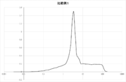
- the Log differential pore volume distribution obtained by the mercury intrusion method of the composite particles produced in Example 1 is shown.
- the Log differential pore volume distribution obtained by the mercury intrusion method of the composite particles produced in Example 2 is shown.
- the Log differential pore volume distribution obtained by the mercury intrusion method of the composite particles produced in Comparative Example 1 is shown.
- the Log differential pore volume distribution obtained by the mercury intrusion method of the composite particles produced in Comparative Example 2 is shown.
- the Log differential pore volume distribution obtained by the mercury intrusion method of the mixed negative electrode material of the composite particles produced in Examples 1 and 2 and Comparative Example 1 and the uncomposited spherical natural graphite is shown.
- the term "process” includes not only a process independent of other processes but also the process if the purpose of the process is achieved even if the process cannot be clearly distinguished from the other process. ..
- the numerical range indicated by using "-" in the present disclosure includes the numerical values before and after "-" as the minimum value and the maximum value, respectively.
- the upper limit value or the lower limit value described in one numerical range may be replaced with the upper limit value or the lower limit value of another numerical range described stepwise. ..
- the upper limit value or the lower limit value of the numerical range may be replaced with the value shown in the examples.
- each component may contain a plurality of applicable substances.
- the content or content of each component is the total content or content of the plurality of substances present in the composition unless otherwise specified.
- a plurality of types of particles corresponding to each component may be contained.
- the particle size of each component means a value for a mixture of the plurality of particles present in the composition unless otherwise specified.
- the term "layer" refers to the case where the layer is formed in the entire region when the region where the layer is present is observed, and also when the layer is formed only in a part of the region. included.
- the term “laminated” refers to stacking layers, and two or more layers may be bonded or the two or more layers may be removable.
- “(meth) acrylic” means at least one of acrylic and methacrylic
- "(meth) acrylate” means at least one of acrylate and methacrylate
- “(meth) acrylonitrile” means acrylonitrile and methacryllonitrile. Means at least one of nitriles.
- the description of the pore volume distribution (including the pore volume) and the particle size distribution (including the average particle size) of the specific composite particles described later contained in the negative electrode material is described in the specific composite contained in the negative electrode material. It means the pore volume distribution and particle size distribution when the entire particle is regarded as a set.
- the negative electrode material for a lithium ion secondary battery of the present disclosure includes composite particles containing a plurality of flat graphite particles assembled or bonded so that their orientation planes are non-parallel, and spherical graphite particles.
- the composite particles satisfy the following (1) and (2).
- the pore volume in the range of the pore diameter of 0.10 ⁇ m or more and 8.00 ⁇ m or less obtained by the mercury intrusion method is 0.20 mL / g or more and 1.00 mL / g or less.
- the specific composite particles contained in the negative electrode material for a lithium ion secondary battery of the present disclosure have a pore volume of 0.20 mL / g in a pore diameter range of 0.10 ⁇ m or more and 8.00 ⁇ m or less, which is obtained by a mercury injection method. It is 1.00 mL / g or less.
- the specific composite particles contained in the negative electrode material for a lithium ion secondary battery of the present disclosure have a pore diameter in the range of 0.10 ⁇ m or more and 8.00 ⁇ m or less in the Log differential pore volume distribution obtained by the mercury injection method. At least two peaks appear.
- Such specific composite particles maintain pores having a relatively high diameter at a constant ratio, and it is presumed that the electrolytic solution easily enters.
- the specific composite particle is not particularly limited as long as it is a composite particle containing a plurality of flat graphite particles assembled or bonded so that the orientation planes are non-parallel, and spherical graphite particles.
- a plurality of flat graphite particles may be assembled or bonded so that the orientation planes are non-parallel, and may be bonded to at least a part of the surface of the spherical graphite particles.
- the flat graphite particles may be bonded to at least a part of the surface of the spherical graphite particles via a carbon substance derived from a binder. Whether or not the specific composite particles are formed can be confirmed by, for example, observation with a scanning electron microscope (SEM).
- the specific composite particles include a plurality of flat graphite particles that are aggregated or bonded so that the orientation planes are non-parallel.
- the flat graphite particles have a non-spherical shape having a major axis and a minor axis. Examples thereof include graphite particles having a shape such as scaly, scaly, and partially lumpy. More specifically, the aspect ratio represented by A / B may be 1.2 to 5.0 when the length in the major axis direction is A and the length in the minor axis direction is B. It may be 1.3 to 3.0. The aspect ratio is obtained by enlarging the graphite particles with a microscope, arbitrarily selecting 100 graphite particles, measuring A / B, and taking the average value thereof.
- the orientation planes of the flat graphite particles are non-parallel to each other can be confirmed by observing micrographs.
- the state in which the flat graphite particles are aggregated or bonded may be a state in which two or more flat graphite particles are chemically aggregated or bonded via a carbon substance.
- the carbon substance may be, for example, a carbon substance in which a binder such as tar or pitch is carbonized in the firing step. From the viewpoint of mechanical strength, flat graphite particles may be bonded. Whether or not the flat graphite particles are aggregated or bonded can be confirmed by, for example, observation with a scanning electron microscope.
- the number of the flat graphite particles aggregated or bonded may be 3 or more, or 10 or more. Further, the number of the flat graphite particles aggregated or bonded may be one or less.
- the average particle size (D50) may be 50 ⁇ m or less, or 25 ⁇ m or less, from the viewpoint of ease of assembly or bonding.
- the average particle size (D50) may be 1 ⁇ m or more.
- the average particle size (D50) of the graphite particles can be measured by the same method as the measurement of the average particle size of the negative electrode material described later.
- the raw material of the flat graphite particles is not particularly limited, and examples thereof include artificial graphite, natural graphite, coke, resin, tar, and pitch.
- graphite obtained from artificial graphite, natural graphite or coke has high crystallinity and becomes soft particles, so that the density of the electrode tends to be easily increased when it is used as an electrode. Further, when graphite having a high crystallinity is used, the R value in the Raman measurement of the specific composite particle becomes small, and the initial charge / discharge efficiency tends to be improved.
- the specific composite particles include spherical graphite particles.
- the spherical graphite particles having a high density the density of the negative electrode material can be increased as compared with the case where only the flat graphite particles are contained, and the pressure applied during the densification treatment can be reduced. There is a tendency to be able to do it. As a result, it is considered that the phenomenon that the flat graphite particles are oriented in the direction parallel to the current collector and hinder the movement of lithium ions can be suppressed.
- the spherical graphite particles and their raw materials include spherical artificial graphite and spherical natural graphite.
- the spherical graphite particles may be high-density graphite particles.
- the spherical graphite particles may be spherical natural graphite that has been subjected to particle spheroidizing treatment to increase the tap density, or may be spherical graphite particles fired at 1500 ° C. or higher.
- the spherical graphite particles used as a raw material are fired at 1500 ° C. or higher, they become highly crystalline spherical graphite particles, and the R value of the specific composite particles can be reduced.
- the average particle size of the spherical graphite particles is not particularly limited, and may be 5 ⁇ m to 40 ⁇ m, 8 ⁇ m to 35 ⁇ m, or 10 ⁇ m to 30 ⁇ m.
- the average particle size can be measured by a laser diffraction particle size distribution measuring device, and is the particle size (D50) when the integration from the small diameter side is 50% in the volume-based particle size distribution. Specifically, it can be measured in the same manner as the measurement of the average particle size of the negative electrode material described later.
- the circularity of the spherical graphite particles is not particularly limited, and may be 0.80 or more, or 0.85 or more. Some of the spherical graphite particles are deformed by a mechanical force in the process of manufacturing the specific composite particles. However, the higher the overall circularity of the spherical graphite particles contained in the specific composite particles, the lower the orientation as the negative electrode material, and the better the characteristics as an electrode.
- As a method for increasing the circularity of the spherical graphite particles contained in the specific composite particles there is an example of using spherical graphite particles having a high circularity as a raw material. The circularity is measured for a portion of spherical graphite particles contained in the specific composite particle.
- the circularity of the spherical graphite particles can be obtained by taking a photograph of a cross section of the spherical graphite particles and using the following formula.
- Circularity (peripheral length of equivalent circle) / (peripheral length of cross-sectional image of spherical graphite particles)
- the "equivalent circle” is a circle having the same area as the cross-sectional image of the spherical graphite particles.
- the peripheral length of the cross-sectional image of the spherical graphite particles is the length of the contour line of the cross-sectional image of the spherical graphite particles imaged.
- the cross section of the spherical graphite particles is magnified 1000 times with a scanning electron microscope, 10 spherical graphite particles are arbitrarily selected, and the individual spherical graphite particles are subjected to the above method. It is a value obtained by measuring the circularity and taking the average thereof.
- a sample electrode or an electrode to be observed is embedded in an epoxy resin and then mirror-polished. Then, a method of observing the electrode cross section with a scanning electron microscope, a method of preparing an electrode cross section using an ion milling device (for example, E-3500, manufactured by Hitachi High Technology Co., Ltd.) and observing with a scanning electron microscope, etc. Can be mentioned.
- an ion milling device for example, E-3500, manufactured by Hitachi High Technology Co., Ltd.
- the sample electrode can be manufactured in the same manner as the sample electrode used for measuring the average particle size described later, for example.
- the average particle size (median diameter) of the specific composite particles is not particularly limited. From the viewpoint of the influence on the orientation and the permeability of the electrolytic solution, it may be 10 ⁇ m to 30 ⁇ m or 15 ⁇ m to 25 ⁇ m.
- the average particle size can be measured by a laser diffraction particle size distribution measuring device, and is the particle size (D50) when the integration from the small diameter side is 50% in the volume-based particle size distribution.
- the average particle size can be measured using a laser diffraction particle size distribution measuring device (for example, SALD-3000J, manufactured by Shimadzu Corporation) under the following conditions. Absorbance: 0.05 to 0.20 Sonication: 0.5-3 minutes
- the method for measuring the average particle size of the specific composite particles is to embed the sample electrode or the electrode to be observed in the epoxy resin and then mirror polish it. Then, a method of observing the electrode cross section with a scanning electron microscope, a method of preparing an electrode cross section using an ion milling device (for example, E-3500, manufactured by Hitachi High Technology Co., Ltd.) and observing with a scanning electron microscope, etc. Can be mentioned.
- the average particle size in this case is the median value of the particle size of 100 arbitrarily selected specific composite particles.
- the sample electrode is prepared by using, for example, a mixture of 98 parts by mass of a negative electrode material for a lithium ion secondary battery, 1 part by mass of styrene-butadiene resin as a binder, and 1 part by mass of carboxymethyl cellulose as a thickener as a solid content. Water is added so that the viscosity at 25 ° C. is 1500 mPa ⁇ s to 2500 mPa ⁇ s to prepare a dispersion, and the dispersion is spread on a copper foil having a thickness of 10 ⁇ m to a thickness of about 70 ⁇ m (at the time of coating). After coating, it can be produced by drying at 120 ° C. for 1 hour.
- the R value measured by Raman is preferably 0.03 or more and 0.10 or less.
- the R value may be 0.04 or more and 0.10 or less, or 0.05 or more and 0.10 or less.
- the R value is 0.10 or less, the decomposition reaction of the electrolytic solution can be suppressed, and the generation of gas swelling of the lithium ion secondary battery and the decrease in the initial efficiency tend to be suppressed.
- the electrode can be suitably applied to high-density electrodes.
- the R value is 0.03 or more, the graphite lattice defects for inserting and removing lithium ions are sufficiently maintained, and the charge / discharge load characteristics tend to be well maintained.
- the R value in Raman spectrum obtained in Raman measurements to be described later define the intensity IA of a maximum peak in the vicinity of 1580 cm -1, the intensity ratio of the intensity IB of a maximum peak around 1360 cm -1 and (IB / IA) ..
- Raman measurement is obtained by applying and pressurizing a specific composite particle or a specific composite particle to a current collector, for example, using a Raman spectroscope "Laser Raman spectrophotometer (model number: NRS-1000, manufactured by JASCO Corporation)".
- the electrodes can be set on the sample plate so as to be flat, and the negative electrode material for the lithium ion secondary battery can be irradiated with semiconductor laser light for measurement.
- the measurement conditions are as follows. Wavelength of semiconductor laser light: 532 nm Wavenumber resolution: 2.56 cm -1 Measuring range: 1180 cm -1 to 1730 cm -1 Peak Research: Background Removal
- the ratio of the residual carbon content derived from the binder component such as pitch used as a raw material may be 30% by mass or less of the entire specific composite particles.
- a component with low crystallinity, such as a binder component is used to collect or combine the above-mentioned flat graphite particles to form composite particles, but the development of crystallinity due to graphitization is unlikely to occur and the residual carbon content is also high. Low.
- the pore volume in the range of 0.10 ⁇ m or more and 8.00 ⁇ m or less, which is obtained by the mercury injection method, is 0.20 mL / g. It is 1.00 mL / g or less.
- the pore volume represents the integrated pore volume in the range of the pore diameter of 0.10 ⁇ m or more and 8.00 ⁇ m or less.
- the injection rate of the electrolytic solution which is the moving medium of lithium ions, becomes high when the lithium ion secondary battery is used, and good high-speed charge / discharge characteristics are obtained. Tends to be obtained. Further, when the pore volume is 1.00 mL / g or less, the oil absorption capacity of additives such as organic binders and thickeners can be suppressed, and the viscosity of the negative electrode material slurry can be easily controlled. , There is a tendency that the adhesive force to the current collector can be kept good.
- the pore volume in the range of the pore diameter of 0.10 ⁇ m or more and 8.00 ⁇ m or less obtained by the mercury injection method may be 0.40 mL / g or more and 0.80 mL / g or less. , 0.50 mL / g or more and 0.80 mL / g or less.
- the pore volume is preferably 0.50 mL / g or more and 1.00 mL / g or less, preferably 0.60 mL / g. More preferably, it is 1.00 mL / g or less.
- the pore volume of the specific composite particles can be set within the above range, for example, by appropriately adjusting the blending ratio of the spherical graphite particles.
- the mercury press-fitting method is performed using, for example, "pore distribution measuring device Autopore 9520 type, manufactured by Shimadzu Corporation".
- the mercury parameters are set to a mercury contact angle of 130.0 ° and a mercury surface tension of 485.0 mN / m (485.0 days / cm).
- a sample (about 0.3 g) is taken in a standard cell and measured under the condition of an initial pressure of 9 kPa (about 1.3 psia, equivalent to a pore diameter of about 140 ⁇ m). From the obtained pore distribution, the volume of the pore volume in the range of 0.10 ⁇ m or more and 8.00 ⁇ m or less is calculated.
- the first peak P1 and the first peak P1 in the range of the pore diameter of 0.10 ⁇ m or more and 8.00 ⁇ m or less in the Log differential pore volume distribution obtained by the mercury intrusion method. Two peaks of the second peak P2 on the higher diameter side appear. It was found that having at least two peaks in the Log differential pore volume distribution is excellent in liquid injection property when used as a negative electrode.
- the first peak P1 and the second peak are defined as follows. Two peaks are selected from those having a large peak intensity in the above pore diameter range, and the peak existing on the short diameter side (that is, the peak existing on the smaller diameter side) is set as the first peak P1 and is high. The peak existing on the diameter side (that is, the peak existing on the larger diameter side) is referred to as the second peak P2. In the negative electrode material for a lithium secondary battery of the present disclosure, three or more peaks may be present in the pore diameter range, and it is preferable that only two peaks are present.
- the pore diameter when the Log differential pore volume of the first peak P1 is maximized is 0.10 ⁇ m or more and less than 4.00 ⁇ m, and the Log differential pore volume of the second peak P2 is maximum.
- the pore diameter at the time is 4.00 ⁇ m or more and 8.00 ⁇ m or less.
- the pore diameter when the Log differential pore volume of the first peak P1 is maximized is 1.00 ⁇ m or more and less than 4.00 ⁇ m
- the Log differential pore volume of the second peak P2 is The maximum pore diameter is 4.00 ⁇ m or more and 7.00 ⁇ m or less.
- the pore diameter when the Log differential pore volume of the first peak P1 is maximized is 1.50 ⁇ m or more and less than 3.50 ⁇ m
- the Log differential pore volume of the second peak P2 is The maximum pore diameter is 4.50 ⁇ m or more and 6.50 ⁇ m or less.
- the difference between the pore diameter when the Log differential pore volume of the first peak P1 is maximized and the pore diameter when the Log differential pore volume of the second peak P2 is maximized is particularly limited. Not done.
- the difference in pore diameter may be 0.50 ⁇ m to 5.00 ⁇ m, 1.00 ⁇ m to 4.00 ⁇ m, or 2.00 ⁇ m to 3.00 ⁇ m.
- the Log differential pore volume distribution of the specific composite particle has a peak.
- the peak occurs when the slope changes from positive to negative. Judged to have. However, the line assuming that the peak does not exist, that is, the peak whose vertical height from the background is less than 0.1 cm 3 / g is not judged to be a peak.
- the intensity ratio of the two peaks is not particularly limited, and is 4.0 or less from the viewpoint of further improving the liquid injection property. It is preferable that it is 3.8 or less. From the viewpoint of increasing the surface area for insertion and desorption of lithium ions, it is preferably 0.5 or more, more preferably 1.0 or more, and even more preferably 2.0 or more.
- the peak intensity ratio can be obtained as the ratio of the peak areas of the Log differential pore volume distribution using the above-mentioned pore distribution measuring device.
- a specific composite particle in which two peaks of a certain second peak P2 appear is not particularly limited.
- a negative electrode material having at least two peaks may be obtained by adjusting the composition of the raw materials used when producing the specific composite particles to adjust the degree of graphitization. More specifically, the specific composite particles having at least two peaks are described by keeping the state of relatively high hardness without proceeding with graphitization too much by, for example, reducing the blending amount of the graphitization catalyst. Easy to get.
- the specific composite particles having at least two peaks may be obtained by adjusting the blending ratio of the spherical graphite particles which are the raw materials of the specific composite particles and the degree of graphitization of the other raw materials. .. Further, by not performing the isotropic pressure treatment described later on the graphite formed by firing and crushing, it is difficult for the pore size to become uniform, and it is easy to obtain the specific composite particles having at least two peaks.
- the specific surface area of the specific composite particles as measured by the BET method may be 1.5 m 2 / g or more and 6.0 m 2 / g or less, and 2.5 m 2 / g or more and 5.0 m 2 / g or less. There may be.
- the specific surface area is an index indicating the area of the interface with the electrolytic solution. When the value of the specific surface area is 6.0 m 2 / g or less, the area of the interface between the specific composite particles and the electrolytic solution is not too large, the increase in the reaction field of the decomposition reaction of the electrolytic solution is suppressed, and the gas generation is suppressed. In addition, the initial charge / discharge efficiency may be good.
- the value of the specific surface area is 1.5 m 2 / g or more, the current density per unit area does not rise sharply and the load is suppressed, so that charge / discharge efficiency, charge acceptability, rapid charge / discharge characteristics, etc. Tends to be good.
- the specific surface area can be measured by a known method such as the BET method (nitrogen gas adsorption method).
- the specific composite particles or the electrodes obtained by applying and pressurizing the specific composite particles to the current collector are filled in the measurement cell, and the sample obtained by performing pretreatment by heating at 200 ° C. while vacuum degassing is subjected to gas.
- Nitrogen gas is adsorbed using an adsorption device (for example, ASAP2010, manufactured by Shimadzu Corporation).
- BET analysis is performed on the obtained sample by the 5-point method, and the specific surface area is calculated.
- the specific surface area of the specific composite particles can be set in the above range by adjusting the average particle size, for example. Decreasing the average particle size tends to increase the specific surface area, and increasing the average particle size tends to decrease the specific surface area.
- Specific composite particles is preferably saturated tapping density is not more than 0.60 g / cm 3 or more 0.90 g / cm 3, more preferably at most 0.60 g / cm 3 or more 0.80 g / cm 3, More preferably, it is 0.65 g / cm 3 or more and 0.70 g / cm 3 or less. Saturated tapping density may be less than 0.60 g / cm 3 or more 0.80 g / cm 3, it may be 0.60 g / cm 3 or more 0.70 g / cm less than 3.
- the saturated tap density is an index of increasing the density of the electrode.
- the saturation tap density of the specific composite particles is 0.60 g / cm 3 or more
- the electrode obtained by applying the negative electrode material for a lithium ion secondary battery containing the specific composite particles on the current collector becomes dense.
- the pressure applied to adjust the electrode density can be reduced, and the graphite particles in the electrode can easily maintain their original shape. If the graphite particles can maintain their original shape, there are advantages such as small orientation of the electrode plate, easy entry and exit of lithium ions, and improvement of cycle characteristics.
- the saturated tap density of the specific composite particle When the saturated tap density of the specific composite particle is 0.90 g / cm 3 or less, a sufficient pore volume is maintained, and a sufficient amount of an electrolytic solution that serves as a transfer medium for lithium ions when used as a battery is to be secured. It tends to be possible to obtain good high-speed charge / discharge characteristics.
- the proportion of spherical graphite particles is adjusted appropriately (the tap density tends to increase when the proportion of spherical graphite particles is increased, and the tap density tends to decrease when the proportion is decreased). By doing so, the above range can be obtained.
- the saturated tap density can be measured by a known method.
- a filling density measuring device for example, KRS-406, manufactured by Kuramochi Kagaku Kikai Seisakusho Co., Ltd.
- 100 ml of specific composite particles are placed in a graduated cylinder, and tapped (the graduated cylinder from a predetermined height) until the density is saturated. Drop it) to calculate.
- the pellet density of the specific composite particles is not particularly limited.
- the pellet density of the specific composite particles is preferably 1.77 g / cm 3 or less.
- the hardness of the specific composite particles is not too low, so that the pore volume and at least two peaks tend to be suitable.
- the press pressure is applied to increase the electrode density, the amount of interparticle voids tends to be less likely to decrease due to the deformation of the specific composite particles. As a result, the state in which the electrolytic solution easily permeates the entire negative electrode material layer is easily maintained, and the liquid injection property tends to be further improved.
- pellet density of the specific composite particles 0.50 g of the specific composite particles is put into a tablet molding machine (tablet bottom area: 1.327 cm 2 ), and the volume density of the tablet after applying a pressure of 1 ton for 30 seconds is determined. Obtained at.
- the negative electrode material for a lithium ion secondary battery of the present disclosure is a negative electrode material other than specific composite particles (flat graphite particles without composite particles, spherical graphite particles without composite particles, flat graphite particles). May be mixed with (such as massive graphite particles formed by a plurality of aggregates or bonds) and used for producing a negative electrode.
- a negative electrode material for a lithium ion secondary battery formed by mixing a specific composite particle and a negative electrode material other than the specific composite particle is also referred to as a mixed negative electrode material.
- the negative electrode material for a lithium ion secondary battery is any one or more selected from the group consisting of natural graphite, artificial graphite, amorphous coated graphite, resin coated graphite, amorphous carbon, and occluded metal particles. It may be a mixture of a lithium ion occlusion structure and the above-mentioned specific composite particles.
- the ratio of the specific composite particles to the entire negative electrode material of the lithium ion secondary battery may be 20% by mass or more, and 30% by mass or more. It may be 40% by mass or more, and may be 50% by mass or more. From the viewpoint of reducing the cost of producing the negative electrode, the ratio of the specific composite particles to the entire mixed negative electrode material may be 70% by mass or less, 60% by mass or less, or 50% by mass or less. It may be.
- the negative electrode material of the lithium ion secondary battery of the present disclosure is a mixed negative electrode material
- the negative electrode material for the lithium ion secondary battery may further contain uncomposited spherical natural graphite in addition to the specific composite particles.
- the compounding ratio is not particularly limited. For example, it may be blended so that the content of the uncomposited spherical natural graphite is 30% by mass or more with respect to the total amount of the specific composite particles and the uncomposited spherical natural graphite. It may be blended so as to be 50% by mass or more, and may be blended so that it may be 50% by mass or more.
- the content of the uncomposited spherical natural graphite is 30% by mass or more, it is preferable from the viewpoint that the cost of producing the negative electrode can be suppressed. Further, from the viewpoint of obtaining good charge / discharge characteristics, the content of the uncomposited spherical natural graphite is 80% by mass or less with respect to the total amount of the specific composite particles and the uncomposited spherical natural graphite. It may be.
- the negative electrode material for a lithium ion secondary battery of the present disclosure tends to have an appropriate pore volume distribution even when a specific composite particle and uncomposited natural graphite particles are mixed to form a mixed negative electrode material. It was issued. In particular, when a relatively large amount of uncomposited spherical natural graphite is blended, for example, 30 uncomposited spherical natural graphite is added to the total amount of the specific composite particles and the uncomposited spherical natural graphite. It was found that even when the mixture is blended in an amount of mass% or more, an appropriate pore volume distribution can be easily obtained, and a lithium ion secondary battery having excellent charge / discharge characteristics can be easily obtained.
- the negative electrode material for a lithium ion secondary battery is a mixed negative electrode material in which a specific composite particle and a negative electrode material other than the specific composite particle are mixed
- the number of peaks in the Log differential pore volume distribution obtained by the mercury injection method. May be one.
- the pore diameter when the Log differential pore volume is maximized is not particularly limited, and may be, for example, 2.00 ⁇ m to 7.00 ⁇ m or 3.00 ⁇ m to 6.00 ⁇ m.
- the method for producing a negative electrode material for a lithium ion secondary battery obtains a mixture containing a graphitizable aggregate, a graphitizable binder, a graphitization catalyst, and spherical graphite particles. It includes producing specific composite particles by a method including (referred to as step (a)) and firing the mixture (referred to as step (b)).
- the specific composite particles can be produced by the method including the steps (a) and (b), and therefore, the above-mentioned negative electrode material for a lithium ion secondary battery of the present disclosure can be produced by the above method.
- the above method when the raw material is graphitized by firing, heavy metals, magnetic foreign substances and impurities contained in the raw material are removed by high heat. No need to do. As a result, there is a tendency that the manufacturing cost can be reduced and a highly safe negative electrode material for a lithium ion secondary battery can be provided.
- spherical graphite particles that are already graphite may be used in addition to the graphitizable aggregate.
- spherical graphite particles are also calcined together with other raw materials.
- the R value of the Raman measurement of the specific composite particles can be lowered as compared with the case where the spherical graphite particles are mixed with those obtained by calcining and graphitizing other raw materials.
- a graphitizable aggregate, a graphitizable binder, a graphitizing catalyst, and spherical graphite particles are mixed to obtain a mixture.
- the graphitizable aggregate include coke such as fluid coke, needle coke, and mosaic coke.
- the graphitizable aggregate is not particularly limited as long as it is in powder form. Among them, coke powder that is easily graphitized such as needle coke may be used.
- the graphite is not particularly limited as long as it is a powder.
- the particle size of the graphitizable aggregate is preferably smaller than the particle size of the flat graphite particles.
- Examples of the spherical graphite particles include spherical artificial graphite and spherical natural graphite. As the spherical graphite particles, the details of the spherical graphite particles contained in the above-mentioned specific composite particles can be applied.
- Examples of the graphitizable binder include coal-based, petroleum-based, artificial pitch and tar, thermoplastic resins, thermosetting resins, and the like.
- Examples of the graphitizing catalyst include substances having a graphitizing catalytic action such as silicon, iron, nickel, titanium and boron, carbides, oxides and nitrides of these substances.
- the content of the spherical graphite particles may be 5% by mass to 80% by mass, 8% by mass to 75% by mass, or 8% by mass, based on 100 parts by mass of the graphitizable aggregate. It may be from 10% by mass to 70% by mass, from 10% by mass to 30% by mass, or from 11% by mass to 19% by mass.
- a high density and a high charge / discharge capacity tend to be obtained.
- specific composite particles having a pore volume and at least two peaks tend to be preferably obtained.
- the content of the graphitizable binder may be 5% by mass to 80% by mass or 10% by mass to 80% by mass with respect to 100 parts by mass of the graphitizable aggregate. It may be 15% by mass to 80% by mass.
- the content of the graphitizing catalyst is not particularly limited. For example, it is preferable to add 1 part by mass to 50 parts by mass of the graphitizing catalyst with respect to 100 parts by mass of the total amount of the graphitizable aggregate and the graphitizable binder.
- the amount of the graphitizing catalyst is 1 part by mass or more, the crystal development of the graphitized particles is good, and the charge / discharge capacity tends to be good.
- the amount of the graphitizing catalyst is 50 parts by mass or less, the graphitizable aggregate, the graphitizable binder, the graphitizing catalyst and the spherical graphite particles can be mixed more uniformly, and the work can be performed. It tends to be good.
- the content of the graphitizing catalyst is more preferably 30 parts by mass or less, more preferably 25 parts by mass or less, based on 100 parts by mass of the total amount of the graphitizable aggregate and the graphitizable binder. It is more preferably 20 parts by mass or less.
- the content of the graphitizing catalyst is more preferably 5 parts by mass or more with respect to 100 parts by mass of the total amount of the graphitizable aggregate and the graphitizable binder, and is 10 parts by mass or more.
- the amount is 15 parts by mass or more.
- the content of the graphitization catalyst is in the above range, the pore volume and at least two peaks of the specific composite particles tend to be suitably obtained.
- the development of crystals of graphitic particles is good, and the charge / discharge capacity tends to be good.
- the content of the graphitizing catalyst may be 13% by mass to 25% by mass with respect to 100 parts by mass of the total amount of the graphitizable aggregate and the graphitizable binder. It may be 15% by mass to 20% by mass.
- the mixing method of the graphitizing catalyst is not particularly limited, and any mixing method may be used as long as the graphitizing catalyst is present inside the particles or on the surface of the particles in the mixture at least before firing for graphitization.
- the method of mixing the graphitizable aggregate, the graphitizable binder, the graphitizing catalyst, and the spherical graphite particles can be performed using a kneader or the like.
- the mixing may be performed at a temperature equal to or higher than the softening point of the binder.
- the binder capable of graphitizing is pitch, tar, etc.
- the temperature may be 50 ° C. to 300 ° C.
- the binder is a thermosetting resin
- the temperature may be 20 ° C. to 100 ° C. Good.
- the mixture obtained in the step (a) is calcined.
- the graphitizable components in the mixture are graphitized.
- the firing is preferably performed in an atmosphere in which the mixture is difficult to oxidize, and examples thereof include a method of firing in a nitrogen atmosphere, argon gas, or vacuum.
- the firing temperature is not particularly limited as long as the graphitizable component can be graphitized. For example, it may be 1500 ° C. or higher, 2000 ° C. or higher, 2500 ° C. or higher, or 2800 ° C. or higher.
- the firing temperature may be 3200 ° C. or lower. When the firing temperature is 1500 ° C. or higher, crystal changes occur. When the firing temperature is 2000 ° C.
- the specific composite particles are produced by molding the mixture between the step (a) and the step (b) (step (c)). ) And heat treatment of the mixture (referred to as step (d)). Specifically, whether only the step (b) is performed after the step (a) or only the step (c) is performed after the step (a), the step (b) and the step (b) and the step (b) are performed after the step (a). C) may be performed in this order, or steps (c) and (b) may be performed in this order after the step (a).
- the molding in the step (c) of molding the mixture can be performed, for example, by crushing the mixture and placing it in a container such as a mold.
- the heat treatment may be performed at 1500 ° C. or higher, or may be performed at 2500 ° C. or higher.
- the graphitized product obtained after firing may be pulverized to obtain a desired average particle size.
- the mixture may be molded and pulverized before firing to adjust the particle size, and the graphitized product obtained after firing may be further pulverized.
- the method for pulverizing the graphitized product is not particularly limited. For example, it can be carried out by a known method using a jet mill, a vibration mill, a pin mill, a hammer mill or the like.
- the average particle size (median diameter) after pulverization may be 100 ⁇ m or less, or 10 ⁇ m to 50 ⁇ m.
- the graphitized product after firing and crushing may be subjected to an isotropic pressure treatment.
- an isotropic pressure treatment for example, a method of filling a container made of rubber or the like with graphite after firing and crushing, sealing the container, and then performing the isotropic pressure treatment with a press machine. Can be mentioned. It is preferable that the graphite product that has been subjected to the isotropic pressure treatment is crushed by a cutter mill or the like and sized by a sieve or the like.
- the pore volume in the range of 0.10 ⁇ m or more and 8.00 ⁇ m or less obtained by the mercury intrusion method is 0.20 mL / g or more and 1.00 mL / g or less, and the Log differential fineness obtained by the mercury intrusion method
- the pore volume distribution at least two peaks P1 and a second peak P2 on the higher diameter side than the first peak P1 in the range where the pore diameter is 0.10 ⁇ m or more and 8.00 ⁇ m or less.
- the above method is an example of a method for producing specific composite particles.
- Specific composite particles may be produced by a method other than the above.
- As a method other than the above after producing graphite particles (lumpy graphite particles) formed by assembling or bonding a plurality of flat graphite particles so that the orientation planes are non-parallel, spherical graphite particles are mixed. Examples include a method of forming composite particles.
- the description of Japanese Patent No. 3285520, Japanese Patent No. 332502, etc. can be referred to.
- the negative electrode material slurry for a lithium ion secondary battery in one embodiment of the present disclosure is a lithium ion secondary battery manufactured by the method for manufacturing the negative electrode material for a lithium ion secondary battery or the negative electrode material for a lithium ion secondary battery. Includes a negative electrode material for use, an organic binder, and a solvent.
- organic binder there are no particular restrictions on the organic binder.
- styrene-butadiene rubber ethylenically unsaturated carboxylic acid ester (methyl (meth) acrylate, ethyl (meth) acrylate, butyl (meth) acrylate, hydroxyethyl (meth) acrylate, etc.), (meth) acrylonitrile, ethylenically non-ethylate.
- (Meta) acrylic copolymers derived from saturated carboxylic acids acrylic acid, methacrylic acid, itaconic acid, fumaric acid, maleic acid, etc.
- polyfluorinated vinylidene polyethylene oxide, polyepichlorohydrin, polyphosphazene, poly Examples thereof include polymer compounds such as acrylonitrile, polyimide, and polyamideimide.
- the solvent is not particularly limited.
- N-methylpyrrolidone dimethylacetamide
- Organic solvents such as dimethylformamide and ⁇ -butyrolactone are used.
- the negative electrode material slurry for a lithium ion secondary battery may contain a thickener for adjusting the viscosity, if necessary.
- a thickener for adjusting the viscosity, if necessary.
- the thickener include carboxymethyl cellulose, methyl cellulose, hydroxymethyl cellulose, ethyl cellulose, polyvinyl alcohol, polyacrylic acid and salts thereof, oxidized starch, phosphorylated starch, casein and the like.
- the negative electrode material slurry for the lithium ion secondary battery may be mixed with a conductive auxiliary agent, if necessary.
- a conductive auxiliary agent include carbon black, graphite, acetylene black, oxides exhibiting conductivity, nitrides exhibiting conductivity, and the like.
- the negative electrode for a lithium ion secondary battery in one embodiment of the present disclosure includes a current collector and a negative electrode material for the lithium ion secondary battery or a negative electrode material for the lithium ion secondary battery formed on the current collector. It has a negative electrode material layer including a negative electrode material for a lithium ion secondary battery produced by the method.
- the material and shape of the current collector are not particularly limited.
- a material such as a strip-shaped foil made of a metal or alloy such as aluminum, copper, nickel, titanium, or stainless steel, a strip-shaped drilling foil, or a strip-shaped mesh may be used.
- a porous material such as porous metal (foam metal) or carbon paper may be used.
- the method of forming the negative electrode material layer including the negative electrode material for the lithium ion secondary battery on the current collector is not particularly limited. For example, it can be performed by a known method such as a metal mask printing method, an electrostatic coating method, a dip coating method, a spray coating method, a roll coating method, a doctor blade method, a gravure coating method, and a screen printing method.
- a known method such as a roll, a press, or a combination thereof can be used.
- the negative electrode for a lithium ion secondary battery obtained by forming the negative electrode material layer on a current collector may be heat-treated depending on the type of organic binder used.
- the solvent is removed by the heat treatment, the strength is increased by curing the binder, and the adhesion between the particles and between the particles and the current collector tends to be improved.
- the heat treatment may be carried out in an inert atmosphere such as helium, argon or nitrogen or in a vacuum atmosphere in order to prevent oxidation of the current collector during the treatment.
- the negative electrode for the lithium ion secondary battery Before performing the heat treatment, the negative electrode for the lithium ion secondary battery may be pressed (pressurized).
- the electrode density can be adjusted by the pressure treatment.
- the electrode density may be 1.5g / cm 3 ⁇ 1.9g / cm 3, may be 1.6g / cm 3 ⁇ 1.8g / cm 3.
- the lithium ion secondary battery according to the embodiment of the present disclosure includes a positive electrode, an electrolyte, and a negative electrode for the lithium ion secondary battery.
- the lithium ion secondary battery may be configured such that, for example, the negative electrode and the positive electrode are arranged so as to face each other via a separator, and an electrolytic solution containing an electrolyte is injected.
- the positive electrode can be obtained by forming a positive electrode layer on the surface of the current collector in the same manner as the negative electrode.
- a material such as a band-shaped foil made of a metal or alloy such as aluminum, titanium, or stainless steel, a band-shaped perforated foil, or a band-shaped mesh can be used.
- the positive electrode material used for the positive electrode layer is not particularly limited.
- metal compounds capable of doping or intercalating lithium ions, metal oxides, metal sulfides, and conductive polymer materials can be mentioned.
- lithium cobaltate (LiCoO 2), lithium nickelate (LiNiO 2), lithium manganate (LiMnO 2), and these mixed oxide (LiCo x Ni y Mn z O 2, x + y + z 1,0 ⁇ x , 0 ⁇ y; LiNi 2-x Mn x O 4 , 0 ⁇ x ⁇ 2), lithium manganese spinel (LiMn 2 O 4 ), lithium vanadium compound, V 2 O 5 , V 6 O 13 , VO 2 , Mn O 2 , TiO 2 , MoV 2 O 8 , TiS 2 , V 2 S 5 , VS 2 , MoS 2 , MoS 3 , Cr 3 O 8 , Cr 2 O 5 , Olivin type LiMPO 4 (
- the separator examples include non-woven fabrics containing polyolefins such as polyethylene and polypropylene as main components, cloths, micropore films, and combinations thereof. If the lithium ion secondary battery has a structure in which the positive electrode and the negative electrode do not come into contact with each other, the separator may not be used.
- electrolyte examples include electrolytes such as lithium salts such as LiClO 4 , LiPF 6 , LiAsF 6 , LiBF 4 , LiSO 3 CF 3 , ethylene carbonate, propylene carbonate, butylene carbonate, vinylene carbonate, fluoroethylene carbonate, and cyclopentanone.
- lithium salts such as LiClO 4 , LiPF 6 , LiAsF 6 , LiBF 4 , LiSO 3 CF 3
- ethylene carbonate propylene carbonate, butylene carbonate, vinylene carbonate, fluoroethylene carbonate, and cyclopentanone.
- the electrolytic solution containing fluoroethylene carbonate tends to form a stable SEI (solid electrolyte interface) on the surface of the negative electrode material, and is suitable from the viewpoint of remarkably improving the cycle characteristics.
- at least one selected from the group consisting of ethylene carbonate, ethyl methyl carbonate, and vinylene carbonate is also preferably used.
- the form of the lithium ion secondary battery disclosed in the present disclosure is not particularly limited, and examples thereof include a paper type battery, a button type battery, a coin type battery, a laminated type battery, a cylindrical type battery, and a square type battery.
- the negative electrode material for a lithium ion secondary battery can be applied to all electrochemical devices such as hybrid capacitors having a charging / discharging mechanism of inserting and removing lithium ions in addition to the lithium ion secondary battery.
- Example 1 [1] 70 parts by mass of coke powder having an average particle size of 20 ⁇ m and 30 parts by mass of tar pitch were mixed and stirred at 100 ° C. for 1 hour to obtain a mixture. The mixture was then ground to 25 ⁇ m. 69 parts by mass of this crushed mixture powder, 13 parts by mass of silicon carbide, and 18 parts by mass of spherical natural graphite (circularity 0.92) were mixed, and the obtained mixed powder was placed in a mold and molded into a rectangular parallelepiped. The obtained rectangular parallelepiped was heat-treated at 1000 ° C. in a nitrogen atmosphere and then calcined at 2800 ° C. to graphitize the graphitizable component.
- the obtained graphite molded product was pulverized so that the average particle size was 20 ⁇ m to obtain graphite powder (specific composite particles).
- Average particle size, R value, pore volume and Log differential pore volume distribution of the graphite powder (specific composite particles) obtained above (diameters of the first peak P1 and the second peak P2, and their intensity ratios). ), Specific surface area, saturated tap density, and pellet density were evaluated. Each measurement was carried out by the method described above.
- the parts were kneaded to prepare a slurry.
- This slurry is applied to a current collector (copper foil having a thickness of 10 ⁇ m), dried in the air at 110 ° C. for 1 hour, and the coated substance (active substance) has an electrode density of 1.70 g / cm 3 by a roll press.
- a negative electrode for a lithium ion secondary battery was manufactured by integrating under the conditions.
- the liquid injection property of the negative electrode for the lithium ion secondary battery was measured by the method shown below.
- the negative electrode for the lithium ion secondary battery created above is punched out in a circular shape, and a PC (polycarbonate: manufactured by Kishida Chemical Co., Ltd.) is dropped 1 ⁇ m from the center of the negative electrode for the lithium ion secondary battery using a micropipette until it penetrates. The injection time was measured.
- a PC polycarbonate: manufactured by Kishida Chemical Co., Ltd.
- a 2016 type coin cell was prepared using a mixed solution, a polyethylene micropore membrane having a thickness of 25 ⁇ m as a separator, and a copper plate having a thickness of 230 ⁇ m as a spacer.
- the specific composite particles produced in the examples are mixed and mixed with uncomposited spherical natural graphite (average particle size 22 ⁇ m) at a ratio of 5: 5 (specific composite particles: spherical natural graphite, mass ratio).
- a negative electrode material was produced.
- For the mixed negative electrode material a Log differential pore volume distribution was obtained by the mercury press-fitting method under the above-mentioned conditions.
- Example 2 (1) 40 parts by mass of coke powder having an average particle size of 20 ⁇ m, 30 parts by mass of tar pitch, 13 parts by mass of silicon carbide, 14 parts by mass of spherical natural graphite, and 2 parts by mass of stearic acid are mixed and stirred at 100 ° C. for 1 hour. A mixture was obtained. The obtained mixed powder was molded by extrusion molding. The obtained cylinder was heat-treated at 1000 ° C. in a nitrogen atmosphere and then calcined at 2800 ° C. to graphitize the graphitizable component. The obtained graphite molded product was pulverized so that the average particle size was 19 ⁇ m to obtain the graphite powder (specific composite particles) of Example 2. A negative electrode for a lithium ion secondary battery and a lithium ion secondary battery were produced in the same manner as in Example 1, and evaluated in the same manner as in Example 1.
- the obtained graphite molded product was pulverized so that the average particle size was 24 ⁇ m to obtain a graphite powder.
- the obtained graphite powder was filled in a rubber container and sealed, and then the rubber container was subjected to isotropic pressure treatment at a pressure of 9800 N / cm 2 (1000 kgf / cm 2) with a press machine. Next, the graphite powder was crushed with a cutter mill and granulated with a sieve to obtain the graphite powder (specific composite particles) of Comparative Example 1.
- a negative electrode for a lithium ion secondary battery and a lithium ion secondary battery were produced in the same manner as in Example 1, and evaluated in the same manner as in Example 1.
- Example 2 The graphite powder (specific composite particles) obtained in Example 2 is filled in a rubber container, sealed, and then pressed against the rubber container at a pressure of 9800 N / cm 2 (1000 kgf / cm 2 ). A square pressurization treatment was performed. Next, the graphite powder was crushed with a cutter mill and granulated with a sieve to obtain the graphite powder (specific composite particles) of Comparative Example 2. A negative electrode for a lithium ion secondary battery and a lithium ion secondary battery were produced in the same manner as in Example 1, and evaluated in the same manner as in Example 1.
- Table 1 shows the evaluation results of Examples and Comparative Examples. Further, the Log differential pore volume distributions of the specific composite particles produced in each Example and Comparative Example are shown in FIGS. 1A to 1D. Further, FIG. 2 shows the Log differential pore volume distribution of the mixed negative electrode material of the specific composite particles of Examples 1 and 2 and Comparative Example 1 and spherical natural graphite.
- the P1 diameter and the P2 diameter are the first peak P1 in the range of 0.10 ⁇ m or more and 8.00 ⁇ m or less in the Log differential pore volume distribution of the specific composite particle, and the second peak if present, respectively. Represents the pore diameter at the maximum Log differential pore volume in P2. When there was one peak in the above range, the peak was classified as P1.
- the vertical axis represents the Log differential pore volume (cm 3 / g) and the horizontal axis represents the pore diameter ( ⁇ m).
- the graphite powders obtained in Examples and Comparative Examples are composite particles containing a plurality of flat graphite particles assembled or bonded so that their orientation planes are non-parallel, and spherical graphite particles. was confirmed by observation with a scanning electron microscope (SEM).
- the negative electrode for the lithium ion secondary battery produced in the example had improved liquid injection property.
Landscapes
- Chemical & Material Sciences (AREA)
- Chemical Kinetics & Catalysis (AREA)
- Electrochemistry (AREA)
- General Chemical & Material Sciences (AREA)
- Engineering & Computer Science (AREA)
- Manufacturing & Machinery (AREA)
- Materials Engineering (AREA)
- Inorganic Chemistry (AREA)
- Composite Materials (AREA)
- Battery Electrode And Active Subsutance (AREA)
Abstract
Description
(1)水銀圧入法により得られる、細孔直径0.10μm以上8.00μm以下の範囲における細孔容積が、0.20mL/g以上1.00mL/g以下である。
(2)水銀圧入法により得られるLog微分細孔容積分布にて、細孔直径が0.10μm以上8.00μm以下の範囲において、少なくとも、第1のピークP1及び前記第1のピークP1よりも高直径側にある第2のピークP2の2本のピークが出現する。
<1> 配向面が非平行となるように集合又は結合している複数の扁平状の黒鉛粒子と、球状の黒鉛粒子と、を含む複合粒子を含み、前記複合粒子が以下の(1)及び(2)を満たす、リチウムイオン二次電池用負極材。
(1)水銀圧入法により得られる、細孔直径0.10μm以上8.00μm以下の範囲における細孔容積が、0.20mL/g以上1.00mL/g以下である。
(2)水銀圧入法により得られるLog微分細孔容積分布にて、細孔直径が0.10μm以上8.00μm以下の範囲において、少なくとも、第1のピークP1及び前記第1のピークP1よりも高直径側にある第2のピークP2の2本のピークが出現する。
<2> 前記第1のピークP1のLog微分細孔容積が最大となるときの細孔直径が0.10μm以上4.00μm未満であり、前記第2のピークP2のLog微分細孔容積が最大となるときの細孔直径が4.00μm以上8.00μm以下である、<1>に記載のリチウムイオン二次電池用負極材。
<3> 前記2本のピークの強度比(P1/P2)が4.0以下である、<1>又は<2>に記載のリチウムイオン二次電池用負極材。
<4> 前記複合粒子のラマン測定のR値が0.03以上0.10以下である、<1>~<3>のいずれか1項に記載のリチウムイオン二次電池用負極材。
<5> 前記複合粒子のBET法にて測定される比表面積が1.5m2/g以上6.0m2/g以下である、<1>~<4>のいずれか1項に記載のリチウムイオン二次電池用負極材。
<6> 前記複合粒子の飽和タップ密度が0.60g/cm3以上0.90g/cm3以下である、<1>~<5>のいずれか1項に記載のリチウムイオン二次電池用負極材。
<7> 前記球状の黒鉛粒子の円形度が0.80以上である、<1>~<6>のいずれか1項に記載のリチウムイオン二次電池用負極材。
<8> 複合化されていない球状天然黒鉛をさらに含み、
前記複合粒子と前記複合化されていない球状天然黒鉛との合計量に対する、前記複合化されていない球状天然黒鉛の割合が30質量%以上である、<1>~<7>のいずれか1項に記載のリチウムイオン二次電池用負極材。
<9> 黒鉛化可能な骨材、黒鉛化可能なバインダー、黒鉛化触媒、及び球状の黒鉛粒子を含む混合物を得ることと、
前記混合物を焼成することと、
を含む方法によって前記複合粒子を作製することを含む、<1>~<8>のいずれか1項に記載のリチウムイオン二次電池用負極材の製造方法。
<10> 前記複合粒子を作製する方法が、前記混合物を得ることと前記焼成することとの間に、前記混合物を成形すること及び前記混合物を熱処理することからなる群より選ばれる少なくとも1つをさらに含む、<9>に記載のリチウムイオン二次電池用負極材の製造方法。
<11> <1>~<8>のいずれか1項に記載のリチウムイオン二次電池用負極材、又は<9>又は<10>に記載のリチウムイオン二次電池用負極材の製造方法により製造されたリチウムイオン二次電池用負極材と、
有機結着剤と、
溶剤と、
を含むリチウムイオン二次電池用負極材スラリー。
<12> 集電体と、
前記集電体上に形成された、<1>~<8>のいずれか1項に記載のリチウムイオン二次電池用負極材、又は<9>若しくは<10>に記載のリチウムイオン二次電池用負極材の製造方法により製造されたリチウムイオン二次電池用負極材を含む負極材層と、
を有するリチウムイオン二次電池用負極。
<13> 正極と、電解質と、<12>に記載のリチウムイオン二次電池用負極と、を有するリチウムイオン二次電池。
本開示において「~」を用いて示された数値範囲には、「~」の前後に記載される数値がそれぞれ最小値及び最大値として含まれる。
本開示中に段階的に記載されている数値範囲において、一つの数値範囲で記載された上限値又は下限値は、他の段階的な記載の数値範囲の上限値又は下限値に置き換えてもよい。また、本開示中に記載されている数値範囲において、その数値範囲の上限値又は下限値は、実施例に示されている値に置き換えてもよい。
本開示において各成分は該当する物質を複数種含んでいてもよい。組成物中に各成分に該当する物質が複数種存在する場合、各成分の含有率又は含有量は、特に断らない限り、組成物中に存在する当該複数種の物質の合計の含有率又は含有量を意味する。
本開示において各成分に該当する粒子は複数種含んでいてもよい。組成物中に各成分に該当する粒子が複数種存在する場合、各成分の粒子径は、特に断らない限り、組成物中に存在する当該複数種の粒子の混合物についての値を意味する。
本開示において「層」との語には、当該層が存在する領域を観察したときに、当該領域の全体に形成されている場合に加え、当該領域の一部にのみ形成されている場合も含まれる。
本開示において「積層」との語は、層を積み重ねることを示し、二以上の層が結合されていてもよく、二以上の層が着脱可能であってもよい。
本開示において「(メタ)アクリル」はアクリル及びメタクリルの少なくとも一方を意味し、「(メタ)アクリレート」はアクリレート及びメタクリレートの少なくとも一方を意味し、「(メタ)アクリロニトリル」とは、アクリロニトリル及びメタクリロニトリルの少なくとも一方を意味する。
本開示において、負極材中に含まれる後述の特定複合粒子の細孔容積分布(細孔容積を含む)及び粒度分布(平均粒径を含む)についての記述は、負極材中に含まれる特定複合粒子全体を集合として捉えたときの細孔容積分布及び粒度分布を意味する。
本開示のリチウムイオン二次電池用負極材は、配向面が非平行となるように集合又は結合している複数の扁平状の黒鉛粒子と、球状の黒鉛粒子と、を含む複合粒子を含み、前記複合粒子が以下の(1)及び(2)を満たす。
(1)水銀圧入法により得られる、細孔直径0.10μm以上8.00μm以下の範囲における細孔容積が、0.20mL/g以上1.00mL/g以下である。
(2)水銀圧入法により得られるLog微分細孔容積分布にて、細孔直径が0.10μm以上8.00μm以下の範囲において、少なくとも、第1のピークP1及び前記第1のピークP1よりも高直径側にある第2のピークP2の2本のピークが出現する。
以下、配向面が非平行となるように集合又は結合している複数の扁平状の黒鉛粒子と、球状の黒鉛粒子と、を含む複合粒子を「特定複合粒子」とも称する。
本開示のリチウムイオン二次電池用負極材に含まれる特定複合粒子は、水銀圧入法により得られる、細孔直径0.10μm以上8.00μm以下の範囲における細孔容積が、0.20mL/g以上1.00mL/g以下である。特定複合粒子の細孔容積が上記範囲であると、適切な量の電解液が負極の細孔内に移動しやすいものと考えられる。
また、本開示のリチウムイオン二次電池用負極材に含まれる特定複合粒子は、水銀圧入法により得られるLog微分細孔容積分布にて、細孔直径が0.10μm以上8.00μm以下の範囲において、少なくとも2本のピークが出現する。このような特定複合粒子は、比較的高直径の細孔を一定割合で維持しており、電解液が入りこみやすいものと推測される。また、このような特定複合粒子は、負極の作製時に高電極密度化処理を行っても、比較的高直径の細孔が維持されやすいため、電解液が移動しやすく、注液性が向上するものと推測される。
特定複合粒子は、配向面が非平行となるように集合又は結合している複数の扁平状の黒鉛粒子と、球状の黒鉛粒子と、を含む複合粒子であれば特に限定されない。例えば、複数の扁平状の黒鉛粒子が、配向面が非平行となるように集合又は結合しており、かつ球状の黒鉛粒子の表面の少なくとも一部に結合していてもよい。より具体的には、前記扁平状の黒鉛粒子が前記球状の黒鉛粒子の表面の少なくとも一部にバインダーに由来する炭素物質を介して結合していてもよい。特定複合粒子が形成されているか否かは、例えば、走査型電子顕微鏡(SEM)による観察によって確認することができる。
特定複合粒子は、配向面が非平行となるように集合又は結合している複数の扁平状の黒鉛粒子を含む。
特定複合粒子は球状の黒鉛粒子を含む。高密度である球状の黒鉛粒子を含むことにより、前記扁平状の黒鉛粒子のみを含む場合よりも負極材の密度を高くすることができ、高密度化処理の際に加える圧力を低減することができる傾向にある。その結果、前記扁平状の黒鉛粒子が集電体に平行な方向に配向してリチウムイオンの移動を妨げる現象を抑制することができると考えられる。
円形度=(相当円の周囲長)/(球状の黒鉛粒子の断面像の周囲長)
ここで「相当円」とは、球状の黒鉛粒子の断面像と同じ面積を持つ円である。球状の黒鉛粒子の断面像の周囲長とは、撮像した球状の黒鉛粒子の断面像の輪郭線の長さである。本開示における円形度は、走査型電子顕微鏡で球状の黒鉛粒子の断面を倍率1000倍に拡大し、任意に10個の球状の黒鉛粒子を選択し、上記方法にて個々の球状の黒鉛粒子の円形度を測定し、その平均をとった値である。
特定複合粒子の平均粒径(メディアン径)は特に制限されない。配向性への影響と電解液の浸透性の観点からは、10μm~30μmであってもよく、15μm~25μmであってもよい。前記平均粒径は、レーザー回折粒度分布測定装置により測定することができ、体積基準の粒度分布において小径側からの積算が50%となるときの粒径(D50)である。
なお、平均粒径はレーザー回折粒度分布測定装置(例えば、SALD-3000J、株式会社島津製作所製)を用い、以下の条件で測定することができる。
吸光度:0.05~0.20
ソニケーション:0.5~3分
上記試料電極は、例えば、リチウムイオン二次電池用負極材98質量部、バインダーとしてのスチレンブタジエン樹脂1質量部、及び増粘剤としてのカルボキシメチルセルロース1質量部の混合物を固形分として、該混合物の25℃における粘度が1500mPa・s~2500mPa・sとなるように水を添加して分散液を作製し、前記分散液を厚さが10μmの銅箔上に70μm程度の厚み(塗工時)になるように塗工後、120℃で1時間乾燥させることによって作製することができる。
特定複合粒子において、ラマン測定のR値は0.03以上0.10以下であることが好ましい。前記R値は0.04以上0.10以下であってもよく、0.05以上0.10以下であってもよい。R値が0.10以下であると、電解液の分解反応を抑制し、リチウムイオン二次電池のガス膨れの発生及び初回効率の低下を抑制できる傾向にある。その結果、高密度対応電極へ好適に適用することができると考えられる。R値が0.03以上であると、リチウムイオンが挿入及び脱離するための黒鉛格子欠陥が十分に維持され、充放電の負荷特性を良好に維持することができる傾向にある。
半導体レーザー光の波長:532nm
波数分解能:2.56cm-1
測定範囲:1180cm-1~1730cm-1
ピークリサーチ:バックグラウンド除去
バインダー成分のような結晶性の低い成分は、前述の扁平状の黒鉛粒子を集合又は結合させて複合粒子を形成するために用いられるが、黒鉛化による結晶性の発達はおこりにくく残炭率も低い。したがって、バインダー成分に由来する残留炭素分の比率を特定複合粒子全体の30質量%以下とすることにより、良好な生産性を維持することができる傾向にある。また、バインダー成分が多いと黒鉛化した粒子が硬質となりやすいところ、バインダー成分に由来する残留炭素分の比率を特定複合粒子全体の30質量%以下とすることにより、粒度調整の為に行う粉砕、及び電極としたときの密度調整プレスを行う際に黒鉛粒子の表面に負荷がかかることにより格子欠陥が発生してR値が上昇することを抑制できる傾向にある。
本開示のリチウムイオン二次電池用負極材に含まれる特定複合粒子では、水銀圧入法により得られる、細孔直径0.10μm以上8.00μm以下の範囲における細孔容積が、0.20mL/g以上1.00mL/g以下である。なお、当該細孔容積とは、細孔直径0.10μm以上8.00μm以下の範囲における積算細孔容積を表す。
特定複合粒子の細孔容積が0.20mL/g以上であると、リチウムイオン二次電池としたときにリチウムイオンの移動媒体となる電解液の注液速度が速くなり、良好な高速充放電特性が得られる傾向にある。また、前記細孔容積が1.00mL/g以下であると、有機結着剤、増粘剤等の添加剤の吸油能を抑えることができ、負極材スラリーとしたときの粘度を制御しやすく、集電体への接着力を良好に保つことができる傾向にある。
本開示のリチウム二次電池用負極材において、上記細孔直径の範囲において3本以上のピークが存在してもよく、2本のみのピークが存在することが好ましい。
より好ましい一態様において、第1のピークP1のLog微分細孔容積が最大となるときの細孔直径が1.00μm以上4.00μm未満であり、第2のピークP2のLog微分細孔容積が最大となるときの細孔直径が4.00μm以上7.00μm以下である。
さらに好ましい一態様において、第1のピークP1のLog微分細孔容積が最大となるときの細孔直径が1.50μm以上3.50μm未満であり、第2のピークP2のLog微分細孔容積が最大となるときの細孔直径が4.50μm以上6.50μm以下である。
ピーク強度比は、上述の細孔分布測定装置を用いてLog微分細孔容積分布のピーク面積の比として求めることができる。
例えば、特定複合粒子を作製するときに用いる原料の配合を調整して黒鉛化の度合いを調整することによって上記少なくとも2本のピークを有する負極材を得てもよい。より具体的には、例えば、黒鉛化触媒の配合量を減らす等の方法により、黒鉛化を進めすぎずに比較的硬度の高い状態にとどめることによって、上記少なくとも2本のピークを有する特定複合粒子を得やすい。
また、例えば、特定複合粒子の原料である球状の黒鉛粒子の配合割合と、その他の原料の黒鉛化の度合いを調節することによって、上記少なくとも2本のピークを有する特定複合粒子を得てもよい。
また、焼成して粉砕した黒鉛化物に対して後述の等方性加圧処理を行わないことによって、細孔のサイズが均一となりにくく、上記少なくとも2本のピークを有する特定複合粒子を得やすい。
特定複合粒子は、BET法にて測定される比表面積が1.5m2/g以上6.0m2/g以下であってもよく、2.5m2/g以上5.0m2/g以下であってもよい。前記比表面積は電解液との界面の面積を示す指標である。比表面積の値が6.0m2/g以下であると、特定複合粒子と電解液との界面の面積が大きすぎず、電解液の分解反応の反応場の増加が抑制されてガス発生が抑制され、且つ、初回充放電効率が良好となる場合がある。また、比表面積の値が1.5m2/g以上であると、単位面積あたりにかかる電流密度が急上昇せず、負荷が抑制されるため、充放電効率、充電受入性、急速充放電特性等が良好となる傾向にある。
特定複合粒子は、飽和タップ密度が0.60g/cm3以上0.90g/cm3以下であることが好ましく、0.60g/cm3以上0.80g/cm3以下であることがより好ましく、0.65g/cm3以上0.70g/cm3以下であることがより好ましい。飽和タップ密度は0.60g/cm3以上0.80g/cm3未満であってもよく、0.60g/cm3以上0.70g/cm3未満であってもよい。
特定複合粒子のペレット密度は特に制限されない。例えば、特定複合粒子のペレット密度は、1.77g/cm3以下であることが好ましい。特定複合粒子のペレット密度が1.77g/cm3以下であると、特定複合粒子の硬度が低すぎないため、上記細孔容積及び少なくとも2本のピークが好適なものとなりやすい。また、プレス圧を加え高電極密度化処理を行う際、特定複合粒子の変形による粒子間空隙量の低下が生じにくい傾向にある。これにより、電解液が負極材層全体へ浸透しやすい状態が保持されやすく、注液性がより向上する傾向にある。
本開示のリチウムイオン二次電池用負極材は特定複合粒子以外の負極材(複合粒子を形成していない扁平状の黒鉛粒子、複合粒子を形成していない球状の黒鉛粒子、扁平状の黒鉛粒子が複数集合又は結合して形成された塊状黒鉛粒子等)と混合して負極作製に用いてもよい。以下、特定複合粒子と特定複合粒子以外の負極材とを混合してなるリチウムイオン二次電池用負極材を混合負極材ともいう。例えば、リチウムイオン二次電池用負極材は、天然黒鉛、人造黒鉛、非晶質被覆黒鉛、樹脂被覆黒鉛、非晶質炭素、及び吸蔵金属粒子よりからなる群から選ばれるいずれか1つ以上のリチウムイオン吸蔵性構造物と、上述の特定複合粒子と、の混合物であってもよい。
本開示の一実施形態において、前記リチウムイオン二次電池用負極材の製造方法は、黒鉛化可能な骨材、黒鉛化可能なバインダー、黒鉛化触媒、及び球状の黒鉛粒子を含む混合物を得ること(工程(a)とする)と、前記混合物を焼成すること(工程(b)とする)と、を含む方法によって特定複合粒子を作製することを含む。
また、原料の少なくとも一部として、黒鉛化可能な骨材以外に既に黒鉛である球状の黒鉛粒子を用いてもよい。既に黒鉛である球状の黒鉛粒子を用いることで、原料の黒鉛化に要する黒鉛化触媒の量の低減、黒鉛化のための焼成時間の短縮等により製造コストが削減できる傾向にある。その結果、高価である人造黒鉛を用いつつもより安価なリチウムイオン二次電池用負極材を提供することができる。また、リチウムイオン二次電池用負極材の作製に使用するバインダー成分を減らすことができる。
前記黒鉛化可能な骨材としては、フルードコークス、ニードルコークス、モザイクコークス等のコークスを挙げることができる。前記黒鉛化可能な骨材は粉末状であれば特に制限はない。なかでも、ニードルコークス等の黒鉛化しやすいコークス粉末であってもよい。前記黒鉛は粉末であれば特に制限はない。前記黒鉛化可能な骨材の粒径は、前記扁平状の黒鉛粒子の粒径より小さいことが好ましい。
前記球状の黒鉛粒子としては、球状人造黒鉛、球状天然黒鉛が挙げられる。球状の黒鉛粒子としては、前述の特定複合粒子に含まれる球状の黒鉛粒子の詳細を適用することができる。
前記黒鉛化可能なバインダーとしては、石炭系、石油系、人造等のピッチ及びタール、熱可塑性樹脂、熱硬化性樹脂などが挙げられる。
前記黒鉛化触媒としては、ケイ素、鉄、ニッケル、チタン、ホウ素等の黒鉛化触媒作用を有する物質、これらの物質の炭化物、酸化物、及び窒化物などが挙げられる。
また、黒鉛化触媒の含有量は、前記黒鉛化可能な骨材と前記黒鉛化可能なバインダーとの合計量100質量部に対して30質量部以下であることがより好ましく、25質量部以下であることがさらに好ましく、20質量部以下であることが特に好ましい。黒鉛化触媒の含有量が上記範囲であると、黒鉛化が進みすぎず、適切な硬度を有する複合粒子を得ることができる傾向にある。これにより、特定複合粒子の有する細孔容積及び少なくとも2本のピークを好適に得ることができる傾向にある。
また、黒鉛化触媒の含有量は、前記黒鉛化可能な骨材と前記黒鉛化可能なバインダーとの合計量100質量部に対して5質量部以上であることがより好ましく、10質量部以上であることがさらに好ましく、15質量部以上であることが特に好ましい。黒鉛化触媒の含有量が上記範囲であると、特定複合粒子の有する細孔容積及び少なくとも2本のピークを好適に得ることができる傾向にある。また、黒鉛質粒子の結晶の発達が良好であり、充放電容量が良好となる傾向にある。
好ましい一態様において、黒鉛化触媒の含有量は、前記黒鉛化可能な骨材と前記黒鉛化可能なバインダーとの合計量100質量部に対して13質量%~25質量%であってもよく、15質量%~20質量%であってもよい。
前記黒鉛化触媒の混合方法に特に制限はなく、少なくとも黒鉛化のための焼成前に黒鉛化触媒が前記混合物中の粒子内部又は粒子表面に存在するような混合方法であればよい。
温度が2000℃以上であると黒鉛の結晶の発達が良好となり、作製した黒鉛質粒子に残存する黒鉛化触媒の量が少なくなる、すなわち、灰分量の増加が抑制される傾向にある。いずれの場合も充放電容量及び電池のサイクル特性が良好となる傾向にある。一方、焼成温度が3200℃以下であると、黒鉛の一部が昇華するのを抑制できる。
水銀圧入法により得られる、細孔直径0.10μm以上8.00μm以下の範囲における細孔容積が、0.20mL/g以上1.00mL/g以下であり、水銀圧入法により得られるLog微分細孔容積分布にて、細孔直径が0.10μm以上8.00μm以下の範囲において、少なくとも第1のピークP1及び前記第1のピークP1よりも高直径側にある第2のピークP2の2本のピークが出現する特定複合粒子を得るための一実施形態において、焼成及び粉砕後の前記黒鉛化物に対して等方性加圧処理を行わなくてもよい。
本開示の一実施形態におけるリチウムイオン二次電池用負極材スラリーは、前記リチウムイオン二次電池用負極材、又は前記リチウムイオン二次電池用負極材の製造方法により製造されたリチウムイオン二次電池用負極材と、有機結着剤と、溶剤と、を含む。
ジメチルホルムアミド、γ-ブチロラクトン等の有機溶剤が用いられる。
本開示の一実施形態におけるリチウムイオン二次電池用負極は、集電体と、集電体上に形成された前記リチウムイオン二次電池用負極材又は前記リチウムイオン二次電池用負極材の製造方法により製造されたリチウムイオン二次電池用負極材を含む負極材層と、を有する。
本開示の一実施形態におけるリチウムイオン二次電池は、正極と、電解質と、前記リチウムイオン二次電池用負極と、を有する。前記リチウムイオン二次電池は、例えば、前記負極と前記正極とがセパレータを介して対向するように配置され、電解質を含む電解液が注入された構成とすることができる。
[1]平均粒径が20μmのコークス粉末70質量部、タールピッチ30質量部を混合し、100℃で1時間撹拌し、混合物を得た。次いで、この混合物を25μmに粉砕した。この混合物粉砕粉末69質量部、炭化ケイ素13質量部、球状天然黒鉛(円形度0.92)18質量部を混合し、得られた混合紛を金型に入れて直方体に成形した。得られた直方体を窒素雰囲気中で1000℃で熱処理した後、2800℃で焼成して黒鉛化可能な成分を黒鉛化した。得られた黒鉛成形体を平均粒径が20μmとなるように粉砕し、黒鉛粉末(特定複合粒子)を得た。
上記で得られた黒鉛粉末(特定複合粒子)の平均粒径、R値、細孔容積及びLog微分細孔容積分布(第1のピークP1及び第2のピークP2の直径、並びにこれらの強度比)、比表面積、飽和タップ密度、及びペレット密度を評価した。測定はそれぞれ前記した方法により行った。
上記で作成したリチウムイオン二次電池用負極を円形に打ち抜き、マイクロピペットを用いてPC(ポリカーボネート:キシダ化学株式会社製)を前記リチウムイオン二次電池用負極の中心に1μm垂らし、浸透するまでの注液時間を計測した。
(1)平均粒径が20μmのコークス粉末40質量部、タールピッチ30質量部、炭化ケイ素13質量部、球状天然黒鉛14質量部、ステアリン酸2質量部を混合し、100℃で1時間撹拌し混合物を得た。得られた混合紛を押出成形にて成形した。得られた円柱を窒素雰囲気中で1000℃で熱処理した後、2800℃で焼成して黒鉛化可能な成分を黒鉛化した。得られた黒鉛成形体を平均粒径が19μmとなるように粉砕し、実施例2の黒鉛粉末(特定複合粒子)を得た。
実施例1と同様にしてリチウムイオン二次電池用負極及びリチウムイオン二次電池を作製し、実施例1と同様に評価を行った。
(1)平均粒径が15μmのコークス粉末70質量部、タールピッチ30質量部を混合し、100℃で1時間撹拌し、混合物を得た。次いで、この混合物を25μmに粉砕した。この混合物粉砕粉末62質量部、炭化ケイ素18質量部、球状天然黒鉛(円形度0.92)20質量部を混合し、得られた混合紛を金型に入れて直方体に成形した。得られた直方体を窒素雰囲気中で1000℃で熱処理した後、2800℃で焼成して黒鉛化可能な成分を黒鉛化した。得られた黒鉛成形体を平均粒径が24μmとなるように粉砕し、黒鉛粉末を得た。得られた黒鉛粉末をゴム製の容器に充填し、密封したのち、前記ゴム製容器に対してプレス機で圧力9800N/cm2(1000kgf/cm2)で等方性加圧処理を行った。次いで黒鉛粉末をカッターミルで解砕して篩で製粒し、比較例1の黒鉛粉末(特定複合粒子)を得た。
実施例1と同様にしてリチウムイオン二次電池用負極及びリチウムイオン二次電池を作製し、実施例1と同様に評価を行った。
実施例2で得られた黒鉛粉末(特定複合粒子)をゴム製の容器に充填し、密封したのち、前記ゴム製容器に対してプレス機で圧力9800N/cm2(1000kgf/cm2)で等方性加圧処理を行った。次いで黒鉛粉末をカッターミルで解砕して篩で製粒し、比較例2の黒鉛粉末(特定複合粒子)を得た。
実施例1と同様にしてリチウムイオン二次電池用負極及びリチウムイオン二次電池を作製し、実施例1と同様に評価を行った。

Claims (13)
- 配向面が非平行となるように集合又は結合している複数の扁平状の黒鉛粒子と、球状の黒鉛粒子と、を含む複合粒子を含み、前記複合粒子が以下の(1)及び(2)を満たす、リチウムイオン二次電池用負極材。
(1)水銀圧入法により得られる、細孔直径0.10μm以上8.00μm以下の範囲における細孔容積が、0.20mL/g以上1.00mL/g以下である。
(2)水銀圧入法により得られるLog微分細孔容積分布にて、細孔直径が0.10μm以上8.00μm以下の範囲において、少なくとも、第1のピークP1及び前記第1のピークP1よりも高直径側にある第2のピークP2の2本のピークが出現する。 - 前記第1のピークP1のLog微分細孔容積が最大となるときの細孔直径が0.10μm以上4.00μm未満であり、前記第2のピークP2のLog微分細孔容積が最大となるときの細孔直径が4.00μm以上8.00μm以下である、請求項1に記載のリチウムイオン二次電池用負極材。
- 前記2本のピークの強度比(P1/P2)が4.0以下である、請求項1又は請求項2に記載のリチウムイオン二次電池用負極材。
- 前記複合粒子のラマン測定のR値が0.03以上0.10以下である、請求項1~請求項3のいずれか1項に記載のリチウムイオン二次電池用負極材。
- 前記複合粒子のBET法にて測定される比表面積が1.5m2/g以上6.0m2/g以下である、請求項1~請求項4のいずれか1項に記載のリチウムイオン二次電池用負極材。
- 前記複合粒子の飽和タップ密度が0.60g/cm3以上0.90g/cm3以下である、請求項1~請求項5のいずれか1項に記載のリチウムイオン二次電池用負極材。
- 前記球状の黒鉛粒子の円形度が0.80以上である、請求項1~請求項6のいずれか1項に記載のリチウムイオン二次電池用負極材。
- 複合化されていない球状天然黒鉛をさらに含み、
前記複合粒子と前記複合化されていない球状天然黒鉛との合計量に対する、前記複合化されていない球状天然黒鉛の割合が30質量%以上である、請求項1~請求項7のいずれか1項に記載のリチウムイオン二次電池用負極材。 - 黒鉛化可能な骨材、黒鉛化可能なバインダー、黒鉛化触媒、及び球状の黒鉛粒子を含む混合物を得ることと、
前記混合物を焼成することと、
を含む方法によって前記複合粒子を作製することを含む、請求項1~請求項8のいずれか1項に記載のリチウムイオン二次電池用負極材の製造方法。 - 前記複合粒子を作製する方法が、前記混合物を得ることと前記焼成することとの間に、前記混合物を成形すること及び前記混合物を熱処理することからなる群より選ばれる少なくとも1つをさらに含む、請求項9に記載のリチウムイオン二次電池用負極材の製造方法。
- 請求項1~請求項8のいずれか1項に記載のリチウムイオン二次電池用負極材、又は請求項9又は請求項10に記載のリチウムイオン二次電池用負極材の製造方法により製造されたリチウムイオン二次電池用負極材と、
有機結着剤と、
溶剤と、
を含むリチウムイオン二次電池用負極材スラリー。 - 集電体と、
前記集電体上に形成された、請求項1~請求項8のいずれか1項に記載のリチウムイオン二次電池用負極材、又は請求項9若しくは請求項10に記載のリチウムイオン二次電池用負極材の製造方法により製造されたリチウムイオン二次電池用負極材を含む負極材層と、
を有するリチウムイオン二次電池用負極。 - 正極と、電解質と、請求項12に記載のリチウムイオン二次電池用負極と、を有するリチウムイオン二次電池。
Priority Applications (4)
| Application Number | Priority Date | Filing Date | Title |
|---|---|---|---|
| EP19944143.7A EP4027411A4 (en) | 2019-09-02 | 2019-09-02 | NEGATIVE ELECTRODE MATERIAL FOR SECONDARY LITHIUM-ION BATTERY, METHOD OF MANUFACTURING NEGATIVE ELECTRODE MATERIAL FOR SECONDARY LITHIUM-ION BATTERY, SUSPENSION OF NEGATIVE ELECTRODE MATERIAL FOR SECONDARY LITHIUM-ION BATTERY, NEGATIVE ELECTRODE FOR SECONDARY BATTERY LITHIUM-ION AND SECONDARY LITHIUM-ION BATTERY |
| US17/639,515 US12283695B2 (en) | 2019-09-02 | 2019-09-02 | Negative electrode material for lithium ion secondary battery, method of manufacturing negative electrode material for lithium ion secondary battery, negative electrode material slurry for lithium ion secondary battery, negative electrode for lithium ion secondary battery, and lithium ion secondary battery |
| PCT/JP2019/034414 WO2021044482A1 (ja) | 2019-09-02 | 2019-09-02 | リチウムイオン二次電池用負極材、リチウムイオン二次電池用負極材の製造方法、リチウムイオン二次電池用負極材スラリー、リチウムイオン二次電池用負極、及びリチウムイオン二次電池 |
| JP2021543810A JP7447907B2 (ja) | 2019-09-02 | 2019-09-02 | リチウムイオン二次電池用負極材、リチウムイオン二次電池用負極材の製造方法、リチウムイオン二次電池用負極材スラリー、リチウムイオン二次電池用負極、及びリチウムイオン二次電池 |
Applications Claiming Priority (1)
| Application Number | Priority Date | Filing Date | Title |
|---|---|---|---|
| PCT/JP2019/034414 WO2021044482A1 (ja) | 2019-09-02 | 2019-09-02 | リチウムイオン二次電池用負極材、リチウムイオン二次電池用負極材の製造方法、リチウムイオン二次電池用負極材スラリー、リチウムイオン二次電池用負極、及びリチウムイオン二次電池 |
Publications (1)
| Publication Number | Publication Date |
|---|---|
| WO2021044482A1 true WO2021044482A1 (ja) | 2021-03-11 |
Family
ID=74852302
Family Applications (1)
| Application Number | Title | Priority Date | Filing Date |
|---|---|---|---|
| PCT/JP2019/034414 Ceased WO2021044482A1 (ja) | 2019-09-02 | 2019-09-02 | リチウムイオン二次電池用負極材、リチウムイオン二次電池用負極材の製造方法、リチウムイオン二次電池用負極材スラリー、リチウムイオン二次電池用負極、及びリチウムイオン二次電池 |
Country Status (4)
| Country | Link |
|---|---|
| US (1) | US12283695B2 (ja) |
| EP (1) | EP4027411A4 (ja) |
| JP (1) | JP7447907B2 (ja) |
| WO (1) | WO2021044482A1 (ja) |
Cited By (3)
| Publication number | Priority date | Publication date | Assignee | Title |
|---|---|---|---|---|
| WO2022206175A1 (zh) * | 2021-03-29 | 2022-10-06 | 宁德新能源科技有限公司 | 一种负极和包含该负极的电化学装置和电子装置 |
| EP4310956A4 (en) * | 2022-03-24 | 2024-06-05 | Mitsubishi Chemical Corporation | CARBON MATERIAL COMPOSITION, METHOD FOR PRODUCING A CARBON MATERIAL COMPOSITION, NEGATIVE ELECTRODE AND SECONDARY BATTERY |
| JP2024529541A (ja) * | 2021-08-04 | 2024-08-06 | エスジーエル・カーボン・エスイー | アノード材料 |
Families Citing this family (5)
| Publication number | Priority date | Publication date | Assignee | Title |
|---|---|---|---|---|
| JP7296994B2 (ja) * | 2021-01-14 | 2023-06-23 | プライムプラネットエナジー&ソリューションズ株式会社 | 黒鉛系負極活物質 |
| KR20220126541A (ko) * | 2021-03-09 | 2022-09-16 | 삼성에스디아이 주식회사 | 리튬 이차 전지용 음극 및 이를 포함하는 리튬 이차 전지 |
| CN116081598A (zh) * | 2022-12-22 | 2023-05-09 | 成都爱敏特新能源技术有限公司 | 一种锂离子电池复合负极材料的制备方法 |
| CN119361706A (zh) * | 2023-06-28 | 2025-01-24 | 贝特瑞新材料集团股份有限公司 | 负极材料、电池 |
| WO2026062800A1 (ja) * | 2024-09-18 | 2026-03-26 | 株式会社レゾナック | リチウムイオン二次電池用負極材、リチウムイオン二次電池用負極、リチウムイオン二次電池、及びリチウムイオン二次電池用負極材の製造方法 |
Citations (6)
| Publication number | Priority date | Publication date | Assignee | Title |
|---|---|---|---|---|
| JPH10158005A (ja) | 1996-08-08 | 1998-06-16 | Hitachi Chem Co Ltd | 黒鉛粒子、黒鉛粒子の製造法、黒鉛粒子を用いた黒鉛ペースト、リチウム二次電池用負極及びリチウム二次電池 |
| JP3325021B2 (ja) | 1996-08-08 | 2002-09-17 | 日立化成工業株式会社 | リチウム二次電池負極用黒鉛粒子及びリチウム二次電池負極用黒鉛ペースト |
| JP2006059690A (ja) * | 2004-08-20 | 2006-03-02 | Toshiba Corp | 非水電解質二次電池 |
| JP2013211228A (ja) * | 2012-03-30 | 2013-10-10 | Sony Corp | 電池、電池用負極、電池パック、電子機器、電動車両、蓄電装置および電力システム |
| JP2015141772A (ja) * | 2014-01-27 | 2015-08-03 | トヨタ自動車株式会社 | 非水電解液二次電池 |
| JP2018532222A (ja) * | 2015-10-21 | 2018-11-01 | イメリス グラファイト アンド カーボン スイッツァランド リミティド | スノーボール様形態を有する炭素質複合材料 |
Family Cites Families (4)
| Publication number | Priority date | Publication date | Assignee | Title |
|---|---|---|---|---|
| CN101794882A (zh) | 1996-08-08 | 2010-08-04 | 日立化成工业株式会社 | 石墨颗粒 |
| US10122018B2 (en) | 2014-03-25 | 2018-11-06 | Hitachi Chemical Company, Ltd. | Negative electrode material for lithium-ion secondary battery,method for manufacturing negative electrode material for lithium-ion secondary battery, negative electrode material slurry for lithium-ion secondary battery, negative electrode for lithium-ion secondary battery, and lithium-ion secondary battery |
| JP6555050B2 (ja) | 2015-09-25 | 2019-08-07 | 日立化成株式会社 | リチウムイオン二次電池用負極材、リチウムイオン二次電池用負極材スラリー、リチウムイオン二次電池用負極、及びリチウムイオン二次電池 |
| WO2019026265A1 (ja) | 2017-08-03 | 2019-02-07 | 日立化成株式会社 | リチウムイオン二次電池用負極材、リチウムイオン二次電池用負極材スラリー、リチウムイオン二次電池用負極及びリチウムイオン二次電池 |
-
2019
- 2019-09-02 JP JP2021543810A patent/JP7447907B2/ja active Active
- 2019-09-02 EP EP19944143.7A patent/EP4027411A4/en active Pending
- 2019-09-02 US US17/639,515 patent/US12283695B2/en active Active
- 2019-09-02 WO PCT/JP2019/034414 patent/WO2021044482A1/ja not_active Ceased
Patent Citations (7)
| Publication number | Priority date | Publication date | Assignee | Title |
|---|---|---|---|---|
| JPH10158005A (ja) | 1996-08-08 | 1998-06-16 | Hitachi Chem Co Ltd | 黒鉛粒子、黒鉛粒子の製造法、黒鉛粒子を用いた黒鉛ペースト、リチウム二次電池用負極及びリチウム二次電池 |
| JP3285520B2 (ja) | 1996-08-08 | 2002-05-27 | 日立化成工業株式会社 | 黒鉛粒子、黒鉛粒子の製造法、黒鉛粒子を用いた黒鉛ペースト、リチウム二次電池用負極及びリチウム二次電池 |
| JP3325021B2 (ja) | 1996-08-08 | 2002-09-17 | 日立化成工業株式会社 | リチウム二次電池負極用黒鉛粒子及びリチウム二次電池負極用黒鉛ペースト |
| JP2006059690A (ja) * | 2004-08-20 | 2006-03-02 | Toshiba Corp | 非水電解質二次電池 |
| JP2013211228A (ja) * | 2012-03-30 | 2013-10-10 | Sony Corp | 電池、電池用負極、電池パック、電子機器、電動車両、蓄電装置および電力システム |
| JP2015141772A (ja) * | 2014-01-27 | 2015-08-03 | トヨタ自動車株式会社 | 非水電解液二次電池 |
| JP2018532222A (ja) * | 2015-10-21 | 2018-11-01 | イメリス グラファイト アンド カーボン スイッツァランド リミティド | スノーボール様形態を有する炭素質複合材料 |
Non-Patent Citations (1)
| Title |
|---|
| See also references of EP4027411A4 |
Cited By (3)
| Publication number | Priority date | Publication date | Assignee | Title |
|---|---|---|---|---|
| WO2022206175A1 (zh) * | 2021-03-29 | 2022-10-06 | 宁德新能源科技有限公司 | 一种负极和包含该负极的电化学装置和电子装置 |
| JP2024529541A (ja) * | 2021-08-04 | 2024-08-06 | エスジーエル・カーボン・エスイー | アノード材料 |
| EP4310956A4 (en) * | 2022-03-24 | 2024-06-05 | Mitsubishi Chemical Corporation | CARBON MATERIAL COMPOSITION, METHOD FOR PRODUCING A CARBON MATERIAL COMPOSITION, NEGATIVE ELECTRODE AND SECONDARY BATTERY |
Also Published As
| Publication number | Publication date |
|---|---|
| EP4027411A4 (en) | 2022-11-09 |
| US12283695B2 (en) | 2025-04-22 |
| JPWO2021044482A1 (ja) | 2021-03-11 |
| EP4027411A1 (en) | 2022-07-13 |
| JP7447907B2 (ja) | 2024-03-12 |
| US20220293942A1 (en) | 2022-09-15 |
Similar Documents
| Publication | Publication Date | Title |
|---|---|---|
| US10601044B2 (en) | Negative electrode material for lithium-ion secondary battery, method for manufacturing negative electrode material for lithium-ion secondary battery, negative electrode material slurry for lithium-ion secondary battery, negative electrode for lithium-ion secondary battery, and lithium-ion secondary battery | |
| JP7447907B2 (ja) | リチウムイオン二次電池用負極材、リチウムイオン二次電池用負極材の製造方法、リチウムイオン二次電池用負極材スラリー、リチウムイオン二次電池用負極、及びリチウムイオン二次電池 | |
| JP7226431B2 (ja) | リチウムイオン二次電池用負極材、リチウムイオン二次電池用負極材の製造方法、リチウムイオン二次電池用負極材スラリー、リチウムイオン二次電池用負極、及びリチウムイオン二次電池 | |
| JP6555050B2 (ja) | リチウムイオン二次電池用負極材、リチウムイオン二次電池用負極材スラリー、リチウムイオン二次電池用負極、及びリチウムイオン二次電池 | |
| JP7272350B2 (ja) | リチウムイオン二次電池用負極材、リチウムイオン二次電池用負極材スラリー、リチウムイオン二次電池用負極、及びリチウムイオン二次電池 | |
| JP7226559B2 (ja) | リチウムイオン二次電池用負極材の製造方法及びリチウムイオン二次電池の製造方法 | |
| JP7238884B2 (ja) | リチウムイオン二次電池用負極材、リチウムイオン二次電池用負極材の製造方法、リチウムイオン二次電池用負極材スラリー、リチウムイオン二次電池用負極、及びリチウムイオン二次電池 | |
| WO2019026265A1 (ja) | リチウムイオン二次電池用負極材、リチウムイオン二次電池用負極材スラリー、リチウムイオン二次電池用負極及びリチウムイオン二次電池 | |
| KR102858970B1 (ko) | 리튬이온 이차전지용 음극재, 리튬이온 이차전지용 음극 및 리튬이온 이차전지 | |
| JP7238885B2 (ja) | リチウムイオン二次電池用負極材の製造方法及びリチウムイオン二次電池の製造方法 | |
| JP2025012123A (ja) | リチウムイオン二次電池用負極材、リチウムイオン二次電池用負極及びリチウムイオン二次電池 | |
| JP7226558B2 (ja) | リチウムイオン二次電池用負極材の製造方法及びリチウムイオン二次電池の製造方法 | |
| KR20250038728A (ko) | 리튬 이온 이차 전지용 부극재의 제조 방법 및 리튬 이온 이차 전지의 제조 방법 | |
| WO2022163014A1 (ja) | リチウムイオン二次電池用負極材の製造方法及びリチウムイオン二次電池の製造方法 |
Legal Events
| Date | Code | Title | Description |
|---|---|---|---|
| 121 | Ep: the epo has been informed by wipo that ep was designated in this application |
Ref document number: 19944143 Country of ref document: EP Kind code of ref document: A1 |
|
| ENP | Entry into the national phase |
Ref document number: 2021543810 Country of ref document: JP Kind code of ref document: A |
|
| NENP | Non-entry into the national phase |
Ref country code: DE |
|
| ENP | Entry into the national phase |
Ref document number: 2019944143 Country of ref document: EP Effective date: 20220404 |
|
| WWG | Wipo information: grant in national office |
Ref document number: 17639515 Country of ref document: US |