WO2021044902A1 - 通信装置及び通信システム - Google Patents
通信装置及び通信システム Download PDFInfo
- Publication number
- WO2021044902A1 WO2021044902A1 PCT/JP2020/031972 JP2020031972W WO2021044902A1 WO 2021044902 A1 WO2021044902 A1 WO 2021044902A1 JP 2020031972 W JP2020031972 W JP 2020031972W WO 2021044902 A1 WO2021044902 A1 WO 2021044902A1
- Authority
- WO
- WIPO (PCT)
- Prior art keywords
- port
- communication device
- transmitting
- optical
- optical fiber
- Prior art date
- Legal status (The legal status is an assumption and is not a legal conclusion. Google has not performed a legal analysis and makes no representation as to the accuracy of the status listed.)
- Ceased
Links
Images


Classifications
-
- G—PHYSICS
- G02—OPTICS
- G02B—OPTICAL ELEMENTS, SYSTEMS OR APPARATUS
- G02B6/00—Light guides; Structural details of arrangements comprising light guides and other optical elements, e.g. couplings
- G02B6/24—Coupling light guides
- G02B6/26—Optical coupling means
- G02B6/35—Optical coupling means having switching means
-
- H—ELECTRICITY
- H04—ELECTRIC COMMUNICATION TECHNIQUE
- H04B—TRANSMISSION
- H04B10/00—Transmission systems employing electromagnetic waves other than radio-waves, e.g. infrared, visible or ultraviolet light, or employing corpuscular radiation, e.g. quantum communication
- H04B10/25—Arrangements specific to fibre transmission
- H04B10/2581—Multimode transmission
-
- G—PHYSICS
- G02—OPTICS
- G02B—OPTICAL ELEMENTS, SYSTEMS OR APPARATUS
- G02B6/00—Light guides; Structural details of arrangements comprising light guides and other optical elements, e.g. couplings
- G02B6/24—Coupling light guides
- G02B6/42—Coupling light guides with opto-electronic elements
- G02B6/4292—Coupling light guides with opto-electronic elements the light guide being disconnectable from the opto-electronic element, e.g. mutually self aligning arrangements
-
- H—ELECTRICITY
- H04—ELECTRIC COMMUNICATION TECHNIQUE
- H04B—TRANSMISSION
- H04B10/00—Transmission systems employing electromagnetic waves other than radio-waves, e.g. infrared, visible or ultraviolet light, or employing corpuscular radiation, e.g. quantum communication
- H04B10/03—Arrangements for fault recovery
-
- H—ELECTRICITY
- H04—ELECTRIC COMMUNICATION TECHNIQUE
- H04B—TRANSMISSION
- H04B10/00—Transmission systems employing electromagnetic waves other than radio-waves, e.g. infrared, visible or ultraviolet light, or employing corpuscular radiation, e.g. quantum communication
- H04B10/25—Arrangements specific to fibre transmission
- H04B10/2587—Arrangements specific to fibre transmission using a single light source for multiple stations
-
- G—PHYSICS
- G02—OPTICS
- G02B—OPTICAL ELEMENTS, SYSTEMS OR APPARATUS
- G02B6/00—Light guides; Structural details of arrangements comprising light guides and other optical elements, e.g. couplings
- G02B6/02—Optical fibres with cladding with or without a coating
- G02B6/02042—Multicore optical fibres
-
- G—PHYSICS
- G02—OPTICS
- G02B—OPTICAL ELEMENTS, SYSTEMS OR APPARATUS
- G02B6/00—Light guides; Structural details of arrangements comprising light guides and other optical elements, e.g. couplings
- G02B6/24—Coupling light guides
- G02B6/26—Optical coupling means
- G02B6/35—Optical coupling means having switching means
- G02B6/3598—Switching means directly located between an optoelectronic element and waveguides, including direct displacement of either the element or the waveguide, e.g. optical pulse generation
-
- G—PHYSICS
- G02—OPTICS
- G02B—OPTICAL ELEMENTS, SYSTEMS OR APPARATUS
- G02B6/00—Light guides; Structural details of arrangements comprising light guides and other optical elements, e.g. couplings
- G02B6/24—Coupling light guides
- G02B6/36—Mechanical coupling means
- G02B6/38—Mechanical coupling means having fibre to fibre mating means
- G02B6/3807—Dismountable connectors, i.e. comprising plugs
- G02B6/3873—Connectors using guide surfaces for aligning ferrule ends, e.g. tubes, sleeves, V-grooves, rods, pins, balls
- G02B6/3885—Multicore or multichannel optical connectors, i.e. one single ferrule containing more than one fibre, e.g. ribbon type
-
- G—PHYSICS
- G02—OPTICS
- G02B—OPTICAL ELEMENTS, SYSTEMS OR APPARATUS
- G02B6/00—Light guides; Structural details of arrangements comprising light guides and other optical elements, e.g. couplings
- G02B6/24—Coupling light guides
- G02B6/36—Mechanical coupling means
- G02B6/38—Mechanical coupling means having fibre to fibre mating means
- G02B6/3807—Dismountable connectors, i.e. comprising plugs
- G02B6/3895—Dismountable connectors, i.e. comprising plugs identification of connection, e.g. right plug to the right socket or full engagement of the mating parts
-
- G—PHYSICS
- G02—OPTICS
- G02B—OPTICAL ELEMENTS, SYSTEMS OR APPARATUS
- G02B6/00—Light guides; Structural details of arrangements comprising light guides and other optical elements, e.g. couplings
- G02B6/24—Coupling light guides
- G02B6/42—Coupling light guides with opto-electronic elements
- G02B6/4201—Packages, e.g. shape, construction, internal or external details
- G02B6/4246—Bidirectionally operating package structures
Definitions
- the present invention relates to a technique for eliminating an erroneous connection in a communication system.
- Patent Document 1 discloses a multi-core interface (MCI) which is a connecting member for connecting an MC optical fiber and a single core (SC) optical fiber.
- MCI multi-core interface
- FIGS. 1A and 1B show an optical communication system using an MC optical fiber.
- FIGS. 1A and 1B show the configuration inside the communication station building, respectively, and the communication station building shown in FIG. 1A and the communication station building shown in FIG. 1B are optical using an MC optical fiber having four cores. It is connected by a transmission line.
- the communication device # 1 of FIG. 1A and the communication device # 3 of FIG. 1B face each other, and the communication device # 2 of FIG. 1A and the communication device # 4 of FIG. 1B face each other.
- the first MCI is used to connect the SC optical fiber connected to each of the communication device # 1 and the communication device # 2 and the MC optical fiber of the optical transmission line
- the second MCI is the communication device # 3 and the communication device.
- # 4 Used to connect the SC optical fiber connected to each and the MC optical fiber of the optical transmission line.
- the transmission port of the communication device # 1 is connected to the port # 1 of the first MCI by the SC optical fiber.
- the receiving port of the communication device # 1 is connected to the port # 2 of the first MCI by the SC optical fiber.
- the transmission port of the communication device # 2 is connected to the port # 3 of the first MCI by the SC optical fiber.
- the receiving port of the communication device # 2 is connected to the port # 4 of the first MCI by the SC optical fiber.
- the first MCI connects ports # 1 to 4 and cores # 1 to # 4 of the MC optical fiber, respectively.
- the receiving port of the communication device # 3 is connected to the port # 1 of the second MCI by the SC optical fiber.
- the transmission port of the communication device # 3 is connected to the port # 2 of the second MCI by the SC optical fiber.
- the receiving port of the communication device # 4 is connected to the port # 3 of the second MCI by the SC optical fiber.
- the transmission port of the communication device # 4 is connected to the port # 4 of the second MCI by the SC optical fiber.
- the second MCI connects ports # 1 to # 4 and cores # 1 to 4 of the MC optical fiber, respectively.
- FIGS. 2A and 2B show the cross sections of the connector of the first MCI and the connector of the second MCI, respectively.
- Reference numeral 80 indicates an MC optical fiber
- reference numeral 81 indicates a connector main body
- reference numeral 82 indicates a connector locking mechanism.
- the circles described as # 1 to # 4 indicate cores # 1 to core # 4 of the MC optical fiber, respectively.
- the cross section of the connector of the first MCI and the cross section of the connector of the second MCI are mirror-symmetrical. This is because the communication device # 1 and the communication device # 2, and the communication device # 3 and the communication device # 4 are connected to different ends of the optical transmission line, respectively.
- the optical transmission line core # 1 is connected to the misused first MCI core # 4
- the optical transmission line core # 2 is connected to the misused first MCI core # 3.
- the optical transmission line core # 3 is connected to the misused first MCI core # 2
- the optical transmission line core # 4 is connected to the misused first MCI core # 1. Therefore, the transmission port of the communication device # 1 is connected to the transmission port of the communication device # 4, the reception port of the communication device # 1 is connected to the reception port of the communication device # 4, and the transmission port of the communication device # 2 is.
- MCI is not used only at the connection portion between the optical transmission line and the communication device, and it is necessary to connect the MC optical fiber and the SC optical fiber at the connection point between the optical transmission lines. Therefore, the first MCI and the second MCI can be used. For example, by connecting the port # 3 and the port # 4 of the first MCI of FIG. 1A to another optical transmission line, and connecting the port # 3 and the port # 4 of the second MCI of FIG. 1B to another optical transmission line, It is also possible to install the communication device # 2 in a place different from the communication device # 1 and to install the communication device # 4 in a place different from the communication device # 3.
- some type of error occurs among the plurality of MCIs used in the optical communication system, and when one communication device is connected to another communication device that does not face the communication device, the type error occurs. It becomes difficult to identify the MCI that is used and to determine which communication device a certain communication device is erroneously connected to. In particular, the degree of difficulty increases in a situation where the number of cores of an MC optical fiber increases and communication devices using the same optical transmission line are installed in various places.
- the communication device includes a transmitting means for transmitting an optical signal, a receiving means for receiving an optical signal, a transmitting port, a receiving port, the transmitting means, the receiving means, the transmitting port, and the like.
- a switching means for connecting to the receiving port, the first state of connecting the transmitting means and the transmitting port and connecting the receiving means and the receiving port, and connecting the transmitting means and the receiving port.
- the switching means that can be set to the second state that connects the receiving means and the transmitting port, the monitoring means that monitors the level of light input from the receiving port or the transmitting port, and the monitoring means. It includes a control means for setting the switching means to either the first state or the second state based on the level of the light to be monitored.
- the erroneous connection can be easily eliminated.
- FIG. 3 is a cross-sectional view of a connector of the first MCI according to an embodiment.
- FIG. 3 is a cross-sectional view of a connector of a second MCI according to an embodiment.
- the block diagram of the optical communication system by one Embodiment The block diagram of the optical communication system by one Embodiment.
- FIG. 3 is a cross-sectional view of a connector of the first MCI according to an embodiment.
- FIG. 3 is a cross-sectional view of a connector of a second MCI according to an embodiment.
- a plurality of cores are arranged along the circumferential direction, and core numbers are assigned along the circumferential direction. Further, normally, the cores used for transmission / reception by two opposing communication devices are selected so that the core numbers are continuous. However, as described in FIGS. 1A and 1B and FIGS. 2A and 2B, when the wrong type of MCI is used, one communication device is connected to another communication device different from the opposite communication device. It ends up.
- the two cores used for transmission and reception by the two opposing communication devices are two cores having a line symmetry with respect to a line in a predetermined direction in the cross section of the MC optical fiber. ..
- the line in the predetermined direction is determined according to the position of the lock mechanism of the connector used for MCI.
- FIGS. 3A and 3B are explanatory views of two cores used for transmission and reception by two opposing communication devices, respectively.
- FIGS. 3A and 3B show cross sections of the connector of the first MCI and the connector of the second MCI, respectively.
- the cross section of the MC optical fiber shown in FIGS. 3A and 3B is also a cross section in a plane orthogonal to the longitudinal direction of the MC optical fiber 80.
- the line in the predetermined direction is a line in the vertical direction passing through the center of the MC optical fiber when the locking mechanism is set to the upper side or the lower side in the vertical direction.
- the cores # 1A and # 1B and the cores # 2A and # 2B which are symmetrical with respect to the vertical line, are used for transmission and reception by the other two communication devices facing each other. To do.
- FIG. 4A and 4B are configuration diagrams of an optical communication system when two cores used for transmission and reception by two opposing communication devices are determined as described above.
- the communication device # 1 of FIG. 4A and the communication device # 3 of FIG. 4B are two communication devices facing each other, and the communication device # 2 of FIG. 4A and the communication device # 4 of FIG. 4B face each other 2 Two communication devices.
- the transmission port of the communication device # 1 is connected to the port # 1A of the first MCI by the SC optical fiber.
- the receiving port of the communication device # 1 is connected to the port # 1B of the first MCI by the SC optical fiber.
- the transmission port of the communication device # 2 is connected to the port # 2A of the first MCI by the SC optical fiber.
- the receiving port of the communication device # 2 is connected to the port # 2B of the first MCI by the SC optical fiber.
- the first MCI connects ports # 1A, # 1B, # 2A and # 2B with cores # 1A, # 1B, # 2A and # 2B of the MC optical fiber, respectively.
- the cores # 1A, # 1B, # 2A and # 2B of the MC optical fiber of the first MCI become the cores # 1A, # 1B, # 2A and # of the optical transmission line. Connected to 2B.
- the receiving port of the communication device # 3 is connected to the port # 1A of the second MCI by the SC optical fiber.
- the transmission port of the communication device # 3 is connected to the port # 1B of the second MCI by the SC optical fiber.
- the receiving port of the communication device # 4 is connected to the port # 2A of the second MCI by the SC optical fiber.
- the transmission port of the communication device # 4 is connected to the port # 2B of the second MCI by the SC optical fiber.
- the second MCI connects ports # 1A, # 1B, # 2A and # 2B with cores # 1A, # 1B, # 2A and # 2B of a multi-core (MC) optical fiber, respectively.
- MC multi-core
- the cores # 1A, # 1B, # 2A and # 2B of the MC optical fiber of the second MCI become the cores # 1A, # 1B, # 2A and # of the optical transmission line. Connected to 2B.
- the optical transmission line core # 1A is connected to the misused first MCI core # 1B, and the optical transmission line core # 1B is connected to the misused first MCI core # 1A.
- the optical transmission line core # 2A is connected to the misused first MCI core # 2B, and the optical transmission line core # 2B is connected to the misused first MCI core # 2A.
- the transmission port of the communication device # 1 is connected to the transmission port of the communication device # 3
- the reception port of the communication device # 1 is connected to the reception port of the communication device # 3
- the transmission port of the communication device # 2 is.
- It is connected to the transmission port of the communication device # 4
- the reception port of the communication device # 2 is connected to the reception port of the communication device # 4.
- the transmitting ports of the two opposing communication devices are connected and opposed to each other. Only the receiving ports of the two communication devices are connected, and one communication device is not connected to another unrelated communication device. It does not depend on the number or location where the wrong type was used. Therefore, even if an erroneous connection occurs, the erroneous connection can be eliminated by changing the connection relationship of the SC optical fiber that connects the communication device # 3 and the first MCI used incorrectly.
- the transmission port of the communication device # 3 and the port # 1A of the first MCI used incorrectly are connected, and the reception port of the communication device # 3 and the port # 1B of the first MCI used incorrectly are connected. Just connect with. The same applies even if the connection between the communication device # 1 and the first MCI of the correct type by the SC optical fiber is changed.
- FIG. 5 is a configuration diagram of a communication device having a recovery mechanism from an erroneous connection.
- the transmitting unit 14 generates and transmits an optical signal that carries information
- the receiving unit 13 receives, demodulates, and decodes the optical signal generated by the transmitting unit 14 of the opposite communication device.
- the receiving port 10, the transmitting port 11, the receiving unit 13, and the transmitting unit 14 of the communication device are connected to ports # 1, # 2, # 3, and # 4 of the optical switching (SW) unit 12, respectively.
- SW optical switching
- the optical SW unit 12 is set to the first state or the second state under the control of the control unit 16. In the first state, the optical SW unit 12 connects the port # 1 and the port # 3, and also connects the port # 2 and the port # 4. On the other hand, in the second state, the optical SW unit 12 connects the port # 1 and the port # 4, and also connects the port # 2 and the port # 3.
- the measuring unit 15 measures the level of light propagating in the optical fiber between the optical SW unit 12 and the transmission port 11, and notifies the control unit 16 of the measured level.
- the communication device can communicate with a management device (not shown) via a network, and the operator can remotely control the communication device via the management device.
- the operator When connecting the two opposing communication devices # 1 and the communication device # 3 by an optical transmission line, the operator sets the two opposing communication devices # 1 and the communication device # 3 in the erroneous connection detection mode.
- the control unit 16 of the communication device puts the optical SW unit 12 into a predetermined state, for example, the first state. Then, the operator causes the transmitting unit 14 of one of the two opposing communication devices to transmit an optical signal, and the measuring unit 15 of the other communication device to measure the optical level. At this time, the transmission unit 14 of the other communication device stops the transmission of the optical signal.
- the level of light detected by the measuring unit 15 of the other optical communication device is smaller than a predetermined value.
- the control unit 16 receives a measurement result from the measurement unit 15 that the light level is lower than a predetermined value in the erroneous connection detection mode, the control unit 16 does not change the state of the optical SW unit 12 and informs the operator that there is no erroneous connection. Notice.
- the transmission ports 10 of the two opposing communication devices are connected to each other and the reception ports 11 are connected to each other, the light level detected by the measurement unit 15 of the other optical communication device is equal to or higher than a predetermined value. Become.
- control unit 16 When the control unit 16 receives a measurement result from the measurement unit 15 that the light level is equal to or higher than a predetermined value in the erroneous connection detection mode, the control unit 16 changes the state of the optical SW unit 12 to eliminate the erroneous connection and erroneously connect. Notify the worker that there was.
- the measuring unit 15 detects the light level between the transmission port 11 and the optical SW unit 12, but detects the light level between the transmitting unit 14 and the optical SW unit 12. It can also be configured. Further, the optical level may be detected between the receiving port 10 and the optical SW unit 12 or between the receiving unit 13 and the optical SW unit 12. In this case, in the erroneous connection detection mode, if the level of light detected by the measuring unit 15 is equal to or higher than a predetermined value, it is determined that no erroneous connection has occurred. In this case, the receiving unit 13 may also have the function of the measuring unit 15.
- the two cores arranged at positions symmetrical with respect to the line in the predetermined direction in the cross section of the MC optical fiber are used as the two cores used by the two opposing communication devices for transmission and reception.
- the line in the predetermined direction is determined based on the position of the lock mechanism of the MCI connector.
- the core did not exist on the line in the predetermined direction in the cross section of the MC optical fiber, that is, on the line passing through the lock mechanism and the center of the MC optical fiber.
- there may be an even number of cores on the line in a predetermined direction For example, if the core arrangements of FIGS. 3A and 3B are rotated by 45 degrees, two cores will be present on a line in a predetermined direction. Further, when the cores are arranged at equal intervals on the circumferences of two different radii, it may occur that four cores are present on a line in a predetermined direction.
- the two cores that are line-symmetrical with respect to the line in the predetermined direction are paired with the cores used by the two opposing communication devices for transmission and reception. use.
- an arbitrarily selected pair of cores can be used for transmission / reception of two opposing communication devices.
- core # 1A and core # 1B are one pair
- core # 2A and core # 2B are one pair
- core # 3A and core # 3B are one pair
- core # 4B are one pair.
- the optical SW unit 12, the monitoring unit 15, and the control unit 16 are provided in the communication device in order to eliminate the erroneous connection.
- the erroneous connection is eliminated only by the passive device.
- the repeater provided in the optical transmission line allows each of the two cores used for transmission and reception by the two opposing communication devices to pass only optical signals propagating in different directions. And. Specifically, when connected as shown in FIGS. 4A and 4B, the core # 1A of the optical transmission line passes only the optical signal in the direction from the communication device # 1 to the communication device # 3 for communication.
- the optical signal in the direction from the device # 3 to the communication device # 1 is blocked, and the core # 1B of the optical transmission line passes only the optical signal in the direction from the communication device # 3 to the communication device # 1, and the communication device # 1 is passed.
- the optical signal in the direction from 1 to the communication device # 3 is blocked.
- FIG. 7 is a configuration diagram of a communication device having a recovery mechanism from an erroneous connection.
- the optical coupler 17 is used instead of the optical SW unit 12 of FIG.
- an optical isolator 18 is provided between the transmission unit 14 and the optical coupler 17. The optical isolator 18 passes the optical signal from the transmitting unit 14 toward the optical coupler 17, but blocks the optical signal from the optical coupler 17 toward the transmitting unit 14.
- the optical signal input to port # 1 of the optical coupler 17 is bifurcated into equal amplitudes and output from port # 3 and port # 4, respectively.
- the optical signal input to port # 2 of the optical coupler 17 is bifurcated into equal amplitudes and output from port # 3 and port # 4, respectively.
- the optical signal input to port # 3 of the optical coupler 17 is bifurcated into equal amplitudes and output from port # 1 and port # 2, respectively.
- the optical signal input to port # 4 of the optical coupler 17 is bifurcated into equal amplitudes and output from port # 1 and port # 2, respectively.
- the optical signal transmitted by the transmission unit 14 is output from port # 1 and port # 2 of the optical coupler, and thus is output from both the reception port 10 and the transmission port 11.
- the optical signal output from the receiving port 10 toward the optical transmission line is blocked in the optical transmission line as described above, and only the optical signal output from the transmission port 11 is transmitted to the opposite communication device. Will be done.
- the optical signal transmitted by the opposite communication device is input to the reception port 10 or the transmission port 11 depending on the type of MCI connecting the optical transmission line and the communication device.
- the optical coupler 17 outputs the optical signal from the opposing communication device from port # 3 and port # 4. To do.
- the optical signal output from the port 3 is received by the receiving unit 13.
- the optical signal output from port # 4 is blocked by the optical isolator 18. In this way, even if an MCI type error occurs, the two opposing communication devices can communicate with each other.
Landscapes
- Physics & Mathematics (AREA)
- Electromagnetism (AREA)
- Engineering & Computer Science (AREA)
- Computer Networks & Wireless Communication (AREA)
- Signal Processing (AREA)
- General Physics & Mathematics (AREA)
- Optics & Photonics (AREA)
- Optical Communication System (AREA)
Abstract
通信装置は、光信号を送信する送信手段と、光信号を受信する受信手段と、送信ポートと、受信ポートと、前記送信手段、前記受信手段、前記送信ポート及び前記受信ポートに接続する切替手段であって、前記送信手段と前記送信ポートを接続し、かつ、前記受信手段と前記受信ポートを接続する第1状態と、前記送信手段と前記受信ポートを接続し、かつ、前記受信手段と前記送信ポートを接続する第2状態に設定可能な前記切替手段と、前記受信ポート又は前記送信ポートから入力される光のレベルを監視する監視手段と、前記監視手段が監視する前記光のレベルに基づき前記切替手段を前記第1状態及び前記第2状態のいずれかに設定する制御手段と、を備えている。
Description
本発明は、通信システムにおける誤接続を解消させるための技術に関する。
通信容量を増大させるため、一本の光ファイバ内に複数のコアを設けたマルチコア(MC)光ファイバが使用されている。特許文献1は、MC光ファイバとシングルコア(SC)光ファイバとを接続するための接続部材であるマルチコアインタフェース(MCI)を開示している。
光通信システムにおいては2つのタイプのMCIが使用される。以下の説明において、一方のタイプのMCIを第1MCIと表記し、他方のタイプのMCIを第2MCIと表記する。図1A及び図1Bは、MC光ファイバを用いた光通信システムを示している。なお、図1A及び図1Bは、それぞれ、通信局舎内の構成を示し、図1Aに示す通信局舎と図1Bに示す通信局舎とは、4つのコアを有するMC光ファイバを用いた光伝送路により接続されている。ここで、図1Aの通信装置#1と図1Bの通信装置#3が対向し、図1Aの通信装置#2と図1Bの通信装置#4が対向しているものとする。第1MCIは、通信装置#1及び通信装置#2それぞれに接続されるSC光ファイバと、光伝送路のMC光ファイバとを接続するために使用され、第2MCIは、通信装置#3及び通信装置#4それぞれに接続されるSC光ファイバと、光伝送路のMC光ファイバとを接続するために使用される。
具体的には、通信装置#1の送信ポートは、SC光ファイバにより、第1MCIのポート#1に接続される。通信装置#1の受信ポートは、SC光ファイバにより、第1MCIのポート#2に接続される。通信装置#2の送信ポートは、SC光ファイバにより、第1MCIのポート#3に接続される。通信装置#2の受信ポートは、SC光ファイバにより、第1MCIのポート#4に接続される。第1MCIは、ポート#1~4と、MC光ファイバのコア#1~#4とを、それぞれ接続する。第1MCIのコネクタを光伝送路に接続することで、第1MCIのMC光ファイバのコア#1~#4は、光伝送路のコア#1~#4に接続される。
また、通信装置#3の受信ポートは、SC光ファイバにより、第2MCIのポート#1に接続される。通信装置#3の送信ポートは、SC光ファイバにより、第2MCIのポート#2に接続される。通信装置#4の受信ポートは、SC光ファイバにより、第2MCIのポート#3に接続される。通信装置#4の送信ポートは、SC光ファイバにより、第2MCIのポート#4に接続される。第2MCIは、ポート#1~#4と、MC光ファイバのコア#1~4とを、それぞれ接続する。第2MCIのコネクタを光伝送路に接続することで、第2MCIのMC光ファイバのコア#1~#4は、光伝送路のコア#1~#4に接続される。
図2A及び図2Bは、それぞれ、第1MCIのコネクタ及び第2MCIのコネクタの断面を示している。なお、参照符号80は、MC光ファイバを示し、参照符号81は、コネクタ本体を示し、参照符号82は、コネクタのロック機構を示している。また、図2A及び図2Bにおいて、#1から#4と記載された丸は、それぞれ、MC光ファイバのコア#1~コア#4を示している。図2A及び図2Bに示す様に、第1MCIのコネクタの断面と、第2MCIのコネクタの断面は鏡面対称となる。これは、通信装置#1及び通信装置#2と、通信装置#3及び通信装置#4は、それぞれ、光伝送路の異なる端部に接続されるからである。
ここで、通信装置#3及び通信装置#4と光伝送路を接続するために、第2MCIではなく、第1MCIが間違って使用された場合を考える。この場合、光伝送路のコア#1は、間違って使用された第1MCIのコア#4に接続され、光伝送路のコア#2は、間違って使用された第1MCIのコア#3に接続され、光伝送路のコア#3は、間違って使用された第1MCIのコア#2に接続され、光伝送路のコア#4は、間違って使用された第1MCIのコア#1に接続される。したがって、通信装置#1の送信ポートは、通信装置#4の送信ポートに接続され、通信装置#1の受信ポートは、通信装置#4の受信ポートに接続され、通信装置#2の送信ポートは、通信装置#3の送信ポートに接続され、通信装置#2の受信ポートは、通信装置#2の受信ポートに接続されてしまう。これは、通信装置#1及び通信装置#2と光伝送路を接続するために、第1MCIではなく、第2MCIが間違って使用された場合も同様である。
なお、光伝送路においては、当該光伝送路と通信装置との接続部にのみMCIが使用されるのではなく、光伝送路間の接続箇所においてもMC光ファイバとSC光ファイバの接続が必要になるため第1MCI及び第2MCIが使用され得る。例えば、図1Aの第1MCIのポート#3とポート#4を他の光伝送路に接続し、図1Bの第2MCIのポート#3及びポート#4を他の光伝送路に接続することで、通信装置#2を通信装置#1とは異なる場所に設置し、かつ、通信装置#4を通信装置#3とは異なる場所に設置することも行われ得る。
したがって、光通信システムに使用される複数のMCIのうちの幾つかのタイプの間違いが生じ、ある通信装置が、当該通信装置とは対向しない他の通信装置と接続された場合、タイプ間違いが生じているMCIを特定することや、ある通信装置がどの通信装置と誤って接続されているかを判定することは困難となる。特に、MC光ファイバのコア数が増加し、かつ、同じ光伝送路を使用する通信装置が様々な場所に設置されている様な状況においては、困難の程度が増加する。
本発明の一態様によると、通信装置は、光信号を送信する送信手段と、光信号を受信する受信手段と、送信ポートと、受信ポートと、前記送信手段、前記受信手段、前記送信ポート及び前記受信ポートに接続する切替手段であって、前記送信手段と前記送信ポートを接続し、かつ、前記受信手段と前記受信ポートを接続する第1状態と、前記送信手段と前記受信ポートを接続し、かつ、前記受信手段と前記送信ポートを接続する第2状態に設定可能な前記切替手段と、前記受信ポート又は前記送信ポートから入力される光のレベルを監視する監視手段と、前記監視手段が監視する前記光のレベルに基づき前記切替手段を前記第1状態及び前記第2状態のいずれかに設定する制御手段と、を備えている。
本発明によると、通信システム内において誤接続が生じても簡易に誤接続を解消することができる。
本発明のその他の特徴及び利点は、添付図面を参照とした以下の説明により明らかになるであろう。なお、添付図面においては、同じ若しくは同様の構成には、同じ参照番号を付す。
以下、添付図面を参照して実施形態を詳しく説明する。尚、以下の実施形態は特許請求の範囲に係る発明を限定するものでなく、また実施形態で説明されている特徴の組み合わせの全てが発明に必須のものとは限らない。実施形態で説明されている複数の特徴うち二つ以上の特徴が任意に組み合わされてもよい。また、同一若しくは同様の構成には同一の参照番号を付し、重複した説明は省略する。
<第一実施形態>
通常、MC光ファイバにおいては、図2A及び図2Bに示す様に、円周方向に沿って複数のコアが配置され、円周方向に沿ってコア番号が付与される。また、通常、対向する2つの通信装置が送受信に使用するコアは、コア番号が連続する様に選択される。しかしながら、図1A及び図1B並びに図2A及び図2Bで説明した様に、間違ったタイプのMCIが使用されると、ある通信装置は、対向する通信装置とは異なる他の通信装置に接続されてしまう。このため、本実施形態においては、対向する2つの通信装置が送受信に使用する2つのコアを、MC光ファイバの断面内の所定方向の線に対して線対称の関係にある2つのコアとする。なお、所定方向の線は、MCIに使用されるコネクタのロック機構の位置に応じて決定される。
通常、MC光ファイバにおいては、図2A及び図2Bに示す様に、円周方向に沿って複数のコアが配置され、円周方向に沿ってコア番号が付与される。また、通常、対向する2つの通信装置が送受信に使用するコアは、コア番号が連続する様に選択される。しかしながら、図1A及び図1B並びに図2A及び図2Bで説明した様に、間違ったタイプのMCIが使用されると、ある通信装置は、対向する通信装置とは異なる他の通信装置に接続されてしまう。このため、本実施形態においては、対向する2つの通信装置が送受信に使用する2つのコアを、MC光ファイバの断面内の所定方向の線に対して線対称の関係にある2つのコアとする。なお、所定方向の線は、MCIに使用されるコネクタのロック機構の位置に応じて決定される。
図3A及び図3Bは、それぞれ、対向する2つの通信装置が送受信に使用する2つのコアの説明図である。なお、図3A及び図3Bは、それぞれ、第1MCIのコネクタ及び第2MCIのコネクタの断面を示している。なお、図3A及び図3Bに示すMC光ファイバの断面は、MC光ファイバ80の長手方向と直交する平面における断面でもある。所定方向の線は、ロック機構を鉛直方向の上側又は下側としたときに、MC光ファイバの中心を通る鉛直方向の線とする。そして、この鉛直方向の線に対して対称の位置にあるコア#1A及びコア#1Bと、コア#2A及びコア#2Bを、それぞれ、対向する他の2つの通信装置が送受信に使用するコアとする。
図4A及び図4Bは、対向する2つの通信装置が送受信に使用する2つのコアを上述した様に決定した場合の光通信システムの構成図である。なお、図4Aの通信装置#1と図4Bの通信装置#3が、互いに対向する2つの通信装置であり、図4Aの通信装置#2と図4Bの通信装置#4が、互いに対向する2つの通信装置である。
通信装置#1の送信ポートは、SC光ファイバにより、第1MCIのポート#1Aに接続される。通信装置#1の受信ポートは、SC光ファイバにより、第1MCIのポート#1Bに接続される。通信装置#2の送信ポートは、SC光ファイバにより、第1MCIのポート#2Aに接続される。通信装置#2の受信ポートは、SC光ファイバにより、第1MCIのポート#2Bに接続される。第1MCIは、ポート#1A、#1B、#2A及び#2Bと、MC光ファイバのコア#1A、#1B、#2A及び#2Bを、それぞれ接続する。第1MCIのコネクタを光伝送路に接続することで、第1MCIのMC光ファイバのコア#1A、#1B、#2A及び#2Bは、光伝送路のコア#1A、#1B、#2A及び#2Bに接続される。
また、通信装置#3の受信ポートは、SC光ファイバにより、第2MCIのポート#1Aに接続される。通信装置#3の送信ポートは、SC光ファイバにより、第2MCIのポート#1Bに接続される。通信装置#4の受信ポートは、SC光ファイバにより、第2MCIのポート#2Aに接続される。通信装置#4の送信ポートは、SC光ファイバにより、第2MCIのポート#2Bに接続される。第2MCIは、ポート#1A、#1B、#2A及び#2Bと、マルチコア(MC)光ファイバのコア#1A、#1B、#2A及び#2Bを、それぞれ接続する。第2MCIのコネクタを光伝送路に接続することで、第2MCIのMC光ファイバのコア#1A、#1B、#2A及び#2Bは、光伝送路のコア#1A、#1B、#2A及び#2Bに接続される。
ここで、通信装置#3及び通信装置#4と光伝送路を接続するために、第2MCIではなく、第1MCIが間違って使用された場合を考える。この場合、光伝送路のコア#1Aは、間違って使用された第1MCIのコア#1Bに接続され、光伝送路のコア#1Bは、間違って使用された第1MCIのコア#1Aに接続され、光伝送路のコア#2Aは、間違って使用された第1MCIのコア#2Bに接続され、光伝送路のコア#2Bは、間違って使用された第1MCIのコア#2Aに接続される。したがって、通信装置#1の送信ポートは、通信装置#3の送信ポートに接続され、通信装置#1の受信ポートは、通信装置#3の受信ポートに接続され、通信装置#2の送信ポートは、通信装置#4の送信ポートに接続され、通信装置#2の受信ポートは、通信装置#4の受信ポートに接続されてしまう。
しかしながら、図1A及び図1B並びに図2A及び図2Bで説明した場合と異なり、間違ったタイプのMCIが使用されたとしても、対向する2つの通信装置の送信ポート間が接続され、かつ、対向する2つの通信装置の受信ポート間が接続されるのみであり、ある通信装置が、無関係の他の通信装置と接続されることはない。これは、間違ったタイプが使用された数や場所に依存しない。したがって、誤接続が生じたとしても、通信装置#3と間違って使用された第1MCIとを接続するSC光ファイバの接続関係を変更することで誤接続を解消させることができる。具体的には、通信装置#3の送信ポートと、間違って使用された第1MCIのポート#1Aとを接続し、通信装置#3の受信ポートと、間違って使用された第1MCIのポート#1Bとを接続すれば良い。なお、通信装置#1と、正しいタイプである第1MCIとのSC光ファイバによる接続を変更しても同様である。
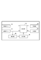
さらに、通信装置とMCIとのSC光ファイバによる接続を作業者が変更するのではなく、通信装置において行う構成とすることができる。図5は、誤接続からの復帰機構を有する通信装置の構成図である。図5において送信部14は、情報を搬送する光信号を生成して送信し、受信部13は、対向する通信装置の送信部14が生成した光信号を受信して復調・復号する。通信装置の受信ポート10、送信ポート11、受信部13及び送信部14は、それぞれ、光切替(SW)部12のポート#1、#2、#3及び#4に接続される。
光SW部12は、制御部16の制御により第1状態又は第2状態に設定される。第1状態において、光SW部12は、ポート#1とポート#3を接続し、かつ、ポート#2とポート#4を接続する。一方、第2状態において、光SW部12は、ポート#1とポート#4を接続し、かつ、ポート#2とポート#3を接続する。測定部15は、光SW部12と送信ポート11との間の光ファイバを伝搬する光のレベルを測定し、測定したレベルを制御部16に通知する。なお、通信装置は、図示しない管理装置とネットワークを介して通信でき、作業者は、管理装置を介して、遠隔から通信装置を制御できるものとする。
対向する2つの通信装置#1及び通信装置#3を光伝送路により接続する際、作業者は、対向する2つの通信装置#1及び通信装置#3を誤接続検出モードに設定する。誤接続検出モードにおいて、通信装置の制御部16は、光SW部12を所定の状態、例えば、第1状態にする。そして、作業者は、対向する2つの通信装置の内の一方の通信装置の送信部14に光信号を送信させ、他方の通信装置の測定部15に光レベルを測定させる。なお、この際、他方の通信装置の送信部14には光信号の送信を停止させる。対向する2つの通信装置の送信ポート10と受信ポート11が正しく接続されている場合、他方の光通信装置の測定部15が検出する光のレベルは所定値より小さい。制御部16は、誤接続検出モードにおいて測定部15より光のレベルが所定値より小さいとの測定結果を受信すると、光SW部12の状態を変更せず、誤接続が無い旨を作業者に通知する。一方、対向する2つの通信装置の送信ポート10同士が接続され、かつ、受信ポート11同士が接続されている場合、他方の光通信装置の測定部15が検出する光のレベルは所定値以上になる。制御部16は、誤接続検出モードにおいて測定部15より光のレベルが所定値以上との測定結果を受信すると、光SW部12の状態を変更して、誤接続を解消させ、かつ、誤接続が有った旨を作業者に通知する。
なお、図5において測定部15は、送信ポート11と光SW部12との間で光のレベルを検知していたが、送信部14と光SW部12との間で光のレベルを検知する構成とすることもできる。また、受信ポート10と光SW部12との間や、受信部13と光SW部12との間で光レベルを検知する構成とすることもできる。この場合、誤接続検出モードにおいて、測定部15が検出する光のレベルが所定値以上であると、誤接続が生じていないと判定する。この場合、受信部13が測定部15の機能を具備して兼ねる構成とすることもできる。
以上、MC光ファイバの断面内の所定方向の線に対して対称の位置に配置された2つのコアを、対向する2つの通信装置が送受信に使用する2つのコアとする。なお、所定方向の線は、MCIのコネクタのロック機構の位置に基づき決定する。この構成により、任意の位置でMCIのタイプが取り違えられたとしても、対向する2つの通信装置の送信ポート間及び受信ポート間が接続される様になるのみであり、対向しない無関係な2つの通信装置が接続されることを防ぐことができる。また、対向する2つの通信装置の送信ポート間及び受信ポート間が接続される様になるのみであるため、SC光ファイバの接続側で簡易に誤接続を解消させることができる。また、通信装置に光SW部を設けることで、作業者が通信装置の設置場所に出向くことなく、遠隔から誤接続を解消させることができる。
なお、図3A及び図3Bにおいては、MC光ファイバの断面内の所定方向の線上、つまり、ロック機構とMC光ファイバの中心を通る線上にはコアが存在しなかった。しかしながら、所定方向の線上に偶数個のコアが存在する場合も生じる。例えば、図3A及び図3Bのコア配置を45度だけ回転させると、所定方向の線上に2つのコアが存在することになる。さらに、異なる2つの半径の円周上に等間隔でコアを配置した場合、所定方向の線上に4つのコアが存在する場合も生じ得る。この所定方向の線上のコアについては、第1MCIと第2MCIを取り違えても誤接続は生じない。したがって、本実施形態では、所定方向の線上にないコアについては、所定方向の線に対して線対称の関係にある2つのコアを、対向する2つの通信装置が送受信に使用するコアのペアに使用する。一方、所定方向の線上にある偶数個のコアについては、任意に選択したコアのペアを対向する2つの通信装置の送受信のために使用することができる。
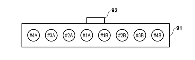
なお、4つのコアを有するMC光ファイバにより本実施形態の説明を行ったが、複数のコアが線対称に配置されていれば良く、コア数は4つ以上であっても良い。さらに、複数のコアを有する光ファイバとしてMC光ファイバにより本実施形態の説明を行ったが、複数のSC光ファバイを1つのテープ状にした、所謂、テープ芯線に対しても本発明を適用することができる。図6A及び図6Bは、8つのSC光ファイバを含むテープ芯線に使用される第1MCI及び第2MCIのコネクタの断面を示している。なお、参照符号91は、コネクタ本体を示し、参照符号92は、ロック機構を示している。図6A及び図6Bにおいては、一列に配置された複数のコアの中心を通る線に対して対称となる位置に配置された2つのコアを1つのペアとし、この1つのペアに含まれる2つのコアを対向する2つの通信装置が送受信に使用するものとしている。具体的には、コア#1A及びコア#1Bが1つのペアであり、コア#2A及びコア#2Bが1つのペアであり、コア#3A及びコア#3Bが1つのペアであり、コア#4A及びコア#4Bが1つのペアである。
<第二実施形態>
続いて、第二実施形態について第一実施形態との相違点を中心に説明する。第一実施形態においては、誤接続を解消させるために光SW部12、監視部15及び制御部16を通信装置に設けていた。本実施形態においては、パッシブなデバイスのみで誤接続を解消させる。なお、本実施形態においては、光伝送路に設けられた中継器により、対向する2つの通信装置が送受信に使用する2つのコアのそれぞれは、互いに異なる方向に伝搬する光信号のみを通過させるものとする。具体的には、図4A及び図4Bに示す様に接続している場合、光伝送路のコア#1Aは、通信装置#1から通信装置#3に向かう方向の光信号のみを通過させ、通信装置#3から通信装置#1に向かう方向の光信号を阻止し、光伝送路のコア#1Bは、通信装置#3から通信装置#1に向かう方向の光信号のみを通過させ、通信装置#1から通信装置#3に向かう方向の光信号を阻止する。
続いて、第二実施形態について第一実施形態との相違点を中心に説明する。第一実施形態においては、誤接続を解消させるために光SW部12、監視部15及び制御部16を通信装置に設けていた。本実施形態においては、パッシブなデバイスのみで誤接続を解消させる。なお、本実施形態においては、光伝送路に設けられた中継器により、対向する2つの通信装置が送受信に使用する2つのコアのそれぞれは、互いに異なる方向に伝搬する光信号のみを通過させるものとする。具体的には、図4A及び図4Bに示す様に接続している場合、光伝送路のコア#1Aは、通信装置#1から通信装置#3に向かう方向の光信号のみを通過させ、通信装置#3から通信装置#1に向かう方向の光信号を阻止し、光伝送路のコア#1Bは、通信装置#3から通信装置#1に向かう方向の光信号のみを通過させ、通信装置#1から通信装置#3に向かう方向の光信号を阻止する。
図7は、誤接続からの復帰機構を有する通信装置の構成図である。本実施形態においては、図5の光SW部12に代えて光カプラ17を使用している。また、送信部14と光カプラ17の間には光アイソレータ18を設けている。光アイソレータ18は、送信部14から光カプラ17に向かう光信号を通過させるが、光カプラ17から送信部14に向かう光信号を阻止する。
光カプラ17のポート#1に入力された光信号は、等振幅に2分岐され、それぞれ、ポート#3及びポート#4から出力される。光カプラ17のポート#2に入力された光信号は、等振幅に2分岐され、それぞれ、ポート#3及びポート#4から出力される。光カプラ17のポート#3に入力された光信号は、等振幅に2分岐され、それぞれ、ポート#1及びポート#2から出力される。光カプラ17のポート#4に入力された光信号は、等振幅に2分岐され、それぞれ、ポート#1及びポート#2から出力される。
送信部14が送信する光信号は、光カプラのポート#1及びポート#2から出力され、よって、受信ポート10及び送信ポート11の両方から出力される。しかしながら、受信ポート10から光伝送路に向けて出力された光信号は、上述した様に、光伝送路において阻止され、送信ポート11から出力された光信号のみが対向する通信装置に向けて伝送される。一方、対向する通信装置が送信した光信号は、光伝送路と通信装置とを接続するMCIのタイプに応じて、受信ポート10又は送信ポート11に入力される。対向する通信装置からの光信号が、受信ポート10と送信ポート11のどちらから入力されたかに拘わらず、光カプラ17は、対向する通信装置からの光信号をポート#3及びポート#4から出力する。ポート3から出力された光信号は受信部13で受信される。一方、ポート#4から出力された光信号は、光アイソレータ18で阻止される。この様に、MCIのタイプ間違いが生じても、対向する2つの通信装置は通信を行うことができる。
本発明は上記実施の形態に制限されるものではなく、本発明の精神及び範囲から離脱することなく、様々な変更及び変形が可能である。従って、本発明の範囲を公にするために、以下の請求項を添付する。
本願は、2019年9月2日提出の日本国特許出願特願2019-159693を基礎として優先権を主張するものであり、その記載内容の全てを、ここに援用する。
Claims (13)
- 光信号を送信する送信手段と、
光信号を受信する受信手段と、
送信ポートと、
受信ポートと、
前記送信手段、前記受信手段、前記送信ポート及び前記受信ポートに接続する切替手段であって、前記送信手段と前記送信ポートを接続し、かつ、前記受信手段と前記受信ポートを接続する第1状態と、前記送信手段と前記受信ポートを接続し、かつ、前記受信手段と前記送信ポートを接続する第2状態に設定可能な前記切替手段と、
前記受信ポート又は前記送信ポートから入力される光のレベルを監視する監視手段と、
前記監視手段が監視する前記光のレベルに基づき前記切替手段を前記第1状態及び前記第2状態のいずれかに設定する制御手段と、
を備えている、通信装置。 - 前記制御手段は、対向する通信装置が光信号を送信しているときに前記監視手段が監視する前記光のレベルに基づき前記切替手段を前記第1状態及び前記第2状態のいずれかに設定する、請求項1に記載の通信装置。
- 前記監視手段は、前記送信ポートから入力される光のレベルを監視し、
前記制御手段は、前記対向する通信装置が光信号を送信しているときに前記送信ポートから入力される前記光のレベルが所定値より小さいと前記切替手段を前記第1状態に設定し、前記光のレベルが前記所定値より大きいと前記切替手段を前記第2状態に設定する、請求項2に記載の通信装置。 - 前記監視手段は、前記受信ポートから入力される光のレベルを監視し、
前記制御手段は、前記対向する通信装置が光信号を送信しているときに前記受信ポートから入力される前記光のレベルが所定値より大きいと前記切替手段を前記第1状態に設定し、前記光のレベルが前記所定値より小さいと前記切替手段を前記第2状態に設定する、請求項2に記載の通信装置。 - 光信号を送信する送信手段と、
光信号を受信する受信手段と、
送信ポートと、
受信ポートと、
前記送信手段に接続する阻止手段と、
前記阻止手段、前記受信手段、前記送信ポート及び前記受信ポートに接続される光カプラと、
を備え、
前記阻止手段は、前記送信手段が送信する前記光信号を通過させるが、前記送信手段に向かう光信号を阻止し、
前記光カプラは、前記送信手段からの前記光信号を前記送信ポート及び前記受信ポートそれぞれに出力し、前記受信ポートからの光信号を前記受信手段及び前記阻止手段それぞれに出力し、前記送信ポートからの光信号を前記受信手段及び前記阻止手段それぞれに出力する、通信装置。 - 前記通信装置は、光ファイバが有する複数のコアの内、当該光ファイバの長手方向と直交する断面において、当該断面の中心を通る所定方向の直線上にはないコアを使用して対向する通信装置と前記光信号の送受信を行う場合、当該直線に対して互いに線対称の位置にある2つのコアを使用して前記対向する通信装置と前記光信号の送受信を行う、請求項1から5のいずれか1項に記載の通信装置。
- 前記所定方向は、前記光ファイバが有する前記複数のコアそれぞれをシングルコア光ファイバに接続する接続部材に使用されているコネクタのロック機構の位置に基づき決定される、請求項6に記載の通信装置。
- 前記光ファイバは、前記複数のコアを有するマルチコア光ファイバである、請求項6又は7に記載の通信装置。
- 前記光ファイバは、前記複数のコアを有するテープ芯線である、請求項6又は7に記載の通信装置。
- 複数のコアを有する光ファイバを使用する通信システムであって、
当該光ファイバの長手方向と直交する断面において、当該断面の中心を通る所定方向の直線上にはないコアについては、当該直線に対して互いに線対称の位置にある2つのコアを使用して対向する2つの通信装置が送受信を行う、通信システム。 - 前記所定方向は、前記光ファイバが有する前記複数のコアそれぞれをシングルコア光ファイバに接続する接続部材に使用されているコネクタのロック機構の位置に基づき決定される、請求項10に記載の通信システム。
- 前記光ファイバは、前記複数のコアを有するマルチコア光ファイバである、請求項10又は11に記載の通信システム。
- 前記光ファイバは、前記複数のコアを有するテープ芯線である、請求項10又は11に記載の通信システム。
Priority Applications (4)
| Application Number | Priority Date | Filing Date | Title |
|---|---|---|---|
| JP2021543708A JP7254193B2 (ja) | 2019-09-02 | 2020-08-25 | 通信装置及び通信システム |
| EP20861721.7A EP4027536A4 (en) | 2019-09-02 | 2020-08-25 | COMMUNICATION DEVICE AND COMMUNICATION SYSTEM |
| CN202080059553.8A CN114270731B (zh) | 2019-09-02 | 2020-08-25 | 通信装置以及通信系统 |
| US17/588,591 US11966083B2 (en) | 2019-09-02 | 2022-01-31 | Communication device and communication system |
Applications Claiming Priority (2)
| Application Number | Priority Date | Filing Date | Title |
|---|---|---|---|
| JP2019159693 | 2019-09-02 | ||
| JP2019-159693 | 2019-09-02 |
Related Child Applications (1)
| Application Number | Title | Priority Date | Filing Date |
|---|---|---|---|
| US17/588,591 Continuation US11966083B2 (en) | 2019-09-02 | 2022-01-31 | Communication device and communication system |
Publications (1)
| Publication Number | Publication Date |
|---|---|
| WO2021044902A1 true WO2021044902A1 (ja) | 2021-03-11 |
Family
ID=74853177
Family Applications (1)
| Application Number | Title | Priority Date | Filing Date |
|---|---|---|---|
| PCT/JP2020/031972 Ceased WO2021044902A1 (ja) | 2019-09-02 | 2020-08-25 | 通信装置及び通信システム |
Country Status (5)
| Country | Link |
|---|---|
| US (1) | US11966083B2 (ja) |
| EP (1) | EP4027536A4 (ja) |
| JP (1) | JP7254193B2 (ja) |
| CN (1) | CN114270731B (ja) |
| WO (1) | WO2021044902A1 (ja) |
Citations (5)
| Publication number | Priority date | Publication date | Assignee | Title |
|---|---|---|---|---|
| JP2003134089A (ja) * | 2001-10-26 | 2003-05-09 | Fujitsu Ltd | 伝送装置 |
| JP2005051750A (ja) * | 2003-07-16 | 2005-02-24 | Nec Infrontia Corp | 送受信伝送路の誤接続自動修正方法及びこれを用いた伝送装置並びに伝送システム |
| JP2012022176A (ja) | 2010-07-15 | 2012-02-02 | Hitachi Cable Ltd | マルチコアインターフェイス |
| WO2015025629A1 (ja) * | 2013-08-23 | 2015-02-26 | 株式会社フジクラ | 光ファイバの調心装置、接続装置、調心方法、および接続方法 |
| JP2019159693A (ja) | 2018-03-12 | 2019-09-19 | Kddi株式会社 | 情報処理装置、情報処理端末、及びプログラム |
Family Cites Families (7)
| Publication number | Priority date | Publication date | Assignee | Title |
|---|---|---|---|---|
| DE3605248A1 (de) * | 1986-02-19 | 1987-09-03 | Standard Elektrik Lorenz Ag | Optischer sende/empfangsmodul |
| JP4363477B2 (ja) * | 2007-10-09 | 2009-11-11 | 沖電気工業株式会社 | ネットワークシステム |
| CN102340355B (zh) * | 2011-09-26 | 2019-03-12 | 中兴通讯股份有限公司 | 一种自适应光纤收发方向的方法及装置 |
| EP2582152B1 (en) * | 2011-10-12 | 2018-08-29 | ADVA Optical Networking SE | Remote node and network architecture and data transmission method for a fiber-optic network, especially for low bit-rate data transmission |
| US9696513B2 (en) * | 2013-11-22 | 2017-07-04 | Corning Optical Communications LLC | Multicore optical fibers and methods of manufacturing the same |
| JP6787803B2 (ja) * | 2017-01-30 | 2020-11-18 | 日本電信電話株式会社 | 光コネクタおよび光伝送システム |
| EP4296733A4 (en) * | 2021-02-19 | 2025-02-12 | Fujikura Ltd. | OPTICAL INPUT/OUTPUT DEVICE |
-
2020
- 2020-08-25 CN CN202080059553.8A patent/CN114270731B/zh active Active
- 2020-08-25 EP EP20861721.7A patent/EP4027536A4/en active Pending
- 2020-08-25 WO PCT/JP2020/031972 patent/WO2021044902A1/ja not_active Ceased
- 2020-08-25 JP JP2021543708A patent/JP7254193B2/ja active Active
-
2022
- 2022-01-31 US US17/588,591 patent/US11966083B2/en active Active
Patent Citations (5)
| Publication number | Priority date | Publication date | Assignee | Title |
|---|---|---|---|---|
| JP2003134089A (ja) * | 2001-10-26 | 2003-05-09 | Fujitsu Ltd | 伝送装置 |
| JP2005051750A (ja) * | 2003-07-16 | 2005-02-24 | Nec Infrontia Corp | 送受信伝送路の誤接続自動修正方法及びこれを用いた伝送装置並びに伝送システム |
| JP2012022176A (ja) | 2010-07-15 | 2012-02-02 | Hitachi Cable Ltd | マルチコアインターフェイス |
| WO2015025629A1 (ja) * | 2013-08-23 | 2015-02-26 | 株式会社フジクラ | 光ファイバの調心装置、接続装置、調心方法、および接続方法 |
| JP2019159693A (ja) | 2018-03-12 | 2019-09-19 | Kddi株式会社 | 情報処理装置、情報処理端末、及びプログラム |
Non-Patent Citations (1)
| Title |
|---|
| See also references of EP4027536A4 |
Also Published As
| Publication number | Publication date |
|---|---|
| EP4027536A4 (en) | 2022-11-02 |
| CN114270731B (zh) | 2024-05-24 |
| US20220187541A1 (en) | 2022-06-16 |
| US11966083B2 (en) | 2024-04-23 |
| JP7254193B2 (ja) | 2023-04-07 |
| CN114270731A (zh) | 2022-04-01 |
| EP4027536A1 (en) | 2022-07-13 |
| JPWO2021044902A1 (ja) | 2021-03-11 |
Similar Documents
| Publication | Publication Date | Title |
|---|---|---|
| US5069521A (en) | Optical transmission apparatus | |
| CA1276236C (en) | Fault direction in an optical communications system | |
| CN104518826B (zh) | 一种监测光纤故障的方法、设备及系统 | |
| US5793481A (en) | System, method and device for monitoring a fiber optic cable | |
| JPH0259664B2 (ja) | ||
| JP7254193B2 (ja) | 通信装置及び通信システム | |
| KR20190047278A (ko) | 광케이블의 해킹보안 방법 및 장치 | |
| US9172461B2 (en) | Optical fibers with varied mode-dependent loss | |
| CN213342242U (zh) | 基于时分复用的解码装置、qkd系统及量子保密通信系统 | |
| US5730053A (en) | Bus system for a printing machine | |
| JP7058535B2 (ja) | 光伝送装置における光ファイバの接続確認方法 | |
| KR100333954B1 (ko) | 단일코어를 이용한 광통신망 이중화와 고장감시방법 및 그장치 | |
| US9432752B2 (en) | Optical transmission system | |
| JP6654595B2 (ja) | マルチコア光ファイバを使用する光ファイバ通信システム及びコア識別方法 | |
| JP7734640B2 (ja) | 光伝送路接続性確認システム | |
| US20260081681A1 (en) | Detecting transmitter-receiver misconfigurations in optical signal paths | |
| JPH0246031A (ja) | 障害点探索方式 | |
| CN114499692A (zh) | 时分复用单元及方法、解码装置、qkd系统及量子通信系统 | |
| JPS63501758A (ja) | 多重アクセス通信網の動作方法および通信機密保護方法ならびに多重アクセス通信装置 | |
| JP6194560B2 (ja) | ノード装置および通信方法 | |
| JPH0383428A (ja) | ループ型光データ通信システム | |
| US20160033726A1 (en) | Low loss fiber optic harness | |
| JP2014017580A (ja) | ネットワークシステム | |
| JPH04345219A (ja) | 光中継局および光端局 | |
| KR20200063112A (ko) | 광학적 시간 영역 반사 측정기를 이용한 광선로 원거리 노드 식별 시스템 및 식별 방법 그리고 식별용 소자 |
Legal Events
| Date | Code | Title | Description |
|---|---|---|---|
| 121 | Ep: the epo has been informed by wipo that ep was designated in this application |
Ref document number: 20861721 Country of ref document: EP Kind code of ref document: A1 |
|
| WWE | Wipo information: entry into national phase |
Ref document number: 2021543708 Country of ref document: JP |
|
| NENP | Non-entry into the national phase |
Ref country code: DE |
|
| ENP | Entry into the national phase |
Ref document number: 2020861721 Country of ref document: EP Effective date: 20220404 |