WO2021045084A1 - 熱交換器 - Google Patents
熱交換器 Download PDFInfo
- Publication number
- WO2021045084A1 WO2021045084A1 PCT/JP2020/033227 JP2020033227W WO2021045084A1 WO 2021045084 A1 WO2021045084 A1 WO 2021045084A1 JP 2020033227 W JP2020033227 W JP 2020033227W WO 2021045084 A1 WO2021045084 A1 WO 2021045084A1
- Authority
- WO
- WIPO (PCT)
- Prior art keywords
- heat exchange
- heat
- heat transfer
- entrance
- heat exchanger
- Prior art date
- Legal status (The legal status is an assumption and is not a legal conclusion. Google has not performed a legal analysis and makes no representation as to the accuracy of the status listed.)
- Ceased
Links
Images


Classifications
-
- F—MECHANICAL ENGINEERING; LIGHTING; HEATING; WEAPONS; BLASTING
- F28—HEAT EXCHANGE IN GENERAL
- F28D—HEAT-EXCHANGE APPARATUS, NOT PROVIDED FOR IN ANOTHER SUBCLASS, IN WHICH THE HEAT-EXCHANGE MEDIA DO NOT COME INTO DIRECT CONTACT
- F28D1/00—Heat-exchange apparatus having stationary conduit assemblies for one heat-exchange medium only, the media being in contact with different sides of the conduit wall, in which the other heat-exchange medium is a large body of fluid, e.g. domestic or motor car radiators
- F28D1/02—Heat-exchange apparatus having stationary conduit assemblies for one heat-exchange medium only, the media being in contact with different sides of the conduit wall, in which the other heat-exchange medium is a large body of fluid, e.g. domestic or motor car radiators with heat-exchange conduits immersed in the body of fluid
- F28D1/04—Heat-exchange apparatus having stationary conduit assemblies for one heat-exchange medium only, the media being in contact with different sides of the conduit wall, in which the other heat-exchange medium is a large body of fluid, e.g. domestic or motor car radiators with heat-exchange conduits immersed in the body of fluid with tubular conduits
- F28D1/053—Heat-exchange apparatus having stationary conduit assemblies for one heat-exchange medium only, the media being in contact with different sides of the conduit wall, in which the other heat-exchange medium is a large body of fluid, e.g. domestic or motor car radiators with heat-exchange conduits immersed in the body of fluid with tubular conduits the conduits being straight
- F28D1/0535—Heat-exchange apparatus having stationary conduit assemblies for one heat-exchange medium only, the media being in contact with different sides of the conduit wall, in which the other heat-exchange medium is a large body of fluid, e.g. domestic or motor car radiators with heat-exchange conduits immersed in the body of fluid with tubular conduits the conduits being straight the conduits having a non-circular cross-section
- F28D1/05358—Assemblies of conduits connected side by side or with individual headers, e.g. section type radiators
-
- F—MECHANICAL ENGINEERING; LIGHTING; HEATING; WEAPONS; BLASTING
- F28—HEAT EXCHANGE IN GENERAL
- F28D—HEAT-EXCHANGE APPARATUS, NOT PROVIDED FOR IN ANOTHER SUBCLASS, IN WHICH THE HEAT-EXCHANGE MEDIA DO NOT COME INTO DIRECT CONTACT
- F28D21/00—Heat-exchange apparatus not covered by any of the groups F28D1/00 - F28D20/00
-
- F—MECHANICAL ENGINEERING; LIGHTING; HEATING; WEAPONS; BLASTING
- F28—HEAT EXCHANGE IN GENERAL
- F28F—DETAILS OF HEAT-EXCHANGE AND HEAT-TRANSFER APPARATUS, OF GENERAL APPLICATION
- F28F9/00—Casings; Header boxes; Auxiliary supports for elements; Auxiliary members within casings
- F28F9/02—Header boxes; End plates
- F28F9/0219—Arrangements for sealing end plates into casing or header box; Header box sub-elements
- F28F9/0221—Header boxes or end plates formed by stacked elements
-
- F—MECHANICAL ENGINEERING; LIGHTING; HEATING; WEAPONS; BLASTING
- F28—HEAT EXCHANGE IN GENERAL
- F28D—HEAT-EXCHANGE APPARATUS, NOT PROVIDED FOR IN ANOTHER SUBCLASS, IN WHICH THE HEAT-EXCHANGE MEDIA DO NOT COME INTO DIRECT CONTACT
- F28D21/00—Heat-exchange apparatus not covered by any of the groups F28D1/00 - F28D20/00
- F28D2021/0019—Other heat exchangers for particular applications; Heat exchange systems not otherwise provided for
- F28D2021/0028—Other heat exchangers for particular applications; Heat exchange systems not otherwise provided for for cooling heat generating elements, e.g. for cooling electronic components or electric devices
-
- F—MECHANICAL ENGINEERING; LIGHTING; HEATING; WEAPONS; BLASTING
- F28—HEAT EXCHANGE IN GENERAL
- F28F—DETAILS OF HEAT-EXCHANGE AND HEAT-TRANSFER APPARATUS, OF GENERAL APPLICATION
- F28F2245/00—Coatings; Surface treatments
-
- H—ELECTRICITY
- H01—ELECTRIC ELEMENTS
- H01M—PROCESSES OR MEANS, e.g. BATTERIES, FOR THE DIRECT CONVERSION OF CHEMICAL ENERGY INTO ELECTRICAL ENERGY
- H01M10/00—Secondary cells; Manufacture thereof
- H01M10/60—Heating or cooling; Temperature control
- H01M10/61—Types of temperature control
- H01M10/613—Cooling or keeping cold
-
- H—ELECTRICITY
- H01—ELECTRIC ELEMENTS
- H01M—PROCESSES OR MEANS, e.g. BATTERIES, FOR THE DIRECT CONVERSION OF CHEMICAL ENERGY INTO ELECTRICAL ENERGY
- H01M10/00—Secondary cells; Manufacture thereof
- H01M10/60—Heating or cooling; Temperature control
- H01M10/62—Heating or cooling; Temperature control specially adapted for specific applications
- H01M10/625—Vehicles
-
- H—ELECTRICITY
- H01—ELECTRIC ELEMENTS
- H01M—PROCESSES OR MEANS, e.g. BATTERIES, FOR THE DIRECT CONVERSION OF CHEMICAL ENERGY INTO ELECTRICAL ENERGY
- H01M10/00—Secondary cells; Manufacture thereof
- H01M10/60—Heating or cooling; Temperature control
- H01M10/65—Means for temperature control structurally associated with the cells
- H01M10/655—Solid structures for heat exchange or heat conduction
- H01M10/6556—Solid parts with flow channel passages or pipes for heat exchange
-
- Y—GENERAL TAGGING OF NEW TECHNOLOGICAL DEVELOPMENTS; GENERAL TAGGING OF CROSS-SECTIONAL TECHNOLOGIES SPANNING OVER SEVERAL SECTIONS OF THE IPC; TECHNICAL SUBJECTS COVERED BY FORMER USPC CROSS-REFERENCE ART COLLECTIONS [XRACs] AND DIGESTS
- Y02—TECHNOLOGIES OR APPLICATIONS FOR MITIGATION OR ADAPTATION AGAINST CLIMATE CHANGE
- Y02E—REDUCTION OF GREENHOUSE GAS [GHG] EMISSIONS, RELATED TO ENERGY GENERATION, TRANSMISSION OR DISTRIBUTION
- Y02E60/00—Enabling technologies; Technologies with a potential or indirect contribution to GHG emissions mitigation
- Y02E60/10—Energy storage using batteries
Definitions
- the present invention relates to a heat exchanger in which a laminated material in which a resin coating layer is laminated on a metal heat transfer layer is provided on an outer surface portion.
- Hybrid electric vehicles HEVs
- electric vehicles EVs
- a battery device that supplies power to drive an electric motor.
- a battery device a battery device in which a large number of small cells made of various secondary batteries such as a lithium secondary battery are connected in series or in parallel to form an assembled battery is generally used.
- a plurality of assembled batteries are combined in series or in parallel, and the capacity of the battery device is further increased.
- lithium secondary batteries which are often used as battery devices, have a large change in performance and life depending on the operating temperature, so it is preferable to control the temperature to an appropriate temperature for efficient use over a long period of time.
- the temperature of each set battery rises, which may reduce the performance and life.
- Patent Document 1 a technique has been developed in which a plurality of assembled batteries are cooled by using a thin heat exchanger as shown in Patent Document 1 below.
- this heat exchanger two metal dish-shaped plates are opposed to each other to form a heat exchanger (flat tube), and a flat tube is arranged between each of a plurality of assembled batteries to form an assembled battery.
- the heat generated from each of the cells is released to the outside through the refrigerant (cooling water) flowing in the flat tube.
- heat exchangers for cooling a plurality of assembled batteries as an automobile battery device are required to be as thin, small and lightweight, and low in cost as much as other automobile parts.
- the adoption of heat exchangers using highly flexible laminate materials is being considered.
- a heat exchanger using a laminated material is provided with an exterior body made of a laminated material in which a resin coating layer is laminated on both sides of a metal heat transfer layer. Then, the coolant introduced from the entrance (doorway) of the exterior body circulates inside the exterior body and flows out from the outlet (doorway) of the exterior body. In this way, the assembled battery is cooled by exchanging heat between the coolant circulating in the outer body and the battery such as the assembled battery arranged in contact with the outer surface of the outer body.
- a preferred embodiment of the present invention has been made in view of the above-mentioned and / or other problems in the related art.
- a preferred embodiment of the present invention is one that can significantly improve existing methods and / or devices.
- the present invention has been made in view of the above problems, and in a heat exchanger using a laminated material, it is possible to improve the flow characteristics of the heat exchange medium at the entrance / exit forming portion while reducing the thickness, and sufficient heat is obtained. It is an object of the present invention to provide a heat exchanger capable of obtaining exchange performance.
- the present invention includes the following means.
- a heat transfer section in which the hollow portion inside is configured as a heat exchange flow path through which the heat exchange medium flows, and an inlet / outlet for connecting the inside to the heat exchange flow path and allowing the heat exchange medium to flow in and out.
- Heat exchange is provided so as to exchange heat between the heat exchange medium flowing through the heat exchange flow path and the heat exchange target member arranged on the outer surface of the heat transfer portion. It ’s a vessel, At least a part of the outer surface portion of the heat transfer portion is composed of a coating sheet which is a laminate material in which a resin coating layer is provided on at least one side of the metal heat transfer layer.
- a heat exchanger characterized in that the outer dimension thickness of the entrance / exit forming portion is formed to be thicker than the outer dimension thickness of the heat transfer portion.
- the entrance / exit forming portion and the heat transfer portion are arranged along the flow path direction of the heat exchange flow path. Further, in the present invention, the entrance / exit forming portion is arranged at the edge portion of the heat transfer portion.
- a plurality of the heat exchange channels extend from one end edge portion of the heat transfer portion toward the other end edge portion and are arranged in parallel.
- the entrance / exit forming portion includes an upstream header member arranged along the upstream end portion of the plurality of heat exchange flow paths and a downstream header member arranged along the downstream end portion.
- the heat exchange medium that has flowed into the upstream header member through the inlet / outlet is diverted and flows into each heat exchange flow path, and the heat exchange medium that has flowed out from each heat exchange flow path joins at the downstream header member.
- the heat exchanger according to any one of items 1 to 4 above, which is configured to flow out from the inlet / outlet on the downstream side.
- One side in the thickness direction is the front side, and the other side is the back side.
- the front surface side of the entrance / exit forming portion is arranged so as to project toward the front surface side with respect to the front surface side of the heat transfer portion, and the back surface side of the entrance / exit forming portion projects toward the back surface side with respect to the back surface side of the heat transfer portion.
- the heat exchanger according to any one of the preceding items 1 to 5, which is arranged so as to be used.
- a plurality of the entrance / exit forming portions are provided.
- a spacer member for maintaining the height of the heat exchange flow path is provided in the hollow portion of the heat transfer portion.
- a reinforcing member having a function as a spacer for maintaining the thickness of the entrance / exit forming portion is provided.
- the heat exchanger according to any one of items 1 to 9 above, wherein the spacer member and the reinforcing member are integrally formed.
- the entrance / exit forming portion is formed thicker than the heat transfer portion, a sufficient flow path in the entrance / exit forming portion can be sufficiently secured and the flow characteristics and heat exchange performance are improved.
- the heat transfer portion in which the heat exchange target member such as a battery is installed can be made thinner, and the size and compactness can be made as a whole. Since the heat exchange target member is not arranged in the entrance / exit forming portion, there is a margin in space, and even if the thickness is increased, it does not interfere with other members and does not cause an adverse effect.
- the thickness of the entrance / exit forming portion can be sufficiently secured against compressive stress and the like, and the heat exchange flowing inside the heat exchanger can be sufficiently secured.
- the flow characteristics of the medium can be improved, and the heat exchange performance can be sufficiently ensured.
- the spacer member is arranged in the heat transfer portion, a sufficient flow path cross section of the heat exchange flow path of the heat transfer portion can be sufficiently secured, and from this point as well, heat can be sufficiently secured.
- the flow characteristics of the exchange medium can be improved, and the heat exchange performance can be improved.
- the heat exchange medium can be evenly distributed to a plurality of heat exchange channels arranged side by side, and the entire heat exchange target member is evenly and evenly distributed.
- the heat can be exchanged, and the heat exchange performance can be further improved.
- the flow characteristics of the heat exchange medium at the entrance / exit forming portion can be improved, and the heat exchange performance can be sufficiently ensured, while further reducing the thickness.
- the number of heat transfer portions can be increased with respect to the inlet / outlet forming portions, and more heat exchange target members can be heat-exchanged while limiting the number of inlet / outlet forming portions. Heat exchange can be performed even more efficiently.
- the heat exchange performance can be improved more reliably while further reducing the thickness.
- the heat exchanger of the invention since the required members are integrated, the number of parts can be reduced, the structure can be simplified, and the assembly workability can be improved.
- the coating sheet can be effectively coated, and defects such as liquid leakage can be reliably prevented.
- FIG. 1 is a cross-sectional view showing a battery cooling unit using a heat exchange panel as a heat exchanger according to the first embodiment of the present invention.
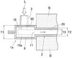
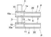
- FIG. 2 is an enlarged cross-sectional view showing the periphery of the entrance / exit forming portion in the battery cooling unit of the first embodiment.
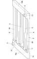
- FIG. 3 is a perspective view showing a state in which the covering sheet is removed in the heat exchange panel of the first embodiment.
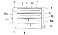
- FIG. 4 is a plan view for explaining the flow path of the heat exchange panel of the first embodiment.
- FIG. 5 is a cross-sectional view showing a battery cooling unit using the heat exchange panel P as the heat exchanger according to the second embodiment of the present invention.
- FIG. 6 is a perspective view showing a state in which the covering sheet is removed in the heat exchange panel of the second embodiment.
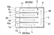
- FIG. 7 is a plan view for explaining the flow path of the heat exchange panel of the second embodiment.
- FIG. 8 is a plan view for explaining the flow path of the heat exchange panel as the heat exchanger according to the third embodiment of the present invention.
- FIG. 9 is a cross-sectional view showing a heat exchange panel as a heat exchanger according to a fourth embodiment of the present invention.
- FIG. 10 is a perspective view showing the heat exchange panel of the fourth embodiment.
- FIG. 11 is a cross-sectional view for explaining a first use example of the heat exchange panel as the heat exchanger of the present invention.
- FIG. 12 is a cross-sectional view for explaining a second use example of the heat exchange panel as the heat exchanger of the present invention.
- FIG. 13 is an enlarged cross-sectional view showing the periphery of the entrance / exit forming portion of the heat exchanger, which is the first modification of the present invention.
- FIG. 14 is a cross-sectional view showing a battery cooling unit using a heat exchange panel as a heat exchanger, which is a second modification of the present invention.
- FIG. 15 is a perspective view showing a heat exchange panel of the second modification.
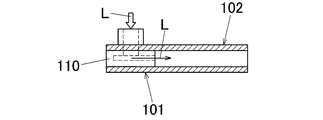
- FIG. 16 is an enlarged cross-sectional view showing the periphery of the entrance / exit forming portion of the thin heat exchanger as the first reference example.
- FIG. 17 is an enlarged cross-sectional view showing the periphery of the entrance / exit forming portion of the thick heat exchanger as the second reference example.
- FIG. 1 is a cross-sectional view showing a battery cooling unit using a heat exchange panel P as a heat exchanger according to the first embodiment of the present invention
- FIG. 2 is an enlarged cross-sectional view showing the periphery of an entrance / exit forming portion in the battery cooling unit
- FIG. 3 is a perspective view showing a state in which the coating sheet is removed from the heat exchange panel P
- FIG. 4 is a plan view for explaining the flow of the coolant L in the heat exchange panel P.
- the installation state (orientation) in actual use is not limited to the state shown in FIG. Is also good.
- the heat exchange panel P of the first embodiment is a single battery (battery cell), an assembled battery (battery pack), or the like for supplying power for driving an electric motor of an electric vehicle or the like. It is used to cool the battery.
- the heat exchange panel (cooler) P is arranged between a pair of entrance / exit forming portions 1a and 1b on the upstream side and the downstream side provided at both end edges in the vertical direction and a pair of entrance / exit forming portions 1a and 1b. It is provided with a heat transfer unit 2.
- Header members 10a and 10b are arranged in the pair of entrance / exit forming portions 1a and 1b, respectively.
- the pair of header members 10a and 10b on the upstream side and the downstream side are arranged at both end edges in the vertical direction along the horizontal direction and are arranged parallel to each other.
- the header members 10a and 10b are formed in a substantially square tube shape or an elongated substantially box shape, and an opening 11 is formed on the heat transfer portion 2 side (inside) of the outer peripheral wall. Although the inside of the header members 10a and 10b is opened inward through the opening 11, both ends in the length direction (horizontal direction) are closed.
- the header member 10a on the left side of FIG. 1 will be referred to as an upstream side (inflow side) header member, and the header member 10b on the right side will be described as a downstream side (outflow side) header member.
- the header member 10a on the left side of FIG. 1 it is also possible to configure the header member 10a on the left side of FIG. 1 as the downstream side and the header member 10b on the right side as the upstream side.
- the header members 10a and 10b are formed with an entrance / exit 15 at the end in the lateral direction (length direction) of the wall portion on the surface side thereof.
- joint pipe 3 One end of a joint pipe 3 is fixed to the entrance / exit 15 of the header members 10a and 10b, and each joint pipe 3 is arranged so as to project toward the surface side of the header members 10a and 10b.
- a plurality of spacer members 4 and 5 along the vertical direction are arranged in parallel at equal intervals in the horizontal direction so as to be hung between both ends of the pair of header members 10a and 10b. Both ends of the spacer members 4 and 5 are fixed to the pair of header members 10a and 10b, respectively.
- the spacer members arranged on both sides in the lateral direction are referred to as side frame spacer members 4, and the spacer members arranged inside the side frame spacer members 4 are referred to as side frame spacer members 4. It is referred to as an intermediate spacer member 5.
- Both ends of the intermediate spacer member 5 are arranged at the opening edges of the header members 10a and 10b, the inside of the header members 10a and 10b is not blocked by the intermediate spacer member 5, and the coolant L is the header member 10. It is configured so that it can flow along the lateral direction (length direction) of.
- a heat exchange flow path 20 as a hollow portion is formed between each of the plurality of spacer members 4 and 5.
- the heat exchange flow paths 20 extend along the vertical direction and are arranged at equal intervals in the horizontal direction. Both ends of each heat exchange flow path 20 are communicatively connected to the inside of the header members 10a and 10b via an opening 11.
- the entrances and exits 15 of the header members 10a and 10b are communicated and connected to both ends of each heat exchange flow path 20 via the inside of the header members 10a and 10b.
- the thickness dimension of the side frame spacer member 4 and the thickness dimension of the intermediate spacer member 5 are both formed to have the same thickness. Further, the thickness dimension of the header member 10 is formed to be thicker than the thickness dimension of the spacer members 4 and 5, and as will be described later, the thickness dimension (outer dimension) T1 of the header members 10a and 10b including the covering sheet 6 is The spacer members 4 and 5 including the covering sheet 6 are formed to be thicker than the thickness dimension (outer dimension) T2.
- header members 10a and 10b and the spacer members 4 and 5 are integrally formed to form the skeleton member.
- the header members 10a and 10b and the spacer members 4 and 5 are made of, for example, a molded product of a hard synthetic resin, and the joints between the members 4, 5, 10a and 10b are adhesively fixed by heat fusion or the like. ..
- the entire area of the skeleton members 4, 5, 10a and 10b is covered with the covering sheet 6.
- the coating sheet 6 is composed of a laminated material composed of a heat transfer layer made of a metal foil such as aluminum foil and a coating layer made of a thermoplastic resin laminated and integrated on both sides of the heat transfer layer.
- the laminating material used in the present invention may have a structure of at least two or more layers in which a resin coating layer is formed on at least one side of the heat transfer layer, and may have a three-layer structure as in the present embodiment. It may have a structure of four or more layers.
- the skeleton members 4, 5 and 10 are covered with two covering sheets 6 so as to be sandwiched from the front and back (upper and lower), and the outer peripheral edges of the two front and back covering sheets 6 are overlapped with each other.
- the overlapped region is adhered by heat fusion or the like, and the covering sheet 6 and the corresponding skeleton member 4, 5, 10 regions, for example, the covering sheet 6, the header members 10a, 10b, and the spacer members 4, 5 are both front and back surfaces. Is bonded by heat fusion or the like, and the entire outer periphery of the skeleton members 4, 5, 10a, 10b is covered with the coating sheet 6.
- a pipe insertion hole 65 is formed at a position corresponding to the joint pipe 3 in the covering sheet 6, and the joint pipe 3 is pulled out to the outside of the covering sheet 6 through the pipe insertion hole 65, and the drawer end thereof is drawn out.
- the portion (tip opening) is arranged outside.
- the portions where the header members 10a and 10b are arranged are configured as the entrance / exit forming portions 1a and 1b including the covering sheet 6, and the spacer members 4 and 5, that is, heat exchange.
- the portion where the flow path 20 is arranged is configured as the heat transfer portion 2 including the covering sheet 6.
- the covering sheet 6 provided in the entrance / exit forming portions 1a and 1b is configured as the outer surface portion of the entrance / exit forming portions 1a and 1b
- the covering sheet 6 provided in the heat transfer portion 2 is the heat transfer portion 2. It is configured as the outer surface of.
- the covering sheet 6 constitutes the exterior body of the heat exchange panel P by covering the entire area of the skeleton members 4, 5, 10a, and 10b.
- the exterior body is configured as an outer surface portion.
- header members 10a and 10b also serve as a reinforcing member having a function as a spacer for maintaining the interval in the thickness direction of the covering sheet 6 arranged corresponding to the header members 10a and 10b.
- the spacer members 4 and 5 have a function as a spacer for maintaining the interval in the thickness direction of the covering sheet 6 arranged corresponding to the heat exchange flow path P.
- both the front surface side and the back surface side of the entrance / exit forming portions 1a and 1b are formed so as to project to the front surface side and the back surface side with respect to the front surface and the back surface side of the heat transfer portion 2.
- the thickness dimension (outer dimension thickness) T1 of the entrance / exit forming portions 1a and 1b is formed to be thicker than the thickness dimension (outer dimension thickness) T2 of the heat transfer portion 2.
- the thickness dimension T2 of the heat transfer portion 2 is preferably set to 5 mm or less, and the height dimension T3 of the heat exchange flow path 20 of the heat transfer portion 2 is set to 3 mm or less. It is preferable to do so.
- the battery B as the heat exchange target member is arranged so as to be in contact with the front and back outer surfaces of the heat transfer portion 2 in the heat exchange panel P as shown in FIG.
- a battery cooling unit heat exchange unit
- the inflow / outflow pipe is connected to the joint pipe 3 and enters the upstream header member 10a from the inlet / outlet 15 via the joint pipe 3 on one side (upstream side).
- Cooling water as a heat exchange medium (refrigerant), cooling liquid L such as antifreeze, etc. flow in, and the cooling liquid L is divided by the header member 10a and upstream of each heat exchange flow path 20 through the opening 11. Inflow from the edge.
- the coolant L that has flowed into each heat exchange flow path 20 flows through each heat exchange flow path 20 from the downstream end into the downstream header member 10b via the opening 11, merges there, and then downstream.
- the battery B since the battery B is cooled by the heat transfer unit 2, the battery B is arranged corresponding to the heat transfer unit 2 and the entrance / exit forming portions 1a and 1b (header).
- the battery B is not arranged on the members 10a and 10b). Therefore, the region corresponding to the entrance / exit forming portions 1a and 1b becomes a dead space in the heat exchanger, and there is a margin in terms of space.
- the entrance / exit forming portions 1a and 1b having a sufficient space to be thick and the heat transfer portion 2 to be thin, while ensuring good heat exchange performance, It is possible to reduce the thickness.
- the covering sheet 6 since the covering sheet 6 has high flexibility and low rigidity, particularly in the entrance / exit forming portions 1a and 1b.
- a reinforcing member spacer
- the entrance / exit forming portion 101 and the heat transfer portion 102 manufacture a heat exchange panel having the same thickness as shown in FIG. 16, the entrance / exit forming portion 101 is provided with the header member 110.
- the thickness of the header member 110 becomes thin and the width of the internal flow path (U-shaped groove) becomes narrow, so that the flow characteristics of the coolant L passing through the narrow internal flow path deteriorate. As a result, the flow characteristics of the coolant L in the entire area deteriorate, and the heat exchange performance (cooling performance) deteriorates.
- the thickness of the header member 110 is increased in order to secure the flow characteristics of the internal flow path of the header member 110, the thickness of the heat transfer portion 102 is also increased and the thickness of the heat exchanger is reduced as shown in FIG. You will not be able to do it.
- the entrance / exit forming portions 1a and 1b headser members 10a and 10b having a sufficient space are thickened inside. Since the heat transfer portion 2 is thinned while forming the width of the flow path wide, the flow characteristics of the coolant L in the inlet / outlet forming portions 1a and 1b are improved to improve the heat exchange performance while cooling the battery. The thickness of the entire unit can be made thin.
- the header members 10a and 10b that also serve as the reinforcing members (spacers) are arranged in the entrance / exit forming portions 1a and 1b, the entrance / exit forming portions are also subjected to compressive stress and the like.
- the thickness of 1 can be sufficiently secured, the flow characteristics of the coolant L flowing through the inside thereof can be improved, and the heat exchange performance can be sufficiently ensured. In addition, deformation due to internal pressure due to the coolant L can be prevented.
- the spacer members 4 and 5 are arranged in the heat transfer portion 2, the flow path cross section of the heat exchange flow path 20 of the heat transfer portion 2 is also subject to compressive stress and the like. From this point as well, the flow characteristics of the coolant L can be sufficiently secured, and the heat exchange performance can be improved.
- the thickness dimension T2 of the heat transfer portion 2 when the thickness dimension T2 of the heat transfer portion 2 is set to 5 mm or less, a more excellent effect can be obtained by thickening the entrance / exit forming portions 1a and 1b. .. That is, when the thickness T of the heat transfer portion 2 is set to 5 mm or less, if the thickness of the entrance / exit forming portion 101 and the heat transfer portion 102 are the same as shown in FIG. 16, the thickness of the entrance / exit forming portion 101 becomes extremely thin. , A desired cross section of the flow path cannot be secured, the flow characteristics of the coolant L are significantly deteriorated, and the heat exchange performance is greatly deteriorated.
- the thickness dimension T2 of the heat transfer portion 2 is set to 5 mm or less, the effect of improving the flow characteristics can be remarkably exhibited by forming the entrance / exit forming portions 1a and 1b to be thick as in the present embodiment. ..
- the height dimension T3 of the heat exchange flow path 20 of the heat transfer unit 2 is set to 3 mm or less, the flow characteristics and the heat exchange performance are more effective for the same reason as described above. Can be improved.
- a plurality of heat exchange flow paths 20 are arranged in parallel so that the cooling liquid L is diverted from the header member 10a and flows into each heat exchange flow path 20 in parallel. Since it is formed in a flow type, the coolant L can be evenly distributed in each heat exchange flow path 20, and the battery B can be cooled evenly in the entire area of the heat transfer unit 2. Therefore, the entire battery B as the heat exchange target member can be cooled evenly and evenly, and the cooling performance can be further improved.
- the joint pipes 3 provided at the inlet / outlet 15 of the inlet / outlet forming portions 1a and 1b on the upstream side and the downstream side are both arranged toward the surface side, the joint pipe 3 is used. All the pipes to be connected can be connected from one direction (front side), the space for arranging the pipes can be reduced, and the battery cooling unit can be formed more compactly.
- the header members 10a and 10b and the spacer members 4 and 5 are integrally formed to form a skeleton member, and the skeleton member is coated with the covering sheet 6.
- the form is stable, it is possible to effectively prevent the form from being deformed by external pressure, etc., and it is possible to reliably assemble it in a stable state even in a limited installation space such as an electric vehicle.
- the spacer member 4 can be prevented from being deformed by the internal pressure due to the coolant L.
- the covering sheet 6 is formed in a bag shape so as to cover the entire area, it is possible to reliably prevent problems such as leakage of the coolant L to the outside.
- the entrance / exit forming portions 1a and 1b are formed so that the front surface side and the back surface side thereof protrude from the front surface side and the back surface side of the heat transfer portion 2.
- only one of the front surface side and the back surface side of the entrance / exit forming portions 1a and 1b may be projected.
- the front surface side of the entrance / exit forming portions 1a and 1b is formed so as to project toward the front surface side with respect to the surface of the heat transfer portion 2, and the back surface of the entrance / exit forming portions 1a and 1b and the back surface of the heat transfer portion 2 are formed.
- the outer dimension thickness T1 of the entrance / exit forming portions 1a and 1b may be formed to be thicker than the outer dimension thickness T2 of the heat transfer portion 2.
- the covering sheet 6 is arranged so as to surround the entire area of the skeleton members 10a, 10b, 4 and 5, and the entrance / exit forming portions 1a, 1b and the heat transfer portion 2 are arranged.
- the covering sheet 6 is provided over the entire area, but the present invention is not limited to this, and in the present invention, at least a part of the outer surface portion of the heat transfer portion 2 may be formed by the covering sheet 6.
- two covering sheets 6 are attached to the front surface side and the back surface side of the spacer members 4 and 5 between the upstream side and downstream side header members 10a and 10b, respectively.
- the outer surface portion of the heat transfer portion 2 is formed of the covering sheet 6, and the outer surface portions of the entrance / exit forming portions 1a and 1b are formed of the outer surfaces of the headers 10a and 10b. It becomes. Further, in the heat exchange panel P having this configuration, the outer dimension thickness of the entrance / exit forming portions 1a and 1b corresponds to the outer dimension thickness of the header members 10a and 10b.
- the coolant L circulates in the same manner as the heat exchange panel P of the first embodiment to cool the battery B and the like.
- FIG. 5 is a cross-sectional view showing a battery cooling unit using the heat exchange panel P as the heat exchanger according to the second embodiment of the present invention
- FIG. 6 shows the heat exchange panel P of the second embodiment from which the coating sheet has been removed.
- FIG. 7 is a perspective view showing a state and is a plan view for explaining the flow of the coolant L of the heat exchange panel P of the second embodiment.
- the heat exchange panel P of the second embodiment includes a heat transfer portion 2 and an entrance / exit forming portion 1 provided at one end edge portion in the vertical direction of the heat transfer portion 2. ..
- header member 10 extending continuously in the lateral direction is arranged in the doorway forming portion 1.
- the header member 10 is formed in a square tube shape, and an opening 11 that opens toward the heat transfer portion 2 side is formed on the outer peripheral wall.
- the header member 10 is internally partitioned by a partition wall 55 at the center position in the length direction (horizontal direction), and one half in the lateral direction (lower half in FIG. 7) is upstream of the partition wall 55. It is configured as the side header member 10a, and the other half (upper half in FIG. 7) is configured as the downstream header 10b.
- the partition wall 55 is composed of a part (extension portion) of the intermediate spacer member 5 as described later.
- the portion corresponding to the upstream header member 10a of the heat exchange panel P is configured as the upstream entrance / exit forming portion 1a
- the portion corresponding to the downstream header member 10b is the downstream entrance / exit forming portion. It is configured as 1b.
- upstream side and downstream side header members 10a and 10b are formed with entrances and exits 15 on the wall portions on the surface side thereof, respectively. Further, one end of the joint pipe 3 is fixed to each of the header members 10a and 10b, and each of the joint pipes 3 is arranged so as to project toward the surface side of the header members 10a and 10b.
- One end of the side frame spacer member 4 along the vertical direction is fixed to both ends of the header member 10, and the side frame spacer member 4 is arranged along both side edges of the heat transfer portion 2.
- both ends of the end frame spacer member 40 are fixed to the tips of the side frame spacer members 4 on both sides, and the end frame spacer member 40 is the end edge of the heat transfer portion 2 on the opposite side of the header member 10. It is arranged along.
- one end of a plurality (three) intermediate spacer members 5 along the vertical direction is fixed to the intermediate portion of the header member 10, and the tip end portion (non-fixed side end portion) of each intermediate spacer member 5 is described above. It is arranged at a distance from the end frame spacer member 40.
- the intermediate spacer member 5 arranged corresponding to the center position in the length direction of the header member 10 has an extended end portion on the header member 10 side, and a partition wall as the extension portion thereof. 55 is fixed to the inside of the header member 10 via the opening 11.
- the inside of the header member 10 is partitioned by the partition wall 55 at the center position in the length direction, and is divided into the upstream side header member 10a and the downstream side header member 10b.
- the intermediate spacer member 5 arranged at a position other than the central position is fixed to the opening 11 in the header member 10 as in the first embodiment, and is fixed by these spacer members 5. It is configured so that the inside is not obstructed.
- the skeleton member is formed by the header member 10 and the spacer members 4, 40, 5.
- the heat exchange flow path 20 as a hollow portion is formed between each of the side frame spacer member 4 and the intermediate spacer member 5.
- the heat exchange flow path 20 corresponding to the upstream side header member 10a is configured as the forward side heat exchange flow path 20a
- the heat exchange flow path 20 corresponding to the downstream side header member 10b is formed. It is configured as a return side heat exchange flow path 20b.
- a hollow portion extending continuously in the lateral direction is formed between the non-fixed side end portion of the intermediate spacer member 5 and the end frame spacer member 40, and this hollow portion is the heat exchange flow path 21 for turning. It is configured as.
- the entire area of the skeleton members 4, 5, 10, and 40 is covered with the two covering sheets 6 from both the front and back sides, and is bonded and fixed by heat fusion or the like. As a result, the heat exchange panel P is formed.
- a pipe insertion hole 65 is formed at a position corresponding to the joint pipe 3 in the covering sheet 6 as described above, and the pipe insertion hole 65 is formed through the pipe insertion hole 65.
- the joint pipe 3 is pulled out to the outside of the covering sheet 6.
- the battery B as the heat exchange target member is arranged so as to come into contact with the front and back outer surfaces of the heat transfer portion 2 in the heat exchange panel P to cool the battery.
- a unit heat exchange unit
- the coolant L flows into the upstream header member 10a through the joint pipe 3 and the inlet / outlet 15, the coolant L is diverted in the upstream header member 10a to exchange heat on each forward side. It flows into the turn heat exchange flow path 21 through the flow path 20a. Further, the coolant L flows into the return side heat exchange flow path 20b by making a U-turn through the turn heat exchange flow path 21. Subsequently, the coolant L flows into the downstream header member 10b through the return heat exchange flow path 20b, merges there, and then flows out through the inlet / outlet 15 and the joint pipe 3. While the coolant L circulates in each of the heat exchange channels 20a, 20b, 21 in this way, the battery B is cooled by exchanging heat between the circulating coolant L and the battery B via the coating sheet 6. Will be done.
- the heat exchange panel P of the second embodiment can also obtain the same effect as that of the first embodiment.
- the upstream side and downstream side header members 10a and 10b are arranged side by side in series at one end edge in the vertical direction, they are connected to the joint pipe 3.
- the pipes can be centrally arranged at one end edge of the heat exchange panel P, and the heat exchange panel P and eventually the battery cooling unit can be manufactured more compactly.
- the header member 10 only needs to be arranged only at one end edge portion in the vertical direction, and the other end edge portion can be used as the heat exchange flow path 21, so that the heat transfer portion
- the heat transfer area of No. 2 can be expanded, and heat exchange can be performed even more efficiently.
- FIG. 8 is a plan view for explaining the flow of the coolant L of the heat exchange panel P as the heat exchanger according to the third embodiment of the present invention.
- the heat exchange panels P of the third embodiment are provided on the upstream and downstream side entrance / exit forming portions 1a and 1b arranged in series and on both sides of the entrance / exit forming portions 1a and 1b. It is provided with two heat transfer units 2.
- a header member 10 is provided in the entrance / exit forming portions 1a and 1b, and the inside of the header member 10 is partitioned by a partition wall 55 at an intermediate position in the length direction, and one half of the partition wall 55 (FIG. FIG. The lower half of 8) is configured as the upstream header member 10a, and the other half (upper half of FIG. 8) is configured as the downstream header member 10b.
- header members 10a and 10b are provided with openings 11 that open toward the heat transfer portions 2 on both sides, respectively. Further, the header members 10a and 10b are formed with an entrance / exit 15 that opens toward one side (surface side or the like) in the thickness direction.
- the heat transfer portion 2 arranged on one side (right side in FIG. 8) of the header members 10a and 10b in the vertical direction is on the side like the heat exchange panel P of the second embodiment shown in FIGS. 5 to 7 above.
- a frame spacer member 4, an end frame spacer member 40, and an intermediate spacer member 5 are provided to form a one-sided skeleton portion.
- the heat transfer portion 2 arranged on the other side (left side in FIG. 8) of the header members 10a and 10b has substantially the same configuration as the heat transfer portion 2 on the one side in the left-right symmetrical shape. That is, in the heat transfer portion 2 on the other side, the side frame spacer member 4, the end frame spacer member 40, and the intermediate spacer member 5 are provided in the same manner as described above, and the other side skeleton portion is formed.
- the skeleton members composed of the header members 10a and 10b, the one-side skeleton portion and the other-side skeleton portion are entirely covered with the two front and back covering sheets 6 and adhered by heat fusion or the like, as in the above embodiment.
- the heat exchange panel P of the third embodiment is formed.
- the batteries B and the like as the four heat exchange target members in total are brought into contact with the front and back outer surfaces of the two heat transfer portions 2 on both sides (see FIGS. 1 and 5 and the like). ) Are arranged to form a battery cooling unit.
- the coolant L flows into the upstream header member 10a through the inlet / outlet 15
- the coolant L splits in the upstream header member 10a, and each of the heat transfer portions 2 on both sides. It flows into the heat exchange flow path 20a on the forward side.
- the coolant L that has flowed in in this way flows into the corresponding turn heat exchange flow path 21 through each forward side heat exchange flow path 20a, and makes a U-turn there, thereby making a U-turn on each return side of the heat transfer portions 2 on both sides. It flows into the heat exchange flow path 20b.
- the coolant L flows into the downstream header member 20b from both sides through each return side heat exchange flow path 20b, merges there, and then flows out from the inlet / outlet 15. In this way, the coolant L circulates in each of the heat exchange channels 20a, 20b, 21 and the battery B is cooled by exchanging heat between the circulating coolant L and the battery B.
- the cooling liquid L can be supplied to the two heat transfer portions 2 on both sides by one header member 10, and the entrance / exit forming portion as the header member can be reduced. Therefore, it is possible to further reduce the size.
- FIG. 9 is a cross-sectional view showing a heat exchange panel P as a heat exchanger according to a fourth embodiment of the present invention
- FIG. 10 is a perspective view showing a heat exchange panel P according to a fourth embodiment.
- the heat exchange panel P of the fourth embodiment includes a molded body 7 whose exterior body is arranged on the front surface side and a cover sheet 70 arranged on the back surface side of the molded body 7. Has been done.
- the molded body 7 is formed by thermoforming a laminate material as a coating sheet, and an intermediate portion excluding an outer peripheral edge portion is projected toward the surface side to form a heat transfer portion projecting portion 71 and a heat transfer portion thereof. Both ends of the projecting portion 71 in the vertical direction are further projected to the front surface side, and the projecting portion 72 for the entrance / exit forming portion and the flange portion 75 provided on the outer peripheral edge portion on the back surface side of the projecting portions 71 and 72 are integrally provided. It is formed in a substantially inverted tray shape.
- a doorway 15 is formed in the protrusion 72 for the doorway forming portion of the molded body 7, and a resin joint pipe 3 is attached to the doorway 15.
- the joint pipe 3 includes, for example, a pipe main body 31, a flange 32 provided on the outer periphery of the base end of the pipe main body 31, and a pressing ring 33 that can be externally fitted to the pipe main body 31 from the tip end side thereof. Then, the pipe body 31 is inserted and arranged in the entrance / exit 15 from the back surface side (inner surface side) of the molded body 7, and the pressing ring 33 is externally fitted to the pipe body 31 from the front surface side (outer surface side) of the molded body 7.
- the joint pipe 3 is fixed to the molded body 7 by adhering the inner peripheral edge of the inlet / outlet 15 in the molded body 7 to the pipe body 31, the flange 32, and the pressing ring 33 by heat fusion or the like.
- a cover sheet 70 is arranged on the back surface side of the molded body 7, and the flange portion 75 of the molded body 7 and the outer peripheral edge portion of the cover sheet 70 are adhered by heat fusion or the like to form an exterior body (casing). Is formed, and the heat exchange panel P of the fourth embodiment is formed. Then, the entrance / exit forming portion 1 is formed by the portions of the heat exchange panel P corresponding to the protrusions 72 for the entrance / exit forming portions on both sides, and the heat transfer portion 2 is formed by the portions corresponding to the protruding portions 71 for the heat transfer portion. Has been done. Further, the hollow portion in the heat transfer portion 2 is configured as the heat exchange flow path 20.
- Inner fins and the like are arranged inside the heat transfer unit 2 as needed.
- the battery B as a heat exchange target member is arranged in contact with the front surface and / or the back surface of the heat transfer unit 2, and the battery cooling unit (heat exchange unit) is arranged. It is formed.
- the coolant L flows into the inlet / outlet forming portion 1 on one side (upstream side) via the joint pipe 3, the coolant L flows into the heat transfer portion 2. Further, the coolant L flows through the heat transfer portion 2 (heat exchange flow path 20), flows into the other (downstream side) inlet / outlet forming portion 1, and flows out through the joint pipe 3. While the coolant L circulates in the heat exchange flow path 20 in this way, the battery B is cooled by exchanging heat between the circulating coolant L and the battery B.
- the same effect as described above can be obtained in the heat exchange panel P of the fourth embodiment. Furthermore, in the heat exchange panel P of the fourth embodiment, it is not necessary to attach a header member, a spacer member, or the like, and the number of parts can be omitted by that amount, so that the structure can be simplified and the assembly workability can be improved. be able to.
- the header member (reinforcing member) and the spacer member may be arranged.
- the heat exchange panels P as the heat exchanger of the present invention may be used individually one by one, or a plurality of heat exchange panels P may be used in combination.
- heat exchange panels P and heat exchange target members such as batteries B are alternately arranged in parallel, and corresponding entrance / exit forming portions 1a in adjacent heat exchange panels P are connected to each other via a joint pipe 3. Connect in communication.
- FIG. 11 shows only the periphery of the entrance / exit forming portion 1a on the upstream side, the corresponding entrance / exit forming portions on the downstream side are also connected to each other via a joint pipe or the like on the downstream side.
- the coolant L flows into the upstream entrance / exit forming portion 1a of the upper heat exchange panel P in FIG. 11 via the joint pipe 3, the coolant L is diverted to a part of the coolant.
- L passes through the heat transfer portion 2 of the upper heat exchange panel P and is guided to the downstream entrance / exit forming portion 1b, while the remaining coolant L passes through the joint pipe 3 on the upstream side of the lower heat exchange panel P. It flows into the entrance / exit forming portion 1a, passes through the heat transfer portion 2, and is guided to the downstream entrance / exit forming portion 1b.
- the coolant L guided to the downstream entrance / exit forming portion 1b of the upper heat exchange panel P is guided to the downstream entrance / exit forming portion 1b of the lower heat exchange panel P via a joint pipe or the like, and is guided to the lower side. After merging with the remaining coolant L that has passed through the heat transfer portion 2 of the heat exchange panel P of the above, it flows out through a joint pipe or the like. In this way, the coolant L circulating in the heat transfer portion 2 of each heat exchange panel P and the battery B exchange heat.
- the case where the entrance / exit forming portions 1a of the adjacent heat exchange panels P are connected to each other by using the joint pipe 3 has been described as an example, but the adjacent heat exchange panels P are connected to each other by a joint pipe or the like. It is also possible to make a direct communication connection without going through.
- the battery cooling unit can be manufactured by directly superimposing the entrance / exit forming portions 1 of the adjacent heat exchange panels P on each other without using a joint pipe or the like.
- the heat exchanger of the present invention can be suitably used as a cooling device for cooling a heating element such as a battery device for driving an electric motor used in a hybrid vehicle, an electric vehicle, or the like.
Landscapes
- Engineering & Computer Science (AREA)
- Physics & Mathematics (AREA)
- Thermal Sciences (AREA)
- Mechanical Engineering (AREA)
- General Engineering & Computer Science (AREA)
- Manufacturing & Machinery (AREA)
- Chemical & Material Sciences (AREA)
- Chemical Kinetics & Catalysis (AREA)
- Electrochemistry (AREA)
- General Chemical & Material Sciences (AREA)
- Secondary Cells (AREA)
- Heat-Exchange Devices With Radiators And Conduit Assemblies (AREA)
Abstract
Description
前記伝熱部の外面部の少なくとも一部が、金属製の伝熱層の少なくとも片面側に樹脂製の被覆層が設けられたラミネート材である被覆シートによって構成され、
前記出入口形成部の外寸厚みが、前記伝熱部の外寸厚みよりも厚く形成されていることを特徴とする熱交換器。
前記出入口形成部は、前記複数の熱交換流路の上流側端部に沿って配置される上流側ヘッダー部材と、下流側端部に沿って配置される下流側ヘッダー部材とを含み、
前記上流側ヘッダー部材に前記出入口を介して流入した熱交換媒体が分流して各熱交換流路に流入されるとともに、各熱交換流路から流出した熱交換媒体が前記下流側ヘッダー部材で合流して前記下流側の出入口から流出するように構成されている前項1~4のいずれか1項に記載の熱交換器。
前記出入口形成部の表面側が、前記伝熱部の表面側に対し表面側に突出するように配置されるとともに、前記出入口形成部の裏面側が、前記伝熱部の裏面側に対し裏面側に突出するように配置されている前項1~5のいずれか1項に記載の熱交換器。
複数の出入口成形部の各出入口が共に厚さ方向の一方側に向けて開口している前項1~6のいずれか1項に記載の熱交換器。
前記出入口形成部に、その厚さを保持するためのスペーサとしての機能を有する補強部材が設けられ、
前記スペーサ部材および前記補強部材が一体に形成されている前項1~9のいずれか1項に記載の熱交換器。
図1はこの発明の第1実施形態である熱交換器としての熱交換パネルPを用いた電池冷却ユニットを示す断面図、図2は電池冷却ユニットにおける出入口形成部周辺を拡大して示す断面図、図3は熱交換パネルPにおいて被覆シートを取り外した状態で示す斜視図、図4は熱交換パネルPの冷却液Lの流れを説明するための平面図である。なお以下の説明においては、発明の理解を容易にするため、図1の上下方向を本熱交換パネルPの「厚さ方向」、左右方向を本熱交換パネルPの「縦方向」とし、図1の紙面に対し直交する方向(図4の上下方向)を本熱交換パネルPの「横方向」として説明する。さらに厚さ方向の一方側(図1の上側)を「表面側」とし、他方側(図1の下側)を「裏面側」として説明する。言うまでもなく、本発明の熱交換器(熱交換パネル)においては、実使用時の設置状態(向き)は図1の状態に限定されるものではなく、どのような状態(向き)に配置しても良い。
図5はこの発明の第2実施形態である熱交換器としての熱交換パネルPを用いた電池冷却ユニットを示す断面図、図6は第2実施形態の熱交換パネルPにおいて被覆シートを取り除いた状態で示す斜視図、図7は第2実施形態の熱交換パネルPの冷却液Lの流れを説明するための平面図である。
図8はこの発明の第3実施形態である熱交換器としての熱交換パネルPの冷却液Lの流れを説明するための平面図である。
図9はこの発明の第4実施形態である熱交換器としての熱交換パネルPを示す断面図、図10は第4実施形態の熱交換パネルPを示す斜視図である。
本発明の熱交換器としての熱交換パネルPは、1枚ずつ単独で使用しても良いし、複数枚を併用して使用するようにしても良い。
10,10a,10b:ヘッダー部材
15:出入口
2:伝熱部
20,20a,20b:交換流路
3:ジョイントパイプ
4,40,5:スペーサ部材
6:被覆シート
65:パイプ挿通孔
7:成形体
B:電池(熱交換対象部材)
L:冷却液(熱交換媒体)
P:熱交換パネル(熱交換器)
T1:出入口形成部厚み寸法(外寸)
T2:伝熱部厚み寸法(外寸)
T3:流路高さ
Claims (13)
- 内部の中空部を熱交換媒体が流通する熱交換流路として構成された伝熱部と、内部が前記熱交換流路に連通接続し、かつ熱交換媒体を流出入するための出入口が形成された出入口形成部とを備え、前記熱交換流路を流通する熱交換媒体と、前記伝熱部の外面に配置された熱交換対象部材との間で熱交換するようにした熱交換器であって、
前記伝熱部の外面部の少なくとも一部が、金属製の伝熱層の少なくとも片面側に樹脂製の被覆層が設けられたラミネート材である被覆シートによって構成され、
前記出入口形成部の外寸厚みが、前記伝熱部の外寸厚みよりも厚く形成されていることを特徴とする熱交換器。 - 前記出入口形成部に、その厚さを保持するためのスペーサとしての機能を有する補強部材が設けられている請求項1に記載の熱交換器。
- 前記伝熱部の中空部に、前記熱交換流路の高さを保持するためのスペーサ部材が設けられている請求項1または2に記載の熱交換器。
- 前記伝熱部の外寸厚みが5mm以下に設定されている請求項1~3のいずれか1項に記載の熱交換器。
- 前記熱交換流路は、前記伝熱部の一端縁部から他端縁部に向けて延び、かつ並列に複数配置され、
前記出入口形成部は、前記複数の熱交換流路の上流側端部に沿って配置される上流側ヘッダー部材と、下流側端部に沿って配置される下流側ヘッダー部材とを含み、
前記上流側ヘッダー部材に前記出入口を介して流入した熱交換媒体が分流して各熱交換流路に流入されるとともに、各熱交換流路から流出した熱交換媒体が前記下流側ヘッダー部材で合流して前記下流側の出入口から流出するように構成されている請求項1~4のいずれか1項に記載の熱交換器。 - 厚さ方向の一方を表面側、他方を裏面側として、
前記出入口形成部の表面側が、前記伝熱部の表面側に対し表面側に突出するように配置されるとともに、前記出入口形成部の裏面側が、前記伝熱部の裏面側に対し裏面側に突出するように配置されている請求項1~5のいずれか1項に記載の熱交換器。 - 前記出入口形成部が複数設けられ、
複数の出入口成形部の各出入口が共に厚さ方向の一方側に向けて開口している請求項1~6のいずれか1項に記載の熱交換器。 - 前記出入口形成部の両側に前記伝熱部がそれぞれ配置されている請求項1~7のいずれか1項に記載の熱交換器。
- 前記熱交換流路の高さが3mm以下に設定されている請求項1~8のいずれか1項に記載の熱交換器。
- 前記伝熱部の中空部に、前記熱交換流路の高さを保持するためのスペーサ部材が設けられ、
前記出入口形成部に、その厚さを保持するためのスペーサとしての機能を有する補強部材が設けられ、
前記スペーサ部材および前記補強部材が一体に形成されている請求項1~9のいずれか1項に記載の熱交換器。 - 前記伝熱部の全域を覆うように前記被覆シートが配置されている請求項1~10のいずれか1項に記載の熱交換器。
- 外周面全域を覆うように前記被覆シートが配置されている請求項1~11のいずれか1項に記載の熱交換器。
- 前記被覆シートの少なくとも一部が成形品によって構成されている請求項1~12のいずれか1項に記載の熱交換器。
Priority Applications (3)
| Application Number | Priority Date | Filing Date | Title |
|---|---|---|---|
| EP20861169.9A EP4027095A4 (en) | 2019-09-04 | 2020-09-02 | HEAT EXCHANGER |
| US17/640,318 US20220341671A1 (en) | 2019-09-04 | 2020-09-02 | Heat exchanger |
| CN202080061603.6A CN114303276B (zh) | 2019-09-04 | 2020-09-02 | 热交换器 |
Applications Claiming Priority (2)
| Application Number | Priority Date | Filing Date | Title |
|---|---|---|---|
| JP2019-161264 | 2019-09-04 | ||
| JP2019161264A JP7494453B2 (ja) | 2019-09-04 | 2019-09-04 | 熱交換器 |
Publications (1)
| Publication Number | Publication Date |
|---|---|
| WO2021045084A1 true WO2021045084A1 (ja) | 2021-03-11 |
Family
ID=74846927
Family Applications (1)
| Application Number | Title | Priority Date | Filing Date |
|---|---|---|---|
| PCT/JP2020/033227 Ceased WO2021045084A1 (ja) | 2019-09-04 | 2020-09-02 | 熱交換器 |
Country Status (5)
| Country | Link |
|---|---|
| US (1) | US20220341671A1 (ja) |
| EP (1) | EP4027095A4 (ja) |
| JP (1) | JP7494453B2 (ja) |
| CN (1) | CN114303276B (ja) |
| WO (1) | WO2021045084A1 (ja) |
Cited By (1)
| Publication number | Priority date | Publication date | Assignee | Title |
|---|---|---|---|---|
| US20220209323A1 (en) * | 2020-12-28 | 2022-06-30 | Hyundai Mobis Co., Ltd. | Battery module cooling structure |
Families Citing this family (3)
| Publication number | Priority date | Publication date | Assignee | Title |
|---|---|---|---|---|
| JP7456306B2 (ja) * | 2020-06-25 | 2024-03-27 | 株式会社レゾナック | 熱交換器の連結構造 |
| US12308411B2 (en) * | 2021-06-16 | 2025-05-20 | Lg Energy Solution, Ltd. | Battery cell retention frame |
| JPWO2023210711A1 (ja) * | 2022-04-28 | 2023-11-02 |
Citations (8)
| Publication number | Priority date | Publication date | Assignee | Title |
|---|---|---|---|---|
| JP2005504951A (ja) * | 2001-09-27 | 2005-02-17 | イー・アイ・デュポン・ドウ・ヌムール・アンド・カンパニー | ポリマー管を含む熱交換器用バリアリボン |
| JP2011134659A (ja) * | 2009-12-25 | 2011-07-07 | Valeo Japan Co Ltd | バッテリー温調システム用の熱交換器とその製造方法 |
| JP2012199149A (ja) | 2011-03-22 | 2012-10-18 | Toyota Industries Corp | 電池温調装置 |
| KR20160048564A (ko) * | 2014-10-24 | 2016-05-04 | 주식회사 고산 | 배터리용 압출타입 열교환기 |
| KR101929988B1 (ko) * | 2017-07-19 | 2018-12-18 | 주식회사 고산 | 배터리 냉각용 열교환기 |
| JP2019086183A (ja) * | 2017-11-02 | 2019-06-06 | 昭和電工株式会社 | 伝熱装置 |
| JP2019145460A (ja) * | 2018-02-23 | 2019-08-29 | 株式会社デンソー | 電池温度調節装置 |
| JP2019161264A (ja) | 2018-03-07 | 2019-09-19 | キヤノン株式会社 | 画像処理装置、画像処理装置の制御方法、画像処理装置のリモート支援システム |
Family Cites Families (23)
| Publication number | Priority date | Publication date | Assignee | Title |
|---|---|---|---|---|
| JP2984326B2 (ja) * | 1990-07-13 | 1999-11-29 | サンデン株式会社 | 熱交換器 |
| US5205348A (en) * | 1991-05-31 | 1993-04-27 | Minnesota Mining And Manufacturing Company | Semi-rigid heat transfer devices |
| JP4868354B2 (ja) * | 2006-02-27 | 2012-02-01 | 三洋電機株式会社 | 冷凍サイクル装置 |
| JP4920468B2 (ja) * | 2007-03-26 | 2012-04-18 | ニチアス株式会社 | 断熱容器及びその製造方法 |
| US20100132930A1 (en) * | 2007-05-02 | 2010-06-03 | Creare, Inc. | Flexible Heat/Mass Exchanger |
| US8418517B2 (en) * | 2008-02-19 | 2013-04-16 | Showa Denko K.K. | Method of manufacturing a pipe coupling component |
| DE102010032899A1 (de) * | 2010-07-30 | 2012-02-02 | Valeo Klimasysteme Gmbh | Kühlvorrichtung für eine Fahrzeugbatterie sowie Fahrzeugbatteriebaugruppe mit einer solchen Kühlvorrichtung |
| JP5813300B2 (ja) * | 2010-08-23 | 2015-11-17 | 三桜工業株式会社 | 冷却装置 |
| DE102012005871A1 (de) * | 2012-03-23 | 2013-09-26 | Valeo Klimasysteme Gmbh | Kühlvorrichtung für eine Fahrzeugbatterie sowie Fahrzeugbatterie mit Kühlvorrichtung |
| DE102012217871A1 (de) * | 2012-09-28 | 2014-04-03 | Behr Gmbh & Co. Kg | Wärmeübertrager |
| KR101772780B1 (ko) * | 2013-01-18 | 2017-09-12 | 다이세이 플라스 가부시끼가이샤 | 열교환기와 그 제조방법 |
| DE102013219200A1 (de) * | 2013-09-24 | 2015-03-26 | Behr Gmbh & Co. Kg | Kühleinrichtung für ein Batteriesystem, insbesondere eines Kraftfahrzeugs |
| EP2854212A1 (de) * | 2013-09-30 | 2015-04-01 | Behr France Rouffach SAS | Heiz- und Kühlvorrichtung für eine Batterie |
| US20160025426A1 (en) * | 2014-07-22 | 2016-01-28 | Hamilton Sundstrand Space Systems International, Inc. | Heat transfer plate |
| JP6513427B2 (ja) * | 2015-02-27 | 2019-05-15 | 昭和電工株式会社 | 液冷式冷却装置 |
| KR101900998B1 (ko) * | 2015-06-18 | 2018-09-20 | 주식회사 엘지화학 | 경량화를 위한 냉각 플레이트, 이를 포함하는 전지모듈 및 제조방법 |
| JP6953145B2 (ja) * | 2017-02-24 | 2021-10-27 | 昭和電工パッケージング株式会社 | 熱交換ラミネートシート |
| JP2018163732A (ja) * | 2017-03-24 | 2018-10-18 | 三菱自動車工業株式会社 | バッテリーケース |
| JP6396533B1 (ja) * | 2017-04-26 | 2018-09-26 | レノボ・シンガポール・プライベート・リミテッド | プレート型熱輸送装置、電子機器及びプレート型熱輸送装置の製造方法 |
| KR102075136B1 (ko) * | 2017-11-06 | 2020-02-10 | 현대자동차(주) | 차량용 배터리 냉각장치 |
| JP6922683B2 (ja) * | 2017-11-17 | 2021-08-18 | トヨタ自動車株式会社 | 電池パック、電池パックの製造方法及び介在部材 |
| JP7170457B2 (ja) * | 2017-12-27 | 2022-11-14 | 昭和電工株式会社 | 組電池装置 |
| JP7781514B2 (ja) * | 2019-12-25 | 2025-12-08 | 株式会社Dnp高機能マテリアル彦根 | 熱交換器およびそのインナーフィン |
-
2019
- 2019-09-04 JP JP2019161264A patent/JP7494453B2/ja active Active
-
2020
- 2020-09-02 CN CN202080061603.6A patent/CN114303276B/zh active Active
- 2020-09-02 EP EP20861169.9A patent/EP4027095A4/en not_active Withdrawn
- 2020-09-02 US US17/640,318 patent/US20220341671A1/en not_active Abandoned
- 2020-09-02 WO PCT/JP2020/033227 patent/WO2021045084A1/ja not_active Ceased
Patent Citations (8)
| Publication number | Priority date | Publication date | Assignee | Title |
|---|---|---|---|---|
| JP2005504951A (ja) * | 2001-09-27 | 2005-02-17 | イー・アイ・デュポン・ドウ・ヌムール・アンド・カンパニー | ポリマー管を含む熱交換器用バリアリボン |
| JP2011134659A (ja) * | 2009-12-25 | 2011-07-07 | Valeo Japan Co Ltd | バッテリー温調システム用の熱交換器とその製造方法 |
| JP2012199149A (ja) | 2011-03-22 | 2012-10-18 | Toyota Industries Corp | 電池温調装置 |
| KR20160048564A (ko) * | 2014-10-24 | 2016-05-04 | 주식회사 고산 | 배터리용 압출타입 열교환기 |
| KR101929988B1 (ko) * | 2017-07-19 | 2018-12-18 | 주식회사 고산 | 배터리 냉각용 열교환기 |
| JP2019086183A (ja) * | 2017-11-02 | 2019-06-06 | 昭和電工株式会社 | 伝熱装置 |
| JP2019145460A (ja) * | 2018-02-23 | 2019-08-29 | 株式会社デンソー | 電池温度調節装置 |
| JP2019161264A (ja) | 2018-03-07 | 2019-09-19 | キヤノン株式会社 | 画像処理装置、画像処理装置の制御方法、画像処理装置のリモート支援システム |
Non-Patent Citations (1)
| Title |
|---|
| See also references of EP4027095A4 |
Cited By (2)
| Publication number | Priority date | Publication date | Assignee | Title |
|---|---|---|---|---|
| US20220209323A1 (en) * | 2020-12-28 | 2022-06-30 | Hyundai Mobis Co., Ltd. | Battery module cooling structure |
| US11888133B2 (en) * | 2020-12-28 | 2024-01-30 | Hyundai Mobis Co., Ltd. | Battery module cooling structure |
Also Published As
| Publication number | Publication date |
|---|---|
| EP4027095A1 (en) | 2022-07-13 |
| JP7494453B2 (ja) | 2024-06-04 |
| CN114303276A (zh) | 2022-04-08 |
| US20220341671A1 (en) | 2022-10-27 |
| EP4027095A4 (en) | 2023-09-13 |
| CN114303276B (zh) | 2024-12-31 |
| JP2021038895A (ja) | 2021-03-11 |
Similar Documents
| Publication | Publication Date | Title |
|---|---|---|
| WO2021045084A1 (ja) | 熱交換器 | |
| US11788794B2 (en) | Heat exchanger and inner fin thereof | |
| JP6064730B2 (ja) | 冷却装置 | |
| CN106935756B (zh) | 一种冷热一体化箱体结构 | |
| JP7381247B2 (ja) | 熱交換モジュールおよび熱交換装置 | |
| CN210984892U (zh) | 热交换器、冷却器、以及热交换器的加固结构 | |
| JP2015534030A (ja) | 熱交換器 | |
| JP7353164B2 (ja) | 熱交換器 | |
| KR20170079177A (ko) | 전기소자 냉각용 열교환기 | |
| WO2008072730A1 (ja) | 複合型熱交換器および熱交換器 | |
| JP7306255B2 (ja) | 熱交換器 | |
| JP7423232B2 (ja) | 車両のバッテリケース用冷却器 | |
| KR101175761B1 (ko) | 판형 열교환기 | |
| TWI470181B (zh) | 熱交換器 | |
| JP7497640B2 (ja) | 熱交換器およびその製造方法 | |
| JP2012117689A (ja) | 第2熱交換器の収納構造 | |
| JP2025008149A (ja) | 冷却用熱交換器 | |
| JP7369029B2 (ja) | 熱交換器 | |
| JP7574540B2 (ja) | 熱交換器 | |
| KR20100056644A (ko) | 축냉 열교환기 | |
| CN223898382U (zh) | 一种换热器、电池装置及用电设备 | |
| CN223106754U (zh) | 板式换热器及其板片结构和车辆 | |
| JP7456306B2 (ja) | 熱交換器の連結構造 | |
| KR102588667B1 (ko) | 칠러 | |
| JP2025005855A (ja) | 冷却用熱交換器 |
Legal Events
| Date | Code | Title | Description |
|---|---|---|---|
| 121 | Ep: the epo has been informed by wipo that ep was designated in this application |
Ref document number: 20861169 Country of ref document: EP Kind code of ref document: A1 |
|
| NENP | Non-entry into the national phase |
Ref country code: DE |
|
| ENP | Entry into the national phase |
Ref document number: 2020861169 Country of ref document: EP Effective date: 20220404 |
|
| WWG | Wipo information: grant in national office |
Ref document number: 202080061603.6 Country of ref document: CN |
|
| WWW | Wipo information: withdrawn in national office |
Ref document number: 2020861169 Country of ref document: EP |