WO2021049295A1 - 画像表示システム及びヘッドアップディスプレイシステム - Google Patents
画像表示システム及びヘッドアップディスプレイシステム Download PDFInfo
- Publication number
- WO2021049295A1 WO2021049295A1 PCT/JP2020/032121 JP2020032121W WO2021049295A1 WO 2021049295 A1 WO2021049295 A1 WO 2021049295A1 JP 2020032121 W JP2020032121 W JP 2020032121W WO 2021049295 A1 WO2021049295 A1 WO 2021049295A1
- Authority
- WO
- WIPO (PCT)
- Prior art keywords
- polarized light
- light
- display system
- incident
- image display
- Prior art date
- Legal status (The legal status is an assumption and is not a legal conclusion. Google has not performed a legal analysis and makes no representation as to the accuracy of the status listed.)
- Ceased
Links
Images




Classifications
-
- G—PHYSICS
- G02—OPTICS
- G02B—OPTICAL ELEMENTS, SYSTEMS OR APPARATUS
- G02B27/00—Optical systems or apparatus not provided for by any of the groups G02B1/00 - G02B26/00, G02B30/00
- G02B27/01—Head-up displays
- G02B27/0101—Head-up displays characterised by optical features
-
- B—PERFORMING OPERATIONS; TRANSPORTING
- B60—VEHICLES IN GENERAL
- B60K—ARRANGEMENT OR MOUNTING OF PROPULSION UNITS OR OF TRANSMISSIONS IN VEHICLES; ARRANGEMENT OR MOUNTING OF PLURAL DIVERSE PRIME-MOVERS IN VEHICLES; AUXILIARY DRIVES FOR VEHICLES; INSTRUMENTATION OR DASHBOARDS FOR VEHICLES; ARRANGEMENTS IN CONNECTION WITH COOLING, AIR INTAKE, GAS EXHAUST OR FUEL SUPPLY OF PROPULSION UNITS IN VEHICLES
- B60K35/00—Instruments specially adapted for vehicles; Arrangement of instruments in or on vehicles
- B60K35/20—Output arrangements, i.e. from vehicle to user, associated with vehicle functions or specially adapted therefor
- B60K35/21—Output arrangements, i.e. from vehicle to user, associated with vehicle functions or specially adapted therefor using visual output, e.g. blinking lights or matrix displays
- B60K35/22—Display screens
-
- B—PERFORMING OPERATIONS; TRANSPORTING
- B60—VEHICLES IN GENERAL
- B60K—ARRANGEMENT OR MOUNTING OF PROPULSION UNITS OR OF TRANSMISSIONS IN VEHICLES; ARRANGEMENT OR MOUNTING OF PLURAL DIVERSE PRIME-MOVERS IN VEHICLES; AUXILIARY DRIVES FOR VEHICLES; INSTRUMENTATION OR DASHBOARDS FOR VEHICLES; ARRANGEMENTS IN CONNECTION WITH COOLING, AIR INTAKE, GAS EXHAUST OR FUEL SUPPLY OF PROPULSION UNITS IN VEHICLES
- B60K35/00—Instruments specially adapted for vehicles; Arrangement of instruments in or on vehicles
- B60K35/20—Output arrangements, i.e. from vehicle to user, associated with vehicle functions or specially adapted therefor
- B60K35/21—Output arrangements, i.e. from vehicle to user, associated with vehicle functions or specially adapted therefor using visual output, e.g. blinking lights or matrix displays
- B60K35/23—Head-up displays [HUD]
- B60K35/231—Head-up displays [HUD] characterised by their arrangement or structure for integration into vehicles
-
- B—PERFORMING OPERATIONS; TRANSPORTING
- B60—VEHICLES IN GENERAL
- B60K—ARRANGEMENT OR MOUNTING OF PROPULSION UNITS OR OF TRANSMISSIONS IN VEHICLES; ARRANGEMENT OR MOUNTING OF PLURAL DIVERSE PRIME-MOVERS IN VEHICLES; AUXILIARY DRIVES FOR VEHICLES; INSTRUMENTATION OR DASHBOARDS FOR VEHICLES; ARRANGEMENTS IN CONNECTION WITH COOLING, AIR INTAKE, GAS EXHAUST OR FUEL SUPPLY OF PROPULSION UNITS IN VEHICLES
- B60K35/00—Instruments specially adapted for vehicles; Arrangement of instruments in or on vehicles
- B60K35/80—Arrangements for controlling instruments
-
- G—PHYSICS
- G02—OPTICS
- G02B—OPTICAL ELEMENTS, SYSTEMS OR APPARATUS
- G02B27/00—Optical systems or apparatus not provided for by any of the groups G02B1/00 - G02B26/00, G02B30/00
- G02B27/28—Optical systems or apparatus not provided for by any of the groups G02B1/00 - G02B26/00, G02B30/00 for polarising
- G02B27/283—Optical systems or apparatus not provided for by any of the groups G02B1/00 - G02B26/00, G02B30/00 for polarising used for beam splitting or combining
-
- G—PHYSICS
- G02—OPTICS
- G02B—OPTICAL ELEMENTS, SYSTEMS OR APPARATUS
- G02B27/00—Optical systems or apparatus not provided for by any of the groups G02B1/00 - G02B26/00, G02B30/00
- G02B27/28—Optical systems or apparatus not provided for by any of the groups G02B1/00 - G02B26/00, G02B30/00 for polarising
- G02B27/286—Optical systems or apparatus not provided for by any of the groups G02B1/00 - G02B26/00, G02B30/00 for polarising for controlling or changing the state of polarisation, e.g. transforming one polarisation state into another
-
- G—PHYSICS
- G02—OPTICS
- G02B—OPTICAL ELEMENTS, SYSTEMS OR APPARATUS
- G02B5/00—Optical elements other than lenses
- G02B5/30—Polarising elements
- G02B5/3025—Polarisers, i.e. arrangements capable of producing a definite output polarisation state from an unpolarised input state
- G02B5/3066—Polarisers, i.e. arrangements capable of producing a definite output polarisation state from an unpolarised input state involving the reflection of light at a particular angle of incidence, e.g. Brewster's angle
-
- G—PHYSICS
- G02—OPTICS
- G02B—OPTICAL ELEMENTS, SYSTEMS OR APPARATUS
- G02B5/00—Optical elements other than lenses
- G02B5/30—Polarising elements
- G02B5/3083—Birefringent or phase retarding elements
-
- B—PERFORMING OPERATIONS; TRANSPORTING
- B60—VEHICLES IN GENERAL
- B60J—WINDOWS, WINDSCREENS, NON-FIXED ROOFS, DOORS, OR SIMILAR DEVICES FOR VEHICLES; REMOVABLE EXTERNAL PROTECTIVE COVERINGS SPECIALLY ADAPTED FOR VEHICLES
- B60J3/00—Antiglare equipment associated with windows or windscreens; Sun visors for vehicles
- B60J3/06—Antiglare equipment associated with windows or windscreens; Sun visors for vehicles using polarising effect
-
- G—PHYSICS
- G02—OPTICS
- G02B—OPTICAL ELEMENTS, SYSTEMS OR APPARATUS
- G02B27/00—Optical systems or apparatus not provided for by any of the groups G02B1/00 - G02B26/00, G02B30/00
- G02B27/01—Head-up displays
- G02B27/0101—Head-up displays characterised by optical features
- G02B2027/0118—Head-up displays characterised by optical features comprising devices for improving the contrast of the display / brillance control visibility
-
- G—PHYSICS
- G02—OPTICS
- G02C—SPECTACLES; SUNGLASSES OR GOGGLES INSOFAR AS THEY HAVE THE SAME FEATURES AS SPECTACLES; CONTACT LENSES
- G02C7/00—Optical parts
- G02C7/12—Polarisers
Definitions
- the present invention relates to an image display system capable of visually recognizing a clear display image while ensuring an antiglare effect against incident light from the outside, and a head-up display system including the same.
- a navigation system As a method of displaying information to drivers of automobiles, aircraft, etc., a navigation system, a head-up display (hereinafter, also referred to as "HUD") system, or the like is used.
- the HUD is a system that projects an image projected from an image projection means such as a liquid crystal display (hereinafter, also referred to as "LCD”) onto, for example, the windshield of an automobile.
- LCD liquid crystal display
- the emitted light emitted from the image display means is reflected by the reflector, further reflected by the windshield, and then reaches the observer.
- the observer is looking at the image projected onto the windshield, but the image appears to be at an image position farther than the windshield.
- the display information is projected on the HUD overlaid on the scenery actually seen from the windshield, it is desirable to display a bright and easy-to-see image without obstructing the field of view. For that purpose, it is necessary to have both the transparency that the foreground can be sufficiently seen and the reflectivity that the image displayed by the HUD can be sufficiently seen.
- the display light is reflected by the two surfaces of the windshield, the indoor side and the outdoor side, the reflected image becomes a double image, and there is a problem that the display information is difficult to see.
- Patent Document 1 states that when S-polarized light is incident on an automobile front glass having a film-shaped optical rotation at a Brewster angle, the surface of the front glass inside the vehicle is S-polarized. Part of the polarized light is reflected, the S-polarized light transmitted through the surface is converted to P-polarized light by an optical rotation, and all of the P-polarized light is emitted to the outside of the vehicle on the surface of the front glass on the outside of the vehicle to prevent the generation of a double image. Is disclosed.
- Patent Document 1 when P-polarized light is incident on the automobile front glass at a Brewster angle, P-polarized light is not reflected on the surface of the front glass inside the vehicle, and P transmitted through the surface. Polarized light is converted to S-polarized light by a rotator, and almost all of the S-polarized light is reflected on the surface of the front glass on the outside of the vehicle, and S-polarized light is converted to P-polarized light again by a rotator to prevent the generation of double images. Is disclosed.
- Sunglasses may be used to reduce glare caused by reflected light from the road surface.
- polarized sunglasses are generally configured to cut the S-polarized component due to its anti-glare function. Therefore, when the viewer wears polarized sunglasses, if the main component of the display light is S-polarized light, the brightness (display brightness) of the display light is greatly reduced when the display light is transmitted through the polarized sunglasses. .. Therefore, the appearance of the virtual image changes greatly depending on whether or not the viewer wears polarized sunglasses, and there is a concern that the viewer may feel uncomfortable.
- Patent Document 2 when functional glass provided with an optical control film in which a cholesteric liquid crystal layer is laminated so as to be sandwiched between two 1/4 wave plates is used for an automobile windshield, polarized sunglasses are worn.
- the transmitted light is converted to circularly polarized light by the 1/4 wavelength plate inside the vehicle, and the circularly polarized light is further converted to cholesteric.
- the transmitted light that was not reflected by the cholesteric liquid crystal layer can be converted to P-polarized light again by the 1/4 wavelength plate on the outside of the vehicle and emitted to the outside of the vehicle to prevent the generation of double images. It is disclosed.
- this method requires conversion from P-polarized light to circularly polarized light, the brightness may not be sufficient depending on the conversion efficiency. Therefore, clearer visibility of the displayed image is required.
- Patent Document 3 describes that in a head-up display device that projects an image using light source light containing both an S-polarizing component and a P-polarizing component, incident light is blocked according to a retardation value of a retardation plate arranged on a windshield. It is disclosed to use polarized sunglasses that adjust the cutoff axis. However, according to this method, it is difficult to obtain a sufficient antiglare effect unless the blocking axis is strictly controlled, and there is a concern that a double image may be generated.
- inorganic glass is usually used for the windshield of the car body, but in recent years, resin has been required from the viewpoints of weight reduction to reduce fuel consumption, integral formability with surrounding parts, and design.
- resin has been required from the viewpoints of weight reduction to reduce fuel consumption, integral formability with surrounding parts, and design.
- the windshield is made of resin, it is expected that a single transparent resin base material will be the main constituent member, not the structure of laminated glass via an interlayer film. In this case as well, improvement of the double image is required, and further improvement in brightness reduction and energy saving affected by the conversion efficiency is required.
- the present invention provides an image display system capable of visually recognizing a clear display image while ensuring an antiglare effect against incident light from the outside, and a head-up display system using the same.
- the present inventor has provided an optical layer that converts the polarization direction of incident light by 90 ° in an image display system that reflects S-polarized light on a display medium to visually recognize the displayed image.
- the optical laminate having the same as a display medium and further providing a polarization control unit having a predetermined polarization control function, the generation of a double image is suppressed, and the reflected light or the like on the road surface incident from the outside can be emitted.
- the present invention relates to the following 1) to 13).
- 1) (A) (a-1) an optical layer that converts the polarization direction of incident light by 90 °, and (a-2) an optical laminate containing at least one transparent resin base material.
- (B) A display image projection means that emits S-polarized light onto the optical laminate, and
- (C) (c-1) P-polarized light control unit that transmits S-polarized light and blocks P-polarized light, or (c-2) S-polarized light control that converts the polarization direction of incident light by 90 ° and blocks S-polarized light.
- a polarization control unit having a unit and An image display system for a head-up display in which S-polarized light reflected by the optical laminate is incident on the polarization control unit.
- the optical layer is arranged in a positional relationship in which the angle between the polarization axis of S-polarized light incident on the Brewster's angle and the slow axis of the optical layer is within the range of 45 ° ⁇ 3 °.
- an image display system capable of visually recognizing a clear display image while ensuring an antiglare effect against incident light from the outside, and a head-up display system using the same.
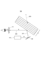
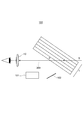
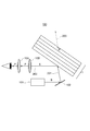
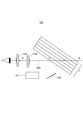
- FIG. 3 It is the schematic which shows one Embodiment of the optical laminated body which the image display system of this invention has. It is the schematic which shows one Embodiment of the polarization control part which the image display system of this invention has. It is a schematic schematic diagram which shows the 1st Embodiment of the head-up display system which comprises the image display system of this invention. In the head-up display system of FIG. 3, it is a schematic schematic diagram which shows the path of the light when the reflected light from a road surface is incident on an optical laminate. It is a schematic schematic diagram which shows the 2nd Embodiment of the head-up display system which comprises the image display system of this invention.
- FIG. 5 is a schematic schematic diagram showing a light path when the reflected light from the road surface is incident on the optical laminate in the head-up display system of FIG. It is a schematic schematic diagram which shows the 3rd Embodiment of the head-up display system which comprises the image display system of this invention. In the head-up display system of FIG. 7, it is a schematic schematic diagram which shows the path of the light when the reflected light from a road surface is incident on an optical laminate.
- the image display system of the present invention comprises (A) (a-1) an optical layer that converts the polarization direction of incident light by 90 °, and (a-2) an optical laminate containing at least one transparent resin substrate. (B) Display image projection means that emits S-polarized light to the optical laminate, (C) (c-1) P-polarized light control unit that transmits S-polarized light and blocks P-polarized light, or (c-2) incident.
- a polarization control unit having an S polarization control unit that converts the polarization direction of light by 90 ° and blocks S polarization is provided.
- the S-polarized light reflected by the optical laminate is incident on the polarization control unit, and the observer can visually recognize the image displayed on the optical laminate via the S-polarized light or P-polarized light transmitted through the polarization control unit. Therefore, the virtual image reflected by the observer of the optical laminate is visually recognized.
- the S-polarized light that has passed through the optical laminate is converted into P-polarized light by the optical layer, and the P-polarized light is transmitted to the outside of the optical laminate. As a result, the generation of double images can be significantly suppressed.
- the polarization control unit blocks the arrival of reflected light to the observer. As a result, a sufficient anti-glare effect and a clear visual recognition of the displayed image can be realized.
- the observer side of the optical laminate means one surface of the optical laminate close to the observer (visual viewer), that is, S-polarized light (hereinafter, also referred to as “display light”) from the display image projection means.
- the reachable side, the outside of the optical laminate is the other surface of the optical laminate far from the observer (viewer), that is, the S-polarized light from the display image projection means does not reach, and the light from the outside does not reach. It means the side to reach.
- the outside with respect to the observer (visual person) described later means the side where the polarized light from the optical laminate is incident on the polarization control unit.
- the optical laminate used in the image display system of the present invention includes an optical layer and at least one transparent resin base material.
- the optical laminate may further include at least one glass plate.
- FIG. 1 shows an embodiment of an optical laminate included in the image display system of the present invention.
- the optical laminate 1 is a transparent resin base material arranged on both sides of the optical layer 2 and the optical layer 2. 3 and glass plates 4 are further provided on both sides of the transparent resin base material 3.
- the optical laminate 1 can be manufactured, for example, by providing each transparent resin base material 3 on both sides of the optical layer 2 and sandwiching it between glass plates 4 and pressure-bonding it at high temperature and high pressure.
- the optical layer has a function of converting the polarization direction of incident light by 90 °, that is, a function of converting P-polarized light into S-polarized light or S-polarized light into P-polarized light.
- an optical rotation for example, a single 1/2 wave plate having a retardation value of 1/2 of a desired wavelength, or a laminate of a plurality of retardation plates, for example, 1/4 of two sheets. Examples include a laminated body of wave plates. Of these, the optical layer is preferably a 1/2 wave plate.
- the 1/2 wavelength plate is a retardation element having a function of converting P-polarized light into S-polarized light or S-polarized light into P-polarized light, that is, converting a polarization axis, and is made of, for example, a polycarbonate or cycloolefin polymer. It can be obtained by uniaxially stretching the film so that the retardation is 1/2 of the wavelength, or by orienting the horizontally oriented polymerizable liquid crystal to a thickness such that the retardation is 1/2 of the wavelength. it can.
- a 1/2 wave plate using a horizontally oriented polymerizable liquid crystal is supported by applying a polymerizable liquid crystal layer as a layer having an action of converting a polarization axis and a coating liquid forming the polymerizable liquid crystal layer. It is composed of a substrate.
- the upper limit of the thickness of such a 1/2 wave plate is preferably 10 ⁇ m or less, more preferably 5 ⁇ m or less, from the viewpoint of liquid crystal orientation.
- the lower limit of the thickness of the 1/2 wave plate is preferably 0.3 ⁇ m or more, more preferably 0.5 ⁇ m or more, from the viewpoint of the polymerizable property of the liquid crystal.
- the phase difference may change depending on the incident angle of the light.
- the in-plane refractive index of the retardation element is nx
- the in-plane refractive index of the retardation element is ny
- the in-plane refractive index of the retardation element is nz.
- the coefficient Nz represented by the following formula (1) is preferably controlled to be 0.3 or more and 1.0 or less, more preferably 0.5 or more and 0.8 or less.
- an image display device using such a 1/2 wave plate in order to efficiently convert S-polarized light to P-polarized light, a position inclined from an axis perpendicular to the surface of the optical laminate to 45 ° or more and 65 ° or less. It is preferable to control the angle ⁇ formed by the polarization axis of the S-polarized light incident from the above and the slow axis of the 1/2 wave plate to 35 ° or more and 47 ° or less.
- the incident angle of S-polarized light incident on the 1/2 wave plate in the range of 45 ° or more and 65 ° or less, the reflectance of P-polarized light can be theoretically suppressed to 2% or less, and the double image Occurrence can be suppressed.
- the incident S-polarized light is reflected on the surface of the optical laminate, and this S-polarized light reaches the observer.
- the transmitted S-polarized light is converted into P-polarized light by the 1/2 wave plate, and the converted P-polarized light is not reflected at the interface of the optical laminate on the incident side and the opposite side with air and passes through.
- the incident angle of the S-polarized light incident on the optical laminate in this way, it is possible to suppress the generation of a double image.
- the angle ⁇ is less than 35 ° or larger than 47 °
- the polarization axis conversion performance for converting S-polarized light incident on the optical laminate into P-polarized light is low, and as a result, the display image on the display becomes dark.
- the anti-glare effect may be impaired. Therefore, by appropriately controlling this angle ⁇ , the 1/2 wavelength plate exhibits good polarization axis conversion performance, and as a result, the displayed image can be visually recognized more clearly.
- the liquid crystal composition constituting the polymerizable liquid crystal layer is applied on the support substrate.
- a support substrate is preferably transparent in the visible light region in order to maintain the visibility of the displayed image when the 1/2 wave plate is used for HUD, and specifically, the wavelength is 380 nm or more and 780 nm.
- the following visible light transmittance may be 50% or more, preferably 70% or more, and more preferably 85% or more.
- the support substrate may be colored, but it is preferable that the support substrate is not colored or is less colored.
- the refractive index of the support substrate is preferably 1.2 or more and 2.0 or less, and more preferably 1.4 or more and 1.8 or less.
- the thickness of the support substrate may be appropriately selected depending on the intended use, and is preferably 5 ⁇ m or more and 1000 ⁇ m or less, more preferably 10 ⁇ m or more and 250 ⁇ m or less, and particularly preferably 15 ⁇ m or more and 150 ⁇ m or less.
- the support substrate may be a single layer or a laminated body having two or more layers.
- Examples of the material of the support substrate include triacetyl cellulose (TAC), acrylic, polycarbonate, polyvinyl chloride, polyolefin, polyethylene terephthalate (PET) and the like.
- TAC triacetyl cellulose
- PET polyethylene terephthalate
- TAC triacetyl cellulose
- polyolefin acrylic and the like having less birefringence are preferable.
- a method for producing a 1/2 wavelength plate using the above-mentioned nematic liquid crystal monomer having a polymerizable group will be described.
- a nematic liquid crystal monomer having a polymerizable group is dissolved in a solvent, and then a photopolymerization initiator is added.
- a solvent is not particularly limited as long as it can dissolve the liquid crystal monomer to be used, and examples thereof include cyclopentanone, toluene, methyl ethyl ketone, methyl isobutyl ketone and the like, and cyclopentanone and toluene are preferable.
- this solution is applied onto a plastic substrate such as a PET film or a TAC film used as a support substrate so that the thickness is as uniform as possible, and while the solvent is removed by heating, the solution is oriented as a liquid crystal on the support substrate. Let it stand for a certain period of time under such temperature conditions. At this time, before coating, the surface of the plastic substrate is subjected to a rubbing treatment in a desired orientation direction, or a photo-alignment material exhibiting photo-orientation by polarization irradiation is formed on the surface of the plastic substrate and subjected to an orientation treatment such as polarization irradiation. By setting it, the orientation of the liquid crystal can be made more uniform.
- the nematic liquid crystal monomer is irradiated with ultraviolet rays with a high-pressure mercury lamp or the like to fix the orientation of the liquid crystal, whereby a 1/2 wavelength plate having a desired slow-phase axis can be obtained. ..
- the main role of the 1/2 wave plate used as an optical layer is to convert the transmitted S-polarized light that is not reflected on the surface into P-polarized light. Thereby, it is possible to reduce the reflection from the transparent base material arranged on the outside of the optical laminate and suppress the generation of the double image. It is also to convert external light such as reflected light on the road surface into P-polarized light.
- the wavelength dispersibility of the 1/2 wave plate is not particularly limited, but it is preferably suitable for head-up display applications, and in particular, the 1/2 wave plate is reversed in order to accurately perform polarization conversion in a wide wavelength range in the visible light region. It is desirable to have wavelength dispersibility.
- a polymer has a normal dispersion in which the absolute value of birefringence increases on the short wavelength side, but a liquid crystal in which the birefringence increases on the long wavelength side by controlling the value of birefringence ⁇ n at each wavelength of visible light. If it is a compound, reverse wavelength dispersibility can be obtained. Inverse wavelength dispersibility can also be obtained by laminating a plurality of retardation plates having appropriate retardation values according to the wavelength dispersion characteristics of the liquid crystal compound in an appropriate combination of slow phase axes.
- the 1/2-wave plate as an optical layer of the S-polarized light and the 1/2-wave plate that are incident in a state of being inclined at Brewster's angle. It is preferable that they are arranged in a positional relationship in which the angle with the slow axis is within the range of 45 ° ⁇ 3 °, and the angle is more preferably within the range of 45 ° ⁇ 2 ° 45 ° ⁇ 1. It is more preferably in the range of °.
- the optical laminate has at least one transparent resin base material, and preferably has two transparent resin base materials. In this case, it is preferable that the optical layer is sandwiched between two transparent resin base materials.
- the two transparent resin substrates may be the same or different from each other, but are preferably the same.
- the transparent resin base material is not particularly limited, but is preferably suitable for head-up display applications, and in this case, there are certain restrictions on the visible light transmittance and the haze value.
- the visible light transmittance is preferably 70% or more, more preferably 75% or more, further preferably 80% or more, particularly preferably 85% or more, and 90% or more. Most preferably.
- the haze value is preferably 2% or less, more preferably 1% or less, and even more preferably 0.5% or less. Further, it is preferable that the transparent resin base material does not have optical anisotropy.
- the thickness of the transparent resin base material is preferably 0.5 mm or more and 25 mm or less.
- the upper limit of the thickness of the transparent resin base material is more preferably 20 mm, further preferably 15 mm.
- the lower limit of the thickness of the transparent resin base material is more preferably 0.6 mm, further preferably 0.7 mm.
- the transparent resin base material include cyclic polyolefins, polyether sulfone, polyarylate, polyethylene terephthalate, polycarbonate resins, acrylic resins such as polymethylmethacrylate, ABS (acrylonitrile-butadiene-styrene) resins, polyphenylene ether resins, and the like. Can be mentioned. Of these, polycarbonate resin, polymethylmethacrylate resin, and polyvinyl butyral are preferable.
- the transparent resin base material may be one type alone or a laminated body having two or more layers.
- polycarbonate resin is preferable because it has excellent transparency, high impact absorption, improved safety in the event of a collision, and excellent impact resistance and is not easily damaged in a light collision.
- the polycarbonate resin, acrylic resin, cyclic polyolefin resin, polyphenylene ether resin and the like can be used as a resin composition by blending a thermoplastic resin other than the main component resin as long as the characteristics of the present invention are not impaired.
- the transparent resin base material is preferably polyvinyl butyral. The case where the glass plate (a-3) is arranged on one side of the optical laminate is expressed as support, and the case where the glass plate is arranged on both sides is expressed as sandwiching.
- the optical laminate layer may further have a glass plate, or may be used as functional glass supported or sandwiched by the glass plate.
- the glass plate is not particularly limited as long as the front view is sufficiently visible and transparent even if the functional glass is used as the windshield.
- the refractive index of the glass plate is preferably 1.2 or more and 2.0 or less, and more preferably 1.4 or more and 1.8 or less.
- the thickness, shape, and the like of the glass plate are not particularly limited as long as they do not affect the reflection of the display light, and can be appropriately designed according to the application.
- these glass plates may be provided with an antireflection film made of a multilayer film, a metal thin film having a heat shielding function, or the like on the reflecting surface.
- the glass plate also includes curved glass such as a windshield.
- thermoplastic resin As a method of adhering the optical laminate layer to the glass plate, for example, a thermoplastic resin is used as a transparent resin base material, the optical layer is sandwiched between two thermoplastic resins, and further sandwiched between two pieces of glass.
- the method of crimping at high temperature and high pressure is preferable.
- the thermoplastic resin for example, polyvinyl butyral resin (PVB), polyvinyl alcohol resin (PVA) or ethylene-vinyl acetate copolymer resin (EVA) is preferable, and PVB is more preferable.
- the thickness and hardness of the two transparent resin base materials are not particularly limited as long as they do not affect the reflection of the display light, and are UV-cut, heat-shielded, sound-insulated or dimmed depending on the application. And other functions can be designed as appropriate. Further, the thickness and hardness of the two transparent resin substrates may be the same or different from each other, but are preferably different.
- the functional glass thus obtained can be used as the windshield, side glass, rear glass, and roof glass of large special vehicles and small special vehicles in all of ordinary automobiles, small automobiles, and light automobiles.
- functional glass can be used as windows for railroad vehicles, ships and aircraft, as well as for building and industrial windows.
- the form of use of the functional glass it can be used by laminating or laminating with a member having at least one function of a UV blocking function, a heat insulating function, a sound insulating function and a dimming function.
- the display image projection means used in the image display system including the display image projection means that emits S-polarized light has a Brewster's angle of incidence on the surface of the optical laminate.
- the S-polarized display light is emitted so that the angle is close to the angle.
- the angle near the Brewster angle means that the incident angle of S-polarized light incident on the optical laminate is ⁇ -10 ° or more and ⁇ + 10 °, where ⁇ is the Brewster angle of S-polarized light with respect to the surface of the optical laminate. It means that it is in the following range.
- the S-polarized light from the display image projection means When the S-polarized light from the display image projection means is incident on the optical laminate at an angle near the Brewster's angle, most of the S-polarized light is reflected and reaches the observer, so that the observer can visually recognize the virtual image.
- the S-polarized light that cannot be reflected on the surface of the optical laminate and is transmitted through the optical laminate is converted into P-polarized light by the optical layer, and the converted P-polarized light is transmitted through the optical laminate.
- the light reaching the display image projection means is S-polarized light
- the light emitted from the display image projection means may be P-polarized light. In this case, since it is necessary to convert the emitted P-polarized light into S-polarized light, for example, it is preferable to provide a 1/2 wavelength plate before the P-polarized light reaches the optical laminate.
- the image display system of the present invention has a P-polarization control unit that transmits (c-1) S-polarized light and blocks P-polarized light, or (c-2) a polarization direction of incident light of 90 °.
- a polarization control unit having an S polarization control unit that converts and blocks S polarization is provided.
- a P-polarized light control unit that transmits S-polarized light and blocks P-polarized light for example, polarized sunglasses produced by making the absorption axis of the polarizing filter vertical so that the lens itself transmits S-polarized light and blocks P-polarized light.
- a polarizing film in which the absorption axis of the polarizing filter is vertical so as to transmit S-polarized light and block P-polarized light can be mentioned.
- the S polarization control unit has (c-2a) a retardation film that converts the polarization direction of the incident light by 90 °, that is, converts P-polarized light into S-polarized light or S-polarized light into P-polarized light.
- a retardation film examples include a 1/2 wavelength plate.
- the S polarization control unit preferably has a polarizing film that blocks S-polarized light or polarized sunglasses that block S-polarized light, in addition to the retardation film.
- the polarizing film that blocks S-polarized light examples include a polarizing film whose absorption axis is horizontal to the reflected light from the road surface, that is, the polarization axis of S-polarized light incident on the polarizing film.
- examples of polarized sunglasses that block S-polarized light include polarized sunglasses in which the absorption axis of the polarizing filter is horizontal to the polarization axis of S-polarized light incident on the polarizing filter.
- the S polarization control unit preferably has (c-2a) a retardation film that converts the polarization direction of the incident light by 90 ° and (c-2b) a polarizing film that blocks S polarization.
- the S polarization control unit may be a laminate of the retardation film and the polarizing film that blocks S polarization, and these may be arranged separately.
- the retardation film and the polarizing film are arranged in this order from the outside with reference to the observer.
- FIG. 2 is a schematic view showing an embodiment of a polarization control unit included in the image display system of the present invention.
- the polarization control unit 10 is an S polarization control unit including a retardation film 10B and a polarizing film 10A that blocks S polarization.
- the retardation film 10B is arranged outside the polarizing film 10A with reference to the observer. Therefore, the retardation film 10B converts the polarization direction of the polarized light incident on the polarization control unit 10 by 90 °.
- the S-polarized light When the converted polarized light is S-polarized light, the S-polarized light is blocked by the polarizing film 10A, and when the converted polarized light is P-polarized light, the P-polarized light passes through the polarizing film 10A and reaches the observer.
- the retardation film 10B and the polarizing film 10A are arranged apart from each other, but the polarization control unit 10 is a laminate of the retardation film 10B and the polarizing film 10A. It may be.
- the retardation film 10B and the polarizing film 10A are arranged apart from each other
- eyewear in which the retardation film 10B is arranged on the visor and the polarizing film 10A is provided is used.
- a method of attaching the retardation film 10B to general polarized sunglasses with a clip (clip-on type) can be mentioned.
- the polarization control unit 10 is a laminate of the retardation film 10B and the polarizing film 10A, for example, a composite film in which the retardation film 10B and the polarizing film 10A are bonded together via an adhesive or an adhesive. Can be exemplified in the use of the above for eyewear.
- the S polarization control unit is a combination of a 1/2 wavelength plate as a retardation film and a polarizing film whose absorption axis is horizontal to the polarization axis of S polarization incident on the polarizing film
- the displayed image is visually recognized.
- the method include a method in which a composite film in which these are laminated or laminated is attached to an in-vehicle visor or eyewear, and a displayed image is visually recognized via the composite film.
- a 1/2 wavelength plate as a retardation film is attached to the in-vehicle visor
- a polarizing film is attached to the eyewear, and an image displayed by the eyewear via the 1/2 wavelength plate provided in the in-vehicle visor.
- the S polarization control unit is a combination of a 1/2 wave plate as a retardation film and polarized sunglasses in which the absorption axis of the polarizing filter is horizontal to the polarization axis of S polarization incident on the polarizing filter, the polarized light is polarized.
- a method of providing the 1/2 wavelength plate on the sunglasses for example, a method of wearing a sunglasses having a 1/2 wavelength plate as an overglass on a general polarized sunglasses, or a method of attaching a clip on a general polarized sunglasses.
- a method (clip-on type) and the like can be mentioned.
- the overglass attachment and clip-on type are preferable because it is easy to switch the polarization cutoff between when the displayed image is visually recognized and in normal times other than that, and a normal antiglare effect can be obtained in normal times. In particular, in the case of the clip-on type, switching the polarization cutoff becomes easier by opening and closing the clip.
- a method of attaching a film containing a 1/2 wavelength plate to the surface of general polarized sunglasses via an adhesive or an adhesive can also be used.
- the adhesive and the adhesive are not particularly limited, but when the 1/2 wave plate can be attached and detached, an adhesive having excellent reworkability is preferable, and for example, a silicone adhesive having excellent transparency and an acrylic type. Adhesives and the like are preferred.
- the S-polarized light is converted to P-polarized light.
- the angle ⁇ is less than 35 ° or larger than 47 °, the polarization axis conversion performance for converting S-polarized light incident on the 1/2 wavelength plate into P-polarized light is low, and as a result, the displayed image on the display becomes dark.
- the anti-glare effect may be impaired. Therefore, by appropriately controlling this angle ⁇ , the 1/2 wavelength plate exhibits good polarization axis conversion performance, and as a result, the displayed image can be visually recognized more clearly.
- the wavelength dispersibility of the 1/2 wave plate is not particularly limited as long as it is suitable for eyewear applications, but it must have inverse wavelength dispersibility in order to accurately perform polarization conversion in a wide wavelength range in the visible light region. Is desirable.
- FIG. 3 is a schematic schematic diagram showing an embodiment of a head-up display system including the image display system of the present invention.
- the HUD system (image display system) 100 of the present embodiment is emitted from the display image projection means 101 that emits S-polarized light as the display light indicating the display image and the display image projection means 101.
- It includes an optical laminate 1 on which S-polarized light is incident, and a polarization control unit 10'as a P-polarization control unit.
- the S-polarized light emitted from the display image projection means 101 is reflected by the reflector 102, and the reflected display light reaches the optical laminate 1.
- the optical laminate 1 has an optical layer 2, transparent resin base materials 3 on both sides thereof, and glass plates 4 on both outer sides thereof.
- the S-polarized incident light 201 emitted from the display image projection means 101 is incident on the optical laminate 1 at an incident angle near the Brewster angle.
- the incident light 201 is reflected at the interface between the surface of the optical laminate 1 on the observer side and the air, and the reflected light 202 is generated. Since the reflected light 202 is S-polarized light, the S-polarized light is transmitted as it is even if the polarization control unit 10'having the P-polarized light control unit that blocks the P-polarized light is used. Therefore, the passed reflected light 202 is visually recognized by the observer as a display image.
- the incident light 201 that is not reflected as the reflected light 202 and is incident on the optical laminate 1 propagates in the optical laminate 1 and is converted into P-polarized light by the optical layer 2.
- the incident light 201 converted to P-polarized light propagates at the interface between the glass plate 4 arranged outside the optical laminate 1 and the air near the Brewster's angle. Therefore, the reflected light at the interface becomes substantially 0, and the incident light 201 converted to P-polarized light passes through the optical laminate 1 as transmitted light 203.
- FIG. 4 shows the path of light when the reflected light from the road surface is incident on the optical laminate in the HUD system (image display system) 100 of FIG. Since the reflected light from the road surface contains a large amount of S-polarized light, S-polarized light is incident from the outside of the optical laminate 1.
- the incident S-polarized light propagates in the optical laminate 1 and is converted into P-polarized light by the optical layer 2.
- the incident light 204 converted into P-polarized light further propagates in the optical laminated body 1 and passes through the optical laminated body 1, the incident light 204 is transmitted by the polarization control unit 10'having a P-polarized light control unit that blocks P-polarized light. It is not blocked by the polarization control unit 10'. Therefore, the transmitted light becomes substantially 0, and the reflected light from the outside (outside the vehicle) does not reach the observer.
- FIG. 5 is a schematic schematic diagram showing another embodiment of the head-up display system including the image display system of the present invention.
- the HUD system (image display system) 100 of the present embodiment is emitted from the display image projection means 101 that emits S-polarized light as the display light indicating the display image and the display image projection means 101.
- An optical laminate 1 to which S-polarized light is incident, and a retardation film 10B for converting the polarization direction of the incident light by 90 ° and a polarizing film 10A for blocking S-polarized light are provided as an S-polarized light control unit.
- the retardation film 10B and the polarizing film 10A are arranged separately, and the retardation film 10B is outside the polarizing film 10A with respect to the observer, that is, the polarized light from the optical laminate 1 is polarized. It is located on the incident side. Similar to FIG. 3, the S-polarized light emitted from the display image projection means 101 is reflected by the reflector 102, and the reflected display light reaches the optical laminate 1. As shown in FIG. 1, the optical laminate 1 has an optical layer 2, transparent resin base materials 3 on both sides thereof, and glass plates 4 on both outer sides thereof.
- the S-polarized incident light 201 emitted from the display image projection means 101 is incident on the optical laminate 1 at an incident angle near the Brewster angle.
- the incident light 201 is reflected at the interface between the surface of the optical laminate 1 on the observer side and the air, and the reflected light 202 is generated. Since the reflected light 202 is S-polarized light, the reflected light 202 is converted to P-polarized light by the retardation film 10B.
- the reflected light 202 converted to P-polarized light transmits the P-polarized light as it is even if the polarizing film 10A that blocks S-polarized light is used. Therefore, the passed reflected light 202 is visually recognized by the observer as a display image.
- the incident light 201 that is not reflected as the reflected light 202 and is incident on the optical laminate 1 propagates in the optical laminate 1 and is converted into P-polarized light by the optical layer 2.
- the incident light 201 converted to P-polarized light propagates at the interface between the glass plate 4 arranged outside the optical laminate 1 and the air near the Brewster's angle. Therefore, the reflected light at the interface becomes substantially 0, and the incident light 201 converted to P-polarized light passes through the optical laminate 1 as transmitted light 203.
- FIG. 6 shows the path of light when the reflected light from the road surface is incident on the optical laminate in the HUD system (image display system) 100 of FIG. Similar to FIG. 4, since the reflected light from the road surface contains a large amount of S-polarized light, S-polarized light is incident from the outside of the optical laminate 1.
- the incident S-polarized light propagates in the optical laminate 1 and is converted into P-polarized light by the optical layer 2.
- the transmitted light 204 converted to P-polarized light further propagates in the optical laminated body 1 and passes through the optical laminated body 1, the transmitted light 204 is P-polarized and is converted to S-polarized light by the retardation film 10B.
- the transmitted light 204 converted to S-polarized light is blocked by the polarizing film 10A that blocks S-polarized light. Therefore, the transmitted light becomes substantially 0, and the reflected light from the outside (outside the vehicle) does not reach the observer.
- FIG. 7 is a schematic schematic diagram showing an embodiment of a head-up display system including the image display system of the present invention.
- the HUD system (image display system) 100 of the present embodiment is emitted from the display image projection means 101 that emits S-polarized light as the display light indicating the display image and the display image projection means 101.
- It includes an optical laminate 1 on which S-polarized light is incident, and a polarization control unit 10 in which a retardation film 10B and a polarizing film 10A are directly laminated as an S-polarization control unit.
- the retardation film 10B is arranged outside the polarizing film 10A with reference to the observer, that is, on the side where the polarized light from the optical laminate 1 is incident.
- the S-polarized light emitted from the display image projection means 101 is reflected by the reflector 102, and the reflected display light reaches the optical laminate 1.
- the optical laminate 1 has an optical layer 2, transparent resin base materials 3 on both sides thereof, and glass plates 4 on both outer sides thereof.
- the S-polarized incident light 201 emitted from the display image projection means 101 is incident on the optical laminate 1 at an incident angle near the Brewster angle.
- the incident light 201 is reflected at the interface between the surface of the optical laminate 1 on the observer side and the air, and the reflected light 202 is generated.
- the reflected light 202 is S-polarized light, it is converted into P-polarized light by the retardation film 10B in the polarization control unit 10 which is a laminate of the retardation film 10B and the polarizing film 10A.
- the reflected light 202 converted to P-polarized light is transmitted as P-polarized light through the polarizing film 10A that blocks S-polarized light. Therefore, the passed reflected light 202 is visually recognized by the observer as a display image.
- the incident light 201 that is not reflected as the reflected light 202 and is incident on the optical laminate 1 propagates in the optical laminate 1 and is converted into P-polarized light by the optical layer 2.
- the incident light 201 converted to P-polarized light propagates at the interface between the glass plate 4 arranged outside the optical laminate 1 and the air near the Brewster's angle. Therefore, the reflected light at the interface becomes substantially 0, and the incident light 201 converted to P-polarized light passes through the optical laminate 1 as transmitted light 203.
- FIG. 8 shows the path of light when the reflected light from the road surface is incident on the optical laminate in the HUD system (image display system) 100 of FIG. Similar to FIG. 4, since the reflected light from the road surface contains a large amount of S-polarized light, S-polarized light is incident from the outside of the optical laminate 1. The incident S-polarized light propagates in the optical laminate 1 and is converted into P-polarized light by the optical layer 2.
- the transmitted light 204 is P-polarized light, so that the laminated body of the retardation film 10B and the polarizing film 10A In a certain polarization control unit 10, it is converted into S polarization by the retardation film 10B.
- the transmitted light 204 converted to S-polarized light is blocked by the polarizing film 10A that blocks S-polarized light. Therefore, the transmitted light becomes substantially 0, and the reflected light from the outside (outside the vehicle) does not reach the observer.
- the image display system of the present invention can visually recognize the displayed image without discomfort even in a head-up display of a type using S-polarized light, and on the other hand, a sufficient antiglare effect against external light can be secured. Therefore, it is possible to visually recognize a clear display image while ensuring an antiglare effect against incident light from the outside.
- Such an image display system is useful for application to a head-up display system. Further, since the layer structure of the optical laminate is not complicated, it can contribute to the simplification of the manufacturing process.
- Optical laminate 2 Optical layer 3: Transparent resin base material 4: Glass plate 10, 10': Polarization control unit 10A: Polarizing film 10B: Phase difference film 100: Head-up display system, image display system 101: Display image Projection means 102: Reflector 201: Incident light 202: Reflected light 203, 204: Transmitted light
Landscapes
- Physics & Mathematics (AREA)
- Engineering & Computer Science (AREA)
- General Physics & Mathematics (AREA)
- Optics & Photonics (AREA)
- Mechanical Engineering (AREA)
- Transportation (AREA)
- Combustion & Propulsion (AREA)
- Chemical & Material Sciences (AREA)
- Health & Medical Sciences (AREA)
- Ophthalmology & Optometry (AREA)
- General Health & Medical Sciences (AREA)
- Instrument Panels (AREA)
- Polarising Elements (AREA)
Abstract
Description
1)
(A)(a-1)入射した光の偏光方向を90°変換させる光学層、及び(a-2)少なくとも1つの透明樹脂基材を含む光学積層体と、
(B)前記光学積層体にS偏光を出射する表示画像投影手段と、
(C)(c-1)S偏光を透過し、P偏光を遮断するP偏光制御部、又は(c-2)入射した光の偏光方向を90°変換し、S偏光を遮断するS偏光制御部を有する偏光制御部と、を備え、
前記光学積層体で反射したS偏光が前記偏光制御部に入射されるヘッドアップディスプレイ用画像表示システム。
2)
前記光学層が1/2波長板である、上記1)に記載の画像表示システム。
3)
前記光学積層体が、さらに(a-3)少なくとも1つのガラス板を有する、上記1)又は2)に記載の画像表示システム。
4)
前記偏光制御部がS偏光制御部を有する、上記1)乃至3)のいずれか一つに記載の画像表示システム。
5)
前記S偏光制御部が、(c-2a)入射した光の偏光方向を90°変換させる位相差フィルムを有する、上記4)に記載の画像表示システム。
6)
前記S偏光制御部が、(c-2a)入射した光の偏光方向を90°変換させる位相差フィルムと(c-2b)S偏光を遮断する偏光フィルムとを有する、上記4)に記載の画像表示システム。
7)
前記位相差フィルムが1/2波長板である、上記6)に記載の画像表示システム。
8)
前記S偏光制御部が、前記位相差フィルムと前記偏光フィルムとの積層体である、上記6)又は7)に記載の画像表示システム。
9)
前記位相差フィルムと前記偏光フィルムが、観察者を基準として外側からこの順序で配置されている、上記6)乃至8)のいずれか一つに記載の画像表示システム。
10)
前記偏光制御部がアイウェアに備えられている、上記1)乃至9)のいずれか一つに記載の画像表示システム。
11)
前記偏光制御部が自動車内バイザーに備えられている、上記1)乃至9)のいずれか一つに記載の画像表示システム。
12)
前記位相差フィルムが自動車内バイザーに備えられ、前記偏光フィルムがアイウェアに備えられている、上記6)又は7)に記載の画像表示システム。
13)
前記光学層が、ブリュースター角に傾斜した状態で入射するS偏光の偏光軸と前記光学層の遅相軸との角度が45°±3°の範囲内である位置関係で配置されている、上記1)乃至12)のいずれか一つに記載の画像表示システム。
14)
上記1)乃至13)のいずれか一つに記載の画像表示システムを備えるヘッドアップディスプレイシステム。
本発明の画像表示システムに使用される光学積層体は、光学層と、少なくとも1つの透明樹脂基材とを備える。光学積層体は、更に少なくとも1つのガラス板を備えていてもよい。図1には、本発明の画像表示システムが有する光学積層体の一実施形態が示されており、光学積層体1は、光学層2と、光学層2の両面に配置された透明樹脂基材3とを有しており、透明樹脂基材3の両面には更にガラス板4が設けられている。光学積層体1は、例えば、光学層2の両面に各透明樹脂基材3を設け、ガラス板4で挟み高温・高圧にて圧着し、作製することができる。
光学層は、入射した光の偏光方向を90°変換させる機能、すなわち、P偏光をS偏光に、又はS偏光をP偏光に変換する機能を有する。このような機能を有する光学層として、旋光子、例えば位相差値が所望の波長の1/2である1/2波長板単体、複数の位相差板の積層体、例えば2枚の1/4波長板の積層体等が挙げられる。これらのうち、光学層は1/2波長板であることが好ましい。
1/2波長板は、P偏光をS偏光に、又はS偏光をP偏光に変換する、すなわち偏光軸を変換する機能を持つ位相差素子であり、例えば、ポリカーボネート又はシクロオレフィンポリマーで作製されたフィルムを位相差が波長の1/2となるように一軸延伸したり、水平配向する重合性液晶を位相差が波長の1/2となるような厚さで配向させたりすることによって得ることができる。一般に、水平配向する重合性液晶を使用した1/2波長板は、偏光軸を変換させる作用を有する層としての重合性液晶層と、当該重合性液晶層を形成する塗布液が塗布される支持基板とから構成されている。このような1/2波長板の厚みの上限値は、液晶の配向性の観点から10μm以下が好ましく、5μm以下がより好ましい。一方、1/2波長板の厚みの下限値は、液晶の重合性の観点から0.3μm以上が好ましく、0.5μm以上がより好ましい。光が1/2波長板の表面に対して斜めの位置から入射する場合、光の入射角によって位相差が変化する場合がある。このような場合、より厳密に位相差を適合させるため、例えば、位相差素子の屈折率を調整した位相差素子を用いることにより、入射角に伴う位相差の変化を抑制することができる。例えば、位相差素子の面内での遅相軸方向の屈折率をnx、位相差素子の面内でnxと直交する方向の屈折率をny、位相差素子厚さ方向の屈折率をnzとするとき、下記式(1)で示される係数Nzが、好ましくは0.3以上1.0以下、より好ましくは0.5以上0.8以下となるように制御する。

光学積層体は、少なくとも1つの透明樹脂基材を有し、好ましくは2枚の透明樹脂基材を有する。この場合、光学層が2枚の透明樹脂基材で挟持されていることが好ましい。2枚の透明樹脂基材は互いに同じであっても異なっていてもよいが、同じであることが好ましい。透明樹脂基材は特に制限はないが、ヘッドアップディスプレイ用途に適することが好ましく、この場合、可視光透過率、ヘイズ値については一定の制約がある。例えば、可視光透過率は70%以上であることが好ましく、75%以上であることがより好ましく、80%以上であることが更に好ましく、85%以上であることが特に好ましく、90%以上であることが最も好ましい。また、ヘイズ値は2%以下であることが好ましく、1%以下であることがより好ましく、0.5%以下であることが更に好ましい。また、透明樹脂基材は光学異方性を有していないことが好ましい。
光学積層体層は更にガラス板を有していてもよく、ガラス板で支持又は挟持された機能性ガラスとして使用してもよい。ガラス板は、例えば、機能性ガラスをフロントガラスとして利用しても、前方の景色が十分に視認可能な透明性があれば特に限定されるものではない。また、ガラス板の屈折率は1.2以上2.0以下であることが好ましく、1.4以上1.8以下であることがより好ましい。また、ガラス板の厚み、形状等も、表示光の反射に影響を与えない範囲であれば、特に限定されるものではなく、用途に応じて適宜設計することができる。また、これらガラス板には反射面に多層膜からなる増反射膜、遮熱機能をも兼ねる金属薄膜等が設けられていてもよい。これらの膜は入射する偏光の反射率を向上させることができるが、自動車用フロントガラスとして、機能性ガラスを用いる場合は、機能性ガラスの可視光線透過率が70%以上となるように反射率を調整することが好ましい。なお、ガラス板には、例えばウインドシールドの様な曲面形状のガラスも含まれる。
本発明の画像表示システムは、S偏光を出射する表示画像投影手段を備える画像表示システムに使用される表示画像投影手段は、光学積層体の表面に対する入射角がブリュースター角近傍の角度になるようにS偏光の表示光を出射する。ここで、ブリュースター角近傍の角度とは、光学積層体の表面に対するS偏光のブリュースター角をαとしたとき、光学積層体に入射するS偏光の入射角が、α-10°以上α+10°以下の範囲であることを意味する。表示画像投影手段からのS偏光がブリュースター角近傍の角度で光学積層体に入射すると、多くのS偏光は反射し、観察者に到達するため、観察者は虚像を視認することができる。一方、光学積層体の表面で反射できずに光学積層体を透過したS偏光は、光学層でP偏光に変換され、変換されたP偏光は光学積層体を透過する。その結果、光学積層体の外側からの反射が防止され、二重像の発生を抑制することができる。なお、表示画像投影手段に到達する光がS偏光であれば、表示画像投射手段から出射される光はP偏光であってもよい。この場合、出射されたP偏光をS偏光へ変換する必要があるため、例えば、光学積層体にP偏光が到達する前に1/2波長板を備えることが好ましい。
本発明の画像表示システムは、(c-1)S偏光を透過し、P偏光を遮断するP偏光制御部、又は(c-2)入射した光の偏光方向を90°変換し、S偏光を遮断するS偏光制御部を有する偏光制御部を備える。S偏光を透過し、P偏光を遮断するP偏光制御部として、例えば、レンズ自体がS偏光を透過し、P偏光を遮断するように偏光フィルターの吸収軸を垂直にしてレンズを作製した偏光サングラス、又は、S偏光を透過し、P偏光を遮断するように偏光フィルターの吸収軸を垂直にした偏光フィルム等が挙げられる。
図3は本発明の画像表示システムを備えるヘッドアップディスプレイシステムの一実施形態を示す概略模式図である。図3で示されるように、本実施形態のHUDシステム(画像表示システム)100は、表示画像を示す表示光としてS偏光を出射する表示画像投影手段101と、表示画像投影手段101から出射されたS偏光が入射される光学積層体1と、P偏光制御部として偏光制御部10’とを備えている。表示画像投影手段101から出射したS偏光を反射鏡102で反射させ、この反射された表示光が光学積層体1に到達する。光学積層体1は、図1に示されるように、光学層2と、その両側に透明樹脂基材3、更にその両外側にガラス板4とを有している。
図5は本発明の画像表示システムを備えるヘッドアップディスプレイシステムの他の実施形態を示す概略模式図である。図5で示されるように、本実施形態のHUDシステム(画像表示システム)100は、表示画像を示す表示光としてS偏光を出射する表示画像投影手段101と、表示画像投影手段101から出射されたS偏光が入射する光学積層体1と、S偏光制御部として、入射した光の偏光方向を90°変換させる位相差フィルム10B及びS偏光を遮断する偏光フィルム10Aとを備えている。図5では、位相差フィルム10Bと偏光フィルム10Aとはそれぞれ別々に配置されており、位相差フィルム10Bは、観察者を基準として偏光フィルム10Aよりも外側、すなわち、光学積層体1からの偏光が入射する側に配置されている。図3と同様、表示画像投影手段101から出射したS偏光を反射鏡102で反射させ、この反射された表示光が光学積層体1に到達する。光学積層体1は、図1に示されるように、光学層2と、その両側に透明樹脂基材3、更にその両外側にガラス板4とを有している。
図7は本発明の画像表示システムを備えるヘッドアップディスプレイシステムの一実施形態を示す概略模式図である。図7で示されるように、本実施形態のHUDシステム(画像表示システム)100は、表示画像を示す表示光としてS偏光を出射する表示画像投影手段101と、表示画像投影手段101から出射されたS偏光が入射される光学積層体1と、S偏光制御部として、位相差フィルム10Bと偏光フィルム10Aとが直接積層された偏光制御部10とを備えている。偏光制御部10において、位相差フィルム10Bは、観察者を基準として偏光フィルム10Aよりも外側、すなわち、光学積層体1からの偏光が入射する側に配置されている。表示画像投影手段101から出射したS偏光を反射鏡102で反射させ、この反射された表示光が光学積層体1に到達する。光学積層体1は、図1に示されるように、光学層2と、その両側に透明樹脂基材3、更にその両外側にガラス板4とを有している。
2:光学層
3:透明樹脂基材
4:ガラス板
10,10’:偏光制御部
10A:偏光フィルム
10B:位相差フィルム
100:ヘッドアップディスプレイシステム、画像表示システム
101:表示画像投影手段
102:反射鏡
201:入射光
202:反射光
203,204:透過光
Claims (14)
- (A)(a-1)入射した光の偏光方向を90°変換させる光学層、及び(a-2)少なくとも1つの透明樹脂基材を含む光学積層体と、
(B)前記光学積層体にS偏光を出射する表示画像投影手段と、
(C)(c-1)S偏光を透過し、P偏光を遮断するP偏光制御部、又は(c-2)入射した光の偏光方向を90°変換し、S偏光を遮断するS偏光制御部を有する偏光制御部と、を備え、
前記光学積層体で反射したS偏光が前記偏光制御部に入射される画像表示システム。 - 前記光学層が1/2波長板である、請求項1に記載の画像表示システム。
- 前記光学積層体が、さらに(a-3)少なくとも1つのガラス板を有する、請求項1又は2に記載の画像表示システム。
- 前記偏光制御部がS偏光制御部を有する、請求項1乃至3のいずれか一項に記載の画像表示システム。
- 前記S偏光制御部が、(c-2a)入射した光の偏光方向を90°変換させる位相差フィルムを有する、請求項4に記載の画像表示システム。
- 前記S偏光制御部が、(c-2a)入射した光の偏光方向を90°変換させる位相差フィルムと(c-2b)S偏光を遮断する偏光フィルムとを有する、請求項4に記載の画像表示システム。
- 前記位相差フィルムが1/2波長板である、請求項6に記載の画像表示システム。
- 前記S偏光制御部が、前記位相差フィルムと前記偏光フィルムとの積層体である、請求項6又は7に記載の画像表示システム。
- 前記位相差フィルムと前記偏光フィルムが、観察者を基準として外側からこの順序で配置されている、請求項6乃至8のいずれか一項に記載の画像表示システム。
- 前記偏光制御部がアイウェアに備えられている、請求項1乃至9のいずれか一項に記載の画像表示システム。
- 前記偏光制御部が自動車内バイザーに備えられている、請求項1乃至9のいずれか一項に記載の画像表示システム。
- 前記位相差フィルムが自動車内バイザーに備えられ、前記偏光フィルムがアイウェアに備えられている、請求項6又は7に記載の画像表示システム。
- 前記光学層が、ブリュースター角に傾斜した状態で入射するS偏光の偏光軸と前記光学層の遅相軸との角度が45°±3°の範囲内である位置関係で配置されている、請求項1乃至12のいずれか一項に記載の画像表示システム。
- 請求項1乃至13のいずれか一項に記載の画像表示システムを備えるヘッドアップディスプレイシステム。
Priority Applications (4)
| Application Number | Priority Date | Filing Date | Title |
|---|---|---|---|
| CN202080062992.4A CN114341709B (zh) | 2019-09-11 | 2020-08-26 | 图像显示系统及抬头显示器系统 |
| EP20864151.4A EP4030218B1 (en) | 2019-09-11 | 2020-08-26 | Image display system and head-up display system |
| JP2021506587A JP6972423B2 (ja) | 2019-09-11 | 2020-08-26 | 画像表示システム及びヘッドアップディスプレイシステム |
| US17/653,725 US20220187602A1 (en) | 2019-09-11 | 2022-03-07 | Image display system and head-up display system |
Applications Claiming Priority (2)
| Application Number | Priority Date | Filing Date | Title |
|---|---|---|---|
| JP2019164997 | 2019-09-11 | ||
| JP2019-164997 | 2019-09-11 |
Related Child Applications (1)
| Application Number | Title | Priority Date | Filing Date |
|---|---|---|---|
| US17/653,725 Continuation US20220187602A1 (en) | 2019-09-11 | 2022-03-07 | Image display system and head-up display system |
Publications (1)
| Publication Number | Publication Date |
|---|---|
| WO2021049295A1 true WO2021049295A1 (ja) | 2021-03-18 |
Family
ID=74866033
Family Applications (1)
| Application Number | Title | Priority Date | Filing Date |
|---|---|---|---|
| PCT/JP2020/032121 Ceased WO2021049295A1 (ja) | 2019-09-11 | 2020-08-26 | 画像表示システム及びヘッドアップディスプレイシステム |
Country Status (5)
| Country | Link |
|---|---|
| US (1) | US20220187602A1 (ja) |
| EP (1) | EP4030218B1 (ja) |
| JP (1) | JP6972423B2 (ja) |
| CN (1) | CN114341709B (ja) |
| WO (1) | WO2021049295A1 (ja) |
Cited By (3)
| Publication number | Priority date | Publication date | Assignee | Title |
|---|---|---|---|---|
| CN114594604A (zh) * | 2022-03-09 | 2022-06-07 | 江苏泽景汽车电子股份有限公司 | 重影消减方法及抬头显示系统 |
| WO2024058138A1 (ja) * | 2022-09-12 | 2024-03-21 | 日本化薬株式会社 | ヘッドアップディスプレイシステム及びヘッドアップディスプレイ用光学機能層 |
| EP4486586A4 (en) * | 2022-03-04 | 2026-03-18 | Xinyu Zhu | METHOD FOR IMPROVING THE READABILITY OF AN INTERNAL DISPLAY DEVICE IN MOTORIZED OBJECTS AND ASSOCIATED SYSTEM |
Families Citing this family (2)
| Publication number | Priority date | Publication date | Assignee | Title |
|---|---|---|---|---|
| DE102023118321A1 (de) | 2023-07-11 | 2025-01-16 | Bayerische Motoren Werke Aktiengesellschaft | Polarisierende Frontscheibe und ein kontrastreiches HUD für ein Fahrzeug |
| DE102024109602B4 (de) * | 2024-04-05 | 2026-04-23 | Bayerische Motoren Werke Aktiengesellschaft | Anzeigesystem mit einer Blickfeldanzeigevorrichtung für eine kontrastreiche Darstellung in einem Fahrzeug |
Citations (7)
| Publication number | Priority date | Publication date | Assignee | Title |
|---|---|---|---|---|
| JPS61188118U (ja) * | 1985-05-16 | 1986-11-22 | ||
| JPH02141720A (ja) * | 1988-11-23 | 1990-05-31 | Nippon Denso Co Ltd | ヘッドアップディスプレイ装置 |
| JPH0640271B2 (ja) | 1985-04-12 | 1994-05-25 | ロ−ランド株式会社 | 電子楽器の音源回路 |
| JPH1096874A (ja) * | 1996-05-24 | 1998-04-14 | Asahi Glass Co Ltd | 車両用ウインドシールドガラスおよびヘッドアップディスプレイ装置 |
| JP2015225236A (ja) | 2014-05-28 | 2015-12-14 | 株式会社デンソー | 投影部材、ヘッドアップディスプレイ装置、及び偏光サングラス |
| WO2016056617A1 (ja) | 2014-10-10 | 2016-04-14 | 日本化薬株式会社 | 光反射フィルム、ならびにこれを用いた光制御フィルム、光学フィルム、機能性ガラスおよびヘッドアップディスプレイ |
| US20170361579A1 (en) * | 2016-06-20 | 2017-12-21 | Solutia Inc. | Interlayers comprising optical films having enhanced optical properties |
Family Cites Families (18)
| Publication number | Priority date | Publication date | Assignee | Title |
|---|---|---|---|---|
| JP5101257B2 (ja) * | 2007-11-26 | 2012-12-19 | 株式会社東芝 | ヘッドアップディスプレイ用光学フィルム、ヘッドアップディスプレイ及び移動体 |
| JP4528333B2 (ja) * | 2008-01-25 | 2010-08-18 | 株式会社有沢製作所 | 立体画像表示装置およびその製造方法 |
| JP2015021995A (ja) * | 2013-07-16 | 2015-02-02 | 株式会社有沢製作所 | 眼鏡 |
| US20170045659A1 (en) * | 2015-08-14 | 2017-02-16 | Panasonic Automotive Systems Company Of America, Division Of Panasonic Corporation Of North America | Hud image enhancement lens |
| JP6821492B2 (ja) * | 2016-04-08 | 2021-01-27 | 日本化薬株式会社 | 光反射フィルム、ならびにこれを用いた光学フィルム、機能性ガラスおよびヘッドアップディスプレイ |
| WO2017188276A1 (ja) * | 2016-04-26 | 2017-11-02 | 京セラ株式会社 | 車両用表示装置 |
| JP6638077B2 (ja) * | 2016-09-06 | 2020-01-29 | マクセル株式会社 | ヘッドアップディスプレイ装置とそのための映像表示装置 |
| JP6900666B2 (ja) * | 2016-12-15 | 2021-07-07 | 大日本印刷株式会社 | 移動体用調光システム |
| JP2018146784A (ja) * | 2017-03-06 | 2018-09-20 | 矢崎総業株式会社 | 表示像投影装置および表示像投影システム |
| WO2018168726A1 (ja) * | 2017-03-13 | 2018-09-20 | 日本化薬株式会社 | ヘッドアップディスプレイシステム |
| CN107015369A (zh) * | 2017-06-06 | 2017-08-04 | 孝感市青谷信息科技有限公司 | 一种消重影抬头显示装置 |
| JP2019113631A (ja) * | 2017-12-21 | 2019-07-11 | パナソニック液晶ディスプレイ株式会社 | ヘッドアップディスプレイ装置 |
| KR102570280B1 (ko) * | 2018-01-30 | 2023-08-24 | 삼성전자주식회사 | Hud 영상 제공 장치 |
| CN111837069A (zh) * | 2018-03-13 | 2020-10-27 | 日本化药株式会社 | 影像投射装置以及平视显示器装置 |
| US11619826B2 (en) * | 2018-04-17 | 2023-04-04 | Samsung Electronics Co., Ltd. | Augmented reality (AR) display apparatus and method |
| JP7177176B2 (ja) * | 2018-10-17 | 2022-11-22 | 富士フイルム株式会社 | 投映像表示用部材、ウインドシールドガラスおよびヘッドアップディスプレイシステム |
| WO2020122023A1 (ja) * | 2018-12-10 | 2020-06-18 | 富士フイルム株式会社 | 投映像表示用部材、ウインドシールドガラスおよびヘッドアップディスプレイシステム |
| US20220050289A1 (en) * | 2019-02-19 | 2022-02-17 | Central Glass Company, Limited | Head-up display device |
-
2020
- 2020-08-26 CN CN202080062992.4A patent/CN114341709B/zh active Active
- 2020-08-26 JP JP2021506587A patent/JP6972423B2/ja active Active
- 2020-08-26 WO PCT/JP2020/032121 patent/WO2021049295A1/ja not_active Ceased
- 2020-08-26 EP EP20864151.4A patent/EP4030218B1/en active Active
-
2022
- 2022-03-07 US US17/653,725 patent/US20220187602A1/en active Pending
Patent Citations (7)
| Publication number | Priority date | Publication date | Assignee | Title |
|---|---|---|---|---|
| JPH0640271B2 (ja) | 1985-04-12 | 1994-05-25 | ロ−ランド株式会社 | 電子楽器の音源回路 |
| JPS61188118U (ja) * | 1985-05-16 | 1986-11-22 | ||
| JPH02141720A (ja) * | 1988-11-23 | 1990-05-31 | Nippon Denso Co Ltd | ヘッドアップディスプレイ装置 |
| JPH1096874A (ja) * | 1996-05-24 | 1998-04-14 | Asahi Glass Co Ltd | 車両用ウインドシールドガラスおよびヘッドアップディスプレイ装置 |
| JP2015225236A (ja) | 2014-05-28 | 2015-12-14 | 株式会社デンソー | 投影部材、ヘッドアップディスプレイ装置、及び偏光サングラス |
| WO2016056617A1 (ja) | 2014-10-10 | 2016-04-14 | 日本化薬株式会社 | 光反射フィルム、ならびにこれを用いた光制御フィルム、光学フィルム、機能性ガラスおよびヘッドアップディスプレイ |
| US20170361579A1 (en) * | 2016-06-20 | 2017-12-21 | Solutia Inc. | Interlayers comprising optical films having enhanced optical properties |
Non-Patent Citations (1)
| Title |
|---|
| See also references of EP4030218A4 |
Cited By (3)
| Publication number | Priority date | Publication date | Assignee | Title |
|---|---|---|---|---|
| EP4486586A4 (en) * | 2022-03-04 | 2026-03-18 | Xinyu Zhu | METHOD FOR IMPROVING THE READABILITY OF AN INTERNAL DISPLAY DEVICE IN MOTORIZED OBJECTS AND ASSOCIATED SYSTEM |
| CN114594604A (zh) * | 2022-03-09 | 2022-06-07 | 江苏泽景汽车电子股份有限公司 | 重影消减方法及抬头显示系统 |
| WO2024058138A1 (ja) * | 2022-09-12 | 2024-03-21 | 日本化薬株式会社 | ヘッドアップディスプレイシステム及びヘッドアップディスプレイ用光学機能層 |
Also Published As
| Publication number | Publication date |
|---|---|
| EP4030218B1 (en) | 2025-09-24 |
| JP6972423B2 (ja) | 2021-11-24 |
| CN114341709A (zh) | 2022-04-12 |
| JPWO2021049295A1 (ja) | 2021-09-27 |
| EP4030218A4 (en) | 2023-10-18 |
| CN114341709B (zh) | 2025-07-29 |
| EP4030218A1 (en) | 2022-07-20 |
| US20220187602A1 (en) | 2022-06-16 |
Similar Documents
| Publication | Publication Date | Title |
|---|---|---|
| JP6972423B2 (ja) | 画像表示システム及びヘッドアップディスプレイシステム | |
| US11340452B2 (en) | Heads up display system | |
| JP5357958B2 (ja) | 車載用表示装置 | |
| US10551621B2 (en) | Light-transmitting pane for displaying an image of a head-up display for polarized sunglasses | |
| JPH10148787A (ja) | 表示装置 | |
| US20070217010A1 (en) | Reducing Reflection | |
| US20210001778A1 (en) | Display device | |
| JP2015034918A (ja) | 画像表示方法、画像表示装置、偏光スクリーンならびに偏光板 | |
| JP7767292B2 (ja) | Hudシステム用光学システム | |
| EP3662309B1 (en) | Display device and infrared cut-off film | |
| JP2024056995A (ja) | 結晶性低屈折率層を有する多層反射偏光子 | |
| CN111837069A (zh) | 影像投射装置以及平视显示器装置 | |
| JP2022039134A (ja) | ヘッドアップディスプレイ | |
| JP2021152560A (ja) | ヘッドアップディスプレイ装置 | |
| CN112339357A (zh) | 复合膜层及包含其的窗口、显示系统和汽车 | |
| JP7176177B2 (ja) | 映像表示装置、車両 | |
| WO2024058138A1 (ja) | ヘッドアップディスプレイシステム及びヘッドアップディスプレイ用光学機能層 | |
| CA3183698A1 (en) | Head up display system and method | |
| JP2025156002A (ja) | 画像表示システム及びヘッドアップディスプレイシステム | |
| CN224208770U (zh) | 一种抬头显示器防尘罩、抬头显示器及抬头显示装置 | |
| JP2021018383A (ja) | 投影表示装置 |
Legal Events
| Date | Code | Title | Description |
|---|---|---|---|
| ENP | Entry into the national phase |
Ref document number: 2021506587 Country of ref document: JP Kind code of ref document: A |
|
| 121 | Ep: the epo has been informed by wipo that ep was designated in this application |
Ref document number: 20864151 Country of ref document: EP Kind code of ref document: A1 |
|
| NENP | Non-entry into the national phase |
Ref country code: DE |
|
| ENP | Entry into the national phase |
Ref document number: 2020864151 Country of ref document: EP Effective date: 20220411 |
|
| WWG | Wipo information: grant in national office |
Ref document number: 202080062992.4 Country of ref document: CN |
|
| WWG | Wipo information: grant in national office |
Ref document number: 2020864151 Country of ref document: EP |