WO2021049444A1 - 内視鏡用フードの成形型 - Google Patents
内視鏡用フードの成形型 Download PDFInfo
- Publication number
- WO2021049444A1 WO2021049444A1 PCT/JP2020/033716 JP2020033716W WO2021049444A1 WO 2021049444 A1 WO2021049444 A1 WO 2021049444A1 JP 2020033716 W JP2020033716 W JP 2020033716W WO 2021049444 A1 WO2021049444 A1 WO 2021049444A1
- Authority
- WO
- WIPO (PCT)
- Prior art keywords
- mold
- groove
- female
- endoscope
- convex
- Prior art date
- Legal status (The legal status is an assumption and is not a legal conclusion. Google has not performed a legal analysis and makes no representation as to the accuracy of the status listed.)
- Ceased
Links
Images




Classifications
-
- A—HUMAN NECESSITIES
- A61—MEDICAL OR VETERINARY SCIENCE; HYGIENE
- A61B—DIAGNOSIS; SURGERY; IDENTIFICATION
- A61B1/00—Instruments for performing medical examinations of the interior of cavities or tubes of the body by visual or photographical inspection, e.g. endoscopes; Illuminating arrangements therefor
- A61B1/00064—Constructional details of the endoscope body
- A61B1/0011—Manufacturing of endoscope parts
-
- A—HUMAN NECESSITIES
- A61—MEDICAL OR VETERINARY SCIENCE; HYGIENE
- A61B—DIAGNOSIS; SURGERY; IDENTIFICATION
- A61B1/00—Instruments for performing medical examinations of the interior of cavities or tubes of the body by visual or photographical inspection, e.g. endoscopes; Illuminating arrangements therefor
- A61B1/00064—Constructional details of the endoscope body
- A61B1/00071—Insertion part of the endoscope body
- A61B1/0008—Insertion part of the endoscope body characterised by distal tip features
- A61B1/00089—Hoods
-
- B—PERFORMING OPERATIONS; TRANSPORTING
- B29—WORKING OF PLASTICS; WORKING OF SUBSTANCES IN A PLASTIC STATE IN GENERAL
- B29C—SHAPING OR JOINING OF PLASTICS; SHAPING OF MATERIAL IN A PLASTIC STATE, NOT OTHERWISE PROVIDED FOR; AFTER-TREATMENT OF THE SHAPED PRODUCTS, e.g. REPAIRING
- B29C33/00—Moulds or cores; Details thereof or accessories therefor
- B29C33/12—Moulds or cores; Details thereof or accessories therefor with incorporated means for positioning inserts, e.g. labels
-
- B—PERFORMING OPERATIONS; TRANSPORTING
- B29—WORKING OF PLASTICS; WORKING OF SUBSTANCES IN A PLASTIC STATE IN GENERAL
- B29C—SHAPING OR JOINING OF PLASTICS; SHAPING OF MATERIAL IN A PLASTIC STATE, NOT OTHERWISE PROVIDED FOR; AFTER-TREATMENT OF THE SHAPED PRODUCTS, e.g. REPAIRING
- B29C33/00—Moulds or cores; Details thereof or accessories therefor
- B29C33/30—Mounting, exchanging or centering
- B29C33/303—Mounting, exchanging or centering centering mould parts or halves, e.g. during mounting
-
- G—PHYSICS
- G02—OPTICS
- G02B—OPTICAL ELEMENTS, SYSTEMS OR APPARATUS
- G02B27/00—Optical systems or apparatus not provided for by any of the groups G02B1/00 - G02B26/00, G02B30/00
- G02B27/62—Optical apparatus specially adapted for adjusting optical elements during the assembly of optical systems
Definitions
- the present invention relates to a molding die for molding an endoscope hood to be attached to an endoscope.
- the extension part of the endoscope is intended to confirm the optimum distance from the extension part (insertion side end) of the endoscope to the living tissue and to secure the field of view.
- a transparent hood is attached to the.
- the hood is made of ABS, polycarbonate, vinyl chloride, silicone rubber, or the like.
- an endoscope hood with a hydrogel formed using a hydrophilic monomer.
- a material containing a hydrophilic monomer is filled in a molding mold such as plastic, and the temperature is raised to cause a copolymerization reaction. Then, by hydrating and swelling the copolymerized material, an endoscopic hood made of hydrogel can be obtained.
- the shape of the endoscopic hood obtained by this method corresponds to the shape of a molding mold filled with a material containing a hydrophilic monomer.
- endoscopes are provided not only having the same shape but also having various shapes. Therefore, it is necessary to manufacture using different molding dies depending on the shape of the endoscope.
- Patent Document 1 as an endoscope hood, a hood having a tubular outer portion and a disk portion connected to the inner side surface of the outer portion is provided.
- the shape of the disk portion is changed depending on the position of the camera lens or the like of the endoscope, and the inner diameter of the exterior portion is changed depending on the diameter of the tip of the endoscope. That is, adjustment was required for each of the disk portion and the exterior portion, and the versatility of the molding die could not be improved.
- the present invention has been made to solve the above-mentioned problems, and it is possible to mold an endoscope hood having excellent antifogging and antifouling properties, and to enhance the versatility of the molding die. Furthermore, it is an object of the present invention to provide a molding mold for an endoscope hood, which can make the thickness of the endoscope hood uniform and further improve the quality.
- the present invention includes a female type and a male type, and the male type is inserted from an insertion port provided in the female type, and a predetermined size occurs between the female type and the male type.
- a mold for an endoscopic hood in which a material containing a hydrophilic monomer is filled in a filling space and the hood for an endoscope is molded by a copolymerization reaction of the material, and the edge of the insertion port of the female mold or Around the male mold after being inserted into the female mold, one of the predetermined positions corresponding to the insertion port of the female mold has a groove-shaped portion protruding in the outer peripheral direction, and the other is stretched in the outer peripheral direction.
- the male mold which has a convex shape portion that is taken out and can be engaged with the groove shape portion and is inserted into the female mold, is formed by engaging the groove shape portion and the convex shape portion.
- the gist is that it is positioned within the female mold.
- the molding mold of the endoscope hood is embodied as follows. (1) In the groove-shaped portion, a flange is formed over the entire circumference at a predetermined position around the edge of the female insertion port or the male mold, and one of the flange-shaped portions faces the convex-shaped portion of the flange. A groove is formed on the surface.
- the groove is formed on one surface of the flange so as to be continuous in a circle over the entire circumference or partially discontinuous in an arc shape or a point shape in the circumferential direction.
- a plurality of plates are formed at a predetermined position at a predetermined position around the edge of the female insertion slot or the male mold at predetermined intervals in the circumferential direction.
- a groove may be formed on one surface of each plate facing the convex shape portion.
- the grooves are preferably formed in an arc shape or a dot shape on one surface of the plate.
- a plurality of plates are formed at a predetermined position around the male mold or at a predetermined interval in the circumferential direction at the edge of the female mold insertion opening, and the groove-shaped portion of each of the plates has a groove-shaped portion.
- a convex portion is formed on one of the facing surfaces.
- the convex portion is preferably formed in an arc shape or a point shape on one surface of the plate.
- a flange is formed at a predetermined position around the male mold or at the edge of the insertion port of the female mold over the entire circumference, and the groove shape of the flange is formed.
- a convex portion may be formed on one surface facing the shape portion.
- the convex portion is formed on one surface of the flange so as to be continuous in a circle over the entire circumference or partially discontinuous in an arc shape or a point shape in the circumferential direction.
- the female mold and the male mold are provided, and the male mold is inserted from the insertion port provided in the female mold, and a predetermined filling occurs between the female mold and the male mold. Since the space is filled with a material containing a hydrophilic monomer and the hood for an endoscope is formed by a copolymerization reaction of the material, the internal vision is excellent in antifogging and antifouling properties even when used for a long time.
- the hood for a mirror can be molded, and the versatility of the molding die can be enhanced.
- this molding die has a groove-shaped portion extending in the outer peripheral direction, particularly on either the female die or the male die.
- the male mold having a convex shape portion overhanging in the outer peripheral direction and being inserted into the female mold is positioned in the female mold by engaging the groove-shaped portion and the convex shape portion. Therefore, the male mold can be reliably positioned within the female mold, the thickness of the endoscopic hood can be made uniform, and the quality of the endoscopic hood can be further improved, which is unique to the present invention. It has a special effect.
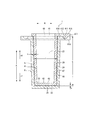
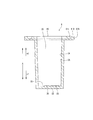
- Side sectional view showing a molding mold of the endoscope hood according to the first embodiment of the present invention Side sectional view showing a female mold of the same molding mold in particular.
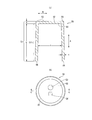
- a view showing a female mold of the same molding mold (a) is a plan view seen from the rear end surface side, and (b) is a partial cross-sectional view on the front end surface side.
- Side sectional view showing a male mold of the same molding mold A view showing a male mold of the same molding mold, (a) is a plan view seen from the front end surface side, and (b) is a bottom view seen from the rear end surface side.
- the figure which shows the hood for an endoscope obtained from the same mold (a) is a sectional view (b) is a plan view.
- FIG. 1 is a side sectional view of a molding die 1 (hereinafter, simply referred to as a molding die 1) of an endoscope hood.
- 2A and 2B are side sectional views of a particularly female mold of the molding mold 1
- FIG. 3A is a plan view of the female mold
- FIG. 3B is a partial cross-sectional view thereof.
- 4A and 4B are side sectional views of the male mold 1 in particular
- FIG. 5A is a bottom view of the male mold
- FIG. 5B is a plan view of the male mold.
- FIG. 6 is a cross-sectional view showing an endoscope hood obtained by the molding die 1.
- FIG. 1 is a side sectional view of a molding die 1 (hereinafter, simply referred to as a molding die 1) of an endoscope hood.
- 2A and 2B are side sectional views of a particularly female mold of the molding mold 1
- FIG. 3A is a plan view of the female mold
- FIG. 7 is a partial perspective view showing a state in which the endoscope hood is attached to the endoscope.
- FIG. 8 is a cross-sectional view and a plan view of the endoscope hood.
- FIG. 9 is a side sectional view of the molding die 2 (hereinafter, simply referred to as the molding die 2) of the endoscope hood, which is a partially modified example of the molding die 1.
- FIG. 10 is a cross-sectional view showing an endoscope hood obtained by the molding die 2.
- FIG. 11 is a partial perspective view showing a state in which the endoscope hood is attached to the endoscope.
- This molding mold 1 is a mold for forming an endoscope hood to be attached to the insertion side end (extending portion) of the endoscope. As shown in FIG. 7, the endoscope hood 50 is configured to be attached to the insertion side end (extending portion) 100E of the endoscope 100.
- the endoscope hood 50 is made of hydrogel.
- the hydrogel include a hydrogel formed by using only a hydrophilic monomer, a hydrogel formed by adding a hydrophobic monomer, a crosslinkable monomer, or both to a hydrophilic monomer, and the like.
- the hydrophilic monomer contributes to the water content of the hydrogel
- the hydrophobic monomer contributes to the action of adjusting the water content and swelling rate of the hydrogel, and the wettability of the obtained endoscopic hood 50 and the wettability of the obtained endoscopic hood 50. Affects flexibility.
- the crosslinkable monomer can control the density of the polymer chains of the hydrogel depending on the content thereof, and can impart mechanical strength, shape stability and solvent resistance to the hydrogel.
- the water content of the hydrogel is not particularly limited as long as it can be molded, but can be, for example, 20 to 70% by weight.
- Moisture content (% by weight) [(WD) / W] x 100 (W: moisture content, D: dry weight)
- the water content can be appropriately selected as needed.
- the water content of the exterior portion 51 and the water content of the disk portion 52 may be 20 to 70% by weight, respectively.
- the hydrophilic monomer preferably has one or more hydrophilic groups in the molecule, for example, 2-hydroxyethyl (meth) acrylate, 2-hydroxymethyl (meth) acrylate, hydroxypropyl (meth) acrylate, and glycerol (meth).
- hydrophilic monomers 2-hydroxyethyl (meth) acrylate, N, N-dimethyl (meth) acrylamide, and N-vinylpyrrolidone are preferably used in the present invention from the viewpoint of handleability.
- the blending ratio of the hydrophilic monomer is not particularly limited, but is preferably 50% by weight or more of the total polymerization components because it affects the water content of the obtained endoscopic hood 50.
- the compounding ratio of the hydrophilic monomer is less than 50% by weight, the endoscope hood 50 having a sufficient water content cannot be obtained, so that the antifouling property and the antifogging property of the endoscope hood 50 are lowered. It is not preferable because there is concern about it.
- hydrophobic monomer examples include siloxanyl (meth) acrylate, trifluoroethyl (meth) acrylate, methacrylamide, cyclohexyl (meth) acrylate, normal butyl (meth) acrylate, and the like, and among these, the hydrophobic monomer is selected. Two or more types may be used in combination.
- the hydrophobic monomer can change the water content of the obtained endoscopic hood 50 according to the blending amount. However, if the compounding ratio of the hydrophobic monomer is high, the water content is extremely lowered, and the flexibility of the obtained endoscopic hood 50 is lowered. Therefore, for example, it is less than 30% by weight based on the total amount of the monomers. Is preferable.
- crosslinkable monomer examples include ethylene glycol di (meth) acrylate, methylenebisacrylamide, 2-hydroxy-1,3-dimethacryloxypropane, trimethylolpropane triacrylate, and the like, and two or more of them are used. It may be used in combination.
- the blending amount of the crosslinkable monomer is preferably 0.1 to 10% by weight with respect to the total amount of the monomers from the viewpoint of the shape adjusting effect of the obtained endoscopic hood 50. If it is less than 0.1% by weight, the mesh structure of the endoscope hood 50 is insufficient, and if it exceeds 10% by weight, the mesh structure becomes excessive, and the endoscope hood 50 becomes brittle and flexible. The sex is reduced.
- polymerization initiator used when polymerizing the above-mentioned monomer mixture examples include peroxides such as lauroyl peroxide, cumene hydroperoxide, and benzoyl peroxide, which are general radical polymerization initiators, and azobisvaleronitrile. , Azobisisobutyronitrile and the like.
- the amount of the polymerization initiator added is preferably about 10 to 3500 ppm with respect to the total amount of the monomers.
- the endoscope hood 50 according to the present embodiment is formed into a desired shape after a single or a plurality of the above-mentioned monomers are mixed, and is formed of a single material.
- a monomer mixed solution obtained by mixing monomers as constituents is placed in a molding mold such as metal, glass, or plastic, sealed, and stepwise or continuously in a constant temperature bath or the like at 25 to 120 ° C. By raising the temperature in the range of 1 and completing the copolymerization reaction in 5 to 120 hours, a molding mold containing a polymer can be obtained.
- a molding mold containing a polymer can be obtained.
- ultraviolet rays, electron beams, gamma rays and the like can be used for polymerization.
- the molding die after completion of polymerization is cooled to room temperature, the polymer contained in the molding die is peeled off from the molding die, and if necessary, cut and polished, and then the polymer is hydrated and swollen. Hydrogel.
- the liquid (swelling liquid) to be used include, but are not limited to, water, physiological saline, an isotonic buffer solution, and a solution obtained by mixing an organic solvent such as ethanol with the liquid.
- the swelling liquid is heated to 60 to 100 ° C., and the polymer is immersed in the swelling liquid for a certain period of time to bring it into a swelling state.
- the obtained hydrogel can be stylized by subjecting it to high-pressure steam sterilization at 110 to 130 ° C. for 10 to 60 minutes in a state of being immersed in a swelling solution such as physiological saline.
- the endoscope hood 50 since it is excellent in antifogging and antifouling properties, body fluids and oils and fats adhering to the surface of the hydrogel covering the lens portion are contained during surgery and examination. It can be easily removed by the water ejected from the water supply mechanism provided in the endoscope 100. In addition, it becomes possible to suppress fogging. Therefore, even in a long-term operation or examination, it is not necessary to remove the endoscope 100 to remove contamination or fogging of the lens portion, so that the operation or examination can be shortened and the burden on the patient can be reduced. become.
- the endoscope hood 50 includes an exterior portion 51 and a disk portion 52.
- the endoscope hood 50 has an axial direction A and a radial direction R.
- the axial direction A of the endoscope hood 50 is along the insertion direction of the endoscope 100.
- the exterior portion 51 is formed in a circle in the direction perpendicular to the outer circumference of the disk portion 52.
- the exterior portion 51 may have a cylindrical shape extending in the axial direction A and a tapered shape extending in the insertion direction of the endoscope 100.
- the exterior portion 51 has a function of abutting on the endoscope 100 and fixing the endoscope hood 50 to the endoscope 100. Therefore, the inner diameter f of the exterior portion 51 is appropriately designed according to the endoscope 100 to be used.
- the endoscope hood 50 has a tip surface 55 located on the tip side of the endoscope hood 50 and a facing surface 56 facing the tip surface 55.
- the tip surface 55 is a surface on the tip side in the insertion direction of the endoscope 100 on which the endoscope hood 50 is mounted.
- the tip surface 55 includes an edge of the exterior portion 51 in the axial direction A and an outer surface of the disk portion 52.
- the facing surface 56 includes an edge of the exterior portion 51 in the axial direction A and an inner surface of the disk portion 52.
- the length b of the exterior portion 51 is not particularly limited as long as it is long enough to fix the endoscope hood 50 to the endoscope 100.
- the length b of the exterior portion 51 is preferably 5 to 20 mm, more preferably 10 to 15 mm. In this case, the length b of the exterior portion 51 is set to 20 mm.
- the thickness t of the exterior portion 51 is preferably 0.1 to 1.0 mm, more preferably 0.3 to 0.5 mm. In this case, the thickness t of the exterior portion 51 is 0.20 mm.
- the length b and the thickness t of the exterior portion 51 are appropriately designed.
- the disk portion 52 has a circular shape in a plan view.
- the disk portion 52 is located at the tip edge of the exterior portion 51 in the axial direction A, and is connected to the inner surface of the exterior portion 51.
- the disk portion 52 has a forceps port 53 that serves as an entrance / exit for forceps, and a water supply port 54 that serves as an outlet of a water supply unit for cleaning the disk portion 52.
- the forceps port 53 and the water supply port 54 are openings that penetrate the disk portion 52 and constitute the openings of the present invention.
- the thickness e of the disk portion 52 is preferably 0.01 to 1.0 mm, more preferably 0.05 to 0.7 mm, and most preferably 0.1 to 0.5 mm.
- the thickness e of the disk portion 52 exceeds 1.0 mm, it adversely affects the field of view obtained through the camera lens. Further, if the thickness e of the disk portion 52 is smaller than 0.01 mm, the strength of the disk portion 52 becomes low, and there is a concern that damage during use may occur, which is not preferable. In this case, the thickness e of the disk portion 52 is set to 0.2 mm.
- the thickness e of the disk portion 52, the position and shape of the forceps port 53, and the position and shape of the water supply port 54 are appropriately designed according to the structure of the endoscope to be mounted.
- the molding die 1 for molding the endoscope hood 50 configured in this way will be described in detail with reference to FIGS. 1 to 5.
- the molding die 1 includes a female die 6 and a male die 4.
- a material containing a hydrophilic monomer is filled in a predetermined filling space S formed between the female mold 6 and the male mold 4 when the male mold 4 is inserted from the insertion port 60 provided in the female mold, and the material is filled with the material.
- This is a mold for molding the hood 50 for an endoscope by subjecting the above to a copolymerization reaction.
- the molding die 1 may be formed of a material suitable for raising the temperature during the copolymerization reaction, and is formed of, for example, plastic.
- the molding die 1 has a cylindrical shape and has an axial direction A and a radial direction R. The axial direction A of the molding die 1 is along the axial direction A of the endoscope hood 50.
- the molding mold 1 of the present embodiment is composed of two members, a female mold 6 and a male mold 4.
- the filling space S is surrounded by an inner surface of the female mold 6 and an outer surface of the male mold 4.
- the shape of the female mold 6 and the shape of the male mold 4 can be adjusted according to the shape of the endoscope hood 50, respectively.
- adjust the shape of the endoscope hood 50 adjust the female type 6 and the male type 4, respectively, adjust only the male type 4 without adjusting the female type 6, or adjust the male type 4. Only the female mold 6 can be adjusted without it.
- the number of mold combination patterns can be increased, and the shape pattern of the endoscope hood 50 can be increased.
- the versatility of each type can be increased.
- the molding mold 1 either the edge of the insertion port 60 of the female mold 6 or the predetermined position corresponding to the insertion port 60 of the female mold 6 around the male mold 4 after being inserted into the female mold 6. It has a groove-shaped portion 61A that projects in the outer peripheral direction, and has a convex-shaped portion 41A that projects in the outer peripheral direction and can engage with the groove-shaped portion 61A, and is inserted into the female mold 6.
- the male mold 4 is positioned within the female mold 6 by engaging the groove-shaped portion 61A and the convex-shaped portion 41A.
- the female mold 6 has a bottomed cylindrical shape, and has a housing portion 23 for accommodating the male mold 4 at the center in the radial direction thereof.
- the accommodating portion 23 is a space surrounded by the inner surface 2A of the female mold 6, and the front end is closed in the axial direction A and the rear end is opened as an insertion port 60.
- the male mold 4 is configured to be inserted into the accommodating portion 23 from the insertion port 60 along the axial direction A.
- the female mold 6 has an insertion port 60 having an open rear end for inserting and removing the male mold 4, and an insertion port 60 and a tip surface 22 on the opposite side in the axial direction A.
- the first direction X1 for inserting the male mold 4 into the female mold 6 is the direction from the insertion port 60 at the rear end toward the tip surface 22, and the second direction X2 for removing the male mold 4 from the female mold 6 is the tip surface 22.
- the direction is from the rear end toward the insertion port 60.
- the tip surface 22 is located on the tip side in the insertion direction of the male mold 4 into the female mold 6.
- the first direction (insertion direction of the male mold 4 into the female mold 6) X1 is the insertion direction of the endoscope 100 to which the endoscope hood 50 molded by the molding mold 1 is mounted. Is consistent with.
- the inner surface 2A of the female mold 6 is an outer peripheral forming surface 24 corresponding to the outer peripheral surface of the endoscope hood 50.
- the inner surface 2A of the female mold 6 has a tapered shape that tapers toward the insertion direction of the endoscope 100 (first direction X1 in the present embodiment).
- the inclination angle of the inner surface 2A of the female mold 6 with respect to the axial direction A may be 0.01 degrees or more and 10.0 degrees or less, preferably 0.01 degrees or more and 5.0 degrees or less, more preferably. Is 0.01 degrees or more and 2.0 degrees or less.
- the outer peripheral forming surface 24 is provided on the entire inner surface 2A of the female mold 6.
- the outer peripheral forming surface 24 is a surface surrounding the filling space S.
- the outer peripheral forming surface 24 is arranged at a distance from the outer surface (mounting forming surface to be described later) of the male mold 4.
- the outer peripheral forming surface 24 is a surface corresponding to the outer peripheral surface of the exterior portion 51 of the endoscope hood 50.
- the inner surface of the tip surface 22 of the female mold 6 is the tip forming surface 33, which corresponds to the tip surface 55 of the endoscope hood 50.
- the tip forming surface 33 is a surface corresponding to the outer surface of the disk portion 52 of the endoscope hood 50.
- the tip forming surface 33 is arranged at the center of the female mold 6 in the radial direction R, and has a circular shape in a plan view.
- An opening forming portion 35 corresponding to an opening (forceps opening 53 and a water supply port 54) of the endoscope hood 50 is formed on the tip forming surface 33.
- the opening forming portion 35 projects in the axial direction A (second direction X2 of the present embodiment) from the tip forming surface 33.
- the opening forming portion 35 of the female mold 6 and the facing forming surface 43 of the male mold 4 come into contact with each other, and an opening penetrating the disk portion 52 of the endoscope hood 50 is formed.
- the tip forming surface 33 of the female mold 6 and the facing forming surface 43 of the male mold 4 are arranged apart from each other, and a thick disk portion 52 is formed.
- the position and shape of the opening of the endoscope hood 50 can be adjusted according to the position and shape of the opening forming portion 35.
- the opening forming portion 35 may be provided in the male mold 4, or may be provided in both the female mold 6 and the male mold 4.
- a groove-shaped portion 61A is provided on the entire edge portion (entire peripheral edge) of the rear end insertion port 60 of the female mold and projects in the outer peripheral direction.
- the groove-shaped portion 61A has a flange 610 formed in a circular shape on the edge of the insertion port 60 of the female mold 6 over the entire circumference, and one surface of the flange 610 facing the convex-shaped portion 41A described later.
- a groove 611 is formed in (a surface facing the second direction X2). In this case, the groove 611 is formed continuously in a circular shape over the entire circumference at substantially the center of one surface of the flange 610 in the radial direction.
- the groove 611 is formed in a substantially semicircular cross section or a substantially semicircular cross section.
- the dimension from the center of the insertion port 60 of the female mold 6 to the outer peripheral edge of the flange 610 is 10 mm, and the dimension from the center of the insertion port 60 of the female mold 6 to the deepest portion of the groove 611 of the flange 610 is 8 mm.
- the male type 4 is arranged in the axial direction A in the accommodating portion 23 of the female type 6.
- the male type 4 is located on the rear end insertion port 60 side of the female type 6, that is, the male rear end 41 forming the edge (entire peripheral edge) of the insertion port 60 and the male type 4 located on the front end surface side of the female type 4. It has a tip 42 and.
- the male tip 42 is configured with an opposed forming surface 43, which will be described later.
- the male type 4 has an outer surface surrounding the filling space S.
- the outer surface of the male mold 4 includes a facing forming surface 43 and a mounting forming surface 44.
- the facing forming surface 43 is a surface corresponding to the facing surface 56 of the endoscope hood 50.
- the facing forming surface 43 is a surface corresponding to the surface of the disk portion 52 on the mounting portion 511 side.
- the facing forming surface 43 is arranged at the center of the male mold 4 in the radial direction R, and has a circular shape in a plan view.
- the facing forming surface 43 of the male mold 4 is arranged at a distance from the tip forming surface 33 of the female mold 6 in the axial direction A.
- the distance e between the facing forming surface 43 and the tip forming surface 33 is the thickness e of the disk portion 52 of the endoscope hood 50.
- the thickness e of the disk portion 52 can be adjusted by adjusting the distance e between the facing forming surface 43 and the tip forming surface 33. Since the male mold 4 has the facing forming surface 43 and the female mold 6 has the tip forming surface 33, the tip surface of the endoscopic hood 50 can also be adjusted by adjusting one of the female mold 6 and the male mold 4. 55, the facing surface 56 and the region between them can be adjusted, and the versatility of the molding die 1 can be enhanced. As described above, the facing forming surface 43 abuts on the opening forming portion 35 of the female mold 6.
- the surface extending in the axial direction A from the facing forming surface 43 to the male rear end 41 constitutes the mounting forming surface 44.
- the distance b between the facing forming surface 43 and the male rear end 41 in the axial direction A is the length of the mounting forming surface 44 in the axial direction A, and is the length b of the mounting portion 511 of the endoscope hood 50.
- the mounting formation surface 44 is a surface corresponding to the inner peripheral surface of the mounting portion 511 of the endoscope hood 50.
- the mounting forming surface 44 is arranged so as to face the outer peripheral forming surface 24 of the female mold 6.
- the filling space S sandwiched between the outer peripheral forming surface 24 of the female mold 6 and the mounting forming surface 44 of the male mold 4 is a mounting space corresponding to the mounting portion 511 of the exterior portion 51 of the endoscope hood 50.
- the distance t between the outer peripheral forming surface 24 and the mounting forming surface 44 is the width of the mounting space, and is the thickness t of the mounting portion 511 of the endoscope hood 50.
- the thickness t of the mounting portion 511 can be adjusted by adjusting the distance t between the outer peripheral forming surface 24 and the mounting forming surface 44. Further, the inner diameter f of the mounting portion 511 can be adjusted by adjusting the outer diameter f of the mounting forming surface 44.
- the mounting formation surface 44 has a tapered shape that tapers toward the insertion direction of the endoscope 100 (first direction X1 in the present embodiment). In the configuration in which the mounting forming surface 44 extends in parallel with the outer peripheral forming surface 24, the thickness of the mounting portion 511 of the endoscope hood 50 is constant.
- the mounting forming surface 44 may not have a tapered shape and may be along the axial direction A, or may not be parallel to the outer peripheral forming surface 24.
- the distance between the outer peripheral forming surface 24 and the mounting forming surface 44 may change.
- the male mold 4 is provided with a convex shape portion 41A at a predetermined position corresponding to the insertion port 60 of the female mold 6 around the male mold 4 after being inserted into the female mold 6, and is projected in the outer peripheral direction.
- a convex shape portion 41A a plurality of plates 411 are formed at predetermined intervals in the circumferential direction at the edge of the male rear end 41 of the male mold 4, and each of these plates 411 faces the above-mentioned groove shape portion 61A.
- a convex portion 412 is formed on one of the surfaces to be formed.
- each convex portion 412 is formed in the convex shape portion 41A. It is formed in an arc shape in a plan view and a substantially semicircular cross section or a substantially semi-circular cross section so as to be fitted in the groove 611 of the groove-shaped portion 61A at substantially the center of one surface of each plate 411.
- the dimensions up to the groove 611 are the same.
- the male mold 4 is inserted after injecting a material containing a hydrophilic monomer into the female mold 6. Then, the material is copolymerized.
- the tip of the male mold 4 is inserted from the insertion port 60 at the rear end of the female mold 6, and the male mold 4 is inserted into the female mold 6, but the inner surface 2A of the female mold 6 and Since the outer surface 47 of the male mold 4 has a tapered shape that tapers toward the tip end side of the endoscope 100, the male mold 4 can be smoothly fitted into the female mold 6.
- each convex portion 412 having a substantially semicircular cross section of each plate 411 of the male die 4 is smoothly fitted to an arbitrary position of the circular groove 611 having a substantially semicircular cross section of the flange 610 at the rear end of the female die 6.
- the dimension from the center of the insertion port 60 of the female mold 6 to the groove 611 of the flange 610 is the convex portion 412 of each plate 411 from the center of the insertion port 60 of the male mold 4 inserted into the insertion port 60 of the female mold 6. Since the dimensions are the same as those up to, the male mold 4 is concentrically arranged in the female mold 6. Then, the disk portion 52 of the endoscope hood 50 is formed by the tip space sandwiched between the tip forming surface 33 of the female mold 6 and the facing forming surface 43 of the male mold 4, and the outer peripheral forming surface 24 of the female mold 6 is formed. The mounting portion 511 of the endoscope hood 50 is formed by the mounting space sandwiched between the mounting forming surface 44 of the male mold 4. By arranging the male molds 4 concentrically in the female mold 6 and stabilizing the position and angle of the male mold 4 in the female mold 6, the endoscope hood 50 has a constant thickness and the whole has predetermined dimensions and. Formed into a shape.
- the female mold 6 and the male mold 4 are provided, and the male mold 4 is inserted from the insertion port 60 provided in the female mold 6, and the female mold is inserted.
- a material containing a hydrophilic monomer is filled in a predetermined filling space generated between 6 and the male mold 4, and the endoscope hood is formed by a copolymerization reaction of this material, so that even when used for a long time. It is possible to mold an endoscope hood having excellent antifogging and antifouling properties, and it is possible to increase the versatility of the molding die.
- the female mold 6 has a groove-shaped portion 61A overhanging in the outer peripheral direction
- the male mold 4 has a convex-shaped portion 41A protruding in the outer peripheral direction
- the female mold has a female mold. Since the male mold 4 inserted in the 6 is positioned in the female mold 6 by engaging the groove-shaped portion 61A and the convex shape portion 41A, the male mold 4 is surely positioned in the female mold 6.
- the thickness of the hood for the endoscope can be made uniform, and the quality of the hood for the endoscope can be further improved.
- a flange 610 is formed over the entire circumference at the edge of the insertion port 60 of the female mold 6, and the groove 611 is formed on one surface of the flange 610 facing the convex-shaped portion 41A.
- a plurality of plates 411 are formed and provided at predetermined positions around the male mold 4 at predetermined intervals in the circumferential direction, and the convex shape portion 41A faces the groove shape portion 61A of each plate 411. Since the convex portion 412 is formed and provided on one of the surfaces, the structure is simple and the manufacturing cost can be suppressed to a low level.
- the groove-shaped portion 61A and the convex-shaped portion 41A can be variously changed as follows. (1) In the above embodiment, the groove-shaped portion 61A projects outward from the edge of the insertion port 60 of the female mold 6, and the convex-shaped portion 41A of the male mold 4 after being inserted into the female mold 6. It was assumed that the groove-shaped portion 61A and the convex-shaped portion 41A were engaged with each other by projecting in the outer peripheral direction at a predetermined position corresponding to the insertion port 60 of the female mold 6 in the periphery, but the groove-shaped portion was formed.
- the groove-shaped portion 61A has a flange 610 formed on the edge of the insertion port 60 of the female mold 6 over the entire circumference and faces the convex-shaped portion 41A of the flange 610.
- Grooves 611 are formed on one of the surfaces, and a plurality of convex shaped portions 41A are formed at predetermined positions around the male mold 4 at predetermined intervals (120 ° intervals in this case) in the circumferential direction (three in this case). ) Is formed, and a convex portion 412 is formed on one surface of each plate 411 facing the groove-shaped portion 61A. On the contrary, the groove-shaped portion is formed. , A flange is formed at a predetermined position around the male mold over the entire circumference, a groove is formed on one surface facing the convex shape portion of the flange, and the convex shape portion is inserted into the female mold.
- a plurality of plates may be formed on the edge of the mouth at predetermined intervals in the circumferential direction, and a convex portion may be formed on one surface of each plate facing the groove-shaped portion. Even in this way, the same effects as those of the above embodiment can be obtained.
- the groove 611 is continuously formed on one surface of the flange 610 in a circular shape over the entire circumference, and each convex portion 412 is formed on one surface of each plate 411 in an arc shape.
- the grooves are formed on one surface of the flange in a partially arcuate or dot-like discontinuity in the circumferential direction, and each convex portion is formed on one surface of each plate in an arcuate shape or a dot.
- the groove-shaped portion 61A has a flange 610 formed on the edge of the insertion port 60 of the female mold 6 over the entire circumference and faces the convex-shaped portion 41A of the flange 610.
- Grooves 611 are formed on one of the surfaces, and a plurality of convex shaped portions 41A are formed at predetermined positions around the male mold 4 at predetermined intervals (120 ° intervals in this case) in the circumferential direction (three in this case).
- the groove-shaped portion is formed.
- a plurality of (for example, three) plates are formed at predetermined positions at predetermined positions around the edge of the female insertion slot or around the male mold at predetermined intervals (for example, 120 ° intervals) in the circumferential direction.
- a groove is formed on one surface facing the convex shape portion, and the convex shape portion is formed with a flange at a predetermined position around the male mold or at the edge of the insertion port of the female mold over the entire circumference.
- a convex portion may be formed on one surface of the flange facing the groove-shaped portion.
- the grooves may be formed in an arc shape or a dot shape on one surface of the plate, and the convex portion may be continuously formed in a circle on one surface of the flange over the entire circumference or partially in the circumferential direction. It may be formed discontinuously in an arc shape or a dot shape. Even in this way, the same effects as those of the above embodiment can be obtained.
- both the groove-shaped portion and the convex-shaped portion are composed of a flange or a plurality of plates, the groove-shaped portion has a groove formed on one surface thereof, and the convex-shaped portion has a groove formed on one surface thereof. A convex portion may be formed. Even in this way, the same effects as those of the above embodiment can be obtained.
- the molding mold 1 of the endoscope hood 50 of the type in which the exterior portion 51 has no extending portion extending from the mounting portion 511 to the tip side in the insertion direction of the endoscope has been illustrated.
- the molding mold 1 of the endoscope hood 50 of the type having the extension portion 512 extending from the mounting portion 511 to the tip side in the insertion direction of the endoscope on the exterior portion 51 as shown in FIG. 10 is also female.
- a groove shape that projects outwardly to either the edge of the insertion port 60 of the mold 6 or a predetermined position corresponding to the insertion port 60 of the female mold 6 around the male mold 4 after being inserted into the female mold 6.
- the tip surface 22 of the female die 6 is formed to be thick and extends on the extension of the outer peripheral forming surface 24 at the outermost peripheral portion of the tip forming surface 33. It differs from the molding die 1 in the above embodiment in that a groove 340 having a predetermined depth is formed as the protruding portion forming portion 34A.
- the outer peripheral forming surface 24 of the female mold 6 and the mounting forming surface 44 of the male mold 4 may each have a tapered shape or a cylindrical shape as in the above embodiment.
- the male mold 4 is inserted after injecting a material containing a hydrophilic monomer into the female mold 6 in the same manner as in the above embodiment, and the material is used. Copolymerize.
- FIG. 9 (1) after injecting the material into the female mold 6, the tip of the male mold 4 is inserted from the insertion port 60 at the rear end of the female mold 6, and the male mold 4 is inserted into the female mold 6.
- FIG. 9 (2) the groove-shaped portion 61A at the rear end of the female mold 6 and the convex-shaped portion 41A at the rear end of the male mold 4 are engaged with the fitting of the male mold 4 into the female mold 6.
- each convex portion 412 having a substantially semicircular cross section of each plate 411 of the male die 4 is smoothly fitted to an arbitrary position of the circular groove 611 having a substantially semicircular cross section of the flange 610 at the rear end of the female die 6.
- the dimension from the center of the insertion port 60 of the female mold 6 to the groove 611 of the flange 610 is the convex portion 412 of each plate 411 from the center of the insertion port 60 of the male mold 4 inserted into the insertion port 60 of the female mold 6. Since the dimensions are the same as those up to, the male mold 4 is concentrically arranged in the female mold 6.
- the disk portion of the endoscope hood 50 is formed by the tip space sandwiched between the tip forming surface 33 of the female mold 6 and the facing forming surface 43 of the male mold 4. 52 is formed, and the mounting portion 511 of the endoscope hood 50 is formed by the mounting space sandwiched between the outer peripheral forming surface 24 of the female mold 6 and the mounting forming surface 44 of the male mold 4, and the tip of the female mold 6 is formed.
- the extension portion forming portion 34A forming the groove 340 of the outermost outermost portion of the surface 33, that is, extending on the tip side extension of the mounting space between the outer peripheral forming surface 24 of the female mold 6 and the mounting forming surface 44 of the male mold 4.
- a protrusion 512 is formed.
- the hood 50 for the endoscope is formed by arranging the male molds 4 concentrically in the female mold 6 and stabilizing the position and angle of the male mold 4 in the female mold 6. The thickness is constant and the whole is formed to a predetermined size and shape.
Landscapes
- Health & Medical Sciences (AREA)
- Life Sciences & Earth Sciences (AREA)
- Surgery (AREA)
- Engineering & Computer Science (AREA)
- Biomedical Technology (AREA)
- Molecular Biology (AREA)
- Pathology (AREA)
- Radiology & Medical Imaging (AREA)
- Nuclear Medicine, Radiotherapy & Molecular Imaging (AREA)
- Biophysics (AREA)
- Physics & Mathematics (AREA)
- Heart & Thoracic Surgery (AREA)
- Medical Informatics (AREA)
- Optics & Photonics (AREA)
- Animal Behavior & Ethology (AREA)
- General Health & Medical Sciences (AREA)
- Public Health (AREA)
- Veterinary Medicine (AREA)
- Manufacturing & Machinery (AREA)
- Endoscopes (AREA)
- Instruments For Viewing The Inside Of Hollow Bodies (AREA)
Abstract
内視鏡フードの厚さを均一にして品質をより高めた成形型を提供する。内視鏡用フードの成形型1は雌型6及び雄型4を備え、雌型6に外周方向に張り出される溝形形状部61Aを有し、雄型4に外周方向に張り出される凸形形状部41Aを有し、雌型6内に挿入される雄型4を、溝形形状部61Aと凸形形状部41Aとの係合により、雌型6内で位置決めするようにした。
Description
本発明は、内視鏡に装着する内視鏡用フードを成型するための成形型に関する。
内視鏡を用いた手術や検査においては、内視鏡の延出部(挿入側端部)から生体組織までの至適距離の確認及び視野の確保を目的として、内視鏡の延出部に透明なフードが装着される。ここで、かかるフードは、ABS、ポリカーボネート、塩化ビニル、シリコーンゴム等により形成されている。
しかしながら、かかるフードは、内視鏡の延出部から生体組織までの至適距離の確認及び視野の確保を目的として装着されるものであり、カメラレンズや照明レンズの部分は、被覆されていないため、フードを装着した内視鏡を用いた検査や手術において、体液や油脂が付着し、視界が不鮮明になるという課題を有していた。
このような課題を解決するために、親水性モノマーを用いて形成されたハイドロゲルによって内視鏡用フードを形成することが考えられる。ハイドロゲルによって内視鏡用フードを形成する方法としては、親水性モノマーを含む材料をプラスチック等の成形型に充填し、昇温することで共重合反応させる。次いで、共重合反応した材料を水和膨潤させることによってハイドロゲルからなる内視鏡用フードを得ることができる。当該方法によって得られる内視鏡用フードの形状は、親水性モノマーを含む材料を充填する成形型の形状に対応する。しかし、内視鏡は、同一の形状のものだけでなく、様々な形状のものが提供されている。そのため、内視鏡の形状に応じて異なる成形型を用いて製造する必要がある。
また、特許文献1に示すように、内視鏡用フードとして、筒形状の外装部と、外装部の内側面に連なる円盤部と、を有するものが提供されている。このような内視鏡用フードでは、内視鏡のカメラレンズ等の位置によって円盤部の形状を異ならせ、内視鏡の先端の径によって外装部の内径を異ならせる。すなわち、円盤部及び外装部のそれぞれで調整が必要であり、成形型の汎用性を高めることができなかった。
そこで、本発明は、上述した課題を解決するためになされたものであり、防曇性や防汚性に優れた内視鏡用フードを成形でき、かつ成形型の汎用性を高めることができ、さらに内視鏡フードの厚さを均一にして品質をより高めることのできる内視鏡用フードの成形型を提供することを目的とする。
上記目的を達成するために、本発明は、雌型及び雄型を備え、前記雌型に設けられる挿入口から前記雄型が挿入されて、前記雌型と前記雄型の間に生じる所定の充填空間に親水性モノマーを含む材料が充填され、当該材料の共重合反応によって内視鏡用フードを成形する内視鏡用フードの成形型であって、前記雌型の挿入口の縁部又は前記雌型に挿入後の前記雄型の周囲で前記雌型の挿入口に対応する所定の位置のいずれか一方に外周方向に張り出される溝形形状部を有し、他方に外周方向に張り出されて前記溝形形状部に係合可能な凸形形状部を有し、前記雌型内に挿入される前記雄型を、前記溝形形状部と前記凸形形状部との係合により、前記雌型内で位置決めする、ことを要旨とする。
また、この内視鏡用フードの成形型は次のように具体化される。
(1)溝形形状部は、雌型の挿入口の縁部又は雄型の周囲で所定の位置に全周に亘ってフランジが形成され、前記フランジの凸形形状部に対向される一方の面に溝が形成されてなる。この場合、溝はフランジの一方の面に全周に亘って円形に連続して又は周方向に部分的に円弧状若しくは点状に不連続にして形成されることが好ましい。
(2)上記(1)に代えて、溝形形状部は、雌型の挿入口の縁部又は雄型の周囲で所定の位置に周方向に所定の間隔で複数のプレートが形成され、前記各プレートの凸形形状部に対向される一方の面に溝が形成されてなるものとしてもよい。この場合、溝はプレートの一方の面に円弧状若しくは点状に形成されることが好ましい。
(3)凸形形状部は、雄型の周囲で所定の位置又は雌型の挿入口の縁部に周方向に所定の間隔で複数のプレートが形成され、前記各プレートの溝形形状部に対向される一方の面に凸状部が形成されてなる。この場合、凸状部はプレートの一方の面に円弧状若しくは点状に形成されることが好ましい。
(4)上記(3)に代えて、凸形形状部は、雄型の周囲で所定の位置又は雌型の挿入口の縁部に全周に亘ってフランジが形成され、前記フランジの溝形形状部に対向される一方の面に凸状部が形成されてなるものとしてもよい。この場合、凸状部はフランジの一方の面に全周に亘って円形に連続して又は周方向に部分的に円弧状若しくは点状に不連続にして形成されることが好ましい。
上記(1)-(4)は選択的に組み合わせられる。
また、この内視鏡用フードの成形型は次のように具体化される。
(1)溝形形状部は、雌型の挿入口の縁部又は雄型の周囲で所定の位置に全周に亘ってフランジが形成され、前記フランジの凸形形状部に対向される一方の面に溝が形成されてなる。この場合、溝はフランジの一方の面に全周に亘って円形に連続して又は周方向に部分的に円弧状若しくは点状に不連続にして形成されることが好ましい。
(2)上記(1)に代えて、溝形形状部は、雌型の挿入口の縁部又は雄型の周囲で所定の位置に周方向に所定の間隔で複数のプレートが形成され、前記各プレートの凸形形状部に対向される一方の面に溝が形成されてなるものとしてもよい。この場合、溝はプレートの一方の面に円弧状若しくは点状に形成されることが好ましい。
(3)凸形形状部は、雄型の周囲で所定の位置又は雌型の挿入口の縁部に周方向に所定の間隔で複数のプレートが形成され、前記各プレートの溝形形状部に対向される一方の面に凸状部が形成されてなる。この場合、凸状部はプレートの一方の面に円弧状若しくは点状に形成されることが好ましい。
(4)上記(3)に代えて、凸形形状部は、雄型の周囲で所定の位置又は雌型の挿入口の縁部に全周に亘ってフランジが形成され、前記フランジの溝形形状部に対向される一方の面に凸状部が形成されてなるものとしてもよい。この場合、凸状部はフランジの一方の面に全周に亘って円形に連続して又は周方向に部分的に円弧状若しくは点状に不連続にして形成されることが好ましい。
上記(1)-(4)は選択的に組み合わせられる。
本発明の内視鏡用フードの成形型によれば、雌型及び雄型を備え、雌型に設けられる挿入口から雄型が挿入されて、雌型と雄型の間に生じる所定の充填空間に親水性モノマーを含む材料が充填され、当該材料の共重合反応によって内視鏡用フードを成形するものとしたので、長時間の使用においても防曇性や防汚性に優れた内視鏡用フードを成形でき、かつ成形型の汎用性を高めることができ、また、この成形型では、特に、雌型又は雄型のいずれか一方に外周方向に張り出される溝形形状部を有し、他方に外周方向に張り出される凸形形状部を有し、雌型内に挿入される雄型を、溝形形状部と凸形形状部との係合により、雌型内で位置決めするようにしたので、雌型内で雄型を確実に位置決めすることができ、内視鏡用フードの厚みを均一にして内視鏡用フードの品質をより高めることができる、という本発明独自の格別な効果を奏する。
以下、適宜図面を参照しながら、実施の形態を詳細に説明する。但し、必要以上に詳細な説明は省略する場合がある。例えば、既によく知られた事項の詳細説明や実質的に同一の構成に対する重複説明を省略する場合がある。これは、以下の説明が不必要に冗長になるのを避け、当業者の理解を容易にするためである。なお、発明者は、当業者が本開示を十分に理解するために添付図面及び以下の説明を提供するのであって、これらによって特許請求の範囲に記載の主題を限定することを意図するものではない。
なお、以下の図面の記載において、同一又は類似の部分には、同一又は類似の符号を付している。ただし、図面は模式的なものであり、各寸法の比率等は現実のものとは異なる場合があることに留意すべきである。したがって、具体的な寸法等は、以下の説明を参酌して判断すべきである。また、図面相互間においても互いの寸法の関係や比率が異なる部分が含まれる場合がある。
図1、及び図2乃至図5を参照して、一実施の形態に係る内視鏡用フードの成形型1について説明する。図1は内視鏡用フードの成形型1(以下、単に成形型1という。)の側面断面図である。図2はこの成形型1の特に雌型の側面断面図で、図3(a)は同雌型の平面図、図3(b)はその部分断面図である。図4はこの成形型1の特に雄型の側面断面図で、図5(a)は同雄型の底面図、図5(b)は同雄型の平面図である。図6はこの成形型1によって得られる内視鏡用フードを示す断面図である。図7は同内視鏡用フードが内視鏡に装着された状態を示す部分斜視図である。図8は同内視鏡用フードの断面図及び平面図である。図9は成形型1の一部変更例である内視鏡用フードの成形型2(以下、単に成形型2という。)の側面断面図である。図10はこの成形型2によって得られる内視鏡用フードを示す断面図である。図11は同内視鏡用フードが内視鏡に装着された状態を示す部分斜視図である。
この成形型1は、内視鏡の挿入側端部(延出部)に装着される内視鏡用フードを形成するための型である。図7に示すように、内視鏡用フード50は、内視鏡100の挿入側端部(延出部)100Eに装着されるように構成されている。
本実施の形態では、内視鏡用フード50はハイドロゲル製である。ハイドロゲルとしては、親水性モノマーのみを用いて形成されたハイドロゲルや、親水性モノマーに疎水性モノマー若しくは架橋性モノマー又はその両方を添加して形成されたハイドロゲル等が挙げられる。親水性モノマーは、ハイドロゲルの含水率に対して寄与し、疎水性モノマーは、ハイドロゲルの含水率や膨潤率の調整作用に対して寄与し、得られる内視鏡用フード50の濡れ性や柔軟性に対して影響を与える。また、架橋性モノマーは、その含有量によって、ハイドロゲルの高分子鎖の密度を制御することが可能となり、ハイドロゲルに機械的強度や形状安定性や耐溶剤性を付与することができる。
ハイドロゲルの含水率は、成形可能であれば特に限定されないが、例えば、20~70重量%とすることができる。
含水率(重量%)=〔(W-D)/W〕×100(W:含水重量、D:乾燥重量)
また、必要に応じて、含水率を適宜選択することができる。例えば、外装部51の含水率及び円盤部52の含水率は、それぞれ20~70重量%であってもよい。
含水率(重量%)=〔(W-D)/W〕×100(W:含水重量、D:乾燥重量)
また、必要に応じて、含水率を適宜選択することができる。例えば、外装部51の含水率及び円盤部52の含水率は、それぞれ20~70重量%であってもよい。
親水性モノマーとしては、1以上の親水基を分子内に有するものが好ましく、例えば、2-ヒドロキシエチル(メタ)アクリレート、2-ヒドロキシメチル(メタ)アクリレート、ヒドロキシプロピル(メタ)アクリレート、グリセロール(メタ)アクリレート、アクリルアミド、N,N-ジメチル(メタ)アクリルアミド、N,N-ジエチル(メタ)アクリルアミド、N-ビニルピロリドン、ダイアセトンアクリルアミド、N-ビニルアセトアミド、(メタ)アクリル酸、(メタ)アクリルオキシエチルコハク酸、イタコン酸、メタクリルアミドプロピルトリアンモニウムクロライド、2,3-ジヒドロキシプロピル(メタ)アクリレート等が挙げられ、これらの中から親水性モノマーを2種以上組み合わせて用いてもよい。
上述の親水性モノマーの中でも、2-ヒドロキシエチル(メタ)アクリレート、N,N-ジメチル(メタ)アクリルアミド、N-ビニルピロリドンが、取扱い性の観点から、本願発明においては好ましく用いられる。
親水性モノマーの配合率は、特に限定されないが、得られる内視鏡用フード50の含水率に影響を及ぼすことから、全重合成分中の50重量%以上であることが好ましい。親水性モノマーの配合率が50重量%未満の場合、十分な含水率を有する内視鏡用フード50が得られないことから、内視鏡用フード50の防汚性や防曇性が低下することが懸念されるため好ましくない。
疎水性モノマーとしては、例えば、シロキサニル(メタ)アクリレート、トリフルオロエチル(メタ)アクリレート、メタクリルアミド、シクロヘキシル(メタ)アクリレート、ノルマルブチル(メタ)アクリレート等が挙げられ、これらの中から疎水性モノマーを2種以上組み合わせて用いてもよい。
疎水性モノマーは、配合量に応じて得られる内視鏡用フード50の含水性を変化させることができる。ところが、疎水性モノマーの配合率が高いと含水性が極端に低下し、得られる内視鏡用フード50の柔軟性が低下することから、例えば、モノマー総量に対して30重量%未満であることが好ましい。
架橋性モノマーとしては、例えば、エチレングリコールジ(メタ)アクリレート、メチレンビスアクリルアミド、2-ヒドロキシ-1,3-ジメタクリロキシプロパン、トリメチロールプロパントリアクリレート等が挙げられ、これらの中から2種以上組み合わせて用いてもよい。
架橋性モノマーの配合量は、得られる内視鏡用フード50の形状調節効果の観点から、モノマー総量に対して0.1~10重量%が好ましい。0.1重量%未満の場合は、内視鏡用フード50の網目構造が不足し、10重量%を超えると逆に網目構造が過剰となり、内視鏡用フード50が脆くなり、かつ、柔軟性が低下する。
上述のモノマーの混合物を重合させる際に使用する重合開始剤としては、一般的なラジカル重合開始剤であるラウロイルパーオキサイド、クメンハイドロパーオキサイド、ベンゾイルパーオキサイド等の過酸化物や、アゾビスバレロニトリル、アゾビスイソブチロニトリル等が挙げられる。重合開始剤の添加量は、モノマー総量に対して10~3500ppm程度が好ましい。
本実施の形態に係る内視鏡用フード50は、上述のモノマーを単一で或いは複数を混合した後、所望の形状に形成するものであり、単一の材料において形成される。
ポリマーを得る工程として、構成成分であるモノマーを混合して得られるモノマー混合液を金属やガラスやプラスチック等の成形型に入れて密閉し、恒温槽等で段階的又は連続的に25~120℃の範囲で昇温し、5~120時間で共重合反応を完了させることによりポリマーを含む成形型を得ることができる。重合に関しては、紫外線や電子線やガンマ線等を用いることが可能である。
ハイドロゲルを得る工程として、重合終了後の成形型を室温に冷却し、成形型に入っているポリマーを成形型から剥離し、必要に応じて、切削、研磨した後に、ポリマーを水和膨潤させてハイドロゲルとする。使用する液体(膨潤液)としては、例えば、水、生理食塩水、等張性緩衝液及びこれらにエタノール等の有機溶媒を混合した溶液等が挙げられるがこれらに限定されない。膨潤液を60~100℃に加温し、ポリマーを一定時間膨潤液に浸漬させて膨潤状態とする。また、膨潤処理時にポリマーに付着する未反応のモノマーを除去することが好ましい。得られたハイドロゲルは、生理食塩水等の膨潤液に浸漬した状態で、110~130℃、10~60分間の高圧蒸気滅菌に供することにより定形化することができる。
本実施の形態に係る内視鏡用フード50によれば、防曇性や防汚性に優れることから、手術や検査時において、レンズ部分を被覆するハイドロゲル表面に付着した体液や油脂を内視鏡100に供えた送水機構から噴出される水により容易に除去することが可能である。加えて、曇りも抑止することが可能になる。そのため、長時間に渡る手術や検査においても、レンズ部の汚染や曇りを除去するための内視鏡100の抜き取りが不要なことから、手術や検査の短時間化や、患者の負担軽減が可能になる。
図7及び図8に示すように、内視鏡用フード50は、外装部51と、円盤部52と、を備える。内視鏡用フード50は、軸方向Aと、径方向Rと、を有する。内視鏡用フード50の軸方向Aは、内視鏡100の挿入方向に沿っている。外装部51は、円盤部52の外周より垂直方向に円設する。外装部51は、軸方向Aに延びる円筒形状であり、内視鏡100の挿入方向に向かって細くなるテーパー形状であってよい。外装部51は、内視鏡100に当接し、内視鏡用フード50を内視鏡100に固定する機能を有する。よって、外装部51の内径fは、使用する内視鏡100に合わせ適宜設計される。
図8に示すように、内視鏡用フード50は、内視鏡用フード50の先端側に位置する先端面55と、先端面55と対向する対向面56と、を有する。先端面55は、内視鏡用フード50が装着される内視鏡100の挿入方向における先端側の面である。先端面55は、外装部51の軸方向Aの端縁と、円盤部52の外側の面と、を含む。対向面56は、外装部51の軸方向Aの端縁と、円盤部52の内側の面と、を含む。
外装部51の長さbは、内視鏡用フード50を内視鏡100に固定するのに十分な長さであれば特に限定されない。外装部51の長さbは、5~20mmが好ましく、10~15mmがより好ましい。この場合、外装部51の長さbは20mmとしてある。また、外装部51の厚みtは、0.1~1.0mmが好ましく、0.3~0.5mmがより好ましい。この場合、外装部51の厚みtは0.20mmとしてある。外装部51の長さb及び厚みtは、適宜設計される。
円盤部52は、平面視にて円形状である。円盤部52は、外装部51の軸方向Aにおける先端縁に位置し、外装部51の内面に連なっている。円盤部52は、鉗子の出入り口となる鉗子口53と、円盤部52を洗浄するための送水部の出口となる送水口54と、を有する。鉗子口53及び送水口54は、円盤部52を貫通した開口であり、本発明の開口を構成する。円盤部52の厚みeは、0.01~1.0mmが好ましく、0.05~0.7mmがより好ましく、0.1~0.5mmが最も好ましい。円盤部52の厚みeは、1.0mmを超過すると、カメラレンズを介して得られる視野に悪影響を及ぼす。また、円盤部52の厚みeは、0.01mmよりも小さい場合、円盤部52の強度が低くなり、使用時の破損が生じることが懸念されるため好ましくない。この場合、円盤部52の厚みeは0.2mmとしてある。円盤部52の厚みe、鉗子口53の位置及び形状、送水口54の位置及び形状は、装着する内視鏡の構造に応じて、適宜設計される。
次いで、このように構成された内視鏡用フード50を成形する成形型1について、図1から図5を参照して詳細に説明する。図1に示すように、成形型1は、雌型6と、雄型4と、を備える。成形型1は、雌型に設けられる挿入口60から雄型4が挿入されて雌型6と雄型4の間に生じる所定の充填空間Sに親水性モノマーを含む材料を充填させ、当該材料を共重合反応させることによって内視鏡用フード50を成形するための型である。成形型1は、共重合反応させる際の昇温に適切な材料によって形成されていればよく、例えば、プラスチックによって形成されている。成形型1は、円柱形状であり、軸方向Aと径方向Rを有する。成形型1の軸方向Aは、内視鏡用フード50の軸方向Aに沿っている。
雌型6、雄型4はいずれも一つのピースからなる。よって、本実施の形態の成形型1は、雌型6と、雄型4と、の2つの部材によって構成されている。充填空間Sは、雌型6の内面と、雄型4の外面と、によって囲まれている。
成形型1が2つの型(雌型6及び雄型4)を有するため、内視鏡用フード50の形状に応じて雌型6の形状と雄型4の形状をそれぞれ調整することができる。内視鏡用フード50の形状を調整する際に、雌型6及び雄型4をそれぞれ調整したり、雌型6を調整せずに雄型4のみを調整したり、雄型4を調整せずに雌型6のみを調整したりすることができる。型の組み合わせパターンが増え、内視鏡用フード50の形状パターンを増やすことができる。それぞれの型の汎用性を高めることができる。
また、この成形型1では、雌型6の挿入口60の縁部又は雌型6に挿入後の雄型4の周囲で雌型6の挿入口60に対応する所定の位置のいずれか一方に外周方向に張り出される溝形形状部61Aを有し、他方に外周方向に張り出されて溝形形状部61Aに係合可能な凸形形状部41Aを有し、雌型6内に挿入される雄型4を、溝形形状部61Aと凸形形状部41Aとの係合により、雌型6内で位置決めするようになっている。
図2及び図3に示すように、雌型6は、有底の円筒形状であり、その径方向の中心に雄型4を収容する収容部23を有する。収容部23は、雌型6の内面2Aによって囲まれた空間であり、軸方向Aにおいて先端は閉塞され、後端は挿入口60として開口されている。雄型4が、挿入口60から軸方向Aに沿って収容部23内に挿入されるように構成されている。このようにして雌型6は、雄型4を出し入れする後端を開口された挿入口60と、この挿入口60と軸方向Aにおける反対側の先端面22と、を有する。
雄型4を雌型6へ挿入する第1方向X1は、後端の挿入口60から先端面22に向かう方向であり、雄型4を雌型6から取り出す第2方向X2は、先端面22から後端の挿入口60に向かう方向である。先端面22は、雄型4の雌型6への挿入方向の先端側に位置する。本実施の形態では、第1方向(雄型4の雌型6への挿入方向)X1は、当該成形型1によって成形される内視鏡用フード50が装着される内視鏡100の挿入方向と一致している。
雌型6の内面2Aは、内視鏡用フード50の外周面に対応する外周形成面24になっている。雌型6の内面2Aは、内視鏡100の挿入方向(本実施の形態における第1方向X1)に向かって細くなるテーパー形状である。なお、雌型6の内面2Aの軸方向Aに対する傾斜角度は、0.01度以上10.0度以下であってよく、好ましくは、0.01度以上5.0度以下であり、より好ましくは、0.01度以上2.0度以下である。外周形成面24は、雌型6の内面2A全体に設けられている。外周形成面24は、充填空間Sを囲む面である。外周形成面24は、雄型4の外面(後述する装着形成面)と間隔を空けて配置されている。外周形成面24は、内視鏡用フード50の外装部51の外周面に対応する面である。
この雌型6の先端面22の内面は先端形成面33で、内視鏡用フード50の先端面55に対応する面である。先端形成面33は、内視鏡用フード50の円盤部52の外側の面に対応する面である。先端形成面33は、雌型6の径方向Rの中央に配置され、平面視にて円形状である。
この先端形成面33には、内視鏡用フード50の開口(鉗子口53及び送水口54)に対応する開口形成部35が形成されている。開口形成部35は、先端形成面33から軸方向A(本実施の形態の第2方向X2)に突出している。開口形成部35が設けられている領域では、雌型6の開口形成部35と雄型4の対向形成面43が当接し、内視鏡用フード50の円盤部52を貫通する開口が形成される。開口形成部35の周囲の領域では、雌型6の先端形成面33と雄型4の対向形成面43が離間して配置され、厚みを有する円盤部52が形成される。
開口形成部35の位置及び形状によって、内視鏡用フード50の開口の位置及び形状を調整することができる。また、他の形態として、開口形成部35は、雄型4に設けられてもよいし、雌型6及び雄型4の両方に設けられてもよい。なお、開口形成部35を雌型6及び雄型4のいずれか一方に設けることにより、内視鏡用フード50の開口パターンを調整する際に、雌型6及び雄型4の一方のみを調整すればよく、成形型1の汎用性を高めることができる。
また、この雌型の後端挿入口60の縁部全体(全周縁)には、溝形形状部61Aが設けられて外周方向に張り出されている。この溝形形状部61Aは、雌型6の挿入口60の縁部に全周に亘って円形にフランジ610が形成され、フランジ610の、後述する凸形形状部41Aに対向される一方の面(第2方向X2に向けられる面)に溝611が形成されてなる。この場合、溝611はフランジ610の一方の面の径方向略中央に全周に亘って円形に連続して形成される。また、この場合、溝611は断面略半円状若しくは断面略かまぼこ形状に形成される。なお、雌型6の挿入口60の中心からフランジ610の外周縁までの寸法は10mmであり、雌型6の挿入口60の中心からフランジ610の溝611最深部までの寸法は8mmである。
図4及び図5に示すように、雄型4は、雌型6の収容部23内において軸方向Aに配置されている。雄型4は、雌型6の後端挿入口60側に位置する、つまり挿入口60の縁部(全周縁部)をなす雄後端41と、雌型4の先端面側に位置する雄先端42と、を有する。雄先端42に後述する対向形成面43が構成される。
雄型4は、充填空間Sを囲む外面を有する。雄型4の外面は、対向形成面43と、装着形成面44とを含む。対向形成面43は、内視鏡用フード50の対向面56に対応する面である。対向形成面43は、円盤部52の装着部511側の面に対応する面である。対向形成面43は、雄型4の径方向Rにおける中央に配置され、平面視にて円形状である。
雄型4の対向形成面43は、雌型6の先端形成面33と軸方向Aにおいて間隔を空けて配置されている。対向形成面43と先端形成面33の間隔eは、内視鏡用フード50の円盤部52の厚みeとなる。対向形成面43と先端形成面33の間隔eを調整することによって、円盤部52の厚みeを調整できる。雄型4が対向形成面43を有し、雌型6が先端形成面33を有することにより、雌型6及び雄型4の一方を調整することによっても、内視鏡用フード50の先端面55、対向面56及びその間の領域を調整でき、成形型1の汎用性を高めることができる。対向形成面43は、上述のように、雌型6の開口形成部35に当接する。
対向形成面43から雄後端41まで軸方向Aに延びる面は、装着形成面44を構成する。対向形成面43と雄後端41の軸方向Aの間隔bは、装着形成面44の軸方向Aの長さであり、内視鏡用フード50の装着部511の長さbとなる。
装着形成面44は、内視鏡用フード50の装着部511の内周面に対応する面である。装着形成面44は、雌型6の外周形成面24と対向して配置されている。雌型6の外周形成面24と雄型4の装着形成面44とによって挟まれた充填空間Sは、内視鏡用フード50の外装部51の装着部511に対応する装着空間である。外周形成面24と装着形成面44の間隔tは、装着空間の幅であり、内視鏡用フード50の装着部511の厚みtとなる。外周形成面24と装着形成面44の間隔tを調整することによって、装着部511の厚みtを調整できる。また、装着形成面44の外径fを調整することにより、装着部511の内径fを調整することができる。装着形成面44は、内視鏡100の挿入方向(本実施の形態における第1方向X1)に向かって細くなるテーパー形状である。装着形成面44が外周形成面24と平行に延びている構成にあっては、内視鏡用フード50の装着部511の厚みは一定となる。なお、装着形成面44は、テーパー形状でなく、軸方向Aに沿っていてもよいし、外周形成面24と平行でなくてもよい。
なお、装着部511の厚みtが変化する構成にあっては、外周形成面24と装着形成面44との間隔が変化してよい。
この雄型4には、雌型6に挿入後の雄型4の周囲で雌型6の挿入口60に対応する所定の位置に凸形形状部41Aが設けられて外周方向に張り出されている。この凸形形状部41Aは、雄型4の雄後端41の縁部に周方向に所定の間隔で複数のプレート411が形成され、これら各プレート411の既述の溝形形状部61Aに対向される一方の面に凸状部412が形成されてなる。この場合、凸形形状部41Aは、雄型4の周囲で所定の位置に周方向に120°間隔で3つのプレート411が径方向に少し長い略四角形状に形成され、各凸状部412は各プレート411の一方の面の略中央に溝形形状部61Aの溝611に嵌合可能に平面視円弧状にかつ断面略半円形若しくは断面略かまぼこ形状に形成される。なお、雌型6の挿入口60に同心的に挿入される雄型4の挿入口60での中心から各プレート411の凸状部412までの寸法と雌型6の挿入口60からフランジ610の溝611までの寸法は同じである。
このようにして構成された成形型1によって内視鏡用フード50を製造する際は、図6に示すように、雌型6内に親水性モノマーを含む材料を注入した後に雄型4を挿入し、当該材料を共重合反応させる。この場合、雌型6に材料を注入後、雌型6後端の挿入口60から雄型4の先端を差し込み、雌型6内に雄型4を挿入するが、雌型6の内面2Aと雄型4の外面47は、内視鏡100の先端側に向かって細くなるテーパー形状になっていることにより、雌型6に対する雄型4の嵌め込みを円滑に行うことができる。反対に、雌型6から雄型4の引き抜きも同様に円滑に行うことができる。また、この雌型6に対する雄型4の嵌め込みとともに、雌型6後端の溝形形状部61Aと雄型4後端の凸形形状部41Aが係合して、雌型6内で雄型4が所定の位置に固定保持される。すなわち、雌型6後端のフランジ610の断面略半円形の円形の溝611の任意の位置に雄型4の各プレート411の断面略半円形の各凸状部412が円滑に嵌合し、雌型6の挿入口60の中心からフランジ610の溝611までの寸法が、雌型6の挿入口60に挿入される雄型4の挿入口60での中心から各プレート411の凸状部412までの寸法と同じなので、雌型6内に雄型4が同心上に配置される。そして、雌型6の先端形成面33と雄型4の対向形成面43とによって挟まれた先端空間によって内視鏡用フード50の円盤部52が形成され、雌型6の外周形成面24と雄型4の装着形成面44とによって挟まれた装着空間によって内視鏡用フード50の装着部511が形成される。雌型6内に雄型4が同心上に配置されて雌型6内で雄型4の位置及び角度が安定することで、内視鏡用フード50は厚みが一定で全体が所定の寸法及び形状に形成される。
以上説明したように、この内視鏡用フードの成形型1によれば、雌型6及び雄型4を備え、雌型6に設けられる挿入口60から雄型4が挿入されて、雌型6と雄型4の間に生じる所定の充填空間に親水性モノマーを含む材料が充填され、この材料の共重合反応によって内視鏡用フードを成形するようにしたので、長時間の使用においても防曇性や防汚性に優れた内視鏡用フードを成形でき、かつ成形型の汎用性を高めることができる。また、この成形型1では、特に、雌型6に外周方向に張り出される溝形形状部61Aを有し、雄型4に外周方向に張り出される凸形形状部41Aを有し、雌型6内に挿入される雄型4を、溝形形状部61Aと凸形形状部41Aとの係合により、雌型6内で位置決めするようにしたので、雌型6内で雄型4を確実に位置決めすることができ、内視鏡用フードの厚みを均一にして内視鏡用フードの品質をより高めることができる。また、溝形形状部61Aは、雌型6の挿入口60の縁部に全周に亘ってフランジ610が形成され、フランジ610の凸形形状部41Aに対向される一方の面に溝611が形成されて設けられ、凸形形状部41Aは、雄型4の周囲で所定の位置に周方向に所定の間隔で複数のプレート411が形成され、各プレート411の溝形形状部61Aに対向される一方の面に凸状部412が形成されて設けられるので、構造が簡単で、製造コストも低く抑えることができる。
この実施の形態において、溝形形状部61A及び凸形形状部41Aは、次のように種々に変更することができる。
(1)上記実施の形態では、溝形形状部61Aが雌型6の挿入口60の縁部に外周方向に張り出され、凸形形状部41Aが雌型6に挿入後の雄型4の周囲で雌型6の挿入口60に対応する所定の位置に外周方向に張り出されて、溝形形状部61Aと凸形形状部41Aが係合されるものとしたが、溝形形状部が雌型に挿入後の雄型の周囲で所定の位置に外周方向に張り出され、凸形形状部が雌型の挿入口の縁部に外周方向に張り出されて、溝形形状部と凸形形状部が係合されるようにしてもよい。このようにしても上記実施の形態と同様の作用効果を奏することができる。
(2)上記実施の形態では、溝形形状部61Aは、雌型6の挿入口60の縁部に全周に亘ってフランジ610が形成されて、フランジ610の凸形形状部41Aに対向される一方の面に溝611が形成され、凸形形状部41Aが、雄型4の周囲で所定の位置に周方向に所定の間隔(この場合、120°間隔)で複数(この場合、3つ)のプレート411が形成されて、各プレート411の溝形形状部61Aに対向される一方の面に凸状部412が形成されるものとしたが、これとは反対に、溝形形状部が、雄型の周囲で所定の位置に全周に亘ってフランジが形成されて、フランジの凸形形状部に対向される一方の面に溝が形成され、凸形形状部が、雌型の挿入口の縁部に周方向に所定の間隔で複数のプレートが形成され、各プレートの溝形形状部に対向される一方の面に凸状部が形成されるものとしてもよい。このようにしても上記実施の形態と同様の作用効果を奏することができる。
(4)上記実施の形態では、溝611はフランジ610の一方の面に全周に亘って円形に連続して形成され、各凸状部412は各プレート411の一方の面に円弧状に形成されるものとしたが、溝はフランジの一方の面に周方向に部分的に円弧状若しくは点状に不連続にして形成され、各凸状部は各プレートの一方の面に円弧状若しくは点状に形成されてもよい。このようにしても上記実施の形態と同様の作用効果を奏することができる。
(5)上記実施の形態では、溝形形状部61Aは、雌型6の挿入口60の縁部に全周に亘ってフランジ610が形成されて、フランジ610の凸形形状部41Aに対向される一方の面に溝611が形成され、凸形形状部41Aが、雄型4の周囲で所定の位置に周方向に所定の間隔(この場合、120°間隔)で複数(この場合、3つ)のプレート411が形成されて、各プレート411の溝形形状部61Aに対向される一方の面に凸状部412が形成されるものとしたが、これとは反対に、溝形形状部は、雌型の挿入口の縁部又は雄型の周囲で所定の位置に周方向に所定の間隔(例えば、120°間隔)で複数(例えば、3つ)のプレートが形成されて、各プレートの凸形形状部に対向される一方の面に溝が形成され、凸形形状部が、雄型の周囲で所定の位置又は雌型の挿入口の縁部に全周に亘ってフランジが形成され、フランジの溝形形状部に対向される一方の面に凸状部が形成されてもよい。この場合、溝はプレートの一方の面に円弧状若しくは点状に形成されてもよく、凸状部はフランジの一方の面に全周に亘って円形に連続して又は周方向に部分的に円弧状若しくは点状に不連続にして形成されてもよい。このようにしても上記実施の形態と同様の作用効果を奏することができる。
(6)さらに、溝形形状部、凸形形状部は共に、フランジ又は複数のプレートからなり、溝形形状部はその一方の面に溝が形成され、凸形形状部はその一方の面に凸状部が形成されるものであってもよい。このようにしても上記実施の形態と同様の作用効果を奏することができる。
(1)上記実施の形態では、溝形形状部61Aが雌型6の挿入口60の縁部に外周方向に張り出され、凸形形状部41Aが雌型6に挿入後の雄型4の周囲で雌型6の挿入口60に対応する所定の位置に外周方向に張り出されて、溝形形状部61Aと凸形形状部41Aが係合されるものとしたが、溝形形状部が雌型に挿入後の雄型の周囲で所定の位置に外周方向に張り出され、凸形形状部が雌型の挿入口の縁部に外周方向に張り出されて、溝形形状部と凸形形状部が係合されるようにしてもよい。このようにしても上記実施の形態と同様の作用効果を奏することができる。
(2)上記実施の形態では、溝形形状部61Aは、雌型6の挿入口60の縁部に全周に亘ってフランジ610が形成されて、フランジ610の凸形形状部41Aに対向される一方の面に溝611が形成され、凸形形状部41Aが、雄型4の周囲で所定の位置に周方向に所定の間隔(この場合、120°間隔)で複数(この場合、3つ)のプレート411が形成されて、各プレート411の溝形形状部61Aに対向される一方の面に凸状部412が形成されるものとしたが、これとは反対に、溝形形状部が、雄型の周囲で所定の位置に全周に亘ってフランジが形成されて、フランジの凸形形状部に対向される一方の面に溝が形成され、凸形形状部が、雌型の挿入口の縁部に周方向に所定の間隔で複数のプレートが形成され、各プレートの溝形形状部に対向される一方の面に凸状部が形成されるものとしてもよい。このようにしても上記実施の形態と同様の作用効果を奏することができる。
(4)上記実施の形態では、溝611はフランジ610の一方の面に全周に亘って円形に連続して形成され、各凸状部412は各プレート411の一方の面に円弧状に形成されるものとしたが、溝はフランジの一方の面に周方向に部分的に円弧状若しくは点状に不連続にして形成され、各凸状部は各プレートの一方の面に円弧状若しくは点状に形成されてもよい。このようにしても上記実施の形態と同様の作用効果を奏することができる。
(5)上記実施の形態では、溝形形状部61Aは、雌型6の挿入口60の縁部に全周に亘ってフランジ610が形成されて、フランジ610の凸形形状部41Aに対向される一方の面に溝611が形成され、凸形形状部41Aが、雄型4の周囲で所定の位置に周方向に所定の間隔(この場合、120°間隔)で複数(この場合、3つ)のプレート411が形成されて、各プレート411の溝形形状部61Aに対向される一方の面に凸状部412が形成されるものとしたが、これとは反対に、溝形形状部は、雌型の挿入口の縁部又は雄型の周囲で所定の位置に周方向に所定の間隔(例えば、120°間隔)で複数(例えば、3つ)のプレートが形成されて、各プレートの凸形形状部に対向される一方の面に溝が形成され、凸形形状部が、雄型の周囲で所定の位置又は雌型の挿入口の縁部に全周に亘ってフランジが形成され、フランジの溝形形状部に対向される一方の面に凸状部が形成されてもよい。この場合、溝はプレートの一方の面に円弧状若しくは点状に形成されてもよく、凸状部はフランジの一方の面に全周に亘って円形に連続して又は周方向に部分的に円弧状若しくは点状に不連続にして形成されてもよい。このようにしても上記実施の形態と同様の作用効果を奏することができる。
(6)さらに、溝形形状部、凸形形状部は共に、フランジ又は複数のプレートからなり、溝形形状部はその一方の面に溝が形成され、凸形形状部はその一方の面に凸状部が形成されるものであってもよい。このようにしても上記実施の形態と同様の作用効果を奏することができる。
また、この実施の形態では、外装部51に装着部511から内視鏡の挿入方向の先端側に延出する延出部のないタイプの内視鏡用フード50の成形型1について例示したが、図10に示すような外装部51に装着部511から内視鏡の挿入方向の先端側に延出する延出部512を有するタイプの内視鏡用フード50の成形型1についても、雌型6の挿入口60の縁部又は雌型6に挿入後の雄型4の周囲で雌型6の挿入口60に対応する所定の位置のいずれか一方に外周方向に張り出される溝形形状部61Aを設け、他方に外周方向に張り出されて溝形形状部61Aに係合可能な凸形形状部41Aを設けることで、上記実施の形態と同様の作用効果を奏することができる。
この場合、成形型1は、図9(1)に示すように、雌型6の先端面22が肉厚に形成されて先端形成面33の最外周部で外周形成面24の延長上に延出部形成部34Aとして所定の深さの溝340が形成される点で上記実施の形態での成形型1と異なる。なお、この場合、雌型6の外周形成面24、雄型4の装着形成面44はそれぞれ、上記実施の形態と同様にテーパー形状であってもよく、円筒形に形成されてもよい。
この成形型1によって内視鏡用フード50を製造する際は、上記実施の形態と同様に、雌型6内に親水性モノマーを含む材料を注入した後に雄型4を挿入し、当該材料を共重合反応させる。この場合、図9(1)に示すように、雌型6に材料を注入後、雌型6後端の挿入口60から雄型4の先端を差し込み、雌型6内に雄型4を挿入するが、図9(2)に示すように、この雌型6に対する雄型4の嵌め込みとともに、雌型6後端の溝形形状部61Aと雄型4後端の凸形形状部41Aが係合して、雌型6内で雄型4が所定の位置に固定保持される。すなわち、雌型6後端のフランジ610の断面略半円形の円形の溝611の任意の位置に雄型4の各プレート411の断面略半円形の各凸状部412が円滑に嵌合し、雌型6の挿入口60の中心からフランジ610の溝611までの寸法が、雌型6の挿入口60に挿入される雄型4の挿入口60での中心から各プレート411の凸状部412までの寸法と同じなので、雌型6内に雄型4が同心上に配置される。そして、図9(2)、(3)に示すように、雌型6の先端形成面33と雄型4の対向形成面43とによって挟まれた先端空間によって内視鏡用フード50の円盤部52が形成され、雌型6の外周形成面24と雄型4の装着形成面44とによって挟まれた装着空間によって内視鏡用フード50の装着部511が形成され、雌型6の先端形成面33の最外周部の溝340をなす延出部形成部34A、すなわち、雌型6の外周形成面24と雄型4の装着形成面44との間の装着空間の先端側延長上に延出部512が形成される。雌型6内に雄型4が同心上に配置されて雌型6内で雄型4の位置及び角度が安定することで、図9(4)に示すように、内視鏡用フード50は厚みが一定で全体が所定の寸法及び形状に形成される。
なお、上述のように、本発明について、上述した実施の形態によって説明したが、かかる実施の形態における開示の一部をなす論述及び図面は、本発明を限定するものであると理解すべきではない。かかる開示から当業者には様々な代替実施形態、実施例及び運用技術が明らかとなろう。
1 成形型
2A 内面
23 収容部
24 外周形成面
3B:外面
33 先端形成面
35 :開口形成部
4 :雄型
41A 凸形形状部
41 雄後端
411 プレート
412 凸状部
42 雄先端
43 :対向形成面
44 :装着形成面
50 :内視鏡用フード
51 :外装部
52 :円盤部
53 :鉗子口(開口)
54 :送水口(開口)
55 :先端面
56 :対向面
6 雌型
60 挿入口
61A 溝形形状部
610 フランジ
611 溝
100 :内視鏡
A :軸方向
S :充填空間
X1 :第1方向
X2 :第2方向
2A 内面
23 収容部
24 外周形成面
3B:外面
33 先端形成面
35 :開口形成部
4 :雄型
41A 凸形形状部
41 雄後端
411 プレート
412 凸状部
42 雄先端
43 :対向形成面
44 :装着形成面
50 :内視鏡用フード
51 :外装部
52 :円盤部
53 :鉗子口(開口)
54 :送水口(開口)
55 :先端面
56 :対向面
6 雌型
60 挿入口
61A 溝形形状部
610 フランジ
611 溝
100 :内視鏡
A :軸方向
S :充填空間
X1 :第1方向
X2 :第2方向
Claims (9)
- 雌型及び雄型を備え、前記雌型に設けられる挿入口から前記雄型が挿入されて、前記雌型と前記雄型の間に生じる所定の充填空間に親水性モノマーを含む材料が充填され、当該材料の共重合反応によって内視鏡用フードを成形する内視鏡用フードの成形型であって、
前記雌型の挿入口の縁部又は前記雌型に挿入後の前記雄型の周囲で前記雌型の挿入口に対応する所定の位置のいずれか一方に外周方向に張り出される溝形形状部を有し、他方に外周方向に張り出されて前記溝形形状部に係合可能な凸形形状部を有し、
前記雌型内に挿入される前記雄型を、前記溝形形状部と前記凸形形状部との係合により、前記雌型内で位置決めする、
ことを特徴とする内視鏡用フードの成形型。 - 溝形形状部は、雌型の挿入口の縁部又は雄型の周囲で所定の位置に全周に亘ってフランジが形成され、前記フランジの凸形形状部に対向される一方の面に溝が形成されてなる、請求項1に記載の内視鏡用フードの成形型。
- 溝はフランジの一方の面に全周に亘って円形に連続して又は周方向に部分的に円弧状若しくは点状に不連続にして形成される、請求項2に記載の内視鏡用フードの成形型。
- 溝形形状部は、雌型の挿入口の縁部又は雄型の周囲で所定の位置に周方向に所定の間隔で複数のプレートが形成され、前記各プレートの凸形形状部に対向される一方の面に溝が形成されてなる、請求項1に記載の内視鏡用フードの成形型。
- 溝はプレートの一方の面に円弧状若しくは点状に形成される、請求項4に記載の内視鏡用フードの成形型。
- 凸形形状部は、雄型の周囲で所定の位置又は雌型の挿入口の縁部に周方向に所定の間隔で複数のプレートが形成され、前記各プレートの溝形形状部に対向される一方の面に凸状部が形成されてなる、請求項1乃至5のいずれかに記載の内視鏡用フードの成形型。
- 凸状部はプレートの一方の面に円弧状若しくは点状に形成される、請求項6に記載の内視鏡用フードの成形型。
- 凸形形状部は、雄型の周囲で所定の位置又は雌型の挿入口の縁部に全周に亘ってフランジが形成され、前記フランジの溝形形状部に対向される一方の面に凸状部が形成されてなる、請求項1乃至5のいずれかに記載の内視鏡用フードの成形型。
- 凸状部はフランジの一方の面に全周に亘って円形に連続して又は周方向に部分的に円弧状若しくは点状に不連続にして形成される、請求項8に記載の内視鏡用フードの成形型。
Priority Applications (2)
| Application Number | Priority Date | Filing Date | Title |
|---|---|---|---|
| JP2021545513A JP7591507B2 (ja) | 2019-09-11 | 2020-09-07 | 内視鏡用フードの成形型 |
| EP20862354.6A EP4012478A4 (en) | 2019-09-11 | 2020-09-07 | FORMING TOOL FOR ENDOSCOPE CAP |
Applications Claiming Priority (2)
| Application Number | Priority Date | Filing Date | Title |
|---|---|---|---|
| JP2019-165748 | 2019-09-11 | ||
| JP2019165748 | 2019-09-11 |
Publications (1)
| Publication Number | Publication Date |
|---|---|
| WO2021049444A1 true WO2021049444A1 (ja) | 2021-03-18 |
Family
ID=74866607
Family Applications (1)
| Application Number | Title | Priority Date | Filing Date |
|---|---|---|---|
| PCT/JP2020/033716 Ceased WO2021049444A1 (ja) | 2019-09-11 | 2020-09-07 | 内視鏡用フードの成形型 |
Country Status (3)
| Country | Link |
|---|---|
| EP (1) | EP4012478A4 (ja) |
| JP (1) | JP7591507B2 (ja) |
| WO (1) | WO2021049444A1 (ja) |
Cited By (2)
| Publication number | Priority date | Publication date | Assignee | Title |
|---|---|---|---|---|
| CN115805691A (zh) * | 2022-12-26 | 2023-03-17 | 贵州航天乌江机电设备有限责任公司 | 一种高强度气凝胶异形件成型工装及成型方法 |
| WO2024202278A1 (ja) * | 2023-03-28 | 2024-10-03 | 株式会社シード | 内視鏡用フード用の成形型及び内視鏡用フードの製造方法 |
Citations (4)
| Publication number | Priority date | Publication date | Assignee | Title |
|---|---|---|---|---|
| JPH1147081A (ja) | 1997-08-05 | 1999-02-23 | Olympus Optical Co Ltd | 内視鏡用シース |
| JPH11128159A (ja) * | 1997-10-30 | 1999-05-18 | Olympus Optical Co Ltd | 内視鏡用フード |
| JP2010088552A (ja) * | 2008-10-06 | 2010-04-22 | Maxell Seiki Kk | 薄肉キャップの製造方法と薄肉キャップ、およびレンズキャップを備えた汚染防止カバー |
| WO2019026473A1 (ja) * | 2017-08-01 | 2019-02-07 | 株式会社シード | 内視鏡用フード |
Family Cites Families (3)
| Publication number | Priority date | Publication date | Assignee | Title |
|---|---|---|---|---|
| US8535043B2 (en) * | 2006-10-30 | 2013-09-17 | Johnson & Johnson Vision Care, Inc. | Molds for use in contact lens production |
| DK2675335T3 (da) | 2011-02-16 | 2022-01-03 | Massachusetts Gen Hospital | Optisk kobler til et endoskop |
| JP7120840B2 (ja) * | 2018-08-03 | 2022-08-17 | 株式会社シード | 内視鏡用フードの成形型 |
-
2020
- 2020-09-07 WO PCT/JP2020/033716 patent/WO2021049444A1/ja not_active Ceased
- 2020-09-07 EP EP20862354.6A patent/EP4012478A4/en active Pending
- 2020-09-07 JP JP2021545513A patent/JP7591507B2/ja active Active
Patent Citations (4)
| Publication number | Priority date | Publication date | Assignee | Title |
|---|---|---|---|---|
| JPH1147081A (ja) | 1997-08-05 | 1999-02-23 | Olympus Optical Co Ltd | 内視鏡用シース |
| JPH11128159A (ja) * | 1997-10-30 | 1999-05-18 | Olympus Optical Co Ltd | 内視鏡用フード |
| JP2010088552A (ja) * | 2008-10-06 | 2010-04-22 | Maxell Seiki Kk | 薄肉キャップの製造方法と薄肉キャップ、およびレンズキャップを備えた汚染防止カバー |
| WO2019026473A1 (ja) * | 2017-08-01 | 2019-02-07 | 株式会社シード | 内視鏡用フード |
Non-Patent Citations (1)
| Title |
|---|
| See also references of EP4012478A4 |
Cited By (2)
| Publication number | Priority date | Publication date | Assignee | Title |
|---|---|---|---|---|
| CN115805691A (zh) * | 2022-12-26 | 2023-03-17 | 贵州航天乌江机电设备有限责任公司 | 一种高强度气凝胶异形件成型工装及成型方法 |
| WO2024202278A1 (ja) * | 2023-03-28 | 2024-10-03 | 株式会社シード | 内視鏡用フード用の成形型及び内視鏡用フードの製造方法 |
Also Published As
| Publication number | Publication date |
|---|---|
| EP4012478A1 (en) | 2022-06-15 |
| EP4012478A4 (en) | 2023-08-16 |
| JP7591507B2 (ja) | 2024-11-28 |
| JPWO2021049444A1 (ja) | 2021-03-18 |
Similar Documents
| Publication | Publication Date | Title |
|---|---|---|
| US10591749B2 (en) | Medical device, combination of coating solutions, and method for producing medical device | |
| JP7120840B2 (ja) | 内視鏡用フードの成形型 | |
| US4171878A (en) | Combined contact lens | |
| US3915172A (en) | Capillary drain for glaucoma | |
| WO2021049444A1 (ja) | 内視鏡用フードの成形型 | |
| JP2007089810A (ja) | 眼内レンズ | |
| WO1999027978A1 (en) | Intraocular lenses and process for producing molded-in type intraocular lenses | |
| US20200310161A1 (en) | Soft contact lens and method for suppressing attachment of soft contact lens onto cornea | |
| JP6725763B2 (ja) | 内視鏡用フード | |
| US4163608A (en) | Hydratable gas permeable methyl methacrylate copolymer | |
| KR20160020855A (ko) | 홍채 차단막 | |
| EP4585132A1 (en) | Endoscope hood | |
| KR101305238B1 (ko) | 하드 콘택트렌즈 | |
| EP4656349A1 (en) | Molding mold for endoscope hood and method for manufacturing endoscope hood | |
| HK40021782B (en) | Hood for endoscope | |
| HK40021782A (en) | Hood for endoscope | |
| JP2005527688A (ja) | 光剥離可能なインレーとしてのポリマー材料の使用 | |
| BR112020001337B1 (pt) | Capa de endoscópio | |
| JP6861413B2 (ja) | 角膜上皮疾患の予防または治療用の環状デバイス | |
| JP2719488B2 (ja) | 眼内レンズ | |
| CN118055747A (zh) | 激光源和待治疗组织之间的耦合接口 | |
| JP2013057932A (ja) | 軟質樹脂デバイス |
Legal Events
| Date | Code | Title | Description |
|---|---|---|---|
| 121 | Ep: the epo has been informed by wipo that ep was designated in this application |
Ref document number: 20862354 Country of ref document: EP Kind code of ref document: A1 |
|
| ENP | Entry into the national phase |
Ref document number: 2021545513 Country of ref document: JP Kind code of ref document: A |
|
| NENP | Non-entry into the national phase |
Ref country code: DE |
|
| ENP | Entry into the national phase |
Ref document number: 2020862354 Country of ref document: EP Effective date: 20220309 |