WO2021052015A1 - 一种触控屏控制方法和电子设备 - Google Patents
一种触控屏控制方法和电子设备 Download PDFInfo
- Publication number
- WO2021052015A1 WO2021052015A1 PCT/CN2020/105283 CN2020105283W WO2021052015A1 WO 2021052015 A1 WO2021052015 A1 WO 2021052015A1 CN 2020105283 W CN2020105283 W CN 2020105283W WO 2021052015 A1 WO2021052015 A1 WO 2021052015A1
- Authority
- WO
- WIPO (PCT)
- Prior art keywords
- area
- electronic device
- screen
- touch
- reference value
- Prior art date
- Legal status (The legal status is an assumption and is not a legal conclusion. Google has not performed a legal analysis and makes no representation as to the accuracy of the status listed.)
- Ceased
Links
Images


Classifications
-
- G—PHYSICS
- G06—COMPUTING OR CALCULATING; COUNTING
- G06F—ELECTRIC DIGITAL DATA PROCESSING
- G06F3/00—Input arrangements for transferring data to be processed into a form capable of being handled by the computer; Output arrangements for transferring data from processing unit to output unit, e.g. interface arrangements
- G06F3/01—Input arrangements or combined input and output arrangements for interaction between user and computer
- G06F3/03—Arrangements for converting the position or the displacement of a member into a coded form
- G06F3/041—Digitisers, e.g. for touch screens or touch pads, characterised by the transducing means
- G06F3/044—Digitisers, e.g. for touch screens or touch pads, characterised by the transducing means by capacitive means
-
- H—ELECTRICITY
- H04—ELECTRIC COMMUNICATION TECHNIQUE
- H04M—TELEPHONIC COMMUNICATION
- H04M1/00—Substation equipment, e.g. for use by subscribers
- H04M1/02—Constructional features of telephone sets
- H04M1/0202—Portable telephone sets, e.g. cordless phones, mobile phones or bar type handsets
- H04M1/0206—Portable telephones comprising a plurality of mechanically joined movable body parts, e.g. hinged housings
- H04M1/0208—Portable telephones comprising a plurality of mechanically joined movable body parts, e.g. hinged housings characterized by the relative motions of the body parts
- H04M1/0214—Foldable telephones, i.e. with body parts pivoting to an open position around an axis parallel to the plane they define in closed position
-
- G—PHYSICS
- G06—COMPUTING OR CALCULATING; COUNTING
- G06F—ELECTRIC DIGITAL DATA PROCESSING
- G06F1/00—Details not covered by groups G06F3/00 - G06F13/00 and G06F21/00
- G06F1/16—Constructional details or arrangements
- G06F1/1613—Constructional details or arrangements for portable computers
- G06F1/1615—Constructional details or arrangements for portable computers with several enclosures having relative motions, each enclosure supporting at least one I/O or computing function
- G06F1/1616—Constructional details or arrangements for portable computers with several enclosures having relative motions, each enclosure supporting at least one I/O or computing function with folding flat displays, e.g. laptop computers or notebooks having a clamshell configuration, with body parts pivoting to an open position around an axis parallel to the plane they define in closed position
-
- G—PHYSICS
- G06—COMPUTING OR CALCULATING; COUNTING
- G06F—ELECTRIC DIGITAL DATA PROCESSING
- G06F1/00—Details not covered by groups G06F3/00 - G06F13/00 and G06F21/00
- G06F1/16—Constructional details or arrangements
- G06F1/1613—Constructional details or arrangements for portable computers
- G06F1/1633—Constructional details or arrangements of portable computers not specific to the type of enclosures covered by groups G06F1/1615 - G06F1/1626
- G06F1/1637—Details related to the display arrangement, including those related to the mounting of the display in the housing
- G06F1/1641—Details related to the display arrangement, including those related to the mounting of the display in the housing the display being formed by a plurality of foldable display components
-
- G—PHYSICS
- G06—COMPUTING OR CALCULATING; COUNTING
- G06F—ELECTRIC DIGITAL DATA PROCESSING
- G06F1/00—Details not covered by groups G06F3/00 - G06F13/00 and G06F21/00
- G06F1/16—Constructional details or arrangements
- G06F1/1613—Constructional details or arrangements for portable computers
- G06F1/1633—Constructional details or arrangements of portable computers not specific to the type of enclosures covered by groups G06F1/1615 - G06F1/1626
- G06F1/1637—Details related to the display arrangement, including those related to the mounting of the display in the housing
- G06F1/1652—Details related to the display arrangement, including those related to the mounting of the display in the housing the display being flexible, e.g. mimicking a sheet of paper, or rollable
-
- G—PHYSICS
- G06—COMPUTING OR CALCULATING; COUNTING
- G06F—ELECTRIC DIGITAL DATA PROCESSING
- G06F1/00—Details not covered by groups G06F3/00 - G06F13/00 and G06F21/00
- G06F1/26—Power supply means, e.g. regulation thereof
- G06F1/32—Means for saving power
- G06F1/3203—Power management, i.e. event-based initiation of a power-saving mode
- G06F1/3206—Monitoring of events, devices or parameters that trigger a change in power modality
- G06F1/3231—Monitoring the presence, absence or movement of users
-
- G—PHYSICS
- G06—COMPUTING OR CALCULATING; COUNTING
- G06F—ELECTRIC DIGITAL DATA PROCESSING
- G06F1/00—Details not covered by groups G06F3/00 - G06F13/00 and G06F21/00
- G06F1/26—Power supply means, e.g. regulation thereof
- G06F1/32—Means for saving power
- G06F1/3203—Power management, i.e. event-based initiation of a power-saving mode
- G06F1/3234—Power saving characterised by the action undertaken
- G06F1/325—Power saving in peripheral device
- G06F1/3262—Power saving in digitizer or tablet
-
- G—PHYSICS
- G06—COMPUTING OR CALCULATING; COUNTING
- G06F—ELECTRIC DIGITAL DATA PROCESSING
- G06F1/00—Details not covered by groups G06F3/00 - G06F13/00 and G06F21/00
- G06F1/26—Power supply means, e.g. regulation thereof
- G06F1/32—Means for saving power
- G06F1/3203—Power management, i.e. event-based initiation of a power-saving mode
- G06F1/3234—Power saving characterised by the action undertaken
- G06F1/325—Power saving in peripheral device
- G06F1/3265—Power saving in display device
-
- G—PHYSICS
- G06—COMPUTING OR CALCULATING; COUNTING
- G06F—ELECTRIC DIGITAL DATA PROCESSING
- G06F3/00—Input arrangements for transferring data to be processed into a form capable of being handled by the computer; Output arrangements for transferring data from processing unit to output unit, e.g. interface arrangements
- G06F3/01—Input arrangements or combined input and output arrangements for interaction between user and computer
- G06F3/03—Arrangements for converting the position or the displacement of a member into a coded form
- G06F3/041—Digitisers, e.g. for touch screens or touch pads, characterised by the transducing means
- G06F3/0416—Control or interface arrangements specially adapted for digitisers
- G06F3/04166—Details of scanning methods, e.g. sampling time, grouping of sub areas or time sharing with display driving
-
- G—PHYSICS
- G06—COMPUTING OR CALCULATING; COUNTING
- G06F—ELECTRIC DIGITAL DATA PROCESSING
- G06F3/00—Input arrangements for transferring data to be processed into a form capable of being handled by the computer; Output arrangements for transferring data from processing unit to output unit, e.g. interface arrangements
- G06F3/01—Input arrangements or combined input and output arrangements for interaction between user and computer
- G06F3/03—Arrangements for converting the position or the displacement of a member into a coded form
- G06F3/041—Digitisers, e.g. for touch screens or touch pads, characterised by the transducing means
- G06F3/044—Digitisers, e.g. for touch screens or touch pads, characterised by the transducing means by capacitive means
- G06F3/0446—Digitisers, e.g. for touch screens or touch pads, characterised by the transducing means by capacitive means using a grid-like structure of electrodes in at least two directions, e.g. using row and column electrodes
-
- G—PHYSICS
- G06—COMPUTING OR CALCULATING; COUNTING
- G06F—ELECTRIC DIGITAL DATA PROCESSING
- G06F3/00—Input arrangements for transferring data to be processed into a form capable of being handled by the computer; Output arrangements for transferring data from processing unit to output unit, e.g. interface arrangements
- G06F3/01—Input arrangements or combined input and output arrangements for interaction between user and computer
- G06F3/048—Interaction techniques based on graphical user interfaces [GUI]
- G06F3/0487—Interaction techniques based on graphical user interfaces [GUI] using specific features provided by the input device, e.g. functions controlled by the rotation of a mouse with dual sensing arrangements, or of the nature of the input device, e.g. tap gestures based on pressure sensed by a digitiser
- G06F3/0488—Interaction techniques based on graphical user interfaces [GUI] using specific features provided by the input device, e.g. functions controlled by the rotation of a mouse with dual sensing arrangements, or of the nature of the input device, e.g. tap gestures based on pressure sensed by a digitiser using a touch-screen or digitiser, e.g. input of commands through traced gestures
- G06F3/04883—Interaction techniques based on graphical user interfaces [GUI] using specific features provided by the input device, e.g. functions controlled by the rotation of a mouse with dual sensing arrangements, or of the nature of the input device, e.g. tap gestures based on pressure sensed by a digitiser using a touch-screen or digitiser, e.g. input of commands through traced gestures for inputting data by handwriting, e.g. gesture or text
-
- G—PHYSICS
- G06—COMPUTING OR CALCULATING; COUNTING
- G06F—ELECTRIC DIGITAL DATA PROCESSING
- G06F3/00—Input arrangements for transferring data to be processed into a form capable of being handled by the computer; Output arrangements for transferring data from processing unit to output unit, e.g. interface arrangements
- G06F3/01—Input arrangements or combined input and output arrangements for interaction between user and computer
- G06F3/048—Interaction techniques based on graphical user interfaces [GUI]
- G06F3/0487—Interaction techniques based on graphical user interfaces [GUI] using specific features provided by the input device, e.g. functions controlled by the rotation of a mouse with dual sensing arrangements, or of the nature of the input device, e.g. tap gestures based on pressure sensed by a digitiser
- G06F3/0488—Interaction techniques based on graphical user interfaces [GUI] using specific features provided by the input device, e.g. functions controlled by the rotation of a mouse with dual sensing arrangements, or of the nature of the input device, e.g. tap gestures based on pressure sensed by a digitiser using a touch-screen or digitiser, e.g. input of commands through traced gestures
- G06F3/04886—Interaction techniques based on graphical user interfaces [GUI] using specific features provided by the input device, e.g. functions controlled by the rotation of a mouse with dual sensing arrangements, or of the nature of the input device, e.g. tap gestures based on pressure sensed by a digitiser using a touch-screen or digitiser, e.g. input of commands through traced gestures by partitioning the display area of the touch-screen or the surface of the digitising tablet into independently controllable areas, e.g. virtual keyboards or menus
-
- H—ELECTRICITY
- H04—ELECTRIC COMMUNICATION TECHNIQUE
- H04M—TELEPHONIC COMMUNICATION
- H04M1/00—Substation equipment, e.g. for use by subscribers
- H04M1/02—Constructional features of telephone sets
- H04M1/0202—Portable telephone sets, e.g. cordless phones, mobile phones or bar type handsets
- H04M1/0206—Portable telephones comprising a plurality of mechanically joined movable body parts, e.g. hinged housings
- H04M1/0241—Portable telephones comprising a plurality of mechanically joined movable body parts, e.g. hinged housings using relative motion of the body parts to change the operational status of the telephone set, e.g. switching on/off, answering incoming call
- H04M1/0245—Portable telephones comprising a plurality of mechanically joined movable body parts, e.g. hinged housings using relative motion of the body parts to change the operational status of the telephone set, e.g. switching on/off, answering incoming call using open/close detection
-
- G—PHYSICS
- G06—COMPUTING OR CALCULATING; COUNTING
- G06F—ELECTRIC DIGITAL DATA PROCESSING
- G06F2203/00—Indexing scheme relating to G06F3/00 - G06F3/048
- G06F2203/041—Indexing scheme relating to G06F3/041 - G06F3/045
- G06F2203/04102—Flexible digitiser, i.e. constructional details for allowing the whole digitising part of a device to be flexed or rolled like a sheet of paper
-
- H—ELECTRICITY
- H04—ELECTRIC COMMUNICATION TECHNIQUE
- H04M—TELEPHONIC COMMUNICATION
- H04M1/00—Substation equipment, e.g. for use by subscribers
- H04M1/02—Constructional features of telephone sets
- H04M1/0202—Portable telephone sets, e.g. cordless phones, mobile phones or bar type handsets
- H04M1/026—Details of the structure or mounting of specific components
- H04M1/0266—Details of the structure or mounting of specific components for a display module assembly
- H04M1/0268—Details of the structure or mounting of specific components for a display module assembly including a flexible display panel
-
- H—ELECTRICITY
- H04—ELECTRIC COMMUNICATION TECHNIQUE
- H04M—TELEPHONIC COMMUNICATION
- H04M2250/00—Details of telephonic subscriber devices
- H04M2250/16—Details of telephonic subscriber devices including more than one display unit
-
- H—ELECTRICITY
- H04—ELECTRIC COMMUNICATION TECHNIQUE
- H04M—TELEPHONIC COMMUNICATION
- H04M2250/00—Details of telephonic subscriber devices
- H04M2250/22—Details of telephonic subscriber devices including a touch pad, a touch sensor or a touch detector
Definitions
- the embodiments of the present application relate to the field of communication technologies, and in particular, to a touch screen control method and electronic equipment.
- the screen form of the existing terminal equipment includes a full screen, a side curved screen, and a folding screen.
- the touch algorithm of the entire screen is maintained through a baseline, and touch operations such as clicking and sliding of the user are recognized by detecting changes in the baseline. Once the user touches the screen, this reference value will not be updated until the user's finger leaves the screen.
- the reference value stops updating when the user holds the terminal device.
- the capacitance value of the capacitor may change greatly due to factors such as environmental temperature, humidity, noise, etc. If the reference value is not updated in time, abnormal user touch will occur. , The user experience is poor.
- the embodiments of the present application provide a touch screen control method and electronic device, which can avoid the occurrence of abnormal touch by the user and improve the user experience.
- a method for controlling a touch screen includes a first area and a second area.
- the first area and the second area respectively correspond to a reference value, and the reference value corresponds to the reference value.
- the method includes: the electronic device receives the first touch signal of the first area; in response to the first touch signal, the electronic device maintains the reference value corresponding to the first area unchanged . Based on this solution, by maintaining multiple reference values, it is possible to stop updating the reference value corresponding to the first area when the user holds the first area.
- the electronic device stops updating When the reference value corresponding to the first area touched by the user, the reference value corresponding to the second area can be continuously updated, so that the electronic device can quickly and accurately recognize the user's touch operation on the second area, and improve user experience.
- the above method further includes: when the electronic device does not detect the second touch signal of the second area, the electronic device updates the reference value corresponding to the second area. Based on this solution, by maintaining multiple reference values, it is possible to stop updating the reference value corresponding to the first area when the user touches the first area, and to update the reference value corresponding to the second area when the user does not touch the second area. It can enable the electronic device to quickly and accurately recognize the user's touch operation on the second area, and improve the user experience.
- the foregoing first area and the second area do not overlap each other.
- the screen of the electronic device may include multiple regions that do not overlap with each other.
- the foregoing first area is the area touched by the user's hand when the electronic device is held by the user. Based on this solution, when the electronic device holds the first area, it can stop updating the reference value corresponding to the first area, and update the reference value corresponding to other areas (such as the second area) outside the first area, thereby ensuring that the electronic device can quickly Accurately recognize the touch operation in the second area.
- the touch screen of the foregoing electronic device is a curved screen with a curved side. Based on this solution, the electronic device can be a curved screen.
- the touch screen includes a main control screen area and a side curved screen area, and the first area is the side curved screen area.
- the curved screen can be divided into the main screen area and the side curved screen area, so that when the user holds the side curved screen area, it stops updating the reference value corresponding to the side curved screen area and updates the reference value corresponding to the main screen area , So as to ensure that the electronic device can quickly and accurately recognize the touch operation of the main screen area.
- the above-mentioned touch screen includes a main control screen area, a first side curved screen area, and a second side curved screen area.
- the area is at least one of the first side curved screen area and the second side curved screen area.
- the curved screen can be divided into a main screen area, a first side curved screen area, and a second side curved screen area, so that the user can hold the first side curved screen area and/or the second side curved screen Area, stop updating the reference value corresponding to the first side curved screen area and/or the second side curved screen area, and update the corresponding area outside the first side curved screen area and/or the second side curved screen area
- the reference value so as to ensure that the electronic device can quickly and accurately recognize the touch operation in the main screen area (and the second side curved screen area/the first side curved screen area).
- the foregoing electronic device is a foldable electronic device, and the foregoing electronic device is in a folded state.
- the above-mentioned electronic device may be a folding screen electronic device in a folded state.
- the touch screen includes a main screen area, a sub-screen area, and a side screen area, and the first area is the main screen area and the sub-screen area. And at least one area of the side screen area.
- the folding screen can be divided into a main screen area, a secondary screen area, and a side screen area.
- the above-mentioned folded state is a state where the included angle between the above-mentioned main screen and the above-mentioned secondary screen is smaller than a first preset angle threshold.
- the screen of the electronic device can be divided into at least two areas when the included angle between its main screen and the aforementioned secondary screen is less than the first preset angle threshold.
- the foregoing method further includes: in response to the foregoing first touch signal, the foregoing electronic device reduces the emission frequency of the driving electrode in the foregoing first region . Based on this solution, the power consumption of the screen of the electronic device can be saved by reducing the emission frequency of the driving electrode in the first area.
- the foregoing method further includes: when the electronic device does not detect the first touch signal of the first area, the electronic device restores the first area The emission frequency of the drive electrode in the. Based on this solution, when the user no longer touches the first area, by restoring the emission frequency of the driving electrode in the first area, it can ensure that when the user touches the first area again, the electronic device can quickly recognize the user's touch operation on the first area .
- the foregoing driving electrodes are vertical electrodes. Based on this solution, the power consumption of the screen of the electronic device can be saved by reducing the emission frequency of the longitudinal driving electrode in the first area.
- an electronic device in a second aspect of the embodiments of the present application, includes a touch screen, including a first area and a second area.
- the first area and the second area respectively correspond to a reference value.
- the processing unit is configured to receive the first touch signal of the first area; in response to the first touch signal, the processing unit maintains the reference value corresponding to the first area unchanged .
- the processing unit is further configured to: when the processing unit does not detect the second touch signal of the second area, the processing unit updates the reference corresponding to the second area value.
- the foregoing first area and the second area do not overlap with each other.
- the foregoing first area is an area touched by the user's hand when the electronic device is held by the user.
- the touch screen of the foregoing electronic device is a curved screen with a curved side.
- the touch screen includes a main control screen area and a side curved screen area, and the first area is the side curved screen area.
- the aforementioned touch screen includes a main control screen area, a first side curved screen area, and a second side curved screen area.
- the area is at least one of the first side curved screen area and the second side curved screen area.
- the foregoing electronic device is a foldable electronic device, and the electronic device is in a folded state.
- the aforementioned touch screen includes a main screen area, a sub-screen area, and a side screen area, and the aforementioned first area is the main screen area and the sub-screen area. And at least one area of the side screen area.
- the above-mentioned folded state is a state where the included angle between the above-mentioned main screen and the above-mentioned secondary screen is smaller than a first preset angle threshold.
- the processing unit is further configured to: in response to the first touch signal, the processing unit reduces the drive electrodes in the first area The transmit frequency.
- the foregoing processing unit is further configured to: when the processing unit does not detect the first touch signal of the foregoing first area, the processing unit Restore the emission frequency of the driving electrode in the above-mentioned first region.
- the foregoing driving electrodes are vertical electrodes.
- a third aspect of the embodiments of the present application provides a circuit system for controlling a touch screen.
- the circuit system includes a processing unit.
- the touch screen includes a first area and a second area, the first area and the second area respectively corresponding to A reference value corresponding to the capacitance value when the corresponding area is not touched.
- the processing unit is configured to: receive the first touch signal of the first area; and maintain the first touch signal in response to the first touch signal.
- the reference value corresponding to a region remains unchanged.
- the processing unit is further configured to: when the processing unit does not detect the second touch signal of the second area, the processing unit updates the reference corresponding to the second area value.
- the foregoing first area and the second area do not overlap each other.
- the foregoing first area is an area touched by the user's hand when the electronic device is held by the user.
- the touch screen of the foregoing electronic device is a curved screen with a curved side.
- the touch screen includes a main control screen area and a side curved screen area, and the first area is the side curved screen area.
- the aforementioned touch screen includes a main control screen area, a first side curved screen area, and a second side curved screen area.
- the area is at least one of the first side curved screen area and the second side curved screen area.
- the foregoing electronic device is a foldable electronic device, and the electronic device is in a folded state.
- the touch screen includes a main screen area, a sub-screen area, and a side screen area, and the first area is the main screen area and the sub-screen area. And at least one area of the side screen area.
- the folded state is a state where the angle between the main screen and the secondary screen is less than a first preset angle threshold.
- the processing unit is further configured to: in response to the first touch signal, the processing unit reduces the drive electrodes in the first area The transmit frequency.
- the processing unit is further configured to: when the processing unit does not detect the first touch signal of the first area, the processing unit Restore the emission frequency of the driving electrode in the above-mentioned first region.
- the foregoing driving electrodes are vertical electrodes.
- the embodiments of the present application provide a computer storage medium.
- the computer storage medium includes computer instructions.
- the computer instructions run on an electronic device, the electronic device executes any of the above-mentioned aspects and The possible design method of the touch screen control method.
- the embodiments of the present application provide a computer program product that, when the computer program product runs on a computer, causes the computer to execute as described in any of the above-mentioned aspects and possible design methods. Touch screen control method.
- FIG. 1 is a schematic diagram of a product form of a curved screen mobile phone provided by an embodiment of the application
- FIG. 2 is a schematic diagram of a product form of a folding screen mobile phone provided by an embodiment of the application
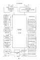
- FIG. 3 is a schematic diagram of the hardware structure of an electronic device provided by an embodiment of the application.
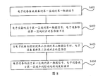
- FIG. 4 is a schematic flowchart of a touch screen control method provided by an embodiment of the application.
- FIG. 5 is a schematic diagram of the divided areas of a curved screen mobile phone according to an embodiment of the application.
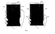
- FIG. 6 is a schematic diagram of a mobile phone with a curved screen provided by an embodiment of the application being held by a user;
- FIG. 7 is a schematic flowchart of another touch screen control method provided by an embodiment of the application.
- FIG. 8 is a schematic flowchart of another touch screen control method provided by an embodiment of the application.
- FIG. 9 is a schematic diagram of the touch principle of a curved screen mobile phone provided by an embodiment of the application.
- FIG. 10 is a schematic flowchart of another touch screen control method provided by an embodiment of the application.
- FIG. 11 is a schematic flowchart of another touch screen control method provided by an embodiment of the application.
- FIG. 12 is a schematic diagram of dividing areas of a folding screen mobile phone according to an embodiment of the application.
- FIG. 13 is a schematic diagram of a folding screen mobile phone provided by an embodiment of the application being held by a user;
- FIG. 14 is a schematic flowchart of another touch screen control method provided by an embodiment of the application.
- 15 is a schematic flowchart of another touch screen control method provided by an embodiment of the application.
- 16 is a schematic flowchart of another touch screen control method provided by an embodiment of the application.
- FIG. 17 is a schematic diagram of the composition of an electronic device provided by an embodiment of the application.
- At least one of a, b, or c can mean: a, b, c, a and b, a and c, b and c, or a and b and c, where a, b and c c can be single or multiple.
- words such as “first” and “second” are used to distinguish the same items or similar items that have substantially the same function and effect. Those skilled in the art can understand that words such as “first” and “second” do not limit the number and execution order.
- the "first” in the first application and the "second” in the second application in the embodiments of the present application are only used to distinguish different applications.
- the descriptions of the first, second, etc. appearing in the embodiments of this application are only used for illustration and distinguishing the description objects, and there is no order, and it does not mean that the number of devices in the embodiments of this application is particularly limited, and does not constitute a reference to this application. Any limitations of the embodiment.
- the embodiment of the present application provides a touch screen control method, which is applied to an electronic device, and when the electronic device is held by a user, the area touched by the user's finger is the touch area.
- the screen of the electronic device may be a curved screen with curved sides, or a folding screen.
- the embodiments of the present application do not limit the specific form of the screen of the electronic device.
- only the curved screen and the folding screen of the electronic device are used as examples for description. In practical applications, the screen of the electronic device may also be in other forms.
- the screen of the electronic device is a curved screen with curved sides.
- the electronic device is a mobile phone with a curved screen shown in Fig. 1.
- A) in FIG. 1 shows a perspective view of the curved screen mobile phone 100.
- B) in FIG. 1 shows a front view of the curved screen mobile phone 100.
- the screen of the mobile phone 100 is a curved screen with a curvature on the left side 10 and the right side 20.
- the screen of the curved screen mobile phone is a curved screen with a curved side; therefore, when the user holds the curved screen mobile phone, the user's finger will touch the side curved area of the screen in a large area.
- (c) in Figure 1 take the user's right hand holding a mobile phone with a curved screen as an example.
- the tiger's mouth and thumb of the user's right hand are in contact with the curved area on the right side of the curved screen, and the other fingers of the user's right hand are in contact with the curved area on the left side of the curved screen.
- the side arc area of the above-mentioned curved screen mobile phone can realize side interaction through special functions and gestures.
- the side arc area can realize functions such as volume adjustment and quick photo taking through gesture operations.
- the left or right hand of the user can be detected through the side arc area.
- the embodiment of the present application does not limit the specific function of the side arc area, and it is only an exemplary description here.
- the screen of the electronic device is a folding screen.
- the electronic device is a folding screen mobile phone.
- the folding screen mobile phones can be divided into two categories.
- One type is the folding screen that is turned outwards (referred to as the outer folding screen), and the other is the folding screen that is turned inward (referred to as the inner folding screen).
- the folding screen can be divided into a main screen and a sub screen as an example. After the internal folding folding screen is folded, the main screen and the secondary screen are opposite and invisible to the user. After the outward-folding folding screen is folded, the main screen and the secondary screen face away from each other and are visible to users.
- the folding screen may be folded up and down, or left and right, which is not limited in the embodiment of the present application. This is only the outer folding folding screen, and the left and right folding are taken as an example for description.
- FIG. 2 it is a schematic diagram of the product form of a mobile phone with an outward-folding folding screen provided by an embodiment of this application.
- (a) in FIG. 2 is a schematic diagram of the shape of the outward folding folding screen in a fully unfolded state.
- the outward-folding folding screen can be folded into a half-folded state as shown in (b) of FIG. 2, including a main screen, a secondary screen, and a side screen.
- the outward-folding folding screen can continue to be folded into the folding screen in the folded state shown in (c) of FIG. 2.
- (c) in Figure 2 after the folding screen mobile phone is completely folded, the main screen and the secondary screen are opposite and visible to the user.
- the touch screen of the folding screen mobile phone can touch the side screen in the folded state; therefore, when the user holds the folding screen mobile phone, the user's finger will touch the side area of the touch screen in a large area, and the user's palm will touch the main screen or the secondary screen.
- Figure 2 (d) taking the user's right hand holding a folding screen mobile phone as an example, the tiger's mouth and thumb of the user's right hand are in contact with the side screen area of the folding screen mobile phone.
- the main screen area touches, and the secondary screen of the folding screen mobile phone faces the user.
- the screen of the electronic device shown in FIG. 1 to FIG. 2 may be a capacitive touch screen.
- the capacitive touch screen can work through any object that holds an electric charge, including human skin.
- the capacitive touch screen may be a self-capacitance screen, a mutual-capacitance screen, or a touch screen that combines self-capacitance and mutual capacitance, which is not limited in the embodiment of the present application.
- only the capacitive touch screen is a mutual capacitive screen as an example for description.
- the mutual capacitance screen uses nano-indium tin oxide (ITO) to make horizontal and vertical electrodes on the surface of the glass.
- ITO nano-indium tin oxide
- the intersection of the two sets of electrodes will form a capacitance, that is, the two sets of electrodes are respectively The two poles of the capacitor are formed.
- the finger touches the capacitive screen it affects the coupling between the two electrodes near the touch point, thereby changing the capacitance between the two electrodes.
- the vertical electrodes sequentially send out excitation signals, and all the horizontal electrodes receive signals at the same time, and the capacitance value of the intersection of all the horizontal and vertical electrodes can be obtained, that is, the capacitance of the two-dimensional plane of the entire touch screen.
- the coordinates of each touch point can be calculated. It is understandable that the above electronic device may also send excitation signals sequentially through the horizontal electrodes, and all the vertical electrodes receive the signals at the same time, which is not limited in the embodiment of the present application.
- the electrode that sends out the excitation signal can be called the driving electrode, and the electrode that receives the signal can be called the receiving electrode.
- the touch principle of the capacitive screen when the user's finger touches the screen, the capacitance of the mutual capacitance is detected, and the capacitance is subtracted from the baseline to obtain the difference (rawdiff).
- the rawdiff exceeds the finger threshold, it can be determined that there is a finger touching the screen, and the number of fingers touching the screen and the location information touched by the user can be determined.
- the reference value is a value set according to the capacitance of the touch screen when it is not touched (can be called the background capacitance). Since the background capacitance of different areas on the touch screen is often not consistent, the reference value can usually be set on the touch screen.
- This application does not limit a certain value.
- the screen of an electronic device only sets a reference value.
- the capacitance value will dynamically change with multiple factors such as temperature, humidity, noise, and charger interference, so the reference value
- the value will also be dynamically updated with the change of the capacitance value, so that the electronic device can sensitively recognize the user's touch operation.
- the reference value will stop updating, otherwise the signal touched by the user will be updated together, and the touch detection cannot be continued. Therefore, when the electronic device is held by the user and the area touched by the user's finger is the touch area, the reference value will stop updating.
- the capacitance value of the capacitor will change due to the influence of environmental temperature, humidity, noise and other interference factors. If the reference value is not updated in time, it will cause the user to touch the screen abnormally. The user experience is poor.
- the touch screen of an electronic device is a curved screen with curved sides, or when the screen is folded, when the electronic device only maintains a reference value, when the user holds the electronic device, the user’s finger touches the touch screen and the reference value stops. Update. However, if the electronic device is affected by charging and the temperature is high, then the capacitance value of the capacitor will change greatly. If the reference value is not updated accordingly, it will cause the user to touch inflexibly or touch can not be recognized, resulting in poor user experience .
- the electronic device in the embodiment of the present application when the electronic device in the embodiment of the present application is held by the user, the area touched by the user's finger is the touch area.
- the electronic device can be a mobile phone, tablet computer, desktop, laptop, handheld computer, notebook computer, ultra-mobile personal computer (UMPC), netbook, and cellular phone, personal digital assistant (personal digital assistant). , PDA), augmented reality (augmented reality, AR) ⁇ virtual reality (VR) equipment, etc.
- PDA personal digital assistant
- augmented reality augmented reality, AR
- VR virtual reality
- the embodiments of the present application do not specifically limit the specific form of the electronic equipment.
- FIG. 3 is a schematic structural diagram of an electronic device 300 according to an embodiment of this application.
- the electronic device 300 may include a processor 310, an external memory interface 320, an internal memory 321, a universal serial bus (USB) interface 330, a charging management module 340, a power management module 341, and a battery 342 , Antenna 1, antenna 2, mobile communication module 350, wireless communication module 360, audio module 370, speaker 370A, receiver 370B, microphone 370C, earphone interface 370D, sensor module 380, buttons 390, motor 391, indicator 392, camera 393 , The display screen 394, and the subscriber identification module (SIM) card interface 395, etc.
- SIM subscriber identification module
- the sensor module 380 may include pressure sensor 380A, gyroscope sensor 380B, air pressure sensor 380C, magnetic sensor 380D, acceleration sensor 380E, distance sensor 380F, proximity light sensor 380G, fingerprint sensor 380H, temperature sensor 380J, touch sensor 380K, environment Light sensor 380L, bone conduction sensor 380M, etc.
- the structure illustrated in this embodiment does not constitute a specific limitation on the electronic device 300.
- the electronic device 300 may include more or fewer components than shown, or combine certain components, or split certain components, or arrange different components.
- the illustrated components can be implemented in hardware, software, or a combination of software and hardware.
- the processor 310 may include one or more processing units.
- the processor 310 may include an application processor (AP), a modem processor, a graphics processing unit (GPU), and an image signal processor. (image signal processor, ISP), controller, memory, video codec, digital signal processor (digital signal processor, DSP), baseband processor, and/or neural-network processing unit (NPU) Wait.
- the different processing units may be independent devices or integrated in one or more processors.
- the aforementioned AP, baseband processor, GPU, and NPU may be integrated in a system-on-chip (SOC).
- the aforementioned processor 310 may further include a touch integrated circuit (Integrated Circuit, IC).
- the touch IC can be used to execute the touch screen control method provided in the embodiments of the present application.
- the touch IC can be an independent chip or integrated in the SOC.
- the controller may be the nerve center and command center of the electronic device 300.
- the controller can generate operation control signals according to the instruction operation code and timing signals to complete the control of fetching and executing instructions.
- a memory may also be provided in the processor 310 to store instructions and data.
- the memory in the processor 310 is a cache memory.
- the memory can store instructions or data that have just been used or recycled by the processor 310. If the processor 310 needs to use the instruction or data again, it can be directly called from the memory. Repeated accesses are avoided, the waiting time of the processor 310 is reduced, and the efficiency of the system is improved.
- the processor 310 may include one or more interfaces.
- the interface can include an integrated circuit (inter-integrated circuit, I2C) interface, an integrated circuit built-in audio (inter-integrated circuit sound, I2S) interface, a pulse code modulation (pulse code modulation, PCM) interface, and a universal asynchronous transmitter (universal asynchronous) interface.
- I2C integrated circuit
- I2S integrated circuit built-in audio
- PCM pulse code modulation
- UART universal asynchronous transmitter
- MIPI mobile industry processor interface
- GPIO general-purpose input/output
- SIM subscriber identity module
- USB Universal Serial Bus
- the interface connection relationship between the modules illustrated in this embodiment is merely a schematic description, and does not constitute a structural limitation of the electronic device 300.
- the electronic device 300 may also adopt different interface connection modes in the foregoing embodiments, or a combination of multiple interface connection modes.
- the charging management module 340 is used to receive charging input from the charger.
- the charger can be a wireless charger or a wired charger.
- the charging management module 340 may receive the charging input of the wired charger through the USB interface 330.
- the charging management module 340 may receive the wireless charging input through the wireless charging coil of the electronic device 300. While the charging management module 340 charges the battery 342, it can also supply power to the electronic device through the power management module 341.
- the power management module 341 is used to connect the battery 342, the charging management module 340 and the processor 310.
- the power management module 341 receives input from the battery 342 and/or the charge management module 340, and supplies power to the processor 310, the internal memory 321, the external memory, the display screen 394, the camera 393, and the wireless communication module 360.
- the power management module 341 can also be used to monitor battery capacity, battery cycle times, battery health status (leakage, impedance) and other parameters.
- the power management module 341 may also be provided in the processor 310.
- the power management module 341 and the charging management module 340 may also be provided in the same device.
- the wireless communication function of the electronic device 300 can be implemented by the antenna 1, the antenna 2, the mobile communication module 350, the wireless communication module 360, the modem processor, and the baseband processor.
- the antenna 1 and the antenna 2 are used to transmit and receive electromagnetic wave signals.
- Each antenna in the electronic device 300 can be used to cover a single or multiple communication frequency bands. Different antennas can also be reused to improve antenna utilization.
- Antenna 1 can be multiplexed as a diversity antenna of a wireless local area network.
- the antenna can be used in combination with a tuning switch.
- the mobile communication module 350 can provide a wireless communication solution including 2G/3G/4G/5G and the like applied to the electronic device 300.
- the mobile communication module 350 may include at least one filter, a switch, a power amplifier, a low noise amplifier (LNA), and the like.
- the mobile communication module 350 can receive electromagnetic waves by the antenna 1, and perform processing such as filtering, amplifying and transmitting the received electromagnetic waves to the modem processor for demodulation.
- the mobile communication module 350 can also amplify the signal modulated by the modem processor, and convert it into electromagnetic waves for radiation by the antenna 1.
- at least part of the functional modules of the mobile communication module 350 may be provided in the processor 310.
- at least part of the functional modules of the mobile communication module 350 and at least part of the modules of the processor 310 may be provided in the same device.
- the modem processor may include a modulator and a demodulator.
- the modulator is used to modulate the low frequency baseband signal to be sent into a medium and high frequency signal.
- the demodulator is used to demodulate the received electromagnetic wave signal into a low-frequency baseband signal. Then the demodulator transmits the demodulated low-frequency baseband signal to the baseband processor for processing. After the low-frequency baseband signal is processed by the baseband processor, it is passed to the application processor.
- the application processor outputs sound signals through audio equipment (not limited to the speaker 370A, the receiver 370B, etc.), or displays images or video through the display screen 394.
- the modem processor may be an independent device. In other embodiments, the modem processor may be independent of the processor 310 and be provided in the same device as the mobile communication module 350 or other functional modules.
- the wireless communication module 360 can provide applications on the electronic device 300 including wireless local area networks (WLAN) (such as wireless fidelity (Wi-Fi) networks), bluetooth (BT), and global navigation satellites.
- WLAN wireless local area networks
- BT wireless fidelity
- GNSS global navigation satellite system
- FM frequency modulation
- NFC near field communication technology
- infrared technology infrared, IR
- the wireless communication module 360 may be one or more devices integrating at least one communication processing module.
- the wireless communication module 360 receives electromagnetic waves via the antenna 2, frequency modulates and filters the electromagnetic wave signals, and sends the processed signals to the processor 310.
- the wireless communication module 360 may also receive the signal to be sent from the processor 310, perform frequency modulation, amplify, and convert it into electromagnetic waves to radiate through the antenna 2.
- the antenna 1 of the electronic device 300 is coupled with the mobile communication module 350, and the antenna 2 is coupled with the wireless communication module 360, so that the electronic device 300 can communicate with the network and other devices through wireless communication technology.
- the wireless communication technology may include global system for mobile communications (GSM), general packet radio service (GPRS), code division multiple access (CDMA), broadband Code division multiple access (wideband code division multiple access, WCDMA), time-division code division multiple access (TD-SCDMA), long term evolution (LTE), BT, GNSS, WLAN, NFC , FM, and/or IR technology, etc.
- the GNSS may include global positioning system (GPS), global navigation satellite system (GLONASS), Beidou navigation satellite system (BDS), quasi-zenith satellite system (quasi -zenith satellite system, QZSS) and/or satellite-based augmentation systems (SBAS).
- GPS global positioning system
- GLONASS global navigation satellite system
- BDS Beidou navigation satellite system
- QZSS quasi-zenith satellite system
- SBAS satellite-based augmentation systems
- the electronic device 300 implements a display function through a GPU, a display screen 394, and an application processor.
- the GPU is a microprocessor for image processing, connected to the display screen 394 and the application processor.
- the GPU is used to perform mathematical and geometric calculations for graphics rendering.
- the processor 310 may include one or more GPUs that execute program instructions to generate or change display information.
- the display screen 394 is used to display images, videos, and the like.
- the display screen 394 is a touch screen.
- the touch screen is a curved screen with curved sides, or a folding screen.
- the display screen 394 includes a display panel.
- the display panel can adopt liquid crystal display (LCD), organic light-emitting diode (OLED), active matrix organic light-emitting diode or active-matrix organic light-emitting diode (active-matrix organic light-emitting diode).
- LCD liquid crystal display
- OLED organic light-emitting diode
- emitting diode AMOLED, flexible light-emitting diode (FLED), Miniled, MicroLed, Micro-oLed, quantum dot light-emitting diode (QLED), etc.
- the electronic device 300 can implement a shooting function through an ISP, a camera 393, a video codec, a GPU, a display screen 394, and an application processor.
- the ISP is used to process the data fed back by the camera 393. For example, when taking a picture, the shutter is opened, the light is transmitted to the photosensitive element of the camera through the lens, the light signal is converted into an electrical signal, and the photosensitive element of the camera transmits the electrical signal to the ISP for processing and is converted into an image visible to the naked eye.
- ISP can also optimize the image noise, brightness, and skin color. ISP can also optimize the exposure, color temperature and other parameters of the shooting scene.
- the ISP may be provided in the camera 393.
- the camera 393 is used to capture still images or videos.
- the object generates an optical image through the lens and is projected to the photosensitive element.
- the photosensitive element may be a charge coupled device (CCD) or a complementary metal-oxide-semiconductor (CMOS) phototransistor.
- CMOS complementary metal-oxide-semiconductor
- the photosensitive element converts the optical signal into an electrical signal, and then transfers the electrical signal to the ISP to convert it into a digital image signal.
- ISP outputs digital image signals to DSP for processing.
- DSP converts digital image signals into standard RGB, YUV and other formats of image signals.
- the electronic device 300 may include one or N cameras 393, and N is a positive integer greater than one.
- Digital signal processors are used to process digital signals. In addition to digital image signals, they can also process other digital signals. For example, when the electronic device 300 selects a frequency point, the digital signal processor is used to perform Fourier transform on the energy of the frequency point.
- Video codecs are used to compress or decompress digital video.
- the electronic device 300 may support one or more video codecs. In this way, the electronic device 300 can play or record videos in multiple encoding formats, such as: moving picture experts group (MPEG) 1, MPEG2, MPEG3, MPEG4, and so on.
- MPEG moving picture experts group
- MPEG2 MPEG2, MPEG3, MPEG4, and so on.
- NPU is a neural-network (NN) computing processor.
- NN neural-network
- the NPU can realize applications such as intelligent cognition of the electronic device 300, such as image recognition, face recognition, voice recognition, text understanding, and so on.
- the external memory interface 320 may be used to connect an external memory card, such as a Micro SD card, so as to expand the storage capacity of the electronic device 300.
- the external memory card communicates with the processor 310 through the external memory interface 320 to realize the data storage function. For example, save music, video and other files in an external memory card.
- the internal memory 321 may be used to store computer executable program code, where the executable program code includes instructions.
- the processor 310 executes various functional applications and data processing of the electronic device 300 by running instructions stored in the internal memory 321.
- the processor 310 may execute instructions stored in the internal memory 321 in response to the user's first operation or second operation on the display screen 394 (ie, the folding screen), and the display screen 384 ( That is, the folding screen) displays the corresponding display content.
- the internal memory 321 may include a storage program area and a storage data area. Among them, the storage program area can store an operating system, at least one application program (such as a sound playback function, an image playback function, etc.) required by at least one function.
- the storage data area can store data (such as audio data, phone book, etc.) created during the use of the electronic device 300.
- the internal memory 321 may include a high-speed random access memory, and may also include a non-volatile memory, such as at least one magnetic disk storage device, a flash memory device, a universal flash storage (UFS), and the like.
- the electronic device 300 can implement audio functions through an audio module 370, a speaker 370A, a receiver 370B, a microphone 370C, a headphone interface 370D, and an application processor. For example, music playback, recording, etc.
- the audio module 370 is used to convert digital audio information into an analog audio signal for output, and is also used to convert an analog audio input into a digital audio signal.
- the audio module 370 can also be used to encode and decode audio signals.
- the audio module 370 may be provided in the processor 310, or part of the functional modules of the audio module 370 may be provided in the processor 310.
- the speaker 370A also called “speaker” is used to convert audio electrical signals into sound signals.
- the electronic device 300 can listen to music through the speaker 370A, or listen to a hands-free call.
- the receiver 370B also called “earpiece”, is used to convert audio electrical signals into sound signals.
- the electronic device 300 When the electronic device 300 answers a call or voice message, it can receive the voice by bringing the receiver 370B close to the human ear.
- the microphone 370C also called “microphone” or “microphone”, is used to convert sound signals into electrical signals.
- the user can approach the microphone 370C through the mouth to make a sound, and input the sound signal into the microphone 370C.
- the electronic device 300 may be provided with at least one microphone 370C. In other embodiments, the electronic device 300 can be provided with two microphones 370C, which can implement noise reduction functions in addition to collecting sound signals. In other embodiments, the electronic device 300 may also be provided with three, four or more microphones 370C to collect sound signals, reduce noise, identify sound sources, and realize directional recording functions.
- the earphone interface 370D is used to connect wired earphones.
- the earphone interface 370D may be a USB interface 330, or a 3.5mm open mobile terminal platform (OMTP) standard interface, or a cellular telecommunications industry association (cellular telecommunications industry association of the USA, CTIA) standard interface.
- OMTP open mobile terminal platform
- CTIA cellular telecommunications industry association
- the pressure sensor 380A is used to sense pressure signals and can convert the pressure signals into electrical signals.
- the pressure sensor 380A may be provided on the display screen 394.
- the capacitive pressure sensor may include at least two parallel plates with conductive material. When a force is applied to the pressure sensor 380A, the capacitance between the electrodes changes.
- the electronic device 300 determines the intensity of the pressure according to the change in capacitance.
- the electronic device 300 detects the intensity of the touch operation according to the pressure sensor 380A.
- the electronic device 300 may also calculate the touched position according to the detection signal of the pressure sensor 380A.
- touch operations that act on the same touch position but have different touch operation strengths may correspond to different operation instructions. For example, when a touch operation whose intensity of the touch operation is less than the first pressure threshold is applied to the short message application icon, an instruction to view the short message is executed. When a touch operation with a touch operation intensity greater than or equal to the first pressure threshold acts on the short message application icon, an instruction to create a new short message is executed.
- the gyro sensor 380B may be used to determine the movement posture of the electronic device 300.
- the angular velocity of the electronic device 300 around three axes can be determined by the gyroscope sensor 380B.
- the gyro sensor 380B can be used for shooting anti-shake.
- the display 394 (ie, curved screen or folding screen) of the electronic device 300 may include a gyroscope sensor (such as the above-mentioned gyroscope sensor 380B) for measuring the orientation of the display screen 334 (ie, the direction vector of the orientation) .
- the orientation of the display screen 334 can be used to determine the angle between the display screen 334 and the horizontal plane.
- the electronic device can determine the angle between adjacent screens according to the measured angle change of the orientation of each screen.
- the magnetic sensor 380D includes a Hall sensor.
- the electronic device 300 can use the magnetic sensor 380D to detect the opening and closing of the flip holster.
- the acceleration sensor 380E can detect the magnitude of the acceleration of the electronic device 300 in various directions (generally three axes). When the electronic device 300 is stationary, the magnitude and direction of gravity can be detected.
- the electronic device 300 can measure the distance by infrared or laser.
- the electronic device 300 may measure the distance between the electronic device 300 and the human face through the distance sensor 380F.
- the proximity light sensor 380G may include, for example, a light emitting diode (LED) and a light detector, such as a photodiode.
- the light emitting diode may be an infrared light emitting diode.
- the electronic device 300 emits infrared light to the outside through the light emitting diode.
- the electronic device 300 uses a photodiode to detect infrared reflected light from nearby objects. When sufficient reflected light is detected, it can be determined that there is an object near the electronic device 300. When insufficient reflected light is detected, the electronic device 300 can determine that there is no object near the electronic device 300.
- the ambient light sensor 380L is used to sense the brightness of the ambient light.
- the electronic device 300 can adaptively adjust the brightness of the display screen 394 according to the perceived brightness of the ambient light.
- the ambient light sensor 380L can also be used to automatically adjust the white balance when taking pictures.
- the ambient light sensor 380L can also cooperate with the proximity light sensor 380G to detect whether the electronic device 300 is in the pocket to prevent accidental touch.
- the fingerprint sensor 380H is used to collect fingerprints.
- the electronic device 300 can use the collected fingerprint characteristics to implement fingerprint unlocking, access application locks, fingerprint photographs, fingerprint answering calls, and so on.
- the temperature sensor 380J is used to detect temperature.
- the electronic device 300 uses the temperature detected by the temperature sensor 380J to execute a temperature processing strategy. For example, when the temperature reported by the temperature sensor 380J exceeds a threshold value, the electronic device 300 executes to reduce the performance of the processor located near the temperature sensor 380J, so as to reduce power consumption and implement thermal protection.
- the electronic device 300 when the temperature is lower than another threshold, the electronic device 300 heats the battery 342 to avoid abnormal shutdown of the electronic device 300 due to low temperature.
- the electronic device 300 boosts the output voltage of the battery 342 to avoid abnormal shutdown caused by low temperature.
- Touch sensor 380K also called “touch panel”.
- the touch sensor 380K can be arranged on the display screen 394, and the touch screen is composed of the touch sensor 380K and the display screen 394, which is also called a “touch screen”.
- the touch sensor 380K is used to detect touch operations acting on or near it.
- the touch sensor can pass the detected touch operation to the application processor to determine the type of touch event.
- the visual output related to the touch operation can be provided through the display screen 394.
- the touch sensor 380K may also be disposed on the surface of the electronic device 300, which is different from the position of the display screen 394.
- the bone conduction sensor 380M can acquire vibration signals.
- the bone conduction sensor 380M can acquire the vibration signal of the vibrating bone mass of the human voice.
- the bone conduction sensor 380M can also contact the human pulse and receive blood pressure beating signals.
- the button 390 includes a power-on button, a volume button, and so on.
- the button 390 may be a mechanical button. It can also be a touch button.
- the electronic device 300 may receive key input, and generate key signal input related to user settings and function control of the electronic device 300.
- the motor 391 can generate vibration prompts. The motor 391 can be used for incoming call vibration notification, and can also be used for touch vibration feedback.
- the indicator 392 can be an indicator light, which can be used to indicate the charging status, power change, and can also be used to indicate messages, missed calls, notifications, and so on.
- the SIM card interface 395 is used to connect to the SIM card. The SIM card can be inserted into the SIM card interface 395 or pulled out from the SIM card interface 395 to achieve contact and separation with the electronic device 300.
- a touch screen control method provided by an embodiment of this application can be applied to the electronic device shown in FIG. 3.
- the area touched by the user’s finger is the touch area.
- the electronic device is a curved screen mobile phone as an example for description, and the method includes steps S401-S402.
- the electronic device receives a first touch signal in a first area of the screen.
- the screen of the electronic device includes a first area and a second area.
- the first area and the second area respectively correspond to a baseline
- the reference value corresponds to the capacitance value of the corresponding area when the area is not touched.
- the first reference value corresponds to the capacitance value of the first area when not being touched by the user.
- the electronic device detects the capacitance of the capacitor, and subtracts the first baseline from the capacitance to obtain a rawdiff.
- the reference value can be used to determine whether the screen of the electronic device is touched by the user.
- the finger thresholds set in the first area and the second area may be the same or different, which is not limited in the embodiment of the present application.
- the screen of the electronic device may further include an area other than the first area and the second area.
- the third area and so on may be divided into at least two areas, the at least two areas may constitute a complete screen of the electronic device, and the at least two areas include the first area and the second area.
- the above-mentioned first touch signal may be a user's touch operation or a touch signal when the user holds the electronic device.
- the electronic device clicks or slides the touch signal of the first area.
- the user touches the touch signal of the first area.
- the following embodiments only take the first touch signal as the touch signal when the user holds the electronic device as an example for description.
- each of the above regions does not overlap each other.
- the screen of the electronic device includes a first area and a second area
- the first area and the second area do not overlap each other.
- the screen of the electronic device includes a first area, a second area, and a third area
- the first area, the second area, and the third area do not overlap each other.
- the electronic device is a curved screen mobile phone with a curved side as shown in FIG. 1, and the screen of the electronic device may include a main control screen area and a side curved screen area.
- the screen of the electronic device may include a main control screen area, a first side curved screen area, and a second side curved screen area.
- the electronic device can divide the screen of a curved screen mobile phone into two areas, area 1 and area 2, where area 1 is the main control screen area and area 2 is the side In the curved screen area, the first area is area 1, and the second area is area 2.
- the electronic device can divide the screen of a curved screen mobile phone into three areas, area 1, area 2, and area 3. Among them, area 1 is the main control screen area, and area 2 is the curved screen area on the left side, area 3 is the curved screen area on the right side, the first area is area 3, the second area is area 1, and the third area is area 2.
- the embodiment of the present application does not limit the specific principle of dividing the screen of the electronic device, and only FIG. 5 is used as an example for illustration.
- each area corresponds to a reference value. That is, the electronic device can maintain multiple reference values, and the multiple reference values respectively correspond to different areas, and each area corresponds to a reference value. For example, taking the screen division method shown in (b) in Figure 5 as an example, the electronic device can maintain 3 baseline values, namely baseline 1, baseline 2, and baseline 3. Among them, area 1 corresponds to baseline 1, and area 2 corresponds to baseline 2, area 3 corresponds to baseline 3.
- the above-mentioned first area is an area touched by the user's hand when the electronic device is held by the user.
- the first area may be a side curved screen area; or, the first area may be at least one of the first side curved screen area and the second side curved screen area.
- the electronic device may receive the first touch signal of the user on the first area (area 2 in (a) in FIG. 6 or area 3 in (b) in FIG. 6).
- the electronic device In response to the first touch signal of the first area, the electronic device maintains the reference value corresponding to the first area unchanged.
- the electronic device responds to the user's grip on the first area (area 2), and the electronic device The device maintains the reference value corresponding to the first area (area 2) unchanged. That is, the electronic device does not update the baseline 2 corresponding to the area 2 touched when the user holds the electronic device.
- the electronic device responds to the user's holding operation on the first area (area 3), The electronic device maintains the reference value corresponding to the first area (area 3) unchanged. That is, the electronic device does not update the baseline 3 corresponding to the area 3 touched when the user holds the electronic device.
- the embodiment of the present application may maintain multiple reference values, and each area corresponds to a reference value.
- the electronic device does not update the reference value corresponding to the first area.
- the electronic device if the electronic device maintains only one reference value, when the user holds the area 3, the electronic device will stop updating the reference value. Then, when the capacitance value of the capacitor in the electronic device changes greatly with interference factors such as temperature, humidity, noise, etc., since the reference value stops updating, after the user touches the area 1 again, the capacitance and the reference value The difference (rawdiff) may not exceed the finger threshold, causing the electronic device to fail to recognize the user's touch operation. However, in this embodiment, by setting three baselines for each of the three areas, while the user is holding the area 3, when the user touches the area 1, the electronic device does not update the baseline 3 corresponding to the area 3.
- the electronic device Since area 1 corresponds to baseline1 and area 2 corresponds to baseline2, the electronic device does not update baseline3 corresponding to area 3, which will not cause any impact on baseline1 corresponding to area 1 and baseline2 corresponding to area 2. For example, the electronic device may continue to update baseline1 corresponding to area 1 and baseline2 corresponding to area 2.
- the electronic device can quickly recognize the above-mentioned touch operation by comparing it with the finger threshold based on the rawdiff between the capacitance and the reference value.
- the touch screen control method receives a user's first touch signal on a first area of the screen through an electronic device; wherein, the screen of the electronic device includes a first area and a second area, and each area corresponds to one A baseline, which corresponds to the capacitance value when the corresponding area is not touched; the electronic device responds to the first touch signal of the first area, and the electronic device maintains the reference value corresponding to the first area unchanged.
- the electronic device by maintaining multiple reference values, it is possible to stop updating the reference value corresponding to the first area when the user holds the first area.
- the electronic device stops updating the user
- the reference value corresponding to the first area is touched
- the reference value corresponding to the second area can be continuously updated, so that the electronic device can quickly and accurately recognize the user's touch operation on the second area, and improve user experience.
- an embodiment of the present application also provides a touch screen control method. As shown in FIG. 7, based on the above steps S401-S402, S403 may be further included.
- the second touch signal may be a user's touch operation on the second area, for example, an operation such as clicking or sliding.
- the electronic device responds to the user's touch on the first area (area 2), the electronic device The reference value corresponding to the first area (area 2) is maintained unchanged; the electronic device does not detect the touch signal of the second area (area 1), and the reference value corresponding to the second area (area 1) is updated. That is, the electronic device does not update the baseline 2 corresponding to the area 2 touched by the user, but updates the baseline 1 corresponding to the area 1 not touched by the user.
- the above step S403 can also be extended to: when the electronic device does not detect the second touch signal and the third area of the second area
- the electronic device updates the reference values of the second area and the third area respectively. That is, when the user does not touch the second area and the third area, the electronic device can update the reference values corresponding to the second area and the third area respectively.
- the electronic device responds to the user's touch operation on the first area (area 3).
- the device maintains the reference value corresponding to the first area (area 3) unchanged; the electronic device does not detect the touch signal of the second area (area 1) and the third area (area 2), and updates the second area (area 1) and The reference value corresponding to the third area (area 2). That is, the electronic device does not update the baseline 3 corresponding to the area 3 touched by the user, and respectively updates the baseline 1 corresponding to the area 1 and the baseline 2 corresponding to the area 2 that are not touched by the user.
- the union of area 1 and area 2 in (b) in FIG. 5 can also be used as the second area.
- the embodiment of the present application may maintain multiple reference values, and each area corresponds to a reference value.
- the electronic device does not update the reference value corresponding to the first area, and when the user does not touch the second area, the electronic device updates the reference value corresponding to the second area. Therefore, when the user touches the first area, since the reference value of the second area is dynamically updated with the capacitance of the second area, when the user touches the second area again, the electronic device can sensitively recognize the user’s Touch operation in the second area.
- the electronic device if the electronic device maintains only one reference value, when the user holds the area 3, the electronic device will stop updating the reference value. Then, when the capacitance value of the capacitance in the electronic device changes greatly with interference factors such as temperature, humidity, noise, etc., the reference value stops updating, so after the user touches the area 1, the difference between the capacitance and the reference value The value (rawdiff) may not exceed the finger threshold, thus causing the problem that the electronic device cannot recognize the user's touch operation.
- the electronic device by setting three baselines for each of the three areas, when the user holds the area 3, the electronic device does not update the baseline3 corresponding to the area 3, but updates the baseline1 corresponding to the area 1 and the baseline2 corresponding to the area 2.
- the electronic device can quickly recognize the above-mentioned touch operation by comparing it with the finger threshold based on the rawdiff between the capacitance and the reference value.
- the above-mentioned electronic device can update the reference value of area 1 and area 2 with the same update principle.
- the reference value 1 of area 1 and the reference value 2 of area 2 will be dynamically updated with the change of the capacitance value of area 1 and area 2, so that when the user touches area 1 and area 2, area 1 and area 2 will be updated dynamically.
- Area 2 can recognize the user's touch operation.
- the touch screen control method receives a user's first touch signal on a first area of the screen through an electronic device; wherein, the screen of the electronic device includes a first area and a second area, and each area corresponds to one A baseline, which corresponds to the capacitance value when its corresponding area is not touched; when the electronic device responds to the first touch signal of the first area, the electronic device maintains the reference value corresponding to the first area unchanged; when When the electronic device does not detect the second touch signal of the second area, the electronic device updates the reference value corresponding to the second area.
- an embodiment of the present application further provides a touch screen control method. As shown in FIG. 8, in addition to the above steps S401-S403, step S404 may also be included.
- the electronic device In response to the first touch signal in the first area, the electronic device reduces the emission frequency of the driving electrode in the first area.
- the electronic device responds to the user's grip on the first area (area 3), and the electronic device can reduce the frequency at which the driving electrodes in the first area emit excitation signals, Thereby reducing the power consumption of the screen.
- a capacitor will be formed at the intersection of the horizontal electrode and the vertical electrode in the screen of the electronic device, and the above-mentioned driving electrode may be the vertical electrode in FIG. 9 or the horizontal electrode in FIG. 9.
- the driving electrode is a vertical electrode
- the receiving electrode is a horizontal electrode.
- the driving electrode is a horizontal electrode
- the receiving electrode is a vertical electrode.
- the driving electrodes send out excitation signals in turn, and the receiving electrodes receive signals at the same time, and the capacitance value of the intersection of all the horizontal and vertical electrodes can be obtained.
- This embodiment does not limit the directions of the driving electrodes and the receiving electrodes of the electronic device.
- the driving electrodes in the screen of the electronic device shown in FIG. 9 are vertical electrodes and the receiving electrodes are horizontal electrodes as an example for description.
- the electronic device when the user holds the area 3, in response to the user's first touch signal to the area 3, the electronic device can reduce the frequency at which the drive electrodes in the area 3 emit excitation signals, that is, the electronic device reduces The vertical electrodes in area 3 emit the excitation signal frequency, thereby reducing the power consumption of the screen of the electronic device.
- the electronic device when the user holds the area 3, the electronic device can reduce the emission frequency of the longitudinal electrodes in the area 3 from 120 Hz to 30 Hz or even lower, thereby reducing the overall power consumption of the screen.
- the embodiment of the present application does not limit the amplitude of the frequency reduction of the driving electrode, which is only an exemplary description here.
- the touch screen control method receives a user's first touch signal on a first area of the screen through an electronic device; wherein, the screen of the electronic device includes a first area and a second area, and each area corresponds to one A baseline, which corresponds to the capacitance value when its corresponding area is not touched; when the electronic device responds to the first touch signal of the first area, the electronic device maintains the reference value corresponding to the first area unchanged; when When the electronic device does not detect the second touch signal in the second area, the electronic device updates the reference value corresponding to the second area; the electronic device responds to the first touch signal in the first area, and the electronic device reduces the drive electrode in the first area The transmit frequency.
- this embodiment by maintaining multiple reference values, it is possible to stop updating the reference value corresponding to the first area when the user touches the first area, and to update the reference value corresponding to the second area when the user does not touch the second area. This enables the electronic device to quickly and accurately recognize the user's touch operation on the second area, and enhance the user experience. Moreover, this embodiment can save the power consumption of the screen of the electronic device by reducing the emission frequency of the driving electrode in the first area.
- the above touch screen control method is after steps S401-S404, and the above may further include step S405.
- the electronic device may restore the emission frequency of the driving electrode in the first area to the normal frequency. For example, when the user no longer holds the area 3, the emission frequency of the drive electrodes in the area 3 will be restored to 120 Hz to ensure that when the user touches the area 3 again, the electronic device can quickly recognize the user's touch operation.
- the touch screen control method receives a user's first touch signal on a first area of the screen through an electronic device; wherein, the screen of the electronic device includes a first area and a second area, and each area corresponds to one A baseline, which corresponds to the capacitance value when its corresponding area is not touched; when the electronic device responds to the first touch signal of the first area, the electronic device maintains the reference value corresponding to the first area unchanged; when When the electronic device does not detect the second touch signal in the second area, the electronic device updates the reference value corresponding to the second area; the electronic device responds to the first touch signal in the first area, and the electronic device reduces the drive electrode in the first area When the first area is not held by the user, the electronic device restores the transmission frequency of the driving electrode in the first area.
- the electronic device by maintaining multiple reference values, it is possible to stop updating the reference value corresponding to the first area when the user touches the first area, and to update the reference value corresponding to the second area when the user does not touch the second area.
- This enables the electronic device to quickly and accurately recognize the user's touch operation on the second area, and enhance the user experience.
- the user touches the first area by reducing the emission frequency of the driving electrodes in the first area, the power consumption of the screen of the electronic device can be saved, and when the user no longer touches the first area, by restoring the first area.
- the emission frequency of the driving electrodes in a region can ensure that when the user touches the first region again, the electronic device can quickly recognize the user's touch operation on the first region.
- the embodiment of the present application provides yet another touch screen control method, which can be applied to a foldable electronic device.
- the touch screen control method includes steps S1101-S1102.
- the electronic device receives the first touch signal of the first area of the screen.
- the screen of the electronic device includes a first area and a second area.
- the first area and the second area respectively correspond to a baseline, and the reference value and its corresponding area are different from each other.
- the capacitance value when touched corresponds to the capacitance value when touched.
- the screen of the electronic device may include a main screen area, a secondary screen area, and a side screen area.
- the electronic device can divide the screen of a folding screen mobile phone into three areas, namely area 1, area 2, and area 3. Area 1 is the main screen area, area 2 is the secondary screen area, and area 3. Is the side screen area.
- the embodiment of the present application does not limit the principle of dividing at least two regions, and only FIG. 12 is taken as an example for illustration.
- the first area may be at least one area of the main screen area, the sub-screen area, and the side screen area.
- the above-mentioned electronic device being in the folded state refers to a state where the angle between the main screen and the secondary screen of the electronic device is smaller than the first preset angle threshold.
- the first preset angle threshold For example, take the first preset angle threshold of 30° as an example.
- the state where the angle ⁇ between the main screen and the secondary screen of the electronic device is less than 30° is the folded state.
- the electronic device can determine the angle between the main screen and the secondary screen according to the gyroscope sensor 380B and/or the acceleration sensor 380E in FIG. 3.
- the electronic device can measure the orientation of the main screen and the sub-screen (that is, the direction vector) according to the gyroscope sensors of the main screen and the sub-screen, and then determine the main screen and the sub-screen according to the measured angle change of the orientation of the main screen and the sub-screen.
- the included angle of the secondary screen The embodiment of the present application does not limit the specific value of the first preset angle threshold, and only 30° is exemplified here.
- each of the above-mentioned regions corresponds to a reference value. That is, when the electronic device is in the folded state, the electronic device can maintain multiple reference values, the multiple reference values respectively correspond to different areas, and each area corresponds to a reference value. For example, taking the above-mentioned at least two areas according to the division method shown in Figure 12 as an example, the electronic device can maintain 3 baseline values, namely baseline 1, baseline 2, and baseline 3. Among them, area 1 corresponds to baseline 1, and area 2 corresponds to baseline 2, area 3 corresponds to baseline 3.
- the tiger’s mouth and thumb of the user’s right hand touch the side screen area (area 3) of the folding screen mobile phone, and the palm of the user’s right hand is in contact with the main screen area (area 3) of the folding screen mobile phone.
- the first area is area 1 and area 3.
- the electronic device may receive the first touch signal of the user on the first area (area 1 and area 3 in FIG. 13).
- the electronic device when the electronic device is in the folded state, the electronic device responds to the user's first touch signal on the first area (area 1 and area 3), and the electronic device maintains the first area (area The reference values of 1 and 3) remain unchanged. That is, the electronic device does not update the baseline 1 of area 1 and the baseline 3 of area 3 held by the user.
- the electronic device will stop updating the reference value when the user holds the area 1 and the area 3. Then, when the capacitance value of the capacitor in the electronic device changes greatly with interference factors such as temperature, humidity, noise, etc., since the reference value stops updating, the user performs a touch operation (for example, a click operation or a sliding operation) on the area 2 Etc.), the difference between the capacitance and the reference value (rawdiff) may not exceed the finger threshold, which causes the problem that the electronic device cannot recognize the user's click operation.
- a touch operation for example, a click operation or a sliding operation
- the electronic device does not update the baseline 1 corresponding to the area 1 and the baseline 3 corresponding to the area 3. Because the area 2 corresponds to the baseline2, the electronic device can update the baseline 1 corresponding to the area 1 and the baseline3 corresponding to the area 3 without updating, and it will not have any impact on the baseline2 corresponding to the area 2. For example, the electronic device may continue to update baseline2 corresponding to area 2.
- the electronic device can quickly recognize the touch operation by comparing it with the finger threshold based on the rawdiff between the capacitance and the reference value.
- the touch screen control method receives a user's first touch signal on a first area of the screen through an electronic device; wherein, the screen of the electronic device includes a first area and a second area, and the electronic device is in a folded state.
- each area corresponds to a reference value, which corresponds to the capacitance value of the corresponding area when it is not touched; in the case of the electronic device in the folded state, it responds to the first touch signal of the first area , The electronic device maintains the reference value corresponding to the first area unchanged.
- the electronic device by maintaining multiple reference values when the electronic device is in the folded state, it is possible to stop updating the reference value corresponding to the first area when the user holds the first area, because the second area corresponds to another reference value. Therefore, when the electronic device stops updating the reference value corresponding to the first area touched by the user, the reference value corresponding to the second area can continue to be updated, so that the electronic device can quickly and accurately recognize the user’s touch operation on the second area. Improve user experience.
- an embodiment of the present application also provides a touch screen control method. As shown in FIG. 14, based on the above steps S1101-S1102, S1103 may also be included.
- the second touch signal may be a user's touch operation on the second area, for example, an operation such as clicking or sliding.
- the electronic device when the electronic device is in the folded state, the electronic device responds to the user's first touch signal on the first area (area 1 and area 3), and the electronic device maintains the first area (area The reference value of 1 and area 3) remains unchanged; when the electronic device does not detect the touch signal of the second area (area 2), the reference value of the second area (area 2) is updated. That is, the electronic device does not update the baseline 1 of the area 1 and the baseline 3 of the area 3 touched by the user, but updates the baseline 2 corresponding to the area 2 not touched by the user.
- the electronic device when the electronic device is in the folded state, multiple reference values can be maintained.
- the electronic device When the user touches the first area, the electronic device does not update the reference value corresponding to the first area. In the second area, the electronic device updates the reference value corresponding to the second area. Therefore, when the user touches the first area, since the reference value of the second area is dynamically updated with the capacitance value of the capacitance of the second area, when the user operates the second area again, the electronic device can sensitively recognize the user’s Touch operation in the second area.
- the electronic device by setting three baselines for each of the three areas, when the user holds area 1 and area 3, the electronic device does not update the baseline 1 corresponding to area 1 and the baseline 3 corresponding to area 3, but update area 2 corresponds to The baseline2.
- the capacitance value of the capacitor in area 2 changes greatly with interference factors such as temperature, humidity, noise, etc.
- the baseline2 corresponding to this area 2 is dynamically updated with the change of the capacitance value
- the electronic device can quickly recognize the touch operation by comparing it with the finger threshold based on the rawdiff between the capacitance and the reference value.
- the touch screen control method receives a user's first touch signal on a first area of the screen through an electronic device; wherein, the screen of the electronic device includes a first area and a second area, and the electronic device is in a folded state.
- each area corresponds to a reference value, which corresponds to the capacitance value of the corresponding area when it is not touched; in the case of the electronic device in the folded state, it responds to the first touch signal of the first area ,
- the electronic device maintains the reference value corresponding to the first area unchanged; when the electronic device is in the folded state, when the electronic device does not detect the second touch signal of the second area, the electronic device updates the reference value corresponding to the second area .
- the electronic device by maintaining multiple reference values when the electronic device is in the folded state, it is possible to stop updating the reference value corresponding to the first area when the user is holding the first area, and to update the reference value when the user does not touch the second area.
- the reference value corresponding to the second area can thereby enable the electronic device to quickly and accurately recognize the user's touch operation on the second area, and improve user experience.
- an embodiment of the present application further provides a touch screen control method. As shown in FIG. 15, based on the above steps S1101-S1103, S1104 may also be included.
- S1104 When the electronic device is in a folded state, the electronic device responds to the first touch signal in the first area, and the electronic device reduces the emission frequency of the driving electrode in the first area.
- the electronic device when the electronic device is in a folded state, the electronic device responds to the user's first touch signal to the first area (area 1 and area 3), and the electronic device can reduce the area 1 and The driving electrode in area 3 sends out the frequency of the excitation signal, thereby reducing the power consumption of the screen.
- a capacitor will be formed at the intersection of the horizontal electrode and the vertical electrode in the screen of the electronic device, and the above-mentioned driving electrode may be a vertical electrode or a horizontal electrode.
- the driving electrode is a vertical electrode
- the receiving electrode is a horizontal electrode.
- the driving electrode is a horizontal electrode
- the receiving electrode is a vertical electrode.
- the driving electrodes send out excitation signals in turn, and the receiving electrodes receive signals at the same time, and the capacitance value of the intersection of all the horizontal and vertical electrodes can be obtained.
- This embodiment does not limit the directions of the driving electrodes and the receiving electrodes of the electronic device.
- only the driving electrodes in the screen of the electronic device are vertical electrodes and the receiving electrodes are horizontal electrodes as an example for description.
- the electronic device when the electronic device is in a folded state, when the user holds area 1 and area 3, in response to the user's first touch signal to area 1 and area 3, the electronic device can lower the area 1 and area 3.
- the frequency at which the drive electrodes in area 3 emit excitation signals that is, the electronic device reduces the frequency at which the longitudinal electrodes in areas 1 and 3 in FIG. 1 emit excitation signals, thereby reducing the power consumption of the screen of the electronic device.
- the electronic device when the user touches area 1 and area 3, the electronic device can reduce the emission frequency of the longitudinal electrodes in area 1 and area 3 from 120 Hz to 30 Hz or even lower, thereby reducing the overall power consumption of the screen.
- the embodiment of the present application does not limit the amplitude of the frequency reduction of the driving electrode, which is only an exemplary description here.
- the electronic device can also stop scanning of the driving electrodes in the area 1 and the area 3.
- the scanning of the driving electrodes in the area 1 and the area 3 is resumed.
- the touch screen control method receives a user's first touch signal on a first area of the screen through an electronic device; wherein, the screen of the electronic device includes a first area and a second area, and the electronic device is in a folded state.
- each area corresponds to a reference value, which corresponds to the capacitance value of the corresponding area when it is not touched; in the case of the electronic device in the folded state, it responds to the first touch signal of the first area , The electronic device maintains the reference value corresponding to the first area unchanged; when the electronic device is in the folded state, when the electronic device does not detect the second touch signal of the second area, the electronic device updates the reference value corresponding to the second area When the electronic device is in a folded state, the electronic device responds to the first touch signal in the first area, and the electronic device reduces the emission frequency of the driving electrode in the first area.
- this embodiment by maintaining multiple reference values when the electronic device is in the folded state, it is possible to stop updating the reference value corresponding to the first area when the user is holding the first area, and to update the reference value when the user does not touch the second area.
- the reference value corresponding to the second area can thereby enable the electronic device to quickly and accurately recognize the user's touch operation on the second area, and improve user experience.
- this embodiment can save the power consumption of the screen of the electronic device by reducing the emission frequency of the driving electrode in the first area.
- the above touch screen control method may further include step S1105 when the user no longer touches the first area after steps S1101-S1104, or the electronic device is in an expanded state.
- the electronic device may restore the emission frequency of the driving electrode in the first area to the normal frequency. For example, when the user no longer holds area 1 and area 3, the emission frequency of the drive electrodes in area 1 and area 3 will be restored to 120Hz to ensure that when the user touches the area 1 and area 3 again, the electronic device can quickly identify the user Touch operation.
- the electronic device when the electronic device is in the unfolded state, the electronic device can restore the emission frequency of the driving electrode in the first area to the normal frequency, so that when the user touches the screen of the electronic device, the electronic device can quickly recognize the user's touch operation.
- the above-mentioned electronic device being in the unfolded state refers to a state where the angle between the main screen and the secondary screen of the electronic device is greater than or equal to the second preset angle threshold.
- the second preset angle threshold is greater than or equal to the first preset angle threshold.
- the state where the angle ⁇ between the main screen and the secondary screen of the electronic device is greater than or equal to 45° is the expanded state.
- the above-mentioned at least two regions correspond to a reference value. That is, when the electronic device is in the unfolded state, the electronic device only maintains one reference value, and this reference value is recorded as the first reference value.
- the above-mentioned at least two regions correspond to a reference value. That is, when the electronic device is in the unfolded state, the electronic device can maintain one reference value, and when the electronic device is in the folded state, the electronic device can maintain multiple reference values.
- the touch screen control method receives a user's first touch signal on a first area of the screen through an electronic device; wherein, the screen of the electronic device includes a first area and a second area, and the electronic device is in a folded state.
- each area corresponds to a reference value, which corresponds to the capacitance value of the corresponding area when it is not touched; in the case of the electronic device in the folded state, it responds to the first touch signal of the first area , The electronic device maintains the reference value corresponding to the first area unchanged; when the electronic device is in the folded state, when the electronic device does not detect the second touch signal of the second area, the electronic device updates the reference value corresponding to the second area
- the electronic device responds to the first touch signal in the first area, and the electronic device reduces the emission frequency of the driving electrode in the first area; it is not held by the user in the first area, or When the electronic device is in the unfolded state, the electronic device restores the emission frequency of the driving electrode in the first area.
- this embodiment by maintaining multiple reference values when the electronic device is in the folded state, it is possible to stop updating the reference value corresponding to the first area when the user is holding the first area, and to update the reference value when the user does not touch the second area.
- the reference value corresponding to the second area can thereby enable the electronic device to quickly and accurately recognize the user's touch operation on the second area, and improve user experience.
- this implementation can save the power consumption of the screen of the electronic device by reducing the emission frequency of the driving electrode in the first area, and restore the power consumption of the first area when the user no longer touches the first area or the electronic device is in the unfolded state.
- the emission frequency of the driving electrode can ensure that when the user touches the first area again, the electronic device can quickly recognize the user's touch operation on the first area.
- the embodiment of the present application may divide the above-mentioned electronic device into functional modules according to the above-mentioned method examples.
- each function module may be divided corresponding to each function, or two or more functions may be integrated into one processing module.
- the above-mentioned integrated modules can be implemented in the form of hardware or software function modules. It should be noted that the division of modules in the embodiments of the present application is illustrative, and is only a logical function division, and there may be other division methods in actual implementation.
- FIG. 17 shows a schematic diagram of a possible structure of the electronic device involved in the foregoing embodiment.
- the electronic device 1700 includes a processing unit 1701 and a storage unit 1702.
- the processing unit 1701 is used to control and manage the actions of the electronic device 1700.
- it can be used to perform the processing steps of S401-S402 in Figure 4; or it can be used to perform the processing steps of S401-S403 in Figure 7; or it can be used to perform the processing steps of S401-S404 in Figure 8.
- it can be used to perform the processing steps of S401-S405 in Figure 10; or, it can be used to perform the processing steps of S1101-S1102 in Figure 11; or, it can be used to perform the processing of S1101-S1103 in Figure 14.
- Steps; or, can be used to execute the processing steps of S1101-S1104 in FIG. 15; or, can be used to execute the processing steps of S1101-S1105 in FIG. 16; and/or other processes used in the technology described herein.
- the storage unit 1702 is used to store the program code and data of the electronic device 1700. For example, it can be used to store reference values.
- the unit modules in the aforementioned electronic device 1700 include but are not limited to the aforementioned processing unit 1701 and storage unit 1702.
- the electronic device 1700 may also include an audio unit, a communication unit, and the like.
- the audio unit is used to collect the voice uttered by the user and play the voice.
- the communication unit is used to support communication between the electronic device 1700 and other devices.
- the processing unit 1701 may be a processor or a controller, such as a touch IC, a central processing unit (CPU), a digital signal processor (digital signal processor, DSP), and an application-specific integrated circuit (application-specific integrated circuit). circuit, ASIC), field programmable gate array (FPGA) or other programmable logic devices, transistor logic devices, hardware components, or any combination thereof.
- the processor may include an application processor and a baseband processor. It can implement or execute various exemplary logical blocks, modules, and circuits described in conjunction with the disclosure of this application.
- the processor may also be a combination of computing functions, such as a combination of one or more microprocessors, a combination of a DSP and a microprocessor, etc.
- the storage unit 1702 may be a memory.
- the audio unit may include a microphone, a speaker, and so on.
- the communication unit may be a transceiver, a transceiver circuit, or a communication interface.
- the processing unit 1701 is a processor (the processor 310 shown in FIG. 3), and the storage unit 1702 may be a memory (the internal memory 321 shown in FIG. 3).
- the audio unit may include a speaker (the speaker 370A shown in FIG. 3) and a microphone (the microphone 370C shown in FIG. 3).
- the communication unit includes a wireless communication module (the wireless communication module 360 shown in FIG. 3). Wireless communication modules can be collectively referred to as communication interfaces.
- the electronic device 1700 provided in the embodiment of the present application may be the electronic device 300 shown in FIG. 3. Wherein, the foregoing processor, memory, and communication interface may be coupled together, for example, connected by a bus.
- the embodiment of the present application also provides a computer storage medium in which computer program code is stored.
- the electronic device executes FIG. 4, FIG. 7, FIG. 8, FIG. 10, and FIG. 11.
- the relevant method steps in Fig. 14, Fig. 15 or Fig. 16 implement the method in any of the foregoing embodiments.
- the embodiment of the present application also provides a computer program product, which when the computer program product runs on a computer, causes the computer to execute Figure 4, Figure 7, Figure 8, Figure 10, Figure 11, Figure 14, Figure 15 or Figure 16.
- Figure 4 Figure 7, Figure 8, Figure 10, Figure 11, Figure 14, Figure 15 or Figure 16.
- An embodiment of the present application also provides a circuit system for controlling a touch screen.
- the touch screen includes a first area and a second area.
- the first area and the second area respectively correspond to a reference value, and the reference value and its corresponding area are not
- the circuit system includes a processing unit, which is used to implement the relevant method steps in Figure 4, Figure 7, Figure 8, Figure 10, Figure 11, Figure 14, Figure 15 or Figure 16 The method in any of the above embodiments.
- the electronic device 1700, the computer storage medium, the computer program product, and the circuit system for controlling the touch screen provided in the embodiments of the present application are all used to execute the corresponding methods provided above, and therefore, the beneficial effects that can be achieved can be achieved. Refer to the beneficial effects in the corresponding methods provided above, which will not be repeated here.
- the steps of the method or algorithm described in combination with the disclosure of this application can be implemented in a hardware manner, or can be implemented in a manner in which a processor executes software instructions.
- Software instructions can be composed of corresponding software modules, which can be stored in random access memory (Random Access Memory, RAM), flash memory, erasable programmable read-only memory (Erasable Programmable ROM, EPROM), and electrically erasable Programmable read-only memory (Electrically EPROM, EEPROM), register, hard disk, mobile hard disk, CD-ROM or any other form of storage medium known in the art.
- An exemplary storage medium is coupled to the processor, so that the processor can read information from the storage medium and can write information to the storage medium.
- the storage medium may also be an integral part of the processor.
- the processor and the storage medium may be located in the ASIC.
- the ASIC may be located in the core network interface device.
- the processor and the storage medium may also exist as discrete components in the core network interface device.
- the functions described in this application can be implemented by hardware, software, firmware, or any combination thereof. When implemented by software, these functions can be stored in a computer-readable medium or transmitted as one or more instructions or codes on the computer-readable medium.
- the computer-readable medium includes a computer storage medium and a communication medium, where the communication medium includes any medium that facilitates the transfer of a computer program from one place to another.
- the storage medium may be any available medium that can be accessed by a general-purpose or special-purpose computer.
Landscapes
- Engineering & Computer Science (AREA)
- Theoretical Computer Science (AREA)
- General Engineering & Computer Science (AREA)
- Physics & Mathematics (AREA)
- General Physics & Mathematics (AREA)
- Human Computer Interaction (AREA)
- Computer Hardware Design (AREA)
- Signal Processing (AREA)
- Mathematical Physics (AREA)
- User Interface Of Digital Computer (AREA)
Abstract
一种触控屏控制方法和电子设备,涉及通信技术领域,解决了现有技术中电子设备仅维护一个基准值,造成用户触摸异常,用户体验不佳的问题。触控屏包括第一区域和第二区域,第一区域和第二区域分别对应一个基准值,基准值与其对应的区域未被触摸时的电容值相对应,方法包括:电子设备接收屏幕的第一区域的第一触摸信号(S401);电子设备响应于第一区域的第一触摸信号,电子设备维持第一区域对应的基准值不变(S402)。
Description
本申请要求于2019年09月19日提交国家知识产权局、申请号为201910889275.8、申请名称为“一种触控屏控制方法和电子设备”的中国专利申请的优先权,其全部内容通过引用结合在本申请中。
本申请实施例涉及通信技术领域,尤其涉及一种触控屏控制方法和电子设备。
随着终端设备的屏幕形态的发展,现有的终端设备的屏幕形态包括全面屏、侧边曲面屏、折叠屏等。现有的一种屏幕触控方法,整个屏幕的触控算法是通过一个基准值(baseline)来维护的,通过检测该基准值的变化来识别用户的点击、滑动等触摸操作。一旦用户触摸到屏幕,这个基准值就不会再更新,直到用户的手指离开屏幕。
但是,现有的屏幕触控方法,在终端设备被用户握持时,用户手指接触的区域为触摸区域的情况下,在用户抓握终端设备时,基准值停止更新。但是,在用户抓握终端设备的过程中,受环境温度、湿度、噪声等因素的影响,电容的容值可能发生较大变化,如果基准值不及时更新,将会出现用户触摸异常的情况发生,用户体验不佳。
发明内容
本申请实施例提供一种触控屏控制方法和电子设备,能够避免用户触摸异常的情况发生,提升用户体验。
为达到上述目的,本申请实施例采用如下技术方案:
本申请实施例的第一方面,提供一种触控屏控制方法,该触控屏包括第一区域和第二区域,该第一区域和第二区域分别对应一个基准值,该基准值与其对应的区域未被触摸时的电容值相对应,该方法包括:电子设备接收第一区域的第一触摸信号;响应于该第一触摸信号,该电子设备维持该第一区域对应的基准值不变。基于本方案,通过维护多个基准值,能够在用户握持第一区域时,停止更新该第一区域对应的基准值,由于第二区域对应的是另一个基准值,因此,电子设备停止更新用户触摸的第一区域对应的基准值时,第二区域对应的基准值可以继续更新,从而能够使得电子设备能够快速准确的识别用户对第二区域的触摸操作,提升用户体验。
结合第一方面,在第一种可能的实现方式中,上述方法还包括:当电子设备未检测到上述第二区域的第二触摸信号时,电子设备更新第二区域对应的基准值。基于本方案,通过维护多个基准值,能够在用户触摸第一区域时,停止更新该第一区域对应的基准值,在用户未触摸第二区域时,更新第二区域对应的基准值,从而能够使得电子设备能够快速准确的识别用户对第二区域的触摸操作,提升用户体验。
结合第一方面和上述可能的实现方式,在另一种可能的实现方式中,上述第一区域和第二区域互不重叠。基于本方案,电子设备的屏幕可以包括互不重叠的多个区域。
结合第一方面和上述可能的实现方式,在另一种可能的实现方式中,上述第一区 域为电子设备被用户握持时,用户手触摸的区域。基于本方案,电子设备握持第一区域时,能够停止更新第一区域对应的基准值,更新该第一区域以外的其他区域(例如第二区域)对应的基准值,从而确保电子设备能够快速准确的识别第二区域的触摸操作。
结合第一方面和上述可能的实现方式,在另一种可能的实现方式中,上述电子设备的触控屏是侧边有弧度的曲面屏。基于本方案,电子设备可以为曲面屏。
结合第一方面和上述可能的实现方式,在另一种可能的实现方式中,上述触控屏包括主控屏区域和侧边曲面屏区域,上述第一区域为该侧边曲面屏区域。基于本方案,可以将曲面屏划分为主屏区域和侧边曲面屏区域,从而使得用户握持侧边曲面屏区域时,停止更新侧边曲面屏区域对应的基准值,更新主屏区域对应的基准值,从而确保电子设备能够快速准确的识别主屏区域的触摸操作。
结合第一方面和上述可能的实现方式,在另一种可能的实现方式中,上述触控屏包括主控屏区域、第一侧边曲面屏区域和第二侧边曲面屏区域,上述第一区域为该第一侧边曲面屏区域和第二侧边曲面屏区域中的至少一个区域。基于本方案,可以将曲面屏划分为主屏区域、第一侧边曲面屏区域和第二侧边曲面屏区域,从而使得用户握持第一侧边曲面屏区域和/或第二侧边曲面屏区域时,停止更新第一侧边曲面屏区域和/或第二侧边曲面屏区域对应的基准值,更新第一侧边曲面屏区域和/或第二侧边曲面屏区域以外的区域对应的基准值,从而确保电子设备能够快速准确的识别主屏区域(和第二侧边曲面屏区域/第一侧边曲面屏区域)的触摸操作。
结合第一方面和上述可能的实现方式,在另一种可能的实现方式中,上述电子设备为可折叠的电子设备,且上述电子设备处于折叠状态。基于本方案,上述电子设备可以为处于折叠状态的折叠屏电子设备。
结合第一方面和上述可能的实现方式,在另一种可能的实现方式中,上述触控屏包括主屏区域、副屏区域以及侧边屏区域,上述第一区域为该主屏区域、副屏区域以及侧边屏区域中的至少一个区域。基于本方案,可以将折叠屏划分为主屏区域、副屏区域以及侧边屏区域。
结合第一方面和上述可能的实现方式,在另一种可能的实现方式中,上述折叠状态是上述主屏和上述副屏的夹角小于第一预设角度阈值的状态。基于本方案,电子设备在其主屏和上述副屏的夹角小于第一预设角度阈值的情况下,其屏幕可以划分为至少两个区域。
结合第一方面和上述可能的实现方式,在另一种可能的实现方式中,上述方法还包括:响应于上述第一触摸信号,上述电子设备减小上述第一区域中的驱动电极的发射频率。基于本方案,通过降低第一区域中的驱动电极的发射频率,能够节省电子设备的屏幕的功耗。
结合第一方面和上述可能的实现方式,在另一种可能的实现方式中,上述方法还包括:当电子设备未检测到第一区域的第一触摸信号时,上述电子设备恢复上述第一区域中的驱动电极的发射频率。基于本方案,在用户不再触摸第一区域时,通过恢复第一区域的驱动电极的发射频率,从而能够确保用户再次触摸第一区域时,电子设备能够快速识别用户对第一区域的触摸操作。
结合第一方面和上述可能的实现方式,在另一种可能的实现方式中,上述驱动电极为纵向电极。基于本方案,通过降低第一区域中的纵向驱动电极的发射频率,能够节省电子设备的屏幕的功耗。
本申请实施例的第二方面,提供一种电子设备,该电子设备包括:触控屏,包括第一区域和第二区域,第一区域和第二区域分别对应一个基准值,该基准值与其对应的区域未被触摸时的电容值相对应;处理单元,用于接收第一区域的第一触摸信号;响应于该第一触摸信号,上述处理单元维持上述第一区域对应的基准值不变。
结合第二方面,在一种可能的实现方式中,上述处理单元还用于:当该处理单元未检测到上述第二区域的第二触摸信号时,该处理单元更新上述第二区域对应的基准值。
结合第二方面和上述可能的实现方式,在另一种可能的实现方式中,上述第一区域和第二区域互不重叠。
结合第二方面和上述可能的实现方式,在另一种可能的实现方式中,上述第一区域为电子设备被用户握持时,用户手触摸的区域。
结合第二方面和上述可能的实现方式,在另一种可能的实现方式中,上述电子设备的触控屏是侧边有弧度的曲面屏。
结合第二方面和上述可能的实现方式,在另一种可能的实现方式中,上述触控屏包括主控屏区域和侧边曲面屏区域,上述第一区域为该侧边曲面屏区域。
结合第二方面和上述可能的实现方式,在另一种可能的实现方式中,上述触控屏包括主控屏区域、第一侧边曲面屏区域和第二侧边曲面屏区域,上述第一区域为该第一侧边曲面屏区域和第二侧边曲面屏区域中的至少一个区域。
结合第二方面和上述可能的实现方式,在另一种可能的实现方式中,上述电子设备为可折叠的电子设备,且该电子设备处于折叠状态。
结合第二方面和上述可能的实现方式,在另一种可能的实现方式中,上述触控屏包括主屏区域、副屏区域以及侧边屏区域,上述第一区域为该主屏区域、副屏区域以及侧边屏区域中的至少一个区域。
结合第二方面和上述可能的实现方式,在另一种可能的实现方式中,上述折叠状态是上述主屏和上述副屏的夹角小于第一预设角度阈值的状态。
结合第二方面和上述可能的实现方式,在另一种可能的实现方式中,上述处理单元,还用于:响应于上述第一触摸信号,该处理单元减小上述第一区域中的驱动电极的发射频率。
结合第二方面和上述可能的实现方式,在另一种可能的实现方式中,上述处理单元,还用于:当该处理单元未检测到上述第一区域的第一触摸信号时,该处理单元恢复上述第一区域中的驱动电极的发射频率。
结合第二方面和上述可能的实现方式,在另一种可能的实现方式中,上述驱动电极为纵向电极。
本申请实施例的第三方面,提供一种控制触控屏的电路系统,该电路系统包括处理单元,该触控屏包括第一区域和第二区域,该第一区域和第二区域分别对应一个基准值,该基准值与其对应的区域未被触摸时的电容值相对应,上述处理单元用于:接 收所述第一区域的第一触摸信号;响应于该第一触摸信号,维持上述第一区域对应的基准值不变。
结合第三方面,在一种可能的实现方式中,上述处理单元还用于:当该处理单元未检测到上述第二区域的第二触摸信号时,该处理单元更新上述第二区域对应的基准值。
结合第三方面和上述可能的实现方式,在另一种可能的实现方式中,上述第一区域和第二区域互不重叠。
结合第三方面和上述可能的实现方式,在另一种可能的实现方式中,上述第一区域为电子设备被用户握持时,用户手触摸的区域。
结合第三方面和上述可能的实现方式,在另一种可能的实现方式中,上述电子设备的触控屏是侧边有弧度的曲面屏。
结合第三方面和上述可能的实现方式,在另一种可能的实现方式中,上述触控屏包括主控屏区域和侧边曲面屏区域,上述第一区域为该侧边曲面屏区域。
结合第三方面和上述可能的实现方式,在另一种可能的实现方式中,上述触控屏包括主控屏区域、第一侧边曲面屏区域和第二侧边曲面屏区域,上述第一区域为该第一侧边曲面屏区域和第二侧边曲面屏区域中的至少一个区域。
结合第三方面和上述可能的实现方式,在另一种可能的实现方式中,上述电子设备为可折叠的电子设备,且该电子设备处于折叠状态。
结合第三方面和上述可能的实现方式,在另一种可能的实现方式中,上述触控屏包括主屏区域、副屏区域以及侧边屏区域,上述第一区域为该主屏区域、副屏区域以及侧边屏区域中的至少一个区域。
结合第三方面和上述可能的实现方式,在另一种可能的实现方式中,上述折叠状态是上述主屏和上述副屏的夹角小于第一预设角度阈值的状态。
结合第三方面和上述可能的实现方式,在另一种可能的实现方式中,上述处理单元,还用于:响应于上述第一触摸信号,该处理单元减小上述第一区域中的驱动电极的发射频率。
结合第三方面和上述可能的实现方式,在另一种可能的实现方式中,上述处理单元,还用于:当该处理单元未检测到上述第一区域的第一触摸信号时,该处理单元恢复上述第一区域中的驱动电极的发射频率。
结合第三方面和上述可能的实现方式,在另一种可能的实现方式中,上述驱动电极为纵向电极。
本申请实施例的第四方面,本申请实施例提供一种计算机存储介质,该计算机存储介质包括计算机指令,当所述计算机指令在电子设备上运行时,使得电子设备执行如上述任一方面及其可能的设计方式所述的触控屏控制方法。
本申请实施例的第五方面,本申请实施例提供一种计算机程序产品,当所述计算机程序产品在计算机上运行时,使得所述计算机执行如上述任一方面及其可能的设计方式所述的触控屏控制方法。
上述第二方面,第三方面,第四方面以及第五方面的效果描述可以参考第一方面的相应效果的描述,在此不再赘述。
图1为本申请实施例提供的一种曲面屏手机的产品形态示意图;
图2为本申请实施例提供的一种折叠屏手机的产品形态示意图;
图3为本申请实施例提供的一种电子设备的硬件结构示意图;
图4为本申请实施例提供的一种触控屏控制方法的流程示意图;
图5为本申请实施例提供的一种曲面屏手机划分区域的示意图;
图6为本申请实施例提供的一种曲面屏手机被用户握持的示意图;
图7为本申请实施例提供的另一种触控屏控制方法的流程示意图;
图8为本申请实施例提供的另一种触控屏控制方法的流程示意图;
图9为本申请实施例提供的一种曲面屏手机的触摸原理示意图;
图10为本申请实施例提供的另一种触控屏控制方法的流程示意图;
图11为本申请实施例提供的另一种触控屏控制方法的流程示意图;
图12为本申请实施例提供的一种折叠屏手机划分区域的示意图;
图13为本申请实施例提供的一种折叠屏手机被用户握持的示意图;
图14为本申请实施例提供的另一种触控屏控制方法的流程示意图;
图15为本申请实施例提供的另一种触控屏控制方法的流程示意图;
图16为本申请实施例提供的另一种触控屏控制方法的流程示意图;
图17为本申请实施例提供的一种电子设备的组成示意图。
下面将结合本申请实施例中的附图,对本申请实施例中的技术方案进行描述。在本申请中,“至少一个”是指一个或者多个,“多个”是指两个或两个以上。“和/或”,描述关联对象的关联关系,表示可以存在三种关系,例如,A和/或B,可以表示:单独存在A,同时存在A和B,单独存在B的情况,其中A,B可以是单数或者复数。字符“/”一般表示前后关联对象是一种“或”的关系。“以下至少一项(个)”或其类似表达,是指的这些项中的任意组合,包括单项(个)或复数项(个)的任意组合。例如,a,b或c中的至少一项(个),可以表示:a,b,c,a和b,a和c,b和c,或,a和b和c,其中a、b和c可以是单个,也可以是多个。另外,为了便于清楚描述本申请实施例的技术方案,在本申请的实施例中,采用了“第一”、“第二”等字样对功能和作用基本相同的相同项或相似项进行区分,本领域技术人员可以理解“第一”、“第二”等字样并不对数量和执行次序进行限定。比如,本申请实施例中的第一应用中的“第一”和第二应用中的“第二”仅用于区分不同的应用程序。本申请实施例中出现的第一、第二等描述,仅作示意与区分描述对象之用,没有次序之分,也不表示本申请实施例中对设备个数的特别限定,不能构成对本申请实施例的任何限制。
需要说明的是,本申请中,“示例性的”或者“例如”等词用于表示作例子、例证或说明。本申请中被描述为“示例性的”或者“例如”的任何实施例或设计方案不应被解释为比其他实施例或设计方案更优选或更具优势。确切而言,使用“示例性的”或者“例如”等词旨在以具体方式呈现相关概念。
本申请实施例提供一种触控屏控制方法,该触控屏控制方法应用于电子设备,该电子设备在被用户握持时,用户手指接触的区域为触摸区域。示例性的,该电子设备 的屏幕可以是侧边有弧度的曲面屏,也可以是折叠屏。本申请实施例对于电子设备的屏幕的具体形态并不进行限定,在此仅以电子设备的屏幕为曲面屏和折叠屏为例进行说明。实际应用中,电子设备的屏幕也可以是其他形态的。
示例性的,电子设备的屏幕是侧边有弧度的曲面屏。如图1所示,以电子设备是图1所示的曲面屏手机为例。图1中的(a)示出曲面屏手机100的立体图。图1中的(b)示出曲面屏手机100的主视图。如图1中的(a)和图1中的(b)所示,手机100的屏幕是左侧边10和右侧边20有弧度的曲面屏。
其中,由于曲面屏手机的屏幕是侧边有弧度的曲面屏;因此,用户握持曲面屏手机时,用户手指会大面积接触屏幕的侧边弧度区域。例如,如图1中的(c)所示,以用户右手握持曲面屏手机为例。用户右手的虎口和大拇指与曲面屏的右侧弧度区域接触,用户右手的其他手指与曲面屏的左侧弧度区域接触。
示例性的,上述曲面屏手机的侧边弧度区域可以通过特殊的功能和手势,实现侧边交互。例如,侧边弧度区域可以通过手势操作实现音量调节、快捷拍照等功能。再例如,通过侧边弧度区域可以检测用户的左手或右手。本申请实施例对于侧边弧度区域的具体功能并不进行限定,在此仅是示例性说明。
示例性的,电子设备的屏幕是折叠屏。以电子设备是折叠屏手机为例。该折叠屏手机可以分为两类。一类为朝外翻折的折叠屏(简称外折折叠屏),另一类为朝内翻折的折叠屏(简称内折折叠屏)。其中,以折叠屏可折叠分为主屏和副屏为例。内折折叠屏被折叠后,主屏和副屏相对,对用户不可见。外折折叠屏被折叠后,主屏和副屏相背对,对用户可见。可以理解的,该折叠屏可以是上下折叠,也可以是左右折叠,本申请实施例对此并不进行限定。在此仅是外折折叠屏,左右折叠为例进行说明。
例如,如图2所示,为本申请实施例提供的一种具有外折折叠屏的手机的产品形态示意图。其中,图2中的(a)是外折折叠屏处于完全展开状态时的形态示意图。随着电子设备的折叠,该外折折叠屏可折叠为图2中的(b)所示的半折叠状态的形态,包括主屏、副屏和侧边屏。该外折折叠屏可继续折叠为图2中的(c)所示的折叠状态的折叠屏。如图2中的(c)所示,折叠屏手机被完全被折叠后,主屏和副屏相背对,对用户可见。
其中,由于折叠屏手机的触摸屏在折叠状态下侧边屏可触摸;因此,用户握持折叠屏手机时,用户手指会大面积接触触摸屏的侧边区域,用户手心会接触主屏或副屏。例如,如图2中的(d)所示,以用户右手握持折叠屏手机为例,用户右手的虎口和大拇指与折叠屏手机的侧边屏区域接触,用于手心与折叠屏手机的主屏区域接触,折叠屏手机的副屏朝向用户。
示例性的,上述图1-图2所示的电子设备的屏幕可以为电容式触摸屏。该电容式触摸屏可以通过任何持有电荷的物体包括人体皮肤工作。该电容式触摸屏可以为自电容屏,也可以为互电容屏,还可以为自电容和互电容相结合的触摸屏,本申请实施例对此并不进行限定。下述实施例仅以电容式触摸屏为互电容屏为例进行说明。
示例性的,互电容屏是在玻璃表面用纳米铟锡金属氧化物(Indium Tin Oxides,ITO)制作横向电极与纵向电极,两组电极交叉的地方将会形成电容,也即这两组电极分别构成了电容的两极。当手指触摸到电容屏时,影响了触摸点附近两个电极之间的耦合, 从而改变了两个电极之间的电容量。检测互电容大小时,纵向的电极依次发出激励信号,横向的所有电极同时接收信号,可以得到所有横向和纵向电极交汇点的电容值大小,即整个触摸屏的二维平面的电容大小。根据触摸屏二维电容变化量数据,可以计算出每一个触摸点的坐标。可以理解的,上述电子设备也可以通过横向电极依次发出激励信号,纵向的所有电极同时接收信号,本申请实施例对此并不进行限定。发出激励信号的电极可以称为驱动电极,接收信号的电极可以称为接收电极。
示例性的,电容屏的触摸原理:当用户手指触摸屏幕时,检测互电容的电容量,并将该电容量减去基准值(baseline)得到差值(rawdiff)。当rawdiff超过手指门限(finger threshold)时,可以确定有手指触摸屏幕,并确定出触摸屏幕的手指数量以及用户触摸的位置信息等。这里,基准值是根据触摸屏未被触摸时的电容量(可以称为本底电容)设定的一个值,由于触摸屏上不同区域的本底电容往往并不一致,因此基准值通常可以设为触摸屏上多个区域的本底电容的平均值,或者设为上述多个区域的本底电容的最大值,或者设为上述平均值或者最大值加上一个常数,或者设为比上述平均值或者最大值大的某个值,本申请对此不作限定。
传统上,电子设备的屏幕仅设置一个基准值,当电子设备的触摸屏未被用户触摸时,由于电容的容值会随着温度、湿度、噪声、充电器干扰等多个因素动态变化,因此基准值也将随着电容的容值的变化进行动态更新,从而使得电子设备能够灵敏的识别用户的触摸操作。但是,当用户触摸电子设备的屏幕时,该基准值会停止更新,否则将会把用户触摸的信号一起更新掉,无法继续做触摸检测。因此,在电子设备被用户握持时,用户手指接触的区域为触摸区域的情况下,基准值会停止更新。但是,在用户握持电子设备的过程中,受环境温度、湿度、噪声等干扰因素的影响,电容的容值将发生变化,如果基准值不及时更新,将导致用户触摸屏幕异常的情况发生,用户体验不佳。
例如,电子设备的触摸屏是侧边有弧度的曲面屏,或者,折叠屏时,在电子设备仅维护一个基准值的情况下,当用户握持电子设备时,用户手指与触摸屏接触,基准值停止更新。但如果电子设备受充电影响,温度较高,那么电容的容值将会发生较大变化,如果基准值不随之更新,将导致用户触摸不灵活或触摸无法识别等情况发生,造成用户体验不佳。
示例性的,本申请实施例中的电子设备在被用户握持时,用户手指接触的区域为触摸区域。该电子设备可以是手机、平板电脑、桌面型、膝上型、手持计算机、笔记本电脑、超级移动个人计算机(ultra-mobile personal computer,UMPC)、上网本,以及蜂窝电话、个人数字助理(personal digital assistant,PDA)、增强现实(augmented reality,AR)\虚拟现实(virtual reality,VR)设备等,本申请实施例对该电子设备的具体形态不作特殊限制。
下面将结合附图对本申请实施例的实施方式进行详细描述。
请参考图3,为本申请实施例提供的一种电子设备300的结构示意图。如图3所示,电子设备300可以包括处理器310,外部存储器接口320,内部存储器321,通用串行总线(universal serial bus,USB)接口330,充电管理模块340,电源管理模块341,电池342,天线1,天线2,移动通信模块350,无线通信模块360,音频模块370,扬 声器370A,受话器370B,麦克风370C,耳机接口370D,传感器模块380,按键390,马达391,指示器392,摄像头393,显示屏394,以及用户标识模块(subscriber identification module,SIM)卡接口395等。其中,传感器模块380可以包括压力传感器380A,陀螺仪传感器380B,气压传感器380C,磁传感器380D,加速度传感器380E,距离传感器380F,接近光传感器380G,指纹传感器380H,温度传感器380J,触摸传感器380K,环境光传感器380L,骨传导传感器380M等。
可以理解的是,本实施例示意的结构并不构成对电子设备300的具体限定。在另一些实施例中,电子设备300可以包括比图示更多或更少的部件,或者组合某些部件,或者拆分某些部件,或者不同的部件布置。图示的部件可以以硬件,软件或软件和硬件的组合实现。
处理器310可以包括一个或多个处理单元,例如:处理器310可以包括应用处理器(application processor,AP),调制解调处理器,图形处理器(graphics processing unit,GPU),图像信号处理器(image signal processor,ISP),控制器,存储器,视频编解码器,数字信号处理器(digital signal processor,DSP),基带处理器,和/或神经网络处理器(neural-network processing unit,NPU)等。其中,不同的处理单元可以是独立的器件,也可以集成在一个或多个处理器中。上述AP、基带处理器、GPU、NPU可以集成在系统级芯片(System on Chip,SOC)中。在本申请实施例中,上述处理器310还可以包括触摸集成电路(Integrated Circuit,IC)。该触摸IC可以用于执行本申请实施例提供的触控屏控制方法。该触摸IC可以是独立的芯片,也可以集成在SOC中。
控制器可以是电子设备300的神经中枢和指挥中心。控制器可以根据指令操作码和时序信号,产生操作控制信号,完成取指令和执行指令的控制。
处理器310中还可以设置存储器,用于存储指令和数据。在一些实施例中,处理器310中的存储器为高速缓冲存储器。该存储器可以保存处理器310刚用过或循环使用的指令或数据。如果处理器310需要再次使用该指令或数据,可从所述存储器中直接调用。避免了重复存取,减少了处理器310的等待时间,因而提高了系统的效率。
在一些实施例中,处理器310可以包括一个或多个接口。接口可以包括集成电路(inter-integrated circuit,I2C)接口,集成电路内置音频(inter-integrated circuit sound,I2S)接口,脉冲编码调制(pulse code modulation,PCM)接口,通用异步收发传输器(universal asynchronous receiver/transmitter,UART)接口,移动产业处理器接口(mobile industry processor interface,MIPI),通用输入输出(general-purpose input/output,GPIO)接口,用户标识模块(subscriber identity module,SIM)接口,和/或通用串行总线(universal serial bus,USB)接口等。
可以理解的是,本实施例示意的各模块间的接口连接关系,只是示意性说明,并不构成对电子设备300的结构限定。在另一些实施例中,电子设备300也可以采用上述实施例中不同的接口连接方式,或多种接口连接方式的组合。
充电管理模块340用于从充电器接收充电输入。其中,充电器可以是无线充电器,也可以是有线充电器。在一些有线充电的实施例中,充电管理模块340可以通过USB接口330接收有线充电器的充电输入。在一些无线充电的实施例中,充电管理模块340 可以通过电子设备300的无线充电线圈接收无线充电输入。充电管理模块340为电池342充电的同时,还可以通过电源管理模块341为电子设备供电。
电源管理模块341用于连接电池342,充电管理模块340与处理器310。电源管理模块341接收电池342和/或充电管理模块340的输入,为处理器310,内部存储器321,外部存储器,显示屏394,摄像头393,和无线通信模块360等供电。电源管理模块341还可以用于监测电池容量,电池循环次数,电池健康状态(漏电,阻抗)等参数。在其他一些实施例中,电源管理模块341也可以设置于处理器310中。在另一些实施例中,电源管理模块341和充电管理模块340也可以设置于同一个器件中。
电子设备300的无线通信功能可以通过天线1,天线2,移动通信模块350,无线通信模块360,调制解调处理器以及基带处理器等实现。
天线1和天线2用于发射和接收电磁波信号。电子设备300中的每个天线可用于覆盖单个或多个通信频带。不同的天线还可以复用,以提高天线的利用率。例如:可以将天线1复用为无线局域网的分集天线。在另外一些实施例中,天线可以和调谐开关结合使用。
移动通信模块350可以提供应用在电子设备300上的包括2G/3G/4G/5G等无线通信的解决方案。移动通信模块350可以包括至少一个滤波器,开关,功率放大器,低噪声放大器(low noise amplifier,LNA)等。移动通信模块350可以由天线1接收电磁波,并对接收的电磁波进行滤波,放大等处理,传送至调制解调处理器进行解调。移动通信模块350还可以对经调制解调处理器调制后的信号放大,经天线1转为电磁波辐射出去。在一些实施例中,移动通信模块350的至少部分功能模块可以被设置于处理器310中。在一些实施例中,移动通信模块350的至少部分功能模块可以与处理器310的至少部分模块被设置在同一个器件中。
调制解调处理器可以包括调制器和解调器。其中,调制器用于将待发送的低频基带信号调制成中高频信号。解调器用于将接收的电磁波信号解调为低频基带信号。随后解调器将解调得到的低频基带信号传送至基带处理器处理。低频基带信号经基带处理器处理后,被传递给应用处理器。应用处理器通过音频设备(不限于扬声器370A,受话器370B等)输出声音信号,或通过显示屏394显示图像或视频。在一些实施例中,调制解调处理器可以是独立的器件。在另一些实施例中,调制解调处理器可以独立于处理器310,与移动通信模块350或其他功能模块设置在同一个器件中。
无线通信模块360可以提供应用在电子设备300上的包括无线局域网(wireless local area networks,WLAN)(如无线保真(wireless fidelity,Wi-Fi)网络),蓝牙(bluetooth,BT),全球导航卫星系统(global navigation satellite system,GNSS),调频(frequency modulation,FM),近距离无线通信技术(near field communication,NFC),红外技术(infrared,IR)等无线通信的解决方案。无线通信模块360可以是集成至少一个通信处理模块的一个或多个器件。无线通信模块360经由天线2接收电磁波,将电磁波信号调频以及滤波处理,将处理后的信号发送到处理器310。无线通信模块360还可以从处理器310接收待发送的信号,对其进行调频,放大,经天线2转为电磁波辐射出去。
在一些实施例中,电子设备300的天线1和移动通信模块350耦合,天线2和无 线通信模块360耦合,使得电子设备300可以通过无线通信技术与网络以及其他设备通信。所述无线通信技术可以包括全球移动通讯系统(global system for mobile communications,GSM),通用分组无线服务(general packet radio service,GPRS),码分多址接入(code division multiple access,CDMA),宽带码分多址(wideband code division multiple access,WCDMA),时分码分多址(time-division code division multiple access,TD-SCDMA),长期演进(long term evolution,LTE),BT,GNSS,WLAN,NFC,FM,和/或IR技术等。所述GNSS可以包括全球卫星定位系统(global positioning system,GPS),全球导航卫星系统(global navigation satellite system,GLONASS),北斗卫星导航系统(beidou navigation satellite system,BDS),准天顶卫星系统(quasi-zenith satellite system,QZSS)和/或星基增强系统(satellite based augmentation systems,SBAS)。
电子设备300通过GPU,显示屏394,以及应用处理器等实现显示功能。GPU为图像处理的微处理器,连接显示屏394和应用处理器。GPU用于执行数学和几何计算,用于图形渲染。处理器310可包括一个或多个GPU,其执行程序指令以生成或改变显示信息。
显示屏394用于显示图像,视频等。该显示屏394是触摸屏。该触摸屏是侧边有弧度的曲面屏,或者,折叠屏。显示屏394包括显示面板。显示面板可以采用液晶显示屏(liquid crystal display,LCD),有机发光二极管(organic light-emitting diode,OLED),有源矩阵有机发光二极体或主动矩阵有机发光二极体(active-matrix organic light emitting diode,AMOLED),柔性发光二极管(flex light-emitting diode,FLED),Miniled,MicroLed,Micro-oLed,量子点发光二极管(quantum dot light emitting diodes,QLED)等。
电子设备300可以通过ISP,摄像头393,视频编解码器,GPU,显示屏394以及应用处理器等实现拍摄功能。
ISP用于处理摄像头393反馈的数据。例如,拍照时,打开快门,光线通过镜头被传递到摄像头感光元件上,光信号转换为电信号,摄像头感光元件将所述电信号传递给ISP处理,转化为肉眼可见的图像。ISP还可以对图像的噪点,亮度,肤色进行算法优化。ISP还可以对拍摄场景的曝光,色温等参数优化。在一些实施例中,ISP可以设置在摄像头393中。
摄像头393用于捕获静态图像或视频。物体通过镜头生成光学图像投射到感光元件。感光元件可以是电荷耦合器件(charge coupled device,CCD)或互补金属氧化物半导体(complementary metal-oxide-semiconductor,CMOS)光电晶体管。感光元件把光信号转换成电信号,之后将电信号传递给ISP转换成数字图像信号。ISP将数字图像信号输出到DSP加工处理。DSP将数字图像信号转换成标准的RGB,YUV等格式的图像信号。在一些实施例中,电子设备300可以包括1个或N个摄像头393,N为大于1的正整数。
数字信号处理器用于处理数字信号,除了可以处理数字图像信号,还可以处理其他数字信号。例如,当电子设备300在频点选择时,数字信号处理器用于对频点能量进行傅里叶变换等。
视频编解码器用于对数字视频压缩或解压缩。电子设备300可以支持一种或多种视频编解码器。这样,电子设备300可以播放或录制多种编码格式的视频,例如:动态图像专家组(moving picture experts group,MPEG)1,MPEG2,MPEG3,MPEG4等。
NPU为神经网络(neural-network,NN)计算处理器,通过借鉴生物神经网络结构,例如借鉴人脑神经元之间传递模式,对输入信息快速处理,还可以不断的自学习。通过NPU可以实现电子设备300的智能认知等应用,例如:图像识别,人脸识别,语音识别,文本理解等。
外部存储器接口320可以用于连接外部存储卡,例如Micro SD卡,实现扩展电子设备300的存储能力。外部存储卡通过外部存储器接口320与处理器310通信,实现数据存储功能。例如将音乐,视频等文件保存在外部存储卡中。
内部存储器321可以用于存储计算机可执行程序代码,所述可执行程序代码包括指令。处理器310通过运行存储在内部存储器321的指令,从而执行电子设备300的各种功能应用以及数据处理。例如,在本申请实施例中,处理器310可以通过执行存储在内部存储器321中的指令,响应于用户在显示屏394(即折叠屏)的第一操作或第二操作,在显示屏384(即折叠屏)显示对应的显示内容。内部存储器321可以包括存储程序区和存储数据区。其中,存储程序区可存储操作系统,至少一个功能所需的应用程序(比如声音播放功能,图像播放功能等)等。存储数据区可存储电子设备300使用过程中所创建的数据(比如音频数据,电话本等)等。此外,内部存储器321可以包括高速随机存取存储器,还可以包括非易失性存储器,例如至少一个磁盘存储器件,闪存器件,通用闪存存储器(universal flash storage,UFS)等。
电子设备300可以通过音频模块370,扬声器370A,受话器370B,麦克风370C,耳机接口370D,以及应用处理器等实现音频功能。例如音乐播放,录音等。
音频模块370用于将数字音频信息转换成模拟音频信号输出,也用于将模拟音频输入转换为数字音频信号。音频模块370还可以用于对音频信号编码和解码。在一些实施例中,音频模块370可以设置于处理器310中,或将音频模块370的部分功能模块设置于处理器310中。扬声器370A,也称“喇叭”,用于将音频电信号转换为声音信号。电子设备300可以通过扬声器370A收听音乐,或收听免提通话。受话器370B,也称“听筒”,用于将音频电信号转换成声音信号。当电子设备300接听电话或语音信息时,可以通过将受话器370B靠近人耳接听语音。麦克风370C,也称“话筒”,“传声器”,用于将声音信号转换为电信号。当拨打电话或发送语音信息或需要通过语音助手触发电子设备300执行某些功能时,用户可以通过人嘴靠近麦克风370C发声,将声音信号输入到麦克风370C。电子设备300可以设置至少一个麦克风370C。在另一些实施例中,电子设备300可以设置两个麦克风370C,除了采集声音信号,还可以实现降噪功能。在另一些实施例中,电子设备300还可以设置三个,四个或更多麦克风370C,实现采集声音信号,降噪,还可以识别声音来源,实现定向录音功能等。
耳机接口370D用于连接有线耳机。耳机接口370D可以是USB接口330,也可以是3.5mm的开放移动电子设备平台(open mobile terminal platform,OMTP)标准接口,美国蜂窝电信工业协会(cellular telecommunications industry association of the USA, CTIA)标准接口。
压力传感器380A用于感受压力信号,可以将压力信号转换成电信号。在一些实施例中,压力传感器380A可以设置于显示屏394。压力传感器380A的种类很多,如电阻式压力传感器,电感式压力传感器,电容式压力传感器等。电容式压力传感器可以是包括至少两个具有导电材料的平行板。当有力作用于压力传感器380A,电极之间的电容改变。电子设备300根据电容的变化确定压力的强度。当有触摸操作作用于显示屏394,电子设备300根据压力传感器380A检测所述触摸操作强度。电子设备300也可以根据压力传感器380A的检测信号计算触摸的位置。在一些实施例中,作用于相同触摸位置,但不同触摸操作强度的触摸操作,可以对应不同的操作指令。例如:当有触摸操作强度小于第一压力阈值的触摸操作作用于短消息应用图标时,执行查看短消息的指令。当有触摸操作强度大于或等于第一压力阈值的触摸操作作用于短消息应用图标时,执行新建短消息的指令。
陀螺仪传感器380B可以用于确定电子设备300的运动姿态。在一些实施例中,可以通过陀螺仪传感器380B确定电子设备300围绕三个轴(即,x,y和z轴)的角速度。陀螺仪传感器380B可以用于拍摄防抖。本申请实施例中,电子设备300的显示器394(即曲面屏或折叠屏)中可以包括陀螺仪传感器(如上述陀螺仪传感器380B),用于测量显示屏334的朝向(即朝向的方向向量)。其中,显示屏334的朝向可以用于确定显示屏334与水平面的夹角。电子设备可以根据测量得到的每个屏的朝向的角度变化,可以确定出相邻屏的夹角。
磁传感器380D包括霍尔传感器。电子设备300可以利用磁传感器380D检测翻盖皮套的开合。加速度传感器380E可检测电子设备300在各个方向上(一般为三轴)加速度的大小。当电子设备300静止时可检测出重力的大小及方向。
距离传感器380F,用于测量距离。电子设备300可以通过红外或激光测量距离。例如,本申请实施例中,电子设备300可以通过距离传感器380F测量电子设备300与人脸的距离。
接近光传感器380G可以包括例如发光二极管(LED)和光检测器,例如光电二极管。发光二极管可以是红外发光二极管。电子设备300通过发光二极管向外发射红外光。电子设备300使用光电二极管检测来自附近物体的红外反射光。当检测到充分的反射光时,可以确定电子设备300附近有物体。当检测到不充分的反射光时,电子设备300可以确定电子设备300附近没有物体。
环境光传感器380L用于感知环境光亮度。电子设备300可以根据感知的环境光亮度自适应调节显示屏394亮度。环境光传感器380L也可用于拍照时自动调节白平衡。环境光传感器380L还可以与接近光传感器380G配合,检测电子设备300是否在口袋里,以防误触。
指纹传感器380H用于采集指纹。电子设备300可以利用采集的指纹特性实现指纹解锁,访问应用锁,指纹拍照,指纹接听来电等。
温度传感器380J用于检测温度。在一些实施例中,电子设备300利用温度传感器380J检测的温度,执行温度处理策略。例如,当温度传感器380J上报的温度超过阈值,电子设备300执行降低位于温度传感器380J附近的处理器的性能,以便降低功耗实施 热保护。在另一些实施例中,当温度低于另一阈值时,电子设备300对电池342加热,以避免低温导致电子设备300异常关机。在其他一些实施例中,当温度低于又一阈值时,电子设备300对电池342的输出电压执行升压,以避免低温导致的异常关机。
触摸传感器380K,也称“触控面板”。触摸传感器380K可以设置于显示屏394,由触摸传感器380K与显示屏394组成触摸屏,也称“触控屏”。触摸传感器380K用于检测作用于其上或附近的触摸操作。触摸传感器可以将检测到的触摸操作传递给应用处理器,以确定触摸事件类型。可以通过显示屏394提供与触摸操作相关的视觉输出。在另一些实施例中,触摸传感器380K也可以设置于电子设备300的表面,与显示屏394所处的位置不同。
骨传导传感器380M可以获取振动信号。在一些实施例中,骨传导传感器380M可以获取人体声部振动骨块的振动信号。骨传导传感器380M也可以接触人体脉搏,接收血压跳动信号。
按键390包括开机键,音量键等。按键390可以是机械按键。也可以是触摸式按键。电子设备300可以接收按键输入,产生与电子设备300的用户设置以及功能控制有关的键信号输入。马达391可以产生振动提示。马达391可以用于来电振动提示,也可以用于触摸振动反馈。指示器392可以是指示灯,可以用于指示充电状态,电量变化,也可以用于指示消息,未接来电,通知等。SIM卡接口395用于连接SIM卡。SIM卡可以通过插入SIM卡接口395,或从SIM卡接口395拔出,实现和电子设备300的接触和分离。
以下实施例中的方法均可以在具有上述硬件结构的电子设备300中实现。
结合图1-图3,如图4所示,为本申请实施例提供的一种触控屏控制方法,该方法可以应用于图3所示的电子设备中,该电子设备被用户握持时,用户手指接触的区域为触摸区域。本实施例以该电子设备为曲面屏手机为例进行说明,该方法包括步骤S401-S402。
S401、电子设备接收屏幕的第一区域的第一触摸信号。
其中,该电子设备的屏幕包括第一区域和第二区域,第一区域和第二区域分别对应一个基准值(baseline),该基准值与其对应的区域未被触摸时的电容值相对应。例如,以第一区域对应的第一基准值为例,该第一基准值与第一区域未被用户触摸时的电容值相对应。示例性的,当用户手指触摸第一区域时,电子设备检测电容的电容量,并将该电容量减去第一基准值(baseline),得到差值(rawdiff)。当rawdiff超过手指门限(finger threshold)时,可以确定有手指触摸屏幕。因此,该基准值可以用于确定电子设备的屏幕是否被用户触摸。可选的,上述第一区域和第二区域设置的手指门限可以相同,也可以不同,本申请实施例对此并不进行限定。
可选的,电子设备的屏幕还可以包括第一区域和第二区域以外的区域。例如,第三区域等。可以理解的,电子设备的屏幕可以被划为至少两个区域,该至少两个区域可以构成电子设备完整的屏幕,该至少两个区域包括上述第一区域和上述第二区域。
示例性的,上述第一触摸信号可以为用户的触摸操作或用户握持电子设备时的触摸信号。例如,电子设备点击或滑动第一区域的触摸信号。再例如,电子设备的第一区域被用户握持时,用户触摸第一区域的触摸信号。下述实施例仅以第一触摸信号为 用户握持电子设备时的触摸信号为例进行说明。
示例性的,上述每个区域之间互不重叠。例如,电子设备的屏幕包括第一区域和第二区域时,该第一区域和第二区域互不重叠。再例如,电子设备的屏幕包括第一区域、第二区域和第三区域时,该第一区域、第二区域、第三区域之间互不重叠。
例如,电子设备为图1所示的侧边有弧度的曲面屏手机,该电子设备的屏幕可以包括主控屏区域和侧边曲面屏区域。或者,电子设备的屏幕可以包括主控屏区域、第一侧边曲面屏区域和第二侧边曲面屏区域。
例如,如图5中的(a)所示,电子设备可以将曲面屏手机的屏幕划分为两个区域,分别为区域1和区域2,其中区域1为主控屏区域,区域2为侧边曲面屏区域,上述第一区域为区域1,上述第二区域为区域2。再例如,如图5中的(b)所示,电子设备可以将曲面屏手机的屏幕划分为三个区域,分别区域1、区域2和区域3,其中,区域1为主控屏区域,区域2为左侧边曲面屏区域,区域3为右侧边曲面屏区域,上述第一区域为区域3,上述第二区域为区域1,第三区域为区域2。本申请实施例对于电子设备的屏幕的具体划分原则并不进行限定,在此仅以图5为例进行示例性说明。
示例性的,每个区域对应一个基准值。即电子设备可以维护多个基准值,该多个基准值分别对应不同的区域,每个区域对应一个基准值。例如,以图5中的(b)所示的屏幕划分方式为例,电子设备可以维护3个基准值,分别为baseline 1、baseline 2和baseline 3,其中,区域1对应baseline 1,区域2对应baseline 2,区域3对应baseline 3。
可以理解的,本实施例与现有技术的区别在于,现有技术中的电子设备仅维护一个基准值,而本实施例中电子设备可以维护多个基准值,而且每个区域维护一个基准值。
示例性的,上述第一区域为电子设备被用户握持时,用户手触摸的区域。例如,第一区域可以为侧边曲面屏区域;或者,第一区域可以为第一侧边曲面屏区域和第二侧边曲面屏区域中的至少一个区域。
例如,以图5中的(a)所示的区域划分方式为例,结合图6中的(a)所示。用户用右手握持电子设备时,用户右手的虎口和大拇指与曲面屏的右侧弧度区域(区域2)接触,用户右手的其他手指与曲面屏的左侧弧度区域(区域2)接触。该区域2为第一区域。
再例如,以图5中的(b)所示的区域划分方式为例,结合图6中的(b)所示。用户用右手握持电子设备时,用户右手的虎口和大拇指与曲面屏的右侧弧度区域(区域3)接触,用户右手的其他手指与曲面屏的左侧弧度区域(区域3)接触。该区域3为第一区域。
示例性的,电子设备可以接收用户对第一区域(图6中的(a)中的区域2或图6中的(b)中的区域3)的第一触摸信号。
S402、电子设备响应于第一区域的第一触摸信号,电子设备维持第一区域对应的基准值不变。
示例性的,以图5中的(a)所示的区域划分方式为例,结合图6中的(a)所示,电子设备响应于用户对第一区域(区域2)的握持,电子设备维持第一区域(区域2) 对应的基准值不变。即电子设备不更新用户握持电子设备时触摸的区域2对应的baseline 2。
示例性的,以图5中的(b)所示的区域划分方式为例,结合图6中的(b)所示,电子设备响应于用户对第一区域(区域3)的握持操作,电子设备维持第一区域(区域3)对应的基准值不变。即电子设备不更新用户握持电子设备时触摸的区域3对应的baseline 3。
可以理解的,本申请的实施例可以维护多个基准值,每个区域对应一个基准值,在用户触摸第一区域时,电子设备不更新该第一区域对应的基准值。
例如,如图6中的(b)所示,如果电子设备仅维护一个基准值,在用户握持区域3时,电子设备将停止更新该基准值。那么,当电子设备中的电容的容值随着温度、湿度、噪声等干扰因素发生较大变化时,由于基准值停止更新,因此用户再对区域1进行触摸操作后,电容量与基准值的差值(rawdiff),可能不会超过手指门限,从而造成电子设备无法识别用户的触摸操作的问题。而本实施例中,通过对3个区域分别设置3个baseline,在用户握持区域3的同时,用户对区域1进行触摸操作时,电子设备不更新区域3对应的baseline3。由于区域1对应baseline1、区域2对应的baseline2,因此,因此电子设备不更新区域3对应的baseline3,并不会对区域1对应baseline1和区域2对应的baseline2造成任何影响。例如,电子设备可以继续更新区域1对应的baseline1和区域2对应的baseline2。从而使得区域1中的电容的容值随着温度、湿度、噪声等干扰因素发生较大变化时,由于该区域1对应的baseline1随着电容容值的变化在动态更新,因此,用户再对区域1进行触摸操作后,电子设备能够根据电容量与基准值的差值(rawdiff),与手指门限进行比较,快速地识别出上述触摸操作。
本申请实施例提供的触控屏控制方法,通过电子设备接收用户对屏幕的第一区域的第一触摸信号;其中,该电子设备的屏幕包括第一区域和第二区域,每个区域对应一个基准值(baseline),该基准值与其对应的区域未被触摸时的电容值相对应;电子设备响应于第一区域的第一触摸信号,电子设备维持第一区域对应的基准值不变。本实施例通过维护多个基准值,能够在用户握持第一区域时,停止更新该第一区域对应的基准值,由于第二区域对应的是另一个基准值,因此,电子设备停止更新用户触摸的第一区域对应的基准值时,第二区域对应的基准值可以继续更新,从而能够使得电子设备能够快速准确的识别用户对第二区域的触摸操作,提升用户体验。
示例性的,本申请实施例还提供一种触控屏控制方法,如图7所示,在上述步骤S401-S402的基础上,还可以包括S403。
S403、当电子设备未检测到第二区域的第二触摸信号时,电子设备更新第二区域对应的基准值。
示例性的,该第二触摸信号可以为用户对第二区域的触摸操作,例如,点击或滑动等操作。
示例性的,以图5中的(a)所示的区域划分方式为例,结合图6中的(a)所示,电子设备响应于用户对第一区域(区域2)的触摸,电子设备维持第一区域(区域2)对应的基准值不变;电子设备未检测到第二区域(区域1)的触摸信号,更新第二区域(区域1)对应的基准值。即电子设备不更新用户触摸的区域2对应的baseline 2, 更新未被用户触摸的区域1对应的基准值baseline1。
示例性的,在电子设备的屏幕包括第一区域、第二区域和第三区域的情况下,上述步骤S403还可以扩展为:当电子设备未检测到第二区域的第二触摸信号和第三区域的第三触摸信号时,电子设备分别更新第二区域和第三区域的基准值。即用户未触摸第二区域和第三区域时,电子设备可以分别更新第二区域和第三区域对应的基准值。
示例性的,以图5中的(b)所示的区域划分方式为例,结合图6中的(b)所示,电子设备响应于用户对第一区域(区域3)的触摸操作,电子设备维持第一区域(区域3)对应的基准值不变;电子设备未检测到第二区域(区域1)和第三区域(区域2)的触摸信号,分别更新第二区域(区域1)和第三区域(区域2)对应的基准值。即电子设备不更新用户触摸的区域3对应的baseline 3,分别更新未被用户触摸的区域1对应的基准值baseline1和区域2对应的基准值baseline2。
可选地,也可以把图5中的(b)中的区域1和区域2的并集作为第二区域。
可以理解的,本申请的实施例可以维护多个基准值,每个区域对应一个基准值。在用户触摸第一区域时,电子设备不更新该第一区域对应的基准值,在用户未触摸第二区域时,电子设备更新第二区域对应的基准值。从而使得用户触摸第一区域时,由于第二区域的基准值随该第二区域的电容的容值动态更新,因此,用户再对第二区域进行触摸操作时,电子设备能够灵敏的识别用户对第二区域的触摸操作。
例如,如图6中的(b)所示,如果电子设备仅维护一个基准值,在用户握持区域3时,电子设备将停止更新该基准值。那么,当电子设备中的电容的容值随着温度、湿度、噪声等干扰因素发生较大变化时,由于基准值停止更新,因此用户对区域1进行触摸操作后,电容量与基准值的差值(rawdiff),可能不会超过手指门限,从而造成电子设备无法识别用户的触摸操作的问题。而本实施例中,通过对3个区域分别设置3个baseline,在用户握持区域3时,电子设备不更新区域3对应的baseline3,但更新区域1对应的baseline1和区域2对应的baseline2。从而使得区域1中的电容的容值随着温度、湿度、噪声等干扰因素发生较大变化时,由于该区域1对应的baseline1随着电容容值的变化在动态更新,因此,用户再对区域1进行触摸操作后,电子设备能够根据电容量与基准值的差值(rawdiff),与手指门限进行比较,快速地识别出上述触摸操作。
可选的,上述电子设备更新区域1和区域2的基准值的更新原则可以相同。该区域1的基准值1和区域2的基准值2,将分别随着区域1和区域2的电容值的变化而动态更新,从而使得用户对区域1和区域2进行触摸操作时,区域1和区域2能够识别用户的触摸操作。
本申请实施例提供的触控屏控制方法,通过电子设备接收用户对屏幕的第一区域的第一触摸信号;其中,该电子设备的屏幕包括第一区域和第二区域,每个区域对应一个基准值(baseline),该基准值与其对应的区域未被触摸时的电容值相对应;电子设备响应于第一区域的第一触摸信号,电子设备维持第一区域对应的基准值不变;当电子设备未检测到第二区域的第二触摸信号时,电子设备更新第二区域对应的基准值。本实施例通过维护多个基准值,能够在用户触摸第一区域时,停止更新该第一区域对应的基准值,在用户未触摸第二区域时,更新第二区域对应的基准值,从而能够使得 电子设备能够快速准确的识别用户对第二区域的触摸操作,提升用户体验。
示例性的,本申请实施例还提供一种触控屏控制方法,如图8所示,除上述步骤S401-S403以外,还可以包括步骤S404。
S404、电子设备响应于第一区域的第一触摸信号,电子设备减小第一区域中的驱动电极的发射频率。
示例性的,结合图6中的(b)所示,电子设备响应于用户对第一区域(区域3)的握持,电子设备可以减小第一区域中的驱动电极发出激励信号的频率,从而降低屏幕的功耗。
示例性的,如图9所示,电子设备的屏幕中横向电极与纵向电极交叉的地方将会形成电容,上述驱动电极可以是图9中的纵向电极,也可以是图9中的横向电极。当驱动电极为纵向电极时,接收电极为横向电极。当驱动电极为横向电极时,接收电极为纵向电极。驱动电极依次发出激励信号,接收电极同时接收信号,可以得到所有横向和纵向电极交汇点的电容值大小。本实施例对于电子设备的驱动电极和接收电极的方向并不进行限定,在此仅以图9所示的电子设备的屏幕中驱动电极为纵向电极,接收电极为横向电极为例进行说明。
例如,如图9所示,用户握持区域3时,响应于用户对区域3的第一触摸信号,电子设备可以降低区域3中的驱动电极发出激励信号的频率,即电子设备降低图9中的区域3中的纵向电极发出激励信号的频率,从而降低电子设备屏幕的功耗。例如,用户握持区域3时,电子设备可以将区域3中的纵向电极的发射频率从120Hz降低到30Hz,甚至更低,从而降低屏幕的整体功耗。本申请实施例对于驱动电极频率降低的幅度并不进行限定,在此仅是示例性说明。
本申请实施例提供的触控屏控制方法,通过电子设备接收用户对屏幕的第一区域的第一触摸信号;其中,该电子设备的屏幕包括第一区域和第二区域,每个区域对应一个基准值(baseline),该基准值与其对应的区域未被触摸时的电容值相对应;电子设备响应于第一区域的第一触摸信号,电子设备维持第一区域对应的基准值不变;当电子设备未检测到第二区域的第二触摸信号时,电子设备更新第二区域对应的基准值;电子设备响应于第一区域的第一触摸信号,电子设备减小第一区域中的驱动电极的发射频率。本实施例通过维护多个基准值,能够在用户触摸第一区域时,停止更新该第一区域对应的基准值,在用户未触摸第二区域时,更新第二区域对应的基准值,从而能够使得电子设备能够快速准确的识别用户对第二区域的触摸操作,提升用户体验。而且,本实施通过降低第一区域中的驱动电极的发射频率,能够节省电子设备的屏幕的功耗。
可选的,如图10所示,上述触控屏控制方法在步骤S401-S404之后,上述还可以包括步骤S405。
S405、当电子设备未检测到第一区域的第一触摸信号时,电子设备恢复第一区域中的驱动电极的发射频率。
示例性的,当用户不再触摸第一区域时,电子设备可以将第一区域的驱动电极的发射频率恢复至正常频率。例如,当用户不再握持区域3时,区域3的驱动电极的发射频率将恢复至120Hz,以确保用户再次触摸该区域3时,电子设备能够快速识别用 户的触摸操作。
本申请实施例提供的触控屏控制方法,通过电子设备接收用户对屏幕的第一区域的第一触摸信号;其中,该电子设备的屏幕包括第一区域和第二区域,每个区域对应一个基准值(baseline),该基准值与其对应的区域未被触摸时的电容值相对应;电子设备响应于第一区域的第一触摸信号,电子设备维持第一区域对应的基准值不变;当电子设备未检测到第二区域的第二触摸信号时,电子设备更新第二区域对应的基准值;电子设备响应于第一区域的第一触摸信号,电子设备减小第一区域中的驱动电极的发射频率;在第一区域不被用户握持的情况下,电子设备恢复第一区域中的驱动电极的发射频率。本实施例通过维护多个基准值,能够在用户触摸第一区域时,停止更新该第一区域对应的基准值,在用户未触摸第二区域时,更新第二区域对应的基准值,从而能够使得电子设备能够快速准确的识别用户对第二区域的触摸操作,提升用户体验。而且,本实施例在用户触摸第一区域时,通过降低第一区域中的驱动电极的发射频率,能够节省电子设备的屏幕的功耗,并在用户不再触摸第一区域时,通过恢复第一区域的驱动电极的发射频率,从而能够确保用户再次触摸第一区域时,电子设备能够快速识别用户对第一区域的触摸操作。
本申请实施例提供又一种触控屏控制方法,该方法可以应用于可折叠的电子设备,如图11所示,该触控屏控制方法包括步骤S1101-S1102。
S1101、电子设备接收屏幕的第一区域的第一触摸信号。
其中,该电子设备的屏幕包括第一区域和第二区域,在电子设备处于折叠状态的情况下,第一区域和第二区域分别对应一个基准值(baseline),该基准值与其对应的区域未被触摸时的电容值相对应。关于基准值和第一触摸信号的相关描述可以参考步骤S401,在此不再赘述。
示例性的,上述每个区域之间互不重叠。该电子设备的屏幕可以包括主屏区域、副屏区域以及侧边屏区域。例如,如图12所示,电子设备可以将折叠屏手机的屏幕划分为三个区域,分别为区域1、区域2和区域3,其中区域1为主屏区域,区域2为副屏区域,区域3为侧边屏区域。本申请实施例对于至少两个区域的划分原则并不进行限定,在此仅以图12为例进行示例性说明。第一区域可以为主屏区域、副屏区域以及侧边屏区域中的至少一个区域。
示例性的,上述电子设备处于折叠状态是指电子设备的主屏和副屏的夹角小于第一预设角度阈值的状态。例如,以该第一预设角度阈值为30°为例。如图12所示,电子设备的主屏和副屏的夹角α小于30°的状态即为折叠状态。可以理解的,电子设备可以根据图3中的陀螺仪传感器380B和/或加速度传感器380E确定主屏和副屏的夹角。例如,电子设备可以根据主屏和副屏的陀螺仪传感器分别测量主屏和副屏的朝向(即朝向的方向向量),再根据测量得到的主屏和副屏的朝向的角度变化,可以确定出主屏和副屏的夹角。本申请实施例对于第一预设角度阈值的具体取值并不进行限定,在此仅以30°进行示例性说明。
示例性的,如图12所示,在电子设备为折叠状态的情况下,上述每个区域对应一个基准值。即在电子设备为折叠状态的情况下,该电子设备可以维护多个基准值,该多个基准值分别对应不同的区域,每个区域对应一个基准值。例如,以上述至少两个 区域按照图12所示的划分方式为例,电子设备可以维护3个基准值,分别为baseline 1、baseline 2和baseline 3,其中,区域1对应baseline 1,区域2对应baseline 2,区域3对应baseline 3。
可以理解的,本实施例与现有技术的区别在于,现有技术中的电子设备仅维护一个基准值,而本实施例在电子设备处于折叠状态的情况下,电子设备可以维护多个基准值,而且每个区域维护一个基准值。
如图13所示,用户用右手握持电子设备时,用户右手的虎口和大拇指与折叠屏手机的侧边屏区域(区域3)接触,用户右手的手心与折叠屏手机的主屏区域(区域1)接触。即第一区域为区域1和区域3。
示例性的,电子设备可以接收用户对第一区域(图13中的区域1和区域3)的第一触摸信号。
S1102、在电子设备处于折叠状态的情况下,响应于第一区域的第一触摸信号,电子设备维持第一区域对应的基准值不变。
示例性的,结合图13所示,在电子设备处于折叠状态的情况下,电子设备响应于用户对第一区域(区域1和区域3)的第一触摸信号,电子设备维持第一区域(区域1和区域3)的基准值不变。即电子设备不更新用户握持的区域1的baseline 1和区域3的baseline 3。
可以理解的,本实施例在电子设备处于折叠状态的情况下,可以维护多个基准值,在用户握持第一区域时,电子设备不更新该第一区域对应的基准值。
例如,如图13所示,如果电子设备仅维护一个基准值,在用户握持区域1和区域3时,电子设备将停止更新该基准值。那么,当电子设备中的电容的容值随着温度、湿度、噪声等干扰因素发生较大变化时,由于基准值停止更新,因此用户再对区域2进行触摸操作(例如,点击操作或滑动操作等)后,电容量与基准值的差值(rawdiff),可能不会超过手指门限,从而造成电子设备无法识别用户的点击操作的问题。而本实施例中,通过对3个区域分别设置3个baseline,在用户握持区域1和区域3时,电子设备不更新区域1对应的baseline 1和区域3对应的baseline3。由于区域2对应的baseline2,因此电子设备不更新可以更新区域1对应的baseline 1和区域3对应的baseline3,并不会对区域2对应的baseline2造成任何影响。例如,电子设备可以继续更新区域2对应的baseline2。从而使得区域2中的电容的容值随着温度、湿度、噪声等干扰因素发生较大变化时,由于该区域2对应的baseline2随着电容容值的变化在动态更新,因此,用户再对区域2进行触摸操作后,电子设备能够根据电容量与基准值的差值(rawdiff),与手指门限进行比较,快速地识别出该触摸操作。
本申请实施例提供的触控屏控制方法,通过电子设备接收用户对屏幕的第一区域的第一触摸信号;其中,该电子设备的屏幕包括第一区域和第二区域,在电子设备处于折叠状态的情况下,每个区域对应一个基准值,该基准值与其对应的区域未被触摸时的电容值相对应;在电子设备处于折叠状态的情况下,响应于第一区域的第一触摸信号,电子设备维持第一区域对应的基准值不变。本实施例通过在电子设备处于折叠状态的情况下维护多个基准值,能够在用户握持第一区域时,停止更新该第一区域对应的基准值,由于第二区域对应的是另一个基准值,因此,电子设备停止更新用户触 摸的第一区域对应的基准值时,第二区域对应的基准值可以继续更新,从而能够使得电子设备能够快速准确的识别用户对第二区域的触摸操作,提升用户体验。
示例性的,本申请实施例还提供一种触控屏控制方法,如图14所示,在上述步骤S1101-S1102的基础上,还可以包括S1103。
S1103、在电子设备处于折叠状态的情况下,当电子设备未检测到第二区域的第二触摸信号时,电子设备更新第二区域对应的基准值。
示例性的,该第二触摸信号可以为用户对第二区域的触摸操作,例如,点击或滑动等操作。
示例性的,结合图13所示,在电子设备处于折叠状态的情况下,电子设备响应于用户对第一区域(区域1和区域3)的第一触摸信号,电子设备维持第一区域(区域1和区域3)的基准值不变;电子设备未检测到第二区域(区域2)的触摸信号时,更新第二区域(区域2)的基准值。即电子设备不更新用户触摸的区域1的baseline 1和区域3的baseline 3,更新未被用户触摸的区域2对应的baseline2。
可以理解的,本实施例在电子设备处于折叠状态的情况下,可以维护多个基准值,在用户触摸第一区域时,电子设备不更新该第一区域对应的基准值,在用户未触摸第二区域时,电子设备更新第二区域对应的基准值。从而使得用户触摸第一区域的时,由于第二区域的基准值随该第二区域的电容的容值动态更新,因此,用户再对第二区域进行操作时,电子设备能够灵敏的识别用户对第二区域的触摸操作。
例如,如图13所示,在用户握持电子设备(用户握持区域1和区域3)时,如果电子设备仅维护一个基准值,在用户握持区域1和区域3时,电子设备将停止更新该基准值。那么,当电子设备中的电容的容值随着温度、湿度、噪声等干扰因素发生较大变化时,由于基准值停止更新,因此用户再对区域2进行触摸操作后,电容量与基准值的差值(rawdiff),可能不会超过手指门限,从而造成电子设备无法识别用户的点击操作的问题。而本实施例中,通过对3个区域分别设置3个baseline,在用户握持区域1和区域3时,电子设备不更新区域1对应的baseline 1和区域3对应的baseline3,但更新区域2对应的baseline2。从而使得区域2中的电容的容值随着温度、湿度、噪声等干扰因素发生较大变化时,由于该区域2对应的baseline2随着电容容值的变化在动态更新,因此,用户再对区域2进行触摸操作后,电子设备能够根据电容量与基准值的差值(rawdiff),与手指门限进行比较,快速地识别出该触摸操作。
本申请实施例提供的触控屏控制方法,通过电子设备接收用户对屏幕的第一区域的第一触摸信号;其中,该电子设备的屏幕包括第一区域和第二区域,在电子设备处于折叠状态的情况下,每个区域对应一个基准值,该基准值与其对应的区域未被触摸时的电容值相对应;在电子设备处于折叠状态的情况下,响应于第一区域的第一触摸信号,电子设备维持第一区域对应的基准值不变;在电子设备处于折叠状态的情况下,当电子设备未检测到第二区域的第二触摸信号时,电子设备更新第二区域对应的基准值。本实施例通过在电子设备处于折叠状态的情况下维护多个基准值,能够在用户握持第一区域时,停止更新该第一区域对应的基准值,在用户未触摸第二区域时,更新第二区域对应的基准值,从而能够使得电子设备能够快速准确的识别用户对第二区域的触摸操作,提升用户体验。
示例性的,本申请实施例还提供一种触控屏控制方法,如图15所示,在上述步骤S1101-S1103的基础上,还可以包括S1104。
S1104、在电子设备处于折叠状态的情况下,电子设备响应于第一区域的第一触摸信号,电子设备减小第一区域中的驱动电极的发射频率。
示例性的,结合图13所示,在电子设备处于折叠状态的情况下,电子设备响应于用户对第一区域(区域1和区域3)的第一触摸信号,电子设备可以减小区域1和区域3中的驱动电极发出激励信号的频率,从而降低屏幕的功耗。
示例性的,电子设备的屏幕中横向电极与纵向电极交叉的地方将会形成电容,上述驱动电极可以是纵向电极,也可以是横向电极。当驱动电极为纵向电极时,接收电极为横向电极。当驱动电极为横向电极时,接收电极为纵向电极。驱动电极依次发出激励信号,接收电极同时接收信号,可以得到所有横向和纵向电极交汇点的电容值大小。本实施例对于电子设备的驱动电极和接收电极的方向并不进行限定,在此仅以电子设备的屏幕中驱动电极为纵向电极,接收电极为横向电极为例进行说明。
例如,如图13所示,在电子设备处于折叠状态的情况下,用户握持区域1和区域3时,响应于用户对区域1和区域3的第一触摸信号,电子设备可以降低区域1和区域3中的驱动电极发出激励信号的频率,即电子设备降低图1中的区域1和区域3中的纵向电极发出激励信号的频率,从而降低电子设备屏幕的功耗。例如,用户触摸区域1和区域3时,电子设备可以将区域1和区域3中的纵向电极的发射频率从120Hz降低到30Hz,甚至更低,从而降低屏幕的整体功耗。本申请实施例对于驱动电极频率降低的幅度并不进行限定,在此仅是示例性说明。
可选的,电子设备也可以停止区域1和区域3的驱动电极的扫描。待电子设备处于展开状态,或者,用户不再握持电子设备的情况下,再恢复区域1和区域3的驱动电极的扫描。
本申请实施例提供的触控屏控制方法,通过电子设备接收用户对屏幕的第一区域的第一触摸信号;其中,该电子设备的屏幕包括第一区域和第二区域,在电子设备处于折叠状态的情况下,每个区域对应一个基准值,该基准值与其对应的区域未被触摸时的电容值相对应;在电子设备处于折叠状态的情况下,响应于第一区域的第一触摸信号,电子设备维持第一区域对应的基准值不变;在电子设备处于折叠状态的情况下,当电子设备未检测到第二区域的第二触摸信号时,电子设备更新第二区域对应的基准值;在电子设备处于折叠状态的情况下,电子设备响应于第一区域的第一触摸信号,电子设备减小第一区域中的驱动电极的发射频率。本实施例通过在电子设备处于折叠状态的情况下维护多个基准值,能够在用户握持第一区域时,停止更新该第一区域对应的基准值,在用户未触摸第二区域时,更新第二区域对应的基准值,从而能够使得电子设备能够快速准确的识别用户对第二区域的触摸操作,提升用户体验。而且,本实施通过降低第一区域中的驱动电极的发射频率,能够节省电子设备的屏幕的功耗。
可选的,如图16所示,上述触控屏控制方法在步骤S1101-S1104之后,当用户不再触摸第一区域,或者,电子设备处于展开状态的情况下,上述还可以包括步骤S1105。
S1105、当电子设备未检测到第一区域的第一触摸信号,或者,电子设备处于展开状态的情况下,电子设备恢复第一区域中的驱动电极的发射频率。
示例性的,当用户不再触摸第一区域时,电子设备可以将第一区域的驱动电极的发射频率恢复至正常频率。例如,当用户不再握持区域1和区域3时,区域1和区域3的驱动电极的发射频率将恢复至120Hz,以确保用户再次触摸该区域1和区域3时,电子设备能够快速识别用户的触摸操作。
示例性的,当电子设备处于展开状态时,电子设备可以将第一区域的驱动电极的发射频率恢复至正常频率,从而使得用户触摸电子设备的屏幕时,电子设备能够快速识别用户的触摸操作。
示例性的,上述电子设备处于展开状态是指电子设备的主屏和副屏的夹角大于或等于第二预设角度阈值的状态。该第二预设角度阈值大于或等于第一预设角度阈值。例如,以该第二预设角度阈值为45°为例。如图12所示,电子设备的主屏和副屏的夹角α大于或等于45°的状态即为展开状态。在电子设备为展开状态的情况下,上述至少两个区域对应一个基准值。即在电子设备为展开状态的情况下,电子设备仅维护一个基准值,将该基准值记为第一基准值。
可以理解的,本实施例在电子设备处于展开状态的情况下,上述至少两个区域对应一个基准值。即在电子设备处于展开状态的情况下,电子设备维护一个基准值即可,在电子设备处于折叠状态的情况下,电子设备可以维护多个基准值。
本申请实施例提供的触控屏控制方法,通过电子设备接收用户对屏幕的第一区域的第一触摸信号;其中,该电子设备的屏幕包括第一区域和第二区域,在电子设备处于折叠状态的情况下,每个区域对应一个基准值,该基准值与其对应的区域未被触摸时的电容值相对应;在电子设备处于折叠状态的情况下,响应于第一区域的第一触摸信号,电子设备维持第一区域对应的基准值不变;在电子设备处于折叠状态的情况下,当电子设备未检测到第二区域的第二触摸信号时,电子设备更新第二区域对应的基准值;在电子设备处于折叠状态的情况下,电子设备响应于第一区域的第一触摸信号,电子设备减小第一区域中的驱动电极的发射频率;在第一区域不被用户握持,或者,电子设备处于展开状态的情况下,电子设备恢复第一区域中的驱动电极的发射频率。本实施例通过在电子设备处于折叠状态的情况下维护多个基准值,能够在用户握持第一区域时,停止更新该第一区域对应的基准值,在用户未触摸第二区域时,更新第二区域对应的基准值,从而能够使得电子设备能够快速准确的识别用户对第二区域的触摸操作,提升用户体验。而且,本实施通过降低第一区域中的驱动电极的发射频率,能够节省电子设备的屏幕的功耗,并在用户不再触摸第一区域或电子设备处于展开状态时,通过恢复第一区域的驱动电极的发射频率,从而能够确保用户再次触摸第一区域时,电子设备能够快速识别用户对第一区域的触摸操作。
上述主要从方法步骤的角度对本申请实施例提供的方案进行了介绍。可以理解的是,计算机为了实现上述功能,其包含了执行各个功能相应的硬件结构和/或软件模块。本领域技术人员应该很容易意识到,结合本文中所公开的实施例描述的各示例的模块及算法步骤,本申请能够以硬件和计算机软件的结合形式来实现。专业技术人员可以对每个特定的应用来使用不同方法来实现所描述的功能,但是这种实现不应认为超出本申请的范围。
本申请实施例可以根据上述方法示例对上述电子设备进行功能模块的划分,例如, 可以对应各个功能划分各个功能模块,也可以将两个或两个以上的功能集成在一个处理模块中。上述集成的模块既可以采用硬件的形式实现,也可以采用软件功能模块的形式实现。需要说明的是,本申请实施例中对模块的划分是示意性的,仅仅为一种逻辑功能划分,实际实现时可以有另外的划分方式。
在采用集成的单元的情况下,图17示出了上述实施例中所涉及的电子设备的一种可能的结构示意图。该电子设备1700包括:处理单元1701和存储单元1702。
其中,处理单元1701,用于对电子设备1700的动作进行控制管理。例如,可以用于执行图4中,S401-S402的处理步骤;或者,可以用于执行图7中,S401-S403的处理步骤;或者,可以用于执行图8中,S401-S404的处理步骤;或者,可以用于执行图10中,S401-S405的处理步骤;或者,可以用于执行图11中,S1101-S1102的处理步骤;或者,可以用于执行图14中,S1101-S1103的处理步骤;或者,可以用于执行图15中,S1101-S1104的处理步骤;或者,可以用于执行图16中,S1101-S1105的处理步骤;和/或用于本文所描述的技术的其它过程。
存储单元1702用于保存电子设备1700的程序代码和数据。例如,可以用于储存基准值等。
当然,上述电子设备1700中的单元模块包括但不限于上述处理单元1701和存储单元1702。例如,电子设备1700中还可以包括音频单元、通信单元等。音频单元用于采集用户发出的语音,以及播放语音。通信单元用于支持电子设备1700与其他装置的通信。
其中,处理单元1701可以是处理器或控制器,例如可以是触摸IC、中央处理器(central processing unit,CPU),数字信号处理器(digital signal processor,DSP),专用集成电路(application-specific integrated circuit,ASIC),现场可编程门阵列(field programmable gate array,FPGA)或者其他可编程逻辑器件、晶体管逻辑器件、硬件部件或者其任意组合。处理器可以包括应用处理器和基带处理器。其可以实现或执行结合本申请公开内容所描述的各种示例性的逻辑方框,模块和电路。所述处理器也可以是实现计算功能的组合,例如包含一个或多个微处理器组合,DSP和微处理器的组合等等,这些微处理器可以集成在一块芯片上,构成一个片上系统(system on chip,SoC)。存储单元1702可以是存储器。音频单元可以包括麦克风、扬声器等。通信单元可以是收发器、收发电路或通信接口等。
例如,处理单元1701为处理器(如图3所示的处理器310),存储单元1702可以为存储器(如图3所示的内部存储器321)。音频单元可以包括扬声器(如图3所示的扬声器370A)、麦克风(如图3所示的麦克风370C)。通信单元包括无线通信模块(如图3所示的无线通信模块360)。无线通信模块可以统称为通信接口。本申请实施例所提供的电子设备1700可以为图3所示的电子设备300。其中,上述处理器、存储器和通信接口等可以耦合在一起,例如通过总线连接。
本申请实施例还提供一种计算机存储介质,该计算机存储介质中存储有计算机程序代码,当上述处理器执行该计算机程序代码时,电子设备执行图4、图7、图8、图10、图11、图14、图15或图16中的相关方法步骤实现上述任一实施例中的方法。
本申请实施例还提供了一种计算机程序产品,当该计算机程序产品在计算机上运 行时,使得计算机执行图4、图7、图8、图10、图11、图14、图15或图16中的相关方法步骤实现上述任一实施例中的方法。
本申请实施例还提供一种控制触控屏的电路系统,该触控屏包括第一区域和第二区域,第一区域和第二区域分别对应一个基准值,基准值与其对应的区域未被触摸时的电容值相对应,该电路系统包括处理单元,该处理单元用于执行图4、图7、图8、图10、图11、图14、图15或图16中的相关方法步骤实现上述任一实施例中的方法。
其中,本申请实施例提供的电子设备1700、计算机存储介质、计算机程序产品、控制触控屏的电路系统均用于执行上文所提供的对应的方法,因此,其所能达到的有益效果可参考上文所提供的对应的方法中的有益效果,此处不再赘述。
通过以上的实施方式的描述,所属领域的技术人员可以清楚地了解到,为描述的方便和简洁,仅以上述各功能模块的划分进行举例说明,实际应用中,可以根据需要而将上述功能分配由不同的功能模块完成,即将装置的内部结构划分成不同的功能模块,以完成以上描述的全部或者部分功能。
结合本申请公开内容所描述的方法或者算法的步骤可以硬件的方式来实现,也可以是由处理器执行软件指令的方式来实现。软件指令可以由相应的软件模块组成,软件模块可以被存放于随机存取存储器(Random Access Memory,RAM)、闪存、可擦除可编程只读存储器(Erasable Programmable ROM,EPROM)、电可擦可编程只读存储器(Electrically EPROM,EEPROM)、寄存器、硬盘、移动硬盘、只读光盘(CD-ROM)或者本领域熟知的任何其它形式的存储介质中。一种示例性的存储介质耦合至处理器,从而使处理器能够从该存储介质读取信息,且可向该存储介质写入信息。当然,存储介质也可以是处理器的组成部分。处理器和存储介质可以位于ASIC中。另外,该ASIC可以位于核心网接口设备中。当然,处理器和存储介质也可以作为分立组件存在于核心网接口设备中。
本领域技术人员应该可以意识到,在上述一个或多个示例中,本申请所描述的功能可以用硬件、软件、固件或它们的任意组合来实现。当使用软件实现时,可以将这些功能存储在计算机可读介质中或者作为计算机可读介质上的一个或多个指令或代码进行传输。计算机可读介质包括计算机存储介质和通信介质,其中通信介质包括便于从一个地方向另一个地方传送计算机程序的任何介质。存储介质可以是通用或专用计算机能够存取的任何可用介质。
以上所述的具体实施方式,对本申请的目的、技术方案和有益效果进行了进一步详细说明,所应理解的是,以上所述仅为本申请的具体实施方式而已,并不用于限定本申请的保护范围,凡在本申请的技术方案的基础之上,所做的任何修改、等同替换、改进等,均应包括在本申请的保护范围之内。
Claims (30)
- 一种触控屏控制方法,其特征在于,所述触控屏包括第一区域和第二区域,所述第一区域和所述第二区域分别对应一个基准值,所述基准值与其对应的区域未被触摸时的电容值相对应,所述方法包括:电子设备接收所述第一区域的第一触摸信号;响应于所述第一触摸信号,所述电子设备维持所述第一区域对应的基准值不变。
- 根据权利要求1所述的方法,其特征在于,所述方法还包括:当所述电子设备未检测到所述第二区域的第二触摸信号时,所述电子设备更新所述第二区域对应的基准值。
- 根据权利要求1或2所述的方法,其特征在于,所述第一区域和所述第二区域互不重叠。
- 根据权利要求1-3中任一项所述的方法,其特征在于,所述第一区域为所述电子设备被用户握持时,用户手触摸的区域。
- 根据权利要求1-4中任一项所述的方法,其特征在于,所述电子设备的触控屏是侧边有弧度的曲面屏。
- 根据权利要求5所述的方法,其特征在于,所述触控屏包括主控屏区域和侧边曲面屏区域,所述第一区域为所述侧边曲面屏区域。
- 根据权利要求5所述的方法,其特征在于,所述触控屏包括主控屏区域、第一侧边曲面屏区域和第二侧边曲面屏区域,所述第一区域为所述第一侧边曲面屏区域和第二侧边曲面屏区域中的至少一个区域。
- 根据权利要求1-4中任一项所述的方法,其特征在于,所述电子设备为可折叠的电子设备,且所述电子设备处于折叠状态。
- 根据权利要求8所述的方法,其特征在于,所述触控屏包括主屏区域、副屏区域以及侧边屏区域,所述第一区域为所述主屏区域、副屏区域以及侧边屏区域中的至少一个区域。
- 根据权利要求9所述的方法,其特征在于,所述折叠状态是所述主屏和所述副屏的夹角小于第一预设角度阈值的状态。
- 根据权利要求1-10中任一项所述的方法,其特征在于,所述方法还包括:响应于所述第一触摸信号,所述电子设备减小所述第一区域中的驱动电极的发射频率。
- 根据权利要求11所述的方法,其特征在于,所述方法还包括:当所述电子设备未检测到所述第一区域的第一触摸信号时,所述电子设备恢复所述第一区域中的驱动电极的发射频率。
- 根据权利要求11或12所述的方法,其特征在于,所述驱动电极为纵向电极。
- 一种电子设备,其特征在于,所述电子设备包括:触控屏,包括第一区域和第二区域,所述第一区域和所述第二区域分别对应一个基准值,所述基准值与其对应的区域未被触摸时的电容值相对应;处理单元,用于接收所述第一区域的第一触摸信号;响应于所述第一触摸信号,所述处理单元维持所述第一区域对应的基准值不变。
- 根据权利要求14所述的电子设备,其特征在于,所述处理单元还用于:当所述处理单元未检测到所述第二区域的第二触摸信号时,所述处理单元更新所述第二区域对应的基准值。
- 根据权利要求14或15所述的电子设备,其特征在于,所述第一区域和所述第二区域互不重叠。
- 根据权利要求14-16中任一项所述的电子设备,其特征在于,所述第一区域为所述电子设备被用户握持时,用户手触摸的区域。
- 根据权利要求14-17中任一项所述的电子设备,其特征在于,所述电子设备的触控屏是侧边有弧度的曲面屏。
- 根据权利要求18所述的电子设备,其特征在于,所述触控屏包括主控屏区域和侧边曲面屏区域,所述第一区域为所述侧边曲面屏区域。
- 根据权利要求18所述的电子设备,其特征在于,所述触控屏包括主控屏区域、第一侧边曲面屏区域和第二侧边曲面屏区域,所述第一区域为所述第一侧边曲面屏区域和第二侧边曲面屏区域中的至少一个区域。
- 根据权利要求14-17中任一项所述的电子设备,其特征在于,所述电子设备为可折叠的电子设备,且所述电子设备处于折叠状态。
- 根据权利要求21所述的电子设备,其特征在于,所述触控屏包括主屏区域、副屏区域以及侧边屏区域,所述第一区域为所述主屏区域、副屏区域以及侧边屏区域中的至少一个区域。
- 根据权利要求22所述的电子设备,其特征在于,所述折叠状态是所述主屏和所述副屏的夹角小于第一预设角度阈值的状态。
- 根据权利要求14-23中任一项所述的电子设备,其特征在于,所述处理单元,还用于:响应于所述第一触摸信号,所述处理单元减小所述第一区域中的驱动电极的发射频率。
- 根据权利要求24所述的电子设备,其特征在于,所述处理单元,还用于:当所述处理单元未检测到所述第一区域的第一触摸信号时,所述处理单元恢复所述第一区域中的驱动电极的发射频率。
- 根据权利要求24或25所述的电子设备,其特征在于,所述驱动电极为纵向电极。
- 一种控制触控屏的电路系统,其特征在于,所述电路系统包括处理单元,所述触控屏包括第一区域和第二区域,所述第一区域和所述第二区域分别对应一个基准值,所述基准值与其对应的区域未被触摸时的电容值相对应,所述处理单元用于:接收所述第一区域的第一触摸信号;响应于所述第一触摸信号,维持所述第一区域对应的基准值不变。
- 根据权利要求27所述的控制触控屏的电路系统,其特征在于,所述处理单元还用于:当所述处理单元未检测到所述第二区域的第二触摸信号时,所述处理单元更新所述第二区域对应的基准值。
- 一种计算机存储介质,其特征在于,所述计算机存储介质包括计算机指令,当所述计算机指令在电子设备上运行时,使得所述电子设备执行如权利要求1-13中任一项所述的方法。
- 一种计算机程序产品,其特征在于,当所述计算机程序产品在计算机上运行时,使得所述计算机执行如权利要求1-13中任一项所述的方法。
Priority Applications (2)
| Application Number | Priority Date | Filing Date | Title |
|---|---|---|---|
| EP20866868.1A EP4024177A4 (en) | 2019-09-19 | 2020-07-28 | CONTROL METHOD FOR TOUCH SCREEN AND ELECTRONIC DEVICE |
| US17/641,333 US11775111B2 (en) | 2019-09-19 | 2020-07-28 | Method for controlling touchscreen and electronic device |
Applications Claiming Priority (2)
| Application Number | Priority Date | Filing Date | Title |
|---|---|---|---|
| CN201910889275.8A CN112540703B (zh) | 2019-09-19 | 2019-09-19 | 一种触控屏控制方法和电子设备 |
| CN201910889275.8 | 2019-09-19 |
Publications (1)
| Publication Number | Publication Date |
|---|---|
| WO2021052015A1 true WO2021052015A1 (zh) | 2021-03-25 |
Family
ID=74883991
Family Applications (1)
| Application Number | Title | Priority Date | Filing Date |
|---|---|---|---|
| PCT/CN2020/105283 Ceased WO2021052015A1 (zh) | 2019-09-19 | 2020-07-28 | 一种触控屏控制方法和电子设备 |
Country Status (4)
| Country | Link |
|---|---|
| US (1) | US11775111B2 (zh) |
| EP (1) | EP4024177A4 (zh) |
| CN (1) | CN112540703B (zh) |
| WO (1) | WO2021052015A1 (zh) |
Families Citing this family (4)
| Publication number | Priority date | Publication date | Assignee | Title |
|---|---|---|---|---|
| CN113282315A (zh) * | 2021-05-17 | 2021-08-20 | Oppo广东移动通信有限公司 | 数据更新方法、装置、触摸屏模组、存储介质及电子设备 |
| CN113835558B (zh) * | 2021-09-24 | 2025-03-28 | 维沃移动通信有限公司 | 屏幕参数调整方法、装置及电子设备 |
| CN114756144B (zh) * | 2022-03-09 | 2025-09-12 | 深圳市冠旭电子股份有限公司 | 一种基于电容的触摸检测方法、系统、智能终端及存储介质 |
| CN115617203B (zh) * | 2022-10-28 | 2026-02-03 | 维沃移动通信有限公司 | 一种数据处理方法、装置及电子设备 |
Citations (8)
| Publication number | Priority date | Publication date | Assignee | Title |
|---|---|---|---|---|
| US20110241907A1 (en) * | 2010-03-31 | 2011-10-06 | 3M Innovative Properties Company | Baseline update procedure for touch sensitive device |
| CN102855032A (zh) * | 2011-06-27 | 2013-01-02 | 比亚迪股份有限公司 | 基线更新方法及触控装置 |
| CN102866817A (zh) * | 2012-09-28 | 2013-01-09 | 苏州瀚瑞微电子有限公司 | 触摸屏自动校准的方法 |
| CN103488364A (zh) * | 2013-09-29 | 2014-01-01 | Tcl集团股份有限公司 | 一种电容式触摸屏及其自适应校正方法、系统 |
| CN106293213A (zh) * | 2016-08-01 | 2017-01-04 | 联想(北京)有限公司 | 一种调整压力感应区域灵敏度的方法及电子设备 |
| CN107390907A (zh) * | 2016-05-17 | 2017-11-24 | 北京小米移动软件有限公司 | 触控模组、电子设备及压力校准方法 |
| CN107817925A (zh) * | 2016-09-12 | 2018-03-20 | 敦泰电子有限公司 | 电容式触摸板基线值调整方法 |
| CN109918008A (zh) * | 2019-02-13 | 2019-06-21 | Oppo广东移动通信有限公司 | 终端控制方法、装置及终端 |
Family Cites Families (12)
| Publication number | Priority date | Publication date | Assignee | Title |
|---|---|---|---|---|
| US9483755B2 (en) * | 2008-03-04 | 2016-11-01 | Apple Inc. | Portable multifunction device, method, and graphical user interface for an email client |
| KR20120109027A (ko) * | 2011-03-24 | 2012-10-08 | 삼성전자주식회사 | 휴대 단말기의 터치 오동작 방지 방법 및 장치 |
| TWI478041B (zh) * | 2011-05-17 | 2015-03-21 | Elan Microelectronics Corp | 於觸控面板上識別手掌區域方法及其更新方法 |
| KR101818663B1 (ko) * | 2011-10-27 | 2018-01-17 | 삼성디스플레이 주식회사 | 터치 감지 시스템 및 그의 구동방법 |
| JP6006591B2 (ja) * | 2012-09-13 | 2016-10-12 | キヤノン株式会社 | 電子機器 |
| KR102065709B1 (ko) | 2013-04-16 | 2020-01-13 | 삼성전자주식회사 | 모드에 따른 통신 출력 제어 방법 |
| JP6216145B2 (ja) * | 2013-04-22 | 2017-10-18 | シナプティクス・ジャパン合同会社 | タッチパネルコントローラ及び半導体デバイス |
| KR20150019352A (ko) | 2013-08-13 | 2015-02-25 | 삼성전자주식회사 | 전자장치에서 그립상태를 인지하기 위한 방법 및 장치 |
| KR101659032B1 (ko) * | 2014-07-25 | 2016-09-23 | 엘지전자 주식회사 | 이동 단말기 및 그것의 제어방법 |
| US20180095521A1 (en) * | 2016-09-30 | 2018-04-05 | Synaptics Incorporated | Retention mode operation for reduced standby consumption in touch solutions |
| US10444820B2 (en) * | 2017-09-11 | 2019-10-15 | Apple Inc. | Low power touch detection |
| CN107908314A (zh) * | 2017-12-04 | 2018-04-13 | 广州视源电子科技股份有限公司 | 一种电容屏触控检测的方法、装置、触控设备和存储介质 |
-
2019
- 2019-09-19 CN CN201910889275.8A patent/CN112540703B/zh active Active
-
2020
- 2020-07-28 EP EP20866868.1A patent/EP4024177A4/en active Pending
- 2020-07-28 WO PCT/CN2020/105283 patent/WO2021052015A1/zh not_active Ceased
- 2020-07-28 US US17/641,333 patent/US11775111B2/en active Active
Patent Citations (8)
| Publication number | Priority date | Publication date | Assignee | Title |
|---|---|---|---|---|
| US20110241907A1 (en) * | 2010-03-31 | 2011-10-06 | 3M Innovative Properties Company | Baseline update procedure for touch sensitive device |
| CN102855032A (zh) * | 2011-06-27 | 2013-01-02 | 比亚迪股份有限公司 | 基线更新方法及触控装置 |
| CN102866817A (zh) * | 2012-09-28 | 2013-01-09 | 苏州瀚瑞微电子有限公司 | 触摸屏自动校准的方法 |
| CN103488364A (zh) * | 2013-09-29 | 2014-01-01 | Tcl集团股份有限公司 | 一种电容式触摸屏及其自适应校正方法、系统 |
| CN107390907A (zh) * | 2016-05-17 | 2017-11-24 | 北京小米移动软件有限公司 | 触控模组、电子设备及压力校准方法 |
| CN106293213A (zh) * | 2016-08-01 | 2017-01-04 | 联想(北京)有限公司 | 一种调整压力感应区域灵敏度的方法及电子设备 |
| CN107817925A (zh) * | 2016-09-12 | 2018-03-20 | 敦泰电子有限公司 | 电容式触摸板基线值调整方法 |
| CN109918008A (zh) * | 2019-02-13 | 2019-06-21 | Oppo广东移动通信有限公司 | 终端控制方法、装置及终端 |
Also Published As
| Publication number | Publication date |
|---|---|
| EP4024177A4 (en) | 2022-10-26 |
| US11775111B2 (en) | 2023-10-03 |
| EP4024177A1 (en) | 2022-07-06 |
| US20220334668A1 (en) | 2022-10-20 |
| CN112540703B (zh) | 2022-08-26 |
| CN112540703A (zh) | 2021-03-23 |
Similar Documents
| Publication | Publication Date | Title |
|---|---|---|
| EP4221164B1 (en) | Display method for electronic device with flexible display and electronic device | |
| CN110456938B (zh) | 一种曲面屏的防误触方法及电子设备 | |
| CN110798568B (zh) | 具有折叠屏的电子设备的显示控制方法及电子设备 | |
| WO2020168965A1 (zh) | 一种具有折叠屏的电子设备的控制方法及电子设备 | |
| WO2020224449A1 (zh) | 一种分屏显示的操作方法及电子设备 | |
| WO2020233517A1 (zh) | 一种应用显示方法及电子设备 | |
| WO2021008615A1 (zh) | 一种基于折叠屏的交互方法及设备 | |
| WO2021063237A1 (zh) | 电子设备的控制方法及电子设备 | |
| CN110531864A (zh) | 一种手势交互方法、装置及终端设备 | |
| WO2020029974A1 (zh) | 数据传输方法、芯片、控制器及显示装置 | |
| CN114514498A (zh) | 一种对电子设备的操作方法及电子设备 | |
| WO2020078298A1 (zh) | 一种内容编辑的方法及终端 | |
| WO2021208723A1 (zh) | 全屏显示方法、装置和电子设备 | |
| WO2021082564A1 (zh) | 一种操作提示的方法和电子设备 | |
| WO2021180089A1 (zh) | 界面切换方法、装置和电子设备 | |
| WO2021052015A1 (zh) | 一种触控屏控制方法和电子设备 | |
| WO2021057699A1 (zh) | 具有柔性屏幕的电子设备的控制方法及电子设备 | |
| WO2020168968A1 (zh) | 一种具有折叠屏的电子设备的控制方法及电子设备 | |
| WO2021013106A1 (zh) | 一种折叠屏照明方法和装置 | |
| WO2021052407A1 (zh) | 一种电子设备操控方法及电子设备 | |
| WO2021031745A1 (zh) | 一种应用打开方法和电子设备 | |
| WO2020221062A1 (zh) | 一种导航操作方法及电子设备 | |
| US12204741B2 (en) | Screenshot method and related device | |
| CN111625175B (zh) | 触控事件处理方法、触控事件处理装置、介质与电子设备 | |
| CN114089902A (zh) | 手势交互方法、装置及终端设备 |
Legal Events
| Date | Code | Title | Description |
|---|---|---|---|
| 121 | Ep: the epo has been informed by wipo that ep was designated in this application |
Ref document number: 20866868 Country of ref document: EP Kind code of ref document: A1 |
|
| NENP | Non-entry into the national phase |
Ref country code: DE |
|
| ENP | Entry into the national phase |
Ref document number: 2020866868 Country of ref document: EP Effective date: 20220329 |