WO2021053740A1 - Dispositif à cycle de réfrigération - Google Patents
Dispositif à cycle de réfrigération Download PDFInfo
- Publication number
- WO2021053740A1 WO2021053740A1 PCT/JP2019/036463 JP2019036463W WO2021053740A1 WO 2021053740 A1 WO2021053740 A1 WO 2021053740A1 JP 2019036463 W JP2019036463 W JP 2019036463W WO 2021053740 A1 WO2021053740 A1 WO 2021053740A1
- Authority
- WO
- WIPO (PCT)
- Prior art keywords
- heat exchanger
- flow path
- refrigerant
- path switching
- switching valve
- Prior art date
- Legal status (The legal status is an assumption and is not a legal conclusion. Google has not performed a legal analysis and makes no representation as to the accuracy of the status listed.)
- Ceased
Links
Images




Classifications
-
- F—MECHANICAL ENGINEERING; LIGHTING; HEATING; WEAPONS; BLASTING
- F25—REFRIGERATION OR COOLING; COMBINED HEATING AND REFRIGERATION SYSTEMS; HEAT PUMP SYSTEMS; MANUFACTURE OR STORAGE OF ICE; LIQUEFACTION SOLIDIFICATION OF GASES
- F25B—REFRIGERATION MACHINES, PLANTS OR SYSTEMS; COMBINED HEATING AND REFRIGERATION SYSTEMS; HEAT PUMP SYSTEMS
- F25B5/00—Compression machines, plants or systems, with several evaporator circuits, e.g. for varying refrigerating capacity
-
- F—MECHANICAL ENGINEERING; LIGHTING; HEATING; WEAPONS; BLASTING
- F25—REFRIGERATION OR COOLING; COMBINED HEATING AND REFRIGERATION SYSTEMS; HEAT PUMP SYSTEMS; MANUFACTURE OR STORAGE OF ICE; LIQUEFACTION SOLIDIFICATION OF GASES
- F25B—REFRIGERATION MACHINES, PLANTS OR SYSTEMS; COMBINED HEATING AND REFRIGERATION SYSTEMS; HEAT PUMP SYSTEMS
- F25B5/00—Compression machines, plants or systems, with several evaporator circuits, e.g. for varying refrigerating capacity
- F25B5/04—Compression machines, plants or systems, with several evaporator circuits, e.g. for varying refrigerating capacity arranged in series
Definitions
- the present invention relates to a refrigeration cycle device including a plurality of indoor heat exchangers.
- Patent Document 1 proposes an air conditioner that blows out air having different temperatures from an outlet by making one or both of the refrigerant temperature and the refrigerant flow rate in two indoor heat exchangers different.
- a four-way valve is used for a flow path switching circuit that switches the upstream side of the refrigerant flowing through the two indoor heat exchangers.
- the four-way valve used for switching between the cooling operation and the heating operation in the conventional air conditioner has a high-pressure port into which the high-pressure refrigerant flowing from the compressor flows in and a low-pressure refrigerant from the heat exchanger functioning as an evaporator.
- the low-pressure port that flows out to the compressor has a predetermined configuration.
- the four-way valve used in the flow path switching circuit of Patent Document 1 it is necessary to perform both the inflow of the high-pressure refrigerant and the outflow of the low-pressure refrigerant at one port.
- the present invention is for solving the above-mentioned problems, and an object of the present invention is to provide a refrigeration cycle apparatus capable of suppressing cost increase by using a conventional four-way valve.
- the refrigeration cycle apparatus is connected to a compressor, a first flow path switching valve connected to the compressor, an outdoor heat exchanger connected to the first flow path switching valve, and an outdoor heat exchanger.
- the first state in which the discharged refrigerant flows into the outdoor heat exchanger and the second state in which the refrigerant discharged from the compressor flows into the rectifying section are switched, and the rectifying section is second from the rectifying section.
- the refrigerant flowing to the flow path switching valve flows in the same flow path depending on whether the first flow path switching valve is in the first state or the second state, and the refrigerant flowing from the second flow path switching valve to the rectifying section is The first flow path switching valve is made to flow in the same flow path in the first state and the second state.
- a conventional four-way valve in which the high-pressure port and the low-pressure port are fixed can be used as the second flow path switching valve, and the cost increase can be suppressed.
- FIG. 1 It is a refrigerant circuit diagram which shows the structure of the refrigerating cycle apparatus which concerns on Embodiment 1.
- FIG. It is a table which shows the list of the operation patterns of the refrigeration cycle apparatus which concerns on Embodiment 1.
- FIG. It is a figure which shows the flow of the refrigerant when the refrigerating cycle apparatus which concerns on Embodiment 1 performs the operation of pattern 1.
- FIG. 1 It is a refrigerant circuit diagram which shows the structure of the refrigerating cycle apparatus which concerns on Embodiment 1.
- FIG. It is a table which shows the list of the operation patterns of the refrigeration cycle apparatus which concerns on Embodiment 1.
- FIG. It is a figure which shows the flow of the refriger
- FIG. 1 It is a figure which shows the flow of the refrigerant when the refrigerating cycle apparatus which concerns on Embodiment 1 performs the operation of pattern 3. It is a ph diagram when the refrigerating cycle apparatus which concerns on Embodiment 1 performs the operation of pattern 4.
- FIG. It is a figure which shows the flow of the refrigerant when the refrigerating cycle apparatus which concerns on Embodiment 1 performs the operation of pattern 6. It is a ph diagram when the refrigerating cycle apparatus which concerns on Embodiment 1 performs the operation of pattern 6. It is a ph diagram when the refrigerating cycle apparatus which concerns on Embodiment 1 performs the operation of pattern 7.
- FIG. 1 It is a figure which shows the flow of the refrigerant when the refrigerating cycle apparatus which concerns on Embodiment 1 performs the operation of pattern 8.
- It is a refrigerant circuit diagram which shows the structure of the refrigerating cycle apparatus which concerns on Embodiment 2.
- FIG. It is a table which shows the list of the operation patterns of the refrigeration cycle apparatus which concerns on Embodiment 2.
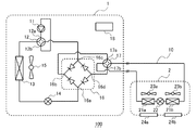
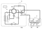
- FIG. 1 is a refrigerant circuit diagram showing the configuration of the refrigeration cycle device 100 according to the first embodiment.
- the refrigeration cycle device 100 according to the present embodiment is an air conditioner.
- the refrigeration cycle device 100 has an outdoor unit 1 installed outside the air-conditioned space and an indoor unit 2 installed inside the air-conditioned space.
- the outdoor unit 1 includes a compressor 11, a first flow path switching valve 12, an outdoor heat exchanger 13, a first expansion valve 14, an outdoor fan 15, a check valve bridge circuit 16, and a second flow path.
- a switching valve 17 and a control device 18 are provided.
- the indoor unit 2 includes a first indoor heat exchanger 21a, a second indoor heat exchanger 21b, a second expansion valve 22, a first indoor fan 23a, a second indoor fan 23b, and a first outlet 24a.
- a second outlet 24b is provided.
- the valve 22 and the second chamber heat exchanger 21b are connected by pipes to form a refrigerant circuit 10.
- the compressor 11 is a fluid machine that sucks in a low-pressure gas refrigerant, compresses it, and discharges it as a high-pressure gas refrigerant.
- the operating frequency of the compressor 11 is controlled by the control device 18.
- the first flow path switching valve 12 is a four-way valve that switches between a heating operation in which the outdoor heat exchanger 13 functions as an evaporator and a cooling operation in which the outdoor heat exchanger 13 functions as a condenser.
- the first flow path switching valve 12 has a high pressure port 12a maintained at a high pressure in both the heating operation and the cooling operation, and a low pressure port 12b maintained at a low pressure in both the heating operation and the cooling operation.
- the high pressure port 12a is connected to the discharge port of the compressor 11, and the low pressure port 12b is connected to the suction port of the compressor 11.
- the first flow path switching valve 12 is a check valve bridge circuit in which the control device 18 causes the refrigerant discharged from the compressor 11 to flow into the outdoor heat exchanger 13 and the refrigerant discharged from the compressor 11 to flow into the outdoor heat exchanger 13. It is switched to the second state in which the air flows into 16. That is, the first flow path switching valve 12 is set to the first state during the cooling operation and to the second state during the heating operation.
- the outdoor heat exchanger 13 is a heat exchanger that exchanges heat between the refrigerant circulating inside and the air blown by the outdoor fan 15.
- the outdoor heat exchanger 13 is arranged between the first flow path switching valve 12 and the first expansion valve 14 in the refrigerant circuit 10.
- the outdoor heat exchanger 13 functions as an evaporator during the heating operation and as a condenser during the cooling operation.
- the first expansion valve 14 is a valve that reduces the pressure of the refrigerant.
- an electronic expansion valve whose opening degree can be adjusted by the control of the control device 18 is used.
- the first expansion valve 14 is arranged between the outdoor heat exchanger 13 and the check valve bridge circuit 16 in the refrigerant circuit 10.
- the outdoor fan 15 supplies the air outside the air-conditioned space to the outdoor heat exchanger 13.
- the outdoor fan 15 is, for example, a propeller fan, a sirocco fan, or a cross-flow fan driven by a fan motor (not shown).
- the rotation speed of the outdoor fan 15 is controlled by the control device 18.
- the check valve bridge circuit 16 In the check valve bridge circuit 16, the refrigerant flowing between the check valve bridge circuit 16 and the second flow path switching valve 17 is in the first state and the second state of the first flow path switching valve 12. It is a rectifying unit that adjusts the flow of the refrigerant so that it flows in the same flow path.
- the check valve bridge circuit 16 is configured by arranging four check valves on a rectangular circuit that allow the flow of refrigerant in only one direction. As shown in FIG. 1, in the check valve bridge circuit 16, the check valves are arranged so that the flow directions of the refrigerants in the opposite flow paths are the same.
- the check valve bridge circuit 16 includes four ports 16a, 16b, 16c, 16d.
- the port 16a is connected to the first expansion valve 14, the port 16b is connected to the high voltage port 17a of the second flow path switching valve 17, the port 16c is connected to the first flow path switching valve 12, and the port 16d is connected. , Connected to the low voltage port 17b of the second flow path switching valve 17.
- the check valve bridge circuit 16 flows in from the high-pressure refrigerant that has flowed in from the port 16a when the first flow path switching valve 12 is in the first state, and from the port 16c when the first flow path switching valve 12 is in the second state.
- the high-pressure refrigerant is discharged from the port 16b.
- the check valve bridge circuit 16 receives the low-pressure refrigerant that has flowed into the port 16d from the low-pressure port 17b of the second flow path switching valve 17 from the port 16c when the first flow path switching valve 12 is in the first state. In the case of the second state, each is discharged from the port 16a.
- the check valve bridge circuit 16 allows the refrigerant flowing from the check valve bridge circuit 16 to the second flow path switching valve 17 in the first state and the second state of the first flow path switching valve 12. So, it can be flowed in the same flow path. Further, the check valve bridge circuit 16 allows the refrigerant flowing from the second flow path switching valve 17 to the check valve bridge circuit 16 depending on whether the first flow path switching valve 12 is in the first state or the second state. , Can flow in the same flow path.
- the second flow path switching valve 17 has the first chamber heat exchanger 21a or the second chamber heat exchanger 21b on the upstream side in the flow direction of the refrigerant flowing through the first chamber heat exchanger 21a and the second chamber heat exchanger 21b. It is a four-way valve that switches to.
- the second flow path switching valve 17 has a high pressure port 17a maintained at a high pressure in both the heating operation and the cooling operation, and a low pressure port 17b maintained at a low pressure in both the heating operation and the cooling operation.
- the high pressure port 17a of the second flow path switching valve 17 is connected to the port 16b of the check valve bridge circuit 16, and the low pressure port 17b is connected to the port 16d of the check valve bridge circuit 16.
- the second flow path switching valve 17 is switched by the control device 18 between the first state shown by the solid line in FIG. 1 and the second state shown by the broken line in FIG.
- the first state is a state in which the first chamber heat exchanger 21a is on the upstream side of the second chamber heat exchanger 21b in the flow direction of the refrigerant, and the first chamber heat exchanger 21a, the second expansion valve 22, Refrigerants flow in the order of the second chamber heat exchanger 21b.
- the second chamber heat exchanger 21b is on the upstream side of the first chamber heat exchanger 21a in the flow direction of the refrigerant, and the second chamber heat exchanger 21b and the second expansion valve
- the refrigerant flows in the order of 22 and the first chamber heat exchanger 21a.
- the control device 18 is a microcomputer provided with a CPU, ROM, RAM, an I / O port, and the like.
- the control device 18 controls the operation of the entire refrigeration cycle device 100, and executes the heating operation and the cooling operation. Specifically, the control device 18 controls the operating frequency of the compressor 11, the opening degree of the first expansion valve 14 and the second expansion valve 22, and the switching of the first flow path switching valve 12 and the second flow path switching valve 17. In addition, the rotation speeds of the outdoor fan 15, the first indoor fan 23a, and the second indoor fan 23b are controlled.
- the control device 18 may be provided not in the outdoor unit 1 but in the indoor unit 2, or the outdoor unit 1 and the indoor unit 2 may be provided with individual control devices 18 to communicate with each other.
- the first chamber heat exchanger 21a is a heat exchanger that exchanges heat between the refrigerant circulating inside and the air blown by the first chamber fan 23a.
- the first chamber heat exchanger 21a is arranged between the second flow path switching valve 17 and the second expansion valve 22 in the refrigerant circuit 10.
- the second chamber heat exchanger 21b is a heat exchanger that exchanges heat between the refrigerant circulating inside and the air blown by the second chamber fan 23b.
- the second chamber heat exchanger 21b is arranged between the second expansion valve 22 and the second flow path switching valve 17 in the refrigerant circuit 10.
- the first chamber heat exchanger 21a and the second chamber heat exchanger 21b function as a condenser during the heating operation and as an evaporator during the cooling operation.
- the heat exchange capacities of the first chamber heat exchanger 21a and the second chamber heat exchanger 21b may be the same or different.
- the first chamber heat exchanger 21a and the second chamber heat exchanger 21b are connected in series. Further, the number of indoor heat exchangers is not limited to two, and may be three or more.
- the second expansion valve 22 is a valve that reduces the pressure of the refrigerant.
- an electronic expansion valve whose opening degree can be adjusted by the control of the control device 18 is used.
- the second expansion valve 22 is arranged between the first chamber heat exchanger 21a and the second chamber heat exchanger 21b in the refrigerant circuit 10.
- the first indoor fan 23a supplies the air in the air-conditioned space to the first indoor heat exchanger 21a
- the second indoor fan 23b supplies the air in the air-conditioned space to the second indoor heat exchanger 21b.
- the first chamber fan 23a and the second chamber fan 23b are, for example, a propeller fan sirocco fan or a cross flow fan driven by a fan motor (not shown).
- the rotation speeds of the first chamber fan 23a and the second chamber fan 23b are controlled by the control device 18.
- the first outlet 24a and the second outlet 24b are openings provided in the housing of the indoor unit 2.
- the air heat-exchanged by the first chamber heat exchanger 21a is blown into the room from the first outlet 24a, and the air heat-exchanged by the second chamber heat exchanger 21b is blown out from the second outlet 24b.
- the first outlet 24a and the second outlet 24b may be provided independently of each other, or may be formed by dividing one opening by a wind direction plate.
- the refrigeration cycle device 100 may further include a temperature sensor or a pressure sensor (not shown).
- the refrigeration cycle device 100 includes an outside air temperature sensor that detects the temperature around the outdoor unit 1, an indoor temperature sensor that detects the temperature of the air-conditioning target space, a heat exchange temperature sensor that detects the temperature of each heat exchanger, and the like. You may.
- the refrigeration cycle device 100 may include an infrared sensor or an image sensor that detects the presence / absence of a person, the position of the person, and the body temperature of the person in the air-conditioned space. The detection results of these sensors are transmitted to the control device 18 and used for the operation control of the refrigeration cycle device 100.
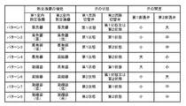
- FIG. 2 is a table showing a list of operation patterns of the refrigeration cycle apparatus 100 according to the first embodiment.
- the refrigeration cycle device 100 of the present embodiment can execute eight operation patterns.
- the operation pattern is selected and executed by the control device 18 according to the temperature of the air-conditioned space, the position and body temperature of a person in the air-conditioned space, or the setting by the user.
- the control device 18 controls the first flow path switching valve 12, the first expansion valve 14, the second flow path switching valve 17, and the second expansion valve 22 according to the operation pattern to be executed.
- Pattern 1 In pattern 1, both the first chamber heat exchanger 21a and the second chamber heat exchanger 21b function as evaporators, and the evaporation temperature of the first chamber heat exchanger 21a and the evaporation temperature of the second chamber heat exchanger 21b are set. The operation is the same. As a result, during the operation of pattern 1, a cooling operation is performed, and cold air having the same temperature is blown out from the first outlet 24a and the second outlet 24b.
- the temperature when the temperature is expressed as "same", it includes not only the case where the temperature is the same but also the case where the temperature is substantially the same (for example, when there is no difference in experience).
- the control device 18 sets the first flow path switching valve 12 to the first state. Further, in the case of pattern 1, since the evaporation temperature of the first chamber heat exchanger 21a and the evaporation temperature of the second chamber heat exchanger 21b are the same, the first chamber heat exchanger 21a and the second chamber heat exchanger 21a Either of 21b may be on the upstream side. Therefore, the control device 18 may set the second flow path switching valve 17 to either the first state or the second state. Hereinafter, the case where the second flow path switching valve 17 is set to the first state will be described. Further, the control device 18 sets the first expansion valve 14 in the open state and sets the opening degree to “small”.
- control device 18 sets the second expansion valve 22 in the open state and sets the opening degree to “large”.
- the control device 18 controls the opening degree of the first expansion valve 14 according to the cooling load or the heating load, and passes through the first expansion valve 14.
- the refrigerant is depressurized to become a low-pressure gas-liquid two-phase refrigerant.
- the control device 18 fully opens the opening degree of the second expansion valve 22, and the refrigerant passing through the second expansion valve 22 is hardly depressurized.
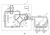
- FIG. 3 is a diagram showing the flow of the refrigerant when the refrigeration cycle device 100 according to the first embodiment performs the operation of the pattern 1.
- the refrigerant discharged from the compressor 11 flows into the outdoor heat exchanger 13 via the first flow path switching valve 12.
- the outdoor heat exchanger 13 functions as a condenser, and the heat of condensation of the refrigerant heat exchanged by the outdoor heat exchanger 13 is dissipated to the outside air.
- the refrigerant flowing out of the outdoor heat exchanger 13 flows into the first expansion valve 14.
- the refrigerant that has flowed into the first expansion valve 14 is depressurized and flows into the port 16a of the check valve bridge circuit 16.
- the refrigerant that has flowed into the port 16a of the check valve bridge circuit 16 flows out of the port 16b through the check valve and flows into the high-pressure port 17a of the second flow path switching valve 17.
- the refrigerant that has flowed into the high-pressure port 17a of the second flow path switching valve 17 flows into the first chamber heat exchanger 21a.
- the first chamber heat exchanger 21a functions as an evaporator, and air cooled by endothermic heat from the refrigerant is blown out from the first outlet 24a.
- the refrigerant flowing out of the first chamber heat exchanger 21a flows into the second expansion valve 22.
- the refrigerant that has flowed into the second expansion valve 22 flows into the second chamber heat exchanger 21b without being depressurized.
- the second chamber heat exchanger 21b functions as an evaporator, and air cooled by endothermic heat from the refrigerant is blown out from the second outlet 24b.
- the refrigerant flowing out of the second chamber heat exchanger 21b flows into the second flow path switching valve 17, and flows from the low pressure port 17b into the port 16d of the check valve bridge circuit 16.
- the refrigerant that has flowed into the port 16d of the check valve bridge circuit 16 flows out of the port 16c through the check valve and flows into the first flow path switching valve 12.
- the refrigerant that has flowed into the first flow path switching valve 12 flows out from the low pressure port 12b and is sucked into the compressor 11.
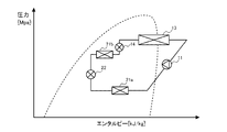
- FIG. 4 is a ph diagram when the refrigeration cycle device 100 according to the first embodiment operates in pattern 1.
- the high-pressure gas refrigerant discharged from the compressor 11 is condensed by the outdoor heat exchanger 13 to become a high-pressure liquid refrigerant.
- the high-pressure liquid refrigerant is depressurized by the first expansion valve 14, and becomes a low-pressure two-phase refrigerant.
- the low-pressure two-phase refrigerant is evaporated in the first chamber heat exchanger 21a and passes through the second expansion valve 22.
- the opening degree of the second expansion valve 22 is set to “large”, the refrigerant passing through the second expansion valve 22 is hardly depressurized.
- the low-pressure two-phase refrigerant that has passed through the second expansion valve 22 is evaporated by the second chamber heat exchanger 21b to become a low-pressure gas refrigerant. After that, the low-pressure gas refrigerant is sucked into the compressor 11, and one cycle ends.
- both the first chamber heat exchanger 21a and the second chamber heat exchanger 21b function as evaporators, and the evaporation temperature of the first chamber heat exchanger 21a is higher than the evaporation temperature of the second chamber heat exchanger 21b. Is also an expensive operation. As a result, during the operation of the pattern 2, the cooling operation is performed, and the temperature of the cold air blown out from the first outlet 24a becomes higher than the temperature of the cold air blown out from the second outlet 24b.
- the control device 18 sets the first flow path switching valve 12 to the first state. Further, the control device 18 sets the second flow path switching valve 17 to the first state so that the first chamber heat exchanger 21a is on the upstream side. Further, the control device 18 sets the first expansion valve 14 in the open state and sets the opening degree to “small”. Further, the control device 18 sets the second expansion valve 22 in the open state and sets the opening degree to “medium”. When the opening degree of the second expansion valve 22 is “medium”, the control device 18 uses the second expansion valve according to the target temperature difference between the first chamber heat exchanger 21a and the second chamber heat exchanger 21b. The opening degree of 22 is controlled.
- the control device 18 may control the opening degree of the second expansion valve 22 in consideration of the pressure loss in the check valve bridge circuit 16.
- FIG. 5 is a ph diagram when the refrigeration cycle device 100 according to the first embodiment performs the operation of the pattern 2.
- the high-pressure gas refrigerant discharged from the compressor 11 is condensed by the outdoor heat exchanger 13 to become a high-pressure liquid refrigerant.
- the high-pressure liquid refrigerant is depressurized by the first expansion valve 14, and becomes a low-pressure two-phase refrigerant.
- the low-pressure two-phase refrigerant is evaporated in the first chamber heat exchanger 21a and passes through the second expansion valve 22.
- the evaporation temperature of the first chamber heat exchanger 21a on the upstream side becomes higher than the evaporation temperature of the second chamber heat exchanger 21b.
- Cold air having a temperature higher than that of the second outlet 24b is blown out from the first outlet 24a.
- the air-conditioned space in which the indoor unit 2 is installed can be cooled at different temperatures, and air having an appropriate temperature can be sent to each user according to how the user feels the temperature.
- both the first chamber heat exchanger 21a and the second chamber heat exchanger 21b function as evaporators, and the evaporation temperature of the first chamber heat exchanger 21a is higher than the evaporation temperature of the second chamber heat exchanger 21b. Is also a low operation. As a result, during the operation of the pattern 3, the cooling operation is performed, and the temperature of the cold air blown out from the first outlet 24a becomes lower than the temperature of the cold air blown out from the second outlet 24b.
- the control device 18 sets the first flow path switching valve 12 to the first state. Further, the control device 18 sets the second flow path switching valve 17 to the second state so that the second chamber heat exchanger 21b is on the upstream side. Further, the control device 18 sets the first expansion valve 14 in the open state and sets the opening degree to “small”. Further, the control device 18 sets the second expansion valve 22 in the open state and sets the opening degree to “medium”.
- FIG. 6 is a diagram showing the flow of the refrigerant when the refrigeration cycle device 100 according to the first embodiment performs the operation of the pattern 3.
- the refrigerant discharged from the compressor 11 flows into the outdoor heat exchanger 13 via the first flow path switching valve 12.
- the outdoor heat exchanger 13 functions as a condenser, and the heat of condensation of the refrigerant heat exchanged by the outdoor heat exchanger 13 is dissipated to the outside air.
- the refrigerant flowing out of the outdoor heat exchanger 13 flows into the first expansion valve 14.
- the refrigerant that has flowed into the first expansion valve 14 is depressurized and flows into the port 16a of the check valve bridge circuit 16.
- the refrigerant that has flowed into the port 16a of the check valve bridge circuit 16 flows out of the port 16b through the check valve and flows into the high-pressure port 17a of the second flow path switching valve 17.
- the refrigerant that has flowed into the high-pressure port 17a of the second flow path switching valve 17 flows into the second chamber heat exchanger 21b.
- the second chamber heat exchanger 21b functions as an evaporator, and air cooled by endothermic heat from the refrigerant is blown out from the second outlet 24b.
- the refrigerant flowing out of the second chamber heat exchanger 21b flows into the second expansion valve 22.
- the refrigerant that has flowed into the second expansion valve 22 is depressurized and flows into the first chamber heat exchanger 21a.
- the first chamber heat exchanger 21a functions as an evaporator, and air cooled by endothermic heat from the refrigerant is blown out from the first outlet 24a.
- the refrigerant flowing out of the first chamber heat exchanger 21a flows into the second flow path switching valve 17, and flows from the low-pressure port 17b into the port 16d of the check valve bridge circuit 16.
- the refrigerant that has flowed into the port 16d of the check valve bridge circuit 16 flows out of the port 16c through the check valve and flows into the first flow path switching valve 12.
- the refrigerant that has flowed into the first flow path switching valve 12 flows out from the low pressure port 12b and is sucked into the compressor 11.
- the ph diagram when the refrigeration cycle device 100 performs the operation of pattern 3 is a diagram in which the first chamber heat exchanger 21a and the second chamber heat exchanger 21b in FIG. 5 are interchanged.
- the low-pressure two-phase refrigerant decompressed by the first expansion valve 14 first evaporates in the second chamber heat exchanger 21b, and is decompressed by the second expansion valve 22.
- the low-pressure two-phase refrigerant decompressed by the second expansion valve 22 evaporates in the first chamber heat exchanger 21a to become a low-pressure gas refrigerant.
- the evaporation temperature of the second chamber heat exchanger 21b on the upstream side becomes higher than the evaporation temperature of the first chamber heat exchanger 21a.
- Cold air having a temperature higher than that of the first outlet 24a is blown out from the second outlet 24b.
- the air-conditioned space in which the indoor unit 2 is installed can be cooled at different temperatures, and air having an appropriate temperature can be sent to each user according to how the user feels the temperature.
- Pattern 4 is an operation in which the first chamber heat exchanger 21a functions as an evaporator and the second chamber heat exchanger 21b functions as a condenser. As a result, during the operation of the pattern 4, simultaneous cooling and heating operation is performed, cold air is blown out from the first outlet 24a, and warm air is blown out from the second outlet 24b.
- the control device 18 sets the first flow path switching valve 12 to the first state. Further, the control device 18 sets the second flow path switching valve 17 to the second state so that the second chamber heat exchanger 21b is on the upstream side. Further, the control device 18 sets the first expansion valve 14 in the open state and sets the opening degree to “large”. Further, the control device 18 sets the second expansion valve 22 in the open state and sets the opening degree to “small”. When the opening degree of the first expansion valve 14 is "large”, the control device 18 of the first expansion valve 14 depends on the heating load of the first chamber heat exchanger 21a or the second chamber heat exchanger 21b. Control the opening.
- the control device 18 controls the opening degree of the second expansion valve 22 according to the cooling load, and the refrigerant passing through the second expansion valve 22 is released. The pressure is reduced so that it becomes a low-pressure gas-liquid two-phase refrigerant.
- FIG. 7 is a ph diagram when the refrigerating cycle device 100 according to the first embodiment performs the operation of the pattern 4.
- the high-pressure gas refrigerant discharged from the compressor 11 is condensed by the outdoor heat exchanger 13 to become a high-pressure two-phase refrigerant and flows into the first expansion valve 14.
- the refrigerant flowing into the first expansion valve 14 is depressurized by the first expansion valve 14 and condensed by the second chamber heat exchanger 21b.
- the high-pressure two-phase refrigerant condensed by the second chamber heat exchanger 21b is depressurized by the second expansion valve 22 to become a low-pressure two-phase refrigerant.
- the low-pressure two-phase refrigerant decompressed by the second expansion valve 22 is evaporated by the first chamber heat exchanger 21a to become a low-pressure gas refrigerant. After that, the low-pressure gas refrigerant is sucked into the compressor 11, and one cycle ends.
- the cold air cooled by the first chamber heat exchanger 21a functioning as an evaporator was blown out from the first outlet 24a and heated by the second chamber heat exchanger 21b functioning as a condenser. Warm air is blown out from the second outlet 24b.
- the air-conditioned space can be cooled and heated, and air having an appropriate temperature can be sent to each user according to how the user feels the temperature.
- Pattern 5 is an operation in which the first chamber heat exchanger 21a functions as a condenser and the second chamber heat exchanger 21b functions as an evaporator. As a result, during the operation of pattern 5, simultaneous cooling and heating operation is performed, warm air is blown out from the first outlet 24a, and cold air is blown out from the second outlet 24b.
- the control device 18 sets the first flow path switching valve 12 to the first state. Further, the control device 18 sets the second flow path switching valve 17 to the first state so that the first chamber heat exchanger 21a is on the upstream side. Further, the control device 18 sets the first expansion valve 14 in the open state and sets the opening degree to “large”. Further, the control device 18 sets the second expansion valve 22 in the open state and sets the opening degree to “small”.
- the flow of the refrigerant when the refrigeration cycle device 100 performs the operation of the pattern 4 is the same as the flow of the refrigerant when the operation of the pattern 1 shown in FIG. 3 is performed.
- the ph diagram when the refrigeration cycle apparatus 100 operates the pattern 5 shows that the first chamber heat exchanger 21a and the second chamber heat exchanger 21b in FIG. 7 are interchanged.
- the high-pressure two-phase refrigerant decompressed by the first expansion valve 14 is condensed by the first chamber heat exchanger 21a.
- the high-pressure two-phase refrigerant condensed by the first chamber heat exchanger 21a is depressurized by the second expansion valve 22 to become a low-pressure two-phase refrigerant.
- the low-pressure two-phase refrigerant decompressed by the second expansion valve 22 is evaporated by the second chamber heat exchanger 21b to become a low-pressure gas refrigerant. After that, the low-pressure gas refrigerant is sucked into the compressor 11, and one cycle ends.
- the warm air heated by the first chamber heat exchanger 21a functioning as a condenser was blown out from the first outlet 24a and cooled by the second chamber heat exchanger 21b functioning as an evaporator.
- Cold air is blown out from the second outlet 24b.
- the air-conditioned space can be cooled and heated, and air having an appropriate temperature can be sent to each user according to how the user feels the temperature.
- both the first chamber heat exchanger 21a and the second chamber heat exchanger 21b function as condensers, and the condensation temperature of the first chamber heat exchanger 21a and the condensation temperature of the second chamber heat exchanger 21b are set. The operation is the same. As a result, during the operation of the pattern 6, a heating operation is performed, and warm air having the same temperature is blown out from the first outlet 24a and the second outlet 24b.
- the control device 18 sets the first flow path switching valve 12 to the second state. Further, in the case of pattern 6, since the condensation temperature of the first chamber heat exchanger 21a and the condensation temperature of the second chamber heat exchanger 21b are the same, the first chamber heat exchanger 21a and the second chamber heat exchanger 21a Either of 21b may be on the upstream side. Therefore, the control device 18 may set the second flow path switching valve 17 to either the first state or the second state. Hereinafter, the case where the second flow path switching valve 17 is set to the first state will be described. Further, the control device 18 sets the first expansion valve 14 in the open state and sets the opening degree to “small”. Further, the control device 18 sets the second expansion valve 22 in the open state and sets the opening degree to “large”.
- FIG. 8 is a diagram showing the flow of the refrigerant when the refrigeration cycle device 100 according to the first embodiment performs the operation of the pattern 6.
- the refrigerant discharged from the compressor 11 flows into the port 16c of the check valve bridge circuit 16 via the first flow path switching valve 12.
- the refrigerant that has flowed into the port 16c of the check valve bridge circuit 16 flows out of the port 16b through the check valve and flows into the high-pressure port 17a of the second flow path switching valve 17.
- the refrigerant that has flowed into the high-pressure port 17a of the second flow path switching valve 17 flows into the first chamber heat exchanger 21a.
- the first chamber heat exchanger 21a functions as a condenser, and air heated by heat dissipation from the refrigerant is blown out from the first outlet 24a.
- the refrigerant flowing out of the first chamber heat exchanger 21a flows into the second expansion valve 22.
- the refrigerant that has flowed into the second expansion valve 22 flows into the second chamber heat exchanger 21b without being depressurized.
- the second chamber heat exchanger 21b functions as a condenser, and air heated by heat dissipation from the refrigerant is blown out from the second outlet 24b.
- the refrigerant flowing out of the second chamber heat exchanger 21b flows into the second flow path switching valve 17, and flows from the low pressure port 17b into the port 16d of the check valve bridge circuit 16.
- the refrigerant that has flowed into the port 16d of the check valve bridge circuit 16 flows out of the port 16a through the check valve and flows into the first expansion valve 14.
- the refrigerant that has flowed into the first expansion valve 14 is depressurized and flows into the outdoor heat exchanger 13.
- the outdoor heat exchanger 13 functions as an evaporator, and the heat of vaporization of the refrigerant is endothermic from the outdoor air.
- the refrigerant flowing out of the outdoor heat exchanger 13 is sucked into the compressor 11 through the first flow path switching valve 12.
- FIG. 9 is a ph diagram when the refrigeration cycle device 100 according to the first embodiment operates the pattern 6.
- the high-pressure gas refrigerant discharged from the compressor 11 is condensed by the first chamber heat exchanger 21a to become a high-pressure two-phase refrigerant.
- the opening degree of the second expansion valve 22 is set to “large”, the high-pressure two-phase refrigerant condensed by the first chamber heat exchanger 21a is hardly depressurized and is second. It passes through the expansion valve 22.
- the high-pressure two-phase refrigerant that has passed through the second expansion valve 22 is condensed by the second chamber heat exchanger 21b to become a high-pressure liquid refrigerant.
- the high-pressure liquid refrigerant is decompressed by the first expansion valve 14, and becomes a low-pressure two-phase refrigerant.
- the low-pressure two-phase refrigerant is evaporated by the outdoor heat exchanger 13 to become a low-pressure gas refrigerant. After that, the low-pressure gas refrigerant is sucked into the compressor 11 to end one cycle.
- both the first chamber heat exchanger 21a and the second chamber heat exchanger 21b function as condensers, and the condensation temperature of the first chamber heat exchanger 21a is higher than the condensation temperature of the second chamber heat exchanger 21b. Is also an expensive operation. As a result, during the operation of the pattern 7, the heating operation is performed, and the temperature of the warm air blown out from the first outlet 24a becomes higher than the temperature of the warm air blown out from the second outlet 24b.
- the control device 18 sets the first flow path switching valve 12 to the second state. Further, the control device 18 sets the second flow path switching valve 17 to the first state so that the first chamber heat exchanger 21a is on the upstream side. Further, the control device 18 sets the first expansion valve 14 in the open state and sets the opening degree to “small”. Further, the control device 18 sets the second expansion valve 22 in the open state and sets the opening degree to “medium”.
- FIG. 10 is a ph diagram when the refrigerating cycle device 100 according to the first embodiment performs the operation of the pattern 7.
- the high-pressure gas refrigerant discharged from the compressor 11 is condensed by the first chamber heat exchanger 21a to become a high-pressure two-phase refrigerant.
- the pressure is reduced by the second expansion valve 22.
- the two-phase refrigerant decompressed by the second expansion valve 22 is condensed by the second chamber heat exchanger 21b to become a high-pressure liquid refrigerant.
- the high-pressure liquid refrigerant flowing out of the second chamber heat exchanger 21b is depressurized by the first expansion valve 14 to become a low-pressure two-phase refrigerant.
- the low-pressure two-phase refrigerant is evaporated by the outdoor heat exchanger 13 to become a low-pressure gas refrigerant. After that, the low-pressure gas refrigerant returns to the compressor 11 and ends one cycle.
- the condensation temperature of the first chamber heat exchanger 21a on the upstream side becomes higher than the condensation temperature of the second chamber heat exchanger 21b.
- Warm air having a temperature higher than that of the second outlet 24b is blown out from the first outlet 24a.
- the air-conditioned space in which the indoor unit 2 is installed can be heated at different temperatures, and air having an appropriate temperature can be sent to each user according to how the user feels the temperature.
- both the first chamber heat exchanger 21a and the second chamber heat exchanger 21b function as condensers, and the condensation temperature of the first chamber heat exchanger 21a is higher than the condensation temperature of the second chamber heat exchanger 21b. Is also a low operation. As a result, during the operation of the pattern 8, the heating operation is performed, and the temperature of the warm air blown out from the first outlet 24a becomes lower than the temperature of the warm air blown out from the second outlet 24b.
- the control device 18 sets the first flow path switching valve 12 to the second state. Further, the control device 18 sets the second flow path switching valve 17 to the second state so that the second chamber heat exchanger 21b is on the upstream side. Further, the control device 18 sets the first expansion valve 14 in the open state and sets the opening degree to “small”. Further, the control device 18 sets the second expansion valve 22 in the open state and sets the opening degree to “medium”.
- FIG. 11 is a diagram showing the flow of the refrigerant when the refrigeration cycle device 100 according to the first embodiment operates in the pattern 8.
- the refrigerant discharged from the compressor 11 flows into the port 16c of the check valve bridge circuit 16 via the first flow path switching valve 12.
- the refrigerant that has flowed into the port 16c of the check valve bridge circuit 16 flows out of the port 16b through the check valve and flows into the high-pressure port 17a of the second flow path switching valve 17.
- the refrigerant that has flowed into the high-pressure port 17a of the second flow path switching valve 17 flows into the second chamber heat exchanger 21b.
- the second chamber heat exchanger 21b functions as a condenser, and air heated by heat dissipation from the refrigerant is blown out from the second outlet 24b.
- the refrigerant flowing out of the second chamber heat exchanger 21b flows into the second expansion valve 22.
- the refrigerant that has flowed into the second expansion valve 22 is depressurized and flows into the first chamber heat exchanger 21a.
- the first chamber heat exchanger 21a functions as a condenser, and air heated by heat dissipation from the refrigerant is blown out from the first outlet 24a.
- the refrigerant flowing out of the first chamber heat exchanger 21a flows into the second flow path switching valve 17, and flows from the low-pressure port 17b into the port 16d of the check valve bridge circuit 16.
- the refrigerant that has flowed into the port 16d of the check valve bridge circuit 16 flows out of the port 16a through the check valve and flows into the first expansion valve 14.
- the refrigerant that has flowed into the first expansion valve 14 is depressurized and flows into the outdoor heat exchanger 13.
- the outdoor heat exchanger 13 functions as an evaporator, and the heat of vaporization of the refrigerant is endothermic from the outdoor air.
- the refrigerant flowing out of the outdoor heat exchanger 13 is sucked into the compressor 11 via the first flow path switching valve 12.
- the ph diagram when the refrigeration cycle device 100 performs the operation of the pattern 8 shows that the first chamber heat exchanger 21a and the second chamber heat exchanger 21b in FIG. 10 are interchanged.
- the high-temperature gas refrigerant discharged from the compressor 11 is first condensed by the second chamber heat exchanger 21b and decompressed by the second expansion valve 22 to become a two-phase refrigerant.
- the two-phase refrigerant decompressed by the second expansion valve 22 is condensed by the first chamber heat exchanger 21a to become a high-pressure liquid refrigerant.
- the high-pressure liquid refrigerant is decompressed by the first expansion valve 14, and becomes a low-pressure two-phase refrigerant.
- the low-pressure two-phase refrigerant is heat-exchanged by the outdoor heat exchanger 13 that functions as an evaporator, and becomes a low-pressure gas refrigerant. After that, the low-pressure gas refrigerant is sucked into the compressor 11, and one cycle ends.
- the condensation temperature of the second chamber heat exchanger 21b on the upstream side becomes higher than the condensation temperature of the first chamber heat exchanger 21a.
- Warm air having a temperature higher than that of the first outlet 24a is blown out from the second outlet 24b.
- the air-conditioned space in which the indoor unit 2 is installed can be heated at different temperatures, and air having an appropriate temperature can be sent to each user according to how the user feels the temperature.
- the refrigerant flowing between the check valve bridge circuit 16 and the second flow path switching valve 17 can be any of the patterns 1 to 8.
- the flow flows in the same flow path.
- the high-pressure refrigerant flowing from the check valve bridge circuit 16 into the second flow path switching valve 17 is connected to the port 16b of the check valve bridge circuit 16. It flows through the flow path connecting the high pressure port 17a of the second flow path switching valve 17.
- the low-pressure refrigerant flowing from the second flow path switching valve 17 into the check valve bridge circuit 16 is opposite to the low-pressure port 17b of the second flow path switching valve 17.
- the first flow path switching valve 12 and the second flow path switching valve 17 can be configured by the same type of four-way valve, parts and software can be shared, and parts and software can be easily managed. Become.
- the flow path through which the high-pressure and high-temperature refrigerant flows and the flow path through which the low-pressure and low-temperature refrigerant flow are fixed to form a pipe through which the high-temperature refrigerant flows. It can be clearly distinguished from the piping through which low-temperature refrigerant flows. This facilitates the design of heat insulation around the pipe. Further, the pipe diameters of the pipe through which the high-pressure refrigerant flows and the pipe in which the low-pressure refrigerant flows can be designed so that the pressure loss is minimized.
- the pipe diameter of the pipe connecting the port 16d and the low pressure port 17b (the pipe through which the low pressure refrigerant flows) is set from the pipe diameter of the pipe connecting the port 16b and the high pressure port 17a (the pipe through which the high pressure refrigerant flows). Can also be made smaller. As a result, the pressure loss in the refrigerant circuit 10 can be reduced.
- Embodiment 2 Subsequently, the refrigeration cycle apparatus 100A according to the second embodiment will be described.
- the refrigeration cycle device 100A of the second embodiment is different from the first embodiment in the configuration of the rectifying unit.
- the same components as those in the first embodiment are designated by the same reference numerals, and the description thereof will be omitted.
- FIG. 12 is a refrigerant circuit diagram showing the configuration of the refrigeration cycle device 100A according to the second embodiment.
- the outdoor unit 1A of the refrigeration cycle device 100A according to the present embodiment is a hexagonal valve instead of the first flow path switching valve 12 and the check valve bridge circuit 16 of the first embodiment. It is equipped with 16A.
- the hexagonal valve 16A includes six ports a to f.
- the port a is connected to the discharge port of the compressor 11.
- the port b is connected to the outdoor heat exchanger 13.
- the port c is connected to the suction port of the compressor 11.
- the port d is connected to the low pressure port 17b of the second flow path switching valve 17.
- the port e is connected to the first expansion valve 14.
- the port f is connected to the high pressure port 17a of the second flow path switching valve 17.
- the hexagonal valve 16A has the function of the first flow path switching valve 12 in the first embodiment and the function of a rectifying unit including the check valve bridge circuit 16.
- the hexagonal valve 16A is switched between the first state and the second state by the control device 18.
- the port a and the port b are communicated with each other
- the port d and the port c are communicated with each other
- the port e and the port f are communicated with each other.
- the discharge port of the compressor 11 and the outdoor heat exchanger 13 are communicated with each other
- the suction port of the compressor 11 and the low pressure port 17b of the second flow path switching valve 17 are communicated with each other.
- the expansion valve 14 and the high pressure port 17a of the second flow path switching valve 17 are communicated with each other.
- the port a and the port f are communicated with each other, the port b and the port c are communicated with each other, and the port d and the port e are communicated with each other.
- the discharge port of the compressor 11 and the high-pressure port 17a of the second flow path switching valve 17 are communicated with each other, and the suction port of the compressor 11 and the outdoor heat exchanger 13 are communicated with each other.
- the low pressure port 17b of the flow path switching valve 17 and the first expansion valve 14 are communicated with each other. That is, the hexagonal valve 16A is set to the first state during the cooling operation and the second state during the heating operation.
- FIG. 13 is a table showing a list of operation patterns of the refrigeration cycle apparatus 100A according to the second embodiment.
- the refrigeration cycle apparatus 100A of the present embodiment can execute eight operation patterns. The operation pattern is selected and executed according to the temperature of the air-conditioned space, the position and body temperature of a person in the air-conditioned space, or the setting by the user.
- the control device 18 controls the hexagonal valve 16A, the first expansion valve 14, the second flow path switching valve 17, and the second expansion valve 22 according to the operation pattern to be executed.
- patterns 1 to 8 of the present embodiment are the same as the operations of patterns 1 to 8 of the first embodiment. Further, the functions of the first chamber heat exchanger 21a and the second chamber heat exchanger 21b during the operation of patterns 1 to 8 of the present embodiment, as well as the second flow path switching valve 17, the first expansion valve 14, and the second.
- the setting of the expansion valve 22 is the same as that of the first embodiment. In the following, the operation of the hexagonal valve 16A in each pattern will be mainly described.
- the control device 18 sets the hexagonal valve 16A to the first state when the patterns 1 to 5 are operating, and sets the hexagonal valve 16A to the second state when the patterns 6 to 7 are operating.
- FIG. 14 is a diagram showing the flow of the refrigerant in the refrigeration cycle device 100A according to the second embodiment.
- the solid line arrow in FIG. 14 indicates the flow of the refrigerant when the refrigeration cycle device 100A performs the operations of patterns 1 to 5, and the broken line arrow indicates the flow of the refrigerant when the refrigeration cycle device 100A performs the operations of patterns 6 to 8. Is shown. Since the flow of the refrigerant in each pattern in the indoor unit 2 is the same as that in the first embodiment, the illustration and description will be omitted.
- the refrigeration cycle device 100A When the refrigeration cycle device 100A operates the patterns 1 to 5, the refrigerant discharged from the compressor 11 flows into the outdoor heat exchanger 13 via the ports a and b of the hexagonal valve 16A.
- the outdoor heat exchanger 13 functions as a condenser, and the heat of condensation of the refrigerant is dissipated to the outside air.
- the refrigerant flowing out of the outdoor heat exchanger 13 flows into the first expansion valve 14.
- the refrigerant that has flowed into the first expansion valve 14 is depressurized and flows into port e of the hexagonal valve 16A.
- the refrigerant that has flowed into the port e of the hexagonal valve 16A flows from the port f of the hexagonal valve 16A into the high pressure port 17a of the second flow path switching valve 17.
- the refrigerant flows in the order of the first chamber heat exchanger 21a, the second expansion valve 22, and the second chamber heat exchanger 21b, and in the second state, the refrigerant flows in this order.
- Refrigerant flows in the order of the second chamber heat exchanger 21b, the second expansion valve 22, and the first chamber heat exchanger 21a.
- pattern 1 cold air having the same temperature is blown out from the first outlet 24a and the second outlet 24b, and in the case of pattern 2 and pattern 3, the first outlet 24a and the second outlet 24b. Cold air of different temperatures is blown out.
- the pattern 4 and the pattern 5 cold air and warm air are blown out from the first outlet 24a and the second outlet 24b.
- the refrigerant flowing out from the first chamber heat exchanger 21a or the second chamber heat exchanger 21b on the downstream side flows into the port d of the hexagonal valve 16A via the low pressure port 17b of the second flow path switching valve 17. Then, it is sucked into the compressor 11 from the port d of the hexagonal valve 16A via the port c.
- the refrigerating cycle device 100A operates the patterns 6 to 8
- the refrigerant discharged from the compressor 11 passes through the ports a and f of the hexagonal valve 16A and the high pressure port of the second flow path switching valve 17. It flows into 17a.
- the refrigerant flows in the order of the first chamber heat exchanger 21a, the second expansion valve 22, and the second chamber heat exchanger 21b, and in the second state, the refrigerant flows in this order.
- Refrigerant flows in the order of the second chamber heat exchanger 21b, the second expansion valve 22, and the first chamber heat exchanger 21a.
- the refrigerant that has flowed into the first expansion valve 14 is depressurized and flows into the outdoor heat exchanger 13.
- the outdoor heat exchanger 13 functions as an evaporator, and the heat of vaporization of the refrigerant is endothermic from the outdoor air.
- the refrigerant flowing out of the outdoor heat exchanger 13 flows into the port b of the hexagonal valve 16A. Then, the refrigerant that has flowed into the port b of the hexagonal valve 16A is sucked into the compressor 11 via the port c.
- the ph diagram when the refrigeration cycle device 100A of the present embodiment performs the operations of patterns 1 to 5 is the same as that of the first embodiment, and is shown in FIGS. 4, 5, and 7, respectively. Further, the ph diagram when the refrigeration cycle device 100A of the present embodiment performs the operations of patterns 6 to 8 is the same as that of the first embodiment, and is shown in FIGS. 9 and 10, respectively.
- the refrigerant flowing between the hexagonal valve 16A and the second flow path switching valve 17 performs any of the operations of patterns 1 to 8. Also flows in the same flow path. Specifically, in any of the operations of patterns 1 to 8, the high-pressure refrigerant flowing from the hexagonal valve 16A into the second flow path switching valve 17 is the port f of the hexagonal valve 16A and the second flow path switching valve. It flows through a flow path connecting the high-voltage port 17a of 17.
- the low-pressure refrigerant flowing into the hexagonal valve 16A from the second flow path switching valve 17 is the low-pressure port 17b and the hexagonal valve 16A of the second flow path switching valve 17. It flows through the flow path connecting to the port d.
- the high-pressure refrigerant flows into the high-pressure port 17a of the second flow path switching valve 17, and only the low-pressure refrigerant flows out from the low-pressure port 17b.
- the second flow path switching valve 17 a conventional four-way valve in which the high-pressure port and the low-pressure port are fixed can be used.
- the piping through which the high-temperature refrigerant flows and the piping through which the low-temperature refrigerant flows can be clearly distinguished, it is easy to design the heat insulation around the piping, and the piping between the piping through which the high-pressure refrigerant flows and the piping through which the low-pressure refrigerant flows The diameter can be designed to minimize pressure loss.
- the first flow path switching valve 12 of the first embodiment and the rectifying section including the check valve bridge circuit 16 are configured by the hexagonal valve 16A, so that the components are different from those of the first embodiment. Achieves reductions in points and costs.
- the rectifying unit is not limited to the check valve bridge circuit 16 or the hexagonal valve 16A, and may be composed of a combination of a plurality of other valves.
- the first chamber fan 23a and the second chamber fan 23b corresponding to the first chamber heat exchanger 21a and the second chamber heat exchanger 21b are provided, respectively, but the configuration is limited to this. It's not a thing.
- it may be configured to include one indoor fan corresponding to the first indoor heat exchanger 21a and the second indoor heat exchanger 21b.
- the rectifying unit including the check valve bridge circuit 16 or the hexagonal valve 16A and the second flow path switching valve 17 are provided in the outdoor unit 1 or the outdoor unit 1A, but the present invention is limited to this. It is not something that is done.
- at least one of the rectifying unit and the second flow path switching valve 17 may be provided in the indoor unit 2.
- the space of the indoor unit 2 can be maximized, and the performance deterioration due to the pressure loss of the indoor heat exchanger is small. Further, there are effects such that the differential pressure in the second flow path switching valve 17 can be easily secured.
- the refrigeration cycle device 100 is an air conditioner used for air conditioning
- the refrigeration cycle device 100 includes a hot water supply device, a refrigerator, and the like. It may be a refrigerator, a heat pump chiller, or the like.
Landscapes
- Engineering & Computer Science (AREA)
- Physics & Mathematics (AREA)
- Mechanical Engineering (AREA)
- Thermal Sciences (AREA)
- General Engineering & Computer Science (AREA)
- Air Conditioning Control Device (AREA)
Abstract
La présente invention concerne un dispositif à cycle de réfrigération comprenant un compresseur, une première vanne de commutation de trajet d'écoulement raccordée au compresseur, un échangeur de chaleur extérieur raccordé à la première vanne de commutation de trajet d'écoulement, une première vanne de détente raccordée à l'échangeur de chaleur extérieur, un stabilisateur d'écoulement raccordé à la première vanne de détente, une deuxième vanne de commutation de trajet d'écoulement raccordée au stabilisateur d'écoulement, des premier et deuxième échangeurs de chaleur intérieurs raccordés en série à la deuxième vanne de commutation de trajet d'écoulement, et une deuxième vanne de détente située entre les premier et deuxième échangeurs de chaleur intérieurs, la première vanne de commutation de trajet d'écoulement étant commutée entre un premier état dans lequel le fluide frigorigène évacué depuis le compresseur s'écoule dans l'échangeur de chaleur extérieur et un deuxième état dans lequel le fluide frigorigène évacué depuis le compresseur s'écoule dans le stabilisateur d'écoulement, et le stabilisateur d'écoulement permet au fluide frigorigène s'écoulant depuis le stabilisateur d'écoulement vers la deuxième vanne de commutation de trajet d'écoulement de s'écouler dans le même trajet d'écoulement à la fois lorsque la première vanne de commutation de trajet d'écoulement est dans le premier état et dans le deuxième état, et permet à un fluide frigorigène s'écoulant depuis la deuxième vanne de commutation de trajet d'écoulement vers le stabilisateur d'écoulement de s'écouler dans le même trajet d'écoulement à la fois lorsque la première vanne de commutation de trajet d'écoulement est dans le premier état et dans le deuxième état.
Priority Applications (2)
| Application Number | Priority Date | Filing Date | Title |
|---|---|---|---|
| PCT/JP2019/036463 WO2021053740A1 (fr) | 2019-09-18 | 2019-09-18 | Dispositif à cycle de réfrigération |
| JP2021546096A JP7246501B2 (ja) | 2019-09-18 | 2019-09-18 | 冷凍サイクル装置 |
Applications Claiming Priority (1)
| Application Number | Priority Date | Filing Date | Title |
|---|---|---|---|
| PCT/JP2019/036463 WO2021053740A1 (fr) | 2019-09-18 | 2019-09-18 | Dispositif à cycle de réfrigération |
Publications (1)
| Publication Number | Publication Date |
|---|---|
| WO2021053740A1 true WO2021053740A1 (fr) | 2021-03-25 |
Family
ID=74884396
Family Applications (1)
| Application Number | Title | Priority Date | Filing Date |
|---|---|---|---|
| PCT/JP2019/036463 Ceased WO2021053740A1 (fr) | 2019-09-18 | 2019-09-18 | Dispositif à cycle de réfrigération |
Country Status (2)
| Country | Link |
|---|---|
| JP (1) | JP7246501B2 (fr) |
| WO (1) | WO2021053740A1 (fr) |
Citations (7)
| Publication number | Priority date | Publication date | Assignee | Title |
|---|---|---|---|---|
| JP2000161805A (ja) * | 1998-11-27 | 2000-06-16 | Daikin Ind Ltd | 冷凍装置 |
| JP2001317831A (ja) * | 2000-05-08 | 2001-11-16 | Matsushita Electric Ind Co Ltd | 空気調和機 |
| JP2003139429A (ja) * | 2001-10-30 | 2003-05-14 | Daikin Ind Ltd | 冷凍装置 |
| WO2013179334A1 (fr) * | 2012-05-30 | 2013-12-05 | 三菱電機株式会社 | Dispositif de conditionnement d'air |
| CN106440454A (zh) * | 2016-08-31 | 2017-02-22 | 珠海格力电器股份有限公司 | 空调系统及空调系统的控制方法 |
| US20170284684A1 (en) * | 2014-10-21 | 2017-10-05 | Gd Midea Heating & Ventilating Equipment Co., Ltd. | Multi-split air-conditioner and outdoor unit system thereof |
| US20170299202A1 (en) * | 2016-04-13 | 2017-10-19 | Trane International Inc. | Multi-functional heat pump apparatus |
-
2019
- 2019-09-18 WO PCT/JP2019/036463 patent/WO2021053740A1/fr not_active Ceased
- 2019-09-18 JP JP2021546096A patent/JP7246501B2/ja active Active
Patent Citations (7)
| Publication number | Priority date | Publication date | Assignee | Title |
|---|---|---|---|---|
| JP2000161805A (ja) * | 1998-11-27 | 2000-06-16 | Daikin Ind Ltd | 冷凍装置 |
| JP2001317831A (ja) * | 2000-05-08 | 2001-11-16 | Matsushita Electric Ind Co Ltd | 空気調和機 |
| JP2003139429A (ja) * | 2001-10-30 | 2003-05-14 | Daikin Ind Ltd | 冷凍装置 |
| WO2013179334A1 (fr) * | 2012-05-30 | 2013-12-05 | 三菱電機株式会社 | Dispositif de conditionnement d'air |
| US20170284684A1 (en) * | 2014-10-21 | 2017-10-05 | Gd Midea Heating & Ventilating Equipment Co., Ltd. | Multi-split air-conditioner and outdoor unit system thereof |
| US20170299202A1 (en) * | 2016-04-13 | 2017-10-19 | Trane International Inc. | Multi-functional heat pump apparatus |
| CN106440454A (zh) * | 2016-08-31 | 2017-02-22 | 珠海格力电器股份有限公司 | 空调系统及空调系统的控制方法 |
Also Published As
| Publication number | Publication date |
|---|---|
| JP7246501B2 (ja) | 2023-03-27 |
| JPWO2021053740A1 (fr) | 2021-03-25 |
Similar Documents
| Publication | Publication Date | Title |
|---|---|---|
| US20130213077A1 (en) | Multi-split air conditioner capable of refrigerating and heating simultaneously | |
| GB2569898A (en) | Air conditioner | |
| WO2018061188A1 (fr) | Unité intérieure et climatiseur | |
| US11499727B2 (en) | Air conditioning apparatus | |
| EP3492839A1 (fr) | Dispositif à cycle de réfrigération | |
| JP2019109044A (ja) | 室内機 | |
| JP2017101855A (ja) | 空気調和装置 | |
| US11578898B2 (en) | Air conditioning apparatus | |
| WO2014132433A1 (fr) | Dispositif de climatisation | |
| WO2015140994A1 (fr) | Unité côté source de chaleur et climatiseur | |
| JP6750240B2 (ja) | 空気調和装置 | |
| JP2016020784A (ja) | 空気調和装置 | |
| WO2021014520A1 (fr) | Dispositif de climatisation | |
| KR200469716Y1 (ko) | 공조시스템 | |
| KR102509997B1 (ko) | 실외 유닛 | |
| JP2002228187A (ja) | 空冷ヒートポンプ式外気処理空調機 | |
| JP2008157557A (ja) | 空気調和装置 | |
| EP3492844B1 (fr) | Climatiseur | |
| EP3715735B1 (fr) | Appareil de climatisation | |
| JP2022052743A (ja) | 冷暖房換気マルチ空気調和機 | |
| JP7246501B2 (ja) | 冷凍サイクル装置 | |
| JP7573733B2 (ja) | 冷凍サイクル装置 | |
| US11397015B2 (en) | Air conditioning apparatus | |
| KR20120049441A (ko) | 히트 펌프식 공기조화기 | |
| KR102436705B1 (ko) | 공기조화기 |
Legal Events
| Date | Code | Title | Description |
|---|---|---|---|
| ENP | Entry into the national phase |
Ref document number: 2021546096 Country of ref document: JP Kind code of ref document: A |
|
| NENP | Non-entry into the national phase |
Ref country code: DE |
|
| 122 | Ep: pct application non-entry in european phase |
Ref document number: 19945483 Country of ref document: EP Kind code of ref document: A1 |