WO2021054088A1 - 建設機械 - Google Patents
建設機械 Download PDFInfo
- Publication number
- WO2021054088A1 WO2021054088A1 PCT/JP2020/032712 JP2020032712W WO2021054088A1 WO 2021054088 A1 WO2021054088 A1 WO 2021054088A1 JP 2020032712 W JP2020032712 W JP 2020032712W WO 2021054088 A1 WO2021054088 A1 WO 2021054088A1
- Authority
- WO
- WIPO (PCT)
- Prior art keywords
- rotation speed
- pressure
- swivel
- target
- motor
- Prior art date
- Legal status (The legal status is an assumption and is not a legal conclusion. Google has not performed a legal analysis and makes no representation as to the accuracy of the status listed.)
- Ceased
Links
Images






Classifications
-
- E—FIXED CONSTRUCTIONS
- E02—HYDRAULIC ENGINEERING; FOUNDATIONS; SOIL SHIFTING
- E02F—DREDGING; SOIL-SHIFTING
- E02F9/00—Component parts of dredgers or soil-shifting machines, not restricted to one of the kinds covered by groups E02F3/00 - E02F7/00
- E02F9/20—Drives; Control devices
-
- E—FIXED CONSTRUCTIONS
- E02—HYDRAULIC ENGINEERING; FOUNDATIONS; SOIL SHIFTING
- E02F—DREDGING; SOIL-SHIFTING
- E02F9/00—Component parts of dredgers or soil-shifting machines, not restricted to one of the kinds covered by groups E02F3/00 - E02F7/00
- E02F9/20—Drives; Control devices
- E02F9/22—Hydraulic or pneumatic drives
- E02F9/2203—Arrangements for controlling the attitude of actuators, e.g. speed, floating function
-
- E—FIXED CONSTRUCTIONS
- E02—HYDRAULIC ENGINEERING; FOUNDATIONS; SOIL SHIFTING
- E02F—DREDGING; SOIL-SHIFTING
- E02F9/00—Component parts of dredgers or soil-shifting machines, not restricted to one of the kinds covered by groups E02F3/00 - E02F7/00
- E02F9/08—Superstructures; Supports for superstructures
- E02F9/10—Supports for movable superstructures mounted on travelling or walking gears or on other superstructures
- E02F9/12—Slewing or traversing gears
- E02F9/121—Turntables, i.e. structure rotatable about 360°
- E02F9/123—Drives or control devices specially adapted therefor
-
- E—FIXED CONSTRUCTIONS
- E02—HYDRAULIC ENGINEERING; FOUNDATIONS; SOIL SHIFTING
- E02F—DREDGING; SOIL-SHIFTING
- E02F9/00—Component parts of dredgers or soil-shifting machines, not restricted to one of the kinds covered by groups E02F3/00 - E02F7/00
- E02F9/20—Drives; Control devices
- E02F9/22—Hydraulic or pneumatic drives
-
- E—FIXED CONSTRUCTIONS
- E02—HYDRAULIC ENGINEERING; FOUNDATIONS; SOIL SHIFTING
- E02F—DREDGING; SOIL-SHIFTING
- E02F9/00—Component parts of dredgers or soil-shifting machines, not restricted to one of the kinds covered by groups E02F3/00 - E02F7/00
- E02F9/20—Drives; Control devices
- E02F9/22—Hydraulic or pneumatic drives
- E02F9/2221—Control of flow rate; Load sensing arrangements
- E02F9/2232—Control of flow rate; Load sensing arrangements using one or more variable displacement pumps
- E02F9/2235—Control of flow rate; Load sensing arrangements using one or more variable displacement pumps including an electronic controller
-
- E—FIXED CONSTRUCTIONS
- E02—HYDRAULIC ENGINEERING; FOUNDATIONS; SOIL SHIFTING
- E02F—DREDGING; SOIL-SHIFTING
- E02F9/00—Component parts of dredgers or soil-shifting machines, not restricted to one of the kinds covered by groups E02F3/00 - E02F7/00
- E02F9/20—Drives; Control devices
- E02F9/22—Hydraulic or pneumatic drives
- E02F9/2278—Hydraulic circuits
- E02F9/2296—Systems with a variable displacement pump
-
- F—MECHANICAL ENGINEERING; LIGHTING; HEATING; WEAPONS; BLASTING
- F15—FLUID-PRESSURE ACTUATORS; HYDRAULICS OR PNEUMATICS IN GENERAL
- F15B—SYSTEMS ACTING BY MEANS OF FLUIDS IN GENERAL; FLUID-PRESSURE ACTUATORS, e.g. SERVOMOTORS; DETAILS OF FLUID-PRESSURE SYSTEMS, NOT OTHERWISE PROVIDED FOR
- F15B11/00—Servomotor systems without provision for follow-up action; Circuits therefor
- F15B11/02—Systems essentially incorporating special features for controlling the speed or actuating force of an output member
-
- F—MECHANICAL ENGINEERING; LIGHTING; HEATING; WEAPONS; BLASTING
- F15—FLUID-PRESSURE ACTUATORS; HYDRAULICS OR PNEUMATICS IN GENERAL
- F15B—SYSTEMS ACTING BY MEANS OF FLUIDS IN GENERAL; FLUID-PRESSURE ACTUATORS, e.g. SERVOMOTORS; DETAILS OF FLUID-PRESSURE SYSTEMS, NOT OTHERWISE PROVIDED FOR
- F15B11/00—Servomotor systems without provision for follow-up action; Circuits therefor
- F15B11/02—Systems essentially incorporating special features for controlling the speed or actuating force of an output member
- F15B11/028—Systems essentially incorporating special features for controlling the speed or actuating force of an output member for controlling the actuating force
-
- E—FIXED CONSTRUCTIONS
- E02—HYDRAULIC ENGINEERING; FOUNDATIONS; SOIL SHIFTING
- E02F—DREDGING; SOIL-SHIFTING
- E02F3/00—Dredgers; Soil-shifting machines
- E02F3/04—Dredgers; Soil-shifting machines mechanically-driven
- E02F3/28—Dredgers; Soil-shifting machines mechanically-driven with digging tools mounted on a dipper- or bucket-arm, i.e. there is either one arm or a pair of arms, e.g. dippers, buckets
- E02F3/36—Component parts
- E02F3/42—Drives for dippers, buckets, dipper-arms or bucket-arms
- E02F3/43—Control of dipper or bucket position; Control of sequence of drive operations
- E02F3/435—Control of dipper or bucket position; Control of sequence of drive operations for dipper-arms, backhoes or the like
-
- F—MECHANICAL ENGINEERING; LIGHTING; HEATING; WEAPONS; BLASTING
- F15—FLUID-PRESSURE ACTUATORS; HYDRAULICS OR PNEUMATICS IN GENERAL
- F15B—SYSTEMS ACTING BY MEANS OF FLUIDS IN GENERAL; FLUID-PRESSURE ACTUATORS, e.g. SERVOMOTORS; DETAILS OF FLUID-PRESSURE SYSTEMS, NOT OTHERWISE PROVIDED FOR
- F15B2211/00—Circuits for servomotor systems
- F15B2211/20—Fluid pressure source, e.g. accumulator or variable axial piston pump
- F15B2211/205—Systems with pumps
- F15B2211/2053—Type of pump
- F15B2211/20546—Type of pump variable capacity
-
- F—MECHANICAL ENGINEERING; LIGHTING; HEATING; WEAPONS; BLASTING
- F15—FLUID-PRESSURE ACTUATORS; HYDRAULICS OR PNEUMATICS IN GENERAL
- F15B—SYSTEMS ACTING BY MEANS OF FLUIDS IN GENERAL; FLUID-PRESSURE ACTUATORS, e.g. SERVOMOTORS; DETAILS OF FLUID-PRESSURE SYSTEMS, NOT OTHERWISE PROVIDED FOR
- F15B2211/00—Circuits for servomotor systems
- F15B2211/40—Flow control
- F15B2211/415—Flow control characterised by the connections of the flow control means in the circuit
- F15B2211/41563—Flow control characterised by the connections of the flow control means in the circuit being connected to a pressure source and a return line
-
- F—MECHANICAL ENGINEERING; LIGHTING; HEATING; WEAPONS; BLASTING
- F15—FLUID-PRESSURE ACTUATORS; HYDRAULICS OR PNEUMATICS IN GENERAL
- F15B—SYSTEMS ACTING BY MEANS OF FLUIDS IN GENERAL; FLUID-PRESSURE ACTUATORS, e.g. SERVOMOTORS; DETAILS OF FLUID-PRESSURE SYSTEMS, NOT OTHERWISE PROVIDED FOR
- F15B2211/00—Circuits for servomotor systems
- F15B2211/40—Flow control
- F15B2211/42—Flow control characterised by the type of actuation
- F15B2211/426—Flow control characterised by the type of actuation electrically or electronically
-
- F—MECHANICAL ENGINEERING; LIGHTING; HEATING; WEAPONS; BLASTING
- F15—FLUID-PRESSURE ACTUATORS; HYDRAULICS OR PNEUMATICS IN GENERAL
- F15B—SYSTEMS ACTING BY MEANS OF FLUIDS IN GENERAL; FLUID-PRESSURE ACTUATORS, e.g. SERVOMOTORS; DETAILS OF FLUID-PRESSURE SYSTEMS, NOT OTHERWISE PROVIDED FOR
- F15B2211/00—Circuits for servomotor systems
- F15B2211/40—Flow control
- F15B2211/45—Control of bleed-off flow, e.g. control of bypass flow to the return line
-
- F—MECHANICAL ENGINEERING; LIGHTING; HEATING; WEAPONS; BLASTING
- F15—FLUID-PRESSURE ACTUATORS; HYDRAULICS OR PNEUMATICS IN GENERAL
- F15B—SYSTEMS ACTING BY MEANS OF FLUIDS IN GENERAL; FLUID-PRESSURE ACTUATORS, e.g. SERVOMOTORS; DETAILS OF FLUID-PRESSURE SYSTEMS, NOT OTHERWISE PROVIDED FOR
- F15B2211/00—Circuits for servomotor systems
- F15B2211/50—Pressure control
- F15B2211/505—Pressure control characterised by the type of pressure control means
- F15B2211/50509—Pressure control characterised by the type of pressure control means the pressure control means controlling a pressure upstream of the pressure control means
- F15B2211/50536—Pressure control characterised by the type of pressure control means the pressure control means controlling a pressure upstream of the pressure control means using unloading valves controlling the supply pressure by diverting fluid to the return line
-
- F—MECHANICAL ENGINEERING; LIGHTING; HEATING; WEAPONS; BLASTING
- F15—FLUID-PRESSURE ACTUATORS; HYDRAULICS OR PNEUMATICS IN GENERAL
- F15B—SYSTEMS ACTING BY MEANS OF FLUIDS IN GENERAL; FLUID-PRESSURE ACTUATORS, e.g. SERVOMOTORS; DETAILS OF FLUID-PRESSURE SYSTEMS, NOT OTHERWISE PROVIDED FOR
- F15B2211/00—Circuits for servomotor systems
- F15B2211/50—Pressure control
- F15B2211/515—Pressure control characterised by the connections of the pressure control means in the circuit
- F15B2211/5157—Pressure control characterised by the connections of the pressure control means in the circuit being connected to a pressure source and a return line
-
- F—MECHANICAL ENGINEERING; LIGHTING; HEATING; WEAPONS; BLASTING
- F15—FLUID-PRESSURE ACTUATORS; HYDRAULICS OR PNEUMATICS IN GENERAL
- F15B—SYSTEMS ACTING BY MEANS OF FLUIDS IN GENERAL; FLUID-PRESSURE ACTUATORS, e.g. SERVOMOTORS; DETAILS OF FLUID-PRESSURE SYSTEMS, NOT OTHERWISE PROVIDED FOR
- F15B2211/00—Circuits for servomotor systems
- F15B2211/50—Pressure control
- F15B2211/52—Pressure control characterised by the type of actuation
- F15B2211/526—Pressure control characterised by the type of actuation electrically or electronically
-
- F—MECHANICAL ENGINEERING; LIGHTING; HEATING; WEAPONS; BLASTING
- F15—FLUID-PRESSURE ACTUATORS; HYDRAULICS OR PNEUMATICS IN GENERAL
- F15B—SYSTEMS ACTING BY MEANS OF FLUIDS IN GENERAL; FLUID-PRESSURE ACTUATORS, e.g. SERVOMOTORS; DETAILS OF FLUID-PRESSURE SYSTEMS, NOT OTHERWISE PROVIDED FOR
- F15B2211/00—Circuits for servomotor systems
- F15B2211/60—Circuit components or control therefor
- F15B2211/63—Electronic controllers
- F15B2211/6303—Electronic controllers using input signals
- F15B2211/6306—Electronic controllers using input signals representing a pressure
- F15B2211/6313—Electronic controllers using input signals representing a pressure the pressure being a load pressure
-
- F—MECHANICAL ENGINEERING; LIGHTING; HEATING; WEAPONS; BLASTING
- F15—FLUID-PRESSURE ACTUATORS; HYDRAULICS OR PNEUMATICS IN GENERAL
- F15B—SYSTEMS ACTING BY MEANS OF FLUIDS IN GENERAL; FLUID-PRESSURE ACTUATORS, e.g. SERVOMOTORS; DETAILS OF FLUID-PRESSURE SYSTEMS, NOT OTHERWISE PROVIDED FOR
- F15B2211/00—Circuits for servomotor systems
- F15B2211/60—Circuit components or control therefor
- F15B2211/63—Electronic controllers
- F15B2211/6303—Electronic controllers using input signals
- F15B2211/6336—Electronic controllers using input signals representing a state of the output member, e.g. position, speed or acceleration
-
- F—MECHANICAL ENGINEERING; LIGHTING; HEATING; WEAPONS; BLASTING
- F15—FLUID-PRESSURE ACTUATORS; HYDRAULICS OR PNEUMATICS IN GENERAL
- F15B—SYSTEMS ACTING BY MEANS OF FLUIDS IN GENERAL; FLUID-PRESSURE ACTUATORS, e.g. SERVOMOTORS; DETAILS OF FLUID-PRESSURE SYSTEMS, NOT OTHERWISE PROVIDED FOR
- F15B2211/00—Circuits for servomotor systems
- F15B2211/60—Circuit components or control therefor
- F15B2211/665—Methods of control using electronic components
-
- F—MECHANICAL ENGINEERING; LIGHTING; HEATING; WEAPONS; BLASTING
- F15—FLUID-PRESSURE ACTUATORS; HYDRAULICS OR PNEUMATICS IN GENERAL
- F15B—SYSTEMS ACTING BY MEANS OF FLUIDS IN GENERAL; FLUID-PRESSURE ACTUATORS, e.g. SERVOMOTORS; DETAILS OF FLUID-PRESSURE SYSTEMS, NOT OTHERWISE PROVIDED FOR
- F15B2211/00—Circuits for servomotor systems
- F15B2211/60—Circuit components or control therefor
- F15B2211/665—Methods of control using electronic components
- F15B2211/6652—Control of the pressure source, e.g. control of the swash plate angle
-
- F—MECHANICAL ENGINEERING; LIGHTING; HEATING; WEAPONS; BLASTING
- F15—FLUID-PRESSURE ACTUATORS; HYDRAULICS OR PNEUMATICS IN GENERAL
- F15B—SYSTEMS ACTING BY MEANS OF FLUIDS IN GENERAL; FLUID-PRESSURE ACTUATORS, e.g. SERVOMOTORS; DETAILS OF FLUID-PRESSURE SYSTEMS, NOT OTHERWISE PROVIDED FOR
- F15B2211/00—Circuits for servomotor systems
- F15B2211/60—Circuit components or control therefor
- F15B2211/665—Methods of control using electronic components
- F15B2211/6653—Pressure control
-
- F—MECHANICAL ENGINEERING; LIGHTING; HEATING; WEAPONS; BLASTING
- F15—FLUID-PRESSURE ACTUATORS; HYDRAULICS OR PNEUMATICS IN GENERAL
- F15B—SYSTEMS ACTING BY MEANS OF FLUIDS IN GENERAL; FLUID-PRESSURE ACTUATORS, e.g. SERVOMOTORS; DETAILS OF FLUID-PRESSURE SYSTEMS, NOT OTHERWISE PROVIDED FOR
- F15B2211/00—Circuits for servomotor systems
- F15B2211/70—Output members, e.g. hydraulic motors or cylinders or control therefor
- F15B2211/705—Output members, e.g. hydraulic motors or cylinders or control therefor characterised by the type of output members or actuators
- F15B2211/7058—Rotary output members
Definitions
- the present invention relates to a construction machine such as a hydraulic excavator.
- the oil discharged from the hydraulic pump is discharged from a relief valve attached to the swivel motor to maintain the differential pressure of the swivel motor at the relief set pressure and accelerate swivel.
- the technique for making the motor is known.
- the swing motor supply flow rate is determined from the deviation between the target rotation speed of the swing motor obtained from the amount of operation and the actual rotation speed of the swing motor detected from the sensor, and this swing motor supply flow rate is obtained. Control the pump flow rate so that As a result, the surplus flow rate can be reduced and energy efficiency is improved. Further, in Patent Document 1, the speed is obtained by multiplying the deviation between the target rotation speed and the actual rotation speed by the gain and adding it to the target rotation speed to obtain the secondary target rotation speed, and controlling the pump discharge flow rate based on this. The followability can also be adjusted.
- the rotational acceleration of the swivel motor is determined by the swivel motor torque (or the front-rear pressure of the swivel motor if the swivel motor is a fixed capacitance type).
- Patent Document 1 states that the speed followability is adjusted by correcting the target rotation speed, but the front-rear pressure of the swivel motor is a value determined by the swivel flow rate and the swivel motor rotation speed at that time, or the relief set pressure. Become. Therefore, the turning motor torque cannot be adjusted, and there is a possibility that the desired rotational acceleration intended by the operator cannot be obtained.
- the present invention has been made in view of the above problems, and an object of the present invention is to provide a construction machine capable of quickly adjusting the rotation speed of a swivel motor to a target rotation speed.
- the present invention has a traveling body, a swivel body rotatably mounted on the traveling body, a working device attached to the swivel body, a hydraulic oil tank, and the hydraulic oil.
- Construction equipped with a hydraulic pump that discharges hydraulic oil sucked from a tank, a swivel motor that is supplied with hydraulic oil from the hydraulic pump to drive the swivel body, and an operating device for instructing the operation of the swivel body.
- a rotation speed sensor for detecting the rotation speed of the swing motor
- a pressure sensor for detecting the drive pressure of the swing motor
- a pressure adjusting device capable of adjusting the drive pressure of the swing motor, and the pressure adjusting device are provided.
- the controller includes a controller to control, the controller calculates the target rotation speed of the swing motor based on the input from the operation device, and determines the degree of deviation of the rotation speed detected by the rotation speed sensor from the target rotation speed. If the degree of deviation is greater than a predetermined value, the target drive pressure of the swing motor is set according to the inertial moment around the swing shaft of the swing body and the work device, and the drive detected by the pressure sensor is set.
- the pressure adjusting device is controlled so that the difference between the pressure and the target driving pressure becomes small, and when the degree of deviation is equal to or less than the predetermined value, the rotation speed detected by the rotation speed sensor and the target rotation speed It is assumed that the pressure adjusting device is controlled so that the difference between the two is small.
- the degree of deviation of the rotation speed of the swivel motor from the target rotation speed is larger than a predetermined value (that is, when the rotation speed of the swivel motor is significantly lower than the target rotation speed).
- the drive pressure of the swing motor is controlled to match the target drive pressure set according to the swing moment, which is the moment of inertia around the swing axis of the swing body and the work device, and the degree of deviation is equal to or less than the predetermined value.
- the driving pressure of the swing motor is controlled so that the rotation speed of the swing motor matches the target rotation speed. This makes it possible to quickly adjust the rotation speed of the swivel motor to the target rotation speed.
- the rotation speed of the swivel motor can be quickly adjusted to the target rotation speed.
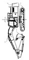
- FIG. 1 shows a hydraulic excavator according to this embodiment.
- the hydraulic excavator includes a traveling body 1, a swivel body 2 provided on the traveling body 1 so as to be swivel around a swivel shaft X, and a working device 3 mounted on the swivel body 2.
- a bucket 4 as a work tool is attached to the tip of the work device 3.
- the swivel body 2 is provided with a swivel motor 17 (shown in FIG. 2) and a speed reduction mechanism (not shown) thereof.
- the swivel motor 17 swivels and drives the swivel body 2 with respect to the traveling body 1.
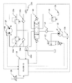
- FIG. 2 shows the hydraulic circuit of the hydraulic control device mounted on the hydraulic excavator (shown in FIG. 1).
- the parts related to the drive of the flood control actuator other than the swivel motor 17 are omitted.
- the hydraulic control device includes a variable displacement hydraulic pump 10, a pump regulator 10a capable of changing the discharge flow rate (pump flow rate) of the hydraulic pump 10, and a swivel motor 17.
- the pressure oil discharged from the hydraulic pump 10 is sent to the swivel motor 17 through the load check valve 13 and the directional control valve 14.
- the discharge pressure of the hydraulic pump 10 can be adjusted by controlling the opening of the oil passage with the hydraulic oil tank 21 by the bleed-off valve 12. Further, the discharge port of the hydraulic pump 10 is connected to the hydraulic oil tank 21 via the main relief valve 11.
- the main relief valve 11 defines the upper limit of the discharge pressure of the hydraulic pump 10.
- the two ports (A port and B port) of the swivel motor 17 are provided with swivel relief valves 15a and 15b and make-up check valves 16a and 16b, respectively.
- the swivel relief valves 15a and 15b have an overload prevention function of the swivel motor 17, and the make-up check valves 16a and 16b have an anti-void function of the swivel motor 17.
- the hydraulic control device in the present embodiment includes a rotation speed sensor 18 for detecting the rotation speed of the swivel motor 17, a controller 19, a joystick 20 as an operation device for inputting an operation signal, and A of the swivel motor 17. It is provided with pressure sensors 22a and 22b for detecting the pressure of the B port, respectively.
- the controller 19 acquires the actual rotation speed of the swivel motor 17 from the rotation speed sensor 18, acquires the swivel operation signal from the joystick 20, and acquires the A and B port pressures of the swivel motor 17 from the pressure sensors 22a and 22b.
- the controller 19 performs an operation based on these signals, and outputs a control signal to the pump regulator 10a, the bleed-off valve 12, and the directional control valve 14.
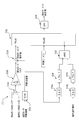
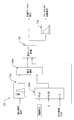
- FIG. 3 shows the control block of the controller 19.
- the control unit C1 inputs a turning operation signal and outputs a directional control valve control signal.
- the control unit C2 inputs a turning operation signal and outputs a target rotation speed.
- the control unit C3 inputs the actual rotation speed, the swivel motor A port pressure, and the swivel motor B port pressure, and outputs the swirl moment estimated value.
- the turning moment here represents the moment of inertia around the turning shaft X of the turning body 2 and the working device 3 as seen from the turning motor 17 side, and is assumed to include the influence of the speed reducer.
- the control unit C4 inputs the turning operation signal, the target rotation speed output by the control unit C2, and the actual rotation speed, and outputs the pressure control switching flag.
- the control unit C5 inputs the pressure control switching flag output by the control unit C4 and the turning operation signal, and outputs the target bleed-off opening.
- the control unit C6 inputs the turning equivalent moment, the turning operation signal, and the actual rotation speed output by the control unit C3, and outputs the turning target pressure.
- the control unit C7 is a target pump from the target rotation speed output by the control unit C2, the pressure control switching flag output by the control unit C4, the target bleed-off opening output by the control unit C5, and the turning target pressure output by the control unit C6. The flow rate is calculated, and the pump regulator control signal corresponding to this target pump flow rate is output.
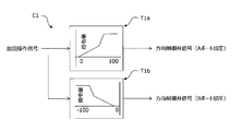
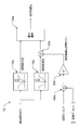
- FIG. 4 shows the details of the control unit C1.
- the control unit C1 inputs the turning operation signal to the control tables T1a and T1b, respectively.
- the control table T1a When the turning operation signal is positive, the control table T1a outputs a directional control valve control signal (A port pressurization) according to its magnitude.
- the control table T1b When the turning operation signal is negative, the control table T1b outputs a directional control valve control signal (B port pressurization) according to its magnitude.
- FIG. 5 shows the details of the control unit C2.
- the control unit C2 inputs a turning operation signal to the control table T2.
- the control table T2 outputs the target rotation speed of the turning motor according to the value of the turning operation signal.
- the target rotation speed is set to forward rotation, and it is associated with right turning.
- FIG. 6 shows the details of the control unit C3.
- the calculation units O3a and O3b calculate the swing motor torque by multiplying the differential pressure obtained by subtracting the B port pressure from the swing motor A port pressure by the swing motor volume q and dividing by 2 ⁇ .
- the calculation unit O3c differentiates the rotation speed of the swing motor and calculates the rotation acceleration.
- the calculation unit O3d calculates and outputs a turning moment estimated value by dividing the turning motor torque by the rotational acceleration.
- measures are taken to prevent zero division in the calculation unit O3d. Specific measures to prevent zero split include setting a minimum value for rotational acceleration.
- the calculation units O3e and O3f determine whether or not the absolute value of the turning motor rotational acceleration exceeds the threshold value Th1 preset in the controller 19.
- the calculation units O3g and O3h determine whether or not the turning operation signal exceeds the threshold value Th2 preset in the controller 19.
- the calculation unit O3i outputs TRUE when the outputs of the calculation units O3f and O3h are both TRUE.
- the calculation unit O3j outputs a value (estimated turning moment value) from the calculation unit O3d when the output of the calculation unit O3i is TRUE, and outputs a reference moment preset in the controller 19 in the case of FALSE.
- the calculation unit O3k performs a low-pass filter process on the output of the calculation unit O3j and outputs it as a turning moment estimated value.
- FIG. 7 shows the details of the control unit C4.
- the control unit O4a subtracts the actual rotation speed from the target rotation speed to calculate the rotation speed deviation.
- the control units O4b and O4c determine whether or not the turning operation signal exceeds 0, output 1 if it exceeds 0, and output -1 if it does not exceed 0.
- the control unit O4d multiplies the rotation speed deviation by the output (1 or -1) of the control unit O4c.
- the control unit O4e outputs the absolute value of the target rotation speed.
- the control unit O4f selects and outputs the maximum value of the absolute value of the target rotation speed and the minimum rotation speed W MIN (rotation speed at which the swing motor 17 can be regarded as almost stopped, for example, 10 rpm) set in advance in the controller. To do.
- the control unit O4g divides the rotation speed deviation by the output of the control unit O4f to calculate the rotation speed deviation ratio.
- Calculation unit O4h shall be such as speed deviation ratio threshold value R W (for example, 0.2 which is previously set rotational speed deviation ratio controller. In this case, the determination whether the speed deviation from the target value exceeds 20% things become to.) compared with the case above the speed deviation ratio threshold value R W outputs an oN as pressure control flag, if the following speed deviation ratio threshold value R W and outputs the OFF as a pressure control flag.
- speed deviation ratio threshold value R W for example, 0.2 which is previously set rotational speed deviation ratio controller.
- FIG. 8 shows the details of the control unit C5.
- the control table T5a converts the turning operation signal into a primary target bleed-off opening and outputs it.
- the control table T5a has a characteristic that the maximum opening is reached when the operation amount is minute (for example, ⁇ 10% of the maximum operation amount) or less, and the opening is zero when the operation amount exceeds this minute operation amount.
- the calculation unit O5a outputs a preset control opening (for example, a fixed value of 5 square mm) to the controller 19 when the pressure control flag is ON, and outputs 0 when the pressure control flag is OFF.
- the calculation unit O5b selects the maximum values of the output of the control table T5a and the output of the calculation unit O5a, and outputs them to the reduction rate limiting block C8.
- the reduction rate limiting block C8 calculates and outputs the target bleed-off opening based on the output of the calculation unit O5b and the pressure control flag.
- the control table T5b converts the target bleed-off opening into a bleed-off valve control signal and outputs it.
- FIG. 9 shows the details of the reduced rate limiting block C8.
- the calculation unit O8a outputs the value of the pressure control flag before the unit step time.
- the calculation unit O8b compares the values of the pressure control flag and the pressure control flag before the unit step time, outputs TRUE when the former becomes smaller than the latter (when the pressure control flag switches from ON to OFF), and calculates. Input to the SET terminal of unit O8c.
- the calculation unit O8c is a so-called flip-flop, and outputs TRUE when TRUE is input to the SET terminal, and continues to output TRUE until TRUE is input to the RESET terminal.
- the calculation unit O8d selects the rate r1 when the input from the calculation unit O8c is TRUE, selects the rate r2 when the input from the calculation unit O8c is TRUE, and outputs the rate r2 to the downward rate limiting calculation unit O8e.
- the rate r1 is set to a value limited so as to reduce the shock at the time of opening switching (for example, -10 square mm / sec), and the rate r2 is set to a value that can quickly switch the opening (for example, -1000 square mm / sec).
- the calculation unit O8e limits the falling rate of the input target opening based on the rate output from the calculation unit O8d, and outputs the input target opening to the calculation unit O8f.
- the calculation unit O8f determines whether or not the target opening after the downward rate limit is 0, and if it is 0, outputs TRUE and inputs it to the RESET terminal of the calculation unit O8c.
- FIG. 10 shows the details of the control unit C6.
- the control unit C6 inputs the turning operation signal to the control tables T6a and T6b.
- the control table T6a calculates the maximum turning pressure according to the turning operation signal.
- the control table T6b calculates the turning acceleration pressure according to the turning operation signal.
- the calculation units O6a and O6b divide the calculated value of the turning moment by the turning reference moment preset in the controller 19, and further multiply by the gain G1 preset in the controller 19 to obtain the turning acceleration pressure adjustment gain. Is calculated.
- the calculation unit O6c multiplies the turning acceleration pressure and the turning acceleration pressure adjustment gain, and outputs the result to the calculation unit O6d.
- the calculation unit O6d selects the output of the calculation unit O6c and the minimum value of the maximum turning pressure, and outputs the output as the turning target pressure.
- FIG. 11 shows the details of the control unit C7.
- the calculation unit O7a multiplies the actual rotation speed by the swirl motor volume q to calculate the actual swivel flow rate.
- the calculation unit O7b inputs the turning target pressure and the target bleed-off opening to the calculation unit O7b, sets c as a coefficient, A as the target opening, and p as the target pressure, and uses the relationship of cAp 1/2 to bleed-off flow rate target. Calculate the value.
- the calculation unit O7c adds the actual turning flow rate and the bleed-off flow rate target value, and inputs them to the calculation unit O7e.
- the calculation unit O7d calculates the turning target flow rate by multiplying the target rotation speed by the turning motor volume q.
- the calculation unit O7e selects and outputs the output of the calculation unit O7c, and when the pressure control flag is OFF, the calculation unit O7e selects and outputs the output of the calculation unit O7d.
- the output of the calculation unit O7e is output as the target pump flow rate through the low-pass filter O7f. Further, the control table T7 converts the target pump flow rate into a pump regulator command value and outputs it.
- FIG. 12 shows the time change of each signal and each control amount when the right turning full lever operation is performed in the state where the turning moment is small (the bucket 4 is empty).
- Graph (A) shows the time change of the turning operation signal.
- Graph (B) shows the time change of the target rotation speed and the actual rotation speed of the swing motor 17.
- the target rotation speed increases according to the turning operation signal, and the actual rotation speed increases as the turning motor pressure, which will be described later, rises.
- the graph (C) shows the ratio of the deviation between the target rotation speed and the actual rotation speed of the swing motor 17 to the target rotation speed (speed deviation ratio) and the time change of the rotation acceleration.
- the solid line speed deviation ratio in FIG, broken lines rotational acceleration, and a one-dot chain line shows a rotation acceleration thresholds Th1 and velocity deviation ratio threshold value R W.
- Graph (D) shows the time change of the port pressure of the swivel motor 17.
- the A port pressure on the drive side rises in relation to the bleed-off opening and the pump flow rate, which will be described later.
- Graph (E) shows the time change of the turning moment estimated value.
- the moment estimated value is used between the time t3 and the time t4, and the reference moment set in the controller 19 is used as the moment estimated value at other times.
- Graph (F) shows the time change of the pressure control flag.
- the pressure control flag is ON from time t1 to time t2.
- Graph (G) shows the time change of the bleed-off opening. From time t1 to time t2 when the pressure control flag is ON, the bleed-off opening maintains the control opening. Since the control flag changes from ON to OFF at time t2, the reduction rate limiting is activated and the opening is reduced at rate r1.
- the graph (H) shows the time change of the pump flow rate and the swirl motor flow rate.
- the pump flow rate is the minimum flow rate (standby flow rate).
- the pressure control flag is ON, the sum of the swivel motor flow rate and the bleed-off flow rate is discharged as the pump flow rate.
- the bleed-off flow rate is calculated as a flow rate at which the target pressure can be achieved while the bleed-off valve 12 maintains the control opening.
- the pressure control flag is turned off at time t2
- the pump target flow rate gradually approaches the swing motor flow rate due to the effect of the low-pass filter.
- FIG. 13 shows the time change of each signal and each control amount when the right turning full lever operation is performed in the state where the turning moment is large (the state where the bucket 4 contains the earth and sand).
- the rotational acceleration increasing rate of the actual rotational speed
- graph (B) the same turning pressure
- graph (E) the estimated moment value
- the rotation speed of the swivel motor 17 is detected in a hydraulic excavator provided with a swivel motor 17 for driving the swivel body 2 by supplying hydraulic oil from the hydraulic pump 10 and an operating device 20 for instructing the operation of the swivel body 2.
- a controller 19 is provided, and the controller 19 calculates the target rotation speed of the swivel motor 17 based on the input from the operating device 20, and calculates the degree of deviation of the rotation speed detected by the rotation speed sensor 18 from the target rotation speed.
- the pressure adjusting devices 10a and 12 are controlled so that the difference between the driving pressure detected by the pressure sensors 22a and 22b and the target driving pressure becomes small, and when the degree of deviation is equal to or less than a predetermined value, the rotation speed sensor 18 is used.
- the pressure adjusting devices 10a and 12 are controlled so that the difference between the detected rotation speed and the target rotation speed becomes small.
- the turning drive pressure of the motor 17 is controlled so as to coincide with set target drive pressure in accordance with the turning moment when the degree of deviation is equal to or less than the predetermined value R W (i.e., a swing motor)
- the driving pressure of the swivel motor 17 is controlled so that the rotation speed of the swivel motor 17 matches the target rotation speed.
- the rotation speed deviation ratio is used as the degree of deviation from the target rotation speed, but the rotation speed deviation may be used as the degree of deviation.
- the hydraulic excavator includes pressure sensors 22a and 22b for detecting the driving pressure of the swivel motor 17, and the controller 19 rotates the swivel motor 17 based on the rotation speed detected by the rotation speed sensor 18.
- the acceleration is calculated, and the turning moment is calculated based on the driving pressure detected by the pressure sensors 22a and 22b and the rotational acceleration. This makes it possible to accurately calculate the turning moment.
- the hydraulic pump 10 is a variable displacement type
- the pressure adjusting device capable of adjusting the driving pressure of the swirl motor 17 includes a pump regulator 10a capable of adjusting the discharge flow rate of the hydraulic pump 10 and a hydraulic pump. 10 and and a bleed-off valve 12 provided in a channel that connects the hydraulic oil tank 21, controller 19, the deviation degree in the case of less than the predetermined value R W, closed bleed-off valve 12
- the pump regulator 10a is controlled so that the difference between the rotation speed detected by the rotation speed sensor 18 and the target rotation speed becomes small.
- the discharge flow rate of the hydraulic pump 10 is controlled with the bleed-off valve 12 closed, so that the hydraulic loss can be reduced. ..
- the driving pressure of the swivel motor 17 is adjusted by controlling the discharge flow rate of the hydraulic pump 10 by changing the engine rotation speed, for example.
- the engine controller that controls the engine speed corresponds to the pressure regulator.
- the controller 19 if the degree of deviation is larger than a predetermined value R W is kept essentially stationary holding amount of opening of the bleed-off valve 12 to a predetermined opening amount (the control opening), the pressure sensor The pump regulator 10a is controlled so that the difference between the drive pressure detected by 22a and 22b and the target drive pressure becomes small. This makes it possible to accurately adjust the driving pressure of the swivel motor 17.
- the present invention is not limited to the above-mentioned examples, and includes various modifications.
- the above-described embodiment applies the present invention to a hydraulic excavator, the present invention is applicable to all construction machines provided with a swivel body.
- the above-described embodiment has been described in detail in order to explain the present invention in an easy-to-understand manner, and is not necessarily limited to the one including all the described configurations.
Landscapes
- Engineering & Computer Science (AREA)
- General Engineering & Computer Science (AREA)
- Mining & Mineral Resources (AREA)
- Civil Engineering (AREA)
- Structural Engineering (AREA)
- Physics & Mathematics (AREA)
- Fluid Mechanics (AREA)
- Mechanical Engineering (AREA)
- Operation Control Of Excavators (AREA)
- Fluid-Pressure Circuits (AREA)
Abstract
旋回モータの回転速度を速やかに目標回転速度に合わせることが可能な建設機械を提供する。 コントローラは、操作装置からの入力に基づいて旋回モータの目標回転速度を算出し、回転速度センサで検出した回転速度の前記目標回転速度からの乖離度合いを算出し、前記乖離度合いが所定の値より大きい場合は、旋回体および作業装置の旋回軸周りの慣性モーメントに応じて前記旋回モータの目標駆動圧力を設定すると共に、圧力センサで検出した駆動圧力と前記目標駆動圧力との差分が小さくなるように圧力調整装置を制御し、前記乖離度合いが前記所定の値以下の場合は、前記回転速度センサで検出した回転速度と前記目標回転速度との差分が小さくなるように前記圧力調整装置を制御する。
Description
本発明は、油圧ショベルなどの建設機械に関するものである。
旋回モータで旋回体を回転駆動する旋回式作業機械においては、油圧ポンプからの吐出油を旋回モータに取り付けられたリリーフ弁から排出することで、旋回モータ差圧をリリーフセット圧に保ち、旋回加速させる技術が公知である。
このような作業機械の旋回駆動装置においては、リリーフ弁から排出される高圧油は熱として捨てられるエネルギーとなるため、効率が悪い。これに対して、特許文献1では、操作量から求められる旋回モータの目標回転速度と、センサから検出する旋回モータの実回転速度の偏差から旋回モータ供給流量を決め、この旋回モータ供給流量が得られるようにポンプ流量を制御する。これにより、余剰流量を減らすことができ、エネルギー効率を改善するとしている。また、特許文献1では、目標回転速度と実回転速度の偏差にゲインを乗じたものを目標回転速度に加算して二次目標回転速度とし、これに基づきポンプ吐出流量を制御することで、速度追従性も調整できるとしている。
旋回モータの回転加速度は旋回モータトルク(旋回モータが固定容量式の場合は旋回モータの前後圧)で決まる。特許文献1では目標回転速度を補正することで速度追従性を調整するとしているが、旋回モータの前後圧はその時の旋回流量と旋回モータ回転速度から決まる出来なりの値か、あるいはリリーフ設定圧となる。したがって、旋回モータトルクを調整できず、オペレータが意図する所望の回転加速度を得られないおそれがある。
本発明は、上記課題に鑑みてなされたものであり、その目的は、旋回モータの回転速度を速やかに目標回転速度に合わせることが可能な建設機械を提供することにある。
上記目的を達成するために、本発明は、走行体と、前記走行体上に旋回可能に取り付けられた旋回体と、前記旋回体に取り付けられた作業装置と、作動油タンクと、前記作動油タンクから吸い込んだ作動油を吐出する油圧ポンプと、前記油圧ポンプから作動油が供給されて前記旋回体を駆動する旋回モータと、前記旋回体の動作を指示するための操作装置とを備えた建設機械において、前記旋回モータの回転速度を検出する回転速度センサと、前記旋回モータの駆動圧力を検出する圧力センサと、前記旋回モータの駆動圧力を調整可能な圧力調整装置と、前記圧力調整装置を制御するコントローラとを備え、前記コントローラは、前記操作装置からの入力に基づいて前記旋回モータの目標回転速度を算出し、前記回転速度センサで検出した回転速度の前記目標回転速度からの乖離度合いを算出し、前記乖離度合いが所定の値より大きい場合は、前記旋回体および前記作業装置の旋回軸周りの慣性モーメントに応じて前記旋回モータの目標駆動圧力を設定し、前記圧力センサで検出した駆動圧力と前記目標駆動圧力との差分が小さくなるように前記圧力調整装置を制御し、前記乖離度合いが前記所定の値以下の場合は、前記回転速度センサで検出した回転速度と前記目標回転速度との差分が小さくなるように前記圧力調整装置を制御するものとする。
以上のように構成した本発明によれば、旋回モータの回転速度の目標回転速度からの乖離度合いが所定の値より大きい場合(すなわち、旋回モータの回転速度が目標回転速度を大きく下回る場合)は、旋回モータの駆動圧力が旋回体および作業装置の旋回軸周りの慣性モーメントである旋回モーメントに応じて設定された目標駆動圧力と一致するように制御され、前記乖離度合いが前記所定の値以下の場合(すなわち、旋回モータの回転速度が目標回転速度に近づいた場合)は、旋回モータの回転速度が目標回転速度と一致するように旋回モータの駆動圧力が制御される。これにより、旋回モータの回転速度を速やかに目標回転速度に合わせることが可能となる。
本発明に係る建設機械によれば、旋回モータの回転速度を速やかに目標回転速度に合わせることが可能となる。
以下、建設機械として油圧ショベルを例にとって本発明の実施の形態を図面を用いて説明する。なお、各図中、同等の部材には同一の符号を付し、重複した説明は適宜省略する。
図1に本実施の形態に係る油圧ショベルを示す。図1において、油圧ショベルは、走行体1と、走行体1上に旋回軸Xを中心として旋回可能に設けた旋回体2と、旋回体2に装設した作業装置3とを備えている。作業装置3の先端には、作業具としてのバケット4が取り付けられている。旋回体2には、旋回モータ17(図2に示す)およびその減速機構(図示せず)が備えられている。旋回モータ17は、走行体1に対して旋回体2を旋回駆動させる。
図2に油圧ショベル(図1に示す)に搭載された油圧制御装置の油圧回路を示す。なお、図2では、旋回モータ17以外の油圧アクチュエータの駆動に関わる部分は省略している。
本実施の形態における油圧制御装置は、可変容量式の油圧ポンプ10と、油圧ポンプ10の吐出流量(ポンプ流量)を変更可能なポンプレギュレータ10aと、旋回モータ17とを備えている。油圧ポンプ10から吐出される圧油は、ロードチェック弁13と方向制御弁14とを通して旋回モータ17に送られる。油圧ポンプ10の吐出圧は、ブリードオフ弁12により作動油タンク21との油路開口を制御することで調整可能である。また、油圧ポンプ10の吐出ポートは、メインリリーフ弁11を介して作動油タンク21に接続されている。メインリリーフ弁11は、油圧ポンプ10の吐出圧の上限を規定する。
旋回モータ17の2つポート(AポートおよびBポート)には、それぞれ旋回リリーフ弁15a,15b、およびメイクアップ用チェック弁16a,16bが設けられている。旋回リリーフ弁15a,15bは旋回モータ17の過負荷防止機能を担っており、メイクアップ用チェック弁16a,16bは旋回モータ17のアンチボイド機能を担っている。
また、本実施の形態における油圧制御装置は、旋回モータ17の回転速度を検出する回転速度センサ18と、コントローラ19と、操作信号を入力する操作装置としてのジョイスティック20と、旋回モータ17のA,Bポートの圧力をそれぞれ検出する圧力センサ22a,22bとを備えている。コントローラ19は、回転速度センサ18から旋回モータ17の実回転速度を取得し、ジョイスティック20から旋回操作信号を取得し、圧力センサ22a,22bから旋回モータ17のA,Bポート圧を取得する。コントローラ19は、これらの信号を元に演算を行い、ポンプレギュレータ10a、ブリードオフ弁12、および方向制御弁14に制御信号を出力する。
図3にコントローラ19の制御ブロックを示す。制御部C1は、旋回操作信号を入力し、方向制御弁制御信号を出力する。制御部C2は、旋回操作信号を入力し、目標回転速度を出力する。制御部C3は、実回転速度と旋回モータAポート圧と旋回モータBポート圧とを入力し、旋回モーメント推定値を出力する。なお、ここでの旋回モーメントは、旋回モータ17側から見た旋回体2および作業装置3の旋回軸X周りの慣性モーメントを表し、減速機による影響も含んだものとする。
制御部C4は、旋回操作信号、制御部C2が出力した目標回転速度、および実回転速度を入力し、圧力制御切替フラグを出力する。制御部C5は、制御部C4が出力した圧力制御切替フラグ、および旋回操作信号を入力し、目標ブリードオフ開口を出力する。制御部C6は、制御部C3が出力した旋回等価モーメント、旋回操作信号、および実回転速度を入力し、旋回目標圧を出力する。制御部C7は、制御部C2が出力した目標回転速度、制御部C4が出力した圧力制御切替フラグ、制御部C5が出力した目標ブリードオフ開口、および制御部C6が出力した旋回目標圧から目標ポンプ流量を算出し、この目標ポンプ流量に対応したポンプレギュレータ制御信号を出力する。
図4に制御部C1の詳細を示す。制御部C1では、旋回操作信号を制御テーブルT1a,T1bにそれぞれ入力する。制御テーブルT1aは、旋回操作信号が正の時にその大きさに応じて方向制御弁制御信号(Aポート加圧)を出力する。制御テーブルT1bは、旋回操作信号が負の時にその大きさに応じて方向制御弁制御信号(Bポート加圧)を出力する。
図5に制御部C2の詳細を示す。制御部C2では、旋回操作信号を制御テーブルT2に入力する。制御テーブルT2は、旋回操作信号の値に応じて旋回モータの目標回転速度を出力する。ここで、旋回操作信号が正の時は目標回転速度は正回転とし、右旋回に対応付けるものとする。
図6に制御部C3の詳細を示す。演算部O3a,O3bは、旋回モータAポート圧からBポート圧を引いた差圧に旋回モータ容積qを乗算し、2πで除算することで旋回モータトルクを算出する。演算部O3cは、旋回モータ回転速度を微分し、回転加速度を算出する。演算部O3dは、旋回モータトルクを回転加速度で除算することで旋回モーメント推定値を算出し、出力する。なお、制御実装時には、演算部O3dにゼロ割防止の対策を行う。具体的なゼロ割防止対策としては、回転加速度の最小値を設ける、などがある。
演算部O3e,O3fは、旋回モータ回転加速度の絶対値がコントローラ19に予め設定された閾値Th1を超えるか否かを判定する。演算部O3g,O3hは、旋回操作信号がコントローラ19に予め設定された閾値Th2を超えるか否かを判定する。演算部O3iは、演算部O3f,O3hの出力が共にTRUEの場合にTRUEを出力する。演算部O3jは、演算部O3iの出力がTRUEの場合は演算部O3dからの値(旋回モーメント推定値)を出力し、FALSEの場合はコントローラ19に予め設定された基準モーメントを出力する。演算部O3kは、演算部O3jの出力にローパスフィルタ処理を行い、旋回モーメント推定値として出力する。
図7に制御部C4の詳細を示す。制御部O4aは、目標回転速度から実回転速度を減算し、回転速度偏差を算出する。制御部O4b,O4cは、旋回操作信号が0を上回るか否かを判定し、上回る場合は1を出力し、上回らない場合は-1を出力する。制御部O4dは、回転速度偏差に制御部O4cの出力(1または-1)を乗算する。制御部O4eは、目標回転速度の絶対値を出力する。制御部O4fは、目標回転速度の絶対値とコントローラに予め設定された最小回転速度WMIN(旋回モータ17がほぼ停止しているとみなせる回転速度。例えば10rpm)との最大値を選択して出力する。制御部O4gは、回転速度偏差を制御部O4fの出力で除算し、回転速度偏差比率を算出する。演算部O4hは、回転速度偏差比率をコントローラに予め設定されている速度偏差比率閾値RW(例えば0.2などとする。この場合は目標値に対する速度偏差が20%を超えるか否かを判定することになる。)と比較し、速度偏差比率閾値RWを上回る場合は圧力制御フラグとしてONを出力し、速度偏差比率閾値RW以下の場合は圧力制御フラグとしてOFFを出力する。
図8に制御部C5の詳細を示す。制御テーブルT5aは、旋回操作信号を一次目標ブリードオフ開口に変換し出力する。ここで制御テーブルT5aは、図8に示すように、微小な操作量(例えば最大操作量の±10%)以下で最大開口となり、この微小な操作量を超えたところでゼロとなる特性とする。演算部O5aは、圧力制御フラグがONの場合はコントローラ19に予め設定された制御開口(例えば5平方mm固定値)を出力し、圧力制御フラグがOFFの場合は0を出力する。演算部O5bは、制御テーブルT5aの出力と演算部O5aの出力の最大値を選択し、減少レート制限ブロックC8に出力する。減少レート制限ブロックC8は、演算部O5bの出力と圧力制御フラグとに基づいて目標ブリードオフ開口を算出し出力する。制御テーブルT5bは、目標ブリードオフ開口をブリードオフ弁制御信号に変換し出力する。
図9に減少レート制限ブロックC8の詳細を示す。演算部O8aは、圧力制御フラグの単位ステップ時間前の値を出力する。演算部O8bは、圧力制御フラグと圧力制御フラグの単位ステップ時間前の値を比較し、前者が後者よりも小さくなるとき(圧力制御フラグがONからOFFに切り替わるとき)にTRUEを出力し、演算部O8cのSET端子に入力する。演算部O8cはいわゆるフリップフロップであり、SET端子にTRUEが入力されるとTRUEを出力し、RESET端子にTRUEが入力されるまでTRUEを出力し続ける。演算部O8dは、演算部O8cからの入力がTRUEの時はレートr1を選択し、FALSEの時はレートr2を選択し、下降レート制限演算部O8eに出力する。ここで、レートr1は開口切替時のショックが少なくなるよう制限された値(例えば、-10平方mm毎秒)とし、レートr2は速やかに開口切替可能な値(例えば、-1000平方mm毎秒)とする。演算部O8eは、入力される目標開口を演算部O8dから出力されるレートに基づいて下降レート制限を行い、演算部O8fに出力する。演算部O8fは、下降レート制限後の目標開口が0か否かを判定し、0の場合はTRUEを出力し、演算部O8cのRESET端子に入力する。
図10に制御部C6の詳細を示す。制御部C6では、旋回操作信号を制御テーブルT6a,T6bに入力する。制御テーブルT6aは、旋回操作信号に応じた旋回最大圧を算出する。制御テーブルT6bは、旋回操作信号に応じた旋回加速圧を算出する。演算部O6a,O6bは、旋回モーメントの計算値を予めコントローラ19に設定されている旋回基準モーメントで除し、さらにコントローラ19に予め設定しているゲインG1を乗算することで、旋回加速圧調整ゲインを算出する。演算部O6cは、旋回加速圧と旋回加速圧調整ゲインを乗算し、演算部O6dに出力する。演算部O6dは、演算部O6cの出力と旋回最大圧の最小値を選択し、旋回目標圧として出力する。
図11に制御部C7の詳細を示す。演算部O7aは、実回転速度に旋回モータ容積qを乗算し、実旋回流量を算出する。演算部O7bは、旋回目標圧と目標ブリードオフ開口を演算部O7bを入力し、cを係数、Aを目標開口、pを目標圧として、cAp1/2の関係を利用してブリードオフ流量目標値を算出する。演算部O7cは、実旋回流量とブリードオフ流量目標値を加算し、演算部O7eに入力する。演算部O7dは、目標回転速度に旋回モータ容積qを乗算し、旋回目標流量を算出する。演算部O7eは、圧力制御フラグがONの場合は演算部O7cの出力を選択して出力し、圧力制御フラグがOFFの時は演算部O7dの出力を選択して出力する。演算部O7eの出力は、ローパスフィルタO7fを通して目標ポンプ流量として出力される。また、制御テーブルT7は、目標ポンプ流量をポンプレギュレータ指令値に変換し出力する。
図12に旋回モーメントが小さい状態(バケット4が空の状態)で右旋回フルレバー操作を行った場合の各信号および各制御量の時間変化を示す。
グラフ(A)は、旋回操作信号の時間変化を示す。
グラフ(B)は、旋回モータ17の目標回転速度および実回転速度の時間変化を示す。目標回転速度は旋回操作信号に従い上昇し、実回転速度は後述する旋回モータ圧力の上昇に伴って増加する。
グラフ(C)は、旋回モータ17の目標回転速度と実回転速度の偏差の目標回転速度に対する比率(速度偏差比率)と、回転加速度の時間変化を表す。図中の実線は速度偏差比率、破線は回転加速度、一点鎖線は回転加速度閾値Th1および速度偏差比率閾値RWを示す。旋回操作開始後、速度偏差比率が速度偏差比率閾値RWを上回る時刻をt1、速度偏差比率閾値RW以下となる時刻をt2とする。また、回転加速度が閾値Th1を上回る時刻をt3、閾値Th1以下となる時刻をt4とする。
グラフ(D)は、旋回モータ17のポート圧力の時間変化を示す。駆動側のAポート圧は、後述するブリードオフ開口とポンプ流量との関係で上昇する。
グラフ(E)は、旋回モーメント推定値の時間変化を示す。時刻t3から時刻t4の間はモーメント推定値を使用し、それ以外の時刻ではモーメント推定値としてコントローラ19に設定された基準モーメントを使用する。
グラフ(F)は、圧力制御フラグの時間変化を示す。圧力制御フラグは、時刻t1から時刻t2までONとなる。
グラフ(G)は、ブリードオフ開口の時間変化を示す。圧力制御フラグがONの時刻t1から時刻t2までは、ブリードオフ開口は制御開口を維持する。時刻t2では制御フラグがONからOFFに変化するため、減少レート制限が作動し、レートr1で開口が減少する。
グラフ(H)は、ポンプ流量と旋回モータ流量の時間変化を示す。非操作時はポンプ流量は最小流量(スタンバイ流量)となる。旋回操作が行われ、圧力制御フラグがONの時は旋回モータ流量にブリードオフ流量を足し合わせたものをポンプ流量として吐出する。ここで、ブリードオフ流量は、ブリードオフ弁12が制御開口を維持しているときに目標圧力を実現可能な流量として算出される。時刻t2で圧力制御フラグがOFFになると、ローパスフィルタの効果によりポンプ目標流量が徐々に旋回モータ流量に近づく。
図13に旋回モーメントが大きい状態(バケット4に土砂を収容した状態)で右旋回フルレバー操作を行った場合の各信号および各制御量の時間変化を示す。図12と異なり、旋回モーメントが大きくなるため、同じ旋回圧力に対して回転加速度(実回転速度の上昇率)が小さい(グラフ(B))。この時、モーメント推定値が大きく計算され(グラフ(E))、目標旋回圧が大きくなる。これにより、旋回モータ17の回転加速度を大きく低下させることなく旋回駆動を行うことが可能となる。
<効果>
本実施の形態では、走行体1と、走行体1上に旋回可能に取り付けられた旋回体2と、作動油タンク21と、作動油タンク21から吸い込んだ作動油を吐出する油圧ポンプ10と、油圧ポンプ10から作動油が供給されて旋回体2を駆動する旋回モータ17と、旋回体2の動作を指示するための操作装置20とを備えた油圧ショベルにおいて、旋回モータ17の回転速度を検出する回転速度センサ18と、旋回モータ17の駆動圧力を検出する圧力センサ22a,22bと、旋回モータ17の駆動圧力を調整可能な圧力調整装置10a,12と、圧力調整装置10a,12を制御するコントローラ19とを備え、コントローラ19は、操作装置20からの入力に基づいて旋回モータ17の目標回転速度を算出し、回転速度センサ18で検出した回転速度の前記目標回転速度からの乖離度合いを算出し、前記乖離度合いが所定の値RWより大きい場合は、旋回体2および作業装置3の旋回軸X周りの慣性モーメントである旋回モーメントに応じて旋回モータ17の目標駆動圧力を設定すると共に、圧力センサ22a,22bで検出した駆動圧力と前記目標駆動圧力との差分が小さくなるように圧力調整装置10a,12を制御し、前記乖離度合いが所定の値以下の場合は、回転速度センサ18で検出した回転速度と前記目標回転速度との差分が小さくなるように圧力調整装置10a,12を制御する。
本実施の形態では、走行体1と、走行体1上に旋回可能に取り付けられた旋回体2と、作動油タンク21と、作動油タンク21から吸い込んだ作動油を吐出する油圧ポンプ10と、油圧ポンプ10から作動油が供給されて旋回体2を駆動する旋回モータ17と、旋回体2の動作を指示するための操作装置20とを備えた油圧ショベルにおいて、旋回モータ17の回転速度を検出する回転速度センサ18と、旋回モータ17の駆動圧力を検出する圧力センサ22a,22bと、旋回モータ17の駆動圧力を調整可能な圧力調整装置10a,12と、圧力調整装置10a,12を制御するコントローラ19とを備え、コントローラ19は、操作装置20からの入力に基づいて旋回モータ17の目標回転速度を算出し、回転速度センサ18で検出した回転速度の前記目標回転速度からの乖離度合いを算出し、前記乖離度合いが所定の値RWより大きい場合は、旋回体2および作業装置3の旋回軸X周りの慣性モーメントである旋回モーメントに応じて旋回モータ17の目標駆動圧力を設定すると共に、圧力センサ22a,22bで検出した駆動圧力と前記目標駆動圧力との差分が小さくなるように圧力調整装置10a,12を制御し、前記乖離度合いが所定の値以下の場合は、回転速度センサ18で検出した回転速度と前記目標回転速度との差分が小さくなるように圧力調整装置10a,12を制御する。
以上のように構成した本実施の形態によれば、旋回モータ17の回転速度の目標回転速度からの乖離度合いが所定の値RWより大きい場合(すなわち、旋回モータ17の回転速度が目標回転速度を大きく下回る場合)は、旋回モータ17の駆動圧力が旋回モーメントに応じて設定された目標駆動圧力と一致するように制御され、前記乖離度合いが所定の値RW以下の場合(すなわち、旋回モータ17の回転速度が目標回転速度に近づいた場合)は、旋回モータ17の回転速度が目標回転速度と一致するように旋回モータ17の駆動圧力が制御される。これにより、旋回モータ17の回転速度を速やかに目標回転速度に合わせることが可能となる。なお、本実施の形態では、回転速度偏差比率を目標回転速度からの乖離度合いとして用いたが、回転速度偏差を乖離度合いとして用いてもよい。
また、本実施の形態に係る油圧ショベルは、旋回モータ17の駆動圧力を検出する圧力センサ22a,22bを備え、コントローラ19は、回転速度センサ18で検出した回転速度に基づいて旋回モータ17の回転加速度を算出し、圧力センサ22a,22bで検出した駆動圧力と前記回転加速度とに基づいて前記旋回モーメントを算出する。これにより、旋回モーメントを正確に算出することが可能となる。
また、本実施の形態では、油圧ポンプ10は可変容量式であり、旋回モータ17の駆動圧力を調整可能な圧力調整装置は、油圧ポンプ10の吐出流量を調整可能なポンプレギュレータ10aと、油圧ポンプ10と作動油タンク21とを接続する流路に設けられたブリードオフ弁12とを有し、コントローラ19は、前記乖離度合いが所定の値RW以下の場合は、ブリードオフ弁12を閉じた状態で、回転速度センサ18で検出した回転速度と前記目標回転速度との差分が小さくなるようにポンプレギュレータ10aを制御する。これにより、旋回モータ17の回転速度が目標回転速度に近づいたときは、ブリードオフ弁12を閉じた状態で油圧ポンプ10の吐出流量が制御されるため、油圧損失を低減することが可能となる。なお、油圧ポンプ10が固定容量式の場合は、例えばエンジン回転速度を変化させて油圧ポンプ10を吐出流量を制御することにより、旋回モータ17の駆動圧力を調整することになる。この場合、エンジン回転速度を制御するエンジンコントローラが圧力調整装置に相当する。
また、本実施の形態では、コントローラ19は、前記乖離度合いが所定の値RWより大きい場合は、ブリードオフ弁12の開口量を所定の開口量(制御開口)に保持した状態で、圧力センサ22a,22bで検出した駆動圧力と前記目標駆動圧力との差分が小さくなるようにポンプレギュレータ10aを制御する。これにより、旋回モータ17の駆動圧力を精度よく調整することが可能となる。
以上、本発明の実施例について詳述したが、本発明は、上記した実施例に限定されるものではなく、様々な変形例が含まれる。例えば、上記した実施例は、油圧ショベルに本発明を適用したものであるが、本発明は旋回体を備えた建設機械全般に適用可能である。また、上記した実施例は、本発明を分かり易く説明するために詳細に説明したものであり、必ずしも説明した全ての構成を備えるものに限定されるものではない。
1…走行体、2…旋回体、3…作業装置、4…バケット、10…油圧ポンプ、10a…ポンプレギュレータ(圧力調整装置)、11…メインリリーフ弁、12…ブリードオフ弁(圧力調整装置)、13…ロードチェック弁、14…方向制御弁、15a,15b…旋回リリーフ弁、16a,16b…メイクアップ用チェック弁、17…旋回モータ、18…回転速度センサ、19…コントローラ、20…ジョイスティック(操作装置)、21…作動油タンク、22a,22b…圧力センサ。
Claims (4)
- 走行体と、
前記走行体上に旋回可能に取り付けられた旋回体と、
前記旋回体に取り付けられた作業装置と、
作動油タンクと、
前記作動油タンクから吸い込んだ作動油を吐出する油圧ポンプと、
前記油圧ポンプから作動油が供給されて前記旋回体を駆動する旋回モータと、
前記旋回体の動作を指示するための操作装置とを備えた建設機械において、
前記旋回モータの回転速度を検出する回転速度センサと、
前記旋回モータの駆動圧力を検出する圧力センサと、
前記旋回モータの駆動圧力を調整可能な圧力調整装置と、
前記圧力調整装置を制御するコントローラとを備え、
前記コントローラは、
前記操作装置からの入力に基づいて前記旋回モータの目標回転速度を算出し、
前記回転速度センサで検出した回転速度の前記目標回転速度からの乖離度合いを算出し、
前記乖離度合いが所定の値より大きい場合は、前記旋回体および前記作業装置の旋回軸周りの慣性モーメントである旋回モーメントに応じて前記旋回モータの目標駆動圧力を設定すると共に、前記圧力センサで検出した駆動圧力と前記目標駆動圧力との差分が小さくなるように前記圧力調整装置を制御し、
前記乖離度合いが前記所定の値以下の場合は、前記回転速度センサで検出した回転速度と前記目標回転速度との差分が小さくなるように前記圧力調整装置を制御する
ことを特徴とする建設機械。 - 請求項1に記載の建設機械において、
前記コントローラは、
前記回転速度センサで検出した回転速度に基づいて前記旋回モータの回転加速度を算出し、
前記圧力センサで検出した駆動圧力と前記回転加速度とに基づいて前記旋回モーメントを算出する
ことを特徴とする建設機械。 - 請求項1に記載の建設機械において、
前記油圧ポンプは可変容量式であり、
前記圧力調整装置は、前記油圧ポンプの吐出流量を調整可能なポンプレギュレータと、前記油圧ポンプと前記作動油タンクとを接続する流路に設けられたブリードオフ弁とを有し、
前記コントローラは、前記乖離度合いが前記所定の値以下の場合は、前記ブリードオフ弁を閉じた状態で、前記回転速度センサで検出した回転速度と前記目標回転速度との差分が小さくなるように前記ポンプレギュレータを制御する
ことを特徴とする建設機械。 - 請求項1に記載の建設機械において、
前記油圧ポンプは可変容量式であり、
前記圧力調整装置は、前記油圧ポンプの吐出流量を調整可能なポンプレギュレータと、前記油圧ポンプと前記作動油タンクとを接続する流路に設けられたブリードオフ弁とを有し、
前記コントローラは、前記乖離度合いが前記所定の値より大きい場合は、前記ブリードオフ弁の開口量を所定の開口量に保持した状態で、前記圧力センサで検出した駆動圧力と前記目標駆動圧力との差分が小さくなるように前記ポンプレギュレータを制御する
ことを特徴とする建設機械。
Priority Applications (4)
| Application Number | Priority Date | Filing Date | Title |
|---|---|---|---|
| EP20865650.4A EP3995700B1 (en) | 2019-09-20 | 2020-08-28 | Construction machine |
| CN202080058102.2A CN114270052B (zh) | 2019-09-20 | 2020-08-28 | 工程机械 |
| KR1020227004940A KR102571723B1 (ko) | 2019-09-20 | 2020-08-28 | 건설기계 |
| US17/632,668 US11781285B2 (en) | 2019-09-20 | 2020-08-28 | Construction machine |
Applications Claiming Priority (2)
| Application Number | Priority Date | Filing Date | Title |
|---|---|---|---|
| JP2019-172094 | 2019-09-20 | ||
| JP2019172094A JP7236365B2 (ja) | 2019-09-20 | 2019-09-20 | 建設機械 |
Publications (1)
| Publication Number | Publication Date |
|---|---|
| WO2021054088A1 true WO2021054088A1 (ja) | 2021-03-25 |
Family
ID=74883516
Family Applications (1)
| Application Number | Title | Priority Date | Filing Date |
|---|---|---|---|
| PCT/JP2020/032712 Ceased WO2021054088A1 (ja) | 2019-09-20 | 2020-08-28 | 建設機械 |
Country Status (6)
| Country | Link |
|---|---|
| US (1) | US11781285B2 (ja) |
| EP (1) | EP3995700B1 (ja) |
| JP (1) | JP7236365B2 (ja) |
| KR (1) | KR102571723B1 (ja) |
| CN (1) | CN114270052B (ja) |
| WO (1) | WO2021054088A1 (ja) |
Families Citing this family (5)
| Publication number | Priority date | Publication date | Assignee | Title |
|---|---|---|---|---|
| EP4585808A1 (en) * | 2022-09-29 | 2025-07-16 | Hitachi Construction Machinery Co., Ltd. | Work machine |
| CN116576168B (zh) * | 2023-04-04 | 2026-02-06 | 中联重科股份有限公司 | 工程机械回转驱动控制方法、装置、处理器及存储介质 |
| JP7783848B2 (ja) * | 2023-04-07 | 2025-12-10 | 株式会社竹内製作所 | 作業用車両 |
| CN117803037B (zh) * | 2023-12-28 | 2025-10-24 | 潍柴动力股份有限公司 | 一种挖掘机回转平台的控制方法及挖掘机 |
| CN119641732B (zh) * | 2024-12-13 | 2026-04-21 | 江苏汇智高端工程机械创新中心有限公司 | 一种回转马达起动控制系统及方法 |
Citations (3)
| Publication number | Priority date | Publication date | Assignee | Title |
|---|---|---|---|---|
| JPH0276906A (ja) * | 1988-09-09 | 1990-03-16 | Kayaba Ind Co Ltd | 液圧アクチュエータの制御回路 |
| JPH1181389A (ja) * | 1997-09-03 | 1999-03-26 | Hitachi Constr Mach Co Ltd | 油圧制御装置 |
| JP2012246944A (ja) | 2011-05-25 | 2012-12-13 | Kobelco Contstruction Machinery Ltd | 旋回式作業機械 |
Family Cites Families (15)
| Publication number | Priority date | Publication date | Assignee | Title |
|---|---|---|---|---|
| JP2744117B2 (ja) * | 1990-06-05 | 1998-04-28 | 株式会社神戸製鋼所 | クレーン等の旋回制御装置 |
| JP3730336B2 (ja) * | 1995-11-06 | 2006-01-05 | 株式会社神戸製鋼所 | 油圧アクチュエータの速度制御装置 |
| JP5084295B2 (ja) * | 2007-02-09 | 2012-11-28 | 日立建機株式会社 | 油圧建設機械のポンプトルク制御装置 |
| JP2013234683A (ja) * | 2012-05-02 | 2013-11-21 | Toshiba Mach Co Ltd | 作業機械の旋回装置並びにその作業機械 |
| JP5873456B2 (ja) * | 2013-04-05 | 2016-03-01 | 川崎重工業株式会社 | 作業機械の駆動制御システム、それを備える作業機械、及びその駆動制御方法 |
| FR3005703B1 (fr) * | 2013-05-14 | 2016-08-19 | Machine Smart | Systeme hydraulique a controle electronique de pression et de debit |
| JP5969437B2 (ja) * | 2013-08-22 | 2016-08-17 | 日立建機株式会社 | 建設機械 |
| JP6149819B2 (ja) * | 2014-07-30 | 2017-06-21 | コベルコ建機株式会社 | 建設機械の旋回制御装置 |
| EP3249111B1 (en) * | 2015-01-08 | 2019-08-14 | Volvo Construction Equipment AB | Method for controlling flow rate of hydraulic pump of construction machine |
| KR101840247B1 (ko) * | 2016-01-20 | 2018-03-20 | 가부시키가이샤 고마쓰 세이사쿠쇼 | 작업 기계의 기관 제어 장치, 작업 기계 및 작업 기계의 기관 제어 방법 |
| JP6842856B2 (ja) * | 2016-07-26 | 2021-03-17 | 川崎重工業株式会社 | 液圧駆動システム |
| US10100494B2 (en) * | 2016-08-12 | 2018-10-16 | Caterpillar Inc. | Closed-loop control of swing |
| JP7006346B2 (ja) * | 2018-02-13 | 2022-01-24 | コベルコ建機株式会社 | 旋回式作業機械 |
| JP7006350B2 (ja) * | 2018-02-15 | 2022-01-24 | コベルコ建機株式会社 | 旋回式油圧作業機械 |
| JP7400552B2 (ja) * | 2020-03-06 | 2023-12-19 | コベルコ建機株式会社 | 作業機械の油圧駆動装置 |
-
2019
- 2019-09-20 JP JP2019172094A patent/JP7236365B2/ja active Active
-
2020
- 2020-08-28 KR KR1020227004940A patent/KR102571723B1/ko active Active
- 2020-08-28 US US17/632,668 patent/US11781285B2/en active Active
- 2020-08-28 CN CN202080058102.2A patent/CN114270052B/zh active Active
- 2020-08-28 WO PCT/JP2020/032712 patent/WO2021054088A1/ja not_active Ceased
- 2020-08-28 EP EP20865650.4A patent/EP3995700B1/en active Active
Patent Citations (3)
| Publication number | Priority date | Publication date | Assignee | Title |
|---|---|---|---|---|
| JPH0276906A (ja) * | 1988-09-09 | 1990-03-16 | Kayaba Ind Co Ltd | 液圧アクチュエータの制御回路 |
| JPH1181389A (ja) * | 1997-09-03 | 1999-03-26 | Hitachi Constr Mach Co Ltd | 油圧制御装置 |
| JP2012246944A (ja) | 2011-05-25 | 2012-12-13 | Kobelco Contstruction Machinery Ltd | 旋回式作業機械 |
Also Published As
| Publication number | Publication date |
|---|---|
| JP7236365B2 (ja) | 2023-03-09 |
| US20220282450A1 (en) | 2022-09-08 |
| KR20220033514A (ko) | 2022-03-16 |
| CN114270052A (zh) | 2022-04-01 |
| US11781285B2 (en) | 2023-10-10 |
| CN114270052B (zh) | 2024-04-09 |
| EP3995700A4 (en) | 2023-07-19 |
| EP3995700B1 (en) | 2024-05-15 |
| KR102571723B1 (ko) | 2023-08-28 |
| EP3995700A1 (en) | 2022-05-11 |
| JP2021050744A (ja) | 2021-04-01 |
Similar Documents
| Publication | Publication Date | Title |
|---|---|---|
| WO2021054088A1 (ja) | 建設機械 | |
| JP5738674B2 (ja) | 旋回式作業機械 | |
| JP6317656B2 (ja) | 作業機械の油圧駆動システム | |
| JP5886976B2 (ja) | 作業機械 | |
| JP6072310B2 (ja) | 作業機械の圧油エネルギ回収装置 | |
| CN110325747B (zh) | 作业机械 | |
| JP2016080009A (ja) | 建設機械の油圧駆動システム | |
| JP6190944B2 (ja) | 建設機械 | |
| JPWO2018164263A1 (ja) | ショベル | |
| WO2019224879A1 (ja) | 建設機械の油圧駆動システム | |
| JP2017115942A (ja) | 作業機械 | |
| JP2015197185A (ja) | 作業機械の油圧制御装置 | |
| JP2013545948A (ja) | 建設機械の油圧ポンプ制御システム | |
| JP4979014B2 (ja) | 油圧ショベルにおける旋回ポンプの制御システム | |
| JP2002120990A (ja) | 建設機械の旋回制御装置 | |
| JP6955349B2 (ja) | 建設機械の油圧駆動システム | |
| JP7223264B2 (ja) | 建設機械 | |
| JP2012002261A (ja) | 旋回体駆動用の液圧装置 | |
| WO2019224877A1 (ja) | 建設機械の油圧駆動システム | |
| WO2024071389A1 (ja) | 作業機械 | |
| JP2022132776A (ja) | 油圧システム | |
| JPH11181839A (ja) | 旋回作業機の旋回制御装置 | |
| JP2020200882A (ja) | 作業機械 | |
| KR20150081615A (ko) | 건설기계의 유압시스템 |
Legal Events
| Date | Code | Title | Description |
|---|---|---|---|
| 121 | Ep: the epo has been informed by wipo that ep was designated in this application |
Ref document number: 20865650 Country of ref document: EP Kind code of ref document: A1 |
|
| ENP | Entry into the national phase |
Ref document number: 2020865650 Country of ref document: EP Effective date: 20220203 |
|
| ENP | Entry into the national phase |
Ref document number: 20227004940 Country of ref document: KR Kind code of ref document: A |
|
| NENP | Non-entry into the national phase |
Ref country code: DE |