WO2021054132A1 - 車両給電システム - Google Patents
車両給電システム Download PDFInfo
- Publication number
- WO2021054132A1 WO2021054132A1 PCT/JP2020/033375 JP2020033375W WO2021054132A1 WO 2021054132 A1 WO2021054132 A1 WO 2021054132A1 JP 2020033375 W JP2020033375 W JP 2020033375W WO 2021054132 A1 WO2021054132 A1 WO 2021054132A1
- Authority
- WO
- WIPO (PCT)
- Prior art keywords
- power supply
- vehicle
- segment
- power
- control device
- Prior art date
- Legal status (The legal status is an assumption and is not a legal conclusion. Google has not performed a legal analysis and makes no representation as to the accuracy of the status listed.)
- Ceased
Links
Images



Classifications
-
- B—PERFORMING OPERATIONS; TRANSPORTING
- B60—VEHICLES IN GENERAL
- B60L—PROPULSION OF ELECTRICALLY-PROPELLED VEHICLES; SUPPLYING ELECTRIC POWER FOR AUXILIARY EQUIPMENT OF ELECTRICALLY-PROPELLED VEHICLES; ELECTRODYNAMIC BRAKE SYSTEMS FOR VEHICLES IN GENERAL; MAGNETIC SUSPENSION OR LEVITATION FOR VEHICLES; MONITORING OPERATING VARIABLES OF ELECTRICALLY-PROPELLED VEHICLES; ELECTRIC SAFETY DEVICES FOR ELECTRICALLY-PROPELLED VEHICLES
- B60L53/00—Methods of charging batteries, specially adapted for electric vehicles; Charging stations or on-board charging equipment therefor; Exchange of energy storage elements in electric vehicles
- B60L53/10—Methods of charging batteries, specially adapted for electric vehicles; Charging stations or on-board charging equipment therefor; Exchange of energy storage elements in electric vehicles characterised by the energy transfer between the charging station and the vehicle
- B60L53/12—Inductive energy transfer
- B60L53/122—Circuits or methods for driving the primary coil, e.g. supplying electric power to the coil
-
- B—PERFORMING OPERATIONS; TRANSPORTING
- B60—VEHICLES IN GENERAL
- B60L—PROPULSION OF ELECTRICALLY-PROPELLED VEHICLES; SUPPLYING ELECTRIC POWER FOR AUXILIARY EQUIPMENT OF ELECTRICALLY-PROPELLED VEHICLES; ELECTRODYNAMIC BRAKE SYSTEMS FOR VEHICLES IN GENERAL; MAGNETIC SUSPENSION OR LEVITATION FOR VEHICLES; MONITORING OPERATING VARIABLES OF ELECTRICALLY-PROPELLED VEHICLES; ELECTRIC SAFETY DEVICES FOR ELECTRICALLY-PROPELLED VEHICLES
- B60L5/00—Current collectors for power supply lines of electrically-propelled vehicles
-
- B—PERFORMING OPERATIONS; TRANSPORTING
- B60—VEHICLES IN GENERAL
- B60L—PROPULSION OF ELECTRICALLY-PROPELLED VEHICLES; SUPPLYING ELECTRIC POWER FOR AUXILIARY EQUIPMENT OF ELECTRICALLY-PROPELLED VEHICLES; ELECTRODYNAMIC BRAKE SYSTEMS FOR VEHICLES IN GENERAL; MAGNETIC SUSPENSION OR LEVITATION FOR VEHICLES; MONITORING OPERATING VARIABLES OF ELECTRICALLY-PROPELLED VEHICLES; ELECTRIC SAFETY DEVICES FOR ELECTRICALLY-PROPELLED VEHICLES
- B60L5/00—Current collectors for power supply lines of electrically-propelled vehicles
- B60L5/005—Current collectors for power supply lines of electrically-propelled vehicles without mechanical contact between the collector and the power supply line
-
- B—PERFORMING OPERATIONS; TRANSPORTING
- B60—VEHICLES IN GENERAL
- B60L—PROPULSION OF ELECTRICALLY-PROPELLED VEHICLES; SUPPLYING ELECTRIC POWER FOR AUXILIARY EQUIPMENT OF ELECTRICALLY-PROPELLED VEHICLES; ELECTRODYNAMIC BRAKE SYSTEMS FOR VEHICLES IN GENERAL; MAGNETIC SUSPENSION OR LEVITATION FOR VEHICLES; MONITORING OPERATING VARIABLES OF ELECTRICALLY-PROPELLED VEHICLES; ELECTRIC SAFETY DEVICES FOR ELECTRICALLY-PROPELLED VEHICLES
- B60L53/00—Methods of charging batteries, specially adapted for electric vehicles; Charging stations or on-board charging equipment therefor; Exchange of energy storage elements in electric vehicles
- B60L53/30—Constructional details of charging stations
- B60L53/35—Means for automatic or assisted adjustment of the relative position of charging devices and vehicles
- B60L53/38—Means for automatic or assisted adjustment of the relative position of charging devices and vehicles specially adapted for charging by inductive energy transfer
- B60L53/39—Means for automatic or assisted adjustment of the relative position of charging devices and vehicles specially adapted for charging by inductive energy transfer with position-responsive activation of primary coils
-
- B—PERFORMING OPERATIONS; TRANSPORTING
- B60—VEHICLES IN GENERAL
- B60L—PROPULSION OF ELECTRICALLY-PROPELLED VEHICLES; SUPPLYING ELECTRIC POWER FOR AUXILIARY EQUIPMENT OF ELECTRICALLY-PROPELLED VEHICLES; ELECTRODYNAMIC BRAKE SYSTEMS FOR VEHICLES IN GENERAL; MAGNETIC SUSPENSION OR LEVITATION FOR VEHICLES; MONITORING OPERATING VARIABLES OF ELECTRICALLY-PROPELLED VEHICLES; ELECTRIC SAFETY DEVICES FOR ELECTRICALLY-PROPELLED VEHICLES
- B60L53/00—Methods of charging batteries, specially adapted for electric vehicles; Charging stations or on-board charging equipment therefor; Exchange of energy storage elements in electric vehicles
- B60L53/60—Monitoring or controlling charging stations
- B60L53/66—Data transfer between charging stations and vehicles
-
- B—PERFORMING OPERATIONS; TRANSPORTING
- B60—VEHICLES IN GENERAL
- B60L—PROPULSION OF ELECTRICALLY-PROPELLED VEHICLES; SUPPLYING ELECTRIC POWER FOR AUXILIARY EQUIPMENT OF ELECTRICALLY-PROPELLED VEHICLES; ELECTRODYNAMIC BRAKE SYSTEMS FOR VEHICLES IN GENERAL; MAGNETIC SUSPENSION OR LEVITATION FOR VEHICLES; MONITORING OPERATING VARIABLES OF ELECTRICALLY-PROPELLED VEHICLES; ELECTRIC SAFETY DEVICES FOR ELECTRICALLY-PROPELLED VEHICLES
- B60L9/00—Electric propulsion with power supply external to the vehicle
-
- B—PERFORMING OPERATIONS; TRANSPORTING
- B60—VEHICLES IN GENERAL
- B60M—POWER SUPPLY LINES, AND DEVICES ALONG RAILS, FOR ELECTRICALLY- PROPELLED VEHICLES
- B60M1/00—Power supply lines for contact with collector on vehicle
- B60M1/36—Single contact pieces along the line for power supply
-
- B—PERFORMING OPERATIONS; TRANSPORTING
- B60—VEHICLES IN GENERAL
- B60M—POWER SUPPLY LINES, AND DEVICES ALONG RAILS, FOR ELECTRICALLY- PROPELLED VEHICLES
- B60M3/00—Feeding power to supply lines in contact with collector on vehicles; Arrangements for consuming regenerative power
- B60M3/04—Arrangements for cutting in and out of individual track sections
-
- B—PERFORMING OPERATIONS; TRANSPORTING
- B60—VEHICLES IN GENERAL
- B60M—POWER SUPPLY LINES, AND DEVICES ALONG RAILS, FOR ELECTRICALLY- PROPELLED VEHICLES
- B60M7/00—Power lines or rails specially adapted for electrically-propelled vehicles of special types, e.g. suspension tramway, ropeway, underground railway
-
- H—ELECTRICITY
- H02—GENERATION; CONVERSION OR DISTRIBUTION OF ELECTRIC POWER
- H02J—ELECTRIC POWER NETWORKS; CIRCUIT ARRANGEMENTS OR SYSTEMS FOR SUPPLYING OR DISTRIBUTING ELECTRIC POWER; SYSTEMS FOR STORING ELECTRIC ENERGY
- H02J50/00—Circuit arrangements or systems for wireless supply or distribution of electric power
- H02J50/005—Mechanical details of housing or structure aiming to accommodate the power transfer means, e.g. mechanical integration of coils, antennas or transducers into emitting or receiving devices
-
- H—ELECTRICITY
- H02—GENERATION; CONVERSION OR DISTRIBUTION OF ELECTRIC POWER
- H02J—ELECTRIC POWER NETWORKS; CIRCUIT ARRANGEMENTS OR SYSTEMS FOR SUPPLYING OR DISTRIBUTING ELECTRIC POWER; SYSTEMS FOR STORING ELECTRIC ENERGY
- H02J50/00—Circuit arrangements or systems for wireless supply or distribution of electric power
- H02J50/10—Circuit arrangements or systems for wireless supply or distribution of electric power using inductive coupling
-
- H—ELECTRICITY
- H02—GENERATION; CONVERSION OR DISTRIBUTION OF ELECTRIC POWER
- H02J—ELECTRIC POWER NETWORKS; CIRCUIT ARRANGEMENTS OR SYSTEMS FOR SUPPLYING OR DISTRIBUTING ELECTRIC POWER; SYSTEMS FOR STORING ELECTRIC ENERGY
- H02J50/00—Circuit arrangements or systems for wireless supply or distribution of electric power
- H02J50/10—Circuit arrangements or systems for wireless supply or distribution of electric power using inductive coupling
- H02J50/12—Circuit arrangements or systems for wireless supply or distribution of electric power using inductive coupling of the resonant type
-
- H—ELECTRICITY
- H02—GENERATION; CONVERSION OR DISTRIBUTION OF ELECTRIC POWER
- H02J—ELECTRIC POWER NETWORKS; CIRCUIT ARRANGEMENTS OR SYSTEMS FOR SUPPLYING OR DISTRIBUTING ELECTRIC POWER; SYSTEMS FOR STORING ELECTRIC ENERGY
- H02J50/00—Circuit arrangements or systems for wireless supply or distribution of electric power
- H02J50/40—Circuit arrangements or systems for wireless supply or distribution of electric power using two or more transmitting or receiving devices
-
- H—ELECTRICITY
- H02—GENERATION; CONVERSION OR DISTRIBUTION OF ELECTRIC POWER
- H02J—ELECTRIC POWER NETWORKS; CIRCUIT ARRANGEMENTS OR SYSTEMS FOR SUPPLYING OR DISTRIBUTING ELECTRIC POWER; SYSTEMS FOR STORING ELECTRIC ENERGY
- H02J50/00—Circuit arrangements or systems for wireless supply or distribution of electric power
- H02J50/80—Circuit arrangements or systems for wireless supply or distribution of electric power involving the exchange of data, concerning supply or distribution of electric power, between transmitting devices and receiving devices
-
- H—ELECTRICITY
- H02—GENERATION; CONVERSION OR DISTRIBUTION OF ELECTRIC POWER
- H02J—ELECTRIC POWER NETWORKS; CIRCUIT ARRANGEMENTS OR SYSTEMS FOR SUPPLYING OR DISTRIBUTING ELECTRIC POWER; SYSTEMS FOR STORING ELECTRIC ENERGY
- H02J50/00—Circuit arrangements or systems for wireless supply or distribution of electric power
- H02J50/90—Circuit arrangements or systems for wireless supply or distribution of electric power involving detection or optimisation of position, e.g. alignment
-
- H—ELECTRICITY
- H02—GENERATION; CONVERSION OR DISTRIBUTION OF ELECTRIC POWER
- H02J—ELECTRIC POWER NETWORKS; CIRCUIT ARRANGEMENTS OR SYSTEMS FOR SUPPLYING OR DISTRIBUTING ELECTRIC POWER; SYSTEMS FOR STORING ELECTRIC ENERGY
- H02J7/00—Circuit arrangements for charging or discharging batteries or for supplying loads from batteries
- H02J7/90—Regulation of charging or discharging current or voltage
-
- B—PERFORMING OPERATIONS; TRANSPORTING
- B60—VEHICLES IN GENERAL
- B60L—PROPULSION OF ELECTRICALLY-PROPELLED VEHICLES; SUPPLYING ELECTRIC POWER FOR AUXILIARY EQUIPMENT OF ELECTRICALLY-PROPELLED VEHICLES; ELECTRODYNAMIC BRAKE SYSTEMS FOR VEHICLES IN GENERAL; MAGNETIC SUSPENSION OR LEVITATION FOR VEHICLES; MONITORING OPERATING VARIABLES OF ELECTRICALLY-PROPELLED VEHICLES; ELECTRIC SAFETY DEVICES FOR ELECTRICALLY-PROPELLED VEHICLES
- B60L2240/00—Control parameters of input or output; Target parameters
- B60L2240/10—Vehicle control parameters
- B60L2240/12—Speed
-
- B—PERFORMING OPERATIONS; TRANSPORTING
- B60—VEHICLES IN GENERAL
- B60L—PROPULSION OF ELECTRICALLY-PROPELLED VEHICLES; SUPPLYING ELECTRIC POWER FOR AUXILIARY EQUIPMENT OF ELECTRICALLY-PROPELLED VEHICLES; ELECTRODYNAMIC BRAKE SYSTEMS FOR VEHICLES IN GENERAL; MAGNETIC SUSPENSION OR LEVITATION FOR VEHICLES; MONITORING OPERATING VARIABLES OF ELECTRICALLY-PROPELLED VEHICLES; ELECTRIC SAFETY DEVICES FOR ELECTRICALLY-PROPELLED VEHICLES
- B60L2240/00—Control parameters of input or output; Target parameters
- B60L2240/10—Vehicle control parameters
- B60L2240/14—Acceleration
- B60L2240/16—Acceleration longitudinal
-
- Y—GENERAL TAGGING OF NEW TECHNOLOGICAL DEVELOPMENTS; GENERAL TAGGING OF CROSS-SECTIONAL TECHNOLOGIES SPANNING OVER SEVERAL SECTIONS OF THE IPC; TECHNICAL SUBJECTS COVERED BY FORMER USPC CROSS-REFERENCE ART COLLECTIONS [XRACs] AND DIGESTS
- Y02—TECHNOLOGIES OR APPLICATIONS FOR MITIGATION OR ADAPTATION AGAINST CLIMATE CHANGE
- Y02T—CLIMATE CHANGE MITIGATION TECHNOLOGIES RELATED TO TRANSPORTATION
- Y02T10/00—Road transport of goods or passengers
- Y02T10/60—Other road transportation technologies with climate change mitigation effect
- Y02T10/70—Energy storage systems for electromobility, e.g. batteries
-
- Y—GENERAL TAGGING OF NEW TECHNOLOGICAL DEVELOPMENTS; GENERAL TAGGING OF CROSS-SECTIONAL TECHNOLOGIES SPANNING OVER SEVERAL SECTIONS OF THE IPC; TECHNICAL SUBJECTS COVERED BY FORMER USPC CROSS-REFERENCE ART COLLECTIONS [XRACs] AND DIGESTS
- Y02—TECHNOLOGIES OR APPLICATIONS FOR MITIGATION OR ADAPTATION AGAINST CLIMATE CHANGE
- Y02T—CLIMATE CHANGE MITIGATION TECHNOLOGIES RELATED TO TRANSPORTATION
- Y02T10/00—Road transport of goods or passengers
- Y02T10/60—Other road transportation technologies with climate change mitigation effect
- Y02T10/7072—Electromobility specific charging systems or methods for batteries, ultracapacitors, supercapacitors or double-layer capacitors
Definitions
- the present disclosure relates to a technology for supplying power to a vehicle that can travel by electric power.
- Japanese Unexamined Patent Publication No. 2018-57073 discloses a technique for preventing insufficient charging of the battery when a moving vehicle deviates from the power supply lane.
- a vehicle power supply system that supplies power to a vehicle from a power supply device laid in a power supply lane of a vehicle travel path.
- the power supply device of the vehicle power supply system includes a plurality of power supply segments laid at preset intervals along the power supply lane, and a control device for controlling the plurality of power supply segments.
- the control device estimates the timing at which the vehicle arrives at the next power supply segment to which power is supplied next to the current power supply segment in which power is supplied, at least from the speed of the vehicle derived from the change in the position of the vehicle. ,
- the power supply by the next power supply segment is started at the estimated timing.
- power supply from the power supply segment to the vehicle can be started at an appropriate timing according to the acceleration / deceleration of the vehicle.
- FIG. 1 is an explanatory diagram showing the overall configuration of the vehicle power supply system of the first embodiment.
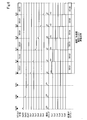
- FIG. 2 is a time chart showing the power supply start timing of each power supply segment.
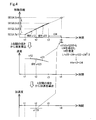
- FIG. 3 is a first explanatory diagram showing the estimation of the power supply start timing.
- FIG. 4 is a second explanatory diagram showing the estimation of the power supply start timing.
- FIG. 5 is an explanatory diagram showing the overall configuration of the vehicle power supply system of the second embodiment.
- FIG. 6 is a time chart showing the power supply start timing of each power supply segment.
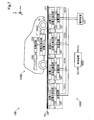
- FIG. 7 is an explanatory diagram showing an application form of the vehicle power supply system of the first embodiment.
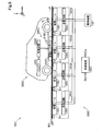
- FIG. 8 is an explanatory diagram showing another application of the vehicle power supply system of the first embodiment.
- the power supply device 100 is provided to the vehicle 200 passing through the power supply lane LF from the power supply device 100 laid in the power supply lane LF along the track of the vehicle travel path RS.
- This is a power supply system capable of supplying electric power in a non-contact state or a contact state between the power transmission unit and the power reception unit of the vehicle 200.
- the vehicle 200 is configured as, for example, an electric vehicle, a hybrid vehicle, a fuel cell vehicle, or the like.
- the x direction indicates the traveling direction of the vehicle 200 along the traveling path of the vehicle traveling path RS
- the y direction indicates the width direction of the vehicle traveling path RS
- the z direction indicates the vertical upward direction.
- the directions of x, y, and z in other figures described later also show the same directions as in FIG.
- the vehicle 200 includes a power receiving device 205 including a power receiving unit (not shown) and a power receiving circuit.
- the power receiving unit is a circuit block that receives power from the power feeding segment SEG, which will be described later, in contact or non-contact
- the power receiving circuit is a circuit block that converts the received power into power that can be used internally.
- the vehicle 200 also supplies power to the control device that controls the power receiving device 205, the battery that stores the received power, the motor generator, and the motor generator when the motor generator generates power, and the motor generator supplies the power.
- an inverter circuit or the like for supplying the generated electric power to the battery is provided, but the illustration is omitted.
- the power supply device 100 includes a plurality of power supply segment SEGs, a power supply device 130 that supplies DC power to the plurality of power supply segment SEGs, and a control device 140 that controls the operation of the plurality of power supply segment SEGs.
- Each power supply segment SEG includes a power transmission circuit and a power transmission unit (not shown).
- the power transmission unit is a circuit block that supplies electric power in contact or non-contact with the power receiving unit included in the power receiving device 205 of the vehicle 200
- the power transmission circuit is a circuit block that outputs the supplied electric power to the power transmission unit. ..
- Each power feeding segment SEG is laid at equal intervals in the power feeding lane LF in order along the x direction at a laying interval L.
- FIG. 1 shows an example in which six power supply segments SEG1 to SEG6 are laid at the front side in the traveling direction (x direction) of the power supply lane LF.
- the number is not limited to this, and the number of power supply segment SEGs laid in the power supply lane LF may be 3 or more, more preferably 4 or more.
- the front side (-x direction side) of the power feeding lane LF in the traveling direction (x direction) is treated as the "front side”
- the back side (+ x direction side) is treated as the "rear side”.
- Receiving sensors Sr are laid at the front ends of each power feeding segment SEG. That is, each receiving sensor Sr is laid in order along the x direction at the laying interval L.
- a transmitter St is mounted on the bottom surface of the front end of the vehicle 200 so as to face the receiving sensor Sr. By receiving the output signal of the transmitter St, each receiving sensor Sr can detect that the vehicle 200 has reached the position of the received receiving sensor Sr.
- the reception output Dp (Dp1 to Dp6 in this example) from the reception sensor Sr of each power supply segment SEG is input to the control device 140. Thereby, it is possible to detect which of the receiving sensors Sr of each feeding segment SEG has received the output from the transmitter St, and it is possible to detect which position of the feeding lane LF the vehicle 200 is in.
- a transmitting coil As a transmitter, a transmitting coil, LD (laser diode), LED (light emitting diode), etc. can be used, and as a receiving sensor, a receiving coil, a photodiode as a light receiving element, etc., depending on the type of transmitter, etc. Is available.
- LD laser diode
- LED light emitting diode
- the control device 140 estimates the timing at which power supply is started for each power supply segment SEG based on the reception output Dp input from each reception sensor Sr, and the control signal Ce of each power supply segment SEG. (Ce1 to Ce6 in this example) is output to each power feeding segment SEG. As a result, the control device 140 controls the start timing of feeding of each feeding segment SEG.
- the control device 140 is configured by using, for example, a microcomputer or the like.
- the operation of the power transmission circuit is activated from the instruction to start the power supply to the instruction to end the power supply by the control signal Ce supplied from the control device 140, and the power is transmitted from the power transmission circuit to the power transmission unit. Output is performed, and power is supplied to the power receiving device 205 via the power transmitting unit and the power receiving unit.
- the reception sensors Sr1 to Sr6 of the power supply segments SEG1 to SEG6 move the output from the transmitter St of the vehicle 200 to the vehicle 200 as shown in FIG.
- the reception outputs Dp1 to Dp6 are output to the control device 140 in order according to the above.
- the control device 140 detects the timing indicating that the front end of each power feeding segment SEG1 to SEG6 has been reached according to the received outputs Dp1 to DP6.
- FIG. 2 shows the detection timings of the power supply segments SEG1 to SEG6 as times t1 to t6.
- the control device 140 derives the average speed and acceleration of the vehicle 200 according to each detection timing, and the derived average speed and acceleration are set as the initial speed and acceleration of the uniform acceleration linear motion, and the vehicle 200 is next.
- the time when the front end of the power supply segment SEG is reached, that is, the timing of the start of power supply is estimated.
- the passage of the front end of the first power supply segment SEG1 of the vehicle 200 is detected at time t1 by the detection of the first reception sensor Sr1, and the passage of the front end of the first power supply segment SEG1 of the vehicle 200 is detected by the detection of the second reception sensor Sr2 at time t2.
- the state in which the passage of the front end of the second power feeding segment SEG2 of the vehicle 200 is detected is shown. That is, the upper part of FIG. 3 shows a state in which the current power supply segment in which the vehicle 200 is passing and power supply is being executed is the second power supply segment SEG2, and the next power supply segment is the third power supply segment SEG3.
- the control device 140 Even if the control device 140 detects the time t1 as the detection timing of the first power supply segment SEG1 from the reception output Dp1 of the first reception sensor Sr, the above-mentioned average speed and acceleration cannot be derived. Therefore, as shown in FIG. 2, the control device 140 starts feeding the first feeding segment SEG1 with the time t1 as the detection timing and the control signal Ce1 for the first feeding segment SEG1 as active (H level). .. Similarly, the control device 140 cannot derive the above-mentioned average speed and acceleration from the reception output Dp2 of the second reception sensor Sr2 until the time t2 is detected as the detection timing of the second power supply segment SEG2. Therefore, as shown in FIG.
- the control device 140 stops the feeding of the first feeding segment SEG1 by setting the time t2 as the detection timing and setting the control signal Ce1 for the first feeding segment SEG1 as inactive (L level). Then, the control signal Ce2 for the second power supply segment SEG2 is activated to start the power supply of the second power supply segment SEG2. In this way, in the first and second power supply segments SEG1 and SEG2, the start and stop of power supply are controlled with the times t1 and t2 as detection timings, so that the timing at which power supply is actually started for the vehicle 200 is determined. It will be slow and there will be wasted time when power cannot be supplied.
- the control device 140 moves from time t1 to time t2 as shown in the upper part of FIG.
- the control device 140 derives the acceleration a012 between the two points from the slope between the two points of the average velocity.
- the acceleration a012 cannot be derived, and the acceleration a012 in this case is set to “0”.
- the control device 140 sets the time t3 (see the upper part of FIG. 3), which is the time to reach the front end of the third power supply segment SEG3, which is the next power supply segment, and the timing to start power supply, as follows.
- the motion of the vehicle 200 during the movement time t23 from the second power supply segment SEG2 to the third power supply segment SEG3 is treated as a uniform acceleration linear motion, and the derived average velocity v12 and acceleration a012 are treated as the constant acceleration linear motion.
- the moving distance L of the vehicle 200 is expressed by the following equation (1) from the displacement formula of the constant acceleration linear motion.
- the control device 140 immediately deactivates the control signal Ce2 for the second power supply segment SEG2 and immediately activates the control signal Ce3 for the third power supply segment SEG3 at the estimated time t3e. , Can be controlled to immediately start feeding the third feeding segment SEG3.
- the delay in the start timing of the third power feeding segment can be improved.
- the estimated time t3e since the time t3 is estimated with the acceleration of the vehicle 200 as 0, the estimated time t3e does not reflect the acceleration / deceleration of the vehicle 200, but the speed of the vehicle 200. Is reflected.
- the error of the estimated time t3e is larger than that of the case where the time is estimated from the speed and acceleration of the vehicle with respect to the time t3, but the actual time is like the first and second power supply segments SEG1 and SEG2.
- the delay of the start timing can be improved.
- the upper part of FIG. 4 shows a state in which the current power supply segment through which the vehicle 200 is passing is the third power supply segment SEG3, and the next power supply segment is the fourth power supply segment SEG4.
- the control device 140 moves from time t2 to time t3 as shown in the upper part of FIG.
- the slope v23 of the distance L By obtaining the slope v23 of the distance L, the average velocity v23 between the two points is derived as shown in the middle part of FIG. Further, the control device 140 obtains the slope a123 between the two points of the average speed of the first average speed v12 and the second average speed v23, thereby obtaining the acceleration a123 between the two points as shown in the lower part of FIG. Derived.
- the control device 140 sets the time t4 (see the upper part of FIG. 4), which is the time when the control device 140 reaches the front end of the fourth power supply segment SEG4, which is the next power supply segment, and is the timing when the power supply is started, as follows.
- the motion of the vehicle 200 during the movement time t34 from the third power supply segment SEG3 to the fourth power supply segment SEG4 is treated as a uniform acceleration linear motion, and the derived average velocity v23 and acceleration a123 are treated as the constant acceleration linear motion.
- the moving distance L of the vehicle 200 is expressed by the following equation (4) from the displacement formula of the constant acceleration linear motion.
- L v23 ⁇ t34 + a123 ⁇ t34 2/2 ⁇ (4)
- the control device 140 immediately deactivates the control signal Ce3 for the third power supply segment SEG3 and immediately activates the control signal Ce4 for the fourth power supply segment SEG4 at the estimated time t4e. , Can be controlled to immediately start feeding the fourth feeding segment SEG4.
- the fourth and subsequent power supply segments SEG5 and SEG6 it is possible to control the timing of starting power supply in the same procedure as the estimation of the timing of starting the power supply of the fourth power supply segment SEG4. Therefore, as shown in FIG. 2, the delay of the start timing of the fourth and subsequent power supply segments can be further improved as compared with the delay improvement of the start timing of the third power supply segment.
- an appropriate timing is obtained by estimating the time when the vehicle 200 reaches the next power supply segment SEG, that is, the timing at which power supply is started, from the speed or speed and acceleration of the vehicle 200. Can control the start of power supply by the next power supply segment. It is possible to suppress the occurrence of wasted time during which power cannot be supplied to the vehicle 200 due to a delay in the timing at which power is actually started.
- the power supply device 100A of the vehicle power supply system 10A of the second embodiment shown in FIG. 5 has six reception sensors Sr1 to Sr6 on the front side of the power supply lane LF of the vehicle power supply system 10 (see FIG. 1) of the first embodiment. The difference is that three reception sensors Sr01 to Sr03 are laid at the same laying interval L, and the control device 140A is provided instead of the control device 140.
- the control operation of the control device 140A is performed at the position of the vehicle 200 by using not only the reception outputs Dp1 to Dp6 of the reception sensors Sr1 to Sr6 of each power supply segment SEG1 to SEG6 but also the reception outputs Dp01 to Dp03 of the reception sensors Sr01 to Sr03. It is the same as the control operation of the control device 140 except that the detection is performed.
- the three reception sensors Sr03 to Sr01 on the front side of the first power supply segment SEG1 also receive the outputs from the transmitter St (see FIG. 5) of the vehicle 200 in order according to the movement of the vehicle 200.
- the reception outputs Dp03 to Dp01 are output to the control device 140A in the same manner as the reception outputs Dp1 to Dp6 of the other reception sensors Sr1 to Sr6.
- the control device 140 detects that it has reached the front end of the dummy power feeding segment according to the received outputs Dp03 to Dp01. Note that FIG. 6 shows the detection timing of the dummy power feeding segment as times t03 to t01.
- the control device 140A has a time t03, which is the detection timing by the reception sensor Sr03 three times before, a time t02, which is the detection timing by the reception sensor Sr02 two times before, and a reception sensor one before.
- the time t01 which is the detection timing by Sr01, is detected.
- the control device 140A can derive the average speed between the time t03 and the time t02 and the average speed between the time t02 and the time t01, and derive the acceleration from the average speed of the two derived points. Can be done.
- control device 140A sets the average velocity and acceleration between the derived time t02 and time t01 as the initial velocity and acceleration of the uniform acceleration linear motion, so that the vehicle 200 reaches the front end of the first power feeding segment SEG1. It is possible to estimate the estimated time t1e at the time t1 to be performed (see FIG. 4).
- the control device 140A is controlled to immediately activate the control signal Ce1 for the first power supply segment SEG1 at the estimated time t1e and immediately start the power supply of the first power supply segment SEG1. can do.
- the second and subsequent power supply segments SEG2 to SEG6 it is possible to control the timing of starting power supply in the same procedure as the estimation of the timing of starting power supply of the first power supply segment SEG1. Therefore, as shown in FIG. 6, it is possible to improve the delay of the start timing of all the power feeding segments, and it is possible to improve the delay more effectively than in the first embodiment.
- the vehicle power supply system 10 of the first embodiment can be applied as the non-contact power supply system 10B for the vehicle shown in FIG. 7.
- the power transmission unit of the power feeding device 100B and the vehicle 200B are connected to the vehicle 200B passing through the power feeding lane LF. It is a vehicle power supply system that can supply electric power without contact with the power receiving unit.
- the power supply device 100B includes a plurality of power supply segment SEGs (SEG1 to SEG4 in the example of the figure), a power supply device 130 that supplies DC power to the plurality of power supply segment SEGs, and a plurality of power supply segment SEGs. It includes a control device 140B for controlling the operation.
- Each power supply segment SEG includes a power transmission circuit 120, a power transmission resonance circuit 110, and a reception sensor Sr.
- the power transmission resonance circuit 110 has a power transmission coil 112 installed on the power supply lane LF and a resonance capacitor (not shown).
- the power transmission coil 112 and the reception sensor Sr of each power supply segment SEG are laid at equal intervals in order along the x direction on the power supply lane LF.
- the power transmission circuit 120 is a circuit that converts the DC power supplied from the power supply device 130 into high-frequency AC power and supplies it to the power transmission coil 112 that transmits the power to the vehicle 200B.
- the power transmission circuit 120 is configured as, for example, an inverter circuit, and the operating state (power supply) and the non-operating state (non-power supply) are controlled according to the control signal Ce from the control device 140B.
- the power supply device 130 is configured as, for example, an AC / DC converter circuit that rectifies the AC voltage of the external power supply and outputs a DC voltage.
- the vehicle 200B includes a power receiving resonance circuit 210, a power receiving circuit 220, and a battery 230, which are power receiving units, as the power receiving device 205B. Further, the vehicle 200B has a transmitter St mounted on the bottom surface of the front end so as to face the receiving sensor Sr.
- the power receiving resonance circuit 210 includes a power receiving coil 212 installed at the bottom of the vehicle 200B on the center side in the front-rear direction and a resonance capacitor (not shown), and the power receiving coil 212 is caused by a magnetic field coupling phenomenon between the power transmission resonance circuit 110. It is a device that obtains the AC power induced in.
- the power receiving circuit 220 is a circuit that converts the AC power obtained by the power receiving resonance circuit 210 into DC power and charges the battery 230 as a load.
- the electric power charged in the battery 230 is used to drive a motor or the like (not shown).
- the control device 140B is the same as the control device 140 of the vehicle power supply system 10 (see FIG. 1) of the first embodiment, and each power supply segment is based on the reception output Dp input from the reception sensor Sr of each power supply segment SEG. For each SEG, the timing to start feeding is estimated, and the control signal Ce of each feeding segment SEG is output to each feeding segment SEG. As a result, the control device 140B controls the start timing of feeding of each feeding segment SEG.
- the non-contact power supply system 10B for this vehicle can also obtain the same effect as the vehicle power supply system 10 of the first embodiment.
- the vehicle power supply system 10A (see FIG. 5) of the second embodiment is used as the non-contact power supply system for vehicles, similarly to the non-contact power supply system 10B for vehicles (see FIG. 7). It is also possible to apply.
- the vehicle power supply system 10 of the first embodiment can be applied as the contact power supply system 10C for a vehicle shown in FIG.
- the power transmission unit of the power supply device 100C and the vehicle 200C receive power from the power supply device 100C laid in the power supply lane LF along the track of the vehicle travel path RS to the vehicle 200C passing through the power supply lane LF. It is a vehicle power supply system that can supply electric power in contact with the unit.
- the power supply device 100C includes a plurality of power supply segment SEGs (SEG1 to SEG4 in the example of the figure), a power supply device 130 that supplies DC power to the plurality of power supply segment SEGs, and a plurality of power supply segment SEGs. It includes a control device 140C for controlling the operation.
- Each power supply segment SEG includes a power supply rail 110C, a power transmission circuit 120C, and a reception sensor Sr.
- the power supply rail 110C is a pair of electrodes laid in parallel on the power supply lane LF.
- the power supply rails 110C and the reception sensor Sr of each power supply segment SEG are laid at equal intervals in order along the x direction on the power supply lane LF.
- the power transmission circuit 120C is a circuit that supplies DC power supplied from the power supply device 130 to the power supply rail 110C.
- the power transmission circuit 120C is configured as, for example, a switch circuit.
- the vehicle 200C includes a power receiving pickup 210C, a power receiving circuit 220C, and a battery 230, which are power receiving units, as the power receiving device 205C. Further, the vehicle 200C is equipped with a transmitter St on the bottom surface of the front end so as to face the receiving sensor Sr.
- the power receiving pickup 210C is supported by the arm 218C at the bottom of the vehicle 200C in the front-rear direction on the center side so as to come into contact with the power feeding rail 110C when receiving power from the power feeding device 100C.
- the power receiving pickup 210C has a pair of electrodes provided so as to face the pair of electrodes of the power feeding rail 110C, and is a device that obtains DC power from the power feeding rail 110C by coming into contact with the power feeding rail 110C.
- the power receiving circuit 220C is a circuit for charging the battery 230 with the DC power obtained by the power receiving resonance circuit 210 obtained by the power receiving pickup 210C.
- the electric power charged in the battery 230 is used to drive a motor or the like (not shown).
- the control device 140C is the same as the control device 140 of the vehicle power supply system 10 (see FIG. 1) of the first embodiment, and each power supply segment is based on the reception output Dp input from the reception sensor Sr of each power supply segment SEG. For each SEG, the timing to start feeding is estimated, and the control signal Ce of each feeding segment SEG is output to each feeding segment SEG. As a result, the control device 140C controls the start timing of feeding of each feeding segment SEG.
- the contact power supply system 10C for the vehicle can also obtain the same effect as the vehicle power supply system 10 of the first embodiment.
- the vehicle power supply system 10A (see FIG. 5) of the second embodiment is applied as the contact power supply system for vehicles in the same manner as the contact power supply system 10C for vehicles (see FIG. 8). It is also possible.
- the reception sensor Sr installed in each power supply segment SEG receives the output from the transmitter St mounted on the vehicle to detect that the vehicle has reached each power supply segment SEG.
- the vehicle may be configured without a transmitter.
- a sensor having a transmitter and a receiving sensor as a receiving sensor, the arrival of the vehicle is detected by receiving the signal reflected by the vehicle from the signal output from its own transmitter by the receiving sensor. It may be. Further, a camera may be used as a receiving sensor to detect the arrival of the vehicle from the captured image.
- a weight scale may be laid at the position of the receiving sensor Sr to detect the arrival or passage of the vehicle by the weight change.
- the reception sensors Sr1 to Sr6 of the power supply segments SEG1 to SEG6 laid in the power supply lane LF and the reception sensors Sr01 to Sr03 laid in front of the power supply lane LF are set in advance. Although they are laid at equal intervals at the laying intervals L, they do not necessarily have to be laid at equal intervals.
- the reception sensors Sr1 to Sr6 of the power supply segments SEG1 to SEG6 of the power supply lane LF and the reception sensors Sr01 to Sr03 on the front side of the power supply lane LF are laid at preset intervals, and information on each interval is provided. Is stored in the control devices 140, 140A to 140C in advance and is known.
- the controls and methods thereof described in the present disclosure are realized by a dedicated computer provided by configuring a processor and memory programmed to perform one or more functions embodied by a computer program. May be done.
- the controls and methods thereof described in the present disclosure may be implemented by a dedicated computer provided by configuring the processor with one or more dedicated hardware logic circuits.
- the control unit and method thereof described in the present disclosure may be a combination of a processor and memory programmed to perform one or more functions and a processor composed of one or more hardware logic circuits. It may be realized by one or more dedicated computers configured.
- the computer program may be stored in a computer-readable non-transitional tangible recording medium as an instruction executed by the computer.
- the present disclosure is not limited to the above-described embodiment, and can be realized with various configurations within a range not deviating from the purpose.
- the technical features in the embodiments corresponding to the technical features in each form described in the column of the outline of the invention may be used to solve some or all of the above-mentioned problems, or one of the above-mentioned effects. It is possible to replace or combine as appropriate to achieve part or all. Further, if the technical feature is not described as essential in the present specification, it can be deleted as appropriate.
Landscapes
- Engineering & Computer Science (AREA)
- Power Engineering (AREA)
- Computer Networks & Wireless Communication (AREA)
- Mechanical Engineering (AREA)
- Transportation (AREA)
- Life Sciences & Earth Sciences (AREA)
- Sustainable Development (AREA)
- Sustainable Energy (AREA)
- Electric Propulsion And Braking For Vehicles (AREA)
- Charge And Discharge Circuits For Batteries Or The Like (AREA)
- Current-Collector Devices For Electrically Propelled Vehicles (AREA)
Abstract
車両走行路(RS)の給電レーン(LF)に敷設された給電装置(100)から車両(200)に対して給電を行なう車両給電システム(10)の給電装置は、給電レーンに沿って、予め設定された間隔で敷設された複数の給電セグメント(SEG)と、複数の給電セグメントを制御する制御装置(140)とを備える。制御装置は、給電が行なわれる現在給電セグメントの次に給電が行なわれる次期給電セグメントに前記車両が到達するタイミングを、少なくとも、車両の位置の変化から導出される車両の速度から推定し、推定したタイミングで次期給電セグメントによる給電を開始させる。
Description
本願は、その全ての開示が参照によりここに組み込まれる、2019年9月18日に出願された出願番号2019-169169の日本国特許出願に基づく優先権を主張する。
本開示は、電力によって走行可能な車両に対して給電を行なう技術に関する。
特開2018-57073号公報には、走行中の車両が給電レーンを外れる場合のバッテリの充電不足を防止する技術が開示されている。
ここで、走路に沿って敷設された複数の給電ユニットのそれぞれから車両に給電を開始する適切なタイミングは、車両の加減速に応じて変化するが、従来技術においては、この変化について十分な検討がなされていない。
本開示の一形態によれば、車両走行路の給電レーンに敷設された給電装置から車両に対して給電を行なう車両給電システムが提供される。この車両給電システムの前記給電装置は、前記給電レーンに沿って、予め設定された間隔で敷設された複数の給電セグメントと、前記複数の給電セグメントを制御する制御装置と、を備える。前記制御装置は、給電が行なわれる現在給電セグメントの次に給電が行なわれる次期給電セグメントに前記車両が到達するタイミングを、少なくとも、前記車両の位置の変化から導出される前記車両の速度から推定し、推定したタイミングで前記次期給電セグメントによる給電を開始させる。
この形態の車両給電システムによれば、車両の加減速に応じて、適切なタイミングで給電セグメントから車両への給電を開始することができる。
この形態の車両給電システムによれば、車両の加減速に応じて、適切なタイミングで給電セグメントから車両への給電を開始することができる。
本開示についての上記目的およびその他の目的、特徴や利点は、添付の図面を参照しながら下記の詳細な記述により、より明確になる。その図面は、
図1は第1実施形態の車両給電システムの全体構成を示す説明図、
図2は各給電セグメントの給電開始タイミングについて示すタイムチャート、
図3は給電開始タイミングの推定について示す第1の説明図、
図4は給電開始タイミングの推定について示す第2の説明図、
図5は第2実施形態の車両給電システムの全体構成を示す説明図、
図6は各給電セグメントの給電開始タイミングについて示すタイムチャート、
図7は第1実施形態の車両給電システムの適用形態を示す説明図、
図8は第1実施形態の車両給電システムの別の適用形態を示す説明図。
A.第1実施形態:
図1に示すように、車両給電システム10は、車両走行路RSの走路に沿った給電レーンLFに敷設された給電装置100から、給電レーンLFを通過する車両200に対して、給電装置100の送電部と車両200の受電部とが非接触な状態あるいは接触した状態で電力を供給することが可能な給電システムである。車両200は、例えば、電気自動車やハイブリッド車、燃料電池車等として構成される。図1において、x方向は車両走行路RSの走路に沿った車両200の進行方向を示し、y方向は車両走行路RSの幅方向を示し、z方向は垂直上方向を示す。後述する他の図におけるx,y,zの方向も、図1と同じ方向を示している。
図1に示すように、車両給電システム10は、車両走行路RSの走路に沿った給電レーンLFに敷設された給電装置100から、給電レーンLFを通過する車両200に対して、給電装置100の送電部と車両200の受電部とが非接触な状態あるいは接触した状態で電力を供給することが可能な給電システムである。車両200は、例えば、電気自動車やハイブリッド車、燃料電池車等として構成される。図1において、x方向は車両走行路RSの走路に沿った車両200の進行方向を示し、y方向は車両走行路RSの幅方向を示し、z方向は垂直上方向を示す。後述する他の図におけるx,y,zの方向も、図1と同じ方向を示している。
車両200は、不図示の受電部と受電回路を含む受電装置205を備えている。受電部は、後述する給電セグメントSEGから接触あるいは非接触で電力の供給を受ける回路ブロックであり、受電回路は受電した電力を内部で利用可能な電力に変換する回路ブロックである。なお、車両200は、その他、受電装置205を制御する制御装置や、受電した電力を蓄電するバッテリ、モータジェネレータ、モータジェネレータが動力を発生する場合にはモータジェネレータに電力を供給し、モータジェネレータが電力を発生する場合には発生した電力をバッテリに供給するインバータ回路等を備えるが、図示は省略する。
給電装置100は、複数の給電セグメントSEGと、複数の給電セグメントSEGに直流電力を供給する電源装置130と、複数の給電セグメントSEGの動作を制御する制御装置140と、を備えている。
各給電セグメントSEGは、不図示の送電回路および送電部を備えている。送電部は、車両200の受電装置205に含まれる受電部との間で接触あるいは非接触で電力の供給を行なう回路ブロックであり、送電回路は供給する電力を送電部に出力する回路ブロックである。各給電セグメントSEGは、給電レーンLFにおいて、x方向に沿って順に敷設間隔Lで等間隔に敷設されている。
なお、図1は、給電レーンLFの進行方向(x方向)の手前側を先頭に6つの給電セグメントSEG1~SEG6が敷設されている例が示されている。但し、これに限定されるものではなく、給電レーンLFに敷設される給電セグメントSEGの数は3以上、より好ましくは4以上であれば良い。なお、以下では、給電レーンLFの進行方向(x方向)の手前側(-x方向側)を「前側」、奥側(+x方向側)を「後側」として扱う。
各給電セグメントSEGの前端には、それぞれ、受信センサSr(本例では、Sr1~Sr6)が敷設されている。すなわち、各受信センサSrは敷設間隔Lでx方向に沿って順に敷設されている。一方、車両200の前端の底面には、受信センサSrと向き合うように、送信器Stが搭載されている。各受信センサSrは、送信器Stの出力信号を受信することにより、受信した受信センサSrの位置に車両200が到達したことを検知することができる。各給電セグメントSEGの受信センサSrからの受信出力Dp(本例ではDp1~Dp6)は、制御装置140に入力される。これにより、各給電セグメントSEGの受信センサSrのいずれが送信器Stからの出力を受信したか検出することができ、車両200が給電レーンLFのいずれの位置にあるかを検出することができる。
なお、送信器としては、送信コイルやLD(レーザダイオード)、LED(発光ダイオード)等が利用可能であり、受信センサとしては、送信器の種類に応じて受信コイルや受光素子としてのフォトダイオード等が利用可能である。
制御装置140は、後述するように、各受信センサSrから入力された受信出力Dpに基づいて、各給電セグメントSEGについて、それぞれ、給電を開始するタイミングを推定し、各給電セグメントSEGの制御信号Ce(本例ではCe1~Ce6)を各給電セグメントSEGに出力する。これにより、制御装置140は、各給電セグメントSEGの給電の開始タイミングを制御する。なお、制御装置140は、例えば、マイクロコンピュータ等を用いて構成される。各給電セグメントSEGでは、制御装置140から供給される制御信号Ceによって給電の開始が指示されてから給電の終了が指示されるまで送電回路の動作が活性化され、送電回路から送電部へ電力の出力が行なわれ、送電部及び受電部を介して受電装置205への給電を行なわれる。
車両200が給電レーンLF(図1参照)を移動すると、各給電セグメントSEG1~SEG6の受信センサSr1~Sr6は、図2に示すように、車両200の送信器Stからの出力を車両200の移動に従って順に受信し、受信出力Dp1~Dp6を制御装置140に出力する。制御装置140は、図2に示すように、受信出力Dp1~DP6に従って、各給電セグメントSEG1~SEG6の前端に到達したことを示すタイミングを検出する。なお、図2には、各給電セグメントSEG1~SEG6の検出タイミングを時刻t1~t6として示している。
制御装置140は、各検出タイミングに従って、以下で説明するように、車両200の平均速度および加速度を導出し、導出した平均速度及び加速度を等加速度直線運動の初速度及び加速度として、車両200が次の給電セグメントSEGの前端に到達する時刻、すなわち、給電開始のタイミングを推定する。
図3の上段には、1番目の受信センサSr1の検出により、時刻t1で車両200の1番目の給電セグメントSEG1の前端の通過が検出され、2番目の受信センサSr2の検出により、時刻t2で車両200の2番目の給電セグメントSEG2の前端の通過が検出された状態が示されている。すなわち、図3の上段は、車両200が通過中で給電実行中の現在給電セグメントは2番目の給電セグメントSEG2であり、次期給電セグメントは3番目の給電セグメントSEG3である状態を示している。
制御装置140は、1番目の受信センサSrの受信出力Dp1から1番目の給電セグメントSEG1の検出タイミングとして時刻t1を検出しても、上述した平均速度及び加速度を導出することはできない。このため、制御装置140は、図2に示すように、時刻t1を検出タイミングとして、1番目の給電セグメントSEG1に対する制御信号Ce1をアクティブ(Hレベル)として1番目の給電セグメントSEG1の給電を開始させる。同様に、制御装置140は、2番目の受信センサSr2の受信出力Dp2から2番目の給電セグメントSEG2の検出タイミングとして時刻t2を検出するまで、上述した平均速度および加速度を導出することはできない。このため、制御装置140は、図2に示すように、時刻t2を検出タイミングとして、1番目の給電セグメントSEG1に対する制御信号Ce1を非アクティブ(Lレベル)として1番目の給電セグメントSEG1の給電を停止させ、2番目の給電セグメントSEG2に対する制御信号Ce2をアクティブとして2番目の給電セグメントSEG2の給電を開始させる。このように、1番目及び2番目の給電セグメントSEG1,SEG2では、時刻t1,t2を検出タイミングとして給電の開始及び停止が制御されるので、車両200に対して実際に給電が開始されるタイミングが遅くなり、給電できない無駄な時間が発生する。
そして、時刻t2で車両200が2番目の給電セグメントSEG2の前端を通過したことが検出された場合(図2参照)、制御装置140は、図3の上段に示すように時刻t1から時刻t2までの移動距離Lの傾きv12を求めることにより、図3の中段に示すように2点間の平均速度v12を導出する。また、制御装置140は、平均速度の2点間の傾きから2点間の加速度a012を導出する。但し、時刻t2では、図3の中段に示すように、1点の平均速度v12しか導出されないので、加速度a012を導出することはできず、この場合の加速度a012は「0」とされる。
ここで、制御装置140は、次期給電セグメントである3番目の給電セグメントSEG3の前端に到達する時刻であって、給電を開始するタイミングである時刻t3(図3の上段参照)を、以下のように推定する。すなわち、2番目の給電セグメントSEG2から3番間の給電セグメントSEG3までの移動時間t23の間の車両200の運動を等加速度直線運動として扱い、導出した平均速度v12及び加速度a012を等加速度直線運動の初速度及び加速度と推定する。この場合、車両200の移動距離Lは、等加速度直線運動の変位の公式から、下式(1)のように表される。ただし、ここでは、a012=0であるので、車両200の運動は等速直線運動として扱い、移動距離Lは下式(2)で表される。
L=v12・t23+a012・t232/2 ・・・(1)
=v12・t23 ・・・(2)
L=v12・t23+a012・t232/2 ・・・(1)
=v12・t23 ・・・(2)
制御装置140は、上式(2)から移動時間t23を求めることにより、下式(3)に示すように、3番目の給電セグメントSEG3の前端に車両200が到達する時刻t3を、予め、推定時刻t3eとして導出することができる。
t3e=t2+t23 ・・・(3)
t3e=t2+t23 ・・・(3)
これにより、制御装置140は、図2に示すように、推定時刻t3eで、2番目の給電セグメントSEG2に対する制御信号Ce2を直ちに非アクティブとし、3番目の給電セグメントSEG3に対する制御信号Ce3を直ちにアクティブとして、直ちに3番目の給電セグメントSEG3の給電を開始させるように制御することができる。これにより、図2に示すように、3番目の給電セグメントの開始タイミングの遅延を改善することができる。但し、この場合には、上記したように、車両200の加速度を0として時刻t3を推定しているので、推定時刻t3eには、車両200の加減速が反映されていないが、車両200の速度は反映されている。従って、車両の速度および加速度から時刻が推定される場合に比べて、推定時刻t3eは時刻t3に対して誤差は大きくなるが、1番目,2番目の給電セグメントSEG1,SEG2のように、実際の検出タイミングをトリガとして給電の開始を制御する場合に比べて、開始タイミングの遅延を改善することができる。
次に、図4の上段には、図3の上段に引き続き、3番目の受信センサSr3の検出により、時刻t3で車両200の3番目の給電セグメントSEG1の前端の通過が検出された状態が示されている。すなわち、図4の上段は、車両200が通過中の現在給電セグメントは3番目の給電セグメントSEG3であり、次期給電セグメントは4番目の給電セグメントSEG4である状態を示している。
時刻t3で車両200が3番目の給電セグメントSEG3の前端を通過したことが検出された場合(図2参照)、制御装置140は、図4の上段に示すように時刻t2から時刻t3までの移動距離Lの傾きv23を求めることにより、図4の中段に示すように2点間の平均速度v23を導出する。また、制御装置140は、1番目の平均速度v12と2番目の平均速度v23の平均速度の2点間の傾きa123を求めることにより、図4の下段に示すように2点間の加速度a123を導出する。
ここで、制御装置140は、次期給電セグメントである4番目の給電セグメントSEG4の前端に到達する時刻であって、給電を開始するタイミングである時刻t4(図4の上段参照)を、以下のように推定する。すなわち、3番目の給電セグメントSEG3から4番間の給電セグメントSEG4までの移動時間t34の間の車両200の運動を等加速度直線運動として扱い、導出した平均速度v23及び加速度a123を等加速度直線運動の初速度及び加速度と推定する。この場合、車両200の移動距離Lは、等加速度直線運動の変位の公式から、下式(4)のように表される。
L=v23・t34+a123・t342/2 ・・・(4)
L=v23・t34+a123・t342/2 ・・・(4)
制御装置140は、上式(4)から移動時間t34を求めることにより、下式(5)に示すように、4番目の給電セグメントSEG4の前端に車両200が到達する時刻t4を、予め、推定時刻t4eとして導出することができる。
t4e=t3+t34 ・・・(5)
t4e=t3+t34 ・・・(5)
これにより、制御装置140は、図2に示すように、推定時刻t4eで、3番目の給電セグメントSEG3に対する制御信号Ce3を直ちに非アクティブとし、4番目の給電セグメントSEG4に対する制御信号Ce4を直ちにアクティブとして、直ちに4番目の給電セグメントSEG4の給電を開始させるように制御することができる。4番目以降の給電セグメントSEG5,SEG6においても、4番目の給電セグメントSEG4の給電を開始するタイミングの推定と同様の手順で給電を開始するタイミングを制御することができる。従って、図2に示すように、4番目以降の給電セグメントの開始タイミングの遅延を3番目の給電セグメントの開始タイミングの遅延改善よりもさらに改善することができる。
以上説明したように、車両給電システム10では、車両200が次期給電セグメントSEGに到達する時刻、すなわち、給電を開始するタイミングを、車両200の速度あるいは速度および加速度から推定することにより、適切なタイミングで次期給電セグメントによる給電の開始を制御することができる。車両200に対して実際に給電が開始されるタイミングが遅くなって給電できない無駄な時間が発生することを抑制することができる。
B.第2実施形態:
図5に示す第2実施形態の車両給電システム10Aの給電装置100Aは、第1実施形態の車両給電システム10(図1参照)の給電レーンLFの手前側に、6つの受信センサSr1~Sr6と同じ敷設間隔Lで、3つの受信センサSr01~Sr03が敷設されており、制御装置140に変えて制御装置140Aを備えている点が異なっている。
図5に示す第2実施形態の車両給電システム10Aの給電装置100Aは、第1実施形態の車両給電システム10(図1参照)の給電レーンLFの手前側に、6つの受信センサSr1~Sr6と同じ敷設間隔Lで、3つの受信センサSr01~Sr03が敷設されており、制御装置140に変えて制御装置140Aを備えている点が異なっている。
制御装置140Aの制御動作は、各給電セグメントSEG1~SEG6の受信センサSr1~Sr6の受信出力Dp1~Dp6だけでなく、受信センサSr01~Sr03の受信出力Dp01~Dp03も用いて、車両200の位置の検出を行なっている点を除いて、制御装置140の制御動作と同じである。
図6に示すように、1番目の給電セグメントSEG1よりも手前側の3つの受信センサSr03~Sr01も、車両200の送信器St(図5参照)からの出力を車両200の移動に従って順に受信し、受信出力Dp03~Dp01を、他の受信センサSr1~Sr6の受信出力Dp1~Dp6と同様に、制御装置140Aに出力する。制御装置140は、図6に示すように、受信出力Dp03~Dp01に従って、ダミーの給電セグメントの前端に到達したことを検出する。なお、図6には、ダミーの給電セグメントの検出タイミングを時刻t03~t01として示している。
制御装置140Aは、図6に示すように、三つ前の受信センサSr03による検出タイミングである時刻t03と、二つ前の受信センサSr02による検出タイミングである時刻t02と、一つ前の受信センサSr01による検出タイミングである時刻t01と、を検出する。これにより、制御装置140Aは、時刻t03から時刻t02の間の平均速度と、時刻t02から時刻t01の間の平均速度を導出することができ、導出した2点の平均速度から加速度を導出することができる。そして、制御装置140Aは、導出した時刻t02から時刻t01の間の平均速度及び加速度を、等加速度直線運動の初速度及び加速度とすることで、1番目の給電セグメントSEG1の前端に車両200が到達する時刻t1の推定時刻t1eを推定することができる(図4参照)。
これにより、制御装置140Aは、図6に示すように、推定時刻t1eで、1番目の給電セグメントSEG1に対する制御信号Ce1を直ちにアクティブとして、直ちに1番目の給電セグメントSEG1の給電を開始させるように制御することができる。2番目以降の給電セグメントSEG2~SEG6においても、1番目の給電セグメントSEG1の給電を開始するタイミングの推定と同様の手順で給電を開始するタイミングを制御することができる。従って、図6に示すように、全ての給電セグメントの開始タイミングの遅延を改善することができ、第1実施形態よりも効果的に遅延を改善することができる。
C.第3実施形態:
第1実施形態の車両給電システム10(図1参照)は、図7に示す車両用の非接触給電システム10Bとして適用可能である。
第1実施形態の車両給電システム10(図1参照)は、図7に示す車両用の非接触給電システム10Bとして適用可能である。
非接触給電システム10Bは、車両走行路RSの走路に沿った給電レーンLFに敷設された給電装置100Bから、給電レーンLFを通過する車両200Bに対して、給電装置100Bの送電部と車両200Bの受電部とが非接触な状態で電力を供給することが可能な車両給電システムである。
給電装置100Bは、給電装置100と同様に、複数の給電セグメントSEG(図の例ではSEG1~SEG4)と、複数の給電セグメントSEGに直流電力を供給する電源装置130と、複数の給電セグメントSEGの動作を制御する制御装置140Bと、を備えている。
各給電セグメントSEGは、送電回路120と送電共振回路110と受信センサSrとを備えている。
送電共振回路110は、給電レーンLF上に設置された送電コイル112と、不図示の共振コンデンサを有している。各給電セグメントSEGの送電コイル112及び受信センサSrは、給電レーンLF上において、x方向に沿って順に等間隔で敷設されている。
送電回路120は、電源装置130から供給される直流電力を高周波の交流電力に変換して、車両200Bに送電する送電コイル112に供給する回路である。送電回路120は、例えば、インバータ回路として構成され、制御装置140Bからの制御信号Ceに従って、作動状態(給電)と非作動状態(非給電)が制御される。電源装置130は、例えば、外部電源の交流電圧を整流して直流電圧を出力するAC/DCコンバータ回路として構成される。
車両200Bは、受電装置205Bとして、受電部である受電共振回路210と受電回路220とバッテリ230とを備えている。また、車両200Bは、前端の底面に、受信センサSrと向き合うように、送信器Stが搭載されている。
受電共振回路210は、車両200Bの前後方向の中央側の底部に設置された受電コイル212と、不図示の共振コンデンサを含んでおり、送電共振回路110との間の磁界結合現象によって受電コイル212に誘導された交流電力を得る装置である。
受電回路220は、受電共振回路210で得られた交流電力を直流電力に変換し、負荷としてのバッテリ230に充電する回路である。バッテリ230に充電された電力は、不図示のモータ等を駆動するために利用される。
制御装置140Bは、第1実施形態の車両給電システム10(図1参照)の制御装置140と同じであり、各給電セグメントSEGの受信センサSrから入力された受信出力Dpに基づいて、各給電セグメントSEGについて、それぞれ、給電を開始するタイミングを推定し、各給電セグメントSEGの制御信号Ceを各給電セグメントSEGに出力する。これにより、制御装置140Bは、各給電セグメントSEGの給電の開始タイミングを制御する。
この車両用の非接触給電システム10Bにおいても、上記第1実施形態の車両給電システム10と同様の効果を得ることができる。
なお、図示および説明は省略するが、車両用の非接触給電システム10B(図7参照)と同様に、第2実施形態の車両給電システム10A(図5参照)を車両用の非接触給電システムとして適用することも可能である。
D.第4実施形態:
第1実施形態の車両給電システム10(図1参照)は、図8に示す車両用の接触給電システム10Cとして適用可能である。
第1実施形態の車両給電システム10(図1参照)は、図8に示す車両用の接触給電システム10Cとして適用可能である。
接触給電システム10Cは、車両走行路RSの走路に沿った給電レーンLFに敷設された給電装置100Cから、給電レーンLFを通過する車両200Cに対して、給電装置100Cの送電部と車両200Cの受電部とが接触した状態で電力を供給することが可能な車両給電システムである。
給電装置100Cは、給電装置100と同様に、複数の給電セグメントSEG(図の例ではSEG1~SEG4)と、複数の給電セグメントSEGに直流電力を供給する電源装置130と、複数の給電セグメントSEGの動作を制御する制御装置140Cと、を備えている。
各給電セグメントSEGは、給電レール110Cと送電回路120Cと受信センサSrとを備えている。
給電レール110Cは、給電レーンLF上に平行に敷設された一対の電極である。各給電セグメントSEGの給電レール110C及び受信センサSrは、給電レーンLF上において、x方向に沿って順に等間隔で敷設されている。
送電回路120Cは、電源装置130から供給される直流電力を給電レール110Cに供給する回路である。送電回路120Cは、例えば、スイッチ回路として構成される。
車両200Cは、受電装置205Cとして、受電部である受電ピックアップ210Cと受電回路220Cとバッテリ230とを備えている。また、車両200Cは、前端の底面に、受信センサSrと向き合うように、送信器Stが搭載されている。
受電ピックアップ210Cは、給電装置100Cから給電を受ける際に、給電レール110Cに接触するように、車両200Cの前後方向の中央側の底部でアーム218Cによって支持されている。受電ピックアップ210Cは、給電レール110Cの一対の電極と対向するように設けられた一対の電極を有しており、給電レール110Cに接触することで給電レール110Cから直流電力を得る装置である。
受電回路220Cは、受電ピックアップ210Cで得られた受電共振回路210で得られた直流電力をバッテリ230に充電する回路である。バッテリ230に充電された電力は、不図示のモータ等を駆動するために利用される。
制御装置140Cは、第1実施形態の車両給電システム10(図1参照)の制御装置140と同じであり、各給電セグメントSEGの受信センサSrから入力された受信出力Dpに基づいて、各給電セグメントSEGについて、それぞれ、給電を開始するタイミングを推定し、各給電セグメントSEGの制御信号Ceを各給電セグメントSEGに出力する。これにより、制御装置140Cは、各給電セグメントSEGの給電の開始タイミングを制御する。
この車両用の接触給電システム10Cにおいても、上記第1実施形態の車両給電システム10と同様の効果を得ることができる。
なお、図示および説明は省略するが、車両用の接触給電システム10C(図8参照)と同様に、第2実施形態の車両給電システム10A(図5参照)を車両用の接触給電システムとして適用することも可能である。
E.他の実施形態:
(1)上記実施形態では、各給電セグメントSEGに敷設された受信センサSrが車両に搭載された送信器Stからの出力を受信することで、車両が各給電セグメントSEGに到達したことを検出する構成として説明したが、これに限定されるものではない。例えば、車両は送信器を搭載しない構成とすることも可能である。例えば、受信センサとして、送信器と受信センサとを有するセンサを用いて、自身の送信器から出力された信号が車両で反射した信号を受信センサで受信することにより、車両の到達を検知するようにしてもよい。また、受信センサとしてカメラを用いて、撮像された画像から車両の到達を検知するようにしてもよい。
(1)上記実施形態では、各給電セグメントSEGに敷設された受信センサSrが車両に搭載された送信器Stからの出力を受信することで、車両が各給電セグメントSEGに到達したことを検出する構成として説明したが、これに限定されるものではない。例えば、車両は送信器を搭載しない構成とすることも可能である。例えば、受信センサとして、送信器と受信センサとを有するセンサを用いて、自身の送信器から出力された信号が車両で反射した信号を受信センサで受信することにより、車両の到達を検知するようにしてもよい。また、受信センサとしてカメラを用いて、撮像された画像から車両の到達を検知するようにしてもよい。
また、受信センサSrの位置に重量計を敷設し、重量変化によって車両の到達や通過を検知するようにしてもよい。
(2)上記実施形態では、給電レーンLFに敷設された各給電セグメントSEG1~SEG6の受信センサSr1~Sr6、及び、給電レーンLFの手前側に敷設された受信センサSr01~Sr03は、予め設定された敷設間隔Lで等間隔に敷設されているが、必ずしも等間隔で敷設されている必要はない。給電レーンLFの各給電セグメントSEG1~SEG6の受信センサSr1~Sr6、及び、給電レーンLFの手前側の受信センサSr01~Sr03の各付敷設間隔が予め設定された間隔で敷設され、各間隔の情報が予め制御装置140,140A~140Cに格納されて既知となっていれば良い。
本開示に記載の制御部及びその手法は、コンピュータプログラムにより具体化された一つ乃至は複数の機能を実行するようにプログラムされたプロセッサ及びメモリーを構成することによって提供された専用コンピュータにより、実現されてもよい。あるいは、本開示に記載の制御部及びその手法は、一つ以上の専用ハードウエア論理回路によってプロセッサを構成することによって提供された専用コンピュータにより、実現されてもよい。もしくは、本開示に記載の制御部及びその手法は、一つ乃至は複数の機能を実行するようにプログラムされたプロセッサ及びメモリーと一つ以上のハードウエア論理回路によって構成されたプロセッサとの組み合わせにより構成された一つ以上の専用コンピュータにより、実現されてもよい。また、コンピュータプログラムは、コンピュータにより実行されるインストラクションとして、コンピュータ読み取り可能な非遷移有形記録媒体に記憶されていてもよい。
本開示は、上述の実施形態に限られるものではなく、その趣旨を逸脱しない範囲において種々の構成で実現することができる。例えば、発明の概要の欄に記載した各形態中の技術的特徴に対応する実施形態中の技術的特徴は、上述の課題の一部又は全部を解決するために、あるいは、上述の効果の一部又は全部を達成するために、適宜、差し替えや、組み合わせを行うことが可能である。また、その技術的特徴が本明細書中に必須なものとして説明されていなければ、適宜、削除することが可能である。
Claims (5)
- 車両走行路(RS)の給電レーン(LF)に敷設された給電装置(100,100A,100B,100C)から車両(200,200B,200C)に対して給電を行なう車両給電システム(10,10A,10B,10C)であって、
前記給電装置は、
前記給電レーンに沿って、予め設定された間隔で敷設された複数の給電セグメント(SEG)と、
前記複数の給電セグメントを制御する制御装置(140,140A,140B,140C)と、
を備え、
前記制御装置は、
給電が行なわれている現在給電セグメントの次に給電が行なわれる次期給電セグメントに前記車両が到達するタイミングを、少なくとも、前記車両の位置の変化から導出される前記車両の速度から推定し、推定したタイミングで前記次期給電セグメントによる給電を開始させる、
車両給電システム。 - 請求項1に記載の車両給電システムであって、
前記制御装置は、
前記次期給電セグメントに前記車両が到達するタイミングを、前記車両の速度と、前記車両の速度の変化から導出される前記車両の加速度とから推定し、推定したタイミングで前記次期給電セグメントによる給電を開始させる、
車両給電システム。 - 請求項2に記載の車両給電システムであって、
前記制御装置は、
前記現在給電セグメントの一つ前の給電セグメントから前記現在給電セグメントまでの前記車両の移動時間から導出する1つ前の平均速度を、前記現在給電セグメントから前記次期給電セグメントへ向かう前記車両の初速度であると推定し、
前記現在給電セグメントの二つ前の給電セグメントから前記一つ前の給電セグメントまでの前記車両の移動時間から導出する2つ前の平均速度から前記1つ前の平均速度に変化する時間から導出する加速度を、前記現在給電セグメントから前記次期給電セグメントへ向かう前記車両の加速度であると推定し、
前記車両の初速度および前記車両の加速度から前記次期給電セグメントに前記車両が到達するタイミングを推定する、
車両給電システム。 - 請求項1から請求項3のいずれか一項に記載の車両給電システムであって、
前記車両は送信器(St)を有し、
前記複数の給電セグメントは、それぞれ、前記送信器からの出力信号を受信する受信センサ(Sr)を有し、
前記制御装置は、前記送信器からの出力信号を受信した受信センサを検出することにより、前記複数の給電セグメントに対する前記車両の位置を検出する、
車両給電システム。 - 請求項4に記載の車両給電システムであって、
前記給電レーンの先頭の給電セグメントよりも手前側に、予め設定された間隔で3つの受信センサ(Sr01,Sr02,Sr03)が敷設されている、
車両給電システム。
Priority Applications (3)
| Application Number | Priority Date | Filing Date | Title |
|---|---|---|---|
| EP20866041.5A EP4032739A4 (en) | 2019-09-18 | 2020-09-03 | Vehicle power supply system |
| CN202080065382.XA CN114514140B (zh) | 2019-09-18 | 2020-09-03 | 车辆供电系统 |
| US17/698,010 US12479317B2 (en) | 2019-09-18 | 2022-03-18 | Vehicle power supply system |
Applications Claiming Priority (2)
| Application Number | Priority Date | Filing Date | Title |
|---|---|---|---|
| JP2019-169169 | 2019-09-18 | ||
| JP2019169169A JP7140081B2 (ja) | 2019-09-18 | 2019-09-18 | 車両給電システム |
Related Child Applications (1)
| Application Number | Title | Priority Date | Filing Date |
|---|---|---|---|
| US17/698,010 Continuation US12479317B2 (en) | 2019-09-18 | 2022-03-18 | Vehicle power supply system |
Publications (1)
| Publication Number | Publication Date |
|---|---|
| WO2021054132A1 true WO2021054132A1 (ja) | 2021-03-25 |
Family
ID=74876729
Family Applications (1)
| Application Number | Title | Priority Date | Filing Date |
|---|---|---|---|
| PCT/JP2020/033375 Ceased WO2021054132A1 (ja) | 2019-09-18 | 2020-09-03 | 車両給電システム |
Country Status (5)
| Country | Link |
|---|---|
| US (1) | US12479317B2 (ja) |
| EP (1) | EP4032739A4 (ja) |
| JP (1) | JP7140081B2 (ja) |
| CN (1) | CN114514140B (ja) |
| WO (1) | WO2021054132A1 (ja) |
Families Citing this family (2)
| Publication number | Priority date | Publication date | Assignee | Title |
|---|---|---|---|---|
| JP7548136B2 (ja) * | 2021-06-17 | 2024-09-10 | トヨタ自動車株式会社 | 非接触給電システム、位置推定方法、移動体及び給電装置 |
| JP2024028028A (ja) * | 2022-08-19 | 2024-03-01 | 学校法人東京理科大学 | ワイヤレス給電システム |
Citations (5)
| Publication number | Priority date | Publication date | Assignee | Title |
|---|---|---|---|---|
| JP2014082805A (ja) * | 2012-10-12 | 2014-05-08 | Tdk Corp | 非接触給電システムおよび移動体 |
| JP2015073380A (ja) * | 2013-10-03 | 2015-04-16 | 日産自動車株式会社 | 非接触給電装置 |
| JP2015228789A (ja) * | 2014-05-09 | 2015-12-17 | パナソニックIpマネジメント株式会社 | 給電提供方法、課金処理方法、給電システム、給電コントローラ、給電装置、給電制御方法、管理サーバ、電気自動車および課金サーバ |
| JP2018057073A (ja) | 2016-09-26 | 2018-04-05 | 三菱自動車工業株式会社 | 車両用受電装置 |
| JP2019057990A (ja) * | 2017-09-20 | 2019-04-11 | トヨタ自動車株式会社 | 非接触給電システム及び受電側装置 |
Family Cites Families (22)
| Publication number | Priority date | Publication date | Assignee | Title |
|---|---|---|---|---|
| US5573090A (en) * | 1994-05-05 | 1996-11-12 | H. R. Ross Industries, Inc. | Raodway-powered electric vehicle system having onboard power metering and communication channel features |
| US5821728A (en) * | 1996-07-22 | 1998-10-13 | Schwind; John P. | Armature induction charging of moving electric vehicle batteries |
| US8469122B2 (en) * | 2005-05-24 | 2013-06-25 | Rearden, Llc | System and method for powering vehicle using radio frequency signals and feedback |
| ITTO20060610A1 (it) * | 2006-08-17 | 2008-02-18 | Sequoia Automation Srl | Sistema di biberonaggio energetico a ricarica rapida di un mezzo di trasporto a trazione elettrica, realizzato ad ogni fermata prevista dal veicolo per mezzo di una connessione effettuabile direttamente e automaticamente in prossimita' della fermata |
| US8493024B2 (en) * | 2007-06-06 | 2013-07-23 | Wfk & Associates, Llc | Apparatus for pulse charging electric vehicles |
| JP4453741B2 (ja) * | 2007-10-25 | 2010-04-21 | トヨタ自動車株式会社 | 電動車両および車両用給電装置 |
| EP3620326B1 (en) * | 2008-11-07 | 2023-01-18 | Toyota Jidosha Kabushiki Kaisha | Power feeding system for vehicle, electrically powered vehicle and power feeding apparatus for vehicle |
| EP2436550B1 (en) * | 2009-05-28 | 2020-11-25 | Toyota Jidosha Kabushiki Kaisha | Charging system, and method for controlling vehicle and charging system |
| IN2012DN01935A (ja) * | 2009-08-07 | 2015-08-21 | Auckland Uniservices Ltd | |
| KR101135211B1 (ko) * | 2009-10-16 | 2012-04-19 | 한국과학기술원 | 온라인 전기자동차의 자기장 통신 방법 및 시스템 |
| US10343535B2 (en) * | 2010-04-08 | 2019-07-09 | Witricity Corporation | Wireless power antenna alignment adjustment system for vehicles |
| US9566868B2 (en) * | 2010-07-01 | 2017-02-14 | Nation-E Ltd. | Real-time system and method for tracking, locating and recharging electric vehicles in transit |
| JP2013063004A (ja) * | 2011-09-15 | 2013-04-04 | Panasonic Corp | 給電装置及び車両の受電装置 |
| GB201121938D0 (en) * | 2011-12-21 | 2012-02-01 | Dames Andrew N | Supply of grid power to moving vehicles |
| US10093194B2 (en) * | 2013-09-30 | 2018-10-09 | Elwha Llc | Communication and control system and method regarding electric vehicle for wireless electric vehicle electrical energy transfer |
| JP6462467B2 (ja) * | 2015-04-09 | 2019-01-30 | 長野日本無線株式会社 | 給電車両および車両給電システム |
| KR102458504B1 (ko) * | 2015-11-17 | 2022-10-25 | 볼보 트럭 코퍼레이션 | 차량에 대한 다가오는 로드 상황을 검출하는 방법 |
| JP6645241B2 (ja) * | 2016-02-16 | 2020-02-14 | 株式会社Ihi | 送電装置 |
| JP2019068501A (ja) * | 2017-09-28 | 2019-04-25 | 株式会社デンソー | 非接触給電装置 |
| DE202018100581U1 (de) * | 2018-02-02 | 2018-03-20 | Bela Beike | Kontrollierte Unterbodenstromversorgung von Schienenfahrzeugen |
| US10988042B1 (en) * | 2018-10-12 | 2021-04-27 | Arnold Chase | Vehicle charging system |
| JP7172900B2 (ja) * | 2019-07-26 | 2022-11-16 | 株式会社デンソー | 走行中給電システム |
-
2019
- 2019-09-18 JP JP2019169169A patent/JP7140081B2/ja active Active
-
2020
- 2020-09-03 CN CN202080065382.XA patent/CN114514140B/zh active Active
- 2020-09-03 EP EP20866041.5A patent/EP4032739A4/en active Pending
- 2020-09-03 WO PCT/JP2020/033375 patent/WO2021054132A1/ja not_active Ceased
-
2022
- 2022-03-18 US US17/698,010 patent/US12479317B2/en active Active
Patent Citations (5)
| Publication number | Priority date | Publication date | Assignee | Title |
|---|---|---|---|---|
| JP2014082805A (ja) * | 2012-10-12 | 2014-05-08 | Tdk Corp | 非接触給電システムおよび移動体 |
| JP2015073380A (ja) * | 2013-10-03 | 2015-04-16 | 日産自動車株式会社 | 非接触給電装置 |
| JP2015228789A (ja) * | 2014-05-09 | 2015-12-17 | パナソニックIpマネジメント株式会社 | 給電提供方法、課金処理方法、給電システム、給電コントローラ、給電装置、給電制御方法、管理サーバ、電気自動車および課金サーバ |
| JP2018057073A (ja) | 2016-09-26 | 2018-04-05 | 三菱自動車工業株式会社 | 車両用受電装置 |
| JP2019057990A (ja) * | 2017-09-20 | 2019-04-11 | トヨタ自動車株式会社 | 非接触給電システム及び受電側装置 |
Non-Patent Citations (1)
| Title |
|---|
| See also references of EP4032739A4 |
Also Published As
| Publication number | Publication date |
|---|---|
| US12479317B2 (en) | 2025-11-25 |
| CN114514140A (zh) | 2022-05-17 |
| US20220203848A1 (en) | 2022-06-30 |
| JP7140081B2 (ja) | 2022-09-21 |
| EP4032739A1 (en) | 2022-07-27 |
| CN114514140B (zh) | 2024-04-26 |
| EP4032739A4 (en) | 2022-11-16 |
| JP2021048677A (ja) | 2021-03-25 |
Similar Documents
| Publication | Publication Date | Title |
|---|---|---|
| KR102179227B1 (ko) | 비접촉 급전 시스템 및 수전측 장치 | |
| JP6263934B2 (ja) | 非接触給電装置 | |
| CN101825886B (zh) | 行走车的行驶控制系统及控制方法 | |
| JP7140081B2 (ja) | 車両給電システム | |
| JP6932664B2 (ja) | 信号処理システム、及びその評価システム、並びにその信号処理システムに用いられる信号処理装置 | |
| US9405292B2 (en) | Delivery vehicle and method and program for controlling drive of delivery vehicle | |
| JP6314372B2 (ja) | 位置検出装置、位置検出方法、及び移動体システム | |
| JP5785897B2 (ja) | 編成車両の駆動システム,及び制御方法 | |
| JP6314371B2 (ja) | 移動体システム及び移動体の駆動方法 | |
| CN103395398B (zh) | 盲人代步车 | |
| CN105763117B (zh) | 使用针对通量角的多参考系的电机 | |
| US20220289048A1 (en) | Vehicle charging system and vehicle | |
| CN110103737B (zh) | 一种电动汽车移动充电控制方法及装置 | |
| JP2016103938A (ja) | 車両給電設備 | |
| US20230111419A1 (en) | Control device and motor drive system | |
| TW202337796A (zh) | 物品搬送設備 | |
| US3540541A (en) | Automatic control systems for vehicles | |
| CN111483323B (zh) | 一种轨道交通非接触式供电系统 | |
| CN110893778A (zh) | 一种电动汽车动态式无线充电方法及装置 | |
| CN109878555B (zh) | 一种基于无源应答器的列车控制方法 | |
| WO2021014833A1 (ja) | 車両給電システム | |
| CN116719314A (zh) | 回充方法、自移动设备及计算机可读存储介质 | |
| JP2019147447A (ja) | 電力供給システムおよび同システムの制御方法 | |
| JP2012139013A (ja) | 車両制御システム | |
| JP2017221091A (ja) | 車両制御システム及びその制御方法 |
Legal Events
| Date | Code | Title | Description |
|---|---|---|---|
| 121 | Ep: the epo has been informed by wipo that ep was designated in this application |
Ref document number: 20866041 Country of ref document: EP Kind code of ref document: A1 |
|
| NENP | Non-entry into the national phase |
Ref country code: DE |
|
| ENP | Entry into the national phase |
Ref document number: 2020866041 Country of ref document: EP Effective date: 20220419 |