WO2021054310A1 - 粉体供給装置 - Google Patents
粉体供給装置 Download PDFInfo
- Publication number
- WO2021054310A1 WO2021054310A1 PCT/JP2020/034838 JP2020034838W WO2021054310A1 WO 2021054310 A1 WO2021054310 A1 WO 2021054310A1 JP 2020034838 W JP2020034838 W JP 2020034838W WO 2021054310 A1 WO2021054310 A1 WO 2021054310A1
- Authority
- WO
- WIPO (PCT)
- Prior art keywords
- powder
- recess
- measuring shaft
- supply device
- cylinder
- Prior art date
- Legal status (The legal status is an assumption and is not a legal conclusion. Google has not performed a legal analysis and makes no representation as to the accuracy of the status listed.)
- Ceased
Links
Images


Classifications
-
- B—PERFORMING OPERATIONS; TRANSPORTING
- B65—CONVEYING; PACKING; STORING; HANDLING THIN OR FILAMENTARY MATERIAL
- B65G—TRANSPORT OR STORAGE DEVICES, e.g. CONVEYORS FOR LOADING OR TIPPING, SHOP CONVEYOR SYSTEMS OR PNEUMATIC TUBE CONVEYORS
- B65G65/00—Loading or unloading
- B65G65/30—Methods or devices for filling or emptying bunkers, hoppers, tanks, or like containers, of interest apart from their use in particular chemical or physical processes or their application in particular machines, e.g. not covered by a single other subclass
- B65G65/34—Emptying devices
- B65G65/40—Devices for emptying otherwise than from the top
- B65G65/44—Devices for emptying otherwise than from the top using reciprocating conveyors, e.g. jigging conveyors
-
- B—PERFORMING OPERATIONS; TRANSPORTING
- B22—CASTING; POWDER METALLURGY
- B22F—WORKING METALLIC POWDER; MANUFACTURE OF ARTICLES FROM METALLIC POWDER; MAKING METALLIC POWDER; APPARATUS OR DEVICES SPECIALLY ADAPTED FOR METALLIC POWDER
- B22F12/00—Apparatus or devices specially adapted for additive manufacturing; Auxiliary means for additive manufacturing; Combinations of additive manufacturing apparatus or devices with other processing apparatus or devices
- B22F12/50—Means for feeding of material, e.g. heads
-
- G—PHYSICS
- G01—MEASURING; TESTING
- G01F—MEASURING VOLUME, VOLUME FLOW, MASS FLOW OR LIQUID LEVEL; METERING BY VOLUME
- G01F11/00—Apparatus requiring external operation adapted at each repeated and identical operation to measure and separate a predetermined volume of fluid or fluent solid material from a supply or container, without regard to weight, and to deliver it
- G01F11/10—Apparatus requiring external operation adapted at each repeated and identical operation to measure and separate a predetermined volume of fluid or fluent solid material from a supply or container, without regard to weight, and to deliver it with measuring chambers moved during operation
- G01F11/26—Apparatus requiring external operation adapted at each repeated and identical operation to measure and separate a predetermined volume of fluid or fluent solid material from a supply or container, without regard to weight, and to deliver it with measuring chambers moved during operation wherein the measuring chamber is filled and emptied by tilting or inverting the supply vessel, e.g. bottle-emptying apparatus
- G01F11/261—Apparatus requiring external operation adapted at each repeated and identical operation to measure and separate a predetermined volume of fluid or fluent solid material from a supply or container, without regard to weight, and to deliver it with measuring chambers moved during operation wherein the measuring chamber is filled and emptied by tilting or inverting the supply vessel, e.g. bottle-emptying apparatus for fluent solid material
-
- B—PERFORMING OPERATIONS; TRANSPORTING
- B22—CASTING; POWDER METALLURGY
- B22F—WORKING METALLIC POWDER; MANUFACTURE OF ARTICLES FROM METALLIC POWDER; MAKING METALLIC POWDER; APPARATUS OR DEVICES SPECIALLY ADAPTED FOR METALLIC POWDER
- B22F12/00—Apparatus or devices specially adapted for additive manufacturing; Auxiliary means for additive manufacturing; Combinations of additive manufacturing apparatus or devices with other processing apparatus or devices
- B22F12/50—Means for feeding of material, e.g. heads
- B22F12/57—Metering means
-
- B—PERFORMING OPERATIONS; TRANSPORTING
- B29—WORKING OF PLASTICS; WORKING OF SUBSTANCES IN A PLASTIC STATE IN GENERAL
- B29C—SHAPING OR JOINING OF PLASTICS; SHAPING OF MATERIAL IN A PLASTIC STATE, NOT OTHERWISE PROVIDED FOR; AFTER-TREATMENT OF THE SHAPED PRODUCTS, e.g. REPAIRING
- B29C64/00—Additive manufacturing, i.e. manufacturing of three-dimensional [3D] objects by additive deposition, additive agglomeration or additive layering, e.g. by 3D printing, stereolithography or selective laser sintering
- B29C64/30—Auxiliary operations or equipment
- B29C64/307—Handling of material to be used in additive manufacturing
- B29C64/321—Feeding
-
- B—PERFORMING OPERATIONS; TRANSPORTING
- B29—WORKING OF PLASTICS; WORKING OF SUBSTANCES IN A PLASTIC STATE IN GENERAL
- B29C—SHAPING OR JOINING OF PLASTICS; SHAPING OF MATERIAL IN A PLASTIC STATE, NOT OTHERWISE PROVIDED FOR; AFTER-TREATMENT OF THE SHAPED PRODUCTS, e.g. REPAIRING
- B29C64/00—Additive manufacturing, i.e. manufacturing of three-dimensional [3D] objects by additive deposition, additive agglomeration or additive layering, e.g. by 3D printing, stereolithography or selective laser sintering
- B29C64/30—Auxiliary operations or equipment
- B29C64/307—Handling of material to be used in additive manufacturing
- B29C64/343—Metering
-
- B—PERFORMING OPERATIONS; TRANSPORTING
- B33—ADDITIVE MANUFACTURING TECHNOLOGY
- B33Y—ADDITIVE MANUFACTURING, i.e. MANUFACTURING OF THREE-DIMENSIONAL [3D] OBJECTS BY ADDITIVE DEPOSITION, ADDITIVE AGGLOMERATION OR ADDITIVE LAYERING, e.g. BY 3D PRINTING, STEREOLITHOGRAPHY OR SELECTIVE LASER SINTERING
- B33Y30/00—Apparatus for additive manufacturing; Details thereof or accessories therefor
-
- B—PERFORMING OPERATIONS; TRANSPORTING
- B65—CONVEYING; PACKING; STORING; HANDLING THIN OR FILAMENTARY MATERIAL
- B65G—TRANSPORT OR STORAGE DEVICES, e.g. CONVEYORS FOR LOADING OR TIPPING, SHOP CONVEYOR SYSTEMS OR PNEUMATIC TUBE CONVEYORS
- B65G65/00—Loading or unloading
- B65G65/30—Methods or devices for filling or emptying bunkers, hoppers, tanks, or like containers, of interest apart from their use in particular chemical or physical processes or their application in particular machines, e.g. not covered by a single other subclass
- B65G65/34—Emptying devices
- B65G65/40—Devices for emptying otherwise than from the top
- B65G65/48—Devices for emptying otherwise than from the top using other rotating means, e.g. rotating pressure sluices in pneumatic systems
- B65G65/4881—Devices for emptying otherwise than from the top using other rotating means, e.g. rotating pressure sluices in pneumatic systems rotating about a substantially horizontal axis
-
- G—PHYSICS
- G01—MEASURING; TESTING
- G01F—MEASURING VOLUME, VOLUME FLOW, MASS FLOW OR LIQUID LEVEL; METERING BY VOLUME
- G01F11/00—Apparatus requiring external operation adapted at each repeated and identical operation to measure and separate a predetermined volume of fluid or fluent solid material from a supply or container, without regard to weight, and to deliver it
- G01F11/10—Apparatus requiring external operation adapted at each repeated and identical operation to measure and separate a predetermined volume of fluid or fluent solid material from a supply or container, without regard to weight, and to deliver it with measuring chambers moved during operation
- G01F11/12—Apparatus requiring external operation adapted at each repeated and identical operation to measure and separate a predetermined volume of fluid or fluent solid material from a supply or container, without regard to weight, and to deliver it with measuring chambers moved during operation of the valve type, i.e. the separating being effected by fluid-tight or powder-tight movements
- G01F11/20—Apparatus requiring external operation adapted at each repeated and identical operation to measure and separate a predetermined volume of fluid or fluent solid material from a supply or container, without regard to weight, and to deliver it with measuring chambers moved during operation of the valve type, i.e. the separating being effected by fluid-tight or powder-tight movements wherein the measuring chamber rotates or oscillates
- G01F11/24—Apparatus requiring external operation adapted at each repeated and identical operation to measure and separate a predetermined volume of fluid or fluent solid material from a supply or container, without regard to weight, and to deliver it with measuring chambers moved during operation of the valve type, i.e. the separating being effected by fluid-tight or powder-tight movements wherein the measuring chamber rotates or oscillates for fluent solid material
-
- B—PERFORMING OPERATIONS; TRANSPORTING
- B65—CONVEYING; PACKING; STORING; HANDLING THIN OR FILAMENTARY MATERIAL
- B65G—TRANSPORT OR STORAGE DEVICES, e.g. CONVEYORS FOR LOADING OR TIPPING, SHOP CONVEYOR SYSTEMS OR PNEUMATIC TUBE CONVEYORS
- B65G2201/00—Indexing codes relating to handling devices, e.g. conveyors, characterised by the type of product or load being conveyed or handled
- B65G2201/04—Bulk
- B65G2201/042—Granular material
-
- G—PHYSICS
- G01—MEASURING; TESTING
- G01F—MEASURING VOLUME, VOLUME FLOW, MASS FLOW OR LIQUID LEVEL; METERING BY VOLUME
- G01F23/00—Indicating or measuring liquid level or level of fluent solid material, e.g. indicating in terms of volume or indicating by means of an alarm
Definitions
- the present invention relates to a powder supply device.
- Patent Document 1 Japanese Patent Application Laid-Open No. 2016-147253 proposes a device for reliably dropping and supplying powder from a measuring recess of a rod-shaped body.
- the powder supply device described in Patent Document 1 is configured to discharge air from the measuring recess to ensure that the powder falls from the measuring recess.
- the powder filled in the measuring recess of the rod-shaped body is rotated by 180 ° around the axis while the rod-shaped body remains in that position, so that the powder is rotated 180 ° from the measuring recess. It falls and is supplied. Therefore, when a powder having poor fluidity is used in the powder supply device described in Patent Document 1, there is a possibility that a fixed amount of powder is supplied from the measuring recess without being filled in the measuring recess.
- the powder when a powder having a small particle size is used, the powder is caught between the rod-shaped body and the sliding contact portion, and the powder adheres to a portion other than the measuring recess of the rod-shaped body, and the powder adheres to the measuring recess.
- the powder adhering to the rod-shaped body may be supplied together with the filled powder.
- a small amount of powder of less than 1.0 gf [9.8 ⁇ 10 -3 N] is supplied, even if the weight of the powder to be supplied is slightly increased or decreased, this increase or decrease was planned to be supplied. Since the ratio to the powder becomes large, it is difficult to supply the powder in a fixed quantity.
- the powder supply device described in Patent Document 1 is placed in the powder stirring mechanism 50 and the measuring recess 34 above the predetermined position for supplying powder, as shown in FIG. 1 of Patent Document 1.
- Various configurations such as a hopper portion 21 for filling powder are required.
- the space above the predetermined position where the powder is supplied is the space required in the subsequent process of the powder supply device (such as the process of spreading the powder). Therefore, if such a space is not secured, in the subsequent process.
- the equipment used will be limited.
- an object of the present invention is to provide a powder supply device capable of supplying a small amount of powder in a fixed amount and securing a space above a predetermined position where the powder is supplied.
- the powder supply device includes a measuring shaft having a recess filled with powder and a measuring shaft.
- a powder filling mechanism that fills the recesses of the measuring shaft with powder
- a slide mechanism that slides the measuring shaft body along the axis of the measuring shaft body
- a sliding member that slides the powder filled in the recess by sliding the measuring shaft. It is provided with a shaft rotation mechanism that directs the concave portion downward by rotating the measuring shaft body around the axis of the measuring shaft body and supplies the worn powder of the concave portion downward by dropping from the concave portion. is there.
- the powder filling mechanism in the powder supply device according to the first invention is At least a recess of the measuring shaft can be located inside, and a cylinder in which powder is placed and It has a cylinder rotation mechanism that stirs the powder inside and fills the recesses by rotating the cylinder.
- the powder filling mechanism in the powder supply device according to the second invention further has a powder stirring blade protruding from the inner surface of the cylinder.
- the powder filling mechanism in the powder supply device according to the second or third invention agitates the powder by blowing air into the inside of the cylinder. It further has an air blowing portion.
- the sliding member in the powder supply device according to the second or third invention guides the recess of the measuring shaft body from the inside to the outside by sliding. It is a member in which a shaft through hole is formed.
- the powder supply device is a shaft that promotes the fall of powder from a downwardly directed recess by vibration in the powder supply device according to any one of the first to third inventions. It is further equipped with a vibration mechanism.
- the powder supply device detects the filling state in the concave portion of the powder scraped by the scraping member in the powder supply device according to any one of the first to third inventions. With the detector If the powder filling state detected by the detector is insufficient, the measuring shaft is slid to the position where the powder is filled in the recess by the slide mechanism, and the powder is filled in the recess by the powder filling mechanism. It is further provided with a control mechanism for filling.
- the powder supply device since the powder that has been scraped off by the scraping member is supplied, even a small amount of powder can be supplied in a fixed amount. Further, since the powder is supplied from the recess after being slid from the position where the powder is filled, a space can be secured above the predetermined position where the powder is supplied.
- FIG. 4 is a sectional view taken along the line AA of FIG. It is a partially cutaway perspective view of the powder supply device, and shows a state in which the powder filled in the concave portion is worn out.
- FIGS. 1 to 3. are schematic side views of the powder supply device.
- the powder supply device 1 has a measuring shaft body 2 having a recess 3 filled with powder P, and powder filling in which the recess 3 of the measuring shaft body 2 is filled with powder P. It includes a mechanism 5. Further, as shown in FIG. 2, the powder supply device 1 has a slide mechanism 6 that slides the measuring shaft body 2 along the shaft 4 and a powder P filled in the recess 3 as the measuring shaft body. It is provided with a sliding member 7 that is slid off by the sliding of 2. Further, as shown in FIG. 3, the powder supply device 1 directs the concave portion 3 downward by rotating the measuring shaft body 2 around the shaft 4, and the worn powder P of the concave portion 3. Is provided with a shaft rotation mechanism 8 that supplies the following from the recess 3 to a predetermined position 10 below by dropping.
- the powder P is filled in the recess 3 of the measuring shaft body 2 by the powder filling mechanism 5.
- the powder P filled in the recess 3 may be raised from the recess 3.
- the powder P filled in the recess 3 is worn out by the sliding member 7. Due to this scraping, the powder P in the portion raised from the recess 3 falls from the recess 3.
- the shaft rotation mechanism 8 rotates the measuring shaft body 2 around the shaft 4 so that the recess 3 is directed downward.
- the powder P falls downward from the downwardly directed recess 3, so that the powder P is supplied to the predetermined position 10 below.
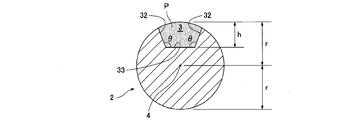
- FIG. 4 is a plan view of the measuring shaft body 2
- FIG. 5 is a sectional view taken along the line AA of FIG. 4
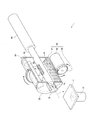
- FIG. 6 is a partially cutaway perspective view of the powder supply device 1.
- 7 and 8 are cross-sectional views of the powder filling mechanism 5
- FIGS. 9 and 10 are partially cutaway perspective views of the powder supply device 1
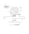
- FIG. 11 is a cross-sectional view of the measuring shaft body 2. It is a figure which shows other configurations.
- the concave portion 3 of the measuring shaft body 2 has, for example, a rectangular shape in a plan view.
- This rectangle is preferably an elongated shape having a ratio of short side to long side of about 1:20 to 1:40, for example.
- the plan view of the recess 3 is elongated, the plan view of the powder P supplied from the recess 3 is also elongated, and the shape suitable for extending the supplied powder P with a squeegee or the like as a post-process. Because it becomes. That is, the powder P can be uniformly supplied along the width direction of the squeegee or the like.
- the plan view of the recess 3 is not limited to a rectangle, and may be another shape such as an oval or an ellipse.
- the recess 3 of the measuring shaft 2 is an opening having a side surface 32 and a bottom surface 33.
- the angle ⁇ formed by the side surface 32 and the bottom surface 33 of the recess 3 is preferably an obtuse angle. This is because if the angle ⁇ is an obtuse angle, the powder P is likely to fall from the downwardly directed recess 3. If the powder P is likely to fall from the downwardly directed recess 3, the powder P is less likely to remain in the downwardly directed recess 3, so that even a small amount of powder P can be supplied in a fixed amount. ..
- the bottom surface 33 of the recess 3 is preferably located at a shallower position (h ⁇ r) than the shaft 4 of the measuring shaft body 2.
- the powder filling mechanism 5 has, for example, a tubular body 50 in which the recess 3 of the measuring shaft body 2 can be located.
- the powder P is arranged inside the tubular body 50.
- the cylinder 50 is cut out in a vertical half in order to display the inside of the cylinder 50.
- the powder filling mechanism 5 has, for example, a cylinder rotating mechanism 54 for rotating the tubular body 50.
- the cylinder rotation mechanism 54 stirs the powder P by rotating the cylinder 50, and fills the recess 3 with the powder P by this stirring.
- the cylinder rotation mechanism 54 has, for example, a drive gear 56 connected to the output shaft of the motor 55, and a driven gear 57 that meshes with the drive gear 56 and is attached to the outer surface of the cylinder 50.
- the powder filling mechanism 5 further includes, for example, a powder stirring blade 58 protruding from the inner surface of the tubular body 50.
- the powder stirring blade 58 promotes stirring of the powder P arranged inside the cylinder 50 as the cylinder 50 rotates. When the stirring of the powder P is promoted, the lump of the powder P is crushed, so that even a small amount of the powder P can be supplied in a fixed amount.
- the powder stirring blades 58 preferably have a plurality of blades (two as an example in FIG. 7), and the plurality of powder stirring blades 58 are arranged at equal pitches, as shown in FIG. Is even more preferable.
- At least one of the plurality of powder stirring blades 58 has a length (that is, a long powder stirring blade 58) whose tip is slightly (d) away from the measuring shaft body 2. ..
- the long powder stirring blade 58 is filled in the recess 3 by its rotation to wipe off the powder P raised from the outer peripheral surface of the measuring shaft 2, so that the powder P in the recess 3 is removed. This is because it stabilizes the filling.
- the distance (d) between the long powder stirring blade 58 and the measuring shaft 2 is preferably equal to or less than the depth (h) of the recess 3.
- the cross section of the tubular body 50 may be circular or polygonal (square in FIG. 8 as an example). As shown in FIG.
- the powder filling mechanism 5 has, for example, an air blowing portion 59 that agitates the powder P by blowing air a inside the tubular body 50.
- the air a is blown into the inside by the air blowing portion 59 is not limited to the cylinder 50 having a square cross section shown in FIG. 8, and any shape of the cylinder 50 may be used.
- the powder supply device 1 is a rotary cylinder that slides the measuring shaft body 2 along the shaft 4 and rotates the measuring shaft body 2 around the shaft 4.
- 68 is provided. That is, the rotary cylinder 68 also serves as the slide mechanism 6 and the shaft rotation mechanism 8 described above.
- the tubular body 50 includes a body 51, a base end side lid plate 52 arranged on one end side of the body 51 and penetrating the base end side of the measuring shaft body 2, and the body.
- a tip side lid plate 72 arranged on the other end side of 51 and allowing the tip end side of the measuring shaft body 2 to penetrate, and a boss member provided on the outer surface of the tip side lid plate 72 and allowing the tip end side of the measuring shaft body 2 to penetrate.
- the shaft body through port 74 formed in the tip side lid plate 72 and the boss member 73 is a space for guiding the recess 3 of the measuring shaft body 2 from the inside to the outside of the cylinder body 50 by sliding.
- the tip side lid plate 72 and the boss member 73 on which the shaft body through port 74 is formed correspond to the above-mentioned sliding member 7.
- the tip side lid plate 72 and the boss member 73 are different members rather than an integral member, it is the tip side lid plate facing the inside of the tubular body 50 that actually scrapes the powder P filled in the recess 3. Since it is 72, the tip side lid plate 72 corresponds to the above-mentioned sliding member 7.
- the cross section of the shaft body through port 74 is the same as the cross section of the measuring shaft body 2 or slightly larger than the cross section of the measuring shaft body 2 (for example, only by a common difference).
- an elevating plate 11 as a predetermined position 10 in which powder P is supplied by dropping from the recess 3 and an elevating cylinder 12 for raising and lowering the elevating plate 11 may be provided.
- the elevating cylinder 12 can raise the elevating plate 11 to a preferable height of the elevating plate 11 when the powder P is supplied from the recess 3.
- the preferable height of the elevating plate 11 is that the distance (h + ⁇ ) between the lower end of the measuring shaft 2 and the surface to which the powder P is supplied from the recess 3 makes the depth (h) of the recess 3 slightly ( ⁇ ). ) Is exceeded.
- the height (h + ⁇ ) of the powder P falling from the recess 3 can be minimized, so that the powder P does not lose its shape due to the drop, and the supplied powder P is used as a post-process. This is because the shape is suitable for stretching with a squeegee or the like.
- a shaft vibration mechanism 9 for vibrating the measuring shaft body 2 may be provided.
- the shaft vibration mechanism 9 promotes the fall of the powder P from the recess 3 by vibrating the measuring shaft body 2 in a state where the recess 3 is directed downward.
- the cylinder body 50 is rotated by the cylinder rotation mechanism 54.
- the powder P arranged inside the cylinder 50 is agitated by this rotation.
- the agitated powder P soars higher than the recess 3 of the measuring shaft body 2 to fill the recess 3.
- the measuring shaft 2 is slid by the rotary cylinder 68 as shown in FIG.
- the time point at which the powder P is filled to the extent that it rises from the recess 3 can be estimated from the rotation speed or rotation time of the tubular body 50.
- the measuring shaft 2 may be automatically slid by the rotary cylinder 68.
- the recess 3 comes out from the inside of the cylinder body 50 to the outside of the cylinder body 50 through the shaft body through port 74.
- the recess 3 passes through the shaft through port 74, the powder P filled to the extent that the recess 3 rises is worn out. Therefore, the recess 3 protruding to the outside of the tubular body 50 is in a state where the filled powder P is worn out.
- the elevating plate 11 is raised by the elevating cylinder 12. Specifically, as shown in FIG. 11, the elevating plate 11 is raised to the above-mentioned preferable height. Then, the measuring shaft body 2 is rotated around the shaft 4 by the rotary cylinder 68, so that the recess 3 is directed downward. When the recess 3 comes out of the cylinder 50 and the elevating plate 11 is positioned at a preferable height, the rotary cylinder 68 automatically rotates the measuring shaft 2 around the shaft 4. May be good.
- the powder P is supplied to the elevating plate 11 by dropping the powder P from the downwardly directed recess 3 onto the elevating plate 11 below. In order to promote this fall, the shaft vibration mechanism 9 vibrates the measuring shaft body 2 in a state where the recess 3 is directed downward.
- the powder P that has been scraped off by the scraping member 7 is supplied, so that even a small amount of powder P can be supplied in a fixed amount. Further, since the powder P is supplied from the recess 3 after being slid from the position where the powder P is filled, a space can be secured above the predetermined position 10 where the powder P is supplied.
- the powder P is agitated inside the tubular body 50 and the lump of the powder P is crushed. Even a small amount of powder P can be supplied in a fixed amount. Further, by rotating the tubular body 50 in which the powder P is arranged by the tubular rotating mechanism 54, it is possible to estimate the time when the concave portion 3 is filled, which is suitable for automation.
- the powder stirring blade 58 and the air spraying portion 59 promote the stirring of the powder P inside the tubular body 50, the mass of the powder P is further crushed, so that a small amount of the powder P is crushed. Even if it can be supplied in a fixed quantity.
- the sliding member 7 is a member (tip side lid plate 72) constituting the tubular body 50, the configuration can be simplified.
- the powder P is likely to fall from the downwardly directed recess 3, so that even a small amount of the powder P can be supplied in a fixed amount. it can.
- the powder P has not been described in detail, but the powder P is not particularly limited and may be any powder P.
- a preferable powder P is one that is supplied by the powder supply device 1, spread by a squeegee or the like in a subsequent step, and then pressurized at a high pressure to form a solid material.
- measuring shaft body 2 having a circular cross section is shown, but other shapes such as a polygon may be used.
- the configuration required for confirmation by the device is the detector 30 and the control mechanism 65.
- the detector 30 detects the filling state of the powder P that has been scraped off by the scraping member 7 in the recess 3.
- the specific detector 30 is a device such as a laser side lengthening device or a camera (image detection) that measures the shape of the recess 3 or recognizes the filling state of the powder P in the recess 3.
- the control mechanism 65 slides the measuring shaft 2 to the position where the powder P is filled (refilled) in the recess 3 by the slide mechanism 6. , The powder P is filled (refilled) in the recess 3 by the powder filling mechanism 5.
- "insufficient” means that the recess 3 is not filled with the amount of powder P required for supplying the powder in a quantitative manner.
- a control having a determination unit for determining whether the filling state detected by the detector 30 is insufficient and an instruction unit for instructing the powder filling mechanism 5 and the slide mechanism 6 Such as a board.
- the powder supply device 1 may include both the detector 30 shown in FIG. 12 and the detector 30 shown in FIG.
Landscapes
- Engineering & Computer Science (AREA)
- Chemical & Material Sciences (AREA)
- Materials Engineering (AREA)
- Manufacturing & Machinery (AREA)
- Physics & Mathematics (AREA)
- Mechanical Engineering (AREA)
- Fluid Mechanics (AREA)
- General Physics & Mathematics (AREA)
- Optics & Photonics (AREA)
- Filling Or Emptying Of Bunkers, Hoppers, And Tanks (AREA)
- Basic Packing Technique (AREA)
Abstract
粉体(P)が充填される凹部(3)を有する計量軸体(2)と、この計量軸体(2)の凹部(3)に粉体(P)を充填する粉体充填機構(5)とを備える粉体供給装置(1)である。粉体供給装置(1)は、計量軸体(2)を当該計量軸体(2)の軸(4)に沿ってスライドさせる回転式シリンダ(68)と、凹部(3)に充填された粉体(P)を計量軸体(2)のスライドにより摺り切る筒体(50)の先端側蓋板(72)とを備える。回転式シリンダ(68)は、計量軸体(2)を当該計量軸体(2)の軸(4)回りに回転させることで凹部(3)を下方に向け、凹部(3)の摺り切られた粉体(P)を当該凹部(3)から落下により下方の所定位置(10)である昇降板(11)に供給する。
Description
本発明は、粉体供給装置に関するものである。
近年、粉体を均一に敷き詰め、高圧で加圧して得られる固形材料が工業的に利用されている。このような固形材料は、通常、形状などで高い精度が要求される。このため、前記固形材料を形成するための粉体の量は、一定である必要がある。したがって、前記固形材料を形成する装置に対して、粉体を可能な限り一定にして供給する装置(粉体供給装置)が使用されている。
従来の粉体供給装置として、日本国特開2016-147253号公報(以下、特許文献1)に、棒状体の計量凹部から粉体を確実に落下させて供給する装置が提案されている。前記特許文献1に記載の粉体供給装置は、計量凹部からエアを放出するように構成することで、計量凹部からの粉体の落下を確実にしている。
ところで、前記特許文献1に記載の粉体供給装置には、棒状体の計量凹部に充填された粉体が、当該棒状体がその位置のまま軸回りに180°回転することで、計量凹部から落下して供給される。このため、前記特許文献1に記載の粉体供給装置に流動性の悪い粉体が用いられる場合、定量の粉体が計量凹部に充填されないまま、当該計量凹部から供給されるおそれがある。また、粒径の小さい粉体が用いられる場合、棒状体と摺接部の間に当該粉体が巻き込まれるなどして、棒状体の計量凹部以外の部分に粉体が付着し、計量凹部に充填された粉体とともに棒状体に付着した粉体が供給されるおそれがある。特に、1.0gf[9.8×10⁻³N]未満となる微量の粉体を供給する場合、供給する粉体の重量が僅かに増減しても、この増減は供給を予定していた粉体に対する割合が大きくなるので、粉体を定量で供給することが困難である。
また、前記特許文献1に記載の粉体供給装置は、粉体を供給する所定位置の上方において、当該特許文献1の図1に示すように、粉体撹拌機構50、および、計量凹部34に粉体を充填するホッパ部21など、様々な構成が必要である。粉体が供給される所定位置の上方は、粉体供給装置の後工程(粉体を敷き詰める工程など)で必要となる空間であるから、このような空間が確保されていなければ、後工程で使用される装置が制限されることになる。
そこで、本発明は、微量の粉体であっても定量で供給し得るとともに、粉体が供給される所定位置の上方に空間を確保し得る粉体供給装置を提供することを目的とする。
前記課題を解決するため、第1の発明に係る粉体供給装置は、粉体が充填される凹部を有する計量軸体と、
前記計量軸体の凹部に粉体を充填する粉体充填機構と、
前記計量軸体を当該計量軸体の軸に沿ってスライドさせるスライド機構と、
前記凹部に充填された粉体を計量軸体のスライドにより摺り切る摺切部材と、
前記計量軸体を当該計量軸体の軸回りに回転させることで凹部を下方に向け、当該凹部の摺り切られた粉体を当該凹部から落下により下方に供給する軸回転機構とを備えるものである。
前記計量軸体の凹部に粉体を充填する粉体充填機構と、
前記計量軸体を当該計量軸体の軸に沿ってスライドさせるスライド機構と、
前記凹部に充填された粉体を計量軸体のスライドにより摺り切る摺切部材と、
前記計量軸体を当該計量軸体の軸回りに回転させることで凹部を下方に向け、当該凹部の摺り切られた粉体を当該凹部から落下により下方に供給する軸回転機構とを備えるものである。
また、第2の発明に係る粉体供給装置は、第1の発明に係る粉体供給装置における粉体充填機構が、
内部に計量軸体の少なくとも凹部が位置し得るとともに、当該内部に粉体が配置される筒体と、
前記筒体を回転させることで、前記内部の粉体を撹拌し凹部に充填する筒回転機構とを有するものである。
内部に計量軸体の少なくとも凹部が位置し得るとともに、当該内部に粉体が配置される筒体と、
前記筒体を回転させることで、前記内部の粉体を撹拌し凹部に充填する筒回転機構とを有するものである。
さらに、第3の発明に係る粉体供給装置は、第2の発明に係る粉体供給装置における粉体充填機構が、筒体の内面から突出した粉体撹拌羽根をさらに有するものである。
加えて、第4の発明に係る粉体供給装置は、第2または第3の発明に係る粉体供給装置における粉体充填機構が、筒体の内部にエアを吹き付けることで粉体を撹拌するエア吹付部をさらに有するものである。
また、第5の発明に係る粉体供給装置は、第2または第3の発明に係る粉体供給装置における摺切部材が、スライドにより計量軸体の凹部を筒体の内部から外部に案内する軸体貫通口が形成された部材である。
また、第6の発明に係る粉体供給装置は、第1乃至第3のいずれかの発明に係る粉体供給装置において、下方に向けられた凹部からの粉体の落下を振動により促進する軸振動機構をさらに備えるものである。
また、第7の発明に係る粉体供給装置は、第1乃至第3のいずれかの発明に係る粉体供給装置において、摺切部材で摺り切られた粉体の凹部における充填状態を検知する検知器と、
検知器で検知された粉体の充填状態が不十分であれば、スライド機構により計量軸体をその凹部に粉体が充填される位置までスライドさせ、粉体充填機構により当該凹部に粉体を充填させる制御機構とをさらに備えるものである。
検知器で検知された粉体の充填状態が不十分であれば、スライド機構により計量軸体をその凹部に粉体が充填される位置までスライドさせ、粉体充填機構により当該凹部に粉体を充填させる制御機構とをさらに備えるものである。
前記粉体供給装置によると、摺切部材で摺り切られた粉体が供給されるので、微量の粉体であっても定量で供給することができる。また、粉体は凹部に充填される位置からスライドされた後に当該凹部から供給されるので、粉体が供給される所定位置の上方に空間を確保することができる。
以下、本発明の実施の形態に係る粉体供給装置について、図面に基づき説明する。
まず、この粉体供給装置の概略について、図1~図3に基づき説明する。図1~図3は、前記粉体供給装置の概略側面図である。
図1に示すように、この粉体供給装置1は、粉体Pが充填される凹部3を有する計量軸体2と、この計量軸体2の凹部3に粉体Pを充填する粉体充填機構5とを備える。また、図2に示すように、前記粉体供給装置1は、前記計量軸体2をその軸4に沿ってスライドさせるスライド機構6と、前記凹部3に充填された粉体Pを計量軸体2のスライドにより摺り切る摺切部材7とを備える。さらに、図3に示すように、前記粉体供給装置1は、前記計量軸体2をその軸4回りに回転させることで凹部3を下方に向け、当該凹部3の摺り切られた粉体Pを当該凹部3から落下により下方の所定位置10に供給する軸回転機構8を備える。
前記粉体供給装置1の使用方法としては、まず、図1に示すように、粉体充填機構5により、計量軸体2の凹部3に粉体Pを充填する。当該凹部3に充填された粉体Pは、凹部3から盛り上がっていてもよい。次に、図2に示すように、スライド機構6により計量軸体2をスライドさせることで、前記凹部3に充填された粉体Pを摺切部材7で摺り切らせる。この摺り切りにより、凹部3から盛り上がった部分の粉体Pは、凹部3から落下する。その後、図3に示すように、軸回転機構8により、前記計量軸体2をその軸4回りに回転させることで凹部3を下方に向ける。下方に向けられた凹部3からは、粉体Pが下方に落下することで、当該粉体Pが下方の所定位置10に供給される。
次に、前記粉体供給装置1の前述した各構成について、図4~図11に基づき詳細に説明する。図4は前記計量軸体2の平面図、図5は図4のA-A断面図、図6は前記粉体供給装置1の一部切欠き斜視図である。また、図7および図8は前記粉体充填機構5の横断面図、図9および図10は前記粉体供給装置1の一部切欠き斜視図、図11は計量軸体2の横断面およびその他の構成を示す図である。
[計量軸体2]
[計量軸体2]
図4に示すように、前記計量軸体2の凹部3は、例えば、平面視が長方形である。この長方形は、例えば、短辺および長辺の比が1:20~1:40程度の細長い形状であることが好ましい。凹部3の平面視が細長い形状であることにより、凹部3から供給される粉体Pの平面視も細長い形状になり、供給された粉体Pを後工程としてスキージなどで延ばすのに適した形状になるからである。すなわち、スキージなどの幅方向に沿って均一に粉体Pを供給できるからである。なお、前記凹部3の平面視は、長方形に限られず、長円または楕円など他の形状でもよい。
図5に示すように、前記計量軸体2の凹部3は、側面32および底面33を有する開口である。前記凹部3の側面32と底面33とのなす角θは、鈍角であることが好ましい。当該角θが鈍角であれば、下方に向けられた凹部3から粉体Pが落下しやすくなるからである。下方に向けられた凹部3から粉体Pが落下しやすくなれば、下方に向けられた凹部3に粉体Pが残りにくくなるので、微量の粉体Pであっても定量で供給可能になる。前記凹部3の底面33は、計量軸体2の軸4よりも浅い位置(h<r)にすることが好ましい。底面33が浅ければ、軸回転機構8による計量軸体2の回転で、凹部3に充填された粉体Pに遠心力が与えられることにより、下方に向けられた凹部3から粉体Pが落下しやすくなるからである。
[粉体充填機構5]
[粉体充填機構5]
図6に示すように、前記粉体充填機構5は、例えば、内部に計量軸体2の凹部3が位置し得る筒体50を有する。この筒体50は、内部に粉体Pが配置されるものである。図6では(後述する図9および図10でも)、前記筒体50の内部まで表示するために、当該筒体50を縦半分に切り欠いて示す。また、前記粉体充填機構5は、例えば、前記筒体50を回転させる筒回転機構54を有する。この筒回転機構54は、前記筒体50の回転により粉体Pを撹拌させ、この撹拌により当該粉体Pを凹部3に充填するものである。前記筒回転機構54は、例えば、モータ55の出力軸に連結された駆動ギヤ56と、この駆動ギヤ56に噛み合うとともに前記筒体50の外面に取り付けられた従動ギヤ57とを有する。
図6および図7に示すように、前記粉体充填機構5は、例えば、筒体50の内面から突出した粉体撹拌羽根58をさらに有する。当該粉体撹拌羽根58は、筒体50の回転に伴って、筒体50の内部に配置された粉体Pの撹拌を促進するものである。粉体Pの撹拌が促進されると、粉体Pの塊が解砕されるので、微量の粉体Pであっても定量で供給可能になる。前記粉体撹拌羽根58は、撹拌を一層促進するために、図7に示すように、複数枚(図7では一例として2枚)であることが好ましく、複数枚が等ピッチで配置されていることが一層好ましい。ここで、複数枚の粉体撹拌羽根58のうち少なくとも1枚は、その先端が計量軸体2から少し(d)だけ離れた長さ(つまり、長い粉体撹拌羽根58)であることが好ましい。これにより、この長い粉体撹拌羽根58が、その回転により、前記凹部3に充填されて計量軸体2の外周面から盛り上がった粉体Pを払い落すので、当該凹部3への粉体Pの充填を安定させるからである。なお、前記長い粉体撹拌羽根58と計量軸体2との距離(d)は、前記凹部3の深さ(h)以下であることが好ましい。前記筒体50の横断面は、円形であってもよく、多角形(図8では一例として正方形)であってもよい。図8に示すように、前記筒体50の横断面が正方形など多角形であれば、筒体50の回転に伴って、当該筒体50の隅にある粉体Pが上方まで運ばれやすくなるので、粉体Pの撹拌が促進される。前記粉体充填機構5は、例えば、筒体50の内部にエアaを吹き付けることで粉体Pを撹拌するエア吹付部59を有する。エア吹付部59により内部にエアaが吹き付けられるのは、図8に示す横断面が正方形の筒体50に限られず、どのような形状の筒体50でもよい。
[スライド機構6および軸回転機構8]
[スライド機構6および軸回転機構8]
図9および図10に示すように、前記粉体供給装置1は、計量軸体2をその軸4に沿ってスライドさせるとともに、当該計量軸体2をその軸4回りに回転させる、回転式シリンダ68を備える。すなわち、この回転式シリンダ68は、前述したスライド機構6および軸回転機構8を兼ねるものである。
[摺切部材7]
[摺切部材7]
図9および図10に示すように、前記筒体50は、胴体51と、この胴体51の一端側に配置されて計量軸体2の基端側が貫通した基端側蓋板52と、前記胴体51の他端側に配置されて計量軸体2の先端側が貫通自在の先端側蓋板72と、この先端側蓋板72の外面に設けられて計量軸体2の先端側が貫通自在のボス部材73とを有する。先端側蓋板72およびボス部材73に形成された軸体貫通口74は、スライドにより計量軸体2の凹部3を筒体50の内部から外部に案内する空間である。すなわち、この軸体貫通口74が形成された先端側蓋板72およびボス部材73が、前述した摺切部材7に相当する。なお、先端側蓋板72およびボス部材73が一体の部材ではなく異なる部材の場合、凹部3に充填された粉体Pを実際に摺り切るのは筒体50の内部に面した先端側蓋板72なので、この先端側蓋板72が前述した摺切部材7に相当する。前記軸体貫通口74の横断面は、前記計量軸体2の横断面と同一、または、前記計量軸体2の横断面よりも僅かに(例えば公差分だけ)大きいことが好ましい。このような軸体貫通口74により、摺り切られて凹部3に残る粉体Pの量のばらつきが小さくなる。摺り切られて凹部3に残る粉体Pの量のばらつきが小さくなると、微量の粉体Pであっても定量で供給可能になる。
[その他の構成]
[その他の構成]
図10および図11に示すように、凹部3から粉体Pが落下により供給される所定位置10としての昇降板11と、この昇降板11を昇降させる昇降シリンダ12とが設けられてもよい。図11に示すように、前記昇降シリンダ12は、凹部3から粉体Pが供給される際における昇降板11の好ましい高さまで、当該昇降板11を上昇させ得る。ここで、昇降板11の好ましい高さとは、計量軸体2の下端と粉体Pが凹部3から供給される面との距離(h+α)が、凹部3の深さ(h)を僅か(α)に超える程度である。この高さであれば、凹部3から落下する粉体Pの高さ(h+α)を最小限に抑えられるので、粉体Pが落下により形状を崩さず、供給された粉体Pを後工程としてスキージなどで延ばすのに適した形状になるからである。
図11に示すように、計量軸体2を振動させる軸振動機構9が設けられてもよい。この軸振動機構9は、凹部3が下方に向けられた状態の計量軸体2を振動させることにより、凹部3から粉体Pの落下を促進させるものである。
次に、前記粉体供給装置1の使用方法について詳細に説明する。
まず、図6および図7に示すように、筒回転機構54により、筒体50を回転させる。筒体50の内部に配置された粉体Pは、この回転により撹拌される。撹拌された粉体Pは、計量軸体2の凹部3よりも高く舞い上がることで、当該凹部3に充填されていく。
次に、粉体Pが凹部3から盛り上がる程度まで充填された時点で、図9に示すように、回転式シリンダ68により計量軸体2をスライドさせる。粉体Pが凹部3から盛り上がる程度まで充填された時点は、筒体50の回転数または回転時間により推測することが可能である。この回転数または回転時間に達した時点で、自動的に回転式シリンダ68により計量軸体2をスライドさせるように構成してもよい。計量軸体2のスライドにより、凹部3が筒体50の内部から軸体貫通口74を経て筒体50の外部に出る。凹部3が軸体貫通口74を通過する際に、当該凹部3から盛り上がる程度まで充填された粉体Pが摺り切られる。このため、筒体50の外部に出た凹部3は、充填された粉体Pが摺り切られた状態である。
その後、図10および図11に示すように、昇降シリンダ12により昇降板11を上昇させる。具体的には、図11に示すように、前述した好ましい高さまで昇降板11を上昇させる。そして、回転式シリンダ68により計量軸体2をその軸4回りに回転させることで凹部3を下方に向ける。凹部3が筒体50の外部に出て、昇降板11が好ましい高さに位置した時点で、自動的に回転式シリンダ68により計量軸体2をその軸4回りに回転させるように構成してもよい。下方に向けられた凹部3からは、粉体Pが下方の昇降板11に落下することで、当該粉体Pが昇降板11に供給される。この落下を促進させるために、軸振動機構9により、凹部3が下方に向けられた状態の計量軸体2を振動させる。
このように、前記粉体供給装置1によると、摺切部材7で摺り切られた粉体Pが供給されるので、微量の粉体Pであっても定量で供給することができる。また、粉体Pは凹部3に充填される位置からスライドされた後に当該凹部3から供給されるので、粉体Pが供給される所定位置10の上方に空間を確保することができる。
また、粉体Pが内部に配置された筒体50を筒回転機構54により回転させることで、筒体50の内部で粉体Pが撹拌され、粉体Pの塊が解砕されるので、微量の粉体Pであっても定量で供給することができる。さらに、粉体Pが内部に配置された筒体50を筒回転機構54により回転させることで、凹部3に充填される時点を推測可能であるから、自動化に適することができる。
加えて、筒体50の内部で粉体撹拌羽根58およびエア吹付部59により粉体Pの撹拌が促進されるので、粉体Pの塊が一層解砕されることにより、微量の粉体Pであっても定量で供給することができる。
また、摺切部材7が筒体50を構成する部材(先端側蓋板72)であることにより、構成を簡素にすることができる。
また、軸振動機構9で計量軸体2を振動させることにより、下方に向けられた凹部3から粉体Pが落下しやすくなるので、粉体Pが微量であっても定量で供給することができる。
ところで、前記実施の形態では、粉体Pについて詳細に説明しなかったが、特に制限されるものではなく、粉体Pであればよい。好ましい粉体Pは、前記粉体供給装置1で供給されてから、後工程によりスキージなどで延ばして敷き詰められてから、高圧で加圧されて固形材料とされるものである。
また、前記実施の形態では、計量軸体2の横断面が円形のもののみを図示したが、多角形など他の形状でもよい。
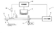
さらに、前記実施の形態では、粉体Pの摺り切られた後で且つ下方に供給される前の充填状態を確認することについて説明しなかったが、当該確認を行うことが好ましい。この確認は、目視でもよいが、機器により行われることが確実性および自動化のために好ましい。機器による確認に必要な構成は、図12および図13に示すように、検知器30および制御機構65である。前記検知器30は、摺切部材7で摺り切られた粉体Pの凹部3における充填状態を検知するものである。具体的な前記検知器30としては、レーザ側長器またはカメラ(画像検知)など当該凹部3の形状を測定または粉体Pの当該凹部3への充填状態を認識する機器である。前記制御機構65は、検知器30で検知された充填状態が不十分であれば、スライド機構6により計量軸体2をその凹部3に粉体Pが充填(再充填)される位置までスライドさせ、粉体充填機構5により当該凹部3に粉体Pを充填(再充填)させるものである。ここで、不十分とは、定量で供給するために必要な量の粉体Pが凹部3に充填されていないことを意味する。具体的な前記制御機構65としては、検知器30で検知された充填状態が不十分であるかを判断する判断部と、粉体充填機構5およびスライド機構6に指示する指示部とを有する制御盤などである。図12に示す検知器30は、摺切部材7で摺り切られている粉体Pの充填状態を検知する方向に配置される。これにより、摺り切られた粉体Pの充填状態が不十分であれば、直ちに制御機構65により凹部3に粉体Pが再充填されるので、定量の粉体Pが供給されるのに要する時間を短縮することができる。一方で、図13に示す検知器30は、下方に供給される直前の粉体Pの充填状態を検知する方向に配置される。これにより、確実に粉体Pを定量で供給することができる。なお、前記粉体供給装置1は、図12に示す検知器30と、図13に示す検知器30との両方を備えてもよい。
加えて、前記実施の形態は、全ての点で例示であって制限的なものではない。本発明の範囲は、前述した説明ではなく請求の範囲によって示され、請求の範囲と均等の意味および範囲内での全ての変更が含まれることが意図される。前記実施の形態で説明した構成のうち「課題を解決するための手段」での第1の発明として記載した構成以外については、任意の構成であり、適宜削除および変更することが可能である。
Claims (7)
- 粉体が充填される凹部を有する計量軸体と、
前記計量軸体の凹部に粉体を充填する粉体充填機構と、
前記計量軸体を当該計量軸体の軸に沿ってスライドさせるスライド機構と、
前記凹部に充填された粉体を計量軸体のスライドにより摺り切る摺切部材と、
前記計量軸体を当該計量軸体の軸回りに回転させることで凹部を下方に向け、当該凹部の摺り切られた粉体を当該凹部から落下により下方に供給する軸回転機構とを備えることを特徴とする粉体供給装置。 - 粉体充填機構が、
内部に計量軸体の少なくとも凹部が位置し得るとともに、当該内部に粉体が配置される筒体と、
前記筒体を回転させることで、前記内部の粉体を撹拌し凹部に充填する筒回転機構とを有することを特徴とする請求項1に記載の粉体供給装置。 - 粉体充填機構が、筒体の内面から突出した粉体撹拌羽根をさらに有することを特徴とする請求項2に記載の粉体供給装置。
- 粉体充填機構が、筒体の内部にエアを吹き付けることで粉体を撹拌するエア吹付部をさらに有することを特徴とする請求項2または3に記載の粉体供給装置。
- 摺切部材が、スライドにより計量軸体の凹部を筒体の内部から外部に案内する軸体貫通口が形成された部材であることを特徴とする請求項2または3に記載の粉体供給装置。
- 下方に向けられた凹部からの粉体の落下を振動により促進する軸振動機構をさらに備えることを特徴とする請求項1乃至3のいずれか一項に記載の粉体供給装置。
- 摺切部材で摺り切られた粉体の凹部における充填状態を検知する検知器と、
検知器で検知された粉体の充填状態が不十分であれば、スライド機構により計量軸体をその凹部に粉体が充填される位置までスライドさせ、粉体充填機構により当該凹部に粉体を充填させる制御機構とをさらに備えることを特徴とする請求項1乃至3のいずれか一項に記載の粉体供給装置。
Priority Applications (4)
| Application Number | Priority Date | Filing Date | Title |
|---|---|---|---|
| US17/630,183 US12055424B2 (en) | 2019-09-20 | 2020-09-15 | Powder supply apparatus |
| KR1020227003897A KR20220061949A (ko) | 2019-09-20 | 2020-09-15 | 분체공급장치 |
| EP20864614.1A EP4032837A4 (en) | 2019-09-20 | 2020-09-15 | POWDER DISTRIBUTION APPARATUS |
| JP2021520439A JP7324279B2 (ja) | 2019-09-20 | 2020-09-15 | 粉体供給装置 |
Applications Claiming Priority (2)
| Application Number | Priority Date | Filing Date | Title |
|---|---|---|---|
| JP2019170951 | 2019-09-20 | ||
| JP2019-170951 | 2019-09-20 |
Publications (1)
| Publication Number | Publication Date |
|---|---|
| WO2021054310A1 true WO2021054310A1 (ja) | 2021-03-25 |
Family
ID=74883213
Family Applications (1)
| Application Number | Title | Priority Date | Filing Date |
|---|---|---|---|
| PCT/JP2020/034838 Ceased WO2021054310A1 (ja) | 2019-09-20 | 2020-09-15 | 粉体供給装置 |
Country Status (5)
| Country | Link |
|---|---|
| US (1) | US12055424B2 (ja) |
| EP (1) | EP4032837A4 (ja) |
| JP (1) | JP7324279B2 (ja) |
| KR (1) | KR20220061949A (ja) |
| WO (1) | WO2021054310A1 (ja) |
Citations (8)
| Publication number | Priority date | Publication date | Assignee | Title |
|---|---|---|---|---|
| JPS53150714U (ja) * | 1977-05-02 | 1978-11-28 | ||
| JPS59206717A (ja) * | 1983-05-10 | 1984-11-22 | Hiroshi Adachi | 粉末計量器 |
| JPS60102623U (ja) * | 1983-12-20 | 1985-07-12 | 東洋自動機株式会社 | 計量装置 |
| JP2599220Y2 (ja) * | 1993-10-18 | 1999-08-30 | エフエム技研株式会社 | 粉粒体の混合装置 |
| JP2000266643A (ja) * | 1999-03-15 | 2000-09-29 | Tokyo Rika Kikai Kk | 粉粒体試料定量分配器 |
| JP2014061913A (ja) * | 2012-09-21 | 2014-04-10 | Yokoyama Corp | 粉粒体用計量容器 |
| JP2016147253A (ja) | 2015-02-13 | 2016-08-18 | 関西ペイント株式会社 | 粉体供給装置 |
| JP2016204131A (ja) * | 2015-04-24 | 2016-12-08 | トヨタ自動車株式会社 | 粉体供給装置 |
Family Cites Families (20)
| Publication number | Priority date | Publication date | Assignee | Title |
|---|---|---|---|---|
| US2856807A (en) * | 1954-04-13 | 1958-10-21 | Noble D Stutzman | Powder measuring dispenser |
| US3201001A (en) * | 1962-10-12 | 1965-08-17 | Borden Co | Pulverulent materials dispenser |
| GB1118520A (en) | 1967-06-20 | 1968-07-03 | Maharaj Krishen Mehta | Dispensing apparatus for use in encapsulating powders |
| JPS5252960A (en) * | 1975-10-27 | 1977-04-28 | Tadashi Iijima | Device for quantitatively supplying coloring material |
| DE2914238C2 (de) * | 1979-03-02 | 1981-04-23 | Schweizerische Aluminium AG, 3965 Chippis | Vorrichtung zur kontinuierlichen Tonerdezuführung mittels einer Dosiervorrichtung |
| DE3217406C2 (de) * | 1982-05-08 | 1986-06-05 | Pfister Gmbh, 8900 Augsburg | Vorrichtung zum kontinuierlichen gravimetrischen Dosieren von schüttfähigem Gut |
| DE3476778D1 (en) * | 1984-03-29 | 1989-03-23 | Engstrom Nils G | Apparatus for dynamometer testing of motor vehicles |
| US4635829A (en) | 1985-05-30 | 1987-01-13 | Brittingham Jr Louis W | Measured volume dispenser |
| FR2587081B1 (fr) * | 1985-09-11 | 1988-04-15 | Bp Chimie Sa | Dispositif doseur de type rotatif permettant de delivrer des substances granulaires |
| US4751948A (en) * | 1985-10-30 | 1988-06-21 | Kendall Mcgaw Laboratories, Inc. | Method and apparatus for the accurate delivery of powders |
| US4890535A (en) * | 1989-01-24 | 1990-01-02 | Bieber William J | Apparatus and method for measuring and dispensing powder |
| FR2647208B1 (fr) * | 1989-05-16 | 1993-09-24 | Cloup Philippe | Dispositif doseur d'un liquide contenu dans une premiere chambre et a transferer par petites doses dans un fluide s'ecoulant dans une deuxieme chambre |
| JP3220431B2 (ja) | 1998-06-23 | 2001-10-22 | ピップフジモト株式会社 | 計量用具 |
| US6470163B1 (en) | 1999-10-27 | 2002-10-22 | Canon Kabushiki Kaisha | Developer stirring member, assembly method and recycling method for the same |
| KR100864713B1 (ko) | 2006-07-20 | 2008-10-23 | 삼성전자주식회사 | 토너교반필름, 토너교반부재 및 이를 구비한 토너공급장치 |
| GB0813242D0 (en) | 2008-07-18 | 2008-08-27 | Mcp Tooling Technologies Ltd | Powder dispensing apparatus and method |
| GB201020646D0 (en) | 2010-12-06 | 2011-01-19 | Molins Plc | Apparatus for dispensing powder |
| WO2015008348A1 (ja) | 2013-07-17 | 2015-01-22 | 日本たばこ産業株式会社 | 粉粒体の定量供給装置及びその定量供給方法 |
| KR101523437B1 (ko) | 2013-10-28 | 2015-05-27 | 김진복 | 분말 공급장치 |
| US9296502B1 (en) * | 2014-08-05 | 2016-03-29 | Aaron Hollander | Ground coffee dispenser for making coffee pods |
-
2020
- 2020-09-15 WO PCT/JP2020/034838 patent/WO2021054310A1/ja not_active Ceased
- 2020-09-15 US US17/630,183 patent/US12055424B2/en active Active
- 2020-09-15 EP EP20864614.1A patent/EP4032837A4/en active Pending
- 2020-09-15 KR KR1020227003897A patent/KR20220061949A/ko not_active Withdrawn
- 2020-09-15 JP JP2021520439A patent/JP7324279B2/ja active Active
Patent Citations (8)
| Publication number | Priority date | Publication date | Assignee | Title |
|---|---|---|---|---|
| JPS53150714U (ja) * | 1977-05-02 | 1978-11-28 | ||
| JPS59206717A (ja) * | 1983-05-10 | 1984-11-22 | Hiroshi Adachi | 粉末計量器 |
| JPS60102623U (ja) * | 1983-12-20 | 1985-07-12 | 東洋自動機株式会社 | 計量装置 |
| JP2599220Y2 (ja) * | 1993-10-18 | 1999-08-30 | エフエム技研株式会社 | 粉粒体の混合装置 |
| JP2000266643A (ja) * | 1999-03-15 | 2000-09-29 | Tokyo Rika Kikai Kk | 粉粒体試料定量分配器 |
| JP2014061913A (ja) * | 2012-09-21 | 2014-04-10 | Yokoyama Corp | 粉粒体用計量容器 |
| JP2016147253A (ja) | 2015-02-13 | 2016-08-18 | 関西ペイント株式会社 | 粉体供給装置 |
| JP2016204131A (ja) * | 2015-04-24 | 2016-12-08 | トヨタ自動車株式会社 | 粉体供給装置 |
Non-Patent Citations (1)
| Title |
|---|
| See also references of EP4032837A4 |
Also Published As
| Publication number | Publication date |
|---|---|
| KR20220061949A (ko) | 2022-05-13 |
| US20220268616A1 (en) | 2022-08-25 |
| JPWO2021054310A1 (ja) | 2021-03-25 |
| EP4032837A4 (en) | 2023-11-01 |
| JP7324279B2 (ja) | 2023-08-09 |
| US12055424B2 (en) | 2024-08-06 |
| EP4032837A1 (en) | 2022-07-27 |
Similar Documents
| Publication | Publication Date | Title |
|---|---|---|
| CN110195505A (zh) | 抹平机器人 | |
| CN108995215A (zh) | 应用于3d打印机的铺粉装置 | |
| WO2021054310A1 (ja) | 粉体供給装置 | |
| US20190055079A1 (en) | Powder feeding apparatus and method thereof | |
| JP2009184778A (ja) | 粉体の微量フィーダ装置 | |
| CN107200230A (zh) | 一种转盘式连续微量粉体输送装置 | |
| KR102486714B1 (ko) | 3d 콘크리트 프린터의 인공지능 기반 토출제어 시스템 | |
| JP6888293B2 (ja) | 充填ノズル | |
| JP5430170B2 (ja) | 粉体の定量フィーダ装置 | |
| JP5220396B2 (ja) | 頭付棒状部品供給装置、及び時計の製造方法 | |
| US6977721B2 (en) | Foreign substance inspection apparatus | |
| CN111350117B (zh) | 物料摊铺执行装置及物料摊铺机器人 | |
| KR101648579B1 (ko) | 죽염 충진장치 | |
| JP4858961B2 (ja) | 粉体充填装置 | |
| JP3604132B2 (ja) | 分注装置 | |
| CN109459915B (zh) | 一种打印机墨粉耗材制作加工设备及墨粉耗材制作工艺 | |
| JP3124230U (ja) | 粉体充填装置 | |
| JPWO2018100804A1 (ja) | 鋳物砂用のバインダ供給装置及びバインダ供給方法 | |
| JP5680281B2 (ja) | 粉体の定量フィーダ装置 | |
| CN220719821U (zh) | 一种水泥石灰剂量试验搅拌装置 | |
| JP7741876B2 (ja) | 成型装置及び成型方法 | |
| JP2007044152A (ja) | 粉末原料供給装置 | |
| CN108928604B (zh) | 一种振动给料装置 | |
| JP3129639U (ja) | ガトー・ピレネーの自動製造装置 | |
| CN211112319U (zh) | 一种压料装置 |
Legal Events
| Date | Code | Title | Description |
|---|---|---|---|
| ENP | Entry into the national phase |
Ref document number: 2021520439 Country of ref document: JP Kind code of ref document: A |
|
| 121 | Ep: the epo has been informed by wipo that ep was designated in this application |
Ref document number: 20864614 Country of ref document: EP Kind code of ref document: A1 |
|
| NENP | Non-entry into the national phase |
Ref country code: DE |
|
| ENP | Entry into the national phase |
Ref document number: 2020864614 Country of ref document: EP Effective date: 20220420 |